1
www.conairnet.com
USER GUIDE
UGD028-0107
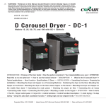
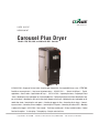
Carousel Plus Dryer
Models 150, 200, 300, and 400 with DC-1 Controls
INTRODUCTION • Purpose of the User Guide • How the guide is organized • Your responsibilities as a user • ATTENTION:
Read this so no one gets hurt • How to use the lockout device • DESCRIPTION •
What is the W Dryer? • Typical
applications • How it works • Specifications: W Dryer • INSTALLATION • Unpacking the boxes • Preparing for instal-lation • Mounting the dryer and hopper on a Processing Machine • Positioning the dryer on the floor; Mounting the hopper on the throat • Mounting the dryer on the floor stand; Hopper on the throat • Mounting the dryer and hopper on the
mobile floor stand • Connecting the main power • Checking for proper air flow • Connecting the air hoses • Connecting water hoses • Connecting air hose adapters • Connecting the RTD probe • Connecting the setback RTD • Mounting
a loader on the hopper • OPERATION • How it works • The W dryer control panel • W dryer control functions • Control
Function Description • To start drying • To stop drying • Using the auto start timer
Corporate Office: 412.312.6000 l Instant Access 24/7 (Parts and Service): 800.458.1960 l Parts and Service: 814.437.6861
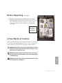
It’s a good idea to record the model and serial number(s) of your equipment and
the date you received it in the User Guide. Our service department uses this information, along with the manual number, to provide help for the specific equipment
you installed.
Please record your equipment’s
model and serial number(s) and
the date you received it in the
spaces provided.
Please keep this User Guide and all manuals, engineering prints and parts lists
together for documentation of your equipment.
Date:
Manual Number: UGD028-0107
Serial Number(s):
Model Number(s):
* Display Firmware Version:
✐
* Control Firmware Version:
* NOTE: Displayed upon initialization, during power up, or on a data tag
inside the door.
DISCLAIMER: The Conair Group, Inc., shall not be liable for errors contained in this User Guide or
for incidental, consequential damages in connection with the furnishing, performance or use of
this information. Conair makes no warranty of any kind with regard to this information, including,
but not limited to the implied warranties of merchantability and fitness for a particular purpose.
Copyright 2007 l The Conair Group l All rights reserved
Ta b l e o f C o n t e n t s
1-1 I n t r o d u c t i o n
Purpose of the user guide . . . . . . . . . . . . . . . . . . . . . . . . . . . . . . . . 1-2
How the guide is organized . . . . . . . . . . . . . . . . . . . . . . . . . . . . . . 1-2
Using the Carousel Plus W Series as a central dryer . . . . . . . . . . . . 1-3
Your responsibilities as a user . . . . . . . . . . . . . . . . . . . . . . . . . . . . . 1-3
ATTENTION: Read this so no one gets hurt . . . . . . . . . . . . . . . . . . . 1-4
How to use the lockout device . . . . . . . . . . . . . . . . . . . . . . . . . . . . 1-6
2-1 D e s c r i p t i o n
What is the Carousel Plus W Series Dryer? . . . . . . . . . . . . . . . . . . .2-2
Typical applications . . . . . . . . . . . . . . . . . . . . . . . . . . . . . . . . . . . . .2-2
How it works . . . . . . . . . . . . . . . . . . . . . . . . . . . . . . . . . . . . . . . . . .2-4
Specifications: Carousel Plus W Series Dryer. . . . . . . . . . . . . . . . . . 2-6
Carousel Plus W Series Dryer options . . . . . . . . . . . . . . . . . . . . . . . 2-7
3-1 I n s t a l l a t i o n
Unpacking the boxes . . . . . . . . . . . . . . . . . . . . . . . . . . . . . . . . . . . 3-2
Preparing for installation . . . . . . . . . . . . . . . . . . . . . . . . . . . . . . . . . 3-4
Positioning the dryer on the floor . . . . . . . . . . . . . . . . . . . . . . . . . . 3-5
Removing the cable tie from the desiccant wheel . . . . . . . . . . . . . . 3-5
Connecting the main power . . . . . . . . . . . . . . . . . . . . . . . . . . . . . . 3-6
Connecting the process RTD probe . . . . . . . . . . . . . . . . . . . . . . . . . 3-7
Connecting the setback RTD probe (Optional) . . . . . . . . . . . . . . . . . 3-7
Checking for proper air flow . . . . . . . . . . . . . . . . . . . . . . . . . . . . . . 3-8
Connecting the air hoses. . . . . . . . . . . . . . . . . . . . . . . . . . . . . . . . 3-11
Connecting the dryer to the hopper. . . . . . . . . . . . . . . . . . . . . . . . 3-11
Ta b l e o f C o n t e n t s l i
Connecting air hose adapters . . . . . . . . . . . . . . . . . . . . . . . . . . . . 3-12
Connecting the aftercooler . . . . . . . . . . . . . . . . . . . . . . . . . . . . . . 3-13
Mounting a loader on the hopper . . . . . . . . . . . . . . . . . . . . . . . . . 3-14
Testing the installation . . . . . . . . . . . . . . . . . . . . . . . . . . . . . . . . . 3-14
4-1 O p e r a t i o n
Carousel Plus W Series Dryer: control panel DC-1. . . . . . . . . . . . . . 4-2
Carousel Plus W Series Dryer control functions . . . . . . . . . . . . . . . . 4-3
Control function flow chart . . . . . . . . . . . . . . . . . . . . . . . . . . . . . . . 4-3
Control function descriptions. . . . . . . . . . . . . . . . . . . . . . . . . . . . . . 4-5
To start drying. . . . . . . . . . . . . . . . . . . . . . . . . . . . . . . . . . . . . . . . 4-19
To stop drying . . . . . . . . . . . . . . . . . . . . . . . . . . . . . . . . . . . . . . . . 4-20
Using the auto start countdown function . . . . . . . . . . . . . . . . . . . . 4-21
How to disable the auto start on the DC-1 control. . . . . . . . . . . . . 4-21
Setting high setpoint limits . . . . . . . . . . . . . . . . . . . . . . . . . . . . . . 4-22
Using dewpoint control . . . . . . . . . . . . . . . . . . . . . . . . . . . . . . . . . 4-23
Using the setback feature (Optional) . . . . . . . . . . . . . . . . . . . . . . . 4-24
Setback feature guidelines (Optional) . . . . . . . . . . . . . . . . . . . . . . 4-25
5-1 M a i n t e n a n c e
Preventative maintenance schedule . . . . . . . . . . . . . . . . . . . . . . . . 5-2
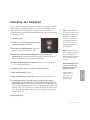
Checking the dewpoint . . . . . . . . . . . . . . . . . . . . . . . . . . . . . . . . . . 5-3
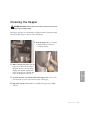
Cleaning the hopper . . . . . . . . . . . . . . . . . . . . . . . . . . . . . . . . . . . . 5-5
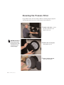
Cleaning the process filter. . . . . . . . . . . . . . . . . . . . . . . . . . . . . . . . 5-6
Cleaning the regeneration filter . . . . . . . . . . . . . . . . . . . . . . . . . . . . 5-8
Cleaning the aftercooler coils . . . . . . . . . . . . . . . . . . . . . . . . . . . . 5-10
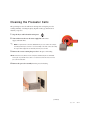
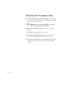
Cleaning the precooler coils . . . . . . . . . . . . . . . . . . . . . . . . . . . . . 5-12
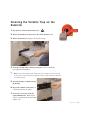
Cleaning the volatile trap on the demister . . . . . . . . . . . . . . . . . . . 5-12
Inspecting hoses and gaskets . . . . . . . . . . . . . . . . . . . . . . . . . . . . 5-12
i i l Ta b l e o f C o n t e n t s
6-1 Tr o u b l e s h o o t i n g
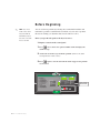
Before beginning. . . . . . . . . . . . . . . . . . . . . . . . . . . . . . . . . . . . . . . 6-2
A few words of caution . . . . . . . . . . . . . . . . . . . . . . . . . . . . . . . . . 6-3
DIAGNOSTICS
How to identify the cause of a problem . . . . . . . . . . . . . . . . . . . . . 6-4
Alarms . . . . . . . . . . . . . . . . . . . . . . . . . . . . . . . . . . . . . . . . . . . . . 6-5
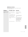
Dewpoint troubleshooting . . . . . . . . . . . . . . . . . . . . . . . . . . . . . . . 6-24
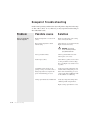
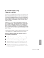
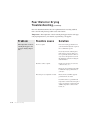
Poor material drying troubleshooting. . . . . . . . . . . . . . . . . . . . . . . 6-25
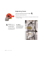
REPAIR
Replacing fuses. . . . . . . . . . . . . . . . . . . . . . . . . . . . . . . . . . . . . . . 6-30
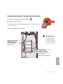
Checking heater solid state relays. . . . . . . . . . . . . . . . . . . . . . . . . 6-31
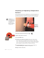
Checking or replacing temperature sensors . . . . . . . . . . . . . . . . . 6-32
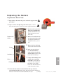
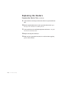
Replacing the heaters
Regeneration heater tube . . . . . . . . . . . . . . . . . . . . . . . . . . 6-33
Process heater tube . . . . . . . . . . . . . . . . . . . . . . . . . . . . . . 6-35
Replacing the desiccant wheel . . . . . . . . . . . . . . . . . . . . . . . . . . . 6-37
Replacing the desiccant wheel motor . . . . . . . . . . . . . . . . . . . . . . 6-38
A
Appendix
We’re here to help . . . . . . . . . . . . . . . . . . . . . . . . . . . . . . . . . . . . . A-1
How to contact customer service . . . . . . . . . . . . . . . . . . . . . . . . . . A-1
Before you call... . . . . . . . . . . . . . . . . . . . . . . . . . . . . . . . . . . . . . . A-1
Equipment guarantee . . . . . . . . . . . . . . . . . . . . . . . . . . . . . . . . . . A-2
Performance warranty . . . . . . . . . . . . . . . . . . . . . . . . . . . . . . . . . . A-2
Warranty limitations . . . . . . . . . . . . . . . . . . . . . . . . . . . . . . . . . . . . A-2
B
Appendix
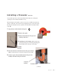
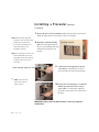
Installing a precooler (Optional) . . . . . . . . . . . . . . . . . . . . . . . . . . . B-1
Ta b l e o f C o n t e n t s l i i i
C
Appendix
Cleaning the precooler coils . . . . . . . . . . . . . . . . . . . . . . . . . . . . . . C-1
D
Appendix
Cleaning the volatile trap on the demister (Optional) . . . . . . . . . . . D-1
i v l Ta b l e o f C o n t e n t s
SECTION
1
Purpose of the user guide . . . . . . . . . . . . . . 1-2
How the guide is organized . . . . . . . . . . . . . 1-2
Using the Carousel Plus W Series as
a central dryer . . . . . . . . . . . . . . . . . . 1-3
Yo u r r e s p o n s i b i l i t i e s a s a u s e r . . . . . . . . . . . 1 - 3
AT T E N T I O N :
Read this so no one gets hurt . . . . . . . . 1-4
How to use the lockout device . . . . . . . . . . . 1-6
Introduction l 1-1
1
Introduction
Introduction
Purpose of the User Guide
This User Guide describes the Conair Carousel Plus W Series Dryers and
explains step-by-step how to install, operate, maintain, and repair this
equipment.
Before installing this product, please take a few moments to read the User
Guide and review the diagrams and safety information in the instruction
packet. You also should review manuals covering associated equipment in
your system. This review won’t take long, and it could save you valuable
installation and operating time later.
How the Guide is Organized
Symbols have been used to help organize the User Guide and call your
attention to important information regarding safe installation and operation.
Symbols within triangles warn of conditions that could be hazardous to users or
could damage equipment. Read and take precautions before proceeding.
1
Numbers indicate tasks or steps to be performed by the user.
◆
A diamond indicates the equipment’s response to an action performed by the user.
❒
An open box marks items in a checklist.
•
A circle marks items in a list.
✒
✐
1-2 l Introduction
Indicates a tip. A tip is used to provide you with a suggestion that will help you with
the maintenance and the operation of this equipment.
Indicates a note. A note is used to provide additional information about the steps
you are following throughout the manual.
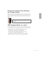
Using the Carousel Plus W Series
as a Central Dryer
This box will contain information or highlight system differences particular to the application of the W series dryer as a
central dryer.
Yo u r R e s p o n s i b i l i t y a s a U s e r
You must be familiar with all safety procedures concerning installation, operation and maintenance of this equipment. Responsible safety procedures include:
• Thorough review of this User Guide, paying particular attention
to hazard warnings, appendices and related diagrams.
• Thorough review of the equipment itself, with careful attention
to voltage sources, intended use and warning labels.
• Thorough review of instruction manuals for associated equipment.
• Step-by-step adherence to instructions outlined in this User Guide.
Introduction l 1-3
1
Introduction
This manual incorporates the information necessary to use the Conair W Series
Dryer as a central dryer. Throughout this manual, information particular to central dyer application of the W series dryer is called out by the following treatment.
AT T E N T I O N :
Read this so no one gets hurt
We design equipment with the user’s safety in mind. You can avoid the potential
hazards identified on this machine by following the procedures outlined below and
elsewhere in the User Guide.
WA R N I N G : I m p r o p e r i n s t a l l a t i o n , o p e r a t i o n , o r
servicing may result in equipment damage or
p e r s o n a l i n j u r y.
This equipment should be installed, adjusted, and serviced by qualified
technical personnel who are familiar with the construction, operation,
and potential hazards of this type of machine.
All wiring, disconnects, and fuses should be installed by qualified electrical technicians in accordance with electrical codes in your region.
Always maintain a safe ground. Do not operate the equipment at power
levels other than what is specified on the machine serial tag and data
plate.
WA R N I N G : Vo l t a g e h a z a r d
This equipment is powered by three-phase alternating current,
as specified on the machine serial tag and data plate.
A properly sized conductive ground wire from the incoming power
supply must be connected to the chassis ground terminal inside the
electrical enclosure. Improper grounding can result in severe personal
injury and erratic machine operation.
Always disconnect and lock out the incoming main power source before
opening the electrical enclosure or performing non-standard operating
procedures, such as routine maintenance. Only qualified personnel
should perform troubleshooting procedures that require access to the
electrical enclosure while power is on.
(continued)
1-4 l Introduction
AT T E N T I O N :
Read this so no one gets hurt
(continued)
CA U T I O N : H o t S u r fa c e s .
Always protect yourself from hot surfaces inside the dryer and hopper.
Also exercise caution around exterior surfaces that may become hot
during use. These include the hopper door frame, the exterior of an
uninsulated hopper, the return air hose and the dryer’s process filter
housing and moisture exhaust outlet.
WA R N I N G : D o n o t p l a c e a e r o s o l , c o m p r e s s e d
gas or flammable materials on or near this
equipment.
The hot temperatures associated with the drying process may cause
aerosols or other flammable materials placed on the dryer or hopper to
explode.
Introduction l 1-5
1
Introduction
We design equipment with the user’s safety in mind. You can avoid the potential
hazards identified on this machine by following the procedures outlined below and
elsewhere in the User Guide.
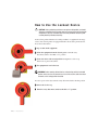
How to Use the Lockout Device
CAUTION: Before performing maintenance or repairs on this product, you should
disconnect and lockout electrical power sources to prevent injury from unexpected
energization or start-up. A lockable device has been provided to isolate this product from potentially hazardous electricity.
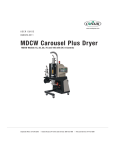
Lockout is the preferred method of isolating machines or equipment from energy
sources. Your Conair product is equipped with the lockout device pictured below.
To use the lockout device:
1 Stop or turn off the equipment.
2 Isolate the equipment from the electric power. Turn the rotary
disconnect switch to the OFF, or “O” position.
3 Secure the device with an assigned lock or tag. Insert a lock or tag
in the holes to prevent movement.
4 The equipment is now locked out.
WARNING: Before removing lockout devices and returning switches to the ON
position, make sure that all personnel are clear of the machine, tools have been
removed, and all safety guards reinstalled.
To restore power to the dryer, turn the rotary disconnect back to the ON position:
1 Remove the lock or tag.
2 Turn the rotary disconnect switch to the ON or “l” position.
1-6 l Introduction
SECTION
2
What is the Carousel Plus W series dryer? . . . 2-2
Ty p i c a l a p p l i c a t i o n s . . . . . . . . . . . . . . . . . . 2 - 2
How it works . . . . . . . . . . . . . . . . . . . . . . 2-4
Specifications: Carousel Plus W Series
Dryer . . . . . . . . . . . . . . . . . . . . . . . . . 2-6
Carousel Plus W Series Dryer options . . . . . . 2-7
Description l 2-1
2
Description
Description
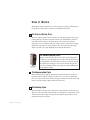
What is the Carousel Plus W Series
Dryer?
The Carousel Plus W Series Dehumidifying Dryer produces hot, low-dewpoint air
that removes moisture from hygroscopic plastics. The dryer pulls warm, moist air
from a drying hopper and circulates it through a dehumidifying desiccant wheel.
The dryer then heats the air to the drying temperature you selected and circulates it
through the material in the hopper.
The dryer’s closed-loop design ensures a continuous supply of hot, dehumidified
air while preventing contamination from moisture in the plant.
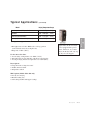
Ty p i c a l A p p l i c a t i o n s
1 Dryer on the floor; hopper on the throat.
2 Hopper on a floor stand; the dryer next to it.
3 Dryer and hopper on a mobile floor stand (MDC version 150 and 200 only).
4 Central dryer with ResinWorks system.
The W dryer can be used successfully in applications that require:
• A contamination-free drying environment.
• Drying temperatures within the ranges shown in the following table:
(continued)
2-2 l Description
Ty p i c a l A p p l i c a t i o n s
Model
(continued)
Drying Temperature Range
100° - 150°F {38° - 66°C}
Standard
150° - 240°F {66° - 116°C}
High heat (with aftercooler)*
150° - 375°F {66° - 191°C}
Low-high (with aftercooler & precooler)*
100° - 375°F {38° - 191°C}
* See page 3-13, Appendix B
(some materials can be run at a higher rate).
• Dewpoints of -40°F {-40°C}.
Use the aftercooler when:
• You are drying at temperatures over 240°F {116°C}.
• Throughput rates are less than 50% of the dryer’s rated capacity.
• You are pre-drying material at temperatures over 150°F {66°C}.
When supplied for central drying
applications, the W series dryer
is not equipped with a process
heater. Therefore, as a central
dryer, the W dryer will only supply dry air to the hoppers.
Dryer Options
• Dewpoint monitor / dewpoint control
• Audible and visual alarm
• Temperature setback
MDC Options (Models 150 & 200 only)
• Non dry air conveying
• Machine loading only
• Self-loading (machine and hopper loading)
Description l 2-3
2
• Throughput rates of 150 to 400 lbs {68 to 149 kg} per hour
Description
Low temperature (with precooler)*
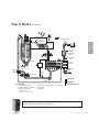
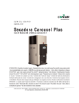
H o w I t Wo r k s
The W dryer achieves continuous, closed loop drying by passing air simultaneously through two heaters and a continuously rotating desiccant wheel.
THE PROCESS (DRYING) CYCLE
The process blower pulls moist air from the top of the drying hopper. The air passes through the process filter (and optional aftercooler, if installed) into the desiccant wheel, where moisture is removed. The now dry air moves through the
optional precooler (if installed) and process heater, where it is heated to the drying
temperature selected by the operator. The hot, dry air is delivered to the hopper
where a spreader cone evenly distributes the air through the material.
THE PROCESS (DRYING) CYCLE
The process blower pulls moist air from the top of the drying hopper. The air passes through the process filter (and optional aftercooler, if installed) into the wheel, where moisture is removed. The dry
air is delivered to the hopper (after it passes through the optional
precooler, if installed) where a spreader cone evenly distributes the
air through the material.
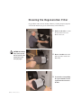
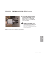
The Regeneration Cycle
The regeneration blower pulls air through the regeneration filter into the dryer’s
regeneration heater. The air is heated to 350° F {177° C} before it is pushed into
the “wet” section of the wheel. The hot air purges moisture from the desiccant. The
moist air is blown out the exhaust at the back of the dryer.
The Cooling Cycle
Regenerated desiccant must be cooled before it rotates back into the process cycle.
The process blower pushes a small amount of air through the cooling section of the
desiccant wheel. The cooling air then passes through the optional aftercooler, if
installed, and repeats the circuit.
2-4 l Description
H o w I t Wo r k s
(continued)
4
1
PROCESS
PROCESS PROTECTION
RTD
RTD
PROCESS
HEATER BOX
7
6
REGENERATION
BLOWER
HIGH TEMP
SHUTOFF
REGENERATION
HEATER
5
REGENERATION
RTD
HOPPER
DESICCANT
WHEEL
2
3
REGENERATION
OUTLET
RTD
RETURN
AIR
FILTER
AFTERCOOLER
RETURN
AIR
RTD
PROCESS
PROCESS
BLOWER
COOLING
DRYER OPTIONS
1 SET BACK TEMPERATURE
4 PHASE ROTATION PROTECTION
2 DEWPOINT MONITOR / CONTROL
3 PROCESS FILTER STATUS
5 PRECOOLER
6 ALARM BELL†
*
7 ALARM LIGHT
†
REGENERATION
*† Standard on MDC only
Standard on some DC-1 models
The components identified by this type of box in the drawing are not supplied with the
W dryer when it is configured as a central dryer.
Description l 2-5
2
REGENERATION
AIR FILTER
Description
HIGH TEMP
SHUTOFF
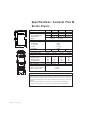
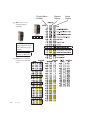
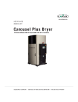
Specifications: Carousel Plus W
Series Dryers
A
D
MODEL
W150
W200
W300
W400
Performance characteristics (with full hopper)
Air flow {SCFM}*
75
100
150
200
Air flow {ACFM @ 250°F}*
101
134
201
268
Drying temperature
All models 100 - 375°F {38 - 191°C} with options
dewpoint
All models
-40°F {-40°C}
Dimensions inches {cm}
A - Height
70.4 {178.8}
B - Overall width
29 {73.7}
C - Control width
24 {61.0}
D - Depth
51.5 {130.8}
Control depth
8 {20.3}
Outlet/inlet tube size OD
2.5
5
5
5
Weight lbs {kg}
Standard Dryer Installed
600 {272}
660 {300}
710 {322}
760 {345}
Voltage - Total Amps
230 V/3 phase/60 Hz
47.1
61.4
67
N/A
400 V/3 phase/50 Hz
25.8
34
38.5
63.6
460 V/3 phase/60 Hz
23.6
30.7
33.5
55.3
575 V/3 phase/60 Hz
18.9
24.7
26.8
44.3
Total kilowatts kW {BTU/min}
6.2 {353}
8 {455}
11 {625}
14 {800}
Water requirements {for optional aftercooler or precooler}
Recommended temperature*
45° - 85°F
Water flow gal./min. {liters/min.}
3 {11.4}
Water connections NPT
C
B
3/4 in. NPT
SPECIFICATION NOTES:
* The term SCFM stands for Standard Cubic Feet Per Minute, referenced to a pre-specified pressure, temperature
and relative humidity. In most cases, SCFM is referenced to 14.7 PSIA 68° F and 36% relative humidity. ACFM
stands for Actual Cubic Feet Per Minute, and must be supplied with a temperature reference, due to the change
in air density with temperature. Because dryers operate at a relatively low pressure the effects on air density are
negligible.
† Dryers running at 50 HZ will have 17% less airflow, and a 17% reduction in material throughput.
Specifications may change without notice. Consult a Conair representative for the most current information.
TPDS018-0705-REV
2-6 l Description
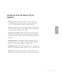
Carousel Plus W Series Dryer
Options
• Volatile trap (only in conjunction with aftercooler) - The volatile trap is
recommended if drying materials that produce volatile that condense into a
waxy or oily residue and/or if the material contains excessive fines.
cant wheel and before the process heater, enables the dryer to control temperatures at low setpoints, (100º - 150ºF {38º - 66ºC})
• Dewpoint monitor/dewpoint control - The dewpoint monitor/dewpoint control allows the operator to monitor and control the performance of the dryer’s
dewpoint level, making energy savings possible by reducing the regeneration
temperature.
• Temperature setback - The temperature setback automatically reduces the
drying temperature to a lower standby mode when the machine throughput is
reduced or stopped, helping to minimize over drying material
• Audible/Visual alarms - The audible and visual alarms are a combination of a
blinking red alarm light and a horn that alerts the operator to a shutdown alarm.
• Filter check - The filter check sensor will activate a passive P10 alarm or a
shutdown A29 alarm when the process filter is clogged or needs to be replaced.
Description l 2-7
2
Description
• Precooler - The precooler reduces the temperature of air flow after the desic-
2-8 l Description
SECTION
3
Installation
Unpacking the boxes . . . . . . . . . . . . . . . . . 3-2
Preparing for installation . . . . . . . . . . . . . . 3-4
Removing the cable tie from the
desiccant wheel . . . . . . . . . . . . . . . . . 3-5
Connecting the main power . . . . . . . . . . . . . 3-6
C o n n e c t i n g t h e p r o c e s s RT D p r o b e . . . . . . . . 3 - 7
C o n n e c t i n g t h e s e t b a c k RT D p r o b e ( O p t i o n a l ) . 3 - 7
Checking for proper air flow . . . . . . . . . . . . 3-8
Connecting the air hoses . . . . . . . . . . . . . 3-11
Connecting the dryer to the hopper . . . . . . 3-11
Connecting air hose adapters . . . . . . . . . . 3-12
Connecting the aftercooler . . . . . . . . . . . . 3-13
Mounting a loader on the hopper . . . . . . . . 3-14
Te s t i n g t h e i n s t a l l a t i o n . . . . . . . . . . . . . . . 3 - 1 4
Installation l 3-1
3
Installation
Po s i t i o n i n g t h e d r y e r o n t h e f l o o r . . . . . . . . . 3 - 5
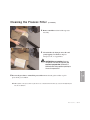
Unpacking the Boxes
The Carousel Plus W Series Dryer comes in one to four boxes, depending on the
model and options ordered. The boxes could include (depending on the options
selected):
• Carousel Plus W Series Dryer
• Delivery air hose - 10 ft {3.05 m} - Insulated with High Heat option.
• Return air hose - 10 ft {3.05 m}
• Process RTD
• Setback RTD (optional)
• User manual
1 Carefully remove the dryer and components from their shipping containers.
Note that the dryer is secured to its shipping container with
straps that pass through the bottom of the dryer frame.
2 Remove all packing material, protective paper, tape and plastic.
3 Open the side panel and remove the cable tie securing the desiccant wheel.
See Installation section entitled, Removing the cable tie from the desiccant
wheel.
4 Carefully inspect all components to make sure no damage occurred during
shipping, and that you have all the necessary hardware.
3-2 l Installation
Unpacking the Boxes
(continued)
5 Take a moment to record serial numbers and electrical power specifications in the blanks provided on the back of the User Guide’s title page. The
information will be helpful if you ever need service or parts.
6 You are now ready to begin installation.
Follow the preparation steps on the next page, then choose one of the four
mounting options:
• Dryer on the floor; hopper on a floor stand (see page 3-5).
• Dryer on the floor; hopper mounted to the machine stand.
• Dryer and hopper on a mobile floor stand.
• Central dryer, with ResinWorks system.
NOTE: Conair also sells an MDC (dryer and hopper on a mobile floor stand with conveying capabilities) version of this dryer in the 150 and 200 Models. Contact Conair Sales
for additional information.
Installation l 3-3
3
Installation
✐
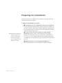
Preparing for Installation
The Carousel Plus W Series Dryer is easy to install if you plan the location and
prepare the mounting area properly.
1 Make sure the mounting area provides:
❒ A grounded power source supplying the voltage and correct current
for your dryer model. Check the dryer’s serial tag for the correct amps, voltage, phase, and cycles. Field wiring should be completed by qualified personnel to the planned location for the dryer. All electrical wiring should comply
with your region’s electrical codes.
✒
Material and conveying lines
installed. If you plan to use
vacuum or compressed air
loaders to fill the hopper,
install conveying lines to the
drying hopper location.
3-4 l Installation
❒ A source of water, if you have an aftercooler and/or optional
precooler. The W dryer’s aftercooler and optional precooler require 3
gals./min. {11.4 liters/min.} tower, city, or chiller water at temperatures of
45° to 85°F {7° to 29°C}. Pipe should be run to the planned dryer location.
Use flexible hose to connect the water pipes to the aftercooler and/or optional
precooler.
❒ Minimum clearance for safe operation and maintenance.
You should maintain 24 in. {61 cm} clearance on all sides of the dryer.
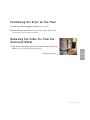
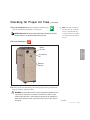
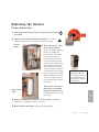
Po s i t i o n i n g t h e D r y e r o n t h e F l o o r
1 Lift the dryer from the shipping container using a fork truck.
2 Position the dryer on the floor near the processing machine. Make sure the
location allows for the connection of all hoses.
R e m o v i n g t h e C a b l e Ti e f r o m t h e
Desiccant Wheel
1 Open the dryer side panels and remove the cable tie securing the desiccant
wheel, if it was not done while unpacking the dryer.
Installation l 3-5
3
Installation
Desiccant cable tie
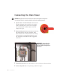
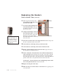
C o n n e c t i n g t h e M a i n Po w e r
CAUTION: Always disconnect and lock out the main power sources before making electrical connections. Electrical connections should be made only by qualified personnel.
1 Open the dryer’s electrical enclosure. Turn the disconnect dial on the dryer door to the Off or “O” position.
Lock out the main power (see Page 1-6 for complete
lock out information). Turn the captive screw, and
swing the door open.
2 Insert the main power wire through the knockout in the
side of the enclosure or the rear of the dryer. (The
dryer’s electrical wire connection location was a factory
option and may be connected through the front or the
rear of the dryer.) Secure the wire with an appropriate
strain relief.
IMPORTANT: Always refer to the
wiring diagrams that came with
your dryer before making electrical
connections.
3 Connect the power wires to the three terminals at the top of the power disconnect holder.
4 Connect the ground wire to the ground lug as shown in the photo.
3-6 l Installation
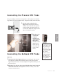
C o n n e c t i n g t h e P r o c e s s RT D P r o b e
The process RTD probe monitors the temperature of the drying air as it enters the
hopper. If the probe is not installed correctly, temperature readings will be inaccurate.
1 Insert the probe at the inlet to the
hopper. The end of the probe must not
touch the walls of the inlet. The tip of the
probe should be approximately in the center of the tube. Tighten the compression fittings to lock the probe in place.
2 Plug the probe’s
C o n n e c t i n g t h e S e t b a c k RT D P r o b e
(Optional)
When configured as
a central dryer, monitoring the drying air
temperature is not
necessary since there
is no process heater
in the system.
Therefore, installation and connection
of the RTD probe
and/or setback probe
is not applicable.
1 Insert the probe in the hopper outlet at the top of the hopper. The end of the
probe must not touch the walls of the inlet. The tip of the probe should be
approximately in the center of the tube. Tighten the compression fittings to lock
the probe in place.
2 Plug the probe’s cable into the receptacle labeled setback on the left side of
the electrical enclosure. Hand tighten the connector. Coil any excess cable
and secure it with a wire tie.
Installation l 3-7
3
Process RTD
cable into the
receptacle
labeled process
on the left side of
the electrical
enclosure. Hand
tighten the connector. Coil any
excess cable and
secure it with a
wire tie.
Installation
Setback RTD
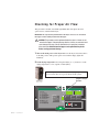
Checking for Proper Air Flow
This procedure is needed on W-50 through 100 models if the phase detection
option was not ordered with the dryer.
IMPORTANT: This step must be performed before the dryer’s air hoses are connected to
the hopper or before loading material into the hopper.
CAUTION: This procedure must be performed before the dryer’s air hoses are connected to the hopper. Performing this step after the air hoses are connected could
cause damage to the dryer if the air flow direction is incorrect due to improper
phase connection. Material from the hopper can be pulled into the process
heater, causing permanent damage.
1 Turn on the main power to the dryer. Make sure the dryer’s disconnect dial is
in the ON position. This powers up the control and the display lights will
illuminate.
2 Set the drying temperature. Press Setpoint Adjust (+) or (-) buttons to set the
drying temperature to a low setpoint of 150ºF {66ºC}.
When configured as a central dryer, the drying temperature can
not be set since there is no process heater in the system.
Setpoint Adjust
Buttons
Shutdown Alarms
A1
Process High Temp
A2
Process Loop Break
A3
Process Heater High Temp
A4
Regen Heater High Temp
A7
Return Air High Temp
A49 Process Protection High Temp
A53 Process Blower Overload
A55 Wheel Rotation Failure
Passive Alarms
P1
Process Temp Deviation
P3
Regen Temp Deviation
P5
Return Air Mid High Temp
P17 MDC Conveying Demand
3-8 l Installation
1
2
3
4
5
6
7
8
Process Temp.
Regen. Temp.
Return Air Temp.
Auto Start
Load Time (MDC)
Activate Setback Temp.
Setback Temp.(Process)
Dewpoint
Process Blower
Regen. Blower
Auto Start
Process Heater
Regen. Heater
Dewpoint Control
Conveying Blower
Set-Back Temp.
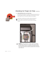
Checking for Proper Air Flow
(continued)
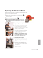
3 Press the START button. Hold your hand near the delivery air
Start
outlet. You should feel air blowing out of the outlet.
✐
NOTE: If the dryer is running for
more than 20 to 30 seconds, the
Process Loop Break alarm may
CAUTION: Hot surface Do not place your hand directly on the delivery air outlet.
The outlet and the air can get hot enough to burn your hand.
occur because the Process RTD is
not seeing the expected temperature rise.
4 Press the STOP button.
Stop
Dry Delivery
Air
Moisture
Exhaust
5 If air flow is incorrect disconnect power, follow proper lockout procedures and
swap any 2 of the 3 main power wires.
WARNING: All wiring, disconnects, and fuses should be installed by qualified electrical technicians in accordance with electrical codes in your
region. Always maintain a safe ground. Do not operate the equipment at
power levels other than what is specified on the machine serial tag and
data plate.
(continued)
Installation l 3-9
3
Installation
Return
Air Inlet
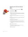
Checking for Proper Air Flow
✐
(continued)
INSTALLATION NOTE: Models 150, 200, 300, and 400
These models use a three-phase process blower. If the dryer shuts down and a Process
Loop Break shutdown alarm (A2) is indicated within the first few minutes of operation,
check for proper air flow or check the Process RTD for proper installation.
If the air flow is reversed, the process blower is turning in the wrong direction. Turn off and lock out the main power source. Open the electrical
enclosure and reverse any two leads connecting the main power supply to
the dryer.
LEADS
WARNING: All wiring, disconnects, and fuses should be installed by
qualified electrical technicians in accordance with electrical codes in
your region. Always maintain a safe ground. Do not operate the equipment at power levels other than what is specified on the machine serial
tag and data plate.
3-10 l Installation
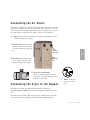
Connecting the Air Hoses
Using the two flexible hoses provided, connect the inlets and outlets of the drying hopper to the dryer. If you have positioned the dryer on the floor or mounted it to an optional floor stand, make sure the dryer is located as close as possible to the hopper to reduce heat loss. (10 ft {3.05 m} of hose supplied)
✐
NOTE: If you have ordered an insulated hose, it should be installed between the dryer
outlet and the hopper inlet, see step 2.
1 Attach one hose from the return
Return
Air Inlet
Dry
Delivery
Air
2 Attach one hose from the delivery air outlet of the dryer to the
delivery air inlet of the hopper.
3 Secure hoses with clamps.
The hose clamp should be secured at
least 1/4 in. {6.35 mm} from the end of
the inlet or outlet tube.
✐
NOTE: Do not allow the
flexible hoses to kink or
Connecting the Dryer to the Hopper
crimp.
W 150 has a 2 1/2 inch {63.5 mm} inlet and outlet hose connections.
W 200, W 300 and W 400 have a 5 inch {127 mm} inlet and outlet hose connections.
If your dryer hose connection and your hopper hose connection are not the same
size, you will need a hose adapter. Contact Conair Parts 1-800-458-1960.
Installation l 3-11
3
Installation
air inlet of the dryer to the return
air outlet from the top of the hopper.
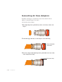
Connecting Air Hose Adapters
Depending on the hopper you purchased you may need to install an air hose
adapter to connect the hopper to your dryer.
To connect the air hose adapter:
1 Place high temperature gasket half way down over the dryer outlet to the
hopper.
2 Attach the hopper inlet hose over the adapter, secure with clamp.
Dryer inlet/outlet
connection
3 Place hose adapter inside high temperature gasket flush to the dryer outlet,
secure with pressure clamp.
Pressure clamp
3-12 l Installation
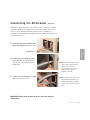
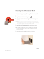
Connecting the Aftercooler
(Optional)
The aftercooler and optional precooler require a source of city, tower, or chiller
water and a discharge or return line. You can use water at temperatures of 45 to
85°F {7 to 29°C}. But the water flow should be at least 3 gal/min {11.4
liters/min}. See Appendix B for installation and water connection instructions for
the optional precooler.
1 Secure the aftercooler assembly in the
aftercooler housing using the six screws.
2 Connect the water supply line to the
aftercooler inlet. If a manual shut off
valve is used, it should be mounted on
the inlet line.
✒ TIP: Make the water supply and discharge / return connections with
flexible hoses at least 24 in.
{61 cm} long. This allows you to
easily remove the aftercooler
assembly for cleaning.
3 Connect the water discharge or return
line to the aftercooler outlet.
✒ TIP: If an optional flow control is also
being installed with the aftercooler,
the manual shut off valve should be
installed on the inlet line for the flow
control.
IMPORTANT: Turn the water off when the dryer is not in use to prevent
condensation.
Installation l 3-13
3
Installation
Aftercooler
✐
NOTE: Check to make
sure cable tie has been
removed from desic-
✐
cant wheel.
NOTE: If A2 (Process
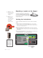
Mounting a Loader on the Hopper
If you have a Conair loader or vacuum receiver,
you can use the flange and mounting clips provided on the top of the hopper. Refer to the manuals
that came with your receiver or loader for detailed
installation instructions.
Loop Break) alarm
occurs, blower rotation
may be incorrect or
Te s t i n g t h e I n s t a l l a t i o n
Process RTD is
installed incorrectly.
You have completed the installation. Now it’s time to make sure everything
works.
1 Make sure there is no material in the hopper. If you have mounted a
loader or vacuum receiver on the hopper, disconnect the material inlet hose
at the source or turn the loader off.
2 Turn on the main power to the dryer. Make sure the dryer’s disconnect
dial is in the ON position. This powers up the control and the display lights
will illuminate.
3 Set the drying temperature. Press Setpoint Adjust (+) or (-) buttons to set
the drying temperature to a low setpoint (150ºF {66ºC}).
When configured
as a central dryer,
the drying temperature can not be
set since there is
no process heater
in the system.
Shutdown Alarms
A1
Process High Temp
A2
Process Loop Break
A3
Process Heater High Temp
A4
Regen Heater High Temp
A7
Return Air High Temp
A49 Process Protection High Temp
A53 Process Blower Overload
A55 Wheel Rotation Failure
Passive Alarms
P1
Process Temp Deviation
P3
Regen Temp Deviation
P5
Return Air Mid High Temp
P17 MDC Conveying Demand
1
2
3
4
5
6
7
8
Process Temp.
Regen. Temp.
Return Air Temp.
Auto Start
Load Time (MDC)
Activate Setback Temp.
Setback Temp.(Process)
Dewpoint
Process Blower
Regen. Blower
Auto Start
Process Heater
Regen. Heater
Dewpoint Control
Conveying Blower
Set-Back Temp.
Setpoint
adjustment
buttons
3-14 l Installation
Te s t i n g t h e I n s t a l l a t i o n
4 Press the START button.
(continued)
Start
If everything is installed correctly:
• The green light on the start button will illuminate.
• The process and regeneration blowers and LEDS will turn on.
• The process and regeneration heaters and LEDS will turn on.
• The desiccant wheel starts turning.
5 Press the STOP button.
Stop
• The green light on the start button will illuminate.
• The process and regeneration blowers turn on and the display
LEDS will illuminate.
• The regeneration heater turns on and the display LED will
•
illuminate.
The desiccant wheel starts turning.
6 The test is over. If the dryer performed the normal operating sequences as outlined, you can load the hopper and begin operation. If it did not, refer to the
Troubleshooting section of the User Guide.
Installation l 3-15
3
Installation
If everything is installed correctly:
• The blowers will continue running as needed to cool the heaters
(until both heaters are less than 150°F {66°C}).
3-16 l Installation
SECTION
4
Operation
Carousel Plus W Series Dryer:
control panel DC-1 . . . . . . . . . . . . . . . . . . 4-2
Carousel Plus W Series Dryer
control functions . . . . . . . . . . . . . . . . . 4-3
Control function descriptions . . . . . . . . . . . 4-5
To s t a r t d r y i n g . . . . . . . . . . . . . . . . . . . . 4 - 1 9
To s t o p d r y i n g . . . . . . . . . . . . . . . . . . . . . 4 - 2 0
Using the auto start countdown function . . . 4-21
How to disable the auto start on
the DC-1 control . . . . . . . . . . . . . . . . 4-21
Setting high setpoint limit. . . . . . . . . . . . . 4-22
Using dewpoint control . . . . . . . . . . . . . . . 4-23
Using the setback feature (Optional) . . . . . . 4-24
Setback feature guidelines (Optional. . . . . . 4-25
Operation l 4-1
4
Operation
Control function flow chart . . . . . . . . . . . . . 4-3
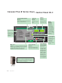
C a r o u s e l P l u s W S e r i e s D r y e r : C o n t r o l Pa n e l D C - 1
Increment/Decrement
Buttons
Used to increase and/or decrease the setpoint of a control function.
Alarm Codes
See
Troubleshooting
section for a more
complete listing
of alarms.
Shutdown Alarms
A1
Process High Temp
A2
Process Loop Break
A3
Process Heater High Temp
A4
Regen Heater High Temp
A7
Return Air High Temp
A49 Process Protection High Temp
A53 Process Blower Overload
A55 Wheel Rotation Failure
Passive Alarms
P1
Process Temp Deviation
P3
Regen Temp Deviation
P5
Return Air Mid High Temp
P17 MDC Conveying Demand
1
2
3
4
5
6
7
8
Setpoint
Display
Actual
Display
Shows the setpoint
value.
Shows the actual
temperature value.
Process Temp.
Regen. Temp.
Return Air Temp.
Auto Start
Load Time (MDC)
Activate Setback Temp.
Setback Temp.(Process)
Dewpoint
Menu List
Numbers 1, 2, 3, and 4 are standard items that will
always be present. Numbers 5, 6, 7, 8 are screens
associated with options. If the option is not
installed, the screens will not be displayed.
Auto Start
Regen. Heater
Dewpoint Control
Conveying Blower
Set-Back Temp.
Press Start to start the dryer.
Press Stop to stop the dryer.
Numbers 2, 3, and 4 are standard items that will
always be present. If the option is not installed,
the screens will not be displayed.
l Operation
Regen. Blower
Process Heater
Start and Stop
Buttons
Menu List
4-2
Process Blower
Menu
Number
Display
Displays the
menu number
corresponding to
what is shown in
the setpoint and
actual displays.
Can also display
letters for alarms
and setup.
Scroll Button
Acknowledge
Alarm Button
Press once to
silence the optional audible alarm
and display alarm
messages. Press
again to clear the
alarm. If pushed
when there is no
active alarm, the
most recent alarm
code is displayed.
Press to scroll
through the closed
loop menu list.
Pressing the
Scroll button
moves you down
the list.
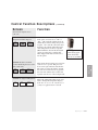
Carousel Plus W Series Dryer
Control Functions
Dryer functions are values that you can set or monitor. Press the Scroll button until
the function you want to set or monitor appears in the LED display.
✐
NOTE: Grey shaded screens denote optional functions. If the options were not purchased
with the dryer, those screens will not appear.
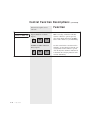
Control Function Flow Chart
The following flow chart provides a quick summary of the control functions. For
an explanation of each control function, see Control Function Descriptions. Screen
numbers correspond with numbers beside each block in the flow chart.
4
Operation
Operation l 4-3
✐
Display Menu
Number
NOTE: Screens 1-4 are
only displayed during
initialization.
5 1
When supplied for central
drying applications, these
control functions are not
available.
Control function only
available for MDC only.
✐
NOTE: Gray areas designate
parameters associated with
options.
4-4
l Operation
CNT DRY
Setpoint
Display
Actual
Display
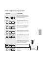
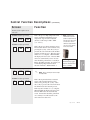
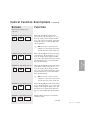
Control Function Descriptions
Screen
Function
SCREEN 1
Once power is turned on, this screen is
displayed for 5 seconds while the control
goes through self-checking.
Pr
up
SCREEN 2
CP
150
v2.0
d
v2.0
SCREEN 5 (Default Screen)
1
250
250
SCREEN 5 (Default Screen)
1
CNT
350
Indicates configuration as a central dryer.
DRY
SCREEN 6
2
This is the DEFAULT screen. It shows the
process air temperature setpoint and actual
temperature measured at the inlet to the
drying hopper. The (+) or (-) buttons can be
used to change the setpoint. Holding the
(+) or (-) buttons in will allow the number
to ramp up faster the longer the button is
held. The display will return to the default
screen from anyplace in the menu structure
if nothing is done after 10 minutes.
350
Shows the regeneration air setpoint and
actual temperature. The setpoint can not be
changed from this screen; it is shown only
as a reference.
When supplied for
central drying applications, this function
is not available.
Operation l 4-5
4
5.02
After the control versions is shown, the
screen flashes again for 1 second and displays the display board software version.
SCREEN 4
Operation
5.01
After the model number is displayed, this
screen flashes for 1 second and displays
the control board software version.
SCREEN 3
C
Once power is turned on and screen 1 is
displayed for 5 seconds, this screen is
displayed for another 3 seconds. It shows
the dryer model number for which the
control is configured.
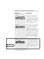
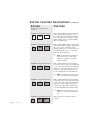
Control Function Descriptions
Screen
Function
SCREEN 7
This screen shows the actual return air
temperature measured at the inlet to the
process blower. If the optional aftercooler
flow control is installed, a setpoint will be
displayed on this screen as well. The (+) or
(-) buttons can be used to change the set
point. Holding the (+) or (-) buttons in
will allow the number to ramp up faster
the longer the button is held.
3
100
100
SCREEN 8
4
16
On
SCREEN 9 (MDC Option 150 &
200 only)
5
Control function only
available for MDC only.
4-6
l Operation
(continued)
10
-----
This screen is used to set the dryer to auto
start. The dryer must be on but not running to set auto start. The value shown is
the countdown time setpoint. It is
adjustable from 0.1 hours to 150 hours.
Once the countdown time is set, press the
“START” button. The display will show
ON to tell the operator that the auto start is
ON and counting. The auto start LED on
the display also flashes green when the
auto start is armed and counting down.
The LED will turn solid green when the
dryer starts. The dryer will begin operating when the control has finished counting
down.
This screen shows the amount of time the
conveying blower will run. Based on the
position of the demand sensor in the material receiver, this time may need adjusted.
The time should be set for the time it takes
to satisfy the demand sensor + 1 second.
If the MDC tries to load three consecutive
times without satisfying the demand signal
the dryer will display a passive alarm.
The range for this time setting is 5 to 20
seconds.
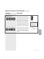
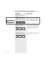
Control Function Descriptions
(continued)
Screen
Function
SCREEN 10 (Setback
Temperature Option)
If the dryer has the setback on temperature
option installed, this is the temperature
setpoint for the air at the outlet of the drying hopper. When this setpoint is reached,
the dryer will automatically change the
process setpoint to the setpoint shown on
Menu number 7, Screen 11. When the
temperature at the outlet of the hopper
drops below the setpoint (entered on this
screen, in this example 150) by the value
shown under C09, Screen 23, the dryer
will return to the normal drying setpoint.
6
150
120
SCREEN 11 (Setback Options)
7
145
250
✐
NOTE: See information on page 4-24 for
use of Setback.
Operation l 4-7
4
Operation
If the dryer has the setback on temperature
option installed, this is the temperature setpoint to which the process air will revert
once the air at the outlet of the hopper has
reached its setpoint (Screen 10, Menu
number 6).
When supplied for
central drying applications, these functions
are not available.
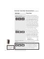
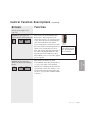
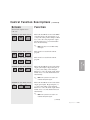
Control Function Descriptions
Screen
Function
SCREEN 13 (Dewpoint
Monitor/Dewpoint Control Option)
If the dryer has the dewpoint monitor
option installed, this screen will show the
actual dewpoint of the process delivery air
measured after the desiccant wheel in the
process position but before the process
heater. With the dewpoint monitor option
installed, there will only be an actual display (no setpoint value). Although the
dryer is capable of producing dewpoints
much lower than -40°F {-40°C}, the minimum sensor range is -40°F {-40°C}. dewpoint control will automatically adjust the
regeneration temperature to maintain dewpoint setpoint. Dewpoint control is not
active with -40°F {-40°C} setpoint.
8
-30
-40
SCREEN 14
0
0
Screens 15-27 require access
code 754.
SCREEN 15 (Set up Screen)
C
When supplied for
central drying applications, this function
is not available.
4-8
l Operation
(continued)
10
C01
This is the password entry screen that
gives the user access to the Set Up, Test
Mode, and Alarm History screens. The
user can get to the non-password protected
control functions through this screen by
pressing the scroll button and the adjust
setpoint button at the same time. This
works only if you are on menu #1 (default
screen). The access codes are as follows:
Set Up Screens
754
Test Mode Screens
755
Alarm History Screens
756
To exit the password section, enter 500 and
press scroll or cycle the power.
This is the process deviation temperature
screen. The range is 5 to 20°F {3 to
11°C}. This is the deviation temperature
band around the set point. If the dryer
goes outside this band, the dryer will
display a passive alarm (P1).
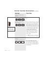
Control Function Descriptions
(continued)
Function
Screen
Screens 15-27 require access
code 754.
SCREEN 16 (Set up Screen)
C
375
C02
SCREEN 17 (Set up Screen)
C
off
C03
350
C04
SCREEN 19 (Set up Screen)
C
off
C05
When supplied for
central drying applications, this function
is not available.
This is a regeneration temperature screen.
✐
NOTE: There is normally no need to change
this temperature.
This is the regeneration heater autotune
screen. The autotune function can be
turned on by pressing the (+) key. Once
the (+) key is pressed, the screen will show
On and then start the autotune process.
This may take a minute or so to complete.
When finished the display will read "don".
The new PID values are automatically
saved. An autotune should be performed
on a cold dryer. It will autotune to the
value entered on Screen 18.
Operation l 4-9
4
C
This is the process heater autotune screen.
The autotune function can be turned on by
pressing the (+) key. Once the (+) key is
pressed, the screen will show On and then
start the autotune process. This may take a
minute or so to complete. When finished,
the display will read "don". The new PID
values are automatically saved. An autotune should be performed on a cold dryer.
Before beginning autotune, be certain your
normal drying temperature has been
entered on Screen 5, Menu number 1.
NOTE: Software may
allow the Process temperature setpoint limit up
to 450° F {232° C}, however Conair does not recommend a setpoint limit
over 375° F {191° C} due
to nuisance alarms.
Operation
SCREEN 18 (Set up Screen)
This is the process high temperature limit
screen. It limits how high the process
temperature setpoint can be adjusted.
(Screen 5) The range is 100 - 450°F
{38 - 232°C}.
✐
Control Function Descriptions
(continued)
Function
Screen
Screens 15-27 require access
code 754.
Control function only
available for MDC only.
SCREEN 20 (Set up Screen)
MDC Option (Models 150 & 200
only)
C
10
C06
SCREEN 21 (Set up Screen)
Regeneration Differential
Temperature
C
20
C07
SCREEN 22 (Set up Screen)
Regeneration Outlet temperature
C
4-10
l Operation
200
C08
This screen shows the time delay setting
for the conveying blower on the MDC.
This is the minimum time the MDC will
wait before starting another load cycle.
This screen shows the differential temperature at the regeneration inlet and the outlet
at the desiccant wheel. If the actual temperature is under the set value, the dryer
will alarm (P31), but will still run.
This screen is the actual temperature measured at the regeneration outlet on the
wheel.
Control Function Descriptions
(continued)
Function
Screen
Screens 15-27 require access
code 754.
SCREEN 23 (Set up Screen)
Setback Temperature Band Option
C
20
C09
off
C10
This screen is the Aftercooler Flow
Control Enable screen. By pressing the (+)
or (-) keys, the setting can be changed.
With this off or disabled, the dryer will not
open the flow control valve and try to control the return air temperature. There will
also be no set point value on Menu number
3, Screen 7.
Operation l 4-11
4
C
When supplied for
central drying applications, these functions
are not available.
Operation
SCREEN 24 (Set up Screen)
Aftercooler Flow Control Enable
Option
This screen is the Setback Temperature
Band screen. This temperature is the
amount the return air out of the hopper has
to drop below the activate setback temperature (Screen 10) before the original
process temperature is restored. For example, if the activate setback temperature was
180°F {82°C} and the dryer was in setback. The actual temperature measured at
the outlet to the hopper which has a 20°
Setpoint (Screen 23) would have to drop
below 160°F {71°C} to restore the original
process setpoint.
Control Function Descriptions
(continued)
Function
Screen
Screens 15-27 require access
code 754.
SCREEN 26 (Set up Screen)
C
off
C12
SCREEN 27 (Set up Screen)
Precooler Option
C
off
C13
When supplied for
central drying applications, these functions are not available.
Reserved function. This should always be
off.
This screen shows how the precooler is set
to operate. If it is set to "Off" the control
assumes the precooler is not installed in
the process line and will not control well
below 150°F {66°C}. If the screen is set to
"On" the control will assume the precooler
is connected in the process line and will
only allow setpoints from 100 to 150°F
{38 to 66°C}. The control will also
assume that the water flow rate is set
manually with a ball valve and make no
attempt to control water flow. The precooler option must be installed for this
screen to appear.
✐
NOTE: If this function is set to Off, make
sure the water to the precooler is turned off.
Screen 28-43 require access
code 755.
SCREEN 28 (Test Mode Screen)
H
4-12
l Operation
off
1
This is the Test Mode screen for the
process blower. By pressing the (+) or (-)
keys, the setting can be changed. When
set to "On", the process blower output will
be turned on for 3 seconds and then shut
off automatically.
Control Function Descriptions
(continued)
Function
Screen
Screen 28-43 require access
code 755.
SCREEN 29 (Test Mode Screen)
H
off
2
This is the Test Mode screen for the
process heater. By pressing the (+) or (-)
keys, the setting can be changed. When
set to "On", the process heater output will
be turned on for 3 seconds and then shut
off automatically.
✐
SCREEN 30 (Test Mode Screen)
H
off
3
off
4
This is the Test Mode screen for the regeneration heater. By pressing the (+) or (-)
keys, the setting can be changed. When
set to "On", the regeneration heater output
will be turned on for 3 seconds and then
shut off automatically.
✐
SCREEN 32 (Test Mode Screen)
H
off
5
SCREEN 33 (Test Mode Screen)
H
off
6
NOTE: The isolation contactor will not be
engaged so no electricity will go the heater.
The solid state relay contacts should close.
This is the Test Mode screen for the wheel
motor. By pressing the (+) or (-) keys, the
setting can be changed. When set to "On",
the wheel motor output will be turned on
for 3 seconds and then shut off automatically.
This Test Mode screen is not used in the
current program.
(continued)
Operation l 4-13
4
H
This is the Test Mode screen for the regeneration blower. By pressing the (+) or (-)
keys, the setting can be changed. When
set to "On", the regeneration blower output
will be turned on for 3 seconds and then
shut off automatically.
Operation
SCREEN 31 (Test Mode Screen)
NOTE: The isolation contactor will not be
engaged so no electricity will go the heater.
The solid state relay contacts should close.
Control Function Descriptions
Function
Screen
(continued)
Screen 28-43 require access
code 755.
SCREEN 34 (Test Mode Screen)
H
off
7
SCREEN 35 (Test Mode Screen)
H
off
8
This is the Test Mode screen for the isolation contactor. By pressing the (+) or (-)
keys, the setting can be changed. When
set to "On", the isolation contactor output
will be turned on for 3 seconds and then
shut off automatically.
This is the Test Mode screen for the alarm
output (horn and/or red light). By pressing
the (+) or (-) keys, the setting can be
changed. When set to "On", the alarm output will be turned on for 3 seconds and
then shut off automatically.
✐
SCREEN 36 (Test Mode Screen)
H
off
9
This is the Test Mode screen for the precooler flow control valve. By pressing the
(+) or (-) keys the setting can be changed.
When set to "On" the precooler flow control valve output will be turned on for 3
seconds and then shut off automatically.
✐
SCREEN 37 (Test Mode Screen)
H
off
10
H
4-14
l Operation
off
11
NOTE: If the optional precooler flow control
valve is not installed nothing will happen.
This is the Test Mode screen for the aftercooler flow control valve. By pressing the
(+) or (-) keys, the setting can be changed.
When set to "On", the aftercooler flow
control valve output will be turned on for
3 seconds and then shut off automatically.
✐
SCREEN 38 (Test Mode Screen)
NOTE: The alarm light on the membrane
switch will not come on. If the optional
alarm horn or red light is not installed
nothing will happen.
NOTE: If the optional aftercooler flow control valve is not installed nothing will happen.
This screen is not used in the current
program.
Control Function Descriptions
(continued)
Function
Screen
Screen 28-43 require access
code 755.
SCREEN 39 (Test Mode Screen)
H
off
12
This is the Test Mode screen for the MDC
conveying blower. By pressing the (+) or
(-) keys, the setting can be changed. When
set to "On", the conveying blower output
will be turned on for 3 seconds and then
shut off automatically.
✐
SCREEN 40 (Test Mode Screen)
H
off
13
SCREEN 41 (Test Mode Screen)
off
14
H
off
15
This screen is not used in the current
program.
This is the Test Mode screen for the alarm
output (yellow light). By pressing the (+)
or (-) keys, the setting can be changed.
When set to "On", the alarm output will be
turned on for 3 seconds and then shut off
automatically.
✐
SCREEN 43 (Test Mode Screen)
H
off
16
NOTE: If the optional tricolor light is not
installed nothing will happen.
This is the Test Mode screen for the alarm
output (green light). By pressing the (+)
or (-) keys, the setting can be changed.
When set to "On", the alarm output will be
turned on for 3 seconds and then shut off
automatically.
✐
NOTE: If the optional tricolor light is not
installed nothing will happen.
(continued)
Operation l 4-15
4
SCREEN 42 (Test Mode Screen)
This screen is not used in the current
program.
Operation
H
NOTE: If the dryer is not an MDC nothing
will happen.
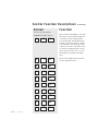
Control Function Descriptions
(continued)
Function
Screen
Access code 756 required.
SCREEN 44 (Alarm Screen)
4-16
l Operation
A
1
P3
A
2
A1
A
3
A5
A
4
A4
A
5
P1
A
6
P5
A
7
A7
A
8
A2
A
9
A6
A
10
P2
This is the first Alarm History screen. In
this section, the last 10 alarms that have
occurred are saved, starting with the
most recent alarm. The number in the
setpoint screen shows the list of alarms
1-10. The alarm code shows up in the
actual screen. Some of the alarm codes
are shown on the display label. Please
refer to the Troubleshooting section of
this manual for all alarm code definitions.
These are the additional alarm screens.
See the explanation above.
Control Function Descriptions
(continued)
Function
Screen
Screen 45-49 require access
code 754.
SCREEN 45 (Setback
Temperature Enable Option)
C
off
C11
off
C14
SCREEN 47 (Degree F/Degree C)
C
F
C15
This screen shows how the precooler flow
control is set to operate. The precooler
flow control option must be installed for
this screen to appear. It will also assume
the water flow solenoid valve is piped in
the water line and the dryer control will
regulate water flow to control temperature.
This is the temperature units screen. It is
used to change the temperature display
from °F to °C or °C to °F. Use the (+) or
(-) keys to toggle between °C and °F.
Operation l 4-17
4
H
When supplied for
central drying applications, these functions are not available.
Operation
SCREEN 46 (Precooler Flow
Control Enable Option) (not available at this time)
This screen shows the setting of the setback option. It can be set to “Off” or
“On”. “Off” turns the setback mode off,
and the dryer will not change the process
setpoint. “On” tells the control the dryer
should go into setback when the hopper
outlet temperature reaches its setpoint
(Menu number 6, Screen 10). If setback
option was ordered, it is turned “Off”
when shipped and must be turned on to
use the option.
Control Function Descriptions
Screen 45-49 require access
code 754.
Control function only
available for MDC only.
SCREEN 48 (MDC Conveying
Option Shutdown on Alarm
Option)
C
off
C16
SCREEN 49 (MDC Shutdown
Delay Option)
H
4-18
l Operation
off
C17
(continued)
Function
This screen can be used to determine if the
MDC conveying on function will shutdown or continue to operate upon any
dryer alarm. When turned off, the MDC
blower will continue to cycle indefinitely.
Use this screen in the event Screen 48 is
enabled to set the amount of time the conveying function will continue to operate
once the dryer has alarmed. If Screen 48
is disabled, the conveying functions will
continue indefinitely.
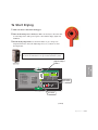
To S t a r t D r y i n g
1 Make sure there is material in the hopper.
2 Turn on the main power to the dryer. Make sure the dryer’s disconnect dial
is in the ON position. This powers up the control and the display lights will
illuminate.
3 Set the drying temperature. Use the Scroll button to get to the process
temperature function. Press the Adjust Setpoint (+) or (-) buttons to select
the temperature.
When configured as a central dryer, the drying temperature
can not be set since there is no process heater in the system.
Setpoint Adjust
Buttons
1
2
3
4
5
6
7
8
Process Temp.
Regen. Temp.
Return Air Temp.
Auto Start
Load Time (MDC)
Activate Setback Temp.
Setback Temp.(Process)
Dewpoint
Process Blower
Regen. Blower
Auto Start
Process Heater
Regen. Heater
Dewpoint Control
Conveying Blower
Set-Back Temp.
Acknowledge
Alarm Button
Scroll Button
(continued)
Operation l 4-19
4
Passive Alarms
P1
Process Temp Deviation
P3
Regen Temp Deviation
P5
Return Air Mid High Temp
P17 MDC Conveying Demand
Operation
Shutdown Alarms
A1
Process High Temp
A2
Process Loop Break
A3
Process Heater High Temp
A4
Regen Heater High Temp
A7
Return Air High Temp
A49 Process Protection High Temp
A53 Process Blower Overload
A55 Wheel Rotation Failure
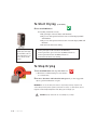
To S t a r t D r y i n g
(continued)
Start
4 Press the START button.
If everything is installed correctly:
• The green light on the start button will illuminate.
• The process and regeneration blowers turn on and the display LEDS
will illuminate.
• The process and regeneration heaters turn on and the display LEDs will
illuminate.
• The desiccant wheel starts turning.
When configured as a
central dryer, the high
setpoint limits can not
be set since there is no
process heater in the
system.
• The green light on the start button will illuminate.
• The regeneration, process blowers and LEDs will turn on.
• The regeneration heater and LEDs will turn on.
• The desiccant wheel starts turning.
To S t o p D r y i n g
1 Press the STOP button. The Stop LED blinks red.
• The blowers continue running for a few minutes
Stop
to cool the heaters.
2 Be sure to disconnect and lockout the main power if you have stopped the
dryer to perform maintenance or repair.
IMPORTANT: Do not use the main power switch to stop the dryer. Turning off power to the
control and dryer during normal operation prevents the necessary cool-down period, and can
trigger the shut down/high temperature alarm during your next drying cycle.
CAUTION: Improper shut down can cause damage to your dryer.
4-20
l Operation
Using the Auto Start Countdown
Function
The countdown function allows the user to set the W Wheel dryer to automatically start at a predetermined time. The countdown time can be set from 0.1 to
150.0 hours.
To set the countdown time:
1 Use the Scroll button to access the function (Menu 4, Screen 8).
4
16
ON
Auto Start
2 Use the Setpoint Adjust keys to set the desired countdown time, in hours.
3 Press the Start button. The Auto Start LED will blink to indicate that Auto Start
is armed.
To disable auto start once armed cycle the power off and on.
Operation l 4-21
4
Operation
How to Disable the Auto Start on
the DC-1 Control
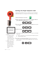
Setting the High Setpoint Limit
Using the high setpoint limit can protect your drying process from accidental or
unauthorized settings above an acceptable level for the material you are drying.
Start
1 Turn on the main power to the dryer.
2 While at the default screen (Screen 5) press the scroll button and the setpoint (-) minus button simultaneously to get to Screen 14.
0
0
3 On screen 14 enter the password for set up screens (754) using the setpoint
(+) or (-) button.
When configured as a
central dryer, the high
setpoint limits can not
be set since there is no
process heater in the
system.
✐
0
754
0
C
385
C02
4 Scroll to screen 16.
This is your current high setpoint limit. Press (+) or (-) keys to set a new high
setpoint limit.
NOTE: Conair is not responsible for damage caused by
excessively high drying
✒
Tip: We recommend that you set your high setpoint limit 10° higher than your maximum high temperature setpoint.
setpoints that are not in
accordance with your drying
✐
material recommendations.
NOTE: Software may allow
the Process temperature
setpoint limit up to 450° F
{232° C}, however Conair
does not recommend a setpoint limit over 375° F
{191° C} due to nuisance
alarms.
4-22
l Operation
5 To lock in your new high setpoint limit and exit the password protected
screens, scroll back to screen 14, then enter 500 and press scroll or cycle the
power off and on.
0
754
0
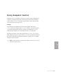
Using Dewpoint Control
Dewpoint control is a feature that can help you to reduce energy consumption. It
does this by varying the temperature of the regeneration air from its default setpoint of 350° F {177° C}, to maintain a setpoint that you have entered on the
process dewpoint screen (Screen 11).
Example:
If your material is not difficult to dry, it may dry adequately with -20° F
{-29° C} dewpoint air. When -20° F {-29° C} is entered as the setpoint (Screen
11), the dryer will gradually lower the regeneration air temperature to a point
where the dryer’s delivery air is controlled at -20° F {-29° C} dewpoint.
The dewpoint control is active with setpoint values of -39° F {-39.4° C} and
higher. When the setpoint is -40° F {-40° C} or lower, the regeneration temperature will be maintained at the default temperature of 350° F {177° C} and the
dewpoint control is inactive.
✐
NOTE: For more information concerning specific dewpoint control screens, see Control
Function Descriptions, page 4-5.
4
Operation
Operation l 4-23
U s i n g t h e S e t b a c k Fe a t u r e
(Optional)
The setback function available on the Carousel Plus W series dryer with DC-1
control is designed to save you money on energy costs and keep you from over
drying your material.
When supplied for central drying applications,
the W series dryer is not
equipped with a process
heater. Therefore the setback function is not
applicable.
The optional setback feature, if installed from the factory, is disabled and will need
to be enabled in access code 754 (Screen 45).
This is how setback operates when installed and turned on:
The control monitors the temperature of the air exiting the drying hopper. If that
temperature reaches a customer entered setpoint (Screen 10), the delivery process
air temperature will automatically setback to a customer-entered setpoint
(Screen 11). Then, if the air exiting the drying hopper drops below the customerentered temperature on Screen 10 by an amount greater than what is shown on
Screen 23, the process temperature will automatically reset back to the original
process temperature (Screen 5).
To turn on and setup the setback option:
1 Enter the access code 754 (see Screen 14). Then using the scroll buttons,
scroll to menu Screen 45.
2 Turn the setback function for temperature option to "On" by pressing the
(+) key.
✐
3 Push the scroll button to return to access code 754, then change the code to
NOTE: Screen 5 will
500. Once the number has been entered push the scroll button or cycle the
power to clear the access code.
still show normal drying temperature as
setpoint when setback
4 Go to Screen 10. This is where you will set the temperature setpoint for the air
at the outlet of the drying hopper.
is active.
5 On Screen 11 set the temperature setpoint to which the process air will revert
to once the air at the outlet of the drying hopper has reached its setpoint.
(continued)
4-24
l Operation
U s i n g t h e S e t b a c k Fe a t u r e
(Optional)
(continued)
6 Use the setback temperature band screen (Screen 23) to set the amount the
return air temperature has to drop below the setpoint on Screen 10 before
the original process temperature is restored. For example, if the activate setback
temperature was 180ºF {82ºC} and the value on Screen 23 is set to 20, once the
dryer moves into setback, the actual temperature measured at the outlet of the
hopper would have to drop below 160ºF {71ºC} to restore the original process
set point.
7 When the “Setback” Feature is active, the Setback LED will be lit, and the
actual temperature on screen 5 will eventually approach the setpoint entered in
screen 11.
S e t b a c k Fe a t u r e G u i d e l i n e s
(Optional)
Setback Return Temp
Setback Temp
Screen #10
(Process) Screen #11
160° F {71° C}
120° F {49° C}
150° F {66° C}
240° F {116° C}
135° F {57° C}
180° F {82° C}
300° F {149° C}
160° F {71° C}
200° F {93° C}
340° F {171° C}
180° F {82° C}
220° F {104° C}
To turn off the setback option:
1 Enter the access code 754 (see Screen 14). Then using the scroll buttons,
scroll to menu Screen 45.
2 Turn the setback function for temperature option to "Off" by pressing the
(-) key.
3 Push the scroll button to return to access code 754, then change the code to
500. Once the number has been entered push the scroll button or cycle the
power to clear the access code.
Operation l 4-25
4
Normal
Drying Temp
Operation
Careful selection of setpoint values in these functions is necessary for the setback
to operate properly. The following table is only a guideline of recommended
settings for these setpoints. It will be necessary for each customer to determine the
best setpoints for their application based on experience.
S e t b a c k Fe a t u r e G u i d e l i n e s
(Optional)
(continued)
A recommended way to determine the “Setback Return Temperature” setpoint is to
monitor the actual temperature of this function during pre-drying of your material
at start-up, and while running at your normal maximum material throughput. The
“Setback Return Temperature” setpoint should be set 10 to 20° above maximum
temperature noted in these situations.
The “Setback Temperature (Process)” setpoint you select should be adequate to
reduce the temperature significantly enough to prevent over-drying of your material. However, keep in mind that the cooler the temperature selected, the longer it
will take for the material to heat back up to its proper drying temperature once the
dryer comes out of Setback mode.
When drying at low temperatures (for example 160 - 180° F {71 - 82° C}), you are
able to setback the temperature only a small amount. The “Setback Temperature
(Process)” should not be set lower than 150° F {66° C}, even if the control will
allow it. It is very likely the dryer will not be able to achieve low temperatures
without adding additional cooling to the process air circuit. The maximum achievable setpoint is dependent on the temperature of the return air coming back to the
dryer. As the return air temperature climbs, the temperature that the dryer is capable of controlling at climbs. For example, if the return air to the dryer is 110° F
{43° C}, the dryer may not be able to control at a “Setback Temperature
(Process)” setpoint below 150 - 155° F {66 - 68°C}.
✐
NOTE: Selecting too low of a setpoint for Screen 26 may result in nuisance A2 Process
Loop Break alarms if the dryer is not able to achieve this setpoint.
4-26
l Operation
SECTION
5
Maintenance
Preventative maintenance checklist . . . . . . . 5-2
Checking the dewpoint . . . . . . . . . . . . . . . . 5-3
Cleaning the hopper. . . . . . . . . . . . . . . . . . 5-5
Cleaning the process filter . . . . . . . . . . . . . 5-6
Cleaning the regeneration filter . . . . . . . . . . 5-8
Cleaning the aftercooler coils . . . . . . . . . . 5-10
Cleaning the precooler coils . . . . . . . . . . . 5-12
Inspecting hoses and gaskets . . . . . . . . . . 5-12
Maintenance l 5-1
5
Maintenance
Cleaning the volatile trap on the demister . . 5-12
Preventative Maintenance
Checklist
Routine maintenance will ensure optimum operation and performance of the
W Series Dryer. We recommend the following maintenance schedule and tasks.
• Whenever you change materials
❒ Drain and clean the hopper.
• We e k l y, o r a s o f t e n a s n e e d e d
❒ Clean or replace the process and regeneration filters.
You may need to clean filters more often than weekly. Frequency depends
on how much material you process and how dusty or full of fines it is.
❒ Inspect hoses and hose connections.
Check for damage, kinks, or loose hose clamps. Replace any hoses that
show signs of damage or wear. Reposition and tighten loose hose clamps.
• Monthly
❒ Clean the optional aftercooler and precooler coils.
You may need to clean the coils more often than monthly. Frequency will
depend on the type and volume of material you process.
• Every six months
❒ Inspect gaskets for damage or wear.
Damaged gaskets can allow moisture to seep into the closed-loop drying
system. Replace any gasket that is torn or cracked.
❒ Verify dewpoint readout and performance with calibrated portable
instrument.
❒ Measure current draw on all 3 legs of heater wires. This is to ensure
the heater is working properly.
5-2 l Maintenance
Checking the Dewpoint
It is a good idea to monitor the dewpoint performance of your dryer periodically
with a calibrated portable dewpoint monitor, to ensure it is performing at maximum capacity. Even if your dryer has a dewpoint readout, comparing it to a
portable instrument periodically will confirm that the dewpoint sensor and readout
is performing properly.
✐
NOTE: Portable dewpoint monitors purchased from Conair are
provided with a male connector
that plugs into the dewpoint
To check dewpoint:
Check port. If you purchased
your portable instrument else-
1 Connect your portable dewpoint meter to the
where, the male connector is
dewpoint check port of the dryer.
2 Turn on the portable instrument, and ensure
there is positive airflow through the sensor.
available through the Conair
✐
parts department.
NOTE: The dewpoint check port
was not included on early dry-
3 Monitor the readout and allow ample time for it to stabilize before
disconnecting it. Some dewpoint monitors require a substantial amount of
time for residual moisture to be purged from the sensor.
ers. It can be added easily.
Contact the Conair parts department or follow the alternate
procedure.
4 In the event the dewpoint in not satisfactory, refer to the Troubleshooting
section of the manual, alarm P9.
Alternate Procedure: (for dryers with no dewpoint check port)
3 At the bottom end (cool air inlet) of the process heater tube, remove
1/8 inch NPT pipe plug and connect your portable dewpoint monitor at
this location. If there are existing connections for the dryer’s dewpoint sensor,
locate a 2nd 1/8 inch NPT port, or connect your dewpoint sensor in series with
the dryer sensor. Do not install a tee to split the air between the dryer’s sensor
and your portable instrument. This may cause one of them to be starved for
adequate sample air.
4 Turn on the dryer.
Maintenance l 5-3
5
2 Open the right side panel of the dryer, and locate the process heater tube.
Contact Conair Parts
(800) 458 1960
From outside of the
United States, call:
(814) 437 6861
Maintenance
1 Stop dryer and allow it to cool.
Replacement dewpoint monitors, male connectors and
dewpoint check ports are
available from Conair.
Checking the Dewpoint
(continued)
5 Turn on the portable instrument, and ensure there is positive airflow through
the sensor.
6 Monitor the readout and allow ample time for it to stabilize before disconnecting the portable instrument. Some dewpoint monitors require a substantial amount of time for residual moisture to be purged from the sensor.
7 In the event the dewpoint is not satisfactory, refer to the Troubleshooting
section of the manual, alarm P9.
8 Stop the dryer, and allow it to cool down. Then disconnect your portable
instrument and replace any pipe plugs that may have been removed.
9 Close side panels and start the dryer.
5-4 l Maintenance
Cleaning the Hopper
CAUTION: Hot surfaces. Always protect yourself from hot surfaces inside and outside the dryer and drying hopper.
The hopper, spreader cone, and discharge assembly should be cleaned thoroughly
between material changes to prevent resin contamination.
1 Drain the hopper. Place a container
beneath the hopper’s drain port
to catch the material.
2 Remove the spreader cone. Open the
3 Clean the spreader cone and the inside of the hopper. Make sure you also
clean the return air screen at the return air outlet of the hopper.
4 Repeat the steps in reverse order to reassemble the hopper before adding
material.
Maintenance l 5-5
5
Maintenance
hopper door. Reach into the hopper.
Grasp the spreader cone tube, lift up
slightly, twist and then push down to
release it. Tilt the cone assembly and
pull it out through the hopper door.
Cleaning the Process Filter
Clogged filters reduce air flow and dryer efficiency. Cleaning frequency depends
on how much material you process and how dusty or full of fines it is.
1 Push in on the sides to release
the tabs on the front cover.
Remove the cover.
CAUTION: Hot surfaces.
Always protect yourself
from hot surfaces inside
and outside the dryer
and drying hopper.
2 Remove the cover wing nut,
then pull the cap off.
3 Remove the filter wing nut,
then remove the filter.
5-6 l Maintenance
Cleaning the Process Filter
(continued)
4 Remove outer filter and clean it with soapy water.
Let air dry.
5 Clean the filter by laying it on its side and
gently tapping it on the floor. Replace
damaged, worn, or clogged filters.
CAUTION: Wear eye protection. If you use
compressed air to clean the equipment, you
must wear eye protection and observe all
OSHA and other safety regulations pertaining to
the use of compressed air.
place and in good condition.
✒
TIP: If gasket on the process filter cap becomes loose or detached from the filter cap, resecure with high temperature silicone adhesive.
Maintenance l 5-7
5
Maintenance
6 Reverse the procedure to reinstall the process filter. Ensure that the gasket on filter cap is in
Cleaning the Regeneration Filter
Clogged filters reduce air flow and dryer efficiency. Cleaning frequency depends
on how much material you process and how dusty or full of fines it is.
1 Push in on the sides to release
the tabs on the front cover.
Remove the cover.
CAUTION: Hot surfaces.
Always protect yourself
from hot surfaces inside
and outside the dryer
and drying hopper.
2 Remove outer filter and clean it
with soapy water. Let the outer
filter air dry.
3 Loosen the hose clamp holding
the regeneration filter onto the
regeneration inlet and remove
the filter.
5-8 l Maintenance
Cleaning the Regeneration Filter
(continued)
4 Clean dust, fines, and dirt from the filter,
or replace it with a new filter. Clean the
filter by laying it on its side and gently
tapping it on the floor. Replace damaged,
worn, or clogged filters.
CAUTION: Wear eye protection. If you use
compressed air to clean the equipment, you
must wear eye protection and observe all
OSHA and other safety regulations pertaining to
the use of compressed air.
5 Reverse the procedure to reinstall the regeneration filter.
5
Maintenance
Maintenance l 5-9
Cleaning the Aftercooler Coils
The aftercooler coils will need to be kept clean to keep the aftercooler working
efficiently. Cleaning frequency depends on the type and amount of material you
process.
1 Stop the dryer and lockout the main power.
2 Turn off the water flow to the water supply line. Disconnect supply and
return lines.
✐
NOTE: If an optional flow control was added with the aftercooler, remove the compression fitting from the aftercooler inlet. Loosen the fitting on the flow control, then swing
the copper water supply tube out and away from the aftercooler inlet.
3 Remove the screws securing the aftercooler in the aftercooler housing.
✒ TIP: If the aftercooler (without a flow control) was installed using the recommended
24 inch {61 cm} of flexible hoses, there is no need to disconnect the hoses from the
aftercooler inlet and outlet.
4 Remove the aftercooler assembly from the aftercooler housing.
(continued)
5-10 l Maintenance
Cleaning the Aftercooler Coils
5 Clean the assembly using a mild soap and water. Let the assembly
dry thoroughly before installation. In severe situations, steam cleaning
or use of solvents maybe necessary.
CAUTION: During the cleaning process, DO NOT cut or remove the
stainless steel wire that holds the assembly together.
6 Inspect the condition of the gasket. If it is damaged, replace the
gasket.
7 Reassemble by repeating the steps in reverse order.
8 Connect the water supply line to the inlet. If a manual shut off
valve is used, it should be mounted on the inlet line as well.
9 Connect the outlet of the aftercooler to the inlet of the flow control
valve using the pre-shaped copper tubing and compression fittings
provided.
5
Maintenance
Maintenance l 5-11
Cleaning the Precooler Coils
If you have the optional precooler, you need to clean the cooling coils to keep
them working efficiently. See Appendix C for details.
C l e a n i n g t h e Vo l a t i l e Tr a p o n
the Demister
If you have the optional volatile trap, you need to clean the trap to keep it working
efficiently. See Appendix D for details.
Inspecting Hoses and Gaskets
Loose or damaged hoses and gaskets can allow moisture to seep into the closedloop drying system.
1 Follow the hose routing of all the hoses within the dryer and inspect all
hoses, clamps, fittings, and gaskets.
2 Tighten any loose hose clamps or fittings.
3 Replace worn or damaged hoses and gaskets.
5-12 l Maintenance
SECTION
6
Tr o u b l e s h o o t i n g
Before beginning . . . . . . . . . . . . . . . . . . . . 6-2
A few words of caution . . . . . . . . . . . . . . . 6-3
DIAGNOSTICS
How to identify the cause of a problem . . . . 6-4
Alarms. . . . . . . . . . . . . . . . . . . . . . . . . . . 6-5
Dewpoint troubleshooting . . . . . . . . . . . . . 6-24
Po o r m a t e r i a l d r y i n g t r o u b l e s h o o t i n g . . . . . 6 - 2 5
R E PA I R
Replacing fuses . . . . . . . . . . . . . . . . . . . . 6-30
Checking heater solid state relays . . . . . . . 6-31
Replacing the heaters
Regeneration heater tube . . . . . . . . . . 6-33
Process heater tube . . . . . . . . . . . . . . 6-35
Replacing the desiccant wheel . . . . . . . . . . 6-37
Replacing the desiccant wheel motor . . . . . 6-38
Tr o u b l e s h o o t i n g l 6 - 1
6
Troubleshooting
Checking or replacing temperature sensors . 6-32
✐
Before Beginning
NOTE: Use of test
mode screens 28-43
may assist with the
You can avoid most problems by following the recommended installation and
maintenance procedures outlined in this User Guide. If you do have a problem,
this section will help you determine what caused it and how to fix it.
determining of possible cause of an alarm.
Access code 756.
Before you open the side panels of the dryer be sure to:
❏ Diagnose causes from the control panel.
1
Press
once to silence the optional audible alarm and display the
alarm message.
2
Address the alarm message and fix the problem. (Refer to the alarm
descriptions later in this section.)
3
Press
again to clear the alarm. If the alarm reappears the problem
was not fixed.
❏ Diagnose causes from the front of the dryer.
You can locate any problem from the front of the dryer.
Shutdown Alarms
A1
Process High Temp
A2
Process Loop Break
A3
Process Heater High Temp
A4
Regen Heater High Temp
A7
Return Air High Temp
A49 Process Protection High Temp
A53 Process Blower Overload
A55 Wheel Rotation Failure
Passive Alarms
P1
Process Temp Deviation
P3
Regen Temp Deviation
P5
Return Air Mid High Temp
P17 MDC Conveying Demand
6 - 2 l Tr o u b l e s h o o t i n g
1
2
3
4
5
6
7
8
Process Temp.
Regen. Temp.
Return Air Temp.
Auto Start
Load Time (MDC)
Activate Setback Temp.
Setback Temp.(Process)
Dewpoint
Process Blower
Regen. Blower
Auto Start
Process Heater
Regen. Heater
Dewpoint Control
Conveying Blower
Set-Back Temp.
Acknowledge
Alarm Button
Before Beginning
(continued)
❏ Find the wiring and equipment diagrams that were shipped
with your dryer. These diagrams are the best reference for correcting a problem. The diagrams also will note any custom features,
such as special wiring or alarm capabilities, not covered in this
User Guide.
See warnings
below. Open the
electrical enclosure
to check fuses and
heater contactors.
A Fe w Wo r d s o f C a u t i o n
The Carousel Plus W Series Dryer is equipped with numerous safety devices.
Do not remove or disable them. Improper corrective action can lead to hazardous conditions and should never be attempted to sustain production.
WARNING: Only qualified service personnel should examine and correct
problems that require opening the dryer’s electrical enclosure or using
electrical wires to diagnose the cause.
WARNING: High voltage. Always stop the Carousel Plus W series dryer,
disconnect and lock out the main power source before troubleshooting
or performing repairs.
Tr o u b l e s h o o t i n g l 6 - 3
6
Troubleshooting
CAUTION: Hot surfaces. Always protect yourself from hot surfaces inside
and outside of the dryer and hopper.
✐
How to Identify the Cause of a
Problem
NOTE: Pushing the
Acknowledge Alarm button
when there is no active alarm
will display the most recent
alarm code.
✐
Dryer alarms are indicated by an illuminated Acknowledge Alarm light on the W
Series Dryer control panel. Shutdown alarms will energize optional audible and
visual alarm indicators.
A problem can trigger two types of alarms:
• Shutdown: The dryer has automatically shut down because it detected a
NOTE: The dryer cannot be
started if a passive alarm is
present on power-up.
serious problem that could damage your material or dryer.
• Passive: The dryer continues to operate, but warns of a problem that could
prevent correct drying of your material. If ignored, this problem could lead to a
condition that will shut down the dryer.
Shutdown Alarms
A1
Process High Temp
A2
Process Loop Break
A3
Process Heater High Temp
A4
Regen Heater High Temp
A7
Return Air High Temp
A49 Process Protection High Temp
A53 Process Blower Overload
A55 Wheel Rotation Failure
Passive Alarms
P1
Process Temp Deviation
P3
Regen Temp Deviation
P5
Return Air Mid High Temp
P17 MDC Conveying Demand
1
2
3
4
5
6
7
8
Process Temp.
Regen. Temp.
Return Air Temp.
Auto Start
Load Time (MDC)
Activate Setback Temp.
Setback Temp.(Process)
Dewpoint
Process Blower
Regen. Blower
Auto Start
Process Heater
Regen. Heater
Dewpoint Control
Conveying Blower
Set-Back Temp.
When the alarm light is displayed:
Acknowledge
Alarm LED and
Button
1 Press the Acknowledge Alarm button once to silence the
optional audible alarm and display the alarm message. Pressing the
Acknowledge Alarm button once also changes the alarm LED from blinking to
solid.
2 Find the error message in the diagnostics table of this Troubleshooting
section. Use information provided to diagnose and resolve the cause of the
alarm.
3 Note that, after correcting the problem, pressing the Acknowledge Alarm
button a second time will clear the alarm. If the alarm reappears,
the cause has not been resolved.
✐
NOTE: When the dryer detects abnormally high temperature in the process heater, the
6 - 4 l Tr o u b l e s h o o t i n g
dryer immediately shuts down and an error message appears in the display window.
Alarms
A problem can trigger two types of alarms:
• Shutdown (A#): If the red Acknowledge Alarm LED is blinking, the alarm is a
When supplied for central
drying applications, these
shutdown alarms are not
available.
shutdown alarm. The dryer has automatically shut down because it has detected a
serious problem that could damage your material or dryer. Note that once the
Acknowledge Alarm button is pressed once, the blinking red LED becomes solid.
• Passive (P#): If the amber Acknowledge Alarm LED is blinking, the alarm is a
passive alarm. The dryer continues to operate, but warns of a problem that could
prevent correct drying of your material. If ignored, this problem could lead to a
condition that will shut down the dryer. Note that once the Acknowledge Alarm
button is pressed once, the blinking amber LED becomes solid.
Problem
Possible cause
Solution
A1 - Process High
Temperature – If the process
temperature exceeds the
process high temperature setpoint, it shuts down the dryer.
Defaults are set to 385°F
{196°C} for 20 seconds.
The process high temperature setpoint is
not at least 10°F {6°C} above the drying
setpoint.
Reset the process high temperature setpoint at least 10°F {6°C} above the drying setpoint.
One of the process solid state relays has
failed.
Replace the solid state relay.
The air lines are restricted or loose.
Straighten any crimps in the hoses.
Tighten any loose hoses.
The process setpoint is too low.
Set the process setpoint higher or install
an optional precooler.
The process heater output on the control
board has failed.
Replace the control board.
6
Troubleshooting
Tr o u b l e s h o o t i n g l 6 - 5
Alarms
• Shutdown (A#): The dryer has automatically shut down because it has detected a serious problem that could damage your material or dryer.
• Passive (P#): The dryer continues to operate, but warns of a problem that could
prevent correct drying of your material. If ignored, this problem could lead to a
condition that will shut down the dryer.
When supplied for central drying applications, these shutdown alarms are not available.
Problem
Possible cause
Solution
A2 - Process Temperature
Loop Break – If the process
temperature is outside of the
operator entered deviation,
alarm band (see Process High
Temperature Deviation passive
alarm) and the process temperature is not moving
towards the setpoint at a rate
greater than specified, it shuts
down the dryer. Defaults are
set at 3°F {2°C} over 20
seconds.
Process RTD is loose or has fallen out.
Check the process RTD and tighten if
needed.
The process heater has failed.
Check the heater fuses, and resistance
across each leg of the process heater.
The air lines are restricted or loose.
Straighten any crimps in the hoses.
Tighten any loose hoses.
The process blower is not running or is
running in the wrong direction.
Correct the cause of the non-running
blower or reverse the rotation of the
blower.
The process heater output on the board
has failed or the output fuse has failed.
Replace the board or the fuse for the
output.
Process setpoint is set too low.
Adjust to higher setting or add a
precooler.
Setback setpoint is set too low.
Adjust to higher setting or add a
precooler.
There is an air flow blockage or loose
hoses.
Locate and remove any airflow
restrictions.
A3 - Process Heater High
Temperature – The snap
switch in the process heater
tube opens due to excessive
temperature.
Tighten any loose hoses.
The process blower is not running or
running in the wrong direction.
Correct the cause of the non-running
blower (blown fuse, etc.) or reverse the
rotation of the blower. See Installation
section entitled, Checking for proper air
flow.
(continued)
6 - 6 l Tr o u b l e s h o o t i n g
Alarms
• Shutdown (A#): The dryer has automatically shut down because it has detected a serious problem that could damage your material or dryer.
• Passive (P#): The dryer continues to operate, but warns of a problem that could
prevent correct drying of your material. If ignored, this problem could lead to a
condition that will shut down the dryer.
When supplied for central drying applications, these shutdown alarms are not available.
Problem
Possible cause
Solution
A3 - Process Heater High
Temperature (cont.)– The
snap switch in the process
heater tube opens due to excessive temperature.
The isolation contactor failed in the
closed position.
Replace the isolation contactor.
The process heater output on the board
has failed.
Replace the board.
The heater solid state relays (SSRs) failed. Replace the failed heater solid state
relays (SSRs).
A4 - Regeneration Heater
High Temperature – The
snap switch in the regeneration
heater tube activated due to
excessive temperature.
The regeneration exhaust is blocked or the Locate and remove any airflow restricair hoses are loose.
tions.
Tighten hoses.
The regeneration blower is not running or
running in the wrong direction.
Correct the cause of the non-running
blower (blown fuses, etc.) or reverse
the rotation of the blower.
The isolation contactor failed in the
closed position.
Replace the isolation contactor.
Replace the board.
The hopper does not contain enough
material.
Make sure your material supply system
is working properly.
You are drying at a high drying tempera- Ensure water flow to the aftercooler.
ture (above 240°F {116°C}) or you are
running at low throughputs.
(continued)
Tr o u b l e s h o o t i n g l 6 - 7
6
A7 - Return Air High
Temperature – If the return
air temperature at the inlet to
the blower is greater than
180°F {82°C}, it shuts down
the dryer.
The regeneration heater output on the
board has failed.
Troubleshooting
The heater solid state relays (SSRs) failed. Replace the failed heater solid state
relays (SSRs).
Alarms
• Shutdown (A#): The dryer has automatically shut down because it has detected a serious problem that could damage your material or dryer.
• Passive (P#): The dryer continues to operate, but warns of a problem that could
prevent correct drying of your material. If ignored, this problem could lead to a
condition that will shut down the dryer.
When supplied for central drying applications, these shutdown alarms are not available.
Problem
Possible cause
Solution
A7 - Return Air High
Temperature (cont.) – If the
return air temperature at the
inlet to the blower is greater
than 180°F {82°C}, it shuts
down the dryer.
The aftercooler does not have enough
water.
Turn on the water supply, or fix any
leaks or blockages.
The aftercooler coils are dirty.
Clean the aftercooler coils. See
Maintenance section entitled, Cleaning
the aftercooler coils.
A10 & P26 - Process RTD
Integrity – If the process
RTD is faulty, it shuts down
the dryer.
The process RTD connection to the
control box is loose.
Check the connection to the receptacle
and tighten if needed.
The connection in the electrical enclosure for the process RTD is loose.
Check the RTD plug connection and
tighten if needed.
The connection of the RTD plug on the
control board is loose.
Check the plug connection and tighten
if needed.
The process RTD has failed.
Replace the process RTD.
The control board has failed.
Replace the control board.
One of the solid state relays (SSRs)
failed.
Replace the failed solid state relays
(SSRs).
Process heater has failed.
Check heater fuses and resistance across
each leg of heater.
The output on the board has failed.
Replace the board.
The process RTD is loose or has fallen
out.
Check the process RTD and tighten if
needed.
The air hose connections are loose.
Tighten all air hose connections.
A21 & P1 - Process
Temperature Deviation –
The process temperature
exceeds the deviation band as
entered for the specified time.
Default values are 10°F {6°C}
for 5 seconds.
6 - 8 l Tr o u b l e s h o o t i n g
Alarms
• Shutdown (A#): The dryer has automatically shut down because it has detected a serious problem that could damage your material or dryer.
• Passive (P#): The dryer continues to operate, but warns of a problem that could
prevent correct drying of your material. If ignored, this problem could lead to a
condition that will shut down the dryer.
When supplied for central drying applications, these shutdown alarms are not available.
Solution
A22 & P2 - Process Low
Temperature – The process
temperature is less than the
low temperature setpoint for
the specified time. Default
values are 70°F {21°C} for
20 seconds.
Precooler water is too cold, or the water
flow rate is too high.
Check water temperature and flow
settings. Adjust as necessary.
The output on the board has failed.
Replace the board.
Flow control solenoid is stuck open.
Replace the valve.
The process RTD is loose or has fallen
out.
Check the process RTD and tighten if
needed.
Process heater has failed.
Check the heater fuses and resistance
across each leg of the process heater.
One of the solid state relays (SSRs)
failed.
Replace the failed solid state relays
(SSRs).
The regeneration RTD is loose or has
fallen out.
Check the regeneration RTD and tighten
if needed.
The air hose connections are loose.
Tighten all air hose connections.
The output on the board has failed.
Replace the board.
Defective heater.
Check the heater fuses and resistance
across each leg of the regeneration
heater.
A23 & P3 - Regeneration
Temperature Deviation –
The regeneration temperature
exceeds the deviation band for
the specified time. Default
values are 10°F {6°C} for 5
seconds.
Tr o u b l e s h o o t i n g l 6 - 9
6
Possible cause
Troubleshooting
Problem
Alarms
• Shutdown (A#): The dryer has automatically shut down because it has detected a serious problem that could damage your material or dryer.
• Passive (P#): The dryer continues to operate, but warns of a problem that could
prevent correct drying of your material. If ignored, this problem could lead to a
condition that will shut down the dryer.
Problem
Possible cause
Solution
A25 & P5 - Return Air MidHigh Temperature – If the
return air temperature is
between 150 and 180°F {66
and 82°C}.
The hopper does not contain enough
material.
Make sure your material supply system
is working properly.
You are drying at a high drying temperature (above 240°F {116°C}) or running
at low throughputs.
Ensure water flow to the aftercooler.
The aftercooler does not have enough
water.
Turn on the water supply, or fix any
leaks or blockages.
The aftercooler coils are dirty.
Clean the aftercooler coils. See
Maintenance section entitled, Cleaning
the aftercooler coils.
A26 & P6 - Regeneration
High Temperature – If the
regeneration temperature
exceeds the high temperature
limit for the specified time.
Default values are 400°F
{204°C} for 20 seconds.
One of the solid state relays (SSRs)
failed in the closed position.
Replace the failed solid state relays
(SSRs).
The output on the board has failed.
Replace the board.
A27 & P7 - Regeneration
Low Temperature – The
regeneration temperature is
less than the low temperature
setpoint for the specified time.
Defaults are 200°F {93°C} for
20 seconds.
The regeneration heater has failed.
Check the heater fuses and resistance
across each leg of the process heater.
The output on the control board has
failed or the fuse has blown.
Replace the control board or the fuse.
The regeneration RTD is loose or has
fallen out.
Check the regeneration RTD and tighten
if needed.
6 - 1 0 l Tr o u b l e s h o o t i n g
Alarms
• Shutdown (A#): The dryer has automatically shut down because it has detected a serious problem that could damage your material or dryer.
• Passive (P#): The dryer continues to operate, but warns of a problem that could
prevent correct drying of your material. If ignored, this problem could lead to a
condition that will shut down the dryer.
Problem
Possible cause
Solution
A28 & P9 - Process dewpoint – The dewpoint has not
fallen below the setpoint. If
the dewpoint goes below the
setpoint for 180 seconds the
alarm should go away.
Defective sensor.
Replace the sensor.
The hose or wiring connections to the
sensor block are loose or have fallen off.
Check wiring and hose connections to
the sensor, re-secure if needed.
Poor regeneration air flow.
Remove any air flow restrictions, dirty
filters, kinked hoses, etc.
The desiccant wheel may be contaminated.
Check the desiccant for contamination,
replace if needed.
NOTE: The alarm is not active
for the first 5 minutes.
Replace the desiccant wheel. See
Troubleshooting section, entitled
Replacing the desiccant wheel.
Install plasticizer/volatile trap for severe
situations.
See A55 & P31
Leaks in the process air stream.
Check for worn or lose hoses. Replace
as needed.
The process air filter is clogged.
Remove and clean or replace the process
air filter.
6
Tr o u b l e s h o o t i n g l 6 - 1 1
Troubleshooting
A29 & P10 - Process Filter
Clogged (Option) – The
process filter differential pressure switch is tripped.
Desiccant wheel not turning.
Alarms
• Shutdown (A#): The dryer has automatically shut down because it has detected a serious problem that could damage your material or dryer.
• Passive (P#): The dryer continues to operate, but warns of a problem that could
prevent correct drying of your material. If ignored, this problem could lead to a
condition that will shut down the dryer.
Problem
Possible cause
.
A33 & P26 - Regeneration
RTD Integrity – If the regeneration RTD is faulty, it shuts
down the dryer.
There is a loose connection in the
wiring leading to the RTD.
Check the RTD plug connections,
make necessary repairs.
The connection of the RTD plug on the
control board is loose.
Check the plug connection and tighten
if needed.
The regeneration RTD has failed.
Replace the regeneration RTD.
The control board has failed.
Replace the control board.
There is a loose connection in the
wiring leading to the RTD.
Check the RTD plug connections,
make necessary repairs.
The connection of the RTD plug on the
control board is loose.
Check the plug connection and tighten if
needed.
The return air RTD has failed.
Replace the return air RTD.
The control board has failed.
Replace the control board.
The regeneration heater has failed.
Check the heater fuses, and resistance
across each leg of the process heater.
The regeneration RTD is loose or has
fallen out.
Check the regeneration RTD and tighten
if needed.
The regeneration blower is not running.
Correct the cause of the non-functioning
blower.
The output on the control board has
failed or the fuse is blown.
Replace the control board or fuse.
A34 & P28 - Return Air
Temperature RTD Integrity
– The dryer continues to run
with a passive alarm.
A35 & P8 - Regeneration
Temperature Loop Break –
The regeneration temperature
is outside of the operator
entered deviation alarm
band (see Regeneration
Temperature Deviation
passive alarm) and the regeneration temperature is not
moving towards the setpoint at
a rate greater than specified.
Default values are 2°F {1°C}
over 40 seconds.
6 - 1 2 l Tr o u b l e s h o o t i n g
Solution
Alarms
• Shutdown (A#): The dryer has automatically shut down because it has detected a serious problem that could damage your material or dryer.
• Passive (P#): The dryer continues to operate, but warns of a problem that could
prevent correct drying of your material. If ignored, this problem could lead to a
condition that will shut down the dryer.
Solution
A36 -Control
Communications Watchdog
- The display board has lost
communications
with the control board.
Plugs on wire harness between the
display and control boards are loose or
not wired correctly.
Make sure plugs are tight on board
connections and match the wiring
diagram.
Display board or control board has
failed.
Replace the defective boards.
A38 - Phase Error (Phase
Option, STD on MDC's) One of the three power wires
is connected wrong, or one or
more phases of power is
missing.
One of the three power wires are out of
phase.
Switch the position of two of the incoming lead power wires at the dryer.
A fuse has blown.
Check and/or replace the fuse.
Phase detection board has failed.
Replace the phase detection board.
Loose wire connection between phase
board and control board.
Make sure wires are correct and secure.
A39 - EEProm Write Error
Internal control board problem.
Replace the control board.
A41 & P30 - Setback RTD
Integrity - The control can
not sense the regeneration
outlet RTD.
The connection in the electrical enclosure for the hopper RTD is loose.
Check the RTD plug connection and
tighten if needed.
The connection of the RTD plug on the
control board is loose.
Check the plug connection and tighten if
needed.
The setback RTD has failed.
Replace the setback RTD.
The control board has failed.
Replace the control board.
The setback RTD connection to the control box is loose.
Check the connection to the receptacle
and tighten if needed.
Tr o u b l e s h o o t i n g l 6 - 1 3
6
Possible cause
Troubleshooting
Problem
Alarms
• Shutdown (A#): The dryer has automatically shut down because it has detected a serious problem that could damage your material or dryer.
• Passive (P#): The dryer continues to operate, but warns of a problem that could
prevent correct drying of your material. If ignored, this problem could lead to a
condition that will shut down the dryer.
Problem
Possible cause
Solution
A43 & P17 - Machine Loader
Conveying Demand (MDC
Option) - The demand sensor
located at the material receiver
has not been satisfied after
three consecutive attempts.
Sensor is out of position.
Raise the sensor to a higher / lower position on the bracket.
The sensor is not adjusted properly.
Adjust the sensitivity of the sensor.
No material is being conveyed.
Check for material in the hopper, or that
the slide gate is open.
The conveying load time is too short or
the delay time is too long.
Increase the load time setpoint or shorten the delay time.
Conveying blower is not coming on.
Check the blower fuses in the control
and the overload settings.
The conveying filter is clogged.
Clean or replace the conveying filter.
Hoses have come off or are loose in the
conveying loop.
Check for loose hoses and make sure all
hose clamps are secure.
6 - 1 4 l Tr o u b l e s h o o t i n g
Alarms
• Shutdown (A#): The dryer has automatically shut down because it has detected a serious problem that could damage your material or dryer.
• Passive (P#): The dryer continues to operate, but warns of a problem that could
prevent correct drying of your material. If ignored, this problem could lead to a
condition that will shut down the dryer.
When supplied for central drying applications, these shutdown alarms are not available.
Problem
Possible cause
Solution
A49 - Process Protection
High Temperature – If the
process protection temperature
exceeds the process protection
high temperature setpoint, it
shuts down the dryer. Defaults
are set to 600°F {316°C} for
10 seconds.
The process RTD temperature probe is
not installed correctly.
Make sure the RTD temperature probe
tip is in the center of the hopper inlet
tube.
The process blower is not running.
Correct the cause of the non-functioning
blower.
The air lines between dryer and hopper
are restricted or loose.
Straighten any crimps in the hoses.
Tighten any loose hoses.
The dryer is too far from the hopper.
Move the dryer closer to the hopper and
shorten the hoses.
The process hose is not insulated.
Insulated hose is required for high
drying temperatures.
6
Troubleshooting
Tr o u b l e s h o o t i n g l 6 - 1 5
Alarms
• Shutdown (A#): The dryer has automatically shut down because it has detected a serious problem that could damage your material or dryer.
• Passive (P#): The dryer continues to operate, but warns of a problem that could
prevent correct drying of your material. If ignored, this problem could lead to a
condition that will shut down the dryer.
When supplied for central drying applications, these shutdown alarms are not available.
Problem
Possible cause
Solution
A50 - Process Protection
Differential - If the difference
between the process temperature exiting the process heater
and the temperature of the air
entering the hopper is greater
than 175°F {97°C} for longer
than 180 seconds it shuts
down the dryer.
The air lines between dryer and hopper
are restricted or loose.
Check for air flow blockages or loose
hoses between the outlet of the dryer and
the inlet of the hopper. Straighten any
crimps in the hoses. Tighten any loose
hoses.
The dryer is located too far away from
the hopper.
The dryer and the hopper should not be
located more than 10 ft {3.05 m} apart.
The process RTD is loose or has fallen
out.
Check the process RTD and tighten if
needed.
The process blower is not running.
Correct the cause of the non-functioning
blower.
The process hose is not insulated.
Insulated hose is required for high
drying temperatures.
There is a loose connection in the
wiring leading to the RTD.
Check the RTD plug connections,
make necessary repairs.
The connection of the RTD plug on the
control board is loose.
Check the plug connection and tighten
if needed.
The process protection RTD has failed.
Replace the process protection RTD.
The control board has failed.
Replace the control board.
A51 & P29 - Process
Protection RTD Integrity –
If the process protection RTD
is faulty, it shuts down the
dryer.
6 - 1 6 l Tr o u b l e s h o o t i n g
Alarms
• Shutdown (A#): The dryer has automatically shut down because it has detected a serious problem that could damage your material or dryer.
• Passive (P#): The dryer continues to operate, but warns of a problem that could
prevent correct drying of your material. If ignored, this problem could lead to a
condition that will shut down the dryer.
Solution
A53 - Process Blower
Overload - If the process
blower exceeds its full load
amp rating or the overload
has tripped due to a mechanical or electrical problem the
dryer will shut down.
The process blower current draw has
exceeded the full load amps rating of
the motor.
Press alarm acknowledge and allow
overload to automatically reset, then
try to restart the dry. If the alarm condition occurs again have a qualified
electrician check the current draw to
the motor.
✐
The process blower has mechanically
failed or is unable to rotate freely.
Disconnect and lock out main power.
Check the process blower for mechanical failure and free rotation. Replace if
necessary. Allow overload to automatically reset, then try to restart the dryer.
The process blower has failed electrically.
Disconnect and lock out main power.
Check the process blower for electrical
shorts or open circuits. Replace if necessary. Allow overload to automatically reset, then try to restart the dryer.
Loss of phase of power to the motor
starter.
Check for a blown fuse in the dryer or
main power supply. Allow overload to
automatically reset, then try to restart
the dryer.
The overload is set incorrectly.
Disconnect and lock out main power.
Check the overload settings and confirm that the settings match the full
load amps listed on the process blower
motor. Allow overload to automatically reset, then try to restart the dryer.
Overload is defective.
Replace the overload.
NOTE: Once the overload
has tripped you must wait
2 - 15 minutes with
power on for it to reset
automatically.
Tr o u b l e s h o o t i n g l 6 - 1 7
6
Possible cause
Troubleshooting
Problem
Alarms
• Shutdown (A#): The dryer has automatically shut down because it has detected a serious problem that could damage your material or dryer.
• Passive (P#): The dryer continues to operate, but warns of a problem that could
prevent correct drying of your material. If ignored, this problem could lead to a
condition that will shut down the dryer.
Problem
Possible cause
Solution
A54 & P23 - Conveying
Blower Overload – The conveying blower overload has
tripped due to a mechanical or
electrical problem.
The conveying blower has mechanically failed or is unable to rotate freely.
Disconnect and lock out main
power. Check the conveying blower
for mechanical failure and free rotation. Replace if necessary. Allow
overload to automatically reset,
then try to restart the dryer.
The conveying blower has failed
electrically.
Disconnect and lock out main
power. Check the conveying blower
for electrical shorts or open circuits.
Replace if necessary. Allow overload to automatically reset, then try
to restart the dryer.
The overload is set incorrectly.
Disconnect and lock out main
power. Check the overload settings
and confirm that the settings match
the full load amps listed on the conveying blower motor. Allow overload to automatically reset, then try
to restart the dryer.
The conveying blower current draw
has exceeded the full load amps of the
motor.
Press alarm acknowledge and allow
overload to automatically reset,
then try to restart the dryer. It the
alarm condition occurs again, have a
qualified electrician check the current draw to the motor.
Overload is defective.
Replace the overload.
✐
NOTE: Once the overload
has tripped you must wait
2 - 15 minutes with
power on for it to reset
automatically.
6 - 1 8 l Tr o u b l e s h o o t i n g
Alarms
• Shutdown (A#): The dryer has automatically shut down because it has detected a serious problem that could damage your material or dryer.
• Passive (P#): The dryer continues to operate, but warns of a problem that could
prevent correct drying of your material. If ignored, this problem could lead to a
condition that will shut down the dryer.
Problem
Possible cause
Solution
A55 & P31 - Wheel Rotation
Failure - The regeneration temperature differential has been
reached.
The wheel motor is not turning.
Check the motor, plugs and fuses.
The belt tensioner is loose or the belt is
slipping.
Change the tensioner spring or replace
the belt.
The regeneration heater is not working.
Check the heater fuses and heater.
There is a loose connection in the
wiring leading to the RTD.
Check the RTD plug connection, make
necessary repairs.
The connection of the RTD plug on the
control board is loose.
Check the plug connection and tighten
if needed.
The regeneration outlet RTD has failed.
Replace the regeneration outlet RTD.
The control board has failed.
Replace the control board.
A56 & P32 - Regeneration
Outlet RTD Integrity - The
control can not sense the regeneration outlet RTD.
6
Troubleshooting
Tr o u b l e s h o o t i n g l 6 - 1 9
Alarms
• Shutdown (A#): The dryer has automatically shut down because it has detected a serious problem that could damage your material or dryer.
• Passive (P#): The dryer continues to operate, but warns of a problem that could
prevent correct drying of your material. If ignored, this problem could lead to a
condition that will shut down the dryer.
Problem
Possible cause
Solution
A57 - Regeneration Blower
Overload - If the regeneration blower exceeds its full
load amp rating or the overload has tripped due to a
mechanical or electrical problem the dryer will shut down.
The regeneration blower current draw
has exceeded the full load amps rating
of the motor.
Press alarm acknowledge and allow
overload to reset automatically, then try
to restart the dryer. If the alarm condition occurs again have a qualified electrician check the current draw to the
motor.
✐
The regeneration blower has mechanically failed or is unable to rotate freely.
Disconnect and lock out main power.
Check the regeneration blower for
mechanical failure and free rotation.
Replace if necessary. Allow overload
to reset automatically, then try to
restart the dryer.
The regeneration blower has failed
electrically.
Disconnect and lock out main power.
Check the regeneration blower for electrical shorts or open circuits. Replace
if necessary. Allow overload to reset
automatically, then try to restart the
dryer.
Loss of phase of power to the motor
starter.
Check for a blown fuse in the dryer or
main power supply.
The overload is set incorrectly.
Disconnect and lock out main power.
Check the overload settings and confirm that the settings match the full
load amps listed on the process blower
motor. Allow overload to reset automatically, then try to restart the dryer
Overload is defective.
Replace the overload.
NOTE: Once the overload
has tripped you must wait
2 - 15 minutes with
power on for it to reset
automatically.
6 - 2 0 l Tr o u b l e s h o o t i n g
Alarms
• Shutdown (A#): The dryer has automatically shut down because it has detected a serious problem that could damage your material or dryer.
• Passive (P#): The dryer continues to operate, but warns of a problem that could
prevent correct drying of your material. If ignored, this problem could lead to a
condition that will shut down the dryer.
Problem
Possible cause
Solution
P34 - Dewpoint Deviation
High – Displayed when the
actual dewpoint goes above
the setpoint by a specified
amount of time and degrees.
Defaults are set for 5°F {3°C}
for 30 seconds.
The hose or wiring connections to the
sensor block are loose or have fallen
off.
Check wiring and hose connections
to the sensor, re-secure if needed.
Poor regeneration air flow.
Remove the air flow restrictions,
dirty filters, etc.
Desiccant wheel not turning.
See A55 & P31
The desiccant wheel may be
contaminated.
Check the desiccant for contamination, replace if needed.
Replace the desiccant wheel. See
Troubleshooting section, entitled
Replacing the desiccant wheel.
Install plasticizer/volatile trap for
severe situations.
The dewpoint can not control to the
desired setpoint.
Material and/or ambient condition
may be too dry to increase the actual
dewpoint. Please wait several hours
to determine if the setpoint can be
reached. Increase the dewpoint low
deviation value.
The dewpoint sensor has failed.
Replace the dewpoint sensor.
Tr o u b l e s h o o t i n g l 6 - 2 1
6
Check for worn or loose hoses.
Troubleshooting
P35 - Dewpoint Deviation
Low – Displayed when the
actual dewpoint goes below
the setpoint by a specified
amount of time and degrees.
Defaults are set for 5°F {3°C}
for 30 seconds.
Leaks in the process air stream.
Additional Alarms
Along with the alarm indicators, you may encounter additional messages that
indicate a problem within the control.
Problem
Possible cause
Solution
CoS Er.4 or Co5 Er. 4 Displayed when the “Start”
button is pushed during any
active alarm. (Passive or
Shutdown)
The dryer will continue to run if there is
a passive alarm, however it will not start
if there is a active alarm.
Push the alarm acknowledgement button
to identify the alarm, and address it as
necessary.
CoS Er.0 or Co5 Er.0 Indicates there is a problem in
the communication between
the control board and the display board.
Loose or improperly connected wire.
Check wiring between control board and
display board.
Improper dip switch setup on control
board.
Check dip switch setup on control board.
Defective display board or control board.
Replace boards in sets to maintain
software compatibility.
Err 004 - Indicates a mismatch of software between the
display board and the control
board.
The software revision of the display
board and control board are not compatible.
In most cases, both display and control
boards will need to be replace as a set.
Er. L - There is a problem in
the sensor connection (RTD,
dewpoint sensor, etc.) for the
affected function.
Problem in the analog input section of
the control.
Check that all jumpers are in their
proper place.
Check to see if the dewpoint sensor is
connected properly.
Disconnect the ribbon cable connecting
any analog option boards to the main
control board. If the display returns to
normal for all values except those that
are generated through the analog options
boards, replace the option board.
6 - 2 2 l Tr o u b l e s h o o t i n g
Additional Alarms
Along with the alarm indicators, you may encounter additional messages that
indicate a problem within the control.
Problem
Possible cause
Solution
Er. H - There is a problem in
the analog input section of the
control.
Defect in the main control board.
Replace main control board.
RTD is not connected properly or is
defective.
Check RTD connections, replace
defective RTD(s)
Connector to all RTDs are removed.
The ribbon cable between an analog
option board and the main control
board is not connected properly.
Check connections between analog
option board and the main control
board.
Problem in the analog input section of
the control.
Disconnect the ribbon cable connecting any analog option boards to the
main control board. If the display
returns to normal for all values
except those that are generated
through the analog options boards,
replace the option board.
Defect in the main control board.
Replace main control board.
6
Troubleshooting
Tr o u b l e s h o o t i n g l 6 - 2 3
D e w p o i n t Tr o u b l e s h o o t i n g
Under normal operating conditions, the dryer will produce dewpoints in the range
of -40 to -20° F {-40 to -29° C}. However, you may experience situations that produce undesirable results.
Problem
Possible cause
Solution
Dryer not producing
desired dewpoint.
Return air temperature exceeds 125°F
{52°C}.
Reduce the temperature of the cooling
water or increase the flow.
Regeneration temperature is below
normal setting.
Check amperage of regeneration heaters.
Replace heaters if necessary.
WARNING: Any electrical
checks should be performed
by a qualified electrician.
Low regeneration air flow.
Check regeneration filter and clean
and/or replace as necessary.
Leaks in process lines.
Check all hoses, gaskets, doors, loaders
or other potential areas where leakage
may occur. Replace any defective hoses
or gaskets.
Contaminated desiccant due to offgassing, too long of a residence time or
drying temperature is too high for the
grade of material being processed.
Verify proper drying temperatures and
residence times. If off-gassing is a condition of the material being processed,
contact Conair Parts at (800) 458 1960
for the addition of a volatile trap.
Analog option board/sensor malfunction
Verify dryer dewpoint readings with a
calibrated portable dewpoint meter.
Replace analog option board or sensor.
6 - 2 4 l Tr o u b l e s h o o t i n g
Po o r M a t e r i a l D r y i n g
Tr o u b l e s h o o t i n g
Occasionally, processing problems that are suspected of being caused by poor drying are eventually determined to be the result of other issues in the process setup.
The intent of the information provided here is to assist you in determining if your
drying system is performing properly. However, the only way to know definitely if
your material is properly dried is to perform moisture analysis of small samples as
it leaves the bottom of the hopper, or just as it enters the process. Conair does not
sell moisture-analyzing equipment, but there are many brands of this equipment
available on the market.
You should also be aware that some processing problems may actually be the
result of over drying material. Most materials will degrade to some extent if they
are exposed to their specified drying temperature for a time significantly longer
than the residence time specified by the supplier. If you want to maintain its dryness, it is recommended that you reduce the process air temperature. If your Conair
dryer is equipped with the Setback feature, you should familiarize yourself with it,
and make use of it. If not, you may want to contact Conair to determine if it can be
added to your dryer.
A majority of customer questions to Conair are related to dewpoint. It is important
to realize that dewpoint is one of four requirements that need to be satisfied.
There are four requirements, listed in order of importance, necessary to
properly dry hygroscopic plastic resins:
2
Residence time is the time, determined by your material supplier, that the
material in use must be heated to achieve proper drying temperature.
3
Airflow during the process drying circuit must be adequate to carry and
distribute the heat throughout the entire bed of material inside the hopper.
4
Dewpoint of the process air must be low so it can efficiently collect the
moisture as it is released from the heated material and carry it to the dryer to
be removed in the desiccant.
Tr o u b l e s h o o t i n g l 6 - 2 5
6
Drying temperature of the air entering the hopper must be at the proper
drying temperature for your material, as specified by your material supplier.
Troubleshooting
1
Po o r M a t e r i a l D r y i n g
Tr o u b l e s h o o t i n g ( c o n t i n u e d )
Once it is determined which of the four requirements that is not being satisfied,
refer to the following list and possible causes and solutions.
Temperature - The temperature of the air entering the hopper must be at the proper drying temperature for your material, as specified by your supplier.
Problem
Possible cause
Solution
The temperature of the air
entering the hopper is not
at proper drying temperature.
Incorrect setpoint
Refer to the drying specifications for
your material and adjust the setpoint to
the recommended setpoint.
If your dryer has the Setback option,
make sure it is not active unless you
have specifically activated it. If necessary, refer to the Operation section of
this manual for assistance in using the
Setback function.
Not able to achieve setpoint.
Replace any defective process heater,
contactors, fuses, etc.
Ensure the selected drying temperature
is within the design specifications of
your dryer.
Inaccurate process temperature readout.
Ensure the Process RTD is properly
positioned in the air stream.
Determine if there is a problem in the
temperature control circuit and repair or
replace any defective components such
as RTD, temperature control, circuit
boards, etc.
6 - 2 6 l Tr o u b l e s h o o t i n g
Po o r M a t e r i a l D r y i n g
Tr o u b l e s h o o t i n g ( c o n t i n u e d )
Residence Time - The time your material supplier has determined that the material
in use must be heated to its drying temperature to achieve proper drying.
Problem
Possible cause
Solution
Material residence time is
too long or short.
Material level in hopper is too low.
Make sure there is an adequate supply of
material to feed the loader on top of the
drying hopper.
Correct any problems with the conveying system that may be preventing your
loader from filling the hopper.
If your hopper has a level sensor for
maintaining a material level less than
completely full, be sure this sensor is
adjusted properly.
Material throughput is too high.
Take any necessary steps, such as
slowing down the process, to ensure
the material usage is within design
specifications of the dryer and hopper.
6
Troubleshooting
Tr o u b l e s h o o t i n g l 6 - 2 7
Po o r M a t e r i a l D r y i n g
Tr o u b l e s h o o t i n g ( c o n t i n u e d )
Airflow - The airflow in the process drying circuit must be adequate to carry and
distribute the heat throughout the entire bed of material inside the hopper. If the
airflow is too low, the material in the center of the hopper may get heated fully to
the drying temperature, but the material against the sidewalls will not. In most
cases, the material 2/3 to 3/4 of the way toward the top of the hopper should be
heated to the proper drying temperature.
Problem
Possible cause
Solution
Too much or too little airflow.
Dirty process air filter.
Clean or replace the process filter.
✐
Collapsed hoses or holes/leaks in the
hoses and hose connection.
Replace any worn or damaged hoses.
Tighten all hose clamps to eliminate
leaks.
Airflow restrictions.
Remove any obstructions in the process
air circuit.
Process blower running backwards or
performing poorly.
Verify the process blower is running in
the correct direction. If backwards,
reverse direction by switching any 2 legs
of high voltage to the motor.
NOTE: If there is too
much airflow, the material
may fluidize inside the
hopper, resulting in inconsistent material flow
through the hopper, which
can negatively impact
residence time.
WARNING: Any electrical
checks should be performed
by a qualified electrician.
Repair or replace motor.
Material level in the hopper too low.
6 - 2 8 l Tr o u b l e s h o o t i n g
Other than running out of material to
complete a job, the material level inside
the hopper must be a minimum of 50%
full. If the hopper is not at least half full,
the material in the cone section will not
get adequate airflow to dry properly.
Replacement dewpoint
monitors are available
from Conair.
Contact Conair Parts
(800) 458 1960
From outside of the
United States, call:
(814) 437 6861
Po o r M a t e r i a l D r y i n g
Tr o u b l e s h o o t i n g ( c o n t i n u e d )
Dewpoint - The process air must be at a low dewpoint so it can efficiently collect
the moisture as it is released from the heated material and carry it to the dryer to be
removed in the desiccant. In most cases, the dryer will dry your material satisfactory if the dewpoint of the air is -20 to -40° F {-29 to -40° C}. If your dryer does not
have a dewpoint readout, you can check the dewpoint with a portable dewpoint
instrument. Conair sells a variety of portable dewpoint meters. Contact Conair Parts.
Problem
Possible cause
Solution
Dryer dewpoint is not
reaching proper setpoint.
Low regeneration temperature.
Replace or check defective heaters, fuses
etc.
Poor regeneration airflow.
Clean or replace the regeneration filter.
Ensure the regeneration blower is operating properly and rotating in the correct
direction.
Remove obstructions in the air stream,
such as crimped hoses, etc.
High dewpoint, ambient air leaking into
the closed loop drying circuit.
Replace damaged hoses and seal any
leaks in the process air circuit.
If using a vacuum loader on the hopper,
ensure that the loader shroud is installed
in the hopper and that the hopper is
completely filled with material.
Return air temperature to the dryer is too
high.
Clean the aftercooler coils. See
Maintenance section entitled, Cleaning
the aftercooler coils.
Poor desiccant performance.
Replace the desiccant wheel. See
Troubleshooting section, entitled
Replacing the desiccant wheel.
Tr o u b l e s h o o t i n g l 6 - 2 9
6
Install a gasket between the loader and
the top of the hopper.
Troubleshooting
If partially filling your hopper, ensure
that the hopper loader is sealed against
ambient air.
Replacing Fuses
1 Disconnect and lockout the main power supply.
2 Open the electrical enclosure door.
3 Check the fuse. If necessary, pull the fuse out and replace it with a fuse of the
same type and rating.
IMPORTANT: Always refer
to the wiring diagrams that
came with your dryer to
locate specific electrical
components. Illustrations in
the User Guide are intended
to be representative only.
6 - 3 0 l Tr o u b l e s h o o t i n g
Fuse Blocks
To locate the appropriate fuse
and replacement part number,
refer to the wiring diagrams
that came with your dryer.
Checking Heater Solid State Relays
1 Disconnect and lockout the main power supply.
2 Open the electrical enclosure.
3 Locate the process or regeneration relays. Refer to the wiring diagrams that
came with your dryer.
4 Check continuity using an ohmmeter.
Regeneration heater
solid state relays
If ohms equal zero or infinity,
replace the relays.
IMPORTANT: Always refer
to the wiring diagrams that
came with your dryer to
locate specific electrical
components. Illustrations in
the User Guide are intended
to be representative only.
Process heater
solid state relays
If ohms equal zero or infinity,
replace the relays.
6
Troubleshooting
Tr o u b l e s h o o t i n g l 6 - 3 1
C h e c k i n g o r R e p l a c i n g Te m p e r a t u r e
Sensors
The Carousel Plus W series dryer uses RTD sensors to monitor the temperatures of
the drying air, the return air, the regeneration outlet, the regeneration inlet, process
protection and setback at the outlet heater of the hopper if the option is installed.
IMPORTANT: Always refer
to the wiring diagrams
that came with your dryer
to locate specific electrical components.
Illustrations in the User
Guide are intended to be
representative only.
Location of
the Process
RTD at the
Hopper inlet.
To check or replace RTD sensors:
1 Disconnect and lockout the main power supply.
2 Remove dryer panels, as necessary.
3 Locate the RTD sensors.
4 Check the sensor positions and conditions. Temperature readings will be
incorrect, if the sensors are touching the wall of an air hose or pipe or if the
sensor or wiring is damaged. The tip of the sensor should be centered within the
air hose or pipe. Sensor wires should be attached to the appropriate connection
points on the dryer’s electrical enclosure or microprocessor board.
5 To check with ohm meter, measure the resistance across the RTDs. The
resistance should be approx. 110 ohm at room temperature.
6 Replace the sensor, if necessary.
6 - 3 2 l Tr o u b l e s h o o t i n g
Replacing the Heaters
R e g e n e r a t i o n H e a t e r Tu b e
1 Stop the dryer, disconnect the power, and follow proper lockout
procedures.
2 Open or remove the right side panel of the dryer, as viewed
from the control panel, to gain access to the regeneration heater.
3 Disconnect the regeneration
heater wires and high temperature switch wires at the
quick disconnects near the
heater tube.
Regeneration
Heater
4 Remove the insulation from
the regeneration heater tube
by cutting the insulation in a
straight line from top to bottom.
5 Remove the hose and clamp
Clamp
at the bottom of the heater tube.
6 While supporting the heater
Insulation
tube, disconnect the hose
clamp and hose from the top
of heater tube, and remove the
heater tube from the dryer.
Wires
outside of the regeneration
heater tube to ensure the new
one has the same voltage and
kW ratings as the original
heater tube. This information is
on the end nearest the wires.
8 Connect the hose from the reactivation inlet to the top of the new
regeneration heater tube with a clamp. The heater tube wires should be at
the bottom of the heater tube when installed into the dryer.
(continued)
Tr o u b l e s h o o t i n g l 6 - 3 3
6
Clamp
Troubleshooting
7 Compare the markings on the
Replacing the Heaters
R e g e n e r a t i o n H e a t e r Tu b e
(continued)
9 Connect the hose and clamp to the bottom of the new regeneration heater
tube.
10 Put the original insulation back on the regeneration heater tube. Apply
duct tape to the seam that was cut during removal.
11 Connect the heater wires and high temperature switch wires to the quick
disconnects near the heater tube.
12 Replace the side panel of the dryer.
13 Make sure the regeneration heater fuses are not blown before applying
power to the new heater.
6 - 3 4 l Tr o u b l e s h o o t i n g
Replacing the Heaters
P r o c e s s H e a t e r Tu b e
1 Stop the dryer, disconnect the power, and follow proper lockout
procedures.
2 Open or remove the right side panel of the dryer, as viewed
from the control panel, to gain access to the process heater.
Process
Heater
the electrical enclosure.
Refer to the wiring diagram of
the dryer to identify the
process heater wires and/or
trace the wires from the
process heater tube into the
control box. Disconnect the
wires from the terminal strip
and solid state relays. Once
disconnected, pull the wires
out of the control cabinet and
separate them from the wiring
harness along the dryer frame.
The high temperature switch
wires can be disconnected at
the quick disconnect near the
heater tube.
When configured as a
central dryer, there is no
process heater in the system. Therefore, replacing the process heater is
not applicable.
4 Remove the insulation from the process heater tube by cutting the
insulation in a straight line from top to bottom.
5 Remove the hose and clamp at the bottom of the heater tube.
Tr o u b l e s h o o t i n g l 6 - 3 5
6
W-150 models - Disconnect
the heater wires and high
temperature switch wires at
the quick disconnects near the
heater tube.
Troubleshooting
Wires: W-200
- 400
3 W-200 - 400 models - Open
Replacing the Heaters
P r o c e s s H e a t e r Tu b e
(continued)
6 While supporting the heater tube,
Clamp
remove the hose and clamp at the
top of the heater tube.
7 Loosen the clamp holding the bottom of the heater tube to the support bracket, and remove the heater
tube from the dryer.
Insulation
8 Compare the markings on the out-
When configured as a
central dryer, there is no
process heater in the system. Therefore, replacing the process heater is
not applicable.
side of the heater tube to ensure the
new one has the same voltage and
kW ratings as the original heater
tube. This information is on the end
nearest the wires.
Clamp
9 Secure the new heater tube to the support bracket with the clamp, with
the wires of the heater tube to the bottom.
10 Connect the hose and clamp at the top of the heater tube.
11 Connect the hose and clamp at the bottom of the heater tube.
12 Put the original insulation back on the heater tube. Apply duct tape to
the seam that was cut during removal.
13 W-200 - 400 models - Route the heater wires with the existing harness
to the control box. Put petroleum jelly on the tips of the cables, and push
them through the holes in the control box. Reference the wiring diagram,
and connect the heater wires to the solid state relays. Connect the high temperature switch wires to the quick disconnect near the heater tube.
W-150 models - Connect the heater wires and high temperature switch
wires to the quick disconnects near the heater tube.
14 Replace the side panel of the dryer.
15 Make sure the process heater fuses are not blown before applying power
to the new heater.
6 - 3 6 l Tr o u b l e s h o o t i n g
Replacing the Desiccant Wheel
When desiccant becomes clogged or contaminated, you should replace the desiccant wheel to ensure optimum performance.
1 Stop the dryer, disconnect the power, and follow proper
lockout procedures.
2 Remove the side panels of the dryer.
3 Note the position of all the hoses and RTDs. Disconnect the
hoses and RTDs from both manifolds and the wires from wheel
assembly motor.
4 Remove the plastic roof panel from the
dryer.
5 Remove 4 bolts securing the wheel assembly support bracket to the dryer frame.
Using a crane or forklift, lift the entire wheel
assembly out of the dryer frame.
6 Remove the wheel support bracket from
the wheel assembly, then lift the wheel
assembly out of the dryer.
7 Lift the new wheel assembly into place in
the dryer frame, with the motor toward the
rear of the dryer, and bolt it into place.
8 Replace the plastic roof panel.
9 Reconnect the hoses and RTDs to the mani-
10 Connect the power and start the dryer.
Verify the wheel rotates smoothly and in the
correct direction.
11 Replace side panels.
Tr o u b l e s h o o t i n g l 6 - 3 7
6
Troubleshooting
folds and the wiring to the wheel assembly
motor.
Replacing the Desiccant Wheel
Motor
1 Stop the dryer, disconnect and lockout the main power.
2 Open both side panels.
3 Disconnect wiring to the motor.
4 Remove the pivot bolt securing the belt tensioner to the motor bracket.
Be sure to retain the flat washers located under the tensioner. Disconnect the
spring and remove the tensioner.
5 Remove the belt from the motor pulley, then remove the pulley from the
motor.
6 Remove the screws securing the motor to the upper and lower bracket,
and remove the motor.
7 Secure the new motor to the bracket.
8 Install the pulley on the new motor, and position the belt on the pulley.
9 Connect the spring to the tensioner, then secure the tensioner to the
motor bracket. Be sure to install flat washers between the motor bracket and
the tensioner.
10 Connect the wires to the motor.
11 Connect the power to the dryer. Turn the dryer on and ensure that the
desiccant wheel is rotating in the correct direction.
12 Replace the side panels.
6 - 3 8 l Tr o u b l e s h o o t i n g
We ’ r e H e r e t o H e l p
Conair has made the largest investment in customer support in the plastics industry. Our service experts are available to help with any problem you might have
installing and operating your equipment. Your Conair sales representative also
can help analyze the nature of your problem, assuring that it did not result from
misapplication or improper use.
How to Contact Customer Service
Additional manuals and prints for
your Conair equipment may be
ordered through the Customer
Service or Parts Department for a
nominal fee. Most manuals can
be downloading free of charge
from the product section of the
Conair website.
www.conairnet.com
To contact Customer Service personnel, call:
✐
NOTE: Normal operating hours are 8:00 AM - 5:00 PM. After hours
emergency service is available at the same phone number.
From outside the United States, call: 814-437-6861
You can commission Conair service personnel to provide on-site service by
contacting the Customer Service Department.
B e f o r e Yo u C a l l . . .
If you do have a problem, please complete the following checklist before
calling Conair:
❒ Make sure you have all model, control type and serial numbers from the serial
tag, and parts list numbers for your particular equipment. Service personnel will
need this information to assist you.
❒ Make sure power is supplied to the equipment.
❒ Make sure that all connectors and wires within and between control systems
and related components have been installed correctly.
❒ Check the Troubleshooting section of this manual for a solution.
❒ Thoroughly examine the instruction manual(s) for associated equipment, especially controls. Each manual may have its own Troubleshooting section to help you.
❒ Check that the equipment has been operated as described in this manual.
❒ Check accompanying schematic drawings for information on special considerations.
Appendix l A-1
Equipment Guarantee
Conair guarantees the machinery and equipment on this order, for a period as
defined in the quotation from date of shipment, against defects in material and
workmanship under the normal use and service for which it was recommended
(except for parts that are typically replaced after normal usage, such as filters,
liner plates, etc.). Conair’s guarantee is limited to replacing, at our option, the part
or parts determined by us to be defective after examination. The customer assumes
the cost of transportation of the part or parts to and from the factory.
Pe r f o r m a n c e Wa r r a n t y
Conair warrants that this equipment will perform at or above the ratings stated in
specific quotations covering the equipment or as detailed in engineering specifications, provided the equipment is applied, installed, operated and maintained in the
recommended manner as outlined in our quotation or specifications.
Should performance not meet warranted levels, Conair at its discretion will
exercise one of the following options:
• Inspect the equipment and perform alterations or adjustments to satisfy
performance claims. (Charges for such inspections and corrections will be
waived unless failure to meet warranty is due to misapplication, improper
installation, poor maintenance practices or improper operation.)
• Replace the original equipment with other Conair equipment that will meet
original performance claims at no extra cost to the customer.
• Refund the invoiced cost to the customer. Credit is subject to prior notice by the
customer at which time a Return Goods Authorization Number (RGA) will be
issued by Conair’s Service Department. Returned equipment must be well crated
and in proper operating condition, including all parts. Returns must be prepaid.
Purchaser must notify Conair in writing of any claim and provide a customer receipt
and other evidence that a claim is being made.
Wa r r a n t y L i m i t a t i o n s
Except for the Equipment Guarantee and Performance Warranty stated
above, Conair disclaims all other warranties with respect to the equipment,
express or implied, arising by operation of law, course of dealing, usage of
trade or otherwise, including but not limited to the implied warranties of
merchantability and fitness for a particular purpose.
A-2 l Appendix
Installing a Precooler
(Optional)
You can add a precooler to the Carousel Plus W Series Dryer by ordering the
optional precooler assembly. Installation is easy.
The optional precooler requires a source of city, tower, or chiller water and a discharge or return line. You can use water at temperatures up to 85°F {30°C}. But
the water flow should be at least 3 gal/min {11.4 liters/min} for W dryer models
150 - 400.
1 Stop the dryer and lockout the main power.
2 Remove side panels
3 Remove the knockout for the precooler
housing on the dryer.
4 Install the precooler housing. Make sure the staggered holes in the precooler housing mounting plate
align with the holes in the precooler housing.
Precooler
Knockout
5 Disconnect the hose from the bottom of the process heater
tube. Connect the hose to the inlet of the precooler housing.
6 Connect a piece of hose from the bottom of the precooler
housing to the inlet of the process heater.
Precooler
housing
Precooler outlet
Inlet to heater
(continued)
Appendix l B-1
Installing a Precooler
(Optional)
(continued)
7 Prepare the precooler for installation. Make sure the gasket is put in place.
✒ TIP: Make the water supply and
Apply the gasket material to the inside of the precooler flange.
discharge / return connections with
flexible hoses at least 24 inch
{61 cm} long. This allows you to
easily remove the precooler
assembly for cleaning.
✒ TIP: If an optional flow control is also
Precooler Installed
8 Install the coils in the housing.
Make sure the staggered holes in
the precooler mounting plate align
with the holes in the precooler
housing.
being installed with the precooler,
the manual shut off valve should be
installed on the inlet line for the
flow control.
Water solenoid (Optional)
✐
9 Connect the water supply line to the pre
cooler inlet. If a manual shut off valve is
used, it should be mounted on the inlet line.
NOTE: Your dryer may or
may not have optional
water solenoids.
10 Connect the water discharge or return line
with the pressure relief valve to the pre
cooler outlet. Use the bracket supplied to
secure the pressure relief valve to the back of
the dryer.
IMPORTANT: Turn the water off when the dryer is not in use to prevent
condensation.
B-2 l Appendix
Cleaning the Precooler Coils
The optional precooler coils will need to be kept clean to keep the precooler
working efficiently. Cleaning frequency depends on the type and amount of
material you process.
1 Stop the dryer and lockout the main power.
2 Turn off the water flow to the water supply line. Disconnect
supply and return lines.
✐
NOTE: If an optional flow control was added with the precooler, remove the compression fitting from the precooler inlet. Loosen the fitting on the flow control, then swing
the copper water supply tube out and away from the precooler inlet.
3 Remove the screws securing the precooler in the precooler housing.
✒ TIP: If the aftercooler (without a flow control) was installed using the recommended
24 inch {61 cm} of flexible hoses, there is no need to disconnect the hoses from the
precooler inlet and outlet.
4 Remove the precooler assembly from the precooler housing.
(continued)
Appendix l C-1
Cleaning the Precooler Coils
5 Clean the assembly using a mild soap and water. Let the assembly
dry thoroughly before installation. In severe situations, steam cleaning
or use of solvents maybe necessary.
CAUTION: During the cleaning process, DO NOT cut or remove the
stainless steel wire that holds the assembly together.
6 Inspect the condition of the gasket. If it is damaged, replace the
gasket.
7 Reassemble by repeating the steps in reverse order.
8 Connect the water supply line to the inlet. If a manual shut off
valve is used, it should be mounted on the inlet line as well.
9 Connect the outlet of the precooler to the inlet of the flow control
valve using the pre-shaped copper tubing and compression fittings
provided.
C-2 l Appendix
C l e a n i n g t h e Vo l a t i l e Tr a p o n t h e
Demister
1 Stop the dryer and lockout the main power.
2 Remove the thumbscrews then remove the volatile demister cover.
3 Remove the demister by pulling it out from the housing.
4 Clean the assembly using a mild soap and water. Let the assembly dry
✐
thoroughly before installation.
Note: In cases of heavy volatile, steam cleaning or the use of solvents, such as acetone, may
be necessary. Be sure to test a small area with the solvent you have selected to be sure there
is no adverse reaction.
5 Insert the demister carefully back into
the housing.
6 Inspect the condition of the gasket. If
it is damaged, replace the gasket.
7 Secure the cover in place using the
original thumbscrews. Make sure the
cable is not pinched between the housing
and the cover.
Appendix l D-1