1
Competition Electronics, Inc
Turbo35-GFX
User’s Manual
and
Guide to
Electric R/C Racing
Competition Electronics, Inc
3469 Precision Dr.
Rockford, IL 61109
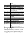
TABLE OF CONTENTS
INTRODUCTION TO THE T35-GFX: A TOOL TO MEASURE AND CONDITION
YOUR CELLS
4
WARNING
4
HOW TO USE THIS MANUAL
5
QUICK START: A STARTING LINE VIEW OF THE T35-GFX
5
PREPPING THE T35-GFX FOR USE.......................................................................................................... 5
POWERING UP THE T35-GFX................................................................................................................. 6
GETTING FAMILIAR WITH THE T35-GFX MENU SYSTEM........................................................................... 6
THE HELP LINE.................................................................................................................................... 8
LOADING FACTORY SETUPS.................................................................................................................... 9
CONNECTING YOUR PACK AND MOTOR....................................................................................................... 9
QUICK START: CHARGE..................................................................................................................... 10
QUICK START: DISCHARGE................................................................................................................. 10
QUICK START: CYCLE........................................................................................................................10
QUICK START: MOTOR RUN.............................................................................................................. 11
LEARNING ABOUT CELLS AND PACKS FOR R/C RACING
11
TYPES OF CELLS USED IN R/C RACING.............................................................................................. 11
RC RACING IS DIFFERENT FROM OTHER BATTERY APPLICATIONS............................................................ 11
HOW CAN CELL AND PACK CAPACITY BE MEASURED AND COMPARED?................................................. 12
SETTING UP TESTS AND COMPARING DATA............................................................................................. 12
TO RECAP… .................................................................................................................................... 14
USEFUL PARAMETERS FOR MEASURING PERFORMANCE............................................................................. 14
MAXIMIZING PERFORMANCE: WHAT HELPS, WHAT DOESN’T.................................................................. 16
UNDERSTANDING CELL RATING AND MANUFACTURER’S SPECIFICATIONS.................................................... 16
HOW TO DETERMINE STARTING POINTS FOR CHARGE RATES, DISCHARGE RATES, AND PEAK DETECT SETTINGS
.........................................................................................................................................................16
USING SIMULATED DISCHARGE PROFILES TO CONDITION PACKS................................................................ 20
ZAPPING: WHAT IS IT AND WHAT DOES IT DO?......................................................................................... 21
EXTREME DISCHARGE/EQUALIZING........................................................................................................ 21
GETTING THE MOST OUT OF YOUR CELLS DEPENDS ON DRIVING SKILL...................................................... 21
HMMM: IT SOUNDS COOL, BUT IS IT USEFUL? GIMMICKS, TRENDS AND SUPERSTITION.................................. 21
FINAL ADVICE (FOR NOW…).............................................................................................................. 22
RESOURCES ON THE WEB................................................................................................................... 22
THE T35-GFX IN DETAIL
22
2
WHAT CAN I DO WITH MY T35-GFX?
22
THE MODE BUTTON........................................................................................................................23
THE PAGE BUTTON......................................................................................................................... 24
THE START/STOP BUTTON........................................................................................................... 24
THE ROTARY DIAL SWITCH AND THE CURSOR..................................................................................... 25
REINITIALIZING NON-VOLATILE MEMORY.............................................................................................. 25
CHARGE MODE..................................................................................................................................25
CHARGE POWER DISSIPATION LIMIT...................................................................................................... 26
SETTING UP A CHARGE CYCLE................................................................................................................ 26
DISCHARGE MODE............................................................................................................................. 29
DISCHARGE POWER DISSIPATION LIMIT.................................................................................................. 29
SETTING UP A DISCHARGE CYCLE............................................................................................................ 29
CYCLE MODE.................................................................................................................................... 33
SETTING UP A CYCLE........................................................................................................................... 33
MOTOR RUN MODE........................................................................................................................... 33
SETTING UP THE MOTOR RUN CYCLE.....................................................................................................34
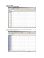
DATA MODE...................................................................................................................................... 34
COMM SETTING...................................................................................................................................35
USING THE GRAPHING FEATURES........................................................................................................... 40
SUPPLY VOLTAGE................................................................................................................................41
SETUP MODE..................................................................................................................................... 41
WHAT SETTINGS ARE SAVED/RECALLED IN A SETUP?.............................................................................. 41
STORING/RETRIEVING SETUPS............................................................................................................. 42
LOADING SETUPS................................................................................................................................ 43
SAVING SETUPS...................................................................................................................................43
NAMING/RENAMING SETUPS................................................................................................................. 44
EDITING SETUPS.................................................................................................................................. 44
BEEPER.............................................................................................................................................. 44
MACHINE........................................................................................................................................... 45
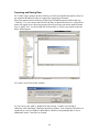
USING THE PC AND HELPER PROGRAMS................................................................................................. 46
HYPERTERMINAL QUICK START............................................................................................................ 47
CAPTURING AND SAVING DATA............................................................................................................. 48
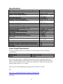
SPECIFICATIONS
56
POWER SUPPLY REQUIREMENTS.......................................................................................................... 56
WHEN IT DOESN’T WORK
57
COMMON PROBLEMS AND QUESTIONS.................................................................................................. 57
NONVOLATILE MEMORY CORRUPTION...................................................................................................... 57
FAILURE TO POWER UP CORRECTLY; GARBLED DISPLAY ............................................................................. 57
FUSES................................................................................................................................................ 58
VOLTAGE DROP, RESISTANCE, AND THE PROPER USE OF SENSE LEADS...................................................... 59
SHOULD I SEND MY T35-GFX IN FOR CALIBRATION?............................................................................. 59
SENDING YOUR T35-GFX IN FOR REPAIR........................................................................................... 59
FIRMWARE UPDATES.......................................................................................................................... 60
***LIMITED WARRANTY***.............................................................................................................. 61
3
HOW TO CONTACT COMPETITION ELECTRONICS.................................................................................. 61
4
Introduction to the T35-GFX: A Tool to Measure and
Condition your Cells
Congratulations on your purchase of our Turbo35 GFX! The T35-GFX is a state-of-theart, competition-grade battery charger/discharger/motor run machine. If you are new to
the T35-GFX it will take a while to become fully familiar with its many advanced
features. However, the T35-GFX is designed so that its basic functions are easy to use,
right out of the box.
If you’ve used other CEI products, you’ll feel right at home with the T35-GFX. However,
if you’ve used earlier CEI products, you’ll find that the T35-GFX also has many new,
exciting and useful features that you won’t find on our competitor’s products.
In order to get the most out of your T35-GFX, please take a moment to familiarize
yourself with this manual.
Warning
To reduce the risk of injury, use only rechargeable nickel cadmium or nickel metal cells
and packs with the T35-GFX. Any other type of battery may burst and cause personal
injury.
DO NOT leave the T35-GFX unattended. The remote possibility of an electronic failure
could cause extreme overcharge. This could cause a cell to burst and cause a fire hazard.
The T35-GFX is designed to provide data about rechargeable nickel cadmium and nickel
metal batteries. In order to simulate high discharge rates obtained during racing, the T35GFX is designed to discharge at high currents. While the methods used in the T35-GFX
are common in selecting cells, excessive heat generated during the process may cause
damage to the cells or cause them to vent battery acids. To reduce the risk of injury,
ALWAYS WEAR SAFEY GLASSES when operating the T35-GFX. Since the cells are
extremely hot, be careful not to handle the cells until cooled.
Always make sure all the cells in the pack are in the same state of discharge before
charging a pack. Otherwise, the cells that are partially charged before charging will get
extremely hot and may be damaged or vent battery acids.
Check your battery pack occasionally for overheating. If the cells are too hot to touch,
there is something wrong and the pack must be disconnected from the charger.
Competition Electronics, Inc. shall not be liable for any property damage or personal
injury which may result from the failure to follow these instructions or other improper
use of this product.
How to Use this Manual
This manual is divided into several parts.
• Quick Start: If you can’t wait to use your T35-GFX, go here. Come back later
when you want to get into the details.
• Learning about Cells, etc: This section contains useful background information
about cells and packs, and how to get the most out of them.
• What can I do with my T35-GFX?: Look in this section for more detailed
operating instructions.
5
•
•
Specifications: This section contains a concise technical summary of the T35GFX capabilities and requirements data.
When it doesn’t work: In this section you learn how to tell if your T35-GFX is
broken, and what to do about it. Also, look here for information about how to get
your T35-GFX upgraded, calibrated, etc.
Quick Start: A Starting Line View of the T35-GFX
This section of the manual will get you up and running fast.
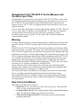
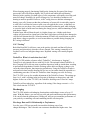
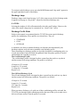
Prepping the T35-GFX for use
If your T35-GFX is new out of the box, you will need to configure the power and output
lead wires. CEI supplies heavy duty alligator clips for these lead wires; they must be
soldered to obtain a good connection. Alternately, you may choose to install some other
type of connector, such as a Dean’s® connector for the power connections.
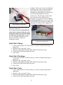
When soldering, be sure to heat the conductors enough so that you get a nice shiny solder
joint. Use enough solder to fully wet the conductors, but not so much that it forms a big
ball, or glob.
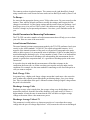
Good solder joints are shiny, not dull. Dull solder joints are usually referred to as “cold”
solder joints. The usual cause is not heating the conductors to be soldered sufficiently
before applying the solder.
Figure 1. Soldering an alligator clip.
6
Remember to put the alligator clip insulators on the wires before soldering the alligator
clips, and make sure they’re far enough away from the solder joint so that they don’t
overheat and melt.
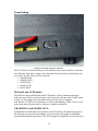
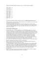
Powering up the T35-GFX
The 14 gage 4 foot long pair of leads on the left side of the T35-GFX are to be connected
to the DC power supply. The other leads are used to make connections to your pack or
motor.
Avoid using the switch on an outlet strip or the line cord plug on the AC side of your
power supply as a means control power to the T35-GFX. Instead, always make the final
power connection to the T35-GFX AT THE DC INPUT WIRE on the power cable of the
T35-GFX.
After terminating the lead wires, connect the T35-GFX power leads to a 12V-16V DC
power supply. Obviously, the red lead goes to the positive terminal; the black lead to the
negative terminal of the supply. This DC supply should be capable of 20 amps if you
want to utilize the full motor run capacity and 12 amps to realize the full charging
capacity of the T35-GFX. See “Power Supply Requirements,” below, for more details.
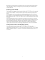
Getting Familiar with the T35-GFX Menu System
Like many digital electronic devices, the T35-GFX has an LCD display that
communicates the status of the T35-GFX to the user. By this means, the T35-GFX menu
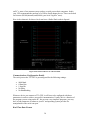
system is displayed. Below is a “menu tree” showing the navigation pattern for the T35GFX menu.
7
CHARGE
MODE
PAGE
PAGE 1
PAGE
1ST PAGE
SETUP
MAIN SCREEN
PAGE 2
2ND PAGE
SETUP
PAGE
PAGE 3
TRICKLE
DELAY START
PAGE
MODE
DISCHARGE
MODE
PAGE
PAGE 1
PAGE
SETUP
MAIN SCREEN
PAGE
MODE
PAGE
MODE
CYCLE
MODE
PAGE 1
SETUP
MAIN SCREEN
PAGE
MODE
MOTOR RUN
MODE
PAGE
PAGE 1
SETUP
MAIN SCREEN
PAGE
MODE
DATA MODE
PAGE
MAIN SCREEN
PAGE 1
PAGE
GRAPHS &
READINGS
PAGE 2
READINGS
PAGE
MODE
PAGE
SET MODE
MAIN SCREEN
PAGE 2
LOAD, SAVE
AND NAME
10 SETUPS
PAGE
Figure 2. T35 GFX Menu Tree.
8
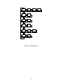
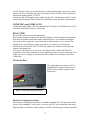
When you first turn on the T35GFX, the display will show the
sign-on message, including the
firmware revision number.
This number corresponds to the
version of software in the T35GFX. From time to time, CEI
upgrades this software, either to fix
firmware “bugs” or to add new
features. The firmware revision
number may be important if your
Figure 3. Sign-on Screen.
T35-GFX needs service; see “When
it doesn’t work” for more details
about this.
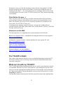
The T35-GFX has three buttons on the front panel, as well as a combination rotary
dial/push button. The buttons are as follows:
Figure 4. T35-GFX front panel controls.
Start/Stop: used to start and
stop the selected function.
Mode: This button is used to
cycle through the six main
functions, detailed below.
Page: This button will cycle
through the various screens
associated with each function.
Use the Mode and Page buttons
to navigate to the desired page,
or screen containing the
parameter(s) you want to view or
change. In either case, when you
get to the last Mode or Page,
pushing the button again will go
to the first Mode or Page of the
series.
As you advance from page to page, individual lines appear on each page. Upon entry to a
page, the top line will be highlighted, indicating it is the currently selected line.
To navigate to individual lines on a page, use the large rotary dial; just push it in to
navigate to the next line on the display.
Some values are adjustable, and some are simply informational and cannot be changed. If
you are on a line that can be adjusted, in general, rotating the dial CW or CCW will
increase/decrease the value.
The Help Line
As you highlight the various lines, a context sensitive, scrolling help line will appear at
the bottom of the display. You can always see the details for the selected line, such as
what range it can be adjusted over, etc. Also, if applicable, you will see additional
9
directions for adjusting the highlighted line, such as when you are creating names for
setups, for example. Use of the buttons varies from the norm on some lines, and details
are given for use when it is appropriate. So, you never really need the directions, once
you’ve got a grasp of the basic use of each function. Just refer to the help line.
Loading Factory Setups
A lot of users have questions about how to set up their T35-GFX for different types of
packs and motors. In order to get you started, the T35-GFX comes from the factory with
a number of standard setups already in the unit. The setups are good starting points for
many common needs. This is the quickest way to get started.
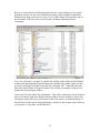
Use the Mode button to navigate to the “set mode” display (shown in the upper right
hand corner of the LCD display. The top line will be highlighted; by rotating the dial, you
can select one of the presets and by pressing the “start” button, you can load it into the
T35-GFX memory for use.
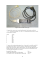
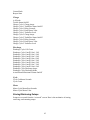
The factory settings are:
1. 6CellNimH: for a 6 cell, 3300mAHr pack.
2. 8CellTx: for a 8 cell transmitter pack
3. 4CellRx: for a 4 cell receiver pack
4. 4CellNimH: for a 4 cell 3300mAHr pack.
5. 6CellCyc: setup to run a charge/discharge cycle for a 6 cell 3300mAHr pack.
6. 4CellCyc: same thing for a 4 cell 3300mAHr pack
The remaining 4 setups are left unused by CEI and you can use them for your own
custom setups. You can also edit and save the factory setups; just be aware that if you
need to reload the factory setups, anything you have saved will be lost. However,
normally you only need to do this if you want to return to the factory setups, or if the
onboard non-volatile memory gets corrupted, which is rare indeed.
Load the factory preset cycle that most closely matches what you want to do. Then,
if necessary, adjust individual settings to “tweak” the setting to your liking. If you don’t
know much about how to set the various parameters, the preset cycles are a good starting
point. As you learn more about the charging and discharging of cells, you can make
adjustments as you wish.
If you are using the T35-GFX with something other than these more standard cell types,
the charge and discharge rates will depend on the mAHr rating and the application the
cells are being used in.
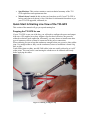
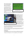
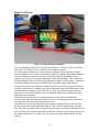
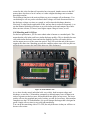
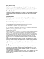
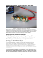
Connecting your pack and motor
First of all, you’ll notice that your T35-GFX has four leads. This is no accident. One of
the things that set your T35-GFX apart from the competition is that it has a set of
separate, smaller “sense leads”. Why? Ohm’s law tells us that where there is a higher
current flowing, there will be a greater voltage drop across any resistance in the circuit
under observation. In this case, most of the unwanted voltage drop occurs directly at the
mechanical connections between the large, hi-current leads and the battery pack. This can
be minimized by making better connections, but the fact is that there will always be a
voltage drop at the connections, because of the high current flowing during charge or
10
discharge. That is why we have the additional
small sense leads. These leads are designed
specifically for measuring, and will have
essentially no voltage drop at all, because the
current flowing through these leads is
relatively low. The advantage of this is that
they can measure the voltage far more
accurately. So in general, it’s best to always
use the sense leads. However, the sense leads
are not absolutely necessary for a charge cycle.
Although the readings will be slightly off, it
Figure 5. Motor Connections.
will not affect the amount of charge
delivered to the pack.
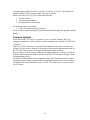
And another thing: it is critical that the
sense leads be connected directly to the
pack/motor solder tabs, and not clipped
or soldered to the large leads. If you do
this, you will defeat the purpose of the
sense leads and they will do you
absolutely no good.
Figure 6. Pack Connections.
Quick Start: Charge
1. Load a setup from the T35-GFX memory, or use the currently loaded setup, if
appropriate.
2. Navigate to the “chg mode” screen.
3. Make any adjustments that might differ from the stock factory setup.
4. Connect Power and Sense leads to the pack.
5. Press “Start”.
Quick Start: Discharge
1. Load a setup from the T35-GFX memory, or use the currently loaded setup, if
appropriate.
2. Navigate to the “dcg mode” screen.
3. Make any adjustments that might differ from the stock factory setup.
4. Connect Power and Sense leads to the pack.
5. Press “Start”.
Quick Start: Cycle
1. Load a setup from the T35-GFX memory, or use the currently loaded setup, if
appropriate.
2. Navigate to the “cyc mode” screen.
3. Make any adjustments that might differ from the stock factory setup.
4. Connect Power and Sense leads to the pack.
11
5. Press “Start”.
Quick Start: Motor Run
1. Navigate to the “mot mode” screen. There are no specific factory cycles for motor
run, although values are saved and included in all setups.
2. Using the “Page” button, go to the “1 of 1” motor parameter screen and select the
motor voltage and run time.
3. Connect Power and Sense leads to the motor.
4. Press “Start”.
After you get up and running, be sure to read the rest of the manual. Do it while your
charging those high capacity NimH packs; you’ll be glad you did.
Learning about Cells and Packs for R/C Racing
One of the hurdles for beginning R/C racers is gaining a basic understanding of these
power sources we call cells. It turns out that the cells we use, and how we treat them has
a huge effect on racing performance. The objective of this section is to give you that
basic understanding.
The technology that makes R/C racing possible is the advent of rechargeable cell types
that are capable of sustained high rates of discharge. It is probable that R/C racing as we
know it could not exist if this technology had not been discovered.
Types of Cells Used in R/C Racing
There are two main types of cells used in R/C racing today.
NiCd: NiCd stands for Nickel-Cadmium. Until the last few years, NiCd was the most
popular cell used for R/C racing.
NiCd cells have a typical cell voltage of 1.2 volts. Among their disadvantages is the fact
that they have a “memory” and if they are not routinely discharged completely and
recharged fully, their capacity diminishes considerably.
Another disadvantage of NiCd chemistry is that they require special disposal procedures
because of their cadmium content.
They are a bit more durable than NimH cells and can stand a bit more abuse, but their
mAHr capacity is considerably lower than NimH types. They are more consistent in their
charge/discharge characteristics from cycle to cycle.
NimH: NimH stands for Nickel-metal-Hydride. NimH is by far the predominant cell in
use today for R/C racing. NimH chemistry does not suffer from any of the disadvantages
of NiCd. It is less toxic, does not have a memory, and now comes in higher mAHr
capacity than the NiCd types.
Today’s NimH cell voltage after “zapping” (we will discuss zapping a little later) have
significantly higher average voltages.
NimH cells should still be recycled at the end of their useful life.
RC Racing is different from other battery applications
If you talk to a cell manufacturer about the way R/C racers charge and discharge their
cells, he or she may tell you that you are abusing these cells. The fact is, to a certain
12
extent, this is true. However, the goals of an R/C racer are different than the goals of an
average user. In the case of the R/C racer, there is the need to balance cell longevity with
performance. It is an inherent tradeoff racers make, so you should understand from the
beginning that racers don’t treat their cells “nice”. As a result, they cannot be expected to
last as long as they might in a less demanding application. If you are interested in
ultimate performance, plan to relegate older packs to practice duty after they have been
used for a while. Exactly when you do this is a function of your skill level and how much
you are willing to spend on cells.
How can Cell and Pack Capacity be Measured and Compared?
Pack performance is one of the crucial make-or-break factors in R/C racing. The best
drivers can use every extra bit of voltage and current available from the best packs.
Because NimH and NiCd cells can vary considerably from cell to cell, and because their
performance can degrade or change depending on how we treat them, how old they are,
etc, we need a way to measure and compare our cells in order to identify the best cells, as
well as the best procedures for charging, discharging, and using them. The T35-GFX is
designed to do just that.
Setting up Tests and Comparing Data
The best way to test and measure cell performance is to set up defined conditions for
charge and discharge, and then run these tests on cells to see which cells are the best.
When you do this, it is also important to be aware that the very conditions under which
they are charged and discharged have a direct effect on their performance.
Basically, the idea is to run these tests on cells, looking for the ones that have the highest
average discharge voltage, the lowest internal resistance, and the longest run time.
In general, when charging, you’ll want to strike a balance between a high charge rate
(which minimizes charge time) while keeping cell heating within bounds.
When discharging, you’ll want to try to use the highest discharge rates applicable to the
cell type you are using, in order to test it under conditions similar to actual use. The T35GFX can sustain a 35 amp discharge rate.
Racers often ask what will be the effect of increasing the charge current, lowering the
peak detect voltage, etc. The T35-GFX is the perfect tool for getting answers to all these
questions! Which manufacturer’s cells perform better? What rate should we charge at?
All these things can be tested and answered by the racer using the T35-GFX.
You can use it to test single cells or packs.
13
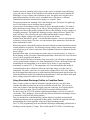
Single Cell Testing
Figure 7. T35-GFX with Single Cell Holder.
If you’re planning on doing a lot of single cell testing, you will want to get a cell holder
from CEI, #CEI -2090. See our website for this and other products.
To use the optional battery box, connect the large alligator clips to the bare 14 gauge
wires on the battery box, (red to red and black to black) or install a high quality connector
of choice. Whatever connector you choose should be rated for continuous current
capacity of 35 amps if you intend to discharge at full rated capability. Then, connect the
small red alligator clip to the small red lead on the cell holder, in like manner, connect the
small black alligator clip to the small black lead. The small voltage leads must be
connected to get accurate discharge readings. DO NOT increase the length of the battery
box high current leads, or introduce any type of additional connection other than the main
connection formed with the end of the leads. To do so may cause discharge current to
taper off at the end of the discharge, due to additional voltage drops introduced by the
additional series resistance.
Mount the end of the battery box with the springs to a flat surface with the holes
provided. The other end of the box is left free to move. Do not tighten the screws all the
way, otherwise the battery box will not move freely.
The battery box may be forced open by squeezing the spring at the end of the rods and
the box between the thumb and the forefingers. This is useful for placing the cell in the
box. The positive terminal of the cell goes to the red lead end of the box. Rotating the cell
back and forth a few times after placing it in the box will insure good connection between
the contacts and the cell. To remove the cell, place your finger underneath the cell and
push up.
14
The contacts used are tin-plated contacts. The contacts can be (and should be) cleaned
using a model train track cleaner for brass tracks such as Rail Zip® made by Pacer Tech.
To Recap…
So, start with the appropriate factory preset. Talk to other racers. Do your research on the
internet. Then, take an old pack and start to modify the settings, and keep track of the
changes in a notebook. Log the charge settings and the results when you discharge. And
don’t forget to try it in your car! That’s where “the rubber meets the road,” so to speak.
Look for a change in your personal performance. Over time, you’ll find what works for
you.
Useful Parameters for Measuring Performance
The T35-GFX can make a number of useful measurements that will help you to evaluate
your cells. Here are some of the most useful.
Actual Internal Resistance
The actual internal resistance measurement made by the T35-GFX conforms closely (not
exactly) to the ANSI standard C18.2M-1997 for sealed rechargeable batteries. It is a
measure of the internal resistance of the pack or cells and will correspond to the packs
ability to deliver power. It is presented in units of milliohms (1/1000 of an ohm) and it is
measured during the discharge cycle. A lower number is better. There is no hard and fast
rule concerning at what rate to discharge cells when making this measurement, but in
general, to get the best comparison data, it’s a good idea to discharge packs at the same
current rate.
It is good to keep in mind that this measurement will include resistance in the
connections between cells, etc. Make sure that you test packs and cells under similar
conditions. For example, use the same method of connecting to cells for all the packs or
cells you want to compare.
Peak Charge Volts
In a general way, a higher peak charge voltage means that it took more volts across the
pack to induce the setpoint current through the pack during charge, for a given charge
rate. This is an indication of the pack’s internal resistance and age; higher voltage means
the pack is less desirable.
Discharge Average Volts
Discharge average volts is simply that, the average voltage over the discharge curve,
measured at intervals, from the start of the discharge cycle until cutoff. Of course, a
higher number is better because it means that the cells will deliver a higher average
voltage to the motor. More volts means more power.
Discharge Average Volts at 1V
This parameter is useful in this way; that most people won’t care about the average
voltage after the per-cell voltage drops below 1 volt, because the cells are too discharged
15
to provide useful power. It will result in a higher number than Discharge Average Volts
and represents the voltage over a more useful range.
Run Time
How long from the start of discharge until cutoff at the set discharge current? Longer is
better, if you need the time. If your races are short, that means that the pack could have
delivered more power if it was required. Maybe changing to a higher current motor, or
changing the gearing might give you more performance by allowing you to utilize more
of your pack’s stored power.
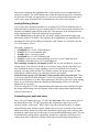
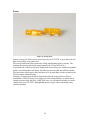
mAHr
mAHr (milliAmpere-Hours) is the capacity
of a cell or cells expressed as the product of
the discharge current in milliamperes times
the time it delivers this output current in
hours. (a mA is 1/1000 of an ampere.)
Manufacturer’s mAHr rating on the types
of cells R/C racers use is typically printed
right on the cell jacket. mAHrs can flow
into or out of the cell; in other words, we
can use mAHr to describe the rate of
charging or discharging. Due to the built-in
inefficiency of power transfer into and out
of the cell, it will always take more power
to charge up a cell or pack than the cell or
pack can deliver into a load.
You can use this to figure out how long a
pack can supply a given current before it is
spent.
Figure 8. Close up of 3300 mAHr cells.
mWHr
mWHr (milliWatt-Hours) is a measure of the power the cell can deliver over time. It is
measured and calculated in the T35-GFX by making a measurement of the output voltage
for a periodic mAHr rate, and multiplying the voltage measurement times the mAHr for
that time period, and totaling the result for the duration of the discharge period until
cutoff.
Relative Internal Resistance
Relative internal resistance was developed by Jeff Pack (a programmer and racer) as a
way of making cell comparisons related to the internal resistance of a cell. You can use it
to compare packs; a lower number is better.
In order to measure this parameter, a full charge/discharge, also known as a Cycle, must
be run. In order to get comparative numbers, you must use similar settings for charge and
discharge current across packs to be compared.
16
It has been largely replaced by Actual Internal Resistance, another CEI innovation in R/C
racing competition-grade equipment.
Maximizing Performance: What helps, what doesn’t
Understanding Cell Rating and Manufacturer’s Specifications
If you buy your cells from a distributor or matcher, you may not have thought about the
fact that they are a middle man to the manufacturer. Google for the manufacturer’s
website; you may find valuable information concerning the cells you are using.
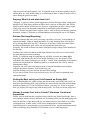
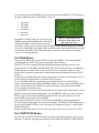
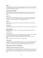
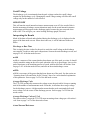
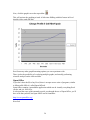
Charge and Discharge Rates and the “C” Rating
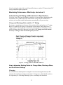
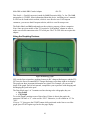
For instance, manufacturers of storage cells rate their cells by giving them a “C” rating.
Below is a graph of cell voltage vs. percentage of full capacity charge input for a 1C
charge rate for a 3300 mAHr sub-c cell. This is related to the rate of discharge current
which will empty the cell of charge in 1 hour. So, a “1C” charge rate is the current
necessary to charge a dead cell to full capacity in 1 hour.
Figure 9. 1C charge profile for 3300 mAHr NimH Cell.
How to determine Starting Points for Charge Rates, Discharge Rates,
and Peak Detect Settings
Charging
So, at what current should packs be charged? For more normal applications (not R/C
racing!), the manufacturer might recommend a 1C charge rate, which should result in a
life expectancy of >500 charge/discharge cycles, according to the data sheet.
17
For smaller capacity cells, it’s probably a good idea to stick to 1C charge rates, but as the
cell capacity gets larger, the cell can handle higher rates.
For another, there is some evidence to indicate that a higher charge rate will result in
better performance on the track. Racers routinely charge these cells at 5A (5000mA) and
better. One racer likes to charge his high capacity NimH cells at 10A (better than a 3C
charge rate) because he claims that it improves the performance!
Peak Detect
Notice the little voltage “hump” at the 1C point in the graph above, followed by the drop
in voltage. This is called “peaking” and this is the method used by many chargers,
including the T35-GFX, to determine when the charge is finished. When you set the peak
detect voltage in the T35-GFX, you are telling the T35-GFX to terminate the charge
when the voltage drops back from the peak, or maximum voltage seen during the charge
process, by the peak detect amount. If you use the T35-GFX graphing feature to look at
the charge curve, you will be able to see this hump for yourself.
The actual peak rate of change and the magnitude of peak negative dropback voltage are
highly dependent on the charge current. At charge rates of, say, 0.5C and below, the peak
negative dropback voltage may be too small to serve as a reliable indicator of charge
completion.
A typical value for peak detect for a NimH pack is 0.007 to 0.010 V/cell, or 0.04 to 0.06
volts for a 6 cell pack. The value for a NiCd cell will be somewhat higher, typically 0.008
to 0.013 V/cell, as the NiCd cell exhibits a larger peak negative dropback voltage than a
NimH. CEI recommends using the lowest value required to reach a temp of 130° to 140°
F.
False Peaking
As you can see from the graph, the voltage at the start of the charge cycle will jump up
some amount as current is applied. Then, the voltage will “level out” for a while, or
slowly rise. It is at this point that NimH (and NiCd) packs often exhibit a characteristic
called “false peaking”. The pack voltage will actually drop, even though the pack is not
yet near full charge. This effect can be magnified if “dead shorting” or deep discharging
the battery. If you are not aware of this, you may think your packs are fully charged, but
in reality, they are only partially charged. If your pack appears to have peaked too soon, a
quick test is to feel the pack to see if it is warm. If it is not good and warm, that means
that the pack false-peaked and is not fully charged. If the T35-GFX indicates something
less than the 1C mAHr rating has been delivered to the pack, it is almost a certainty that
the pack has false peaked.
False peaking can be overcome in the T35-GFX by using the “Long Lockout” feature to
cause the T35-GFX to ignore voltage drop across the pack at the beginning of the charge
cycle. It will automatically re-enable its peak detect monitoring after the time for false
peak rejection has expired. This has proven to be quite reliable as a method to avoid false
peaking. It eliminates the hassle of having to restart the charge cycle because the pack
false peaked.
Cell Heating
18
When charging properly functioning NimH packs, during the first part of the charge
process the cells will self heat slightly. NiCd cells do not exhibit this self-heating
behavior before peaking. For both types of cells, temperature will rapidly rise as the pack
nears full charge. Normally, for good cell longevity, it is desirable to minimize cell
heating as much as possible. However, in R/C racing, there are definite advantages to
heating your cells! It turns out that the performance of warm cells is noticeably superior
to cold cells. It will then be better to peak your cells right before a race, so that they are
warm when you use them. Also, some racers thermally insulate the pack while charging,
to cause the pack to build more heat during the charge process, while maintaining a lower
peak detect voltage.
Another factor that will heat the pack is a higher charge rate. A higher peak detect
voltage will also result in a hotter pack. But don’t forget that excess heat does damage the
cells and will shorten their life. Normal treatment of NimH cells would dictate as small a
peak detect voltage as possible, to avoid as much heat as possible during charging, but
R/C racing is different!
Cell “Venting”
Both NimH and NiCd cells have vents at the positive electrode end that will release
pressure (and electrolyte) when the cells are charged. This venting is normally to be
avoided. It will occur at higher charge rates. Repeated venting will certainly degrade
cells.
TurboFlex: What is it and what does it do?
Your T35-GFX includes a feature called “TurboFlex”, also known as “burping”.
TurboFlex is only intended for use with NiCd cells. The rationale behind TurboFlex is
this: Charging NiCd cells can cause crystalline deposits to build up inside them, resulting
in performance degradation. Periodic discharge pulses delivered during a charge cycle
can reduce these deposits, thus improving performance. Using the TurboFlex feature is
not beneficial when actually charging for use in a car, but rather should be regarded as a
conditioning procedure. Do not use TurboFlex when charging your cells for racing.
The T35-GFX is set up for variable adjustment of the TurboFlex feature. The settings go
from 1 to 9, with 1 resulting in the lowest ratio of discharge to charge time, and 9 the
highest. In the case of the T35-GFX, the TurboFlex discharge rate is fixed at 5 amps.
TurboFlex will not take place, regardless of the setting, if the charge current is <= 3A.
This is built into the T35-GFX.
Discharging
The T35-GFX includes a discharging function that can discharge at rates of up to 35
amps. With this feature, you can test your cells and packs and measure their performance.
You can tell when the performance is falling off, and you can extend the performance of
your packs by re-matching cells and combining similar cells into packs.
Discharge Rate and It’s Relationship to Performance
Over the years, CEI has repeatedly increased the discharge rate of our
charger/dischargers. This is because our customers demanded the higher rates. One
19
reason for this is the fact that cell capacities have increased. Another reason is that R/C
motors these days draw a lot of current, so it takes a higher discharge rate to emulate
these high currents.
The discharge function is the main tool that you use to compare cell performance. You
can discharge a cell or a pack to a defined cutoff voltage at a fixed current and observe
the discharge voltage over time as a graph, as well as time the discharge duration.
Obviously, a rather simple application of this, and one that is used most frequently, is to
run the identical discharge procedure on several similar packs and compare the results.
More run time is better, of course, but a higher output voltage is better, as well.
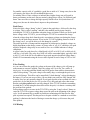
Cell Matching and it’s Effects
For the best performance, you’ll want to obtain what is known as a matched pack. This
means that the cells in the pack have similar discharge profiles. This is desirable because
cells with similar discharge times and similar discharge profiles will tend to deliver
similar output power over the same time period. They will reach the end of their power
output at the same time. Matching prevents the condition where some cells in a pack are
still delivering current to the load while others are fully discharged.
Figure 10. TurboMatcher 4/35.
As we have already stated, individual cells vary widely, both in output voltage and
discharge, or run time. Cell matching companies go through many cases of batteries in
order to separate out the best ones, and match them into packs for top racers. The lesser
quality cells are also matched into packs, but they are sold for less money. Most matcher
companies use the CEI TurboMatcher 4 (a special charger/discharger that is designed to
grade 4 single cells at a time) to test cells and match them.
You can do the same thing with a T35-GFX; the only difference is that you will have to
do one cell at a time.
20
Another reason for matching cells is that over the course of multiple charge/discharge
cycles, the state of charge of the individual cells within the pack becomes imbalanced.
Matching is a way to restore and recharacterize (test ‘em again) each cell and even to
gain information that will allow you to recombine these cells into new, different
combinations when their characteristics change; to “rematch” them.
The primary number for matching cells is the discharge time. The object is to gather up
sets of cells with as close a discharge time as possible.
In stock class, the discharge average voltage is also an important number. You want as
high a discharge average voltage as you can get. When grading for stock class, use the
discharge time first as the primary parameter; then use the discharge average voltage as a
secondary parameter. The higher the discharge average voltage, the more “punch” the
motor will have. This is because the pack with a high discharge average voltage is
delivering a higher voltage to the motor for a given period of time.
Another factor that affects “punch” is actual internal resistance. A lower actual internal
resistance is always better. The more you can maximize these parameters, the better the
motor performance will be.
When using packs with modified motors, the actual internal resistance should become the
second parameter to grade by. The discharge average voltage is not as important because
you can always go to a lower wind (read: lower impedance) motor to compensate for the
lower voltage.
Remember that when you are testing new packs, always cycle the packs 3 or 4 times at
the beginning, so that you achieve maximum performance from each cell. New cells need
a few cycles to properly break them in.
In order to achieve the best performance from your packs, you will need to determine the
correct peak detection voltage to use when charging them. Given a sufficient charge rate,
monitoring the cell temperature is an excellent way to do this. A typical peaking
temperature is around 125° F. The temperature rise is an indication that the chemical
reaction that takes place within the cells at the end of the charge cycle has come to
completion. For packs, start with a low peak-detect voltage such as 0.03 volts. Monitor
the pack temperature and increase as needed until the final temperature hits the target. Be
aware that different model cells, and different manufacturer’s cells may differ in the peak
detect voltage required to achieve the desired temperature.
Using Simulated Discharge Profiles to Condition Packs
There is some evidence to indicate that packs respond to the way you drive them.
Consider the difference between an oval racer and the off road racer. The oval racer
settles into a pattern: Jam down the trigger going out of the turn, let off going into the
next turn, then do it again. The off road racer has an entirely different pattern.
For this reason, the T35-GFX includes conditioning discharge cycles for oval and off
road racing. These discharge cycles periodically increase and decrease discharge current
to simulate oval and off road racing patterns.
They are intended for conditioning only, and the display of regularly measured and
calculated parameters are not supported in these modes. So don’t be surprised when the
measured data don’t look right after using one of these discharge modes.
The T35-GFX programming locks out simulated discharge conditioning profiles below a
discharge current setpoint of 3 amps. This is built into the T35-GFX to avoid drawing
21
large currents from small capacity cells. You should not try to run these profiles on cells
smaller than, say, 2000 mAHr rating, as it will attempt to draw 45 amps from the cells at
times during the profile execution.
Zapping: What is it and what does it do?
“Zapping” is a process where special equipment is used to discharge a high voltage pulse
through a cell. Each battery matcher will have their own way of doing this, and will not
likely reveal the details of their process. However, zapping does increase voltage output
of the cells, and it is an important component for maximum pack performance.
NOTE: CEI does not make battery zappers, and we want to advise you that they generate
hazardous voltages. CEI makes no recommendations concerning the use of cell zappers.
Extreme Discharge/Equalizing
Another technique that some racers are using, especially oval racers, is the technique of
extreme discharge. Using an equalizing battery tray, they discharge their cells down to
0V by leaving them in the tray for 15 minutes to several days. Some racers then follow
this by dead shorting the pack with a wire and storing their packs this way.
Allegedly, this results in shorter run times, but higher average voltage for the duration of
the run time.
Another effect claimed is that the mAHr input that the pack will receive is increased if
the pack undergoes extreme discharge.
Finally, it is said that using an equalizing tray will help overcome the scatter effect.
Especially with NimH cells, after a few charge discharge cycles, the position of the
individual cells in their discharge curves tend to “scatter” with relationship to one another
and become desynchronized. Equalizing tends to re-synchronize the cells, by entirely
draining their charge.
In general, one may notice that longer periods of extreme discharge result in higher
voltages but shorter run times. Your results may vary.
Extreme discharge may also result in increased false peaking.
All we can say is that if you’re an avid stock racer, you will want to experiment with
extreme discharge.
Getting the Most out of your Cells Depends on Driving Skill
Here’s an undeniable fact: all the voltage and current in the world won’t help you if you
don’t have good driving skills. Only good drivers can utilize the small but real advantage
that the best packs give. If you fit into this category, you need ‘em. If you’re not quite
there yet, maybe you can get away with cheaper packs. You’ll have to be the judge, here.
Hmmm: It sounds Cool, but is it Useful? Gimmicks, Trends and
Superstition
Finally, keep in mind that this is applied science and like any field of knowledge, there’s
such a thing as smoke, mirrors, and snake oil. If somebody tells you that submerging your
packs in milk for a couple hours will give you better run times, don’t believe it. (Unless
you happen to try it and it works!) Look out for manufacturers advertisements that
contain long lists of acronyms that you never heard of before, and that sound nonsensical.
If they seem bogus, they probably are. Remember, you’re a marketing target!
22
Sometimes, racers get in line like lemmings to chase after the latest gimmick. We find
that these gimmicks peter out after a little while, as racers discover that they don’t do
anything (useful, that is…). If you hear about some new technique, feature or device and
you want to know if it works, use the T35-GFX to check it out. Then, instead of guessing,
you’ll KNOW.
Final Advice (for now…)
There’s no way we at CEI could carry out all the research needed to find out the best
ways to charge, discharge, and condition cells to get the very best performance out of
them. The next best way is to give racers a tool to do it themselves, and then turn ‘em
loose with it. The T35-GFX is such a tool.
Technology keeps changing. Capacities increase, cells get more durable and more
powerful. Keep an open mind. Talk to other racers. Use the internet. This way, you’ll find
out what works best for you.
Resources on the Web
The following links are a compilation from various members of the CEI staff.
Batteries in a Portable World: “A handbook on rechargeable batteries for non-engineers”
http://www.buchmann.ca/
GP Batteries Corporate Website: Contains datasheets for some popular R/C cells.
http://www.gpbatteries.com.sg/
Sanyo US: More datasheets here.
http://www.sanyo.com/home.cfm
Panasonic Batteries: yet more datasheets.
http://www.panasonic.com/industrial/battery/
The T35-GFX in Detail
This section of the manual is the place to go to get detailed information on how the T35GFX works and how to use it. See the previous section for detailed information about
what each setting does.
What can I do with my T35-GFX?
The T35-GFX functionality is presented to the user as a set of 6 menu functions, referred
to as MODES. When the T35-GFX is first turned on, it goes through the sign-on screen,
where you see the copyright notice and the firmware revision number. After a short time,
the Charge menu appears. Moving through the various screens of the menu tree is called
navigating the menu tree.
Note the three buttons clustered to the left of the rotary dial/switch on the right hand side.
23
Figure 11 T35-GFX Front Panel Controls.
They are:
•
•
•
START/STOP
MODE
PAGE
The MODE Button
The T35-GFX display can be advanced from one mode screen to the next by pressing the
MODE button. It will move through these modes:
•
•
•
•
•
•
CHARGE
DISCHARGE
CYCLE
MOTOR
DATA
SETUP
24
You can always tell what MODE you are in by observing the MODE STATUS display in
the upper-right-hand corner of the display. They are:
•
•
•
•
•
•
chg mode
dcg mode
cyc mode
mot mode
dat mode
set mode
Figure 12. Typical status screen
Regardless of what PAGE you are on in a given
showing the mode display in the
MODE, pressing the MODE button will always
upper right hand corner.
advance the display to the main screen of the
next mode. There is one exception: when CHARGE, DISCHARGE and CYCLE modes
are active, the MODE button toggles back and forth between the main MENU screen and
the real-time GRAPH screen. Using this feature, you can see the charge or discharge
curve as it is being generated.
The PAGE Button
In any given MODE, one or more SETUP screens are available. You can sequentially
cycle through these SETUP screens by pressing the PAGE button.
The SETUP screens contain adjustable and measured data parameters specific to the
mode selected. For CHARGE, DISCHARGE and CYCLE modes, there are essentially no
settable parameters on the main screen (except for a few exceptions, which we will
discuss later.) In general, parameters for these modes must be adjusted from the SETUP
screens.
For the DATA and SETUP modes, some values can be set from the main mode screen, as
well as from the selected mode’s associated SETUP screens.
So, you can think of this by envisioning in your mind a picture of a vertical list of
screens, which represent the different MODES. When you come to the last MODE screen
in the vertical list, pressing MODE once again will bring you back to the first MODE
screen, which is the charge screen.
For each MODE, you can envision a horizontal list of screens which represent the various
SETUP screens associated with that mode. Like the MODEs, when you come to the last
SETUP screen for the selected MODE, pressing PAGE once more returns you to the
main MODE screen for the selected MODE.
You can tell what PAGE you are on for the selected MODE by observing the PAGE
STATUS display in the upper left corner of the display. The PAGE STATUS displays are
specific to the MODES. Please refer to the menu tree diagram in Figure 1 (earlier in this
manual) for details.
Armed with this information, you’re ready to navigate the menu tree of your T35-GFX.
The START/STOP Button
The function of the START/STOP button can change depending on where you are in the
menu tree. In general, pressing start anywhere from within the CHARGE, DISCHARGE
25
and CYCLE modes will jump directly to the main MODE screen and start that MODE.
Whenever the T35-GFX is executing a CHARGE, DISCHARGE, or CYCLE MODE,
pressing the START/STOP button will stop the MODE execution. In the case of some
parameters, the START/STOP switch will advance sequentially through a line of single
characters, such as when you enter a new name for a setup.
The Rotary Dial Switch and the Cursor
Adjustable parameters appear as reverse highlighted lines on the SETUP screens. This is
referred to as the CURSOR.
Pressing the Rotary Dial Switch
advances the CURSOR to the
next adjustable parameter. When
positioned at the last line,
pressing the Rotary Dial Switch
again repositions the CURSOR
to the first adjustable parameter.
In general, when the CURSOR
is positioned on a parameter,
rotating the Rotary Dial Switch
clockwise increases the setting
Figure 13. Typical selection screen showing the cursor
and rotating counter-clockwise
line.
decreases the setting.
For parameters that require character-at-a time editing, the START/STOP switch
advances to the next character, as was stated above.
Reinitializing non-volatile memory
As mentioned earlier in this manual, the T35-GFX comes from the factory initialized
with ten different setups. Over time, you may modify these setups so much that you’ve
forgotten all the settings you changed, and just want to get back to the default. Or, you
might have encountered corruption in one or more of the stored setups.
In either case, it’s easy to reload the factory default settings. Perform the following steps:
1.
2.
3.
4.
5.
Disconnect the pack or cells from the T35-GFX.
Remove power from the T35-GFX at the DC side of the power supply.
Hold down the “PAGE” button.
While holding it down, re-connect DC power.
Continue holding it down until you see the “SYSTEM INIT” message appear on
the display. Then, you can release the PAGE button; in a few moments, the
charge screen will appear, signifying that the T35-GFX is ready to use.
The re-initialization is now complete.
Charge Mode
The T35-GFX can charge individual cells as well as packs of 2 to 8 cells. In order to
charge 8 cell packs, the T35-GFX power source must be no less than 15 VDC. Under no
circumstances shall the DC supply voltage be allowed to exceed 16 VDC.
26
The main display for the charge mode will show you the currently selected setup, the
pack voltage, the charge rate, the mAHrs delivered to the battery, the elapsed seconds
since the start of the charge cycle, the number of peaks set, the charge current setpoint,
and the status of the Long Lockout and TurboFlex features.
Charge Power Dissipation Limit
The T35-GFX will limit the maximum power dissipated within the charge output power
MOSFETs to 185 watts.
As the charge cycle progresses, the output voltage will rise in order to maintain the
setpoint current, because the pack voltage naturally rises. If the T35-GFX sees that the
charge power MOSFETs have begun to dissipate power in excess of 185 watts, the T35GFX will lower the voltage to bring power dissipation within safe limits. That means that
the output voltage will be limited to the maximum safe value, and the charge current will
drop below the setpoint.
When power limiting is in effect, the display will indicate this by displaying the message
“POWER*LIMIT*ACTIVE”.
The power limit feature cannot be defeated, but in some cases you may be able to bring
the T35-GFX out of power limit mode by reducing the power supply input voltage. Do
not lower the input voltage below 12 volts.
Setting up a charge cycle
As mentioned earlier on this manual, there are 10 stored setups in the T35-GFX. You
may find that one of these setups is ideal. You may also find that one of the stored setups
is a good starting point. You can load one of the setups as detailed in “Storing and Saving
Setups,” below. Otherwise, you can check and set each parameter.
To navigate to the charge screen, press the MODE button until “chg mode” appears in the
upper right hand corner of the display.
If you want accurate numbers from your charge cycle, you must use the smaller voltage
sensing leads. However, if you just want to charge, use of the sense leads for the charge
cycle is unnecessary. The peak dropback voltage will still be accurate; it will just be
offset by the voltage drop of the pack connections.
Charge Rate
Charge rate is the current delivered to the pack during the charge cycle. Units are in
amps. This is how you get power into the pack. To set the charge rate, use the PAGE
button to advance to the page “peak 1”. The page appears with the CURSOR positioned
to the first parameter, which is the “Chg Amps”. Rotate the ROTARY DIAL SWITCH
clockwise to increase the charge current; counterclockwise to decrease the charge current.
The values will cease to change when you reach the built in limits for the parameter.
Make sure that your power supply is capable of supplying the current you select plus a bit
more; the T35-GFX cannot make power out of nothing! Your DC supply must have
sufficient power for the demand.
27
Peak Detect Voltage
Peak Detect Voltage appears on the display as “Peak Det V”. This is the dropback
voltage setpoint at which the T35-GFX will automatically terminate the charge operation.
Units are in volts. Turn the ROTARY DIAL SWITCH to set the Peak Detect volts.
TurboFlex On/Off
TurboFlex On/Off appears on the display as “Turboflex”. This is the setting that turns the
TurboFlex feature On and Off. Rotating the ROTARY DIAL SWITCH will toggle the
setting.
TurboFlex Level
TurboFlex Level appears on the display as “Turboflex Level”. The TurboFlex level
adjusts the discharge rates relative to the charge rate. The discharge rate of the burp is
fixed at 5 amps.
The TurboFlex “burp” takes place once per second.
The duration of the TurboFlex discharge period every second is given by:
(((Charge_Amps*4* Turboflex_Level)+17000)/2)*0.2uSec
So, for a charge rate of 5 amps and a TurboFlex level of 5, the duration of the discharge
burp will be (((5*4*5)+17000)/2)*0.2uSec = 1.71 mSec.
Long Lockout On/Off
Long Lockout appears on the display as “Long Lockout”. Normally, at the beginning of a
charge cycle, the T35-GFX will disregard dropback voltage from the peak voltage
detected up to the present point in the charge process for a duration of 60 seconds. This
allows stabilization of the pack voltage for a short period before peak detection kicks in.
In order to overcome false peaking, Long Lockout can be activated. This will cause
dropback voltage to be disregarded for 10 minutes, beginning at the start of the charge
cycle.
Long Lockout will be reset to OFF after the cycle ends. This is done to avoid, as much as
is possible, putting current into a fully charged pack for 10 minutes, which is what would
happen if you connected a fully charged pack and Long Lockout was ON. Our
philosophy is that the user needs to deliberately turn on long lockout, and then the user
will not arbitrarily make this mistake.
# of Peaks
The T35-GFX terminates the charge cycle when the peak negative dropback voltage is
equal to the peak detect setting. Sometimes, the racer might want to repeak the cell or
pack after the primary charging is finished. Setting the “# of peaks” to 2 will enable an
entire second charge and peak detect.
The settings for this second peak are found on the “peak 2” page in the charge mode. This
includes charge rate (independent from the first peak charge rate), peak detect volts,
turboflex, and delay.
28
Delay
Delay appears on the “Peak 2” page of the charge mode screens. Use it to set the number
of seconds between the first and second peak functions. One reason to use the delay is to
let the pack rest after the first peak.
Interpreting the Results
Much of the data collected and calculated during the charge cycle is displayed on the
pages of the data mode screens. Where that is the case, it will be indicated in the text
below.
Peak Volts
Peak volts is related to the charge function but it is located on page 1 of the data mode
(“dat mode”) screen. This is the highest voltage recorded across the pack during the
entire charge cycle. Seen on page 1 of 2 of the dat mode screens.
mAHr
Charge mAHr is the measure of the power delivered into the pack. Seen on the main
charge screen.
Charge Time
This tells you how long it took to charge your pack. It is found on the main charge screen.
Other Features
Moving from “Peak 2” to the “3 of 3” page exposes several miscellaneous functions,
described below.
Trickle Charge
After the main portion of the cycle is through, setting Trickle Charge to ON will enable a
fixed 100mA current into the pack for the purpose of trickle charging.
The trickle charge will be automatically disabled if the charge current is set below 2
amps.
Trickle, if enabled, will continue until the user stops the cycle.
Delayed Start
Wouldn’t it be nice if you could time your charge cycle so it would finish just before the
race? That’s what this feature is for. Dial in the number of minutes for the delay; then
press start. Your charge cycle will begin that many minutes after you press start.
Miscellaneous Features and Functions
Adjusting Charge Rate during a Charge Cycle
The T35-GFX allows you to adjust the charge rate while the charge cycle is active. One
use for this feature is to speed up the charge if you see that it won’t be done soon enough.
Do not use this if you want accurate readings; it’s just a convenience to shorten charge
time.
29
When you change the charge rate during a cycle, the 60 second lockout will be reactivated to assure that no false peaking results from the changed voltage across the pack
due to a change in charge current.
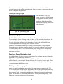
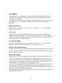
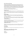
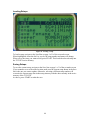
Viewing the Charge Graph
While the charge cycle is in
process, pressing the MENU button
will toggle back and forth between
the main charge screen and the realtime charge graph. More will be
said about the graphing feature later
in this document.
Figure 14. Typical charge graph.
Discharge Mode
The T35-GFX can discharge individual cells as well as packs of 2 to 8 cells.
The main display for the discharge mode will show you the currently selected setup, the
pack voltage, the discharge rate, the mAHrs drawn from the battery, the elapsed seconds
since the start of the discharge cycle, the number of cells in the pack, the discharge
current setpoint, and the discharge profile currently selected.
Discharge is terminated when the pack voltage reaches the cutoff voltage setpoint.
Factory presets are based on a starting point of 0.9 volts/cell, so that in most cases, you
can simply change the # of cells setpoint and the cutoff voltage will be automatically
adjusted to the correct value. However, the cutoff voltage is independently adjustable for
maximum flexibility.
Discharge Power Dissipation Limit
As with the charge function, the power dissipation of the discharge function is limited to
protect the T35-GFX discharge MOSFETs.
A 7 cell pack will be limited to a maximum of 25 amps discharge rate and an 8 cell pack
will be limited to a maximum of 20 amps discharge rate. However, because pack voltage
decreases during discharge, there is no automatic (dynamically adjusted by the charger)
current limiting in the discharge cycle.
Setting up a discharge cycle
Again we remind you that there are a total of 10 setups storage memories in the T35GFX. Only the first 6 are specifically programmed; the rest have generic data which will
almost certainly have to be modified in order to be very useful. You may find that one of
these setups is ideal. You may also find that one of the stored setups is a good starting
point. You can load one of the setups as detailed in “Storing and Saving Setups,” below.
Otherwise, you can check and set each parameter.
30
To navigate to the discharge screen, press the MODE button until “dcg mode” appears in
the upper right hand corner of the display.
Discharge Amps
Discharge Amps can be found on page 1 of 2 of the setup screens for the discharge mode.
It appears on the page as “Dcg Amps”. Adjust for the desired discharge rate.
# of Cells
Selecting the number of cells will automatically select the cutoff voltage. However, the
value of the cutoff voltage may be customized, see “Cutoff Volts”, below.
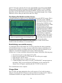
Discharge Profile Mode
Earlier in this manual we mentioned that the T35-GFX has some special discharge
profiles for conditioning. These profiles are selected here. They are:
•
•
•
STANDARD
OVAL
OFF ROAD
A standard cycle draws a constant discharge rate from the pack determined by the
discharge setpoint, and is the most commonly used discharge profile.
These remaining two discharge profiles are specially designed for conditioning packs. As
a result, the measured and calculated data gathered when using these profiles is invalid
and should not be regarded as accurate.
The Oval Discharge Profile
The oval discharge profile is designed to draw current from the pack in a way that is
similar to actual oval racing conditions. The profile is as follows:
45 amps for 1.25 seconds
0 amps for 1.25 seconds
3.6 amps for 1.25 seconds
Repeat Cycle
The Off Road Discharge Cycle
The off road discharge profile is designed to draw current from the pack in a way that is
similar to actual off road racing conditions. The profile is as follows:
45 amps for .25 seconds
0 amps for .25 seconds
22.5 amps for .5 seconds
Repeat Cycle
When you start a discharge cycle with one of these conditioning profiles activated, the
T35-GFX goes through a short calibration period at the start of the cycle to make sure it
delivers accurate current. Then the profile is executed.
31
Cutoff Voltage
The discharge cycle is terminated when the pack voltage reaches the cutoff voltage
setpoint for the discharge cycle. Changing the cutoff voltage setting will affect the cutoff
voltage only for the number of cells selected.
AIR ON/OFF
This will turn the actual internal resistance measurement on or off. One result of this is
that the momentary discharge current alterations made for the actual internal resistance
measurement will not appear in the discharge graph, because they are not made when
AIR is OFF. This will give you a nicer looking discharge graph, if desired.
Interpreting the Results
Much of the data collected and calculated during the discharge cycle is displayed on the
pages of the data mode screens. Where that is the case, it will be indicated in the text
below.
Discharge or Run Time
This is simply the time it takes for the pack to reach the cutoff voltage at the discharge
rate setpoint. Use this to make pack comparisons. Seen on the main discharge screen, and
on page 2 of 2 of the dat mode screens.
mAHr
mAHr is a measure of the current that has been drawn out of the pack over time. It should
closely match the rating on the cell or pack when the cells are in good shape. Later, as the
packs deteriorate or the matching gets out of synch, mAHrs delivered will decline. Seen
on page 2 of 2 of the dat mode screens, and also on the main discharge screen.
mWHr
mWHr is a measure of the power that has been drawn out of the pack. See the section on
“Learning about Cells and Packs for R/C Racing” above for a more detailed explanation
of this parameter. Seen on page 2 of 2 of the dat mode screens.
Average Discharge Volts
The T35-GFX periodically measures the voltage across the pack while it keeps a running
total of the number of measurements made. From this, it calculates the average voltage
for the discharge process. A higher number means that the pack consistently delivered
more voltage over the course of the discharge process. Seen on page 2 of 2 of the dat
mode screens.
Average Discharge Volts at 1 Volt
The same as above, except the T35-GFX stops measuring when voltage per cell reaches 1
volt. Seen on page 2 of 2 of the dat mode screens.
Actual Internal Resistance
32
A pack or cell powering a load can be approximated by a voltage source in series with a
resistance, delivering power to a load, such as a motor. Ohm’s Law
Voltage (volts) = Current (amps) x Resistance (ohms)
tells us that current will decrease when resistance increases. Lower current means in turn
a lower voltage delivered to the motor, which means less power delivered to the wheels.
So, it follows that one important way to compare packs is to measure it’s actual internal
resistance.
It’s called actual internal resistance to distinguish it from relative internal resistance,
mentioned elsewhere in this manual.
In the T35-GFX, actual internal resistance is measured by briefly altering the current at a
predetermined time during the discharge process, and recording the voltage. Having
voltage and current for two different currents, the actual internal resistance can then be
calculated.
From Ohm’s law:
So it follows that:
This is the basic math used by the T35-GFX to calculate actual internal resistance.
The T35-GFX presents actual internal resistance in milliohms. Lower is always better.
Below discharge rates of 5 amps, actual internal resistance measurements cannot be made
with the T35-GFX.
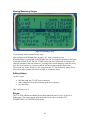
Other Features
Viewing the Discharge Graph
While the discharge cycle is in process,
pressing the MODE button will toggle
back and forth between the main
discharge screen and the real-time
discharge graph. More will be said
about the graphing feature later in this
document.
Figure 15. Typical discharge graph.
33
Cycle Mode
Cycling is just a way of automating a charge cycle followed by a discharge cycle. You
will always have to get charge into a pack before you can get anything out; therefore
cycling is a useful feature.
Cycling makes use of the charge and discharge features already discussed, and so most of
the settings for a cycle are already complete from previous setup sessions already
discussed.
Setting up a Cycle
There are only two parameters to set for a cycle; everything else is set in the charge or
discharge mode screens.
# of Cycles
Simply specifies the number of charge/discharge cycles to be run sequentially. Why
would you want to run sequential cycles? What if you wanted to do extended longevity
testing to get an idea how long a certain type of cell might last before degrading? That’s
just one example; you may think of others.
Cool Down Minutes
When you charge/discharge a pack, it gets hot. If you want to, you can set cool down
minutes so that the pack has enough time to fully cool between cycles.
Relative Internal Resistance
In order to measure relative internal resistance, both a charge and discharge cycle must be
run, thus it is associated with a cycle. However, the actual measurement appears in page 1
of 2 of the data mode pages.
Motor Run Mode
You can use your T35-GFX to break in R/C motors. One of the most useful features of
the T35-GFX for motors is its ability to deliver a full 20 amps of current to a motor!
The motor run feature uses the same output power MOSFETs as the charge feature, and
so has the same power limitations Therefore, to protect the MOSFETs, the motor cycle
will be limited to a maximum power dissipation of 185 watts.
If the T35-GFX sees that the charge power MOSFETs are dissipating power in excess of
185 watts, the T35-GFX will lower the voltage to bring power dissipation within safe
limits. That means that the output voltage will be limited to the maximum safe value, and
the motor voltage will drop below the setpoint.
When power limiting is in effect, the display will indicate this by displaying the message
“POWER*LIMIT*ACTIVE”.
34
Setting up the Motor Run Cycle
To set up your motor run cycle, use the PAGE button to move to page “1 of 1” in the
motor function mode. Here you will find two settings.
Motor Volts
Select the desired motor voltage here.
Run Time Minutes
Select the run time in minutes here.
Using the GFX with a Commutator Lathe
The T35-GFX is useful as the power source for a Commutator lathe, which is used to
reshape the commutator contacts on the armature of your motor, to maximize conduction,
and therefore power to the wheels.
Adjusting Motor Voltage While Running
On T35-GFX units with firmware version 1.60 and above, the user can vary the motor
voltage “on the fly”, that is, while the motor is running. Older firmware revisions that
lack this feature may be upgradeable; visit our website,
http://www.competitionelectronics.com/
…or call CEI for details.
Data Mode
The “dat mode” mode does not contain any cycles. Instead it is a collection of useful
measured and calculated parameters, as well as the place where you access the stored
graphs for the last charge and discharge cycles run on the T35-GFX. Many of the data
mode parameters have already been mentioned in the descriptions of the charge,
discharge and cycle sections; here are the descriptions of the remainder of the
information it contains.
35
Comm Setting
Figure 16. T35-GFX serial port connector.
The T35-GFX has a built in serial port on its side that can be used to transfer certain data
out of the unit. The comm. setting is the setting that selects the format of data being sent
out of the T35-GFX. There are five selections:
• GRAPH MAN
• GRAPH AUTO
• COMP MAN
• COMP AUTO
• REAL TIME
MAN(ual) and AUTO(matic)
The difference between MAN(ual) and AUTO(matic) is that if a manual selection is
made, the user will have to first navigate to the Comm line, then press the START button
to print. AUTO settings will print automatically after the cycle is complete.
Note that the T35-GFX uses no hardware or software handshaking. When it’s time, it just
spits out the data with no regard for whatever it might be attached to.
GRAPH MAN and GRAPH AUTO
GRAPH MAN and GRAPH AUTO produce an ASCII (drawn with characters) graph of
the discharge curve for the last discharge cycle. At the top of the graph are additional
measured and calculated parameters. The ASCII graphs are designed to be sent directly to
36
an ASCII printer. However, because the data is transmitted through a serial port, a device
known as a Serial to Parallel converter is necessary in order to make a direct connection
between the printer and the T35-GFX.
Alternately, the ASCII graph may be captured using a PC, and then sent to the PC printer
like any other document. These features are discussed in more detail later in this manual.
COMP MAN and COMP AUTO
COMP MAN and COMP AUTO are intended for PC interface for TurboLabel use. We’ll
talk about TurboLabel a bit more in due time.
REAL TIME
REAL TIME stands for real time data output.
Real time data output will give more data with a higher resolution (smaller measurement
time interval) than the stored data feature mentioned above; it is measured and output
once per second, as opposed to stored data that is collected once every 5 seconds. For
another thing, real time data is output as it occurs, and so there is no storage size
limitation on real time data. The T35-GFX data output will continue for as long as the
charge or discharge lasts.
How you use this data is up to you; you could import it into a Microsoft™ Excel™
spreadsheet and do fancy analysis on it; you might also print a very nice color graph. You
might even write a program to use this data, and a number of our customers have done
exactly this.
The Serial Port
The comm link to the outside world is a
standard RS-232 format (also known as
EIA232) using a DB-9 connector with
female pins.
Figure 17. T35-GFX serial port connector.
Hardware Configuration Details
The connector is intended for interface to an IBM-compatible PC serial port and is wired
for use with a standard PC serial cable; if you are in the US, you can get this cable at any
Radio Shack® as of the time of this writing. As USB is becoming more and more popular
37
on PC’s, some of our customers may not have a serial port on their computers. In this
case, CEI recommends the purchase of a USB to Serial adapter device. These can be had
for between $20.00 (internet) and $40.00 (your local “big-box” store).
Here is the schematic for those who do not have a Radio Shack at their disposal.
Figure 18 PC Serial Cable for use with T35-GFX.
Communications Configuration Details
The serial port on the T35-GFX is preconfigured for the following settings:
•
•
•
•
•
9600 Baud
8 Data Bits
1 Stop Bit
No Parity
No Handshaking
Whatever device you connect to T35-GFX, it will have to be configured with these
parameters in order to achieve successful communication. Usually, this is a function of
the program you are using on the PC, but on some very simplistic programs, you may
have to edit parameters in whatever your PC and operating system provides for
manipulation of the serial com port.
Real Time Data Format
38
What does the data look like as it comes out of a T35-GFX? Here’s a sample:
8.157, 5.743, 0
8.190, 6.051, 1
8.212, 6.036, 2
8.238, 6.002, 3
8.256, 6.007, 4
8.271, 6.012, 5
8.289, 6.012, 6
8.304, 6.012, 7
8.315, 6.017, 8
8.326, 6.017, 9
8.340, 6.021, 10
………………..
The format for the data is often referred to as .csv or, comma separated value format.
Helper programs from Microsoft® and others know how to read these types of files, and
separate lines into individual values.
Each line contains three values, the first is the pack voltage, the second is the pack
current, and the third is the seconds since the start of the operation. This sample happens
to be from a charge operation. It is only a part of the entire file generated, as there is a
line for every second.
Interfacing an ASCII printer
As noted above, the T35-GFX can produce an ASCII discharge graph. This output is
meant to be sent directly to a printer and makes use of standard ASCII codes to generate
characters for the graph. When this feature was first introduced, almost all printers widely
available to the average consumer were of the ASCII-compatible, dot matrix type. Some
time after that, the laser printer was introduced, and then the ink jet printer. As the
Windows family operating systems became more and more popular, as technology
advanced, and as competition forced prices down, ASCII-compatible printers have
become more and more scarce. Form-based printers such as laser and ink-jet types have
become the norm, and dot matrix printers have faded into the background.
As a result, use of this feature has become less widespread. However, if you still want to
interface a printer directly to the T35-GFX, it can be done.
First, you will need to be sure that your printer is compatible with ASCII (American
Standard Code for Information Interchange) data.
The second hurdle to overcome is that you will most likely have to convert data coming
out of the T35-GFX in serial format to standard parallel data format compatible with
IEEE-1284 Centronics-compatible printer ports. To do this, you will need a serial to
parallel adapter. This is not simply a chunk of plastic with the right connectors on each
end; this is an electronic device that converts data from one format to the other
electronically.
Below is a picture of the gear typically required to interface the T35-GFX to a printer,
along with a point by point description of how to go about it.
39
Figure 19. Serial to Parallel conversion gear.
1. On top of the converter are a series of small switches. Note that they are labeled:
“1”-”8”. Also note the markings: “off”, and “on”. Using a pointed object such as a pencil,
set the switches as follows:
switch
1
2
3
4
5
6
7
8
setting
ON
ON
OFF
ON
OFF
OFF
OFF
OFF
2. Connect cables as shown in the picture above. Connect the free end of the smaller PC
serial cable to your Turbo35’s RS-232 serial port. Connect the free end of the larger
parallel cable to the Printer’s parallel input connector. The cables and adapter shown are
available from any Radio Shack store, or from their web site (www.RadioShack.com).
The Radio Shack part numbers are as follows:
Standard PC Printer Cable
Female DB9 to Male DB25 Serial Port adapter
6 ft. Serial RS-2432C Cable Male DB9 to Female DB9
40
N/A
#26-209B
#26-117
Male DB9 to Male DB9 Gender Adapter
#26-231
This Serial <-> Parallel converter is made by B&B Electronics Mfg. Co., Inc. The B&B
part number is 232SPS2. More information about this device, including a user’s manual
in .PDF can be found at their website, which is www.bb-elec.com. For European
customers, you can use their European website, which is www.bb-europe.com.
The Radio Shack and B&B trademarks are the exclusive property of these companies.
Note: Some previous models of the T35 required a “Null modem” adapter in order to
make a successful connection to the T35 serial port. The T35-GFX does not require this
adapter.
Using the Graphing Features
Figure 20. Discharge graph.
CEI was the first to introduce graphing features in R/C chargers/dischargers, and the T35GFX was the first self-contained R/C charger/discharger to put them right on its display!
The graph can show important information at a glance. For example, you can see the
shape of the graph. Does it look normal, compared to your experience with charging and
discharging this pack in the past?
The Data Mode page 1 of 2 contains two lines having to do with graphs; they are:
• Dcg Graph
• Chg Graph
To see the graphs, position to one of these lines. If there is data in the graph, the
parameter will show a “Y” at the end for “YES”. Otherwise, it will contain an “N” for
“NO”.
If it says “Y”, then press the START button while positioned on the line to reveal the
graph; press START again to go back to the page display.
41
Data Collection and Storage
Data points for the graphs are collected and stored in nonvolatile memory in the T35GFX during charge and discharge operations. Data storage is limited to the most recent
500 data points for the charge cycle and 500 data points for the discharge cycle. Data
points are collected every 5 seconds, meaning that a maximum of 2500 seconds worth of
data can be collected for each of the charge and discharge cycles. If timing exceeds 2500
seconds, the earliest data will be overwritten by the newer data, which is equivalent to
saving the most recent 500 data points in either case.
Data will not be stored during charging if TurboFlex is active.
Using the Cursor
The main feature of the graphing screen is the cursor, or vertical line that appears on the
graph screen. Rotating the rotary dial will move the cursor from point to point across the
graph. As it positions on a point, the point time and voltage value will be displayed at the
bottom.
Supply Voltage
On page 2 of 2 of the dat mode screens, the only parameter present that hasn’t been
described is the Supply Volts. This, of course, is the DC supply voltage present on the
T35-GFX power supply leads.
The T35-GFX has some low power protection features built in. If the power supply dips
below 4.4 VDC, the T35-GFX will stop any cycle and perform a shutdown, alerting the
user with a message:
*SYSTEM*SHUTDOWN**
At this point it is necessary to disconnect the T35-GFX from the supply and any attached
cells; then restart the charger from scratch.
If the power supply drops below 10 volts but stays above 4.4 volts, the T35-GFX will
suspend any charge cycle in progress, then give the message:
!POWER*SUPPLY*BAD!
Should power return to normal, any charge cycle in progress will be restarted, in order to
attempt to carry out the charge function in case the racer was depending on the pack
being charged.
Setup Mode
The T35-GFX can store 10 program setups in nonvolatile memory for recall. Here’s how
it works.
What Settings are Saved/Recalled in a Setup?
The following parameters are saved in a setup:
General
Machine Name
Setup Name
42
Comm Mode
Beeper State
Charge
# of Peaks
Trickle Status On/Off
Charge Cycle 1 Charge Amps
Charge Cycle 1 TurboFlex Status On/Off
Charge Cycle 1 Delay Seconds
Charge Cycle 1 Peak Detect Volts
Charge Cycle 1 Turboflex Level
Charge Cycle 2 Charge Amps
Charge Cycle 2 TurboFlex Status On/Off
Charge Cycle 2 Delay Seconds
Charge Cycle 2 Peak Detect Volts
Charge Cycle 2 Turboflex Level
Discharge
Discharge Cycle Cell Count
Discharge Cycle Cutoff Volts 1 Cell
Discharge Cycle Cutoff Volts 2 Cell
Discharge Cycle Cutoff Volts 3 Cell
Discharge Cycle Cutoff Volts 4 Cell
Discharge Cycle Cutoff Volts 5 Cell
Discharge Cycle Cutoff Volts 6 Cell
Discharge Cycle Cutoff Volts 7 Cell
Discharge Cycle Cutoff Volts 8 Cell
Discharge Cycle Discharge Amps
Discharge Cycle Discharge Mode
Actual Internal Resistance Status On/Off
Cycle
Cycle Cooldown Seconds
Cycle Count
Motor
Motor Cycle Motor Run Seconds
Motor Cycle Motor Volts
Storing/Retrieving Setups
Setups are accessed from the “set mode” screen. Here is the mechanics of storing,
retrieving, and renaming setups.
43
Loading Setups
Figure 21. Loading a setup.
To load a setup, navigate to the Load line on page 1 of 1 of the set mode screen.
When highlighted, rotate the dial. As you do, the setup number and name will change.
When you se the setup you want to load, press START. This loads the selected setup into
the T35-GFX active memory.
Saving Setups
To save the current setup, navigate to the Save line on page 1 of 1 of the set mode screen.
If you wanted to save to the same location, make sure the current setup shown in the Save
line is the one you want to update. Otherwise, selecting a different setup number will
overwrite the current setup data in that setup memory with the data currently in the active
memory of the T35-GFX.
As above, press START to make the save.
44
Naming/Renaming Setups
Figure 22. Renaming a setup.
A saved setup can be renamed in two steps.
First, navigate to the Rename line on page 1 of 1 of the set mode screen.
When the cursor is positioned on the Rename line, the first character position of the name
will begin to flash. In this line, the START button functions differently. It advances the
character position to the next character. To change the current character, rotate the rotary
dial. Proceed character by character until the full name appears in the display line.
The second step is this: advance to the “Save Rename To” line. Rotate the rotary dial to
select the setup to rename; then press START to rename the setup.
Editing Setups
To edit a setup,
•
•
•
load the setup into T35-GFX active memory
make changes to the desired settings in the active memory
save the setup.
That’s all there is to it.
Beeper
The T35-GFX contains an internal beeper that signals the end of cycle, as well as a
button press. The beeper action at the end of the cycle can be set to the OFF,
MOMENTARY, or CONTINUOUS modes.
45
Machine
This setting sets the machine name for computer data output. It allows external programs
like TurboLabel to distinguish between different machines.
TurboLabel Output
The T35-GFX has a selection in the COMM DATA parameter line called COMPUTER
DATA OUT. This is the setting meant to be used with TurboLabel. The T35-GFX packet
format is compatible with older T35’s, even though the T35-GFX does not generate all
the data that older T35’s do.
Using TurboLabel with the T35-GFX
CEI has a program called TurboLabel that allows you to design and print labels for your
cells and packs using data collected from T35-GFX and TM4-35 chargers/dischargers
and matchers. For a complete description of TurboLabel and its capabilities, see
http://www.competitionelectronics.com/turbolabel.html
It would be a good time investment to read the TurboLabel manual, found at this link, as
it contains a lot of useful information about printers, data transfer, etc.
TurboLabel Computer Data Format
The following is a description of the data packet structure for the Turbo35 GFX.
All actual data fields are separated by commas.
The packet will have certain differences based upon whether it is a single cell or multicell
pack.
Field
Number
1
2
Typical Field
Value
“{“
“*”
3
“02”
4
5
“0280”
“ 04.49” or
“1.134”
6
“ 04.49” or
“1.134”
7
“N”
Field Description
Start of data packet
Start of data group(included for compatibility with
TurboMatcher 4)
Machine code number. Hard-coded into the machine.
TurboMatcher4 is #01, Turbo35 is #02. Turbo35 GFX is
#03 Two digits. Leading zeros included.
Discharge time in seconds. XXXX, Leading zeros included.
Ave Discharge voltage. DP and significant digits change
based upon the voltage of the cells tested. Under 2V will
give 3 places to the right of the decimal point. Five digits.
Leading zeros included.
Ave Discharge voltage when pack voltage divided by
number of cells first reaches or dips below 1 volt. DP and
significant digits change based upon the value of the
voltage. Under 2V will give 3 places to the right of the
decimal point. Five digits. Leading zeros included.
Discharge Mode. Values are: ‘N’ (normal) ‘V’ (oval) ‘R’
46
8
9
10
11
12
13
14
15
3.60
6
Turbo35 :
Turbo35 :
1
174
23.9
20
16
17
18
19
1275
06.87
0120
0000
20
21
22
05.0
05.0
00.0
23
24
25
0.03
0.03
0.00
26
27
28
29
30
31
32
1555
013981
ON or OFF
3
ON or OFF
3
OFF
33
0
34
#
35
}
(off road).
Cutoff Volts for discharge. X.XX with leading zeros.
Number of cells. One digit.
Name 1. Always 9 chars. User editable.
Name 2. Always 9 chars. Not user editable.
Setup number; 1 digit. 0 through 9 represents 1 through 10.
Relative internal resistance; XXX, leading zeros included.
Actual Internal resistance. XX.X, leading zeros included.
Discharge amps. XX; Leading zeros included. Since the
GFX can do fractions of an amp, this parameter is rounded
to the nearest 1 amp to maintain compatibility with the
existing T35 machine option.
Charge Time. Always XXXX. Leading zeros included.
Charge Peak Volts. XX.XX with leading zeros included.
Delay 1. XXXX; leading zeros.
Delay 2. 0000; Always all zeros, as the GFX has no third
peak.
Charge 1 amps. XX.X with leading zeros.
Charge 2 amps. XX.X with leading zeros.
Charge 3 amps. Always 00.0 with leading zeros, as the GFX
has no third peak.
Peak 1 Detect. X.XX with leading zeros.
Peak 2 Detect. X.XX with leading zeros.
Peak 3 Detect. Always 0.00 with leading zeros, as the GFX
has no third peak.
mAHrs. XXXX with leading zeros.
mWHrs. XXXXXX with leading zeros.
Turboflex 1 on/off 3 digits “ ON” or “OFF”
Turboflex 1 level 1 digit
Turboflex 2 on/off 3 digits “ ON” or “OFF”
TurboFlex 2 level 1 digit
Turboflex 3 on/off 3 digits Always “OFF” as the GFX has
no third peak.
TurboFlex 3 level 1 digit. Always 0 as GFX has no third
peak.
End of data group (inserted for compatibility with
TurboMatcher 4
End of Packet
Using the PC and Helper Programs
By “helper programs”, we mean programs that can be used with your T35-GFX to help
you in collecting and formatting data from your T35-GFX.
The first thing you have to realize about using helper programs is that CEI can’t teach
you how to use Windows. You will have to understand that learning the PC or Mac and
its operating system is a prerequisite for getting the most out of helper programs used
with the T35-GFX.
47
You can obtain very good books on the Windows operating system at your local chain
bookstore or computer store, or on the internet. Videos are also available. So there is no
dearth of how-to information about PC usage.
Take the time to learn your way around the computer. That would include being able to
locate files on your PC, move them, delete them, rename them, copy them, etc. Become
familiar with the computer operating system interface; it will pay big dividends down the
road.
HyperTerminal
HyperTerminal Quick Start
HyperTerminal is a program included with the Windows operating systems, starting with
Windows 95. We mention it here for that very reason; it is included with all newer
Windows operating systems, and although it’s a bit clunky in some ways, it has the basic
capabilities we need to capture and manipulate data.
Here’s a quick step-by-step description of how to use HyperTerminal with your T35GFX:
1. Locate the HyperTerminal application on your PC and start it.
2. HyperTerminal will present the user with a dialog box in which you may name a new
connection and select an icon for it. Enter an appropriate name and choose an icon
you like. Click once on the “OK” button.
3. A dialog box entitled “Connect to” will appear. Click on the arrow of the drop-down
combo box entitled “Connect Using”. Select “Direct to Comx” where “x” is the
number of the Com port on your PC you intend to use. For most PC’s, this will be
Com1, but this can vary, especially with laptops. Newer PC’s may not have a Com
port; if so, obtain and install a USB-to Serial converter, then start again from the top
of these directions. Otherwise, click once on the “OK” button.
4. Another dialog box will appear in which you can set the communications parameters
for the Com port you selected. Select Bits per Second = 9600, Data Bits = 8, Parity =
None, Stop Bits = 1, and Flow Control = Hardware. Click once on the “OK” button.
5. Use the mouse to select (click on) File|Save from the main HyperTerminal menu.
This will save the connection you have just created.
6. Now, use the mouse to select File|Exit to exit the program. When you do, the program
group window will reappear from underneath where the HyperTerminal was. You
will see the icon you selected appearing in the window, with the title you selected
appearing underneath. Double-click on the icon to activate your connection.
7. Now, make sure that you have connected the 9 pin serial PC cable to the T35-GFX.
Connect the PC end of the cable to the com port you selected.
8. On the T35-GFX, go to the “dat mode” screen and navigate to the “Comm” line.
Select the desired data output type as described earlier in this manual. Then, press the
“Start” key. If you have done everything correctly, the selected data will be
transmitted and will appear on the HyperTerminal window.
48
Capturing and Saving Data
Ok. I said I wasn’t going to do this, but here is a brief, but detailed description of how to
get around in Windows in order to capture files using HyperTerminal.
Locate the menu selection at the top of the HyperTerminal program window that says
“Transfer.” Use your mouse and left click one time on this menu item text. A drop down
menu will appear; move the mouse pointer down by moving your mouse until the menu
item “Capture Text” is selected and left click one time. A screen very similar to the one
below should appear:
Let’s take a closer look at this window…
As you can see, the “path” is displayed in the text box. A path is just a string of
characters with “backslash” characters that denote folders. Your computer’s hard drive is
organized as a series of folders within folders, and this is the paradigm that we use to
understand “where” data files are located.
49
The name of the file is found at the far right side of the path text string; in this case the
name of the file is “stringdata.txt.” You can control the file’s name and its contents by
naming it at this point, in like manner. In general, perform this step first, each time you
want to capture data from the T35-GFX, in order to control what data appears in the text
file. Makes sure you choose a different, new name, each time you want to save a separate
set of data, so that each set of data gets saved individually.
Remember to be careful only to rename the portion of the string between the last “\” and
the “.TXT”. Don’t use punctuation characters, except for space, in this portion of the
string.
After you have completed the naming process, left click the “Start” button on this
window. This will cause HyperTerminal to collect all data from this point forward into a
file called “stringdata.TXT”.
Now, transfer the data you want to save by configuring the T35-GFX and starting a cycle
or printing other data. Don’t worry about any data that might have appeared on the
window before this point; only what you transfer from this point forward will appear in
the file “stringdata.TXT”.
When you have transferred all the data that you wanted to save, again left Click the
“Transfer” menu Item on the main HyperTerminal window, and then left click “Capture
text…”. Another submenu will appear; left-click the “Stop” menu selection. At this point,
the data is written into a file called “stringdata.TXT” on your computer’s hard drive.
To find and use this file, open a program called “Windows Explorer” (NOT Internet
Explorer.)
50
Below is a screen shot of what this program looks like. Again, things can vary greatly
depending on how you have your Windows operating system configured, and which
Windows operating system you are using. To cover these things is beyond the scope of
this document; seek out a video or book on basic Windows Operating System
Commands.
Now, you will need to “navigate” by double left clicking on the folders in the left-hand
window until the right hand window displays the contents of the folder where you have
previously told HyperTerminal to store the file “stringdata.TXT”. Remember the path
data in the small window in HyperTerminal? This exactly corresponds to what you see
graphically in this program window.
I stored my file in the folder “My Documents”. This will be confusing, because Windows
showed a complete path in the HyperTerminal window, but here displays it only as My
Documents. Again, there are good reasons for this; but you have to understand more of
how Windows works and its design philosophy, in order for this to make sense. However,
you can store it “anywhere” on the hard drive.
51
When you see the file displayed in the left-hand window, double left click on it; if you
have named your file with a “.txt” extension, a built in program called Windows Notepad
will automatically open up and display the contents of the file…
Notice how your data has been captured in this file; Left click File, then Print Menu
selections to print this data.
In order to store other data, just repeat this process, using a different file name.
Tera Term
HyperTerminal, as mentioned previously, is a bit clunky. If you want an alternative,
Google the internet for a program called Tera Term. It’s free, and good!
Excel®
Microsoft® Excel® is a spreadsheet program with a lot of very nifty features. Learn to
use it and you’ll not only analyze T35-GFX data, you can balance your checkbook, etc.
52
For use with the T35-GFX, we’re interested in its ability to import data. In order to try
this, you’ll have had to have previously captured real-time data from your T35-GFX in a
file. If you haven’t done that yet, do it now; then return to this section.
To import data into Excel, launch the Excel application, and using the File|Open menu
selection, locate and open the captured file.
53
Notice that in the Open dialog box, ”Files of Type” shows a selection of .csv and .txt.
You must do this. A series of dialog boxes called the “text import wizard” will appear to
guide you through the import procedure.
Be sure to select the “Delimited” for Original Data Type. Then click “Next”.
In this window, make sure to select the “Comma” checkbox for the Delimiter type.
54
Then click “Finish”.
Data will appear in your spreadsheet.
Voltage is what were interested in here, so left-click the column header “A” with your
mouse. It should then look like this:
55
Now, click the graph icon on the top toolbar.
This will activate the graphing wizard. A little time fiddling with this feature in Excel
should yield a graph like this:
Excel has many other graph formatting options you can experiment with.
There is also the possibility of overlaying multiple graphs, and actually performing
scientific analysis on the collected data.
Open Office
If you don’t have the $$ to buy Excel, there is an open source suite of programs, similar
to Microsoft® Office®, called Open Office®.
Open Office contains a spreadsheet application which can do virtually everything Excel
can do, and it is 100% free.
It is beyond the scope of this manual to guide you through the use of Open Office; you’ll
have to do that yourself, but Open Office can be found here:
http://www.openoffice.org/
Have fun!
56
Specifications
Operating Temperature Range (non-condensing)
Power Supply Input Range
Charge Current Setpoint Range
Charge Current Setpoint Resolution
Max Charge Start Delay
Discharge Current Setpoint Range
Discharge Current Setpoint Resolution
Motor Current Range
Motor Voltage Setpoint Range
Cooldown Delay Between Cycles
Max Delay Between Peak Detects 1 and 2
Trickle Charge Rate
Peak Detect Voltage Setpoint Range
Auto Repeak
Built-in Peak Detect Lockout Time
Long Lockout Peak Detect Time (optional)
Cell Count
Voltage Measurement Resolution
Current Measurement Resolution
Maximum # of Stored Voltage Points for Charge Profile
Maximum # of Stored Voltage Points for Discharge Profile
# of Setups
32° F - 100° F
12 VDC – 16 VDC
0.1 A – 12.0 A
Below 2 A-- 0.1 A; Above
2 A – 0.5 A
999 minutes
0.5 A – 35.0 A
Below 5 A – 0.1 A; Above
5A–1A
Up to 20 A
0.5 V – 8.0 V
0 minutes - 180 minutes
0 seconds – 999 seconds
100 mA (0.1 A)
0.01 V – 0.19 V
Yes; up to 2
1 minute
10 minutes
1 to 8 Cells
Below 2 V - 1 mV; Above
2V – 10 mV
100 mA
500
500
10
Power Supply Requirements
The power supply chosen for use with the T35-GFX should possess the following
specifications:
Voltage Output
Current
12 VDC – 16 VDC
20 A DC
The current requirement is controlled by the maximum rate you intend to charge your
packs at, and the maximum current delivered to your motors while using the motor run
feature. If you normally use lower settings, you can get away with a lower current power
supply, perhaps as low as 7 or 8 amps.
CEI does sell a small footprint power supply for use with the T35-GFX.
See
http://www.competitionelectronics.com/pwr%20supply.html
for details.
57
Some supplies have a feature called foldback current limiting. This form of current
limiting reduces the voltage output current of the supply drastically when overloaded, but
then locks the voltage at some low level until the load is removed. This is generally
undesirable, but you can use foldback limited power supplies as long as you are aware of
the issue and don’t exceed the power supply’s foldback current limit rating.
When it Doesn’t Work
In spite of our best efforts, sometimes a T35-GFX malfunctions in the field. If this
happens to you, we’ll do our best to get you up and running again as quickly and
conveniently as possible. Check the following sections for help solving your T35-GFX
problem.
Common Problems and Questions
Nonvolatile memory corruption
This is uncommon, but possible. If you notice that the stored parameters have funny or
nonsensical values, or if your T35-GFX acts strangely in any way, it won’t hurt to try
restoring the nonvolatile memory to factory defaults. See “Reinitializing non-volatile
memory”, earlier in the manual, for details on how to do this.
Failure to power up correctly; garbled display
Due to the fact that power is connected to the T35-GFX through alligator clips or
connectors, sometimes the T35-GFX will fail to power up correctly and the display will
be garbled and the T35-GFX will not function correctly. Disconnecting and then
carefully reconnecting the clips with a deliberate, non-jerky motion will result in a
normal power up sequence and normal operation.
58
Fuses
Figure 23. 20 amp fuses.
Sooner or later, you’ll blow one or more fuses on your T35-GFX, so go to the local auto
parts store and buy some extras now.
The two forward located fuses protect the charge and discharge power circuitry. The
rearmost fuse protects the power supply input circuit. All are rated at 20 A.
If you blow one of the forward fuses, change both, because they are connected in parallel
and it is most likely that if one blows, the other has been stressed and will blow shortly.
The fuses share current and so they both have to be in good shape in order to achieve the
full 40 A rating without blowing.
Normally, if you hook up the power leads backwards, the rearward fuse will blow
immediately, UNLESS your power supply goes into current limiting, or cannot deliver
enough current to blow the fuses. If this is the case, you will almost certainly see smoke
coming from your T35-GFX! Although this means a repair, it does not usually cause
extensive damage.
59
Voltage Drop, Resistance, and the Proper Use of Sense Leads
Figure 24. A pack properly connected to the T35-GFX.
When using the T35-GFX, during discharge, always be sure to connect the small sense
leads directly to the pack solder connections. Don’t clip them to the larger power alligator
clips. Don’t cut the clips off and solder them into the main connector. They need to have
their own direct connection to the pack in order to get accurate readings.
Should I send my T35-GFX in for Calibration?
The T35-GFX is one of the most accurate and stable charger/dischargers CEI has ever
made. It would be highly unlikely that recalibration would be necessary. If you suspect
your T35-GFX is out of calibration, call us and we’ll talk about it; there may be other
factors affecting your readings. If necessary, we can easily recalibrate the unit.
Sending your T35-GFX in for Repair
The usual turn around time for repairs is 5 working days, beginning on the day we
receive the unit. Total charges will include parts cost, labor, and return shipping.
It is best to contact us before you ship us your unit because we can help you make sure
that there really is a problem requiring service. Also, the method of payment can be
established at this time, and you will help us to serve you more efficiently by minimizing
irritating delays.
The preferred method of payment is Visa or MasterCard. Include your card type (Visa or
MasterCard only), and the card account number, your name as it appears on the card, and
the card’s expiration date. If you would prefer to pay by UPS COD, make sure to provide
60
a daytime phone number so that we can call you with the exact cost. You will need to
obtain a cashiers check or money order in the correct amount.
When you return your T35-GFX, include the following:
• A return address
• A daytime phone number
• An explanation of the problem.
For warranty repair, also include:
• A copy of a dated receipt of purchase.
Please see the warranty information, printed later on in this manual, for specific warranty
details.
Firmware Updates
At the heart of the T35-GFX is a computer. It is a very small computer, but it is a
computer, nonetheless. It takes software to make computers run, and the T35-GFX is no
exception.
How the T35-GFX operates is a function of both hardware (electronic circuitry) and
software. For this reason, changes to the design or performance enhancements made to
the T35-GFX cannot always be incorporated into preexisting machines.
However, there are many feature additions and changes that are exclusively a result of
software. These things can often be added to existing T35-GFX units with only a short
reprogramming process.
To find out if your machine can be upgraded, observe the “firmware revision” number
that appears on the display, and then call Competition Electronics, Inc. to see if there is
an upgrade that can be installed in your T35-GFX. CEI can do this for you for a small
service charge.
61
***Limited Warranty***
COMPETITION ELECTRONICS, INC., warrants the product manufactured by it to be
free from defects in material and workmanship for a period of 90 days from date of
purchase by the original purchaser for use. COMPETITION ELECTRONICS, at it’s
option, will repair or replace without charge, or refund the purchase price of, any product
which fails during the warranty period by reason of defect in material or workmanship
found upon examination by COMPETITION ELECTRONICS, INC., to have been the
cause of failure. This warranty does not cover any failures attributable to abuse,
mishandling, failure to follow operating instructions, alteration or accident.
To make claim under this warranty, the purchaser must return the product to
COMPETITON ELECTRONICS, INC. at the address shown below, properly packed and
with shipping charges prepaid. All claims must be accompanied by a sales slip or other
written proof of date of purchase.
TO THE EXTENT PERMITTED BY LAW, ANY AND ALL IMPLIED
WARRANTIES, INCLUDING MERCHANTABILITY AND FITNESS FOR A
PARTICULAR PURPOSE, ARE EXCLUDED; ANY IMPLIED WARRANTIES NOT
EXCLUDED ARE LIMITED IN DURATION TO 90 DAYS FROM DATE OF
PURCHASE. INCIDENTAL AND CONSEQUENTIAL DAMAGES ARE
EXPRESSLY EXCLUDED FROM THE REMEDIES AVAILABLE TO PURCHASER,
AND THE REMEDIES PROVIDED BY THIS WARRANTY SHALL BE EXCLUSIVE
TO THE EXTENT PERMITTED BY LAW.
(Note: Some states do not allow limitations on how long the implied warranty lasts or the
exclusion or limitation of incidental or consequential damages, so the foregoing
limitations and exclusions may not apply to you. This warranty gives you specific legal
rights, and you may also have other rights which vary from state to state.)
If any product returned by the purchaser is found by COMPETITION ELECTRONICS,
INC., to require service not covered by warranty, COMPETITON ELECTRONICS,
INC., will recondition to working order any product returned to it regardless of condition
upon purchaser’s remittance of payment of ½ current retail price, if it is still
manufactured by COMETITION ELECTRONICS, INC.
How to Contact Competition Electronics
Competition Electronics, Inc.
3469 Precision Dr.
Rockford, IL 61109
PH 815-874-8001
FAX 815-874-8181
www.competitionelectronics.com
This manual and its contents ©1996-2005 Competition Electronics, Inc.
62