1
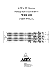
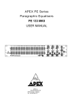
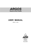
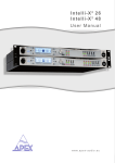
dBZ-48
User Manual
www.apex-audio.eu
APEX NV
Schoebroekstraat 62
3583 Beringen (Paal)
BELGIUM
Tel: + 32 (0)11 28 61 91
Fax: + 32 (0)11 25 56 38
e-mail: [email protected]
website: www.apex-audio.eu
Trademarks
The APEX trademark is owned by APEX N.V. All other brand, product and company names and any other registered names or trade marks
mentioned in this manual belong to their respective owners.
Disclaimer
APEX N.V. has taken all possible steps to ensure that the information given here is both correct and complete. In no event can APEX accept any
liability or responsibility for any loss or damage to the owner of the equipment, any third party, or any equipment which may result from use of
this manual or the equipment which it describes.
The information provided in this document may be modified at any time without prior warning. Specifications and appearance may differ from
those listed and illustrated. Any complaint against APEX N.V. shall be governed by the laws of Belgium.
dBZ-48
Stereo zone mixer
March 2010
Serial number of this product:
© 2010 APEX N.V. All rights reserved.
This manual may not be reproduced or transmitted, either in part
or as a whole, by any means, be they mechanical or electronic,
without the express written permission of APEX N.V.
Important safety instructions
Important safety instructions
CAUTION: to reduce the risk of electric shock, do not
remove cover (or back). No user-serviceable parts
inside. Refer servicing to qualified service personnel.
The lightning flash with arrowhead symbol,
within equilateral triangle, is intended to
alert the user to the presence of uninsulated
“dangerous voltage” within the product’s enclosure that
may be of sufficient magnitude to constitute a risk of
electric shock to persons.
The exclamation point within an equilateral
triangle is intended to alert the user to
the presence of important operating and
maintenance (servicing) instructions in the literature
accompanying the appliance.
Instructions
Before installing or operating the equipment, read all
safety instructions, warnings and operating instructions.
Heed all warnings. Follow all instructions. Keep all
safety, installing and operating instructions for future
reference.
Installing and operating location
Do not use this apparatus near water. Do not expose
this apparatus to drips or splashes. Do not place
any objects filled with liquids, such as vases, on the
apparatus.
Do not install near any heat sources such as radiators,
heat registers, stoves, or other apparatus (including
amplifiers) that produce heat. No naked flames, such
as lighted candles, should be placed on the apparatus.
The apparatus should be located close enough to the
AC outlet so that you can easily grasp the power cord
plug at any time.
The mains plug, the appliance coupler or the mains
switch is used as the disconnect device. Either device
shall remain readily operable when the apparatus is
installed or used.
Power source and grounding
This product should be operated only from the power
source indicated on the apparatus or in the operating
instructions. If you are not sure of the type of power
supply to your home, consult your product dealer or
local power company.
Do not defeat the safety purpose of the polarised or
grounding-type plug. A polarised plug has two blades
with one wider than the other. A grounding type plug
has two blades and a third grounding prong. The wide
blade or the third prong is provided for your safety. If
the provided plug does not fit into your outlet, consult an
electrician for replacement of the obsolete outlet.
Connect Class I construction apparatus to an AC outlet
with a protective grounding connection.
Do not overload wall outlets, extension cords or integral
convenience receptacles, as this can result in a risk of
fire or electric shock.
Protect the power cord from being walked on or pinched,
particularly at plugs, convenience receptacles and the
point where they exit form the apparatus.
Do not install the apparatus in a confined space such as
a book case or similar unit. Do not block any ventilation
openings.
Unplug this apparatus during lightning storms or when
unused for long periods of time.
Ensure that foreign objects and liquids cannot get into
the equipment.
Batteries (battery pack or batteries installed) should not
be exposed to excessive heat such as sunshine, fire or
the like. Never dispose of batteries in a fire as they may
explode and cause injury.
Install in accordance with the manufacturer’s instructions.
Only use attachments/accessories specified by the
manufacturer.
Use only with the cart, stand, tripod, bracket or
table specified by the manufacturer, or sold with the
apparatus.
When a cart is used, use caution when
moving the cart/apparatus combination to
avoid injury from tip over.
CAUTION: Danger of explosion if battery is incorrectly
replaced. Replace only with the same or equivalent
type.
Cleaning, maintenance and servicing
Unplug the apparatus from the wall outlet before
cleaning. Do not use liquid cleaners or aerosol cleaners.
Use a damp cloth for cleaning.
Do not attempt to service this product yourself, as
opening or removing covers may expose you to
dangerous voltage or other hazards. Refer all servicing
to qualified service personal.
Customer participation is important to minimize the
potential affects on the environment and human health
that can result from hazardous substances that may be
contained in this product.
Please, dispose of this product and its
packaging in accordance with local and
national disposal regulations including those
governing the recovery and recycling of waste electrical
and electronic equipment. Contact your local waste
administration, waste collection company or dealer.
Servicing is required when the apparatus has been
damaged in any way, such as power-supply cord or plug
damaged, liquid has been spilled or objects have fallen
into the apparatus, the apparatus has been exposed to
rain or moisture, does not operate normally or has been
dropped.
Intended use
The equipment may only be used for the purpose
described in the operation instructions. Never carry out
any work on the equipment other than as specified in
the operating manual.
Never push objects of any kind into this product through
openings, as they may touch dangerous voltage points
or short-cut parts, which could result in a fire or electric
shock.
Children should never use the apparatus without close
adult supervision.
WARNING: excessive sound pressure levels can cause
hearing loss.
Environmental precaution
Electrical and electronic equipment may contain hazardous substances for humans and their environment.
The “crossed out wheelie bin” symbol present
on the device and represented above is there
to remind one of the obligation of selective
collection of waste. This label is applied to
various products to indicate that the product is not to
be thrown away as unsorted municipal waste. At the
end of life, dispose of this product by returning it to the
point of sale or to your local municipal collection point
for recycling of electric and electronic devices.
Table of contents
Table of contents
Registration
Introduction
Product highlights
Foreword
7
Before you get started
9
9
9
9
9
9
About this manual
Inspection and unpacking
Operating environment
Power requirements
Installation
8
8
8
Front and rear panel description
Front panel
Rear panel
10
Overview
12
Wiring the unit
Overview
dBZ-48 Block diagram
12
12
13
Using the dBZ-48
14
Mono operation
14
Applications
19
Stereo music distribution
Bar/Pub with two music sources
15
16
Technical specifications
18
Electrical specifications
Mechanical specifications
18
19
Limited Warranty
20
10
11
Registration
Register your product
Please take the time to register your product on-line by typing the following URL in your browser:
http://productregistration.apex-audio.eu/
As well as registering the product on-line, please take the trouble to record the serial number of the unit in the
space provided on page 3 of the manual, and keep the manual in a safe place.
Introduction
Dear customer,
Thank you for buying the Apex dBZ-48. The dBZ-48 is a professional quality, 2-into-4 stereo zone mixer designed
to manage audio distribution in a variety of sound reinforcement applications including live PA and installed sound
systems.
Product highlights
• Two stereo input channels
• Four stereo output channels
• Electronically-balanced inputs
• High-quality, servo-balanced output stages, capable of driving long cables
• Stereo/mono switch on each input and output channel, with LED indication
• Mute button on each input and output channel, with LED indication
• LED signal metering for L & R on each input and output channel
• Rugged all–metal chassis
• Professional quality XLR connectors throughout
• 1U 19” rack-mounting unit
Foreword
The Apex dBZ-48 can be used in any situation where one
or two stereo audio signals need to be routed and mixed at
different levels to up to four destinations. The dBZ-48 will find
many applications as a zoner or distribution amplifier in both
live and installed audio situations.
When used as a zoner, any of the four outputs may receive
either of the two inputs at any level, or a mix of them. Mono/
stereo switching on both the inputs and the outputs makes
matching the unit to a variety of sources and speaker systems
simple.
An alternative installed sound application is to use the unit
as a distribution amplifier, to drive rows of loudspeakers in an
auditorium. It is common practice to drive speakers further from
the stage at a higher level, and the dBZ-48 makes setting up
such a system simple.
Before you get started
About this manual
Power requirements
Carefully read all instructions and warnings before operating
this appliance. Keep this manual in a safe place so that it can
be referred to when required.
BEFORE you connect any unit to the mains, please make
sure that your local AC supply is within the range of voltages
required by the unit.
Latest manual revision can be downloaded from:
http://www.apex-audio.be/manufacturing/support/downloads/
The dBZ-48 is designed to work from an AC supply between
100 V and 240 V, at a frequency between 50 and 60Hz. No AC
voltage selector is provided as the device automatically adjusts
to the incoming AC voltage.
Inspection and unpacking
This appliance has been carefully packed in the factory and the
packaging was designed to withstand rough handling. Should
the unit appear to have been damaged in transit, do not discard
any of the packing material and notify the carrier immediately
as they would be responsible.
Save all the packing materials for future use if you ever need to
ship the unit again.
Please check the list below against the contents of the
packaging. If any items are missing or damaged, contact the
Apex dealer or distributor where you purchased the unit.
• dBZ-48 unit
• IEC AC power cable with mains plug
• This manual
Precautions should be taken so that the appliance is properly
grounded at all times. This unit must be earthed.
Installation
If the unit is brought into a warm room from a cold environment,
internal condensation may occur. Wait an hour or two before
switching it on so that it can reach the ambient temperature.
Although this unit is intended for installation in a standard
19-inch rack it can nevertheless be used freestanding. If the
unit is installed in a flight-case or in an equipment rack, fix the
unit with all four screws through the front panel holes.
For normal use no extra support is needed, but in more
extreme conditions, such as on the road, we recommend the
unit is supported at the rear.
Allow at least 10 cm (4 inches) at the back, front and sides of
the unit for sufficient ventilation.
Operating environment
This appliance is designed to operate in moderate climates at
a temperature between 5 and 40°C (41 - 104°F) with relative
humidity no more than 60 %.
Should the unit be installed in an equipment rack, it is important
to ensure that the operating temperature inside the rack does
not exceed the upper limit. This could be the case where the
rack contains power amplifiers. A cooling fan may be necessary
in such installations.
Front and rear panel description
Front panel
4
7
12
15
13
6
5
14
10
1
16
11
3
2
8
17 18
9
Front panel
10
Input Controls:
Output Controls:
Front panel controls for IN A are described: those for IN B are
identical.
Front panel controls for OUT 1 are described: those for OUTS
2 to 4 are identical.
1 IN A LEVEL is a stereo control adjusting input stage gain,
with range from -∞ to +6 dB. The control is centre-detented at
unity gain (0 dB).
2 Pressing the latching MUTE button removes Input A’s signal
from all outputs.
3 Red LED indicates Input Mute [2] is active.
4 The Left and Right channels of the Input may be summed
with the MONO button. A 6 dB pad is inserted in mono mode to
maintain mono/stereo level compatibility.
5 Green LED indicates Input Mono [3] is active.
6 Three LEDs indicating signal level for each channel of the
stereo input: the green sig LED illuminates at -20 dBu; two
further yellow LEDs illuminate when the input level is +4 dBu
and +10 dBu respectively, with the LEVEL control set to zero.
The meters are post the input level control [1], and therefore
can be used when this is adjusted. However, they are pre the
mute button [2], and thus will continue to indicate the presence
of an input signal even when the mute is active. The meters
possess PPM-style ballistics (fast attack, slow decay).
7 A separate red Peak LED indicates that the signal level is
within 1 dB of clipping. The signal is monitored before the level
control [1] as well as at the metering point.
8 OUT 1 MIX A is a stereo control adjusting the level at which
Input A signal is fed to Output 1. The range is from -∞ to +6 dB.
The control is centre-detented at unity gain (0 dB).
9 OUT 1 MIX B has an identical function to [8] for Input B.
10 Pressing the latching MUTE button mutes Output 1
completely.
11 Red LED indicates Output Mute [10] is active.
12 The Left and Right channels of the Output may be summed
with the MONO button. As with the input mono function, a 6 dB
pad is inserted to maintain mono/stereo level compatibility.
13 Green LED indicates Output Mono [12] is active.
14 A set of meters is provided with characteristics identical to
those of the input meters [6]. The output metering point is post
both the Mix controls [8 & 9] and the Output Mute button [10].
15 A separate Peak LED indicates that the signal level is within
1 dB of clipping. The signal is monitored before the Mix controls
[8 & 9] as well as at the metering point.
Other front panel features:
16 A convenient set of scribble strips is provided for the user
to note the various zone locations. These can also accept
standard 6 mm or 9 mm width tape from Dymo ®, Brady ®,
Brother ®, etc. label printers.
17 The green Power LED illuminates when AC power is
applied to the unit. The dBZ-48’s power switch is on the unit’s
rear panel.
18 The dBZ-48 may be mounted in a standard 19” rack
housing. Please observe the guidance regarding ventilation.
Rear panel
2
3
6
1
4
5
Rear panel
All connections to the dBZ-48 are made via the rear panel.
3 IEC receptacle for AC mains.
Rear panel connections for IN A are described: those for IN B
are identical. Similarly, the details of the output connections are
identical for all four channels.
4 A POWER switch of the ‘rocker’ type applies power to the
unit.
1 Input A L & R. Inputs are on latching 3-pin female XLRs,
with separate connectors for left and right channels. The inputs
are electronically balanced. The pinout is as shown below:
PIN
1 GND
2 ‘Hot’ ( + )
3 ‘Cold’ ( - )
XLR (female)
5 Mains fuse holder. The fuse size is 20 x 5 mm, type T500mA
(slo-blo). Only replace a fuse with one of an identical size, type
and rating.
6 The unit’s serial number can be found on the rear of the
unit. Please record this number in the space provided on the
first page of this manual.
2 Output 1 L & R. Outputs are on 3-pin male XLRs, with
separate connectors for left and right channels. The outputs
are electronically balanced. The pinout is as shown below:
PIN
1 GND
2 ‘Hot’ ( + )
3 ‘Cold’ ( - )
XLR (male)
11
Overview
Wiring the unit
The use of twin-and-screen cable is recommended for both
inputs and outputs.
Inputs
Preferred wiring for both balanced and unbalanced sources is
illustrated below:
Balanced
groundlift jumpers on pcb
Outputs
Preferred wiring for both balanced and unbalanced destinations
is illustrated below:
Unbalanced
Balanced
Unbalanced
A ‘ground lift’ facility is available on the dBZ-48’s inputs, which
may be useful in resolving earth hum issues. Normally the input
XLR’s pin 1 is connected to ground, but this connection may be
broken by moving an internal pcb jumper.
Overview
The Apex dBZ-48 can be used in any situation where one or two
stereo audio signals need to be routed and mixed at different
levels to up to four destinations.
Each of the two inputs is provided with electronic balancing,
RFI filtering, mono/stereo switching, level control, a muting
circuit and LED metering. The A & B inputs are each split to the
four output channels, and summed separately in each.
The level of each input signal fed to each output channel may be
individually set. Again, mono/stereo switching, muting and LED
metering are available for each output. The servo-balanced
12
output stage design results in a very low output impedance,
making it possible to drive long balanced lines (e.g., from a
FOH mix position to stage amp racks).
dBZ-48 Block diagram
13
Using the dBZ-48
Using the dBZ-48
Operation of the dBZ-48’s input and output sections is entirely
straightforward, and requires only correct adjustment of the
respective level controls.
Start with all the front panel rotary controls fully anticlockwise.
Connect the stereo input source(s) to IN A and IN B and the
stereo outputs to their respective amplifiers (or other signal
processing) as appropriate. With the programme material
present, rotate the input level controls until the second (+6dB)
LEDs flash on the loudest peaks, but so that the red peak LEDs
do not illuminate. Then rotate the output level controls for each
output channel in turn to obtain a similar display on each pair of
output LED meters.
Mono operation
The MONO buttons on the input channels should be used if the
input in question is being fed from a mono source. In this case,
the input signal may be applied to either the L or R input.
If any of the outputs are to be used in mono (e.g. with the
dBZ-48 in use as a zoner, it may not be practical for some
room areas to support effective stereo operation), the output
channel MONO buttons may be used to make an L+R sum of
the stereo input signals available at both L and R outputs of a
channel. This does not compromise the other output channels
being used as stereo, of course.
14
Applications
Stereo music distribution
In this example, the dBZ-48 is used to feed 4 zones or areas
of a building, typically an office, retail store, restaurant, coffee
shop, or similar. The requirement is to have stereo music
playing throughout the building, but at different sound levels in
the various zones. The dBZ-48 is excellent for this application,
as it provides simple central control of the level in each zone,
as well as overall “master” level control.
The music source is connected to In A, and the four outputs
to the stereo power amplifiers driving the speaker systems in
each zone. If any zone(s) is more suitable for mono audio (see
page 14), Mono may be selected on that output only without
affecting any other zones.
Out 1 Mix A, Out 2 Mix A, Out 3 Mix A and Out 4 Mix A set the
individual sound level in each zone, while In A Level acts as an
overall level control for the whole system.
Note that In B is not used in this application, and all the B controls
should be left at minimum.
15
Bar/Pub with two music sources
Many venues have large-screen TVs installed in several areas,
but often wish to only use those in certain areas, and play
background music elsewhere. The arrangement shown in the
first example above can be simply extended to accommodate
this requirement.
In this example, the TV tuner or satellite receiver’s audio output
is connected to In B and the background music source to In A.
Each of the four outputs feeds one of the venue’s areas via a
power amplifier. As in the first example, if any zone(s) is more
suited to mono operation, that output’s Mono button may be
pressed.
The venue staff may select whether each of the areas receives
TV sound or the background music, and set the level in each
zone independently. In A is the “master” level control for the
music and In B the “master” level control for the TV sound. The
Mix A or Mix B level controls in each output section are used
to determine whether that zone plays music or the TV sound,
and at what level. If wished, a mix of the two sources (typically
with the background music kept low) may be used in one or
more zones.
16
17
Technical specifications
Electrical specifications
Balanced line level input
Connectors
Impedance
Max. input level
CMRR
3-pin XLR
> 10 k ohm, balanced
+21 dBu, balanced, 1 % THD+N
> 60 dB, 1 kHz
Balanced line level output
Connectors
Impedance
Max. output level
3-pin XLR
< 50 ohm, balanced
+ 26 dBu into 600 ohm, balanced, 1 % THD+N
Audio performance (unity gain, all settings flat)
Frequency response
THD+N
Dynamic range
Crosstalk
20 Hz - 20 kHz, +/- 0.5 dB
less than 0,005 %, +4 dBu, 20 Hz - 20 kHz, 22 kHz BW
> 110 dB, ref +26 dBu, 22 kHz BW, unweighted
-80 dB, 20 Hz - 20 kHz, +4 dBu, channel-to-channel
AC power requirements
Voltage
Power consumption
Auto-detect 100 - 240 V - 50/60 Hz
30 VA
Environment
Operating
Temperature
Relative humidity
5° to 40° C
up to 60 %
Storage
Temperature
18
-20° to 60° C
Mechanical specifications
Weight
Dimensions
Unit
Package
Width
Height
Depth
482 mm (19-inch)
44 mm (1U)
183 mm
Width
Height
Depth
530 mm
115 mm
275 mm
Unit (Nett)
2,5 kg
Unit + Package (Shipping)
3,7 kg
In the interest of product development, Apex reserve the right to modify or improve specifications of this product at any time,
without prior notice and without any obligation to change or update equipment already delivered.
19
Limited warranty
Limited warranty
Apex N.V. (“Apex”) warrants you, the original purchaser, or any party that purchases the device from you,
that its products are free from defects in material and workmanship under normal use for a period of two
(2) years from the date of original purchase. The date of purchase is the date which appears on the first
invoice or any other proof of purchase provided by an Apex approved dealer.
Subject to the conditions and limitations set forth below, Apex will, at its discretion, either repair or replace
any part of its products that prove to be defective, provided that the product is returned with proof of
purchase, shipping prepaid, to an authorised Apex approved service facility.
Warranty cover of any repairs will only extend to the end of the original warranty period.
We will be happy to provide you with a list of authorised dealers to whom you can return the defective unit
or who will give you a returns note to enable you to send the unit to the factory.
Service turn-around time will be as fast as reasonably possible. If you are not satisfied with the repair,
contact Apex.
Exclusions and limitations
This limited warranty covers only repair or replacement for defective products manufactured by Apex.
Apex is not liable for, and does not cover under warranty, any loss of data or any costs associated with
determining the source of system problems or removing, servicing or installing Apex products. This
warranty excludes 3rd party software, connected equipment or stored data. Apex does not warrant
that the operation of the product will be uninterrupted or error-free. In the event of a claim, Apex’s sole
obligation shall be replacement of the hardware.
This limited warranty does not cover:
(1) any damage to this product that results from improper installation, accident, abuse,
misuse, natural disaster, insufficient or excessive electrical supply, abnormal mechanical or
environmental conditions or other external causes;
(2) any damage caused by operating the product outside the permitted or intended uses described
by Apex;
(3) any damage caused by any unauthorized disassembly, repair, or modification;
(4) consumable parts, such as batteries;
(5) any cosmetic damage.
Apex is not liable for consequential damages.
This limited warranty also does not apply to any product on which the original identification information
(including serial number) has been altered, obliterated or removed or any product that has not been
handled or packaged correctly.
Warranty services will be furnished only if the product is accompanied by a copy of the original retail
dealer’s invoice.
Warranty claims other than those indicated above are expressly excluded.
20
www.apex-audio.eu
[email protected]
Copyright
© 2010 APEX N.V.
All rights reserved. This manual may not be reproduced or transmitted, either in part or as a whole, by any means,
be they mechanical or electronic, without the express written permission of APEX N.V.
Please recycle