1
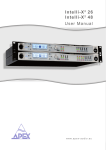
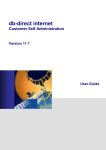
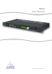
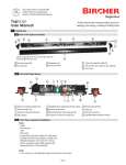
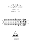
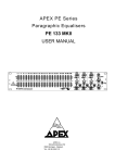
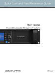
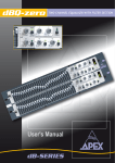
dBDI-2
User Manual
www.apex-audio.eu
APEX NV
Schoebroekstraat 62
3583 Beringen (Paal)
BELGIUM
Tel: + 32 (0)11 28 61 91
Fax: + 32 (0)11 25 56 38
e-mail: [email protected]
website: www.apex-audio.eu
Trademarks
The APEX trademark is owned by APEX N.V. All other brand, product and
company names and any other registered names or trade marks mentioned
in this manual belong to their respective owners.
Disclaimer
APEX N.V. has taken all possible steps to ensure that the information given
here is both correct and complete. In no event can APEX accept any liability
or responsibility for any loss or damage to the owner of the equipment, any
third party, or any equipment which may result from use of this manual or
the equipment which it describes.
The information provided in this document may be modified at any
time without prior warning. Specifications and appearance may differ
from those listed and illustrated. Any complaint against APEX N.V.
shall be governed by the laws of Belgium.
dBDI-2
Dual active Direct Injection box
November 2009
Serial number of this product:
© 2009 APEX N.V. All rights reserved.
This manual may not be reproduced or transmitted, either in part or as a
whole, by any means, be they mechanical or electronic, without the express
written permission of APEX N.V.
Intended use
The equipment may only be used for the purpose
described in the operation instructions. Never carry out
any work on the equipment other than as specified in
the operating manual.
Environmental precaution
Electrical and electronic equipment may
contain hazardous substances for humans
and their environment.
The “crossed out wheelie bin” symbol
present on the device and represented
above is there to remind one of the obligation of
selective collection of waste. This label is applied to
various products to indicate that the product is not to be
thrown away as unsorted municipal waste.
At the end of life, dispose of this product by returning it
to the point of sale or to your local municipal collection
point for recycling of electric and electronic devices.
Customer participation is important to minimize the
potential affects on the environment and human health
that can result from hazardous substances that may be
contained in this product.
Please dispose of this product and its packaging in
accordance with local and national disposal regulations,
including those governing the recovery and recycling of
waste electrical and electronic equipment. Contact your
local waste administration, waste collection company or
dealer.
Register your product
Please take the time to register your product on-line by
typing the following URL in your browser:
http://productregistration.apex-audio.eu/
As well as registering the product on-line, please take
the trouble to record the serial number of the unit in the
space provided on page 3 of the manual, and keep the
manual in a safe place.
Introduction
Product highlights
•
•
•
•
•
•
•
•
•
•
•
•
•
•
•
•
Two independent channels, ideal for use with stereo keyboards,
DJ consoles, etc.
Low noise and distortion audio design with excellent headroom
Low inter-channel crosstalk
High quality output transformers; providing excellent
output balance and true galvanic isolation
Very low output impedance allows use of long cable runs
XLR, ¼” jack and phone (RCA) inputs
Ground lift switch per channel
3-position pad switch per channel permits matching of all
signal levels
Mono mix mode - channels are summed, mix feeds both outputs
Can be powered from mixing console (via phantom power)
or optional external AC adapter
Speaker interface allows amplifier “sound” to be retained
Power LED per channel
Rugged all–metal chassis
Professional quality connectors
Optional rack kit available - mounts two units in 19” rack
Kensington security lock
Thank you for buying the Apex dBDI-2.
The dBDI-2 is a professional quality, two channel,
active direct injection (DI) box, which provides
a simple method of connecting analogue audio
signals of all types to professional amplification or
recording systems.
The dBDI-2 has a number of unique features which
distinguish it from other active DI boxes; even if
you are familiar with this type of equipment, you
are recommended to read this manual carefully to
obtain the maximum benefit from the dBDI-2.
Overview
Overview
The Apex dBDI-2 can be used in any live performance or
recording situation where you need to interface electric
or electronic musical instruments, or “consumer” audio
equipment with professional or broadcast equipment.
Examples of electric or electronic musical equipment are
electric guitars, synthesisers, samplers and electronic
keyboards of all types. Consumer audio equipment might
include domestic CD & DVD players, computer sound
cards, MP3 players and DJ consoles. By “professional
or broadcast equipment” we mean touring or fixed venue
PA systems, recording studio mixing consoles, TV or
radio OB trucks, and so on.
Using the dBDI-2 gives you two main advantages:
• Most of the audio sources mentioned above are
low-level, high-impedance or unbalanced, and often
all three! These make them unsuitable for direct
connection to professional equipment. Putting a
dBDI-2 box in circuit means that they are correctly
matched to the balanced inputs such equipment
invariably has.
•
The dBDI-2 additionally provides complete
electrical isolation between the audio sources and
the professional equipment, thereby removing at
a stroke all the usual causes of hums and buzzes
when different audio systems are interconnected.
In addition, the dBDI-2’s dual-channel architecture and its
unique sum mode switch opens up further applications,
such as acting as a splitter. This would allow a sound
source to be sent to two separate audio systems – such
as FOH and monitor desks, or PA system and recording
truck – with full signal isolation between all three
connected systems.
Block diagram
The diagram on the left shows a
simplified block diagram of the
dBDI-2.
The signal path is identical for the
two channels.
Front and rear panel description
9
5
13
17 14
6
10
FRONT PANEL
11
1
19
7
16
3
4
18
8
2
12
15
REAR PANEL
ITEM
CHANNEL A
Unbalanced inputs (XLR)
1
Unbalanced inputs (1/4” mono jack)
3
Unbalanced input link connector (1/4” mono jack)
5
Unbalanced input (phono)
7
Ground lift switch
9
Input pad switch
11
Power LED
13
Balanced outputs (XLR)
15
Dual/Sum mode switch
17
Ext. DC power input
18
Kensington® security lock
19
CHANNEL B
2
4
6
8
10
12
14
16
Features and functions
Power requirements
Choice of inputs
This dBDI-2 can operate either from phantom 48V power
supplied by a mixing console (or other equipment)
connected to the unit’s output, or an external AC mains
adapter rated at 12 V DC.
Each channel has completely independent internal power
circuitry and draws phantom power from its respective
output connector.
The three inputs – XLR3F, ¼” jack and phono (RCA) – are
all in parallel and any one may be used, depending on
connector convenience. Do not connect audio sources to
more than one (per channel) simultaneously. The inputs
are all unbalanced and have the same impedance and
sensitivity. Note that pins 1 and 3 of the XLR are shorted,
and thus a balanced signal connected to it will become
unbalanced.
Optional universal AC adapter
LINK connector
A universal, useable worldwide, AC adapter delivering
12 Vdc may be ordered separately from the dBDI-2.
The ¼” LINK connector is in parallel with all three inputs.
It lets you use your existing instrument amplification
(e.g., a guitar amp) while sending the instrument signal
to the mixing console (or other equipment) that the
dBDI-2’s output is feeding. You can either insert the
dBDI-2 between your instrument and the amp’s input,
or, if your amp top and speaker cabinet are separate,
between the amp’s output and the speaker. Examples
are given in the “Applications” section.
Order code: APX-0ADAPTER-12V
No damage will result to the unit if both phantom
power and an external DC supply are connected
simultaneously.
10
Output
The output of each channel is on an XLR3M connector;
the output is balanced and isolated by a transformer,
providing a very low source impedance. This makes
the dBDI-2 suitable for driving very long cable runs
without significant signal loss. Another advantage of
the transformer is that it provides full electrical isolation
between the equipment connected to the DI box’s inputs
and the console or recording device at the output. This
minimises the likelihood of hums and buzzes.
Always use XLR-XLR cables (usually referred to as “mic
cables”) with all 3 pins connected at both ends.
Pad Switch
The Pad switch lets you set the unit’s input sensitivity to
suit the various signal levels that different items of audio
equipment can produce.
The highest sensitivity – i.e., that suitable for low-level
sources such as some types of instrument pickups – is
obtained with the switch in the 0dB position. Sources
such as “consumer” CD players and laptops are more
likely to require a setting of -20dB. When using highlevel sources such as guitar amplifier outputs, always
set the Pad switch to -40dB.
If in doubt about the output level of the equipment you are
connecting to the dBDI-2’s input, always set the switch
to -40dB initially, and check whether the signal being
received at the mixing console (or other equipment) is
sufficient; if not, increase the sensitivity by setting the
pad to -20dB, and check again. The switch should be set
so that no clipping is evident at the mixing console (or
other equipment) on signal peaks.
11
Ground Lift switch
Hum loops can occur in interconnected audio equipment
when different grounding (earthing) practices are
employed; equipment or systems which operate cleanly
in isolation generate a system-wide hum when connected
together.
The problem can usually be resolved by separating the
“screen” connection of the DI box’s input signal and the
screen (pin 1) of the output XLR. This is the purpose of
the Ground Lift switch. Set Ground Lift to GND by default,
only “lift” the ground to resolve a hum problem.
Dual/Sum switch
With the Dual/Sum switch set to Dual, the dBDI-2’s two
channels function independently, as if you were using
two completely separate DI boxes. This is ideal for
stereo sources, such as most keyboards, samplers, DJ
consoles, etc.
Setting the switch to Sum connects the two channels
together internally.
12
This lets you use the DI box in several extra ways:
• You can use the dBDI-2 as a signal splitter, whereby
the input signal is sent to two completely separate
destinations, with full isolation between everything.
You’re limited to a mono input, though.
• If you’re running out of channels on the FOH mixer,
you can use the dBDI-2 to mix two mono signals
together to a single output.
• If you’re using two keyboards, you can use two
dBDI-2s to reduce your stage feed to just one stereo
pair. The FOH engineer will love you !
Important
When the Dual/Sum switch is set to Sum, it is
important to ensure that the position of the ground lift
switches on both channels is identical. This ensures
a common ground potential between the channels,
resulting in improved performance.
Stacking several dBDI-2’s
Security Lock
Multiple dBDI-2s may be stacked vertically to save
space on stage. The rubber side cheeks are specially
designed to facilitate this, with the protrusions forming
the “feet” slotting into the grooves on the top of the cheek
of another unit, as shown. Several units may be stacked
in this way, forming a stable assembly.
The rear of the dBDI-2 unit is equipped with a
standard Kensington® computer-style security
lock anchor point. This can be used with a
Kensington® MicroSaver Security cable (available
from most computer suppliers) to secure the DI box to a
convenient immovable object. If units are rack-mounted,
the cable anchor point can be a point within the racks
internal structure, which will prevent the units from being
removed even if the rack mount assembly is removed
from the rack.
13
Optional Rack Mount Panel
Individual dBDI-2 units are intended to be used freestanding, however two dBDI-2 units may be mounted
side-by-side in the optional 19” rack mount adapter .
The rack adapter is a standard 19” 1U panel with apertures
for two dBDI-2 units, and four XLR3M connectors (two
per unit) already fitted. The XLRs come with flying leads
terminated in XLR3M connectors. Once installed in a
rack, the DI box rear panel output connectors will no
longer be accessible, so the connector/cable assembly
re-situates them on the rack panel.
Fitting the dBDI-2’s in the rack adaptor
1.Remove the two rubber side cheeks from one of the
dBDI-2s. This is done by undoing the four M4 hex socket
screws securing the cheeks to the front panel and the
four similar screws securing them to the rear panel
(screws are visible within the cheek rubbers).
Retain the screws.
14
2.Fit the front panel of the DI box into the one of
apertures in the rack panel (make sure it’s the right way
up!). Use four of the eight screws removed in Step 1 to
attach the unit to the panel, inserting the screws through
the four holes in the panel. Fit the four remaining screws
removed in Step 1 to the rear of the unit.
3.Repeat Steps 1 & 2 for the second DI box.
4.Plug the four flying XLR cables into the four DI box
outputs on the rear of the boxes. Take care not to cross
any leads.
5.If external PSUs are being used, plug them in as well.
Cable ties attaching the DC power leads to one or more
of the flying output cables may be helpful in providing
some additional strain relief.
6.The rack panel is now ready to mount in a rack, flight
case or other housing. (See illustration on next page.)
15
Applications
The following pages illustrate some typical applications for the dBDI-2:
1
Obtaining a recording or FOH feed from an electric guitar
Plug the guitar into Channel A’s ¼” jack socket with a standard guitar lead. If using FX
pedals, take the output from the last pedal instead if you want the effects to be sent to
the mixing console as well. Use another to connect Channel A’s LINK connector to the
usual input of your guitar amplifier. Connect the output of Channel A (at the rear of the
dBDI-2) to an input channel of the mixing console with an XLR cable. (Depending on the
situation, this may be a direct connection, or via a stage box, or a studio mic input panel.)
Set the controls on your guitar and amplifier in the usual way, and set the Pad switch to
either -20dB or 0dB while adjusting the input gain on the mixing console channel. The
aim is to ensure that no clipping occurs at the mixing console with the guitar’s volume
control at maximum and you’re playing the loudest passages. You can set the amplifier
controls as you want, as they do not affect the signal being sent to the mixing console.
16
17
2
Obtaining a recording or FOH feed from a stereo keyboard
Many keyboards have stereo outputs, so you can use the two channels of a single dBDI-2 to
interface a keyboard (or sampler, etc.) to a mixing console in a stage or recording situation.
Connect the L and R outputs of the keyboard (usually on 1/4” jacks) to the 1/4” jack inputs of
the two channels of the DI box. Then connect the two outputs to the mixing console, directly
or otherwise, using XLR cables. The most likely setting for the Pad switch in this setup will
be -20dB. Foldback for the keyboards player can be derived from the mixing console in a
studio situation.
18
19
3
Obtaining a recording or FOH feed from the output of
a guitar amplifier
Many guitarists wish to retain their “amp sound” during recording or when playing with
large PA systems, particularly when using valve/tube amps. The dBDI-2’s ability to
be inserted in circuit between the output of the guitar amp and the speaker cabinet
(assuming you’re not using a combo amp) lets you do this. Use a normal speaker cable
to connect between the amp’s output and the ¼” jack input of one channel, and run
another from the LINK output of the same channel to the speaker cabinet.
The rear XLR output of the channel in use goes to the mixing console in the normal way.
Always set the Pad switch to -40dB when using this configuration. The volume and tone
of the guitar sound sent to the console is now determined by the amplifier settings, and
will include amplifier-imparted characteristics such as valve/tube and output transformer
saturation.
20
21
4
Hooking up a laptop to a DJ mixer
Attempting to interface computer sound cards to an audio system often generates hum, buzzes and
other extraneous digital noises due to the poor design of computer power supplies. Laptops are
particularly bad in this respect. The dBDI-2 can be used to provide electrical isolation between the
computer and the audio system, which will resolve all noise problems in most cases. Use a computer
audio cable with a 3.5mm 3-pole jack at one end and two phono (RCA) plugs at the other. Plug the
jack end into the computer’s sound card output (use the “line out” connector rather than a “headphone”
output if one is available) and plug the other end into the phono sockets of the dBDI-2’s two channels.
If the DJ console has balanced XLR inputs available, use two XLR cables to connect the DI box
outputs to these. If only unbalanced inputs on ¼” jacks (or phonos) are available, either use two
XLR-to-1/4” mono jack (or phono) cables, or standard XLR cables with XLR-to-jack (or XLR-to-phono)
adapters. In either case, the output of the DI box will become unbalanced, and thus long cable lengths
should be avoided. Satisfactory results should be obtainable with the Pad switch set to -20dB.
Note in this application that most DJ consoles do not provide phantom power at any inputs, even if
they are equipped with XLRs. Thus it will generally be necessary to power the dBDI-2 from an external
AC adapter, as shown.
22
L
L
R
R
23
5
Using the dBI-2 as a line-level splitter
This example is an extension of Example 1. The guitarist is using the dBDI-2 to send
the (raw) guitar signal to the FOH mixing console as before, but by setting the Dual/Sum
switch to Sum, a second output, completely independent of and isolated from the first, is
available at Output B, to feed the monitor mixing console.
This configuration can also be used to generate an isolated instrument feed for live
recording or broadcast purposes.
When the Dual/Sum switch is set to Sum, it is important to ensure that the position of
the ground lift switches on both channels are identical. This ensures a common ground
potential between the channels, resulting in improved performance.
24
25
6
Using two dBDI-2s with stereo keyboards to reduce the number
of mixer channels required
This example shows a convenient way of reducing the number of channels required at
the mixing console from four to two when using two stereo keyboards on stage. The two
keyboards are connected to the two dBDI-2s as follows:
Keyboard 1 L
Keyboard 1 R
Keyboard 2 L
Keyboard 2 R
to
to
to
to
dBDI-2 #1 Input A
dBDI-2 #2 Input A
dBDI-2 #1 Input B
dBDI-2 #2 Input B
The stereo output to the mixing console is taken from Output A of dBDI-2 #1 (L) and
Output A of dBDI-2 #2 (R). The output levels of the two keyboards should be matched
during sound check to avoid the FOH engineer having to adjust his input gains when the
player switches from one keyboard to another.
26
When the Dual/Sum switch is set to Sum, it is important to ensure that the position of
the ground lift switches on both channels are identical. This ensures a common ground
potential between the channels, resulting in improved performance.
27
Technical specifications
Electrical specifications
28
Unbalanced input
Connectors:
1/4” TRS jack (Tip = hot, Ring = Sleeve = ground)
3-pin XLR (Pin 2 = hot, Pin 1 = Pin 2 = ground)
RCA (Phono) (Tip = hot, Sleeve = ground)
Parallel output 1/4” TRS
Attenuator:
Impedance:
Max input level:
0 dB
1 M-ohm
+9 dBu
Transformer balanced output
Connector:
Impedance:
Max output level:
3-pin XLR (Pin 1 = ground, Pin 2 = hot, Pin 3 = cold)
< 50-ohm
+9dBu into 600 ohm load
Audio performance
Frequency response:
Signal to noise ratio (S/N):
Total Harmonic Distortion + Noise (THD+N): Channel separation (Crosstalk):
20 Hz - 20 kHz, +0/-0.5 dB into >1k5 load
110 dB, ref. 0 dBu, 22 kHz BW, unity gain, unweighted
less than 0,005%, 0 dBu, 30Hz- 20 kHz, unity gain, 22 kHz BW
-75 dB, 20 Hz - 20 kHz, 0 dBu
Phantom power requirements
Voltage:
Current drain: +48 Vdc
less than 10 mA per channel
External AC adapter requirements
Voltage:
Current drain:
+9Vdc to +12 Vdc
less than 18 mA total
20dB
>40k-ohm
+29 dBu
40 dB
>40 k-ohm
+33 dBu
Mechanical specifications
Netto weight: 870 g
Packaging width: depth: height: 200 mm
120 mm
60 mm
Shipping
weight:
1 kg
In the interest of product development, Apex reserve the right to modify or improve specifications of this product at any time, without prior notice
and without any obligation to change or update equipment already delivered.
29
Limited warranty
Limited warranty
Apex N.V. (“Apex”) warrants you, the original purchaser, or any party that
purchases the device from you, that its products are free from defects in
material and workmanship under normal use for a period of two (2) years
from the date of original purchase. The date of purchase is the date which
appears on the first invoice or any other proof of purchase provided by an
Apex approved dealer.
Subject to the conditions and limitations set forth below, Apex will, at its
discretion, either repair or replace any part of its products that prove to
be defective, provided that the product is returned with proof of purchase,
shipping prepaid, to an authorised Apex approved service facility.
Warranty cover of any repairs will only extend to the end of the original
warranty period.
We will be happy to provide you with a list of authorised dealers to whom
you can return the defective unit or who will give you a returns note to enable
you to send the unit to the factory.
Service turn-around time will be as fast as reasonably possible. If you are
not satisfied with the repair, contact Apex.
Exclusions and limitations
This limited warranty covers only repair or replacement for defective
products manufactured by Apex. Apex is not liable for, and does not cover
under warranty, any loss of data or any costs associated with determining
the source of system problems or removing, servicing or installing Apex
30
products. This warranty excludes 3rd party software, connected equipment
or stored data. Apex does not warrant that the operation of the product will be
uninterrupted or error-free. In the event of a claim, Apex’s sole obligation shall
be replacement of the hardware.
This limited warranty does not cover:
(1) any damage to this product that results from improper installation,
accident, abuse, misuse, natural disaster, insufficient or excessive
electrical supply, abnormal mechanical or environmental conditions or
other external causes;
(2) any damage caused by operating the product outside the permitted or
intended uses described by Apex;
(3) any damage caused by any unauthorized disassembly, repair, or
modification;
(4) consumable parts, such as batteries;
(5) any cosmetic damage.
Apex is not liable for consequential damages.
This limited warranty also does not apply to any product on which the
original identification information (including serial number) has been altered,
obliterated or removed or any product that has not been handled or packaged
correctly.
Warranty services will be furnished only if the product is accompanied by a
copy of the original retail dealer’s invoice.
Warranty claims other than those indicated above are expressly excluded.
www.apex-audio.eu
[email protected]
Copyright
© 2009 APEX N.V.
All rights reserved. This manual may not be reproduced or transmitted, either in part or as a whole,
by any means, be they mechanical or electronic, without the express written permission of APEX N.V.
Please recycle