1
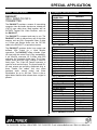
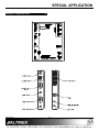
SPECIAL APPLICATION
MANUAL PART NUMBER: 400-0198-002
DA1930CT
VGA + AUDIO TO CAT-5
TRANSMITTER
USER’S GUIDE
SPECIAL APPLICATION
TABLE OF CONTENTS
Page
PRECAUTIONS / SAFETY WARNINGS ..............2
GENERAL..........................................................2
INSTALLATION .................................................2
CLEANING.........................................................2
FCC / CE NOTICE..............................................2
ABOUT YOUR DA1930CT ...................................3
TECHNICAL SPECIFICATIONS...........................3
PRODUCT DESCRIPTION ..................................4
APPLICATION DIAGRAM ....................................5
DIAGRAM 1: TYPICAL CONFIGURATION ........5
DIAGRAM 2 RJ-45 PINOUT ..............................6
DIAGRAM 3 INTERNAL VIEW ..........................7
INSTALLING YOUR DA1930CT...........................8
OPERATION ........................................................8
VIDEO EQUALIZATION .....................................8
AUDIO GAIN ......................................................8
TROUBLESHOOTING GUIDE .............................9
LED IS NOT RED ...............................................9
LED IS NOT GREEN ..........................................9
NO SOUND........................................................9
NO REMOTE IMAGE .........................................9
REMOTE IMAGE QUALITY IS POOR ..............10
ALTINEX POLICY ..............................................10
LIMITED WARRANTY/RETURN POLICY ........10
CONTACT INFORMATION ..............................10
400-0198-002
1
SPECIAL APPLICATION
PRECAUTIONS / SAFETY WARNINGS
•
1
Please read this manual carefully before using your
DA1930CT. Keep this manual handy for future
reference. These safety instructions are to ensure
the long life of your DA1930CT and to prevent fire
and shock hazard. Please read them carefully and
heed all warnings.
1.1 GENERAL
•
Qualified ALTINEX service personnel, or their
authorized representatives must perform all
service.
1.2 INSTALLATION
•
•
•
•
To prevent fire or shock, do not expose this unit
to rain or moisture. Do not place the DA1930CT
in direct sunlight, near heaters or heat radiating
appliances, or near any liquid. Exposure to
direct sunlight, smoke, or steam can harm
internal components.
Handle the DA1930CT carefully. Dropping or
jarring can damage the unit.
Do not pull the cables that are attached to the
DA1930CT.
1.3 CLEANING
•
Clean only with a dry cloth. Never use strong
detergents or solvents, such as alcohol or
thinner. Do not use a wet cloth or water to clean
the unit. Do not open the unit to clean.
1.4 FCC / CE NOTICE
•
This device complies with part 15 of the FCC
Rules. Operation is subject to the following two
conditions: (1) This device may not cause
harmful interference, and (2) this device must
accept any interference received, including
interference that may cause undesired
operation.
400-0198-002
2
This equipment has been tested and found to
comply with the limits for a Class A digital
device, pursuant to Part 15 of the FCC Rules.
These limits are designed to provide reasonable
protection against harmful interference when the
equipment is operated in a commercial
environment. This equipment generates, uses,
and can radiate radio frequency energy and, if
not installed and used in accordance with the
instruction manual, may cause harmful
interference to radio communications. Operation
of this equipment in a residential area is likely to
cause harmful interference in which case the
user will be required to correct the interference
at his own expense.
Any changes or modifications to the unit not
expressly approved by ALTINEX, Inc. could void
the user’s authority to operate the equipment.
SPECIAL APPLICATION
ABOUT YOUR DA1930CT
2
TECHNICAL SPECIFICATIONS
DA1930CT
VGA + AUDIO TO CAT-5
TRANSMITTER
FEATURES/
DESCRIPTION
GENERAL
Inputs Video
YPbPr (RGBHV)
S Video
Composite
Input Stereo Audio
Outputs
Local Monitor
Local Audio
Main Output
Compatibility
The DA1930CT provides a means of transmitting
computer video and audio signals over twisted pair
(CAT-5) type cable when used together with an
ALTINEX Twisted Pair Video Receiver, such as
the DA1931CT.
The DA1930CT is compact and easy to use. The
DA1930CT is able to transmit any one of the video
sources, such as VGA, Component Video, S-video
or C-Video and Stereo Audio over the CAT-5/6
cable to the DA1931CT or equivalent receiver.
DA1930CT
15 PIN HD
4 PIN MINI DIN
RCA Jack
3.5mm Stereo Jack
15 PIN HD
3.5mm Stereo Jack
RJ-45 Female (3)
VGA thru UXGA, Stereo Audio
Table 1. DA1930CT General
MECHANICAL
Material
Finish
Top Panel
Height (inches)
Width (inches)
Depth (inches)
Weight (pounds)
Ship Weight (pounds)
T° Operating
T° Maximum
Humidity
MTBF (calculations)
The DA1930CT provides Audio Loop output and
buffered VGA Output for a Local Monitor
connection. The DA1930CT offers a female 15-pin
HD input with the native Plug & Play compatibility,
4 pin Mini-Din connector for S-Video and RCA
connector for Composite Video Input. The 3.5mm
Stereo Audio Jack with Loop Through is used for
Audio Input. The 15-pin HD Female connector is
used for local monitor output. The three female RJ45 main outputs are providing distributed drive to
three Twisted Pair cables. Unit also offers
hardware audio volume control and Video
Equalization for up to 400 feet. There is also a
signal detect feature which shows when a signal is
present.
DA1930CT
0.1” Al
ALTINEX Grey
Lexan Overlay
5.28in (134mm)
4.29in (109mm)
0.98in (25mm)
1.40lb (0.63kg)
2.1lbs (0.95kg)
10°C-35°C
50°C
90% non-condensing
40,000 hrs
Table 2. DA1930CT Mechanical
ELECTRICAL
Input Video Signal
Analog Signal Level
Impedance
Input Sync Signal
HSYNC/VSYNC
Impedance
Input Audio Signal
Impedance
Max Level
Output Signals
Local Monitor RGBHV Impd.
Local Audio
Power
External Adapter (included)
Table 3. DA1930CT Electrical
400-0198-002
3
3
DA1930CT
1.2 Vp-p max
75 Ohms
TTL
10 kOhms
10 kOhms
1 Vp-p
75 Ohms
Direct Thru from Input
9V DC, 1A
SPECIAL APPLICATION
PRODUCT DESCRIPTION
400-0198-002
4
4
SPECIAL APPLICATION
APPLICATION DIAGRAM
5
DIAGRAM 1: TYPICAL CONFIGURATION
400-0198-002
5
SPECIAL APPLICATION
DIAGRAM 2 RJ-45 PINOUT
TOP
1
1
8
FRONT
Pin Number
RJ-45 Output Signals
1
Orange/White
2
Orange
3
Green/White
4
Blue
5
Blue/White
6
Green
7
Brown/White
8
Brown
Table 1
Standard 568B Wiring Color Code
400-0198-002
6
8
SPECIAL APPLICATION
DIAGRAM 3 INTERNAL VIEW
VGA + AUDIO TO CAT-5 TRANSMITTER
POWER
2.5mm
9V, 1A
SIGNAL
DETECT
POWER
SUPPLY
POWER
INPUT
RCA
C-VIDEO
INPUT
4PIN MINI
DIN
S-VIDEO
PNP
CHROMA
LUMA
PAIR 1
PAIR 2
H/W
VER
PAIR 3
SYNC
PROCESSING
GAIN
OUTPUT3
PORT2
RJ 45
CAT5
PAIR 4
HOR
BLUE
PAIR 1
RED
PAIR 2
INPUT
15PIN VGA
RGBHV/
Y Pb Pr
PAIR 3
GREEN
OUTPUT2
PORT1
RJ 45
CAT5
RIGHT
INPUT
3.5mm
STEREO
AUDIO
H/W
AUDIO
MODULATION
PAIR 4
GAIN
LEFT
PAIR 1
CLOCK
GENERATOR
PAIR 2
PAIR 3
OUTPUT1
PORT2
RJ 45
CAT5
PAIR 4
VER
HOR
GREEN
LOCAL
OUTPUT
15PIN
VGA
RED
BLUE
LEFT
RIGHT
400-0198-002
7
LOCAL
OUTPUT
3.5mm
STEREO
AUDIO
SPECIAL APPLICATION
INSTALLING YOUR DA1930CT
OPERATION
6
The DA1930CT requires only two adjustments to
be made for optimal performance. The first is Video
Equalization for long cable lengths. The second is
Audio Gain for volume control of the main (CAT-5)
output,
Step 1. Plug the 9V power adapter into an AC
outlet and then connect the other end to
the POWER input jack on the DA1930CT.
Step 2. Verify the LED near the top of the unit is
illuminated RED indicating power is
applied.
7.1 VIDEO EQUALIZATION
Video Equalization is provided to fine tune the
displayed image on the remote display.
Typically, for short cable runs the equalization
will be set to near minimum. Cable lengths up to
400 feet will require near maximum equalization.
Step 3. Connect the video output from the local
computer to one of the video inputs, either
RGBHV/YPbPr or S-Video or Composite
Video.
Step 4. Verify the power LED at the top of the unit
changes to GREEN, indicating a SYNC
signal has been detected.
The equalization adjustments on the DA1930CT
and DA1931CT work together to provide
equalization for maximum cable lengths. For
example, for cable runs less than 50 feet, both
equalization
settings
may
be
set
to
approximately minimum, since on the short
distances no equalization is required. Where as
cable runs of 400 feet will see equalization
settings at about the three-quarter position.
Step 5. Connect the stereo audio output from the
local computer to the AUDIO input on the
DA1930CT.
Step 6. Connect the local monitor to the LOCAL
OUTPUT
video
connector
labeled
RGBHV/YPbPr on the DA1930CT.
7.2 AUDIO GAIN
Step 7. If using external speakers on the local
device, connect the local audio speaker
inputs to the LOCAL OUTPUT labeled
AUDIO on the DA1930CT.
Normally, the AUDIO GAIN control on the
DA1930CT will be set to maximum. When set to
maximum, the transmitted volume will be
equivalent to the volume from the audio source.
If necessary, the transmitted volume may be
reduced as required by the user.
Step 8. Connect a CAT-5 cable to one of the
4TP OUTPUT connectors on the
DA1930CT. The other end of the cable
should be connected to a DA1931CT
Receiver, and the receiver should be
connected to a monitor device and audio
device.
Step 9. Verify the picture quality on the receiving
monitor is equivalent to the quality as
displayed on the local monitor. If the
quality of the image is poor or
non-existent, it may be necessary to
adjust the Video Equalization on the
DA1930CT and/or DA1931CT. See the
OPERATION section that follows for
details.
400-0198-002
7
8
SPECIAL APPLICATION
TROUBLESHOOTING GUIDE
8.3 NO SOUND
8
We have carefully tested and have found no
problems in the supplied DA1930CT. However, we
would like to offer suggestions for the following:
Cause 1:
The source has a problem.
Solution:
Check the source and make sure
that there is a signal present and all
source connections are correct. If
the source is working and there is
still no sound, see Cause 2.
Cause 2:
The volume is too low.
Solution:
Increase the AUDIO GAIN toward
maximum. If there is still no sound
present, see Cause 3.
Cause 3:
Cable connections are incorrect.
Solution:
Make sure that cables are properly
connected. Also, make sure that the
continuity and wiring are good. If
there is still no sound, see Cause 4.
8.1 LED IS NOT RED
The LED should be ON and RED when power is
applied and there is no video signal present. If
the LED is ON and GREEN, the unit is receiving
power and a SYNC signal.
Cause 1:
No AC power.
Solution:
Verify the adapter is plugged into a
working AC outlet and that the outlet
has power.
Cause 2:
Adapter is
DA1930CT.
not
plugged
into
Solution:
Verify the DC power plug coming
from the AC adapter is plugged all
the way into the DA1930CT.
Cause 4:
The receiving
problem.
Cause 3:
The DA1930 has a problem.
Solution:
Solution:
If there is AC power to the adapter
and the LED still does not turn on,
the DA1930CT or the power adapter
may require service. Call ALTINEX
at (714) 990-2300.
Make sure the receiving device has
power and is turned ON. If there is
still no sound, please call Altinex at
(714) 990-2300.
There is no power.
Solution:
Disconnect the video input from the
DA1930CT and verify the LED is ON
and RED indicating power is
present. Reconnect the computer's
video output. If the LED is still not
GREEN see Cause 2.
Cause 2:
There is no Sync signal.
Solution:
Verify the computer output is
operating correctly by connecting it
directly to the local monitor. If the
display is good, call ALTINEX at
(714) 990-2300.
400-0198-002
has
a
8.4 NO REMOTE IMAGE
8.2 LED IS NOT GREEN
Cause 1:
device
Cause 1:
The source has a problem.
Solution:
Check the image on the local
monitor and verify the quality is
good. If the local image is good, see
Cause 2.
Cause 2:
Video equalization required.
Solution:
Adjust the VIDEO EQUALIZATION
on the DA1930CT. Long cable runs
may require adjustment on both the
DA1930CT and the DA1931CT.
In general, cable runs less then 50
feet require little or no video
equalization and should be set to
minimum. Cable runs up to 400 feet
will require maximum equalization
on both the transmitter and receiver.
9
SPECIAL APPLICATION
8.5 REMOTE IMAGE QUALITY IS POOR
Cause 1:
The source has a problem.
Solution:
Check the image on the local
monitor and verify the quality is
good. If the local image is good, see
Cause 2.
Cause 2:
Video equalization required.
Solution:
Adjust the VIDEO EQUALIZATION
on the DA1930CT. Long cable runs
may require adjustment on both the
DA1930CT and the DA1931CT. If
the image is still not correct, call
ALTINEX at (714) 990-2300.
ALTINEX POLICY
9.1 LIMITED WARRANTY/RETURN POLICY
Please
see
the
Altinex
website
at
www.altinex.com for details on warranty and
return policy.
9.2 CONTACT INFORMATION
ALTINEX, INC
592 Apollo street
Brea, CA 92821 USA
TEL: 714 990-2300
TOLL FREE: 1-800-ALTINEX
WEB: www.altinex.com
E-MAIL: [email protected]
400-0198-002
9
10