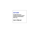
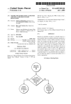
1
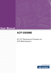
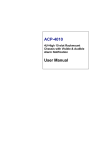
Packing List
Specifications
SNMP-1000-E1B1:
• One SNMP/HTTP system manager kernel board
mounted on a PCI/ISA carrier board
Hardware Specification
• One 6-pin to 8-pin cable for CPU card connection
• Onboard 512KB Flash ROM and 512KB SRAM
• One 2-pin cable for watchdog timer detection
• Onboard 10/100 Mbps Ethernet adapter
• One bracket for use on ISA slot
• 1 RS-232 serial port up to 9600 baud rate
• Three thermal sensor board with cable sets
• 1 SM bus interface for PC system healthy status
monitoring
• One 9-pin to 9-pin modem cable
• One SNMP-1000-B1 startup manual
• One CD containing utility program, SNMP MIB file and
user's manual (in pdf format)
SNMP-1000-E2B1:
• One SNMP/HTTP system manager kernel board
mounted on a carrier board for chassis
• One 6-pin to 8-pin cable for CPU card connection
• One 2-pin cable for watchdog timer detection
• One 9-pin to 12-pin serial port cable for COM2 of CPU
card
• One RJ-45 cable with bracket for external LAN connection
• One 9-pin to 9-pin modem cable
• One SNMP-1000-B1 startup manual
• One CD containing utility program, SNMP MIB file and
user's manual (in pdf format)
SNMP-1000-LCD:
• One message display module
If any of these items are missing or damaged, contact
your distributor or sales representative immediately.
Note 2:
• 1 SM bus interface for up to 8 external temperature
sensors
• 9 fan tachometer inputs (7 inputs for SNMP-1000-E2B1)
• 1 on-board temperature sensor
• 1 LCM message display interface
• Detect time-out signal of system watchdog timer
• 4 power good signals(SNMP-1000-E1B1)
• 8 digital inputs (SNMP-1000-E1B1)
• 4 digital outputs (SNMP-1000-E1B1)
Dimensions
• Kernel module (SNMP-1000-E1B1): 40.5 mm X 93
mm
• PCI/ISA carrier module (SNMP-1000-E2B1):
175 mm x 107 mm
• Carrier board for chassis (SNMP-1000-E2B1):
55 x 115 mm
Sensor Input Specification
• One 8-pin cable for SNMP connection
Note 1:
• CPU: 80188 compatible 20 MHz
For detailed contents of the SNMP-1000-B1
please refer to the enclosed CD-ROM or disk
(in PDF format).
Acrobat Reader is required to view any PDF
file. Acrobat Reader can be downloaded at:
www.adobe.com/Prodindex/acrobat/readstep.html (Acrobat is a trademark of Adobe.)
• Voltage Inputs: +5VDC, -5VDC, 5VSB, +3.3VDC, +12
VDC, -12 VDC
• Temperature Sensors: LM75 digital temperature sensor, I2C interface, -30 ~ +125°C (-22 ~ 257°F)
• Fan Speed Monitor: Up to 9 fans, 700 ~ 10000 RPM
• Power Good / Digital Input:
High: > 2.4 VDC, Low: < 0.8 VDC
System Status Monitoring and Management
• Real-time healthy status monitoring: Provides realtime
status display in HTTP/Java graphical format
• History log graphic display and data down load
• Alarm event log
Alarm Notification
For more information on this and other Advantech products,
please visit our website at:
http://www.advantech.com
For technical support and service, please visit our
support website at:
http://service.advantech.com.tw/eservice/
This manual is for the SNMP-1000-B1.
Part No. 20021000C1
Printed in Taiwan
1
1st Edition
January 2005
SNMP-1000-B1Startup Manual
• E-mail: Can set up to 4 addresses to receive e-mails
• Alarm message display on the optional LCD display
module
• SNMP trap: Notify up to 8 SNMP administrators
• Pager notification: Dial out through external modem to
send message to up to 8 pagers.
• Audible alarm sound
SNMP-1000-B1: Intelligent SNMP/HTTP Remote System Manager
SNMP-1000-B1: Intelligent SNMP/HTTP Remote
System Manager Startup Manual
Supported Protocols
• TCP, UDP, IP, ICMP, DHCP, BOOTP, ARP, SNMP, HTTP,
Telnet
Jumpers and Connectors
Management Functions
• Web-based remote configure, control and monitor
Label
J1
Jumpers
Function
External Buzzer Connector
• Remote reset, power down and power up.
• Remote digital output signal control
• Remote message display control
• Firmware upgrade from serial port and Ethernet port
• Modem dial in (console mode only)
LCD Message Display Module with Keys
• LCD module: 2 rows, 16 characters, with backlight
• Dimension: 147 mm X 42 mm
• 5 Keys: Up, down, enter, escape, alarm sound off
Optional Backup Battery
• Charge time: 3 hr
• Battery type: Li-Ion
• Battery capacity: 1800 mA-H (full charged, for 45~50
minutes operation, depending on the output used)
• Battery life: 1 year @ 20° C, 80% capacity after 500
cycles of charge and discharge
Power Consumption
• 5 V @ 550 mA
Caution: The SNMP-1000-B1 is provided with a batterypowered Real-time Clock circuit. There is a danger of
explosion if battery is incorrectly replaced. Replace only
with same or equivalent type recommended by the manufacturer. Discard used batteries according to manufacturerís instructions
Environmental Specifications
• Storage temperature: -20 ~ 70° C (4° F ~ 158° F)
• Operating temperature: 0 ~ 60° C (32° F ~ 140° F)
• Relative humidity: 5 ~ 95% RH non-condensing
Notice: Only Advantech's new full-sized CPU cards and
industrial ATX motherboard can be monitored,
including PCA-6002, PCA-6003, PCA-6004,
PCA-6005, PCA-6181, PCA-6183, PCA-6184,
PCA-6185, PCA-6186, PCA-6187, PCA-6188,
PCA-6277 (rev. B), AIMB-740, AIMB-741,
AIMB-742, AIMB-744 and newer.
The following CPU cards cannot be monitored: PCA6155V, PCA-6168, PCA-6175, PCA-6176,
PCA-6178, PCA-6179, PCA-6180, PCA-6275,
PCA-6276, PCA-6277 (rev. A), PCA-6278,
PCA-6359, and earlier
2
SNMP-1000-B1Startup Manual
Label
CN1
CN2
CN3
CN4
CN5
CN7
CN8
CN9
CN10
CN11
CN12
CN13
CN14
CN15
CN16
CN17
CN18
CN19
CN20
CN21
CN22
CN23
CN24
CN26
BT1
MCN1
MCN2
MJ1
MSW1
FAN1
FAN2
FAN3
FAN4
FAN5
FAN6
FAN7
FAN8
FAN9
Connectors
Function
External Power Connector
10/100Base-T LAN Connector
System SMBus Connector
Temperature Sensor Connector
10/100Base-T LAN Connector
Temperature Sensor Connector
RS-232 Connector
RS-232 D-SUB Serial Port
LCM Message Display Connector
Kernel Board Connector
Kernel Board Connector
Backplane Voltage Input Connector
Digital Input Connector (DI1~DI8)
Digital Output Connector (DO1~DO4)
Power Good Input Connector
Alarm Reset Connector
LED Indicator Connector
CPU Card Interface Connector
Chassis and Watchdog Timer Connector
Power Good Input Connector
Power Good Input Connector
Power Good Input Connector
Power Good Input Connector
External HDD LED Connector
External Backup Battery Connector
Kernel Module Interface
Kernel Module Interface
Bypass Password Protection Connector
Test Mode & Normal Mode Switch
FAN Connector
FAN Connector
FAN Connector
FAN Connector
FAN Connector
FAN Connector
FAN Connector
FAN Connector
FAN Connector
Getting Started
Configuring the SNMP-1000-B1
Before using your SNMP-1000-B1 SNMP/HTTP intelligent
system manager, you need to configure it by using a PC.
You can configure it from the serial port by using a PC with
terminal emulator software such as Hyperterminal of Windows 98/NT. You can also configure it from the Ethernet
port by using Telnet or using a browser such as Netscape
CommunicatorTM or Microsoft Internet ExplorerTM. Some
parameters can only be set through the serial port due to
security reasons.
Ethernet. There are four ways to determine the IP
address:
A setup software utility can be found in the utility CDROM
shipped with the SNMP-1000-B1. It helps you to set up a
number of the SNMP-1000 system managers with same
configuration. You can save current configuration to a file
and copy it to other modules.
• The default IP address is 172.20.x.x where x.x are the
last four digits of the Ethernet MAC address. The MAC
address is labeled on the kernel module. For example, if
the MAC address is 00 E0 d8 03 15 36 (hexadecimal),
the IP address is then 172.20.21.54.
Before you can configure your SNMP-1000-B1 module,
you need first install your SNMP-1000-B1 and power it up.
Connect it to a network through its LAN port, or connect
its serial port to your PC using a "null modem" cable with
reversed Tx & Rx signals at one end. This cable is available from Advantech. (Part number: 1700091801)
• You can read the IP address in console mode under
"Agent Configuration".
When all the cables are well-connected, you can power up
the SNMP-1000-B1. A green LED on the kernel module
indicates that 5V power is supplied to SNMP-1000-B1.
Then it starts a self-testing procedure. It takes around 5
seconds, then it is ready to work.
Configuring through the serial port
The configuration example below if for Windows Hyperterminal (Windows95/98/ME/NT/2000/XP).
1. Start Hyperterminal by clicking on "Accessories" program group.
• You can read the IP address through the LCM display if
your SNMP-1000-B1 is connected to the LCM display
module.
• You can find all SNMP-1000-B1s connected on the
same network by using the setup utility.
Configuration using Telnet
Configuration using Telnet is basically same as using
serial port connection. First, make sure your computer has
a TCP/IP network and a web browser installed. In the
address line type "Telnet xxx.xxx.xxx.xxx." Here
xxx.xxx.xxx.xxx is the IP address of the SNMP-1000-B1.
Then the SNMP-1000-B1 will prompt you to enter user
name and password.
2. Enter a name and choose an icon for the connection.
Configuration using a Web Browser
3. In the "Connect using" box, select "Direct to COMx."
Using a web browser is the easiest way to configure the
SNMP-1000-B1. Type in the URL "http://xxx.xxx.xxx.xxx."
Here xxx.xxx.xxx.xxx is the IP address of the SNMP1000-B1. Then the SNMP-1000-B1 will prompt you to
enter user name and password.
Here “x” is the number of COM ports you are using to connect to the SNMP-1000-B1.
4. Set the serial port of your PC to “9600 bps,” “8 data
bits,” “No parity,” and “1 stop bit with no flow control.”
5. Press the "Enter" key on your PC, then the SNMP1000-B1 will prompt you to enter administrator user name
and password. The default administrator user name is
"advantech" and password is "admin."
Note: Access through Telnet or serial port is permitted
only with the "Admin User Name" and "Admin
User Password" set in Control Group.
Remote access through a phone line
SNMP-1000-B1's command mode can be accessed
remotely through a phone line. The SNMP-1000 -B1 has
to be connected to a phone line through a modem. Your
PC has to be connected to a phone line through a modem
too.
You can use HyperTerminal of the Windows system or
other dialing software tools. Please refer to the user's
manual of your dialing program for the setting details.
After entering the password, you can access the configuration menu of SNMP-1000-B1.
FCC: This device complies with the requirements in part
15 of the FCC rule.
Operation is subject to the following two conditions:
1. This device may not cause harmful interference, and
2. This device must accept any interference received,
including interference that may cause undesired operation.
Communicating through Ethernet
To communicate with SNMP-1000-B1 through Ethernet,
you need a computer with Ethernet and a TCP/IP network
installed. You need to know the IP address of the SNMP1000-B1 before you can communicate with it through the
CAUTION!! Danger of explosion if battery is incorrectly replaced. The battery doesn’t need to be
charged. Replace only with Advantech-specified batteries.
SNMP-1000-B1 Startup Manual
3
FAN1FAN2 FAN3
CN5
CN1
CN4
CN18
FAN4FAN5 FAN6
CN7
CN2
FAN7FAN8 FAN9
CN12
CN11
BT1
CN8
CN10
CN14
CN9
CN19
CN13
CN3
CN20
CN26
J1
CN15
CN24 CN23 CN22 CN21
Connector locations of PCI/ISA I/O extension board
Connector locations of carrier board for IPC chassis
4
CN17
SNMP-1000-B1Startup Manual