1
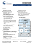
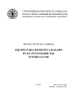
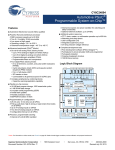
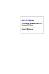
Migrating Designs from CY7C64x13
to CY7C64215 (enCoRe™ III)
AN6073
Author: Jacob Tomy
Associated Project: No
Associated Part Family: CY7C64215
Associated Application Notes: None
Abstract
AN6073 describes the differences and similarities between Cypress’s CY7C64x13 and CY7C64215 full-speed USB microcontrollers with the intent of guiding customers when migrating designs from the CY7C64x13 to the new generation CY7C64215
microcontroller.
Introduction
Cypress Semiconductor highly recommends that its new generation enCoRe™ III (CY7C64215) be used for new fullspeed USB peripheral designs instead of the legacy
CY7C64x13. Customers who are currently designed in with
the CY7C64x13 are encouraged to migrate to new designs
with the CY7C64215. The reasoning behind this is that, at a
higher level, enCoRe III has the following enhancements over
CY7C64x13:
This application note highlights the similarities and differences between Cypress full-speed USB microcontrollers—the CY7C64x13C microcontroller and enCoRe
III—and serves as a guide book when migrating designs from
CY7C64x13 to CY7C64215. This application note assumes
that the reader is familiar with USB fundamentals and the legacy Cypress CY7C64x13 microcontroller.
Features and Architecture of the Two
Microcontrollers
■
Faster/better performance (processing speed)
■
Broader operating voltage range
CY7C64x13 Microcontroller
■
Larger on-chip memories (FLASH and RAM)
■
enCoRe III is in-system programmable and
reprogrammable
■
Improved Serial Interface Engine (SIE)
The CY7C64x13 is an 8-bit full-speed USB microcontroller
that follows the Harvard architecture with USB optimized
instructions. It requires an external 6 MHz crystal for operation and is capable of providing a 12 MHz internal CPU clock
and a 48 MHz internal clock as well.
Also, as the device name implies (enCoRe – enhanced component reduction) it integrates many of the components normally required by a USB microcontroller, thus leading to lower
system Bill of Materials (BOM) costs. Some of the features
integrated are:
■
Internal Oscillators – Main Oscillator and Low-Power oscillator for sleep timer functions
■
Internal regulator – 3.3 V with integrated pull-up resistor
■
System Resources like I2C, user-configurable low-voltage
detection, voltage reference etc.
■
User configurable functions (predefined and available as
modules)
The enCoRe III also uses contemporary development/emulation tools, which makes development easier.
August 17, 2011
The device has a PROM-based 8-KB program memory and
256 bytes of SRAM for stack and data variables. It has four
GPIO ports with maskable interrupts on all pins. Ports 0,1 and
2 are capable of sinking 7 mA per pin and port 3 can sink up
to 12 mA per pin. Each GPIO port can be configured as
inputs with internal pull ups, open drain outputs or traditional
CMOS outputs. A DAC port with programmable current sink
outputs is available on the CY7C64113.
The CY7C64x13 has an integrated Master/Slave I2C-compatible Controller (100 kHz) enabled through General-Purpose
I/O (GPIO) pins and an integrated Hardware Assisted Parallel
Interface (HAPI) for data transfer to external devices. Also
integrated in the device is a 12-bit free-running timer with
1-μs clock ticks, a watchdog timer, and internal power on
reset.
Document No. 001-15340 Rev. *A
1
AN6073
The CY7C64x13 has an integrated transceiver and can support five user configured endpoints—up to four 8-byte endpoints or
up to two 32-byte endpoints. It also conforms to USB specification v1.1 and USB HID specification v1.1. It is available in commercial temperature range (0 to 70°C) and can operate from 4.0 V to 5.5 V DC.
Figure 1. Block Diagram of the CY7C64x13 Microcontroller
Logic Block Diagram
6-MHz crystal
PLL
48 MHz
Clock
Divider
12-MHz
8-bit
CPU
USB
Transceiver
USB
SIE
D+[0] Upstream
D–[0] USB Port
12 MHz
RAM
256 byte
Interrupt
Controller
8-bit Bus
PROM
8 KB
GPIO
PORT 0
6 MHz
P0[7:0]
P1[2:0]
GPIO
PORT 1
12-bit
Timer
P1[7:3]
P2[0,1,7]
GPIO/
HAPI
PORT 2
Watchdog
Timer
P2[2];
P2[3];
P2[4];
P2[5];
P2[6];
Latch_Empty
Data_Ready
STB
OE
CS
Power-On
Reset
GPIO
PORT 3
I2C
Interface
P3[2:0]
High Current
Outputs
P3[7:3]
Additional
High Curr ent
Outputs
SCLK
SDATA
2
*I C- compatible interface enabled by firmware through
P2[1:0] or P1[1:0]
enCoRe III – CY7C64215 Microcontroller
■
Four digital enCoRe III peripherals provide:
This microcontroller integrates certain features that are normally added externally to USB micros. In addition it has configurable peripherals and preconfigured system resource
blocks.
❐
8-bit PWMs
❐
Full-Duplex UART
❐
Multiple SPI Masters or Slaves
The CY7C64215 has an 8-bit Harvard Architecture Processor
with speeds up to 24 MHz and two 8x8 Multiply, 32-bit Accumulate blocks. It has an operating voltage range from 3.0V to
5.25V and is built for commercial temperatures (0 to 70°C).
❐
Connectable to all GPIO Pins
enCoRe III has four 8-bit digital peripherals as well as analog
peripherals with the following base capabilities:
■
Analog enCoRe III peripheral provides:
❐
Up to 14-bit incremental ADCs
August 17, 2011
These blocks are highly configurable and can be combined to
produce complex peripherals. For the developers’ convenience a set of preconfigured functions is available with the
development tool in the form of selectable ‘User Modules’.
The enCoRe III’s program memory is flash based, which
makes it reprogrammable. It is also in-system programmable.
The flash supports partial updates made possible with
EEPROM emulation. enCoRe III’s flash also has four flexible
Document No. 001-15340 Rev. *A
2
AN6073
protection modes available. It has a 1K SRAM for data variables and stack.
Figure 2. Block Diagram of the CY7C64215
The device has an integrated full-speed USB SIE with four
unidirectional data endpoints and one bidirectional control
endpoint. It has a dedicated 256-byte buffer for the endpoint
FIFOs and is USB 2.0 compliant. The full-speed USB block
does not require any external components for operation. It
has an internal oscillator and integrated 3.3V voltage regulator.
enCoRe III provides for precision programmable clocking. It
has an internal main oscillator (IMO)24/48MHz with ±4%
accuracy. It also has a low power oscillator for the sleep
timer. With USB communications, the IMO can lock to the
incoming USB traffic to provide an accuracy of ±0.25%.
All of the device’s GPIOs can be configured as Pull Up, Pull
Down, High-Z, Strong, or Open Drain Drive Mode. It has configurable interrupts and 25-mA sink capability on all GPIOs.
As a part of the component reduction, enCoRe III provides
the following System Resources in addition to the configurable blocks.
■
I2C™ Slave, Master, and Multi-Master to 400 kHz
■
Watchdog and Sleep Timers
■
User-Configurable Low Voltage Detection
■
Integrated Supervisory Circuit
■
On-chip Precision Voltage Reference
It also comes with complete Development Tools.
■
Free Development Software (PSoC Designer™)
■
Full-Featured In-Circuit Emulator and Programmer
■
Full Speed Emulation
■
Complex Breakpoint Structure
■
128K Bytes Trace Memory
August 17, 2011
The CY7C64x13 and the CY7C64215 are both 8-bit microcontrollers with an integrated Full-Speed USB Serial Interface
Engine (SIE). While they are similar in some of the features,
hardware blocks, and integrated functionalities, they differ
vastly in certain aspects. Understanding these differences is
necessary to port designs from CY7C64x13 to CY7C64215
successfully. The differences between these two microcontrollers, at a higher level, are listed in the following table. This
is followed by a detailed look at some of the differences along
with pseudo code to aid in design migration.
Document No. 001-15340 Rev. *A
3
AN6073
Differences Between the Two Microcontrollers
Features/Characteristics
CY7C64x13
CY7C64215
CPU core
M8B core
M8C core
Memory Organization
8 KB PROM, 256 byte RAM
16K FLASH, 1K SRAM, 256 bytes of dedicated USB endpoint RAM
Serial Interface Engine
The SIE’s response to USB packets depends on the
endpoint modes. Sends and receives data from the
appropriate endpoint FIFO, enabling/disabling flags
during this function.
The SIE’s response to USB packets depends on the endpoint modes. It sends and receives data from the USB
SRAM through the PSoC Memory Arbiter (PMA). The
PMA manages potentially conflicting SRAM access
requests from the SIE and M8C. The SIE also identifies
the Start-of-Frame (SOF) and saves the frame count. The
firmware is required to enable PMA channels before loading the USB SRAM locations with IN/OUT data.
Interface
I2C and HAPI interfaces possible. I2C supports a 100
KHz serial link. HAPI can support 8, 16, or 24 bits
wide bus for data transfer with an external device.
Option available to choose from hardware and software
I2C user modules. The I2C hardware is available as a
system resource and can be configured to operate using
the APIs. Neither the software nor hardware I2Cs require
digital/analog peripherals. Other communication interfaces that can be built using the configurable blocks are
SPI master, SPI slave and UART interface user modules.
No preconfigured user module is available for HAPI. The
developer can use the available blocks to build a HAPI
interface.
Endpoint
1 control endpoint, 4 data endpoints. The endpoints
use higher address bytes of the SRAM and the actual
value depends on the number and size of the endpoints
1 control and 4 data endpoints. Dedicated 256 byte buffer
for all the endpoints.
GPIO
The GPIOs can be configured as inputs with internal
pull ups (Resistive Mode), output Low, Output High or
Hi-Z mode. Falling or rising edge interrupts can be
supported at all port pins.
Each GPIO can sink up to 25 mA of current and have configurable (falling edge, rising edge and change from read)
interrupts at all GPIOs. Pull up, pull down, High-Z, Strong
or Open Drain Drive Modes on all GPIOs.
Interrupt
The first lower 26 bytes of PROM are dedicated for 13 The CPU utilizes an interrupt controller with up to 20 vecinterrupt vectors.
tors from address 0x0000 to 0x002F and then from
0x0040 to 0x0068 flash locations.
Clocking
External crystal used in conjunction with the internal
PLL/oscillator or accurate external clock.
No option for external crystal. Input for external clock provided. Internal 24 MHz and 32 KHz oscillators provided.
These two oscillator frequencies together with clock dividers can provide a wide range of clocks.
Reset
Power on reset (POR) and watchdog reset (WDR).
Power on reset (POR), watchdog reset (WDR) and Internal Reset (IRES—occurs during boot sequence when
FLASH reads are considered invalid by SROM code).
Suspend
The device can be put into suspend by writing to the
Processor Status and Control Register (address
0xFF). Only the USB receiver and GPIO interrupt
logic is on. The run bit at address FF should be set to
resume the part out of suspend. The instruction following suspend is normally pre-fetched and so is usually programmed as a ‘nop’.
The device is put into suspend by setting the sleep bit in
the CPU_SCR0 register. The USB wake interrupt should
be enabled to enable the device to resume USB operation. Two instructions following ‘Sleep’ are pre-fetched
and so are programmed to be ‘nop’s.
Voltage regulator
Integrated voltage regulator and pull up resistor on chip. If
External voltage regulator (3.3V) required at Vref
input on the microcontroller. The pull up resistor at the the chip uses a 3.3V supply, the regulator can be put in
D+ pin should be provided externally to the Vref pin. pass-through mode (the 3.3V reference is provided from
the supply itself).
Stack
Separate Program Stack and Data Stack.
Single Stack for program and data.
DAC port
Has a 4-bit DAC that can be enabled to sink current
(programmable output current sink levels) or can be
used as an input with internal pull up.
The user module for DAC is not explicitly provided. However, users can build, depending on resources they can
allocate, a 4/6/8 bit programmable output sink/source current or a DAC for programmable output voltage levels.
August 17, 2011
Document No. 001-15340 Rev. *A
4
AN6073
CY7C64x13
CY7C64215
Timer
Features/Characteristics
The CY7C64x13 has a 12-bit free-running timer that
is clocked with a 1 MHz source clock. Two interrupts
are provided at 128 μs and 1.024 ms.
The user has available digital peripherals to build 8, 16,
24 bits wide timer (depending on resource availability),
with interrupts at desired intervals. Additionally, the
enCoRe III also has a sleep timer (sleep timer interrupt, to
wake up periodically and poll for interrupts) and watchdog
timer as part of the system resources.
Development Tools
Uses the CY3654 platform board and the CY3654P03 personality board for to assist in emulation/debugging during firmware development. Emulation is achieved through an on-board FPGA
programmed with the user firmware. The CY3654P03 personality board can also accommodate flexpod to aid in on-board emulation.
Based on Cypress PSoC development suite. GUI based
suite (USB Setup Wizard) to develop/build USB functionality. Uses ICE cube and the CY3664 application board
for emulation/debugging. Actual target silicon programmed with user firmware is used in emulation. Onboard emulation is made possible using ICE and the
CY7C64215 flex-pods.
Programming
Out of system programming only. Use of a separate
pin for programming and high programming voltages
(12V).
In-system programming possible using programming
headers on the board. Programming voltage as low as
2.7V.
Supply Voltage
4.0 to 5.25V. For reliable USB operation, the supply
voltage should be between 4.35 and 5.25V.
3.0 to 5.25V. Can operate USB at 3.3V powered externally. Mechanism must be provided to detect Vbus connection to engage the D+ pull up and start
communications.
Clocking
Memory Organization
The CY7C64x13 microcontroller requires an external crystal
or an external clock for operation. When an external crystal is
used, it provides the reference frequency for the internal PLL.
The load caps and bias resistors are internal to the chip. They
also impose a requirement on the load capacitance of the
crystal (15–18 pF). When an external oscillator/clock is used,
the clock is to be connected to the XTALIN pin with the
XTALOUT pin left open. The CPU operates at 12 MHz.
The CY7C64x13 has 8 KB of PROM and 256 bytes of data
RAM. The SRAM is partitioned into Data Stack, Program
Stack, user variables, and USB endpoint FIFOs. The endpoint FIFOs can be configured (size and number of endpoints) by writing to bits 7 and 6 in the USB Status and
Control register (0x1F). The unused SRAM locations can be
used for user variables. The program stack starts at 00h and
grows forward. The data stack grows backwards and so firmware must write an appropriate value into the DSP register to
prevent conflict with the endpoint FIFO address.
The CY7C64215 microcontroller has an internal oscillator
that provides a 24 MHz clock, accurate to 8% over temperature and voltage. The enCoRe III system clock can be
sourced by the internal 24 MHz clock or by an accurate external clock. The system clock in turn can be divided by programmable dividers and can source different modules in the
device. This can be done using the PSoC Designer tool,
Device Editor view – global resources section. The external
clock input at P1[4] can be enabled by setting bit 2 in the
OSC_CR2 register at location 1,E2h.
Figure 3. CY7C64x13 Stack/SRAM/Endpoint FIFO Setup
Address
0x00
Program Stack Growth
When communicating using USB, the 24 MHz IMO can self
tune to an accuracy of ±0.25%. To enable this (required
unless an accurate external clock is used), the ‘EnableLock’
bit (bit 1) in register USB_CR1 (1,C1h) should be set by firmware. This is provided in the USB_Start API function.
Data Stack Growth
The enCoRe III CPU can run at eight different speeds (24
MHz to 93.7 KHz); this allows for performance and power
requirements to be tailored to the desired application. This is
made possible by using bits [2:0] in the OSC_CR0 register
(location 1,E0h). This can also be achieved in the development tool – Device Editor view, global resources section.
The CY7C64215 also has an internal 32 KHz low power
oscillator for sleep timer and watchdog timer. These clocks,
along with the programmable clock dividers, make it possible
to have a wide range of frequencies in the microcontroller.
August 17, 2011
User Variables
USB FIFO space for five endpoints
Address
0xFF
Document No. 001-15340 Rev. *A
5
AN6073
DSP register. Firmware must set DSP to avoid memory conflicts with the endpoint FIFOs.
Figure 4. enCoRe III Stack/SRAM Setup
00h
Page 0
SRAM
256
Bytes
Page 1
SRAM
256
Bytes
Page 2
SRAM
256
Bytes
Page 3
SRAM
256
Bytes
FFh
Address
0x000/
0x100/
0x200/
0x300
Stack begins at 0x000/
0x100/0x200/0x300
and grows upwards
Endpoints
Stack
wraps
around
from
xFFh to
x00h
Address
0x0FF/
0x1FF/
0x2FF/
0x3FF
Top of RAM page
enCoRe III has 16 KB of FLASH, 1K SRAM for user variables
and stack. The 1K SRAM is made available using four 256byte blocks. The STK_PP register (location 0,D1h) uses bits
[2:0] to select the appropriate SRAM page for stack operations. The Stack wraps around from FF to 00h, so the user
must take precautions against overwriting data variables in
the RAM. The PSoC Designer tool automatically handles
RAM access through memory models (large and small) and
stack parameters. Default settings are large memory model
and single RAM (page 3) for stack and indexed memory
operations. User can modify parameters in the memory.inc
file for desired RAM access patterns.
Additionally, enCoRe III has a dedicated 256-byte RAM for
the endpoints. This dedicated SRAM cannot be accessed by
means of M8C instructions. It can only be accessed using
PMA (PSoC Memory Arbiter) registers. The PMA acts as the
interface between the M8C and SIE to avoid potential conflicts when accessing the same SRAM locations. When the
SIE writes data to the FIFO, the internal data bus is driven by
the SIE and not the CPU. This could lead to conflicts if the
CPU speed is greater than 12 MHz, particularly when the
value of the SysClk divider (selected in the PSoC Designer
tool) is ‘1’. In such cases, before transfer occurs the CPU
speed is brought down to 12 MHz for reliable operation. This
occurs with OUT transfers and the condition is taken into
account in the Read_OutEP API function.
Stack
The CY7C64x13 has separate program and data stacks. The
data stack grows from higher memory address to lower. The
data stack starting location can be configured by writing to the
August 17, 2011
The CY7C64215 has a single stack for program and data.
The stack can be in any of the 4 SRAM banks. By default the
stack is in page 0, but can be changed using bits [2:0] in the
STK_PP register. Set the STK_PP register [2:0] value in the
beginning of the program and do not change after it has
grown. The stack wraps around from FFh to 00h. Firmware
should ensure that the stack doesn’t overlap with user
defined variables in the RAM.
The CY7C64x13 has 1 control endpoint and 4 data endpoints. This can be configured (the number of endpoints and
their sizes) by writing to bits 7,6 in USBCR register (0x1F).
Up to four 8-byte data endpoints or two 32-byte data endpoints are possible. The endpoint FIFOs reside in the upper
RAM locations. The unused RAM locations are used for data
variables.
The CY7C64215 also has 1 control and 4 data endpoints. It
has a dedicated 256-byte buffer for the endpoints in addition
to user RAM. This 256-byte buffer can be configured to be
shared between the 4 data endpoints. The development tool,
PSoC Designer by default, configures each of the 4 endpoints with 64 bytes each. This setting can be manually
changed to suit the designer’s needs.
CPU Registers
An important difference between the two microcontrollers that
must be accounted for is the location of CPU registers. Most
of the registers in the CY7C64x13 and the CY7C64215 are
present in different locations. In addition, some of the registers for HAPI and DAC control are not present in the
enCoRe III. Almost all USB registers in the CY7C64x13 have
an equivalent in the enCoRe III. One main difference
between CPU registers in the microcontrollers is that
enCoRe III has 512 8-bit registers that come in 2
banks—Bank0 and Bank1. When writing to a register the
user must also account for its bank. Bank0 is the default. Bit
4, XIO in the CPU_F register (located at F7h) must be set to
access the upper 256 registers. There are also system macros provided for this—SetBank0 and SetBank1 in the development tool. The CPU_F register can be accessed (read or
written) no matter what bank is used.
Interrupts
In the CY7C64x13 microcontroller, the first lower 26 bytes of
PROM are dedicated for 13 interrupt vectors. Some of the
interrupts available are USB bus reset, 128-μs, 1-ms, USB
endpoints interrupts, DAC, GPIO, and I2C interrupt in that
order from the lower ROM address location. The lower-number interrupts have the highest priority. Interrupt latency is
based on time for current instruction, time to change program
counter to interrupt address (13 cycles), and time for LJMP
instruction to execute (7 cycles).
Document No. 001-15340 Rev. *A
6
AN6073
The CY7C64215 CPU uses an interrupt controller with up to
20 vectors. Flash locations 00h to 2Ch are dedicated to
PSoC interrupt vectors. Flash locations 40h to 64h are dedicated to USB, I2C, and sleep timer interrupt vectors. Interrupt
latency is based on time for current instruction, time to
change program counter to interrupt address (10 cycles), and
time for LJMP instruction to execute (5 cycles).
Program Counter
Figure 5. Interrupt Vectors and Program Memory
Organization
The 16-bit program counter in the CY7C64215 allows direct
access to 16K of the FLASH space. This is actually two 8-bit
registers, PCH and PCL
CY7C64x13
CY7C64215
14-bit Program Counter
16-bit Program Counter
Address
0x0000
Address
0x0000
12 Interrupt Vectors
+ 1 Reserved
10 Interrupt Vectors
Differences Between M8B and M8C Processor Cores
The M8B CPU core was used in Cypress legacy devices.
Since then we’ve moved to the M8C core, which is a newer
CPU core—better, faster, and with a more efficient instruction
set.
0x002F
0x0040
0x001A
10 Interrupt Vectors
Program Memory
The CY7C64x13 uses a 14-bit Program Counter that allows
access to 8 KB of PROM. The lower eight bits are incremented as instructions are loaded onto it. The higher six bits
are incremented when an XPAGE instruction is executed,
i.e., the last instruction to be executed following a 256-byte
sequential code access is an XPAGE instruction.
0x0068
Some of the major changes between the M8B and M8C are
given in the table below. There are changes in the assembler
instructions between the two processor core versions. There
are also some new instructions added in the M8C core.
These existing M8B instructions with equivalent M8C instructions and the new M8C instructions are tabulated in the
Appendix.
Program Memory
0x1FDF
0x3FFF
Feature
M8B
M8C
Accessing across 4K Boundary of 8K
ROM
Limited, can only ‘call’ from lower to upper 4K
No limitations (LJMP, LCALL instructions)
ROM Size Access
Limited to 8K
Access up to 64K
RAM Size Access
Limited to 256 bytes
Access up to 4K (extended address bits, can be
divided between RAM and IO registers)
Instruction Set
Irregular/non-orthogonal
Many more instructions, nearly orthogonal
access
Program/Data Stack
Two separate stacks, grow toward each other
Single stack
Bit Test/Set/Clear
No direct support
Supported with expanded instruction set
Crossing 256-byte Page Boundaries
Assembler inserts XPAGE automatically
No XPAGE; micro adds one clock cycle on page
crossings
Some of the other important M8C changes not mentioned in
the table are:
■
The Carry and Zero flags have moved to a new FLAG
register.
■
Because of the separate flag register, interrupts (and reti)
store (restore) three bytes instead of two.
■
The Interrupt Enable signal, previously handled with EI/DI
instructions, is now a bit in the flag register. Logical operations on the flag register perform the equivalent EI / DI
function.
■
Generally, most instructions have four new addressing
modes for a total of seven for each function.
August 17, 2011
Watchdog
In the CY7C64x13 microcontroller, the watchdog reset occurs
when the watchdog timer rolls over. Writing any value to
watchdog restart register (location 0x26) clears the timer. The
roll-over time for this timer is approximately 8 ms. Bit 6 of the
Processor and Control register (location 0xFF) registers this
event. Firmware must periodically (at least once every rollover time) clear this register for proper operation of the microcontroller.
The CY7C64215’s watchdog is sourced by the internal lowpower oscillator or the 32.768 KHz external crystal oscillator.
Bit 7 of the OSC_CR0 register (location 1,E0h) is used for
this purpose. The watchdog period is configured using bits
Document No. 001-15340 Rev. *A
7
AN6073
[4:3] of the OSC_CR0 register and can range from 6 ms to
3s, depending on the value written.
Sleep and Wake-up Timer
CY7C64x13 does not have a dedicated sleep/wake-up timer.
However, the user can employ an external RC circuit connected to a GPIO pin for this purpose. The selected GPIO pin
is connected to ground through a capacitor and to Vdd
through a resistor. For use, the pin is first configured to output
a low. This is achieved by writing a ‘0’ to the appropriate bit of
the port data register. The capacitor discharges through the
path created by the low output pin. The configuration register
and port data register are modified for Hi-Z and rising edge
interrupt polarity. The node is then allowed to charge up
through the resistor. When the node exceeds the threshold of
the pin, a GPIO interrupt occurs. The check for various conditions can be done in the interrupt ISR. The time for the node
to rise up to the threshold depends on the time constant of
the RC network. The interrupt ISR must also contain code to
discharge the capacitor and re-enable the RC timer operation. The time constant is effectively the sleep time of the circuit. A typical RC connection for the explained setup with
capacitor charge/discharge is shown in Figure 6.
Figure 6. Typical RC Connection
Vdd
Vdd
Vdd
When pin
configured to Hi -Z
When pin
configured to
OUTPUT LOW
R
R
R
GPIO pin
C
C
Capacitor
Discharge
In enCoRe III, the sleep timer is sourced by the 32 KHz oscillator (internal low-power oscillator or external crystal). When
the internal low-power oscillator is selected as the clock
source, sleep intervals are approximate. However, the sleep
period can be configured by writing to bits [4:3] in the
OSC_CR0 register. These bits also set the watchdog period
and so the user must choose an appropriate value based on
the requirements for both sleep and watchdog period.
Timer
The CY7C64x13 has a 12-bit free-running timer that is
clocked with a 1 MHz source clock. Two interrupts are provided at 128 μs and 1.024 ms. The 1.024-ms interrupt is particularly used in timing USB events. The firmware can directly
read the 12-bit value of this register at any time. This 12-bit
register helps to time events that are up to 4 ms apart.
The CY7C64215 (enCoRe III) has a sleep timer (sleep timer
interrupt, to wake up periodically and poll for interrupts) and
watchdog timer as part of the system resource. The sleep
timer and watchdog timer are sourced by the 32 KHz source.
Accuracy levels decrease when the ILO is chosen as the
32 KHz source. Additionally, the user can also use the digital
blocks to build 8, 16, 24 bits wide timer (depending on
resource availability). The clock for this timer can be the system clocks, other PSoC blocks and external pins routed
through the global inputs. There is no 1-ms timer function
August 17, 2011
GPIO pin
GPIO pin
C
Capacitor Charge
provided explicitly for the enCoRe III device. However, the 8bit PWM can be configured to function as a 1-ms timer with
interrupts. Alternatively, the VC3 clock signal can also be
configured to provide 1-ms interrupts. The enCoRe III also
provides SOF interrupts every 1 ms. The details on this are
given in the firmware porting section of this application note.
Voltage Regulator
An external 3.3V voltage regulator is required and should be
connected to the Vref pin in the CY7C64x13. An external pull
up resistor (~1.3 Kohm) should be connected between this
pin and the D+ pin. The 3.3V regulator is normally sourced by
the Vbus, due to the USB spec requirement that the pull up at
D+ should be disabled when there is a Vbus disconnect.
The CY7C64215 has an internal 3.3V regulator and an internal pull up resistor. This resistor is disabled at reset and
should be enabled by the firmware. The API function
USB_Start (Device, Operating Voltage) takes care of this in
addition to unconfiguring the device and setting it to address
0. This function also sets the proper mode for the voltage regulator (pass-through or regulating) depending on the supply
voltage—achieved by writing to the RegEnable bit (bit 0) in
USB_CR1 register (address 1,C1h). If the device is self powered, then firmware should provide Vbus detection and then
call the USB_Start function.
Document No. 001-15340 Rev. *A
8
AN6073
■
USB Bootloader
enCoRe III supports in-system programmability. This, however, requires that the chip follow serial programming protocol during programming (the programming protocol is not
USB). A 5-pin header on the system board is also required
for in-system programming.
Bootloaders are programs that reside in the device memory.
These programs make it possible to download user code to
the chip using USB protocol. The memory containing the
bootloader code should be protected to prevent it from being
changed or written to. This requires only an application on the
host and bootloader firmware on the device. At the time of
writing this application note, there are plans to include the
USB bootloader as a user module in the PSoC Designer
tool.[1]
SROM
The SROM holds code that is used to boot the PSoC device,
calibrate circuitry, and perform Flash operations. The functions provided by the SROM are called from code stored in
the Flash or by device programmers. The SROM is used to
provide interface functions to the Flash banks. The SROM
functions are accessed by executing the Supervisory System
Call instruction (SSC), which has an opcode of 00h. Prior to
executing the SSC, the M8C’s accumulator needs to load
with the desired SROM function. Attempting to access undefined functions will cause a HALT. The SROM functions execute code with calls; therefore, the functions require stack
space. The SROM functions and parameters are defined in
detail in the PSoC TRM available on www.cypress.com
Firmware porting for some of the important USB functions is
given in the following sections.
Suspend Condition
USB microcontrollers are required by specification to go into
a suspend mode when no activity is seen on the USB bus for
more than 3.0 ms. Full-speed devices must shut down the
SIE and draw only suspend current from the host while providing power to the D+ line for maintaining correct connectivity status. On the CY7C64x13 microcontroller the clock
oscillators, 12-bit timer, and watchdog timer are shut down
when the device is put into suspend. The only blocks
switched on are the USB receiver and the GPIO interrupt
logic. The run bit in the Processor Status and Control register
(Address 0xFF) should be set to resume the part out of suspend. On the CY7C64215 microcontroller the only blocks that
are switched on during suspend are the 32 KHz oscillator,
blocks clocked by this oscillator, and the supply voltage monitoring circuit. The analog blocks should be powered down by
firmware. The USB wakeup interrupt should be enabled to
assist resuming USB operation. Typical algorithms for entering suspend in the case of both microcontrollers are given
below:
CY7C64x13 Microcontroller
1.
Monitor loss of USB activity for a specific time, e.g., 3 ms.
If no activity is detected start the suspend condition;
1ms_ISR: Check bit [3] of register [0x1F] – USB Status
and Control Register for activity every millisecond. Increment counter if there is no activity and clear if there is
activity. Check if counter reaches 3 and then start suspend
steps.
2.
All GPIO set to low-power state (no floating pins).
3.
Enable GPIO interrupts if desired for wake-up; Set bit [5]
of the Global Interrupt Enable Register at address [0x20].
4.
Set suspend and run bits; mov A, 09h.
5.
Write to Status and Control Register. Enter suspend, wait
for USB activity (or GPIO Interrupt); IOWR FFh.
6.
NOP – This executes before any ISR and is prefetched by
the processor.
7.
Remaining code for exiting suspend routine.
Firmware Development
The CY7C64x13 is provided with a framework—code for
USB SIE operation. The framework provides for a defined
enumeration firmware. Descriptors for class devices are also
available.
The enCoRe III uses a different development system that
provides a GUI interface (with pull-down menus) called the
‘USB Setup Wizard’ to set up the enumeration firmware. Predefined HID Report descriptors for a 3-button mouse and a
keyboard with LED are also provided with the tool.
The USB registers in enCoRe III include the PMA read and
write registers and the USB Start of Frame register
(USB_SOFx). The USB_SOFx register provides access to
the 11-bit SOF frame number. Due to its configurability
enCoRe III provides a large number of registers to the user.
These registers are available in two different register banks.
While porting designs from the CY7C64x13, the user must
make sure of the following as far as firmware is concerned.
■
Register locations are correct.
■
Bit locations in registers (USB bus activity bit, data valid
bit, etc.) are correct.
Firmware provides for changing register banks. The banks
and registers are given in the enCoRe III data sheet and
the PSoC TRM available at www.cypress.com.
CY7C64215 Microcontroller
1.
Monitor bus activity bit for a specific time, e.g., 3 ms. If no
activity is detected start the suspend condition.
2.
Enable interrupts; call M8C_EnableGInt or set bit [0] of the
CPU_F register at location [F7h].
3.
Call the USB_Suspend API function or write a ‘0’ to bit 7
of the USB_CR0 register. This disables USB transceiver,
but maintains the USB address; USB_CR0 &= (0x7F).
Note
1. If you require a sample USB bootloader, please create a case by going to Technical Support on www.cypress.com.
August 17, 2011
Document No. 001-15340 Rev. *A
9
AN6073
4.
Write to the sleep bit of the CPU_SCR register. This powers down most of the PSoC systems including FLASH
modules, Internal main Oscillator and bandgap. Care
should be taken to disable/power down the analog blocks
during the sleep condition; call M8C_Sleep function or set
bit [3] of the CPU_SCR0 register at location FFh.
5.
Two NOPs – These execute before any ISR and are
prefetched by the processor.
6.
Remaining code for exiting suspend routine.
Data Endpoint Transfers: IN and OUT
Bulk transfer is a common data transfer mechanism used in
full-speed USB devices. Typical pseudo code for setting IN
and OUT bulk endpoints and transfer of data in both cases is
given below. A sample project with IN and OUT transfers is
available in the PSoC Designer development tool under
CY7C64215.
Interrupt on the OUT endpoint occurs when the device transfers data to the USB host that results in an ACK transaction
from the host.
5.
Set endpoint OUT to ACK mode.
6.
Transfer data to the endpoint FIFO.
7.
Set the check for valid data toggle.
8.
Use the count register to locate last occupied data space.
9.
Check to see if you are reading the last data.
10. If not, transfer data to the RAM.
11. Disable NAK interrupts.
12. Clear ACK bit in the mode register.
13. Read the rest of the data.
14. When you get to the last data, return.
CY7C64x13 Microcontroller
CY7C64215 Microcontroller
IN Transfers
The CY7C64215 (enCoRe III) uses a GUI based tool for setting up USB related information for the device. It has drop
down menus to add/edit/select Device Attributes, configuration descriptor, interface descriptor, endpoint descriptors, etc.
For endpoint descriptors, select EP1 as IN endpoint, EP2 as
OUT endpoint, both with 10-ms interval and 64 max packet
size.
1.
Bits [7,6] of the USB Status and Control Register 0x1F are
used to configure the size and number of endpoints. Bit 7
controls the size and bit 6 the number.
2.
Check if stall condition is set on the IN endpoint
3.
If the stall condition is set, then set the endpoint mode;
endpoint Stall and ACK IN. Bit 7 of register 14, 16, 42, or
44 represents stall. Bits [3:0] of these registers represent
the mode of the endpoint.
IN Transfers
1.
Enable Global interrupts; M8C_EnableGInt;
If the stall condition is not set, then set the endpoint mode
to Stall and NAK IN.
2.
Start USB user module;
USBFS_Start(0,USB_5V_OPERATION);
Interrupt on the IN endpoint occurs when the device transfers
data to the USB host that results in an ACK transaction from
the host.
3.
Wait for enumeration;
while(!USBFS_bGetConfiguration());
4.
Prime EP1 – IN endpoint;USBFS_LoadInEP(USB_EP1,
&aBuf[0], EP1SZ, USB_TOGGLE);
4.
5.
Set endpoint IN to ACK mode.
6.
Transfer data to the endpoint FIFO.
5.
Get count; bCount = USBFS_wGetEPCount(USB_EP2);
7.
Disable endpoint IN NAK interrupts.
6.
8.
Change data toggle.
Load IN endpoint; USBFS_LoadInEP(USB_EP1,
&aBuf[0], bCount & 0x00FF, USB_TOGGLE);
9.
Clear ACK bit in the mode register.
OUT Transfers
10. Reset endpoint IN.
OUT Transfers
1.
Bits [7,6] of the USB Status and Control Register 0x1F are
used to configure the size and number of endpoints. Bit 7
controls the size and bit 6 the number.
2.
Check if stall condition is set on the OUT endpoint.
3.
If the stall condition is set, then set the endpoint mode;
endpoint Stall and ACK OUT. Bit 7 of register 14, 16, 42,
or 44 represents stall. Bits [3:0] of these registers represent the mode of the endpoint.
4.
If the stall condition is not set, then set the endpoint mode
to No Stall and ACK OUT. This mode ACKs OUT and
ignores SETUP and IN packets.
August 17, 2011
1.
Enable Global interrupts; M8C_EnableGInt;
2.
Start USB user module;
USBFS_Start(0,USB_5V_OPERATION);
3.
Wait for enumeration;
while(!USBFS_bGetConfiguration());
4.
Enable endpoint interrupts;
USBFS_INT_REG|=USBFS_INT_EP1_MASK|
USBFS_INT_EP2_MASK;
5.
When EP2 interrupt occurs, read OUT endpoint;
USBFS_bReadOutEP(USB_EP2, &aBuf[0], wCount) –
where aBuf[ ] is the array you want OUT data to be stored
in and wCount is gotten by
USBFS_wGetEPCount(USB_EP2)
Document No. 001-15340 Rev. *A
10
AN6073
Building a 1-ms Timer using Resources
on the CY7C64215
6.
In the Interconnect section select P0.0 to
GlobalOutEven0.
One common method is using an 8-bit PWM user module
and tweaking it to provide 1-ms interrupts. When there is a
constraint on resources, the user can configure the VC3
clock or the SOF interrupt sources to get 1-ms timer interrupts. The three methods are explained below.
7.
We are not concerned about Pulse Width and Compare
type since we are only looking to get 1-ms interrupt in this
example.
8.
Hit the generate application button and go to the Application Editor view.
A. Configuring the 8-bit PWM in enCoRe III to behave as a 1ms interrupt timer.
9.
In the main file, do the following:
The enCoRe III does not have a predefined 1-ms timer. However, one can be built from the 8-bit PWM user module available in enCoRe III. The steps for achieving this are given
below. A PSoC project that shows the basic configuration of
an 8-bit PWM as a 1-ms timer is attached with this project.
Note This project example was created solely for the purpose
of showing this conversion. The clock divider values may
change in your actual project and these should be accounted
for.
1.
Start a PSoC Designer project with enCoRe III using ‘C’
for development.
2.
Select the PWM user module and place it. (Select from
Device Editor - User Module Selection view and right click
in the Interconnect view to place it.)
3.
In the Global Resources setting, choose VC1 = 16 and
VC2 = 6
4.
In the User Module parameters section choose the
following:
5.
–
Clock = VC2 (This basically gives a clock of
24 MHz/96)
–
Enable = high (to enable continuous count)
–
Compare out = None
–
Terminal Count = Row0 Output0 (To route the terminal
count signal to Port 0.0)
–
Period = 255
–
Interrupt type: Terminal Count (Terminal count happens every 256 periods of 24 MHz/96 clock =
1.024 ms)
–
ClockSync: Sync to SysClk
–
Invert Enable: Normal.
In the layout area, select Row0Output0 to
GlobalOutEven0.
August 17, 2011
–
Enable Global interrupts
–
Enable PWM interrupt
–
Start PWM
10. In the PWM Interrupt ISR, custom code for 1-ms timer
interrupt can be included.
B. Configuring the VC3 clock divider to behave as a 1-ms
interrupt timer.
The VC3 clock can be used for 1-ms interrupt when there are
resource (digital blocks) constraints. Choosing the VC3 as
the 1-ms timer also gives greater flexibility to the system
clocks.
1.
Select the appropriate VC3 clock source.
2.
Choose a clock divider such that the output of VC3 gives
a 1-ms clock.
3.
The interrupt is generated for every number of input clock
cycles = VC3 divider value+1
So if VC3 is sourced with a 1 KHz source and we choose the
divider value to be ‘0’, then interrupt occurs every cycle
(divider value+1 = 1) of the source i.e., every millisecond.
C. Using the USB SOF interrupt to behave as a 1-ms interrupt timer.
The USB SOF interrupt occurs every 1 ms. Thus, the USB
SOF ISR can contain 1-ms ISR code. The USB SOF interrupt
only happens when there is USB traffic and may not be suitable in certain situations.
Summary
The CY7C64215 is functionally similar to the CY7C64x13
with integrated functionalities and configurable blocks. It has
a GUI based tool—PSoC Designer—that makes development easy. This application note, with the PSoC TRM and the
enCoRe III data sheet will simplify the task of migrating
designs from CY7C64x13 to CY7C64215.
Document No. 001-15340 Rev. *A
11
AN6073
Appendix
Assembler Instruction Differences between M8B and M8C Processor Cores
There are differences in compatibility and timing between the M8C and M8B. Table 1 summarizes these differences. The cycle
count differences are given in the ‘Δ Cycles’ column. .
Table 1. Instructions Comparison between M8B and M8C
C Cycles
C Opcode
Δ Cycles
Notes
0
HAL
7
HALT
9
30
2
2
1
ADD A, expr
4
ADD A, k
4
1
0
B Opcode
B Instruction
B Cycles
C Equiv Inst
2
ADD A,[expr]
6
ADD A, M[k]
6
2
0
3
ADD A,[X+expr]
7
ADD A, M[X+k]
7
3
0
4
ADC A, expr
4
ADC A, k
4
9
0
5
ADC A,[expr]
6
ADC A, M[k]
6
0A
0
6
ADC A,[X+expr]
7
ADC A, M[X+k]
7
0B
0
7
SUB A, expr
4
SUB A, k
4
11
0
8
SUB A,[expr]
6
SUB A, M[k]
6
12
0
9
SUB A,[X+expr]
7
SUB A, M[X+k]
7
13
0
0A
SBB A, expr
4
SBB A, k
4
19
0
0B
SBB A,[expr]
6
SBB A, M[k]
6
1A
0
0C
SBB A,[X+expr]
7
SBB A, M[X+k]
7
1B
0
0D
OR A, expr
4
OR A, k
4
29
0
0E
OR A,[expr]
6
OR A, M[k]
6
2A
0
0F
OR A,[X+expr]
7
OR A, M[X+k]
7
2B
0
10
AND A, expr
4
AND A, k
4
21
0
11
AND A,[expr]
6
AND A, M[k]
6
22
0
12
AND A,[X+expr]
7
AND A, M[X+k]
7
23
0
13
XOR A, expr
4
XOR A, k
4
31
0
14
XOR A,[expr]
6
XOR A, M[k]
6
32
0
15
XOR A,[X+expr]
7
XOR A, M[X+k]
7
33
0
16
CMP A, expr
5
CMP A, k
5
39
0
17
CMP A,[expr]
7
CMP A, M[k]
7
3A
0
18
CMP A,[X+expr]
8
CMP A, M[X+k]
8
3B
0
19
MOV A,expr
4
MOV A, k
4
50
0
3
1A
MOV A,[expr]
5
MOV A, M[k]
5
51
0
3
1B
MOV A,[X+expr]
6
MOV A, M[X+k]
6
52
0
3
1C
MOV X,expr
4
MOV X, k
4
57
0
1D
MOV X,[expr]
5
MOV X, M[k]
6
58
1
1E
reserved
4
1F
XPAGE
4
20
NOP
4
NOP
4
40
0
21
INC A
4
INC A
4
74
0
22
INC X
4
INC X
4
75
0
23
INC [expr]
7
INC M[k]
7
76
0
24
INC [X+expr]
8
INC M[X+k]
8
77
0
25
DEC A
4
DEC A
4
78
0
26
DEC X
4
DEC X
4
79
0
4
Notes
2. The M8B Halt instruction operates by clearing the FFh register; M8C’s halt adds one to this register.
3. In M8B, moves (or IORD) to the accumulator do not affect the zero flag; in M8C, they do.
4. XPAGE is replaced by automatic increment of the high program-counter byte during 256 byte page crossings, and this adds a single cycle to the instruction
crossing the page.
August 17, 2011
Document No. 001-15340 Rev. *A
12
AN6073
Table 1. Instructions Comparison between M8B and M8C (continued)
C Cycles
C Opcode
Δ Cycles
DEC [expr]
7
DEC M[k]
7
7A
0
28
DEC [X+expr]
8
DEC M[X+k]
8
7B
0
29
IORD expr
5
MOV A, IO[k]
6
5D
1
2A
IOWR expr
5
MOV IO[k], A
5
60
0
2B
POP A
4
POP A
5
18
1
B Opcode
27
B Instruction
B Cycles
C Equiv Inst
2C
POP X
4
POP X
5
20
1
2D
PUSH A
5
PUSH A
4
8
–1
2E
PUSH X
5
PUSH X
4
10
–1
SWAP A, X
5
4B
0
2F
SWAP A,X
5
30
SWAP A,DSP
5
31
MOV [expr],A
5
MOV M[k], A
5
53
0
32
MOV [X+expr],A
6
MOV M[X+k], A
6
54
0
33
OR [expr],A
7
OR M[k], A
7
2C
0
34
OR [X+expr],A
8
OR M[X+k], A
8
2D
0
35
AND [expr],A
7
AND M[k], A
7
24
0
36
AND [X+expr],A
8
AND M[X+k], A
8
25
0
37
XOR [expr],A
7
XOR M[k], A
7
34
0
38
XOR [X+expr],A
8
XOR M[X+k], A
8
35
0
39
IOWX [X+expr]
6
MOV IO[X+k], A
6
61
0
3A
CPL
4
CPL A
4
73
0
3B
ASL
4
ASL A
4
64
0
3C
ASR
4
ASR A
4
67
0
3D
RLC
4
RLC A
4
6A
0
3E
RRC
4
RRC A
4
6D
0
3F
RET
8
RET
8
7F
0
40
MOV A,X
4
MOV A, X
4
5B
0
Notes
3
41
MOV X,A
4
MOV X, A
4
5C
0
50
CALL
10
LCALL k, i
13
7C
3
5
60
MOV PSP,A
4
SWAP A, SP
5
4E
1
6
70
DI
4
AND F, k
4
70
0
7
72
EI
4
OR F, k
4
71
0
8
73
RETI
8
RETI
10
7E
2
80
JMP
5
JMP k
5
80
0
9
90
CALL
10
CALL k
11
90
1
9
A0
JZ (false)
4
JZ k
4
A0
0
9
A1
JZ (true)
5
JZ k
5
A1
0
9
B0
JNZ (true)
5
JNZ k
5
B0
0
9
Notes
5. The long call instruction LCALL is a 3-byte instruction (compared to 2 bytes for M8B calls).
6. There is no direct equivalent for this seldom used instruction; if the accumulator must be preserved in M8C, this sequence could be used: push a; swap a,sp;
pop a.
7. For DI, the equivalent is AND F,FEh (takes 2 bytes vs. 1 byte for DI).
8. For EI, the equivalent is OR F, 1 (takes 2 byes vs 1 byte for EI).
9. In M8C, jumps, calls, and index instructions are +2k from the preset location, while in M8B these cover the current 4k page.
10. In M8B, INDEX temporarily uses one byte of stack space; the M8C INDEX does not use the stack.
August 17, 2011
Document No. 001-15340 Rev. *A
13
AN6073
Table 1. Instructions Comparison between M8B and M8C (continued)
C Cycles
C Opcode
Δ Cycles
Notes
B1
JNZ (false)
4
JNZ k
4
B1
0
9
C0
JC (false)
4
JC k
4
C0
0
9
C1
JC (true)
5
JC k
5
C1
0
9
D0
JNC (true)
5
JNC k
5
D0
0
9
D1
JNC (false)
4
JNC k
4
D1
0
9
E0
JACC
7
JACC k
7
E0
0
9
F0
INDEX
14
INDEX k
13
F0
–1
9, 10
B Opcode
B Instruction
B Cycles
C Equiv Inst
New Instructions in M8C
The larger ROM size in M8C allows for many more instructions. The additional instructions (new ones not covered in
the previous M8B-equivalent set) are listed in Table 2. These
can be categorized as offering the following capabilities,
listed roughly in descending order of typical usefulness:
1.
Bit test/set/clear/toggle operations on I/O registers.
2.
New addressing modes, mainly for direct memory operations (e.g., AND M[k],a) – including operating with immediate values (3-byte instructions).
3.
Expanded set of move/swap choices.
4.
The LJMP, with the LCALL shown above, are 3-byte automatically assembled jump/call instructions that allow
movement around the full program memory (up to 64k)
without restrictions.
5.
Indirect addressing into RAM with an auto-incrementing
pointer (MVI instructions).
6.
Logical operations on the new flag register (including the
AND F,k and OR F,k shown above as EI/DI substitutes).
7.
SSC, supervisory system call; for Cypress Microsystems
this allows access to a supervisory ROM for user functions, such as programming the flash memory ROMX,
which indexes a byte of program memory by concatenating the A and X registers.
8.
Ability to directly add an immediate value to the (single)
stack pointer.
Table 2. New Instructions on M8C
Name
Cycles
C-Opcode
Name
Cycles
C-Opcode
SWI
15
0
AND IO[k],i
9
41
ADD M[k],A
7
4
AND IO[X+k],i
10
42
ADD M[x+k],A
8
5
OR IO[k],i
9
43
ADD M[k],i
9
6
OR IO[X+k],i
10
44
ADD M[X+k],i
10
7
TST M[k],i
9
45
ADC M[k],A
7
0C
XOR IO[X+k],i
10
46
ADC M[X+k],A
8
0D
TST M[k],i
8
47
SUB M[X+k],A
10
0F
TST IO[k]
8
49
SUB M[k],i
7
14
TST IO[X+k],i
9
4A
SUB M[X+k],i
8
15
SWAP A,M[k]
7
4C
SUB M[k],i
9
16
SWAP X,M[k]
7
4D
SUB M[X+k],i
10
17
SWAP A,SP
5
4E
SBB M[k],A
7
1C
MOV X,SP
4
4F
SBB M[X+k],A
8
1D
MOV M[k],i
8
55
SBB M[k],i
9
1E
MOV M[X+k],i
9
56
SBB M[X+k],i
10
1F
MOV X,M[X+k]
7
59
AND M[k],i
9
26
MOV M[k],X
5
5A
AND M[X+k],i
10
27
MOV A,IO[X+k]
7
5E
ROMX
11
28
MOV M[i],M[k]
10
5F
OR M[k],i
9
2E
MOV IO[k],i
8
62
OR M[X+k],i
10
2F
MOV IO[X+k],i
9
63
XOR M[k],i
9
36
ASL M[k]
7
65
XOR M[X+k],i
10
37
ASL M[X+k]
8
66
August 17, 2011
Document No. 001-15340 Rev. *A
14
AN6073
Table 2. New Instructions on M8C (continued)
Cycles
C-Opcode
Cycles
C-Opcode
ADD SP,i
Name
5
38
ASR M[k]
7
68
CMP M[k],i
8
3C
ASR M[X+k]
8
69
CMP M[X+k],i
9
3D
RLC M[k]
7
6B
MVI A[M[k]++]
10
3E
RLC M[X+k]
8
6C
MVI M[M[k]++],A
10
3F
RRC M[k]
7
6E
RRC M[X+k]
8
6F
XOR F,K
4
72
LIMP k,i
7
7D
Name
About the Author
Name:
Jacob Tomy
Title:
Applications Engineer Sr
Contact:
[email protected]
August 17, 2011
Document No. 001-15340 Rev. *A
15
AN6073
Document History Page
Document Title: Migrating Designs from CY7C64x13 to CY7C64215 (enCoRe™ III) – AN6073
Document Number: 001-15340
Orig. of Submission
Change Date
Description of Change
Revision
ECN
**
1669963 KUH
10/24/2007
New application note.
*A
3346313 CSAI
08/17/2011
No changes. Completing sunset review.
PSoC is a registered trademark and enCoRe, Programmable System-on-Chip, and PSoC Designer are trademarks of Cypress Semiconductor
Corporation. All product and company names mentioned in this document may be trademarks of their respective holders.
Cypress Semiconductor
198 Champion Court
San Jose, CA 95134-1709
Phone: 408-943-2600
Fax: 408-943-4730
http://www.cypress.com
© Cypress Semiconductor Corporation, 2007-2011. The information contained herein is subject to change without notice. Cypress Semiconductor
Corporation assumes no responsibility for the use of any circuitry other than circuitry embodied in a Cypress product. Nor does it convey or imply any
license under patent or other rights. Cypress products are not warranted nor intended to be used for medical, life support, life saving, critical control or
safety applications, unless pursuant to an express written agreement with Cypress. Furthermore, Cypress does not authorize its products for use as critical
components in life-support systems where a malfunction or failure may reasonably be expected to result in significant injury to the user. The inclusion of
Cypress products in life-support systems application implies that the manufacturer assumes all risk of such use and in doing so indemnifies Cypress
against all charges.
This Source Code (software and/or firmware) is owned by Cypress Semiconductor Corporation (Cypress) and is protected by and subject to worldwide
patent protection (United States and foreign), United States copyright laws and international treaty provisions. Cypress hereby grants to licensee a personal,
non-exclusive, non-transferable license to copy, use, modify, create derivative works of, and compile the Cypress Source Code and derivative works for
the sole purpose of creating custom software and or firmware in support of licensee product to be used only in conjunction with a Cypress integrated circuit
as specified in the applicable agreement. Any reproduction, modification, translation, compilation, or representation of this Source Code except as specified
above is prohibited without the express written permission of Cypress.
Disclaimer: CYPRESS MAKES NO WARRANTY OF ANY KIND, EXPRESS OR IMPLIED, WITH REGARD TO THIS MATERIAL, INCLUDING, BUT NOT
LIMITED TO, THE IMPLIED WARRANTIES OF MERCHANTABILITY AND FITNESS FOR A PARTICULAR PURPOSE. Cypress reserves the right to
make changes without further notice to the materials described herein. Cypress does not assume any liability arising out of the application or use of any
product or circuit described herein. Cypress does not authorize its products for use as critical components in life-support systems where a malfunction or
failure may reasonably be expected to result in significant injury to the user. The inclusion of Cypress' product in a life-support systems application implies
that the manufacturer assumes all risk of such use and in doing so indemnifies Cypress against all charges.
Use may be limited by and subject to the applicable Cypress software license agreement.
August 17, 2011
Document No. 001-15340 Rev. *A
16