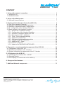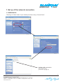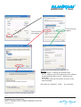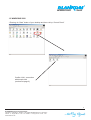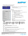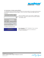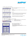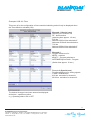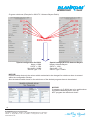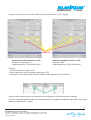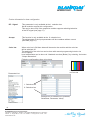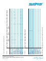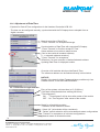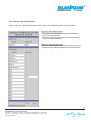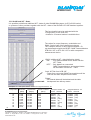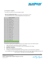
1
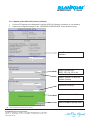
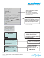
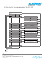
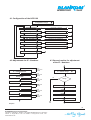
ANTENNENTECHNIK
User - Manual
Headend Controller HCB 100 “blue” (9650.05)
Changes due to technical progress possible!
BLANKOM Antennentechnik GmbH
Hermann - Petersilge - Straße 1 ·
D-07422 Bad Blankenburg ·
Germany
Phone: ++ 49 (0) 36 74 1 / 60 - 0 ·
Telefax: ++ 49 (0) 36 74 1 / 60 - 100
www.blankom.de
GmbH
ANTENNENTECHNIK
GmbH
CONTENT
1. Set up of the network connection............................................................................. 3
1.1 WINDOWS XP ......................................................................................................... 3
1.2 WINDOWS 2000 ...................................................................................................... 5
2. Set up of the Web browser ........................................................................................ 7
2.1 Microsoft Internet Explorer ....................................................................................... 7
3. Working with the Headend Controller (HCB 100)....................................................
3.1 Call up the Headend Controller ...............................................................................
3.2 Selection of the desired Headend overview.............................................................
3.3 Selection of Adjustments and Configurations...........................................................
3.4 IP - configuration of the Headend Controller............................................................
3.5 Basic settings of the Headend Controller ................................................................
3.5.1 Reset of the Headend Controller ....................................................................
3.5.2 Configuration of the Headend Controller .........................................................
3.5.3 Activation of Software Option HCB 100 ...........................................................
3.5.4 Manual start of NIT - distribution .....................................................................
3.5.5 Timer / Time controlled switching ....................................................................
3.5.6 Adjustment of Date/Time .................................................................................
3.5.7 Cold start of individual/single modules ............................................................
3.5.8 Change of User ID, Pass word ........................................................................
3.5.9 Additional NIT - Datas ......................................................................................
3.5.10 Protocol / Log book .........................................................................................
3.5.11 Update of the HEAEND CONTROLLER ..........................................................
8
8
10
12
13
14
14
14
15
15
16
22
22
23
24
25
26
4. Diagram for manual operation/management of the HCB 100 ......................
4.1 Configuration of the HCB 100 ..................................................................................
4.2 Adjustment possibilities of IP - Numbers .................................................................
4.3 General Information for adjustments of the IP - Number .........................................
28
29
29
29
5. LCD display at the HCB 100 .....................................................................................
5.1 Initializing of the modules after a RESET ................................................................
5.2 Standard Display .....................................................................................................
5.3 Error display, if a module can not be called up ........................................................
30
30
30
30
6. Changes of the Hardware ......................................................................................... 31
7. Additional Network components ............................................................................. 32
BLANKOM Antennentechnik GmbH
Hermann - Petersilge - Straße 1 ·
D-07422 Bad Blankenburg ·
Germany
Phone: ++ 49 (0) 36 74 1 / 60 - 0 ·
Telefax: ++ 49 (0) 36 74 1 / 60 - 100
www.blankom.de
ANTENNENTECHNIK
GmbH
1. Set up of the network connection
1.1 WINDOWS XP
- Entering via “Start” button of your desktop and then call up “Control Panel”
Confirm LAN - connection
with douple click
(continue at page 4)
3
BLANKOM Antennentechnik GmbH
Hermann - Petersilge - Straße 1 ·
D-07422 Bad Blankenburg ·
Germany
Phone: ++ 49 (0) 36 74 1 / 60 - 0 ·
Telefax: ++ 49 (0) 36 74 1 / 60 - 100
www.blankom.de
ANTENNENTECHNIK
TCP/IP Protocol
not installed
GmbH
TCP/IP Protocol
installed
Select “Use the following IP address”!!!
NOTICE
- Enter a valid IP - Address and Subnet mask.
- The IP - Address of the PC/Laptop has to be different
(Least Significant Bit) of the IP - Address of the
HCB 100.
- The Subnet mask can be entered as shown in the
above example.
NO entries for “Gateway”, “DNS” ... are necessary.
Select Protocol (TCP/IP) and then press OK
4
BLANKOM Antennentechnik GmbH
Hermann - Petersilge - Straße 1 ·
D-07422 Bad Blankenburg ·
Germany
Phone: ++ 49 (0) 36 74 1 / 60 - 0 ·
Telefax: ++ 49 (0) 36 74 1 / 60 - 100
www.blankom.de
ANTENNENTECHNIK
GmbH
1.2 WINDOWS 2000
- Entering via “Start” button of your desktop and then call up “Control Panel”
Confirm LAN - connection
with douple click
(continue at page 6)
5
BLANKOM Antennentechnik GmbH
Hermann - Petersilge - Straße 1 ·
D-07422 Bad Blankenburg ·
Germany
Phone: ++ 49 (0) 36 74 1 / 60 - 0 ·
Telefax: ++ 49 (0) 36 74 1 / 60 - 100
www.blankom.de
ANTENNENTECHNIK
TCP/IP Protocol
NOT installed
GmbH
TCP/IP Protocol
installed
Select “Use the following IP address”!!!
NOTICE
- Enter a valid IP - Address and Subnet mask.
- The IP - Address of the PC/Laptop has to be different
(Least Significant Bit) of the IP - Address of the
HCB 100.
- The Subnet mask can be entered as shown in the
above example.
NO entries for “Gateway”, “DNS” ...necessary.
Select Protocol (TCP/IP) and then press OK
6
BLANKOM Antennentechnik GmbH
Hermann - Petersilge - Straße 1 ·
D-07422 Bad Blankenburg ·
Germany
Phone: ++ 49 (0) 36 74 1 / 60 - 0 ·
Telefax: ++ 49 (0) 36 74 1 / 60 - 100
www.blankom.de
ANTENNENTECHNIK
GmbH
2. Set up of the Webbrowser
2.1 Microsoft Internet Explorer
- Open the Webbrowser (MS Internet Explorer), select “Tools” and then “Internet Options ...”
Press “General” and “Settings”
Press “Connections”
Select “Never dial a
connection”
Select “Every visit to the page” !!!
Notice
To avoid display errors please change the
adjustments for the storing of temporary
Internet files.
Please disconnect the access to a Proxyserver
for direct connection of the HCB 100 with
PC/Laptop.
Please restart the PC/Laptop after all settings/adjustments are finished.
Then the connection to the Headend Controller HCB 100 can be called up via the Webbrowser.
7
BLANKOM Antennentechnik GmbH
Hermann - Petersilge - Straße 1 ·
D-07422 Bad Blankenburg ·
Germany
Phone: ++ 49 (0) 36 74 1 / 60 - 0 ·
Telefax: ++ 49 (0) 36 74 1 / 60 - 100
www.blankom.de
ANTENNENTECHNIK
GmbH
3. Working with the Headend Controller HCB 100
3.1 Access to the Headend Controller
Enter the IP - Number into the address - line.
(IP - Number ex works BLANKOM is always: 192.168.2.80)
The Login - window of the HCB 100 will be displayed if all adjustments/settings are correct.
You now can save/secure the operation via a password.
Selecting the configuration “Automatic Login” allows Login without password entry (see 3.5.2).
8
ANTENNENTECHNIK
GmbH
Enter USER ID and Password
USER ID and Password ex works BLANKOM:
User ID.......0000
Password....0000
Writing protection has been deleted.
You will be automatically forwarded to the
“Selcetion - Menu”.
Selection of desired Headend overview table
(see 3.2)
Selection of Adjustments and Configurations
(see 3.3)
9
BLANKOM Antennentechnik GmbH
Hermann - Petersilge - Straße 1 ·
D-07422 Bad Blankenburg ·
Germany
Phone: ++ 49 (0) 36 74 1 / 60 - 0 ·
Telefax: ++ 49 (0) 36 74 1 / 60 - 100
www.blankom.de
ANTENNENTECHNIK
GmbH
3.2 Selection of the desired Headend overview table
Headend overview (LIST)
The Headend overview (List) displays all the modules of the
entire Headend system as a List.
Selecting the button “Edit” gets you to the operation overview
of the respective module.
Headend overview table (Matrix)
The Headend overview (Matrix) displays all the modules of the entire Headend system as a Matrix.
- The first line (horizontaly / here 02 and 03) displays the line-addresses of the Power supply (BEB 100).
- The fist line (verticaly / here 01 - 07) displays the addresses of the individual modules, as well as
additional information like the module type, the synchronisation (SYNC) for digital converters, channel
name(s), respective output band and -frequencies...
Selecting the button “Edit” gets you to the operation overview of the respective module.
10
BLANKOM Antennentechnik GmbH
Hermann - Petersilge - Straße 1 ·
D-07422 Bad Blankenburg ·
Germany
Phone: ++ 49 (0) 36 74 1 / 60 - 0 ·
Telefax: ++ 49 (0) 36 74 1 / 60 - 100
www.blankom.de
ANTENNENTECHNIK
GmbH
Headend overview table (Button)
The Headend overview table (Button) displays all the modules of the
entire Headend system with various configurtion buttons.
Following functions can be selected:
The user interface of the respective module is open and it is possible to make
“Edit”
adjustments.
“Copy (data page)”
The “Copy (data page)” of the desired module will be processed. It displays
all adjusted parameters and can be saved/stored.
(Store/save within Internet Explorer: “Data/File” ®
“Save target at/as”)
The menu “All” enables the processing of a copy/data page for the entire
Headend system.
NOTICE:
The “Copies/data pages” will be stored/saved with a new forma and are NOT
downwards compatible. These can not be used with the HCB 100 module types
(9650.01 / 9650.02).
“ON / OFF”
A menu with “ON”, “OFF” or “RESET” will be displayed
- Selecting “ON” or “OFF” allows you to change the operation status of the
desired module
- Selecting “RESET” will disconnect/switch off the desired module for 8 seconds.
“Ouput attenuation”
Selecting “Output attenuation” enables you to change the output level of the
desired module.
“Status”
The operating status of the desired module will be called up and displayed.
- Selecting the button “Headend read out” effects a scan of the entire Headend system including all
connected modules.
- Selecting the button “check-out” occurs an automatic log out of the headend system
- Selecting the button “Selection” gets you to the selection menu of the headend system.
11
BLANKOM Antennentechnik GmbH
Hermann - Petersilge - Straße 1 ·
D-07422 Bad Blankenburg ·
Germany
Phone: ++ 49 (0) 36 74 1 / 60 - 0 ·
Telefax: ++ 49 (0) 36 74 1 / 60 - 100
www.blankom.de
ANTENNENTECHNIK
GmbH
3.3 Selcection of Adjustments and Configurations
Headend level settings (List)
Module information (Matrix)
The Matrix overview displays the part n°,
current software and the serial n° of the respective
module.
For adjustment/setting of signal-level
for each module of the headend
enter “Transmit” to confirm desired/selected
level.
Headend Controller
- Displays all setting/adjustment opportunities of the
entire headend or for individual modules.
- Displays the IP - number, the current software of the
Headend Controller HCB 100. Setting/adjustment of the
IP - informations in part 3.4.
- Basic settings/adjustments in part 3.5
- The button “Name” allows to print a desired name for the
headend.
- The button “Language” allows the selection between
German & English.
12
BLANKOM Antennentechnik GmbH
Hermann - Petersilge - Straße 1 ·
D-07422 Bad Blankenburg ·
Germany
Phone: ++ 49 (0) 36 74 1 / 60 - 0 ·
Telefax: ++ 49 (0) 36 74 1 / 60 - 100
www.blankom.de
ANTENNENTECHNIK
GmbH
3.4 IP - Configuration of the Headend Controller
Access the sub-menu by double-click to
“IP-Number”.
Additional functions for the IP-configuration of the
Headend Controller will be activated.
a
“IP number”
- Enter current IP - address of the HCB 100
a
“Subnet mask”
- Enter Subnet mask
a
“Gateway address”
- Enter Gateway Address of the available network
a
“DHCP address”
- Enter IP - Address for automatic IP - allocation for
Laptop/PC
(Activation “Obtain an IP address automatically” at the PC)
a
“IP number VEA 107”
- Enter IP - Address of connected
Encoder/Multiplexer VEA 107
a
“TRAP address”
- Enter IP - Address for forwarding TRAP - Messages
(Case of error)
a
“IP number NIT rack B”
- Enter IP - Address for exchange of NIT - Datas of 2
HCB 100
13
BLANKOM Antennentechnik GmbH
Hermann - Petersilge - Straße 1 ·
D-07422 Bad Blankenburg ·
Germany
Phone: ++ 49 (0) 36 74 1 / 60 - 0 ·
Telefax: ++ 49 (0) 36 74 1 / 60 - 100
www.blankom.de
GmbH
ANTENNENTECHNIK
3.5 Basic settings of the Headend Controller
3.5.1 Reset of the HEADEND CONTROLLER
Enter “RESET” effects a restart of the HEADEND CONTROLLER,
- A software reset is done.
- Afterwards a headend read out is done.
3.5.2 Configuration HEADEND CONTROLLER
Sub-Menu for activation of additional functions
for the Headend controller HCB 100.
a
“Address select.” (manual operation)
ON ... Manual selection is done via Up / Down key-pads of the
HCB 100
OFF ... Selection is done via direct entry of
line- and device addresses
a
“All characters” (manal operation)
ON ... Text input for all characters possible
OFF ... Text input only for 0- 9 and A - Z possible
a
“NIT - Distribution”
ON ... NIT - datas will be exchanged dynamically
OFF ... NIT - datas will be switched OFF
a
“NIT - Rack A”
“NIT - Rack B”
Notice:
Special adjustments have to be done when interchanging
NIT - datas of two HCB 100 or one HCB 100 with additional
NIT - datas.
Example:*
HCB 100 with
32 x STB 606**
NIT - Rack A
NIT - Rack B
HCB 100 Rack A with HCB 100 Rack B with
16 x STB 606**
16 x STB 606**
a
a
a
OFF
OFF
EIN
OFF
OFF
ON
“Additional NIT data”
ON ... input of 16 external transponder information possible
OFF ... NO additional inputs possible
a
“Key lock”
ON ... manual settings/adjustments directly at HCB 100 deactivated
OFF ... manual settings/adjustments directly at HCB 100 activated
a
“Automatic Login”
ON ... writing protection is deactivated. Access to the Menu without password entry possible.
OFF ... entry of User ID & Password necessary for access to the menu
A
“Timer / Time part acting”
ON ... time controlled changes/switching is possible/activated
OFF ... time controlled changes/switching deactivated
14
* Max 32 NIT - Datas of the B-LINE - modules can be processed. (16 x Rack A + 16 x Rack B) or (16 x B-LINE + 16 x external)
**Valid for following B-LINE modules: STB 606, STB 607, STB 006, AMB 206, CTB 206
BLANKOM Antennentechnik GmbH
Hermann - Petersilge - Straße 1 ·
D-07422 Bad Blankenburg ·
Germany
Phone: ++ 49 (0) 36 74 1 / 60 - 0 ·
Telefax: ++ 49 (0) 36 74 1 / 60 - 100
www.blankom.de
ANTENNENTECHNIK
GmbH
3.5.3 Activation of software option HCB 100
The Headend Controller HCB 100 (9650.05) enables the implementation of the entire headend system
into a Network-Management-System (NMS). To do so you have to activate the SNMP agent at the
HCB 100.
Enter the activation code for the activation of SNMP agent.
Press button “Transmit” to confirm the code and to activate
the software option.
3.5.4 Manual NIT-Distribution
Press “Start Manual NIT - Distribution” for an one time
NIT - Distribution.
Please, see more detailed information for NIT-Distribution at
our website, www.blankom.de.
15
BLANKOM Antennentechnik GmbH
Hermann - Petersilge - Straße 1 ·
D-07422 Bad Blankenburg ·
Germany
Phone: ++ 49 (0) 36 74 1 / 60 - 0 ·
Telefax: ++ 49 (0) 36 74 1 / 60 - 100
www.blankom.de
ANTENNENTECHNIK
GmbH
3.5.5 Timer / Time controlled switching
Timer / Time controlled switching allows a time controlled
switchover of programs.
NOTICE
Time-synchronization of the HCB100 is done with a reference time
(see 3.5.5).
NOTICE
- Input of parameters/values into the timer has to be done in the
sequence of the operator interface of the respective module
(see page 17 for the sequences of the module)
- Upper and lower cases have as well as the input of the
dimensions (e.G. MHz) have to be considered
“Extended display”
ON ... 2 additional columns for entry of further parameters
parameters will be faded in.
OFF ... additional functions are fade out
Timer / Time controlled switching is OFF
- NO input windows are enabled
- Press “Configuration” to go to the
menu “Configuration for Headend Controller”
- To enable the configuration table, press Timer/Time controlled
switching to “ON”.
16
BLANKOM Antennentechnik GmbH
Hermann - Petersilge - Straße 1 ·
D-07422 Bad Blankenburg ·
Germany
Phone: ++ 49 (0) 36 74 1 / 60 - 0 ·
Telefax: ++ 49 (0) 36 74 1 / 60 - 100
www.blankom.de
ANTENNENTECHNIK
GmbH
Examples HCB 100 Timer
This menu is for the configuration of time controlled switching and will only be displayed when
the Timer-Mode is activated (ON).
Example 1 (Special case)
Switching of 2 modules via
RF - disconnection
(switching time approx. 1-2 sec.)
5:00 hrs.
Address 02/03 will be switched off
Addresse 02/04 will be switched on
7:00 hrs
Address 00/04 will be switched off
Address 00/03 will be switched on
Example 2
Program switchover for
MPEG - modules
KIKA TV - Program switches to
ANTENNE Bayern Radio - Program
(Switch time approx. 10 sec.)
Example 3 (Special case)
Program switchover for analog signals
C-LINE TWIN-Module
8:00 hrs. activation for channel 1
20:00 hrs. activation for channel 2
The desired changes have been entered as displayed
at the html - operation surface.
e. g. Operating status: ON or OFF
17
BLANKOM Antennentechnik GmbH
Hermann - Petersilge - Straße 1 ·
D-07422 Bad Blankenburg ·
Germany
Phone: ++ 49 (0) 36 74 1 / 60 - 0 ·
Telefax: ++ 49 (0) 36 74 1 / 60 - 100
www.blankom.de
ANTENNENTECHNIK
GmbH
Program switchover (Example for KIKA-TV / Antenne Bayern-Radio)
Differences
Special configuration for KIKA:
Name = KIKA
SAT-IF = 1354
ServiceID = 28008
Service Type = TV
Special configuration for Antenne Bayern:
Name= Antenne Bayern
SAT-IF = 1548
ServiceID = 170
Service Type = Radio
NOTICE!
Please consider that only the values which are desired to be changed for switchover have to entered
within the configuration window.
Also the desired switch times for the switchover of the desired programs have to be selected.
NOTICE!
If programs (e.G. KIKA) are to be switchedover
by fixed broadcasting-times, then do
NOT program the switchover time!!!
18
BLANKOM Antennentechnik GmbH
Hermann - Petersilge - Straße 1 ·
D-07422 Bad Blankenburg ·
Germany
Phone: ++ 49 (0) 36 74 1 / 60 - 0 ·
Telefax: ++ 49 (0) 36 74 1 / 60 - 100
www.blankom.de
ANTENNENTECHNIK
GmbH
Program selection for the C-LINE headend system (special case via RF - Signal)
Differences
Switching condition channel 2 “ON”:
Program = Sonnenklar TV
Output frequency = 503,25 MHz (K25)
Switching condition channel 1”ON”:
Program = HSE
Output frequency = 503,25 MHz (K25)
Example
- Currently channel 1 (HSE) is activ
- Output channel for timer controlled switchover is K25
- Sonnenklar-TV will be switched ON and HSE24 will be switched OFF at 20:00 hrs..
Activated channel
Only the active channel has to be selected for this configuration. No further entries necessary.
This time controlled switchover allows to change/switchover programs of different levels within one module
without an additional RF - switch.
19
BLANKOM Antennentechnik GmbH
Hermann - Petersilge - Straße 1 ·
D-07422 Bad Blankenburg ·
Germany
Phone: ++ 49 (0) 36 74 1 / 60 - 0 ·
Telefax: ++ 49 (0) 36 74 1 / 60 - 100
www.blankom.de
ANTENNENTECHNIK
GmbH
Further information for timer configuration
RF - Signal:
This parameter is only available at the 1. selection box.
Not all modules support this configuration.
This can be done only if the respective module supports switching/selection
of the RF-signal (see page 17).
Accept:
This function is only available at the 8. selection box.
The adjustments of the input parameters will be overtaken without a reset
(see tabel page 21).
Color bar:
When color bar is ON then datas will be sent to the module and the color bar
will be switched off.
The switchoff of the color bar can be done with manual programming but also via
via PC/Laptop.
Level adjustments can be done via “Headend overview (Button)” by selecting the button
“Output attenuation”.
Following configurations have to be done.
TV-picture with
color bar ON
Parameter-List
1. Selection box
8. Selection box
Example for an selection box (Address,
Switchtime, Parameter, Value)
20
BLANKOM Antennentechnik GmbH
Hermann - Petersilge - Straße 1 ·
D-07422 Bad Blankenburg ·
Germany
Phone: ++ 49 (0) 36 74 1 / 60 - 0 ·
Telefax: ++ 49 (0) 36 74 1 / 60 - 100
www.blankom.de
BLANKOM Antennentechnik GmbH
Hermann - Petersilge - Straße 1 ·
D-07422 Bad Blankenburg ·
Germany
Phone: ++ 49 (0) 36 74 1 / 60 - 0 ·
Telefax: ++ 49 (0) 36 74 1 / 60 - 100
www.blankom.de
x
x
x
x
x
x
x
x
x
x
x
x
x
x
x
x
x
x
x
x
x
x
x
x
x
x
x
x
x
x
x
x
x
x
x
x
x
x
x
x
x
x
x
x
x
x
x
x
x
x
x
x
x
x
x
x
x
x
x
x
x
x
x
x
x
x
x
x
x
x
x
x
x
x
x
x
x
x
x
x
x
x
x
x
x
x
x
x
x
x
x
x
x
x
x
x
x
x
x
x
x
x
x
CCB 1x1 CTB 1x1 VMB 1x1 ATB 1x1 ADB 109 ADB 209
923x.xx 983x.xx 922x.xx 984x.xx 9861.01 9862.04
TCB xx1
92xx.xx
x
x
x
x
x
TTB 5x1 UCB 1x6
982x.xx 919x.01
TTC 591
9601.xx
STC 191 TCC 591 STC 697 VMC 191 VMC 101 STC 201
9616.xx 9617.xx 9619.02 9627.xx 9627.05 9611.01
x
x
x
x
x
x
STB 1x1 SDB 209 STB 2x1 STB 607
920x.xx 9802.0x 981x.xx 9880.01
STC 291
9609.xx
Bold marked Parameters (x) can be edited via acceptance command!
Channel (only C-LINE)
Name
SAT-IF
QPSK-Symbol rate
Service ID
Language n°
Service type
Adjustment code
SAT-Sound frequency
Input frequency
Spectrum inversion
QAM-Symbol rate
IF-bandwidth
Color bar
Operating status
Accept
RF-Signal
Parameter
Channel (only C-LINE)
Name
SAT-IF
QPSK-Symbol rate
Service ID
Language n°
Service type
Adjustment code
SAT-Sound frequency
Input frequency
Spectrum inversion
QAM-Symbol rate
IF-bandwidth
Color bar
Opberating status
Accept
RF signal
Parameter
Possible parameters for timer controlled switchover
ANTENNENTECHNIK
GmbH
21
ANTENNENTECHNIK
GmbH
3.5.6 Adjustment of Date/Time
3 Options for Date & Time configuration via the Headend Controller HCB 100.
- The time can be configured manually, synchronised with the PC/Laptop-time or adopted from an
digital converter
Manual correction of Date/Time
- Press “Transmit” for acceptance/storage
Synchronization of Date/Time with connected PC/Laptop
- Press “Transmit” to Confirm accept PC-Time ”
Select address of a module to adopt its time
(Can be done with all headend modules)
[-/- = automatic address selection]
- Press “Transmit” for acceptance
Offset time, for time correction of desired/selected address
Updating Date/Time for displayed module
Overview of all modules which provide Date & Time.
The reference address can be selected directly in this window
NOTICE!
Display of the date for digital Transmodulators possible only from
sofware-version V1.68 of the MPEG-Module.
3.5.7 Cold start of single modules
Entry of the sytstem cold start time (e.G. 03:00 hrs.)
(Cold start is deactivated when entering 00:00 hrs.)
“Time alignment”*
ON ... “Time aligment” will be done after restart of the module
OFF ... No “Time aligment” after restart of the module
Matrix for all available modules
- Selection of the module for restart
- Select “All” (all modules will be considered)
- “Delete” module-selection will be relocated and restart configurations
- “Transmit” for acceptance of cold start configurations
- Manual restart of selected/modules
22
BLANKOM Antennentechnik GmbH
Hermann - Petersilge - Straße 1 ·
D-07422 Bad Blankenburg ·
Germany
Phone: ++ 49 (0) 36 74 1 / 60 - 0 ·
Telefax: ++ 49 (0) 36 74 1 / 60 - 100
www.blankom.de
ANTENNENTECHNIK
GmbH
3.5.8 Change User ID, Password
Access rights for 1 Main-Administrator and for up to 15 Sub-adminsitrators can be edited!!!
Rights for Main-Administrator
- Full rights for configuration/management/changes
for the headend system
- To provide and to change User Id´s and Passwords
for the Sub-Administrators
Rights for Sub-Administrators
- The Sub-Adminsitrators only have the right to do any
changes/configuration/management of the headend
23
BLANKOM Antennentechnik GmbH
Hermann - Petersilge - Straße 1 ·
D-07422 Bad Blankenburg ·
Germany
Phone: ++ 49 (0) 36 74 1 / 60 - 0 ·
Telefax: ++ 49 (0) 36 74 1 / 60 - 100
www.blankom.de
ANTENNENTECHNIK
GmbH
3.5.9 Additional NIT - Datas
It is possible to distribute additional NIT - datas of other BLANKOM systems (e.G Profi-800 series)
or systems of other providers togehter with the NIT - datas of the B-LINE & C-LINE headend systems.
This functionality has to be activated with the
“Configuration” of the HCB 100.
- A table for 32 manual entries is available then.
The values for output frequency, modulation and
QAM - Symbol rate of the channels are known.
The Transport stream- ID and Original Network - ID
can be determined with the QPSK / QAM Transmodulators
STB 606 / 607 or STC 696 / 697 or with a respective
measurement device.
“ONLY“ additional NIT - data distribution (static)
“ON” ... Only entered datas will be written into the
NIT - Table
“OFF” ... Only datas from connected
QAM-Transmodulators and entered datas
will be written into the NIT - Table
“Load NIT file from HCB 100”
- Datas from connected QAM-Transmodultors will be
read out and then adopted into the table
“Delete”
- All entered datas will be deleted and the table
backspaced into delivery status
Examples of a Transport stream - ID and an original Network - ID
Transponder
24
65
67
69
71
75
77
81
83
85
Downlink
(MHz)
Symbol rate
(Msps)
SAT-IF / L-Band
(MHz)
Transport stream - ID
Hexal Decimal
Original-Network - ID
Hexal Decimal
11720
11758
11798
11836
11914
11954
12032
12070
12110
27,500
27,500
27,500
27,500
27,500
27,500
27,500
27,500
27,500
1120
1158
1198
1236
1314
1354
1432
1470
1510
0x0003
0x0011
0x0002
0x044D
0x0006
0x0437
0x0004
0x0005
0x0431
0x0085
0x0085
0x0085
0x0001
0x0085
0x0001
0x0085
0x0085
0x0001
BLANKOM Antennentechnik GmbH
Hermann - Petersilge - Straße 1 ·
D-07422 Bad Blankenburg ·
Germany
Phone: ++ 49 (0) 36 74 1 / 60 - 0 ·
Telefax: ++ 49 (0) 36 74 1 / 60 - 100
www.blankom.de
(3)
(17)
(2)
(1101)
(6)
(1079)
(4)
(5)
(1073)
(133)
(133)
(133)
(1)
(133)
(1)
(133)
(133)
(1)
ANTENNENTECHNIK
GmbH
3.5.10 Protocol / Logbook
The HCB 100 contains of a Protocol/Logbook system
- Up to 127 events can be stored
- Every entry displays date, time and information of the respective events.
(The latest/last input/entry is always displayed above the green line)
The Protocoll registers/stores different accesses and its related events to the headend system:
1.
2.
3.
4.
5.
6.
Logon and Logoff via the Browser (User ID / Password)
Changes of the maximum- and minimum values for temperature and voltage
Activation of the Timer
Start of NIT - distribution
Reset of the Headend controller HCB 100
Changing of adjustments/configurations (Writing protecton to the module will be registered)
ALL CHANGES WILL BE STORED AND DISPLAYED WITH DATE AND TIME INFORMATION ONLY IF
THE CLOCK OF THE HCB 100 IS SYNCHRONIZED
25
BLANKOM Antennentechnik GmbH
Hermann - Petersilge - Straße 1 ·
D-07422 Bad Blankenburg ·
Germany
Phone: ++ 49 (0) 36 74 1 / 60 - 0 ·
Telefax: ++ 49 (0) 36 74 1 / 60 - 100
www.blankom.de
ANTENNENTECHNIK
GmbH
3.5.11 Update of the HCB 100 (internal software)
1.
2.
Connect PC/Laptop to the Headend Controller HCB 100 (directly connection or via network)
Select the configuration page for the “HEADEND CONTROLLER” at the selection menu
Load Datas (values) or
software
Sample headend station
Search
Select Upload files*
HCB_100_Up_V3.xx.txt
Select “Upload” to start the
update function
Search
Upload is running!!!
Upload was successful!
Start software-update then!
26
* The upload/update file has to be stored as .txt file at the PC/Laptop.
NO zip - data/file can be stored with the HCB 100.
BLANKOM Antennentechnik GmbH
Hermann - Petersilge - Straße 1 ·
D-07422 Bad Blankenburg ·
Germany
Phone: ++ 49 (0) 36 74 1 / 60 - 0 ·
Telefax: ++ 49 (0) 36 74 1 / 60 - 100
www.blankom.de
ANTENNENTECHNIK
GmbH
Display for all versions available
with this update.
The connection circuit board
(APL) versions will be actualized
automatically also
Start software update
- Duration for HCB 100 update approx 2 Min.
- Disconnect a possible ethernet-connection
before starting the update and during upd.
- Duration for the APL update
approx. 15 sec./per module
*)
*) - Firmware-Updates for the modules can much more longer
(Advice HCB: Software update)
Feedback: Start Software update
Bootloader
- Updates runs automatically
!!! NO access to the HCB 100 during
the update possible!!!
BLANKOM
Antennentechnik GmbH
Updates runs automatically
Softwareupdate
BLANKOM
Antennentechnik GmbH
Update is finished when
ENTER and the TIME is
displayed at the HCB 100
®
END of Update
ENTER
13:01
27
BLANKOM Antennentechnik GmbH
Hermann - Petersilge - Straße 1 ·
D-07422 Bad Blankenburg ·
Germany
Phone: ++ 49 (0) 36 74 1 / 60 - 0 ·
Telefax: ++ 49 (0) 36 74 1 / 60 - 100
www.blankom.de
GmbH
ANTENNENTECHNIK
4. Flow-chart for manual operation of the HCB 100
BLANKOM
ENTER
Ú
Select module address
Modules/Cassettes
Ú
Type / Part N°
Ú
OK
Change Module
Ú
Ú
NIT - Distribution
(see device manual of respective module)
Displays
NIT-Verteilung execution
Displays
Temperature
Displays
Voltage
Displays
Current
Any key
Ú
Ú
Temperature
Any key
Ú
Any key
Voltage
Ú
Any key
Current
Ú
Ú
Change configuration
Configuration
Ú
1
11
Ú
Contrast Ú
Displays/Selection
Version
Ú
Displays
Reset
Ú
+/-
Ú
Any key
Version
Ú
System reset
Ú
IP - NumberÚ
Ú
Back
Ú
ENTER
Up
Ú
Down
Ú
28
BLANKOM Antennentechnik GmbH
Hermann - Petersilge - Straße 1 ·
D-07422 Bad Blankenburg ·
Germany
Phone: ++ 49 (0) 36 74 1 / 60 - 0 ·
Telefax: ++ 49 (0) 36 74 1 / 60 - 100
www.blankom.de
Change IP - Number
2
21
GmbH
ANTENNENTECHNIK
4.1 Configuration of the HCB 100
Configuration change
1
1
Ú
Address selection
Direct input or selection
Ú
Ú
All signs
All or numbers and capital letters
Ú
Ú
Matrixview
Module overview as list or matrix
NIT - distribution
Implement or do not implement
Ú
Ú
Ú
Ú
NIT - Rack A
1. HCB 100 in the NIT - Data exchange
NIT - Rack B
2. HCB 100 in the NIT - Data exchange
Ú
Ú
Ú
End
Ú
Ú
11
4.2 Adjustments for IP - Numbers
4.3 General routine for adjustment
of the IP - Numbers
2
IP - number Webserver
xx or zz
(see fig. on the
right side)
IP - number change
2
xx or zz
(see fig. on the
right side)
Subnet Mask
NO
xx or zz
(see fig. on the
right side)
Gateway
Change
JA
xx or zz
(see fig. on the
right side)
DHCP - IP
xx or zz
(see fig. on the
right side)
VEA - IP
Trap - IP (SNMP)
4. Byte (MSB)
*
3. Byte
2. Byte
xx or zz
(see fig. on the
right side)
1. Byte (LSB)
21
21
21
* Option
29
BLANKOM Antennentechnik GmbH
Hermann - Petersilge - Straße 1 ·
D-07422 Bad Blankenburg ·
Germany
Phone: ++ 49 (0) 36 74 1 / 60 - 0 ·
Telefax: ++ 49 (0) 36 74 1 / 60 - 100
www.blankom.de
ANTENNENTECHNIK
GmbH
5. LCD Display at the Headend Controller HCB 100
Start ...
V3.02 / 19.08.06
Start of the HCB 100
==> Current software version of HCB 100 is displayed
IP-Number
Power ON RESET occurs an additional running-time
for the self initialization of the modules
Start ...
V2.22 / 20.04.06
Wait . . . . . .
8s
5.1 Initialization of the modules after a RESET
Search. . .
BUS-Extender
BEB 100
ADDR 05
-----------------
Search for BUS-Extenders BEB 100
==> Displays all found BEB 100
Search. . .
BUS-Extender
BEB 100
ADDR 05
12345 - - - - - - - - - - - -
Search for BUS - Extenders BEB 100 is finished
==> Displays the found BEB 100 with respective addresses
(here 1, 2, 3, 4 und 5 = 5 BEB 100 are founded)
Search. . .
BEB 100
ADDR 02
Module
ADDR 04
-----------------
Search for modules of line 2
==> Displays all found modules
Search. . .
BEB 100
ADDR 02
Modules
ADDR - 12345 - - - - - - - - - ----
Search for modules of line 2 is finished
=> Displays the found BEB 100 with respective addresses
5.2 Standard Display
Suche. . .
BEB 100
BEB 100
Enter
ADDR 02
ADDR - 15:23
Suche. . .
BEB 100
ADDR 02
BEB 100
ADDR - NIT - Verteilung
HCB 100 is in operation mode (works correctly)
==> Green LED is on.
HCB 100 is doing a data exchange between QSPK/QAM-Modules
==> Yellow Led is “blinking”
5.3 Display of Errors, if a module is not supported
HCB 100 tried to detect a module which is not supported.
TTT TTT
11111
ZZZZ . ZZ
22222
Software update!
Press any key
11111
TTT TTT
22222
ZZZZ.ZZ
30
BLANKOM Antennentechnik GmbH
Hermann - Petersilge - Straße 1 ·
D-07422 Bad Blankenburg ·
Germany
Phone: ++ 49 (0) 36 74 1 / 60 - 0 ·
Telefax: ++ 49 (0) 36 74 1 / 60 - 100
www.blankom.de
Index of the module
recognized Type
Index of theHCB 100 read out
drawing number
ANTENNENTECHNIK
GmbH
6. Change of hardware (remove, ad or change modules)
The internal memory of the HCB 100 assures a backup (Copy) of the headend configuration.
If a module will be changed/removed or a new one will be added then the HCB 100 has to reload this new
hardware
Press “Headend read out”
==> New/changed configuraiton will be scanned (new scan)
NOTICE
No communication/access to the HCB 100 possible
The selection menu is available afterr successful scan is finished
INFORMATION
A Reset/Restart can be done within the menu of the Headend Controller or at the HCB 100 directly.
==> The headend will also be scanned then
31
BLANKOM Antennentechnik GmbH
Hermann - Petersilge - Straße 1 ·
D-07422 Bad Blankenburg ·
Germany
Phone: ++ 49 (0) 36 74 1 / 60 - 0 ·
Telefax: ++ 49 (0) 36 74 1 / 60 - 100
www.blankom.de
ANTENNENTECHNIK
7. Additional network components
Interconnection of several Headend Controllers HCB 100 and combination with
different activations:
- At site operation/management/adjustment with PC/Laptop
(Direct connection between PC/Laptop and HCB 100)
- Remote control/management via Ethernet
- Remote control via Router (ISDN, Modem, WLAN)
Connection to one or more HCB 100 directly with PC/Laptop
Laptop
or Ethernet
HCB 100
IP-Number 1
IP-Number 2
1. HCB 100
IP-Number 2
Laptop
or Ethernet
2. HCB 100
HUB / SWITCH
IP-Number 3
IP-Number 1
3. HCB 100
IP-Number 4
Connection to HCB 100 with PC/ Laptop via WLAN
Laptop
WLAN
card
Ad-hoc
IP-Number 1
Wireless
Access Point
IP-Number 2
1. HCB 100
IP-Number 3
Connection to HCB 100 with PC/ Laptop via ISDN - Router
ISDN
HCB 100
ISDN-Router
IP-Number 1
ISDN
ISDN-Router
IP-Number 2
HUB / SWITCH
1. HCB 100
e.G. X1000 von Bintec
IP-Number 1
at 2. and 3. HCB 100
IP-Number 3 und 4
32
BLANKOM Antennentechnik GmbH
Hermann - Petersilge - Straße 1 ·
D-07422 Bad Blankenburg ·
Germany
Phone: ++ 49 (0) 36 74 1 / 60 - 0 ·
Telefax: ++ 49 (0) 36 74 1 / 60 - 100
www.blankom.de
IP-Number 2
GmbH
ANTENNENTECHNIK
GmbH
Connection to HCB 100 via an analogue - Router
analogue
Telephone
connection
analogue
Telephone
connection
Router with
integrated
Modem
HCB 100
IP-Number 1
IP-Number 2
Router with
integrated
Moddem
HUB / SWITCH
IP-Number 1
Example: Prestige 100 MH from ZyXEL
at 2. and 3. HCB 100
IP-Number 3 and 4
1. HCB 100
IP-Number 2
Network of several HCB 100
- At site Control/Management/Adjustments
- REMOTE Control/Management/Adjustments via network connection
- REMOTE Control/Management/Adjustments via Router
Laptop
1. HCB 100
IP-Number 2
Ethernet
(LAN / WAN)
HUB / SWITCH
with minimum
6 Port´s
2. HCB 100
IP-Number 3
ISDN
ISDN-Router
3. HCB 100
IP-Number 4
33
BLANKOM Antennentechnik GmbH
Hermann - Petersilge - Straße 1 ·
D-07422 Bad Blankenburg ·
Germany
Phone: ++ 49 (0) 36 74 1 / 60 - 0 ·
Telefax: ++ 49 (0) 36 74 1 / 60 - 100
www.blankom.de