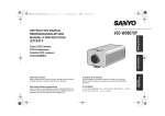
1
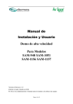
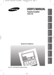
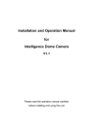
HD-SDI High Speed Dome Camera Series USER’S MANUAL Note: ※Please read the operation manual carefully before installing and using this unit 1 Warning: To reduce the risk of fire or electric shock, do not expose this product to rain or moisture. Do not insert any metallic objects through the bentilation grills or other openings on the equipment. This symbol indicates that dangerous voltage constituting a risk of electric shock is present within this unit. CAUTION: TO REDUCE THE RISK OF ELECTROIC SHOCK, DO NOT REMOVE COVER(OR BACK). NO USER SERVICEABLE PARTS INSIDE. REFER SERVICING TO QUALIFIED SERVICE PERSONNEL 2 Content Warning .......................................................................................... Error! Bookmark not defined. Content ........................................................................................... Error! Bookmark not defined. 1.Points for attention ....................................................................... Error! Bookmark not defined. 2.Function Description .................................................................... Error! Bookmark not defined. 3.System Connection ..................................................................................................................... 6 4.Installation ................................................................................................................................... 7 5.Operation Introduction ................................................................. Error! Bookmark not defined. 6.Technicial data ........................................................................................................................... 23 7.Troubleshooting ........................................................................... Error! Bookmark not defined. Appendix I: Lightning proof and surge signal proof......................... Error! Bookmark not defined. Appendix II: The cleaning of clear downdover ................................ Error! Bookmark not defined. Appendix III: RS485 bus basic knowledge ................................................................................... 26 I. Points for Attention 3 1. Please read the operation manual carefully before installing and operating the product. 2. The product takes power supply of AC24V. The rated input voltage of the camera is marked on the base or other corresponding place. 3. During the course of transportation, storage and installation, the product should be avoided from incorrect operations such as heavy pressing, strong vibration etc., which can cause damage of product as there are sophisticated optical and electronic devices inside the machine. 4. Do not attempt to disassemble the camera. In order to prevent electric shock, do not remove screws or covers. There are no user-serviceable parts inside. 5. Always follow all electrical standards for safety when it is in operation. Adopt the particular power supply which is provided with the unit. RS-485 and video signal should keep enough distance with high voltage equipments and cables when they are in transmission. Precautions for anti-lightning and anti-surging should be taken if necessary. 6. Do not operate it in case temperature, humidity and power supply are beyond the limited stipulations. 7. Do not let the camera aim at the sun or the object with extreme light whatsoever it is switched on or not. Do not let the camera aim at or monitor bright and standstill object for a long time. 8. Do not use aggressive detergent to clean the main body of the camera. Wipe dirt with dry cloth. If needed, mild detergent can be used suitably. 9. Operate the intelligent speed dome camera with great care to avoid shock or vibration. It operate incorrectly, the Speed Dome could be damaged 10. Be careful to avoid to crash, Never mount the unit on a ceiling that cannot support its weight. 11. If necessary, use a commercial lens cleaning paper to clear the lens windows. Gently wipe the lens window until clean. 4 II. Functions Description 1. Integrated speed-variable PAN/TILT a. Turning 360°horizontally and continuously with unlimited positions and an adjustable speed from 0 -- 300°/s; turning 0 - 90°vertically with a speed up to 120°/s. b. Running stably at low speed with super lower noise. Pictures have no shaking. c. the location precision up to ±0.1°. d. 6 programmable tracks, 4 scanning tracks,1 pattern track. e. Idle ptorection and power-off memory function. f. Display orientation,title of speed dome camera,temperature, alarm and other informations 2. High Intelligent Degree a. 255 preset positions can be preset with powerless memory; b. The camera can scan horizontally between two points and scan speed can be modified. The positions of linear scan are optional and the dome camera can scan the range larger or smaller than 180° between any two points with adjustable speed; c. Automatic speed matching function d. Built-in PELCO-D、PELCO-P protocol, baud rate from 2400bps to 19200bps 3. Functions of the Camera a. Description of the Focus Control Mode: the user can adjust the focus of the camera manually. b. Description of Backlight Compensation: when the object to be shot is dark and looks dim, the user can open the backlight compensation according to actual need. c. Description of White Balance: when the image has color distort on the screen, the user can set different modes by orders. There are 6modes for options: Indoor Mode Outdoor Mode Touch Mode Automatic Trace of White Balance ATW Manual WB-MAN Automatic Mode. d. Description of ZOOM Control: user can “pull near” or “push far” the lens according to actual conditions e. Electron shutter: it is 1/50 sec after the camera electrified, and it will display 50 on the monitor. f. AE Mode: setup of Manual/Automatic. g. Low illumination set: It is used only when the external brightness is extremely low. Normally the camera works on the automatic state. In case the external brightness is lower than 1Lux, the camera can be switch to the Zero Illuminance state automatically and icon appears on the screen. You can also set the Zero Illuminance state manually 5 III. System connection Fig 1 6 IV.Installation 1.Conect description 1.1 4 kinds of bracket installation for outdoor speed dome:wall mount, cornet mount, ceilling mount, pole mount. 1.1.1 Wall mount Check the wall and make sure it’s firm. The bearing weight is more than 8 times of the speed dome weight. a. Label installation position b. Install the bracket c. Assemble the speed dome d. Fix the speed dome e. Connection of cables 7 1.1.2 Corner mount Check the wall and make sure it’s firm. The bearing weight is more than 8 times of the speed dome weight. f. Label installation position a. Install the base Make the power cable, RS485 cable and video cable through the hole of base g. Install the bracket b. The same way of wall mount installation 1.1.3 Pole mount The diameter of pillar is 130-150mm( 5.12”~6) a. Install the base b. Install the bracket c. The same way of wall mount installation 1.1.4 Ceilling mount If the ceiling is too low, we can install the speed dome on the base directly. a. Label installation position c. Installation the base 팔 b. Make the cable through the hole and fix the base on the ceilling. Note: if install outdoor, please coat silicone gel on the base. d. Install the bracket d. Install the dome housing Note:if outdoor, please use silicone gel and rubber belt Note, if outdoor, please use waterproof tapes, if the ceilling is too low, we may install on the base directly. e. Connection of cables According to the connection identifier 1.2. Installation for indoor speed dome. 1.2.1 Carefully read the operation manual and the point for attention. 1.2.2 Carefully set the communication code, baud rate and address of the high speed dome camera and make confirmation they are correct. 구 1.2.3 Take out the plug of the dome camera and connect external power supply, RS485 and VF wires as per marks on the plug. Take care that the power supply of the spherical camera and adopt the particular power supply which is provided with the dome camera. 1.2.4 Take out the mounting base from the spherical camera, thread the connecting wire from behind through the central hole of the base. Fix the base by three screws on the ceiling as per the drawing, and connect the wire with the ball. Aim the latch in the ball with the notch on the base as per the drawing, and mount the ball upward to the position and turn it clockwise until the spring sheet on the base takes effect. In case the wire could not come out from behind the ceiling, you can open a hole on the edge of the casing for running of the wire. 이 2.Product size Fig 4.1 3.Connection identifier Fig 4.2 10 V. Operation Introduction 1. Basic Operation of the Menu 1.1 Open the main menu of the setup by the keyboard or the matrix via the operation “Call No. 64 preset position 1.2 When the menu is displayed on the screen, operate “TILT UP”, “TILT DOWN” to move the cursor to the option to be set, operate “PAN LEFT”, “PAN RIGHT” to modify the content or the order to enter this option. 1.3 All setups on the menu couldn’t be lost even power failure 2. Setup of the Menu 1. 1.1 MAIN MENU 1.1.1 SYSTEM SETUP. 1.1.2 DISPLAY SETUP: to enter the submenu of display of the screen by which ID display, title display of preset point and display of MAINMENU camera screen can be set. 1.1.3 CAMERA SETUP: to enter the submenu of setup of normal data of camera. 1.1.4 MOTTON SETUP: to enter the setup of enhanced function of 1.<SYSTEM SETUP> 2.<DISPLAY SETUP> 3.<CAMERA SETUP> 4.<MOTION SETUP> 5.<PRIVACY MSK> 6.<ADVANCE SETUP> 7.SYSTEM RESET 8.EXIT dome camera. 1.1.5 PRIVACY MASK: to enter the submenu of the camera privacy function setting. 1.1.6 ADVANCE SETUP. 1.1.7 SYSTEM RESET: to reset the system. The dome will make self-checking function after it carries out reset function, the station for the dome's reset is : AUTO FLIP -ON/PTZ SPD RATE-ON/ ID DISPLAY-ON/ANGLE DISPLAY-OFF/ DOME LABEL DISPLAY-OFF/ D-ZOOM-OFF/ PT INTERLOCK –AF AUTO/BLC-OFF/ AUTO HOME –OFF/ PARK TIME -4MIN/FAN-AUTO/ TIMP DISPAY-OFF。 11 1.1.8 EXIT: to quit the main menu. 1.2 SYSTEM SETUP 1.2.1 SYSTEM INFORMATION: to display the system information. 1.2.2 AUTO FLIP: to ON/OFF the dome 180°auto flip. 1.2.3 PROP PAN SPD: to ON/OFF the proportional pan function. SYSTEM SETUP 1.SYSTEM INFORMATION 2.AUTO FLIP: ON 3.PROP PAN SPD: ON 4.RESERVED: N/A 5.<ALARM SETUP> 6.RETURN 1.2.4 RESERVED:This function setting also kept for this products. 1.2.5 ALARM SETUP: 1.2.5.1 ALARM NO: N/A 1.2.5.2 ACTION: N/A 1.2.5.3 ALARM: 1.2.5.4 RETURN: to return to the SYSTEM SETUP menu. N/A SYSTEM SETUP 1.SYSTEM INFORMATION 2.AUTO FLIP: ON 3.PROP PAN SPD: ON 4.RESERVED: N/A 5.<ALARM SETUP> 6.RETURN 1.2.6 RETURN: to return to the main menu. 1.3 DISPLAY SETUP 1.3.1 CAMERA ID: when it is set at ON, address of dome camera appears on the screen such as “CAM 001”. The default setting is ON. 1.3.1.1 DISPLAY: to ON/OFF the dome address. 1.3.1.2 POSITION: to set the position of dome address, there are four positions to be displayed: TOP-L (top-left corner), TOP-R (top-right corner), BOTT-R (bottom-right corner) AND BOTT-L (bottom-left corner). 1.3.1.3 RETURN: to return to the DISPLAY SETUP menu. 1.3.2 ANGLE DISPLAY: to enter the angel display submenu. 1.3.2.1 DISPLAY: to ON/OFF the angle display. ONEPUSH singly displayed, auto disappeared in 4 seconds. 1.3.2.2 POSITION: to set the display position of the angle: 12 TOP/BOTTOM. 1.3.2.3 RETURN: to return to the DISPLAY SETUP menu. 1.3.3 PRESET LABEL: to enter the PRESET LABEL submenu. 1.3.3.1 DISPLAY: to ON/OFF the display of the preset label. If it is ON, the preset label will be displayed on the left of the monitor when the preset position is setting. 1.3.3.2 POSITION: to set the display position of the preset label: TOP-at the top of the monitor, BOTTON- at the bottom of the monitor. 1.3.3.3 RETURN: to return to the DISPLAY SETUP menu. 1.3.4 DOME LABEL: to enter the DOME LABEL submenu. 1.3.4.1 DISPLAY: to ON/OFF the display of the dome label. 1.3.4.2 POSITION: to set the display position of the dome label: TOP-at the top of the monitor, BOTTON- at the bottom of the monitor. 1.3.4.3 RETURN: to return to the DISPLAY SETUP menu. 1.3.5 RETURN: 1.4 to return to MAIN MENU. CAMERA SEUP: If setting camera parameter is N/A, it means the camera can not support this function. 1.4.1 D-ZOOM: to ON/OFF the digital zoom. 1.4.2 DISPLAY: to ON/OFF the display of the camera information. 1.4.3 FOCUS MODE: NON: iris & focus invariably / A-AUTO: Auto iris / F-AUTO: Auto focus / AF-AUTO: Auto iris and focus. 1.4.4 ICR: to set the AUTO/DAY/NIGHT situation. 1.4.5 BLC: to ON/OFF the back light compensation. 1.4.6 L-SYNC: to ON/OFF the external synchronization. (Only for some special cameras.) 1.4.7 SLOW SHUTTER: frame 13 accumulation with two options Manual/Automatic. When camera screen is opened under automatic state, ASS displays on screen. (Only sony camera has this function) 1.4.8 WB/AE SETUP. 1.4.8.1 AE MODE: to set the automatic exposure to MANU/AUTO/SHUTTER mode; SHTTER: it is only available at the AE MODE is SHUTTER. 1.4.8.2 WB MODE: to set the white balance mode: ATW / MANUAL / AUTO / INDOOR / OUTDOOR / ONEPUSH; R GAIN: it is only available for pulsing red at the WB MODE Is MANUAL. B GAIN: it is only available for pulsing blue at the WB MODE is MANUAL. 1.4.8.3 WDR MODE: to ON/OFF the Wide Dynamic Range mode. 1.4.8.4 EXPCOMP SETUP:exposure-compensation. 1.4.8.5 EXPCOMP: exposure-compensation. 1.4.8.6 AMOUNT: the value of exposure-compensation:-7 - +7. 1.4.8.7 RETURN: to return to the WB/AE SETUP menu. 1.4.9 RETURN: to return to the MAIN MANU. 1.5 MOTION SETUP 1.5.1 PRESETS: to enter the Preset Position submenu. 1.5.1.1 PRESET NO: to edit the preset number. 1.5.1.2 EDIT LABEL: to edit the preset label. After entering the edit mode, 1-225 present positions. It displayed on screen as the pictures: in the picture, “PRESET NO” stands for NO.1 present position, the topic is “NO LABEL”. Using PANLEFT/RIGHT can remove the cursor, TILT UP/DOWN can modify the number, press the “CLOSE”, exit edit mode and save it. The topics of the present positions includes 10 14 characters at most, they are 0-9, A-Z, blank and special characters including 〈 = 〉?,@\+、-./ ]etc. Notes: the first letter must be from 0-9 or A-Z, in case that, it stands for canceling the preset position topic. When testing the preset position, it only display “NO.XXX”, not display the topic. 1.5.1.3 CLR LABEL: to clear the preset label. 1.5.1.4 RETURN: to return to the PROGRAM SETUP submenu. 1.5.2 AUTO SCAN: to enter the Auto Scanning submenu: 1.5.2.1 SCAN NO: to set the auto scanning number, maximum is 03. 1.5.2.2 SPEED: to set the scanning speed for each patrol. 1.5.2.3 SET START LIMIT: to set the start position of the scanning. After the user enter this item, to use the joystick to move the dome camera and press “CLOSE” to save the current position. 1.5.2.4 SET END LIMIT: to set the end position of the scanning. After the user enter this item, to use the joystick to move the dome camera and press “CLOSE” to save the current position. 1.5.2.5 RUN SCAN: to run the scanning function, Please set the start and end position first. And if the start and end position are the same. The dome camera will scanning for 360°。To press “CLOSE” to exit. 1.5.2.6 CLEAR SCAN: the clear the setting of the scanning, to press “CLOSE” to exit. 1.5.2.7 RETURN: to return to the PROGRAM SETUP menu. 1.5.3 PATROLS: to enter the submenu to set the patrols. 15 1.5.3.1 PATROL NO: to set the patrol number. 1.5.3.2 EDIT PATROL: to set the parameter of the patrol, after enter this item, the monitor is as following: Both top and bottom lines display prompt and information of each patrol is displayed on the middle of the screen. Data of 2 Patrol points appears on one line. And to press PAN LEFT/RIGHT to move the cursor, to press TILT UP/DOWN to modify the data, to press “CLOSE” to save and quit the edit state. 1.5.3.3 RUN PATROL: to run the patrol, press “CLOSE” to exit. 1.5.3.4 CLEAR PATROL: to clear the patrol. 1.5.3.5 RETURN: to return to the PROGRAM SETUP menu. 1.5.4 PATTERNS: to enter the PATTERN setting submenu. 1.5.4.1 PATTERNS: to edit the pattern number. No 1-3 for optional. 1.5.4.2 RECORD PATTERN: to record the pattern, and press “CLOSE” to exit. 1.5.4.3 RUN PATTERN: to run the pattern, and will quit the menu automatically, and any move of the joystick will stop this function. 1.5.4.4 CLEAR PATTERN: to clear the setting of the pattern. 1.5.4.5 RETURN: to return to the superior menu. 1.5.5 CLEAR: to enter the CLEAR submenu. 1.5.5.1 CLEAR ALL PRELABEL: to clear all the preset positions. 16 1.5.5.2 CLEAR ALL SCAN: to clear all the scanning. 1.5.5.3 CLEAR ALL PATROLS: to clear all the patrols. 1.5.5.4 CLEAR ALL PATTERNS: to clear all the patterns. 1.5.5.5 RETURN: to return to the PREGRAM SETUP menu. 1.5.5.6 EDIT DOME LABEL: To edit the dome label. Set a label for each dome, the label is make up of 10 characters, and the optional character is the same as 2.5.1.2. 2.5.7 RETURN: to return to the MAIN MENU. 1.6 PRIVACY MASK: 1.6.1 PRIVACY MASK: to set the privacy number. 1-4 for optional. (different cameras have different choose) 1.6.2 MASK SHADE: to set the color of the mask area. 1.6.3 DISPLAY: to ON/OFF the privacy function 1.6.4 EDIT MASK: to edit the mask area. 1.6.5 RETURN: to return to Main Menu. 1.7 ADVANCE SETUP: 1.7.1 HOME SETUP: to enter the auto home submenu. 1.7.1.1 AUTO HOME: to set ON to open the AUTO HOME function, it is mean the dome camera will back to the home position without any action in the PARK TIME. And set OFF to close this function. 1.7.1.2 HOME ACTION: to set the auto home point. For example: if the user want to set one scene to be the HOME, just set the dome camera to this scene, and set it to be the preset No:3, then open this menu, set the HOME ACTION to be “3”. And don’t forget to set the AUTO HOME to be ON. The HOME ACTION could be the preset “1-50”, RESUME, PATROL 1, SCAN 1, PATT 1. The “1-50” are the preset number, RESUME is mean to back to the scene before 17 the manual control, PATROL 1 is the patrol No.1, SCAN 1 is the scanning No.1 and the PATT 1 is the pattern No.1. 1.7.1.3 PARK TIME: to set the park time of the dome camera, it is mean how long the dome camera will be back to the HOME. The time from 1-99 minutes. 1.7.1.4 PWR RESUME: to ON/OFF the function, which the dome camera will be back to the scene before the power off. 1.7.1.5 RETURN: to return to the ADVANCE SETUP Menu. 1.7.2 PASSWORD: to enter the password setting menu. (Initial password is 111111.) 1.7.2.1 PASSWORD: to ON/OFF the password protection. 1.7.2.2 MODIFY KEY: to enter the new password. 1.7.2.3 CONFIRM KEY: to enter the new password again for confirm. 1.7.2.4 RETURN: to return to the ADVANCE SETUP menu. 1.7.3 CAM ID SETUP: to enter the soft ID setting submenu. 1.7.3.1 CAMERA S/N: to display the series number of the dome. 1.7.3.2 INPUT S/N: to input the series number of the dome. 1.7.3.3 OLD ID: to display the old address of the dome. 2.7.3.4 NEW ID: to display the new address of the dome. Input the series number before inputting the new address. 2.7.3.5 SAVE & RETURN: to save and return to the ADVANCE SETUP menu. 2.7.3.6 CANCEL & RETURN: to cancel and return to the ADVANCE SETTING menu. 2.7.4 FAN CONTROL: to enter the fan control setting submenu. 2.7.4.1 FAN: to set the work condition of the fan: ON / OFF / AUTO. 2.7.4.2 OPEN TEMP: to set the work temperature of the fan 18 under AUTO condition. 2.7.4.3 Temperature Fahrenheit / Celsius display switch. 2.7.4.4 TEMP DISPLAY: to ON/OFF the display of the temperature. 2.7.4.5 RETURN: to return the ADVANCE SETUP menu. 2.7.5 LANGUAGN: to select the language. 2.7.6 SET NORTH POSITION. 2.8 EXIT: to exit the main menu. 3. Code switch setting 3.1 Code Switch position Fig 5.1 3.2 Setup of Coding Switch of Dome Camera As shown in Figure 5.1, SW1 is used to set address of the dome camera from 1 – 1023. The ID-CODE from DIP-10 to DIP-1 are equivalent to a 10-bit binary digit. DIP-10 is MSB while DIP-1 is LSB. The state “ON” of each bit means 1 while “OFF” means 0. Following table shows states of coding 19 switches of some addresses. ID-CODE Status Dome Address DIP-1 DIP-2 DIP-3 DIP-4 DIP-5 DIP-6 DIP-7 DIP-8 DIP-9 1 ON OFF OFF OFF OFF OFF OFF OFF OFF 2 OFF ON OFF OFF OFF OFF OFF OFF OFF 3 ON ON OFF OFF OFF OFF OFF OFF OFF 4 OFF OFF ON OFF OFF OFF OFF OFF OFF 5 ON OFF ON OFF OFF OFF OFF OFF OFF 6 OFF ON ON OFF OFF OFF OFF OFF OFF 7 ON ON ON OFF OFF OFF OFF OFF OFF 8 OFF OFF OFF ON OFF OFF OFF OFF OFF 9 ON OFF OFF ON OFF OFF OFF OFF OFF 10 OFF ON OFF ON OFF OFF OFF OFF OFF 11 ON ON OFF ON OFF OFF OFF OFF OFF 12 OFF OFF ON ON OFF OFF OFF OFF OFF 13 ON OFF ON ON OFF OFF OFF OFF OFF 14 OFF ON ON ON OFF OFF OFF OFF OFF 15 ON ON ON ON OFF OFF OFF OFF OFF 16 OFF OFF OFF OFF ON OFF OFF OFF OFF 17 ON OFF OFF OFF ON OFF OFF OFF OFF 18 OFF ON OFF OFF ON OFF OFF OFF OFF … … … … … … … … … … 512 ON ON ON ON ON ON ON ON ON Table 1 Eg: 3.3 Setup of the Protocol and the Default Baud Rate As shown of figure 5.1, J8 set the protocol and baut rate of speed dome. DIP-4to DIP-1 to choose the protocol,DIP-1 to DIP-4 are all OFF means PELCL-D protocol Protocol PELCO-D Protocol selcection Baute rate DIP-1 DIP-2 DIP-3 DIP-4 DIP-5 DIP-6 OFF OFF OFF OFF OFF OFF 20 PELCO-P OFF ON OFF OFF OFF OFF Fig 5.2 3.4. Setup of the Baud Rate of Communication As shown of figure 5.1, J8 set the protocol and baut rate of speed dome. DIP-4to DIP-1 to choose the protocol, max 4 selection of baut rate.If the baut rate of contrller isn’t standard, please adjust the baut rate the same with it. Baut rate Bate rate set DIP-1 DIP-2 DIP-3 DIP-4 DIP-5 DIP-6 2400bps OFF OFF 4800bps ON OFF 9600bps OFF ON 19200bps ON ON 3.5. Selection of the Terminal Resistor of the Dome Camera As shown of figure 5.1,J6 is the select switch of the 120 Ω terminal resistor on the bus RS485, on which only one terminal resistor of the dome camera at the farthest end can be connected, while the terminal resistors of other devices should be opened. J6, the tenth turn to be ON:120Ω terminal resistor is open; turn to be OFF: Ω terminal resistor is closed. 4. Shortcut control function Preset N Set Preset N Call Preset N 1 Reserved Twice Call Preset 1 within 4 seconds Open the menu 63 Open camera menu Open camera menu 64 Close the menu Open the menu 90 Reserved Reserved 91 Reserved Run the first patrol 92 Reserved Scan limit to left 93 Reserved Scan limit to right 94 Reserved Reserved 95 Close the menu Open the menu 96 Reserved Stop scan 97 Reserved Run the first scan 21 98 Reserved Reserved 99 If the built-in camera is YOKO231, please set the 99 preset in advance, re-start the speed dome, camera will work correctly. Reserved 22 VI.Technical data table Model CD55-SDI Cam characteristics Sensor 1/2.8” 200W Exmor@ CMOS sensor Zoom 20X optic/12X digital zoom Lens F=4.7mm-94mm, f1.6-3.5,angle: 55.4°to 2.9° Resolution 1080P/30FPS,1080P/25FPS Min illumination Day:1.7LUX/1/30sec,night(ICR)0.0005LUX/1/3sec S/N ratio >50dB Focus Auto or manual White balance Auto or manual WDR Auto or manual Vide enhancement White balance, mirror, color enhancement, DNR, slow shutter,gain control Privacy maskings Support Shutter speed 1/1 to 1/10000sec Gain control Auto or manual(-3DB-26DB,16STEPS)max.(6DB to 28DB, 12STEPS) PTZ characteristics PTZ degree Horizontal:360°,0.1°-240°/S,tilt 90°,0.1°-100°/S Speed Horizontal 380°/S,tilt 160°/S Preset 255 preset Self-learning track auto Cruise track 6 tracks Scanning track 3 tracks Control mode RS485,baut rate 2400~19200bps Idle protection 0 to 240s Boot-up action Preset, tracks Alarm I/O 1CH in/1CH out(optional) Video output HD-SDI(BNC) 1.0Vp-p/75Ω Work Temperture -30° to 65°,10~75% HR Size 215(diameter)mmX380(height)mm Protection IP66 Power DC12V 23 / AC24V , 50/60Hz VII. Troubleshooting Problem On power no action On power cannot self-check have image but have motor noise Self-check ok, but have no image Self-check ok but cannot control Vague image On power cannot control Probable cause Power supply fault Bad connection of the power Transformer damaged Mechanical failure Camera incline Power supply not enough Video signal fault Bad connection of the video Camera damaged RS485 Bus bad connection Dome id setting is wrong Protocol setting is wrong Bad connection of the video Power supply not enough Self check error Bad connection of control Bad control of matrix 24 Solution Replace Make correction Replace Repair Reinstall Replace Reinstall Press to full connect Replace Check the RS485 connection Reselect Reset and on power again Press to full connect Replace On power again Press to full connect On power again Appendix : Lightning Proof and Surge Signal Proof The product adopts TVS lightning proof technology to prevent from damage by lightning strike below 1500 W and impulse signals such as surge; but it is also necessary to abide by the following precautions to ensure electrical safety based on practical circumstances: Keep the communication cables at least 50 meters away from high voltage equipment or cables. Make outdoor cable laying-out under eaves as possible as you can. In open area shield cables in steel tube and conduct a single point ground to the tube. Trolley wire is forbidden in such circumstances. In strong thunderstorm or high faradic zone (such as high voltage transformer substation), extra strong lightning proof equipment must be installed. Take the building lightning proof requirements into account to design the lightning proof and grounding of outdoor equipment and cable laying-out in accordance with the national and industrial standards. The system must be grounded with equal potentials. The earth ground connection must satisfy the anti-interference and electrical safety requirements and must not short circuited with high voltage electricity net. When the system is grounded separately, the resistance of down conductor should be ≤ 4Ω and the sectional area of down conductor should be ≤25mm2 (refer to Figure I). <Fig > 25 Appendix : The Cleaning of Clear Down Cover To obtain constant clear videos, user should clean the down cover periodically. Be cautious when cleaning. Hold the down cover ring only to avoid direct touch to the acrylic down cover. The acid sweat mark of fingerprint will corrode the coating of down cover and scratch on down cover will cause vague images. Use soft dry cloth or the substitute to clean the inner and outer surfaces. For hard contamination, use neutral detergent. Any cleanser for high grade furniture is applicable. Appendix III: RS485 Bus Basic Knowledge 1. Characteristics of RS485 Bus As specified by RS485 standards, RS485 Bus is of half-duplex data transmission cables with characteristic impedance as 120Ω. The maximum load capacity is 32 unit loads (including main controller and controlled equipment). 2. Transmission distances of RS485 Bus When user selects the 0.56mm (24AWG) twisted pair wires as data transmission cable, the maximum theoretical transmitting distances are as follows: Baud Rate Maximum Transmitting Distance 2400 Bps 1800m 4800 Bps 1200m 9600Bps 800m If user selects thinner cables, or installs the dome in an environment with strong electromagnetic interference, or connects lots of equipment to the RS485 Bus, the maximum transmitting distance will be decreased. To increase the maximum transmitting distance, do the contrary. 3. Connection and termination resistor The RS485 standards require a daisy-chain connection between the equipment. There must be termination resistors with 120Ωimpedance at both ends of the connection (refer to Figure 20). Please refer to Figure 21 for simple connection. “D” should not exceed 7m. . . . . . 120Ω 1# 2# 3# 4# Figure 20 26 120Ω 32# A+ . . . . . BD A+ B. . . . . 120Ω M ain controller 1# 2# 3# 120Ω 31# Figure 21 The connection of 120Ω termination resistor: The termination resistor is ready on the Protocol PCB. There are two kinds of connection. Refer to the Protocol PCB jumper setting form (refer to Picture 2). 1) In the Picture it is the factory default connection. The jumper is seated on Pin2&Pin3 and the termination resistor is not connected. 2) when connecting the 120Ω termination resistor, user should plug the jumper on Pin1&Pin2. and the termination resistor is connected. 4. Problems in practical connection In some circumstances user adopts a star configuration in practical connection. The termination resistors must be connected to the two equipment that are farthest away from each other, such as equipment 1# and 15# in Picture 44. As the star configuration is not in conformity with the requirements of RS485 standards, problems such as signal reflections, lower anti-interference performance arise when the cables are long in the connection. The reliability of control signals is decreased with the phenomena that the dome does not respond to or just responds at intervals to the controller, or does continuous operation without stop (refer to Figure III). <Fig. 27 c> MC2080 B- 120Ω 1# 120Ω 2# . . . . A+ 16# 120Ω < Fig. 28 d>