1
ED72 - 975
Navigation Remote Controller
(Wired Remote Controller)
BRC1E61
ED72-975
Contents
1. Features ..................................................................................................2
1.1
1.2
1.3
1.4
1.5
Clear Display ............................................................................................2
Stylish.......................................................................................................3
Simple Operation......................................................................................3
Multilingual Display...................................................................................6
Other Functions........................................................................................7
2. Functions.................................................................................................8
2.1 Functions..................................................................................................8
2.2 Restrictions...............................................................................................8
3. Specifications ..........................................................................................9
4. Dimensions ...........................................................................................10
5. Applicable Models .................................................................................10
5.1 Applicable Models ..................................................................................10
6. Operation Manual..................................................................................11
6.1
6.2
6.3
6.4
6.5
6.6
6.7
Safety Precautions .................................................................................11
Names and Functions ............................................................................14
Basic Operation Method (Use of Direct Buttons) ...................................17
Quick Reference of Main Menu Items ....................................................22
Menu Manipulation .................................................................................23
Maintenance...........................................................................................35
Useful Information ..................................................................................36
7. Installation Manual ................................................................................38
7.1
7.2
7.3
7.4
7.5
7.6
7.7
7.8
7.9
7.10
7.11
7.12
Contents
Safety Precautions .................................................................................38
Accessories ............................................................................................39
Remote controller installation procedure................................................39
Functions and menu items of remote controller buttons ........................42
Power-on ................................................................................................43
Field setting method ...............................................................................44
Test operation method (in the case of SkyAir) .......................................45
Checking procedure of error record .......................................................47
Registration method of the service contract ...........................................47
Confirmation of registered details...........................................................48
Clock Setting ..........................................................................................48
Language changeover............................................................................48
1
Features
ED72-975
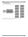
1. Features
BRC1E61
· Clear Display ························ Equipped with backlight and large sized character display and buttons.
· Stylish ··································· Basic tone is white and arrow keys are located at the center.
· Simple Operation ·················· Simple operation used with arrow keys and menu-driven method.
· Multilingual Display ··············· Available for selection of 10 languages to display arbitrarily
· Other Features······················ Wide variety of functions to meet customer needs such as schedule setting
and contact address display.
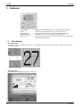
1.1
Clear Display
• Dot matrix display
A combination of fine dots enables texts and icons to be displayed smoothly and makes the display of a wide variety of text and
illustrations possible.
• Backlight display
Newly equipped backlight helps operation in dark room.
2
BRC1E61
ED72-975
1.2
Features
Stylish
Simple and Functional Design
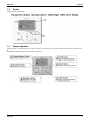
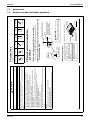
1.3
Simple Operation
Compared to the conventional structure of button allocation for each function, the number of buttons has been decreased (from 15 to
9).
Can intuitively handle frequently performed basic operations.
BRC1E61
3
Features
ED72-975
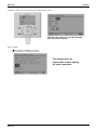
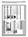
Available for simple operation with arrow keys and menu-driven system.
Available for simple operation with arrow keys and menu-driven system.
Available for simple operation with arrow keys and menu-driven system.
Select the item you wish to set with direction
keys and press "Menu/Enter" button at the
item you wish to set and the setting entry
screen appears.
4
BRC1E61
ED72-975
Features
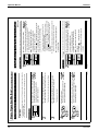
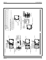
Available for simple operation with arrow keys and menu-driven system.
The item you wish to set can be changed
with up or down button.
Guide on display
The display gives an
explanation of each setting
for easier operation.
BRC1E61
5
Features
1.4
ED72-975
Multilingual Display
• Available for display in 10 different languages.
Always available for switching display by selecting from main menu.
10 languages (English, German, French, Spanish, Italian, Portuguese, Greek, Dutch, Russian and Turkish)
* Opearation Manual and Installation Manual are writen only in English.
6
BRC1E61
ED72-975
1.5
Features
Other Functions
BRC1E61
7
Functions
ED72-975
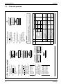
2. Functions
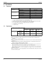
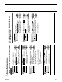
2.1
Functions
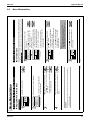
Category
Function
BRC1E61
Drawing display
Basic Functions
Convenient Functions
LCD
Operation method
Menu selection
Backlight function
{
Clock function (time display)
{
{ *1
Display switch function
{
Keylock function
{
Schedule (weekly) timer*4
{ *2
{ *2
{ *3
{*3
Model name display
Maintenance/Services
Contact dealer display
Operation time display
Operational data display
{: Possible
*1
*2-1
2-2
2-3
*3
*4
2.2
Used for setting Normal Display mode or Detailed Display mode.
When an error occurs, the error code blinks and the contact address and model names appear.
The contact address must be registered when the controller is installed.
For some models, model codes are displayed instead of model names.
Can display for some model only.
Setback function
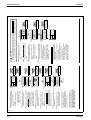
Restrictions
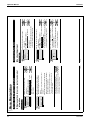
1. In the case of two remote control system.
Main
Sub
BRC1E61
BRC1D61
BRC1C61
BRC1C62
Wireless
BRC4***
BRC7***
BRC1E61
{
×
×
BRC1D61
BRC1C61
BRC1C62
{
{
×
Wireless
BRC4***
BRC7***
×
{
×
{:Connectable ×:Not connectable
Due to the limited power supply capacity, there are some restrictions when controlling 2 remote
controllers.
<Common restriction for SkyAir and VRV>
When controlling one indoor unit with 2 remote controllers, the remote controller operated first turns the
backlight on.
When controlling 2 remote controllers, schedule, limit operation, off reminder timer and home leave
functions cannot be set with the sub remote controller.
Restriction of operation from the sub remote controller
· When the On/Off button is pressed in the sub remote controller during Home Leave operation in the
main remote controller, Home Leave is stopped to return to the normal operation.
· When the Operation mode selector button, the Up button or the Down button is pressed during Limit
Operation in the main remote controller, Limit Operation is stopped to return to the normal operation.
<Restriction for VRV only>
Adaptor for wiring (KRP 1*) or power supply adaptor for indoor unit PCB (X18A or X35A) cannot be used
for 2 remote controller system.
8
BRC1E61
ED72-975
Specifications
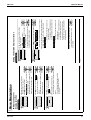
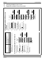
2. In the case of Centralised remote controller connection.
When connecting a centralised related device(*1), Schedule, Limit Operation and Home Leave
functions cannot be set.
(*1) this means All Centralised remote controller.
intelligent Touch Controller [DCS601C51]
intelligent Manager [DAM602B51,52]
Parallel interface [DPF201A51,52,53]
Central remote controller [DCS302CA51]
Unified ON/OFF controller [DCS301BA51]
Schedule timer [DST301BA51]
Residential central remote controller [DCS303A51]
Wiring adaptor for electrical appendices KRP2A5*/6*]
3. Quick Cooling/Heating <restriction for SkyAir only>
Under the following conditions, Quick Cooling/Heating operation stops to return to the normal operation.
· When the room temperature reaches to the set temperature, the thermostat turns OFF and the unit
returns to the normal operation.
· After 30 minutes past from the operation start, the unit returns to the normal operation.
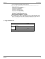
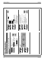
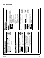
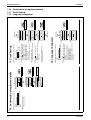
3. Specifications
New Remote Controller
BRC1E61
Dimension (mm)
H×W×D
LCD
BRC1E61
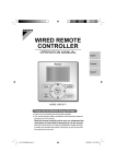
120 × 120 × 19
Display size (mm)
H×W
45.4 × 71.4
Display method
Full dot method (dot 160 × 255)
Backlight
Yes
(Background color: white)
Color
Fresh white
Cover for operation part
No
9
Dimensions
ED72-975
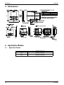
4. Dimensions
3D064037
5. Applicable Models
5.1
Applicable Models
Applicable Indoor unit
10
VRV
All models that can be connected
BRC1C62 or BRC1D61
SkyAir
All models that can be connected
BRC1C61 or BRC1D61
BRC1E61
BRC1E61
3P243520-1
Useful Information
Maintenance
Manipulating the Main Menu Screen ..................... 26
Menu Manipulation
Failure to observe these instructions properly may result in property
damage or personal injury, which may be serious depending on the
circumstances.
Failure to follow these instructions properly may result in personal
injury or loss of life.
Absolutely keep wet hands away.
Be sure to ground the unit.
2
WARNING
2/6/2009 5:49:55 PM
English
Do not clean the product with organic solvents such as paint thinner.
The use of organic solvents may cause crack damage to the product, electric shocks, or
fire.
Ɣ Do not use flammable materials (e.g., hairspray or insecticide) near the
product.
Improper installation may result in electric shocks or fire.
Consult your Daikin dealer.
Ɣ Do not relocate or reinstall the remote controller by yourself.
This may result in electric shocks or fire.
Consult your Daikin dealer.
Ɣ Do not modify or repair the remote controller.
Improper installation may result in electric shocks or fire.
Consult your Daikin dealer.
Ɣ Do not install the remote controller by yourself.
About Remote Controller
Absolutely keep water and moisture
away.
Always follow the instructions given.
Never do.
Ɣ The following pictograms are used in this manual.
CAUTION
WARNING
Ɣ The precautions described herein are classified as WARNING and CAUTION.
They both contain important information regarding safety. Be sure to observe all precautions
without fail.
Read the safety precautions attentively for the correct use of the product.
2/6/2009 5:49:55
01_EN_3P243520-1.indd
PM
2
1
After-sale Service ................................................... 54
Error code Display ................................................. 53
Maintenance of Unit and LCD ................................ 52
Filter Sign Resetting ............................................... 51
Language changeover ........................................... 50
Clock Setting .......................................................... 48
Setting Status List .................................................. 48
Convenient Functions ............................................ 45
Service Contact/Model Information ........................ 44
Timer Settings ........................................................ 34
Ventilation .............................................................. 32
Quick Cooling/Heating On/Off ................................ 31
Airflow Direction Setting ......................................... 28
Set temp mode changeover ................................... 27
Main Menu Items ................................................... 24
Ease of Cellular-like Function Settings
Key Lock ............................................................... 23
Eligibility ................................................................. 21
Setting Method of the Cooling/Heating Selection
Ventilation Operation .............................................. 20
Quick Reference of
Main Menu Items
01_EN_3P243520-1.indd 1
English
(Use of Direct Buttons)
Home Leave ........................................................... 19
Program Dry Operation .......................................... 17
Basic Operation Method
Simple Settings in Direct Buttons for
Basic Operation Items
Names and Functions ............................................... 8
Safety Precautions Items to be Strictly Observed ......... 2
Safety Precautions
6.1
Cool/Heat/Auto/Fan Operation .............................. 14
Notices
Contents
ED72-975
Operation Manual
6. Operation Manual
Safety Precautions
11
12
3P243520-1
BRC1E61
01_EN_3P243520-1.indd 3
English
Using the product in such places may cause fire or product failures.
3
4
2/6/2009 5:49:56 PM
English
The use of any other power supply may cause heat generation, fire, or product failures.
Ɣ Be sure to use a dedicated power supply for the air conditioner.
Do not operate the air conditioner in that case, or otherwise a malfunction, electric
shock, or fire may result.
Ɣ Consult the dealer if the air conditioner submerges owing to a natural
disaster, such as a flood or typhoon.
Failure to install an earth leakage breaker may result in electric shocks or fire.
Ɣ Be sure to install an earth leakage breaker.
When the air conditioner is to be installed in a small room, it is necessary to take proper
measures so that the amount of any leaked refrigerant does not exceed the
concentration limit in the event of a leakage.
Otherwise, this may lead to an accident due to oxygen depletion.
Ɣ Consult your local dealer regarding what to do in case of refrigerant
leakage.
Continued operation under such circumstances may result in a failure, electric shocks or
fire hazards.
Ɣ When the air conditioner is malfunctioning (giving off a burning odour, etc.)
turn off power to the unit and contact your local dealer.
Do not earth the unit to a utility pipe, lightning conductor or telephone earth lead. Imperfect
earthing may result in electric shocks or fire. A high surge current from lightning or other
sources may cause damage to the air conditioner.
Ɣ Be sure to earth the unit.
Otherwise, fire or water leakage may result.
Furthermore, the fan will rotate abruptly if power failure compensation is enabled, which
may result in injury.
Ɣ Do not start or stop operating the air conditioner with the power supply
breaker turned ON or OFF.
Use of an ordinary conductive wire may cause malfunctions or fire.
Ɣ In the case of using a load breaker provided with a fuse, make sure that
the capacity of the fuse is correct.
If the air conditioner is not operating correctly, i.e. not generating cool or warm air,
refrigerant leakage could be the cause. Consult your dealer for assistance. The
refrigerant within the air conditioner is safe and normally does not leak. However, in the
event of a leakage, contact with a naked burner, heater or cooker may result in generation
of noxious gas. Do not longer use the air conditioner until a qualified service person
confirms that the leakage has been repaired.
Ɣ Beware of fire in case of refrigerant leakage.
WARNING
Safety Precautions
2/6/2009 5:49:56
01_EN_3P243520-1.indd
PM
4
Ɣ Do not use the product in places with excessive oily smoke, such as
cooking rooms, or in places with flammable gas, corrosive gas, or metal
dust.
Oil vapor may cause crack damage, electric shocks, or fire.
Ɣ Do not use the product in the atmosphere contaminated with oil vapor,
such as cooking oil or machine oil vapor.
If a defect results from your own workmanship, it may result in water leaks, electric
shock or fire.
Ɣ Contact professional personnel about attachment of accessories and be
sure to use only accessories specified by the manufacturer.
Injury may result due to contact with the air conditioner’s highspeed fan blades.
Ɣ Be aware that prolonged, direct exposure to cool or warm air from the air
conditioner, or to air that is too cool or too warm can be harmful to your
physical condition and health.
Ɣ Do not place objects, including rods, your fingers, etc., in the air inlet or
outlet.
WARNING
Indoor Unit and Outdoor Unit
If water gets into the remote controller there is a risk of electrical leakage and damage to
electronic components.
Ɣ Do not leave the remote controller wherever there is a risk of wetting.
Doing so may cause electric leakage and result in electric shocks or fire.
Ɣ Do not wash the remote controller.
Ɣ To avoid electric shocks, do not operate with wet hands.
Touching the interior parts may result in electric shocks or fire.
Consult your Daikin dealer or authorized contractor for internal inspections and
adjustments.
Ɣ Never disassemble the remote controller.
Accidental operation by a child may result in impairment of bodily functions and harm
health.
Ɣ Do not play with the unit or its remote controller.
CAUTION
ʊʊItems to be Strictly Observedʊʊ
Operation Manual
ED72-975
BRC1E61
3P243520-1
01_EN_3P243520-1.indd 5
English
5
6
2/6/2009 5:49:57 PM
English
If proper drainage from the outdoor drain pipe does not occur during air conditioner
operation, there could be a blockage due to dirt and debris build-up in the pipe.
This may result in a water leakage from the indoor unit. Under these circumstances,
stop air conditioner operation and consult your dealer for assistance.
Ɣ Arrange the drain to ensure complete drainage.
If the units are not mounted securely, the units may fall or topple and injury may result.
Ɣ Fix the units securely.
Leaves are a hotbed for small animals which can enter the unit. Once in the unit, such
animals can cause malfunctions, smoke or fire when making contact with electrical
parts.
Ɣ Do not place objects in direct proximity of the outdoor unit and do not let
leaves and other debris accumulate around the unit.
The use of an incorrect washing method or incorrect detergent may damage the resin
parts of the indoor unit or cause water leakage.
Moreover, malfunctions, smoke generation, or ignition may result if the electric parts or
motor in the indoor unit is wet with detergent.
Ɣ Do not wash the interior of the indoor and outdoor units by yourself.
Always consult your Daikin dealer.
Failure to do so may result in an electric shock or injury.
Ɣ Always stop the operation of the air conditioner and turn OFF the
breaker at the time of cleaning.
Be careful when using the air conditioner with other heating equipment.
Insufficient ventilation may result in oxygen deficiency.
Ɣ Perform ventilation from time to time.
Ɣ Do not wash the air conditioner with water, as this may result in electric
shocks or fire.
The motor in operation is at high temperatures and a burn may result.
Ɣ Do not touch the motor at the time of filter replacement.
The base may topple down and injury may result.
Ɣ Do not sit or stand on any unstable base at the time of operating or
maintaining the air conditioner.
CAUTION
Safety Precautions
2/6/2009 5:49:56
01_EN_3P243520-1.indd
PM
6
In the event of a gas leakage, build-up of gas near the air conditioner may result in fire
hazards.
Ɣ Do not install the air conditioner at any place where there is a danger of
flammable gas leakage.
The containers may explode because the warm air output of the indoor or outdoor unit
will affect them.
Ɣ Do not put flammable containers, such as spray cans, within 1m from the
blow-off mouth.
Ɣ Be sure that children, plants or animals are not exposed directly to
airflow from the unit, as adverse effects may ensue.
Ɣ Do not place heaters directly below the unit, as resulting heat can cause
deformation.
Ɣ Do not place appliances that produce naked flames in places exposed to
the air flow from the unit as this may impair combustion of the burner.
Do not use the air conditioner for cooling precision instruments, food, plants, animals or
works of art as this may adversely affect the performance, quality and/or longevity of the
object concerned.
Ɣ Do not use the air conditioner for purposes other than those for which it
is intended.
Ɣ Do not place water containers (flower vases, etc.) on the unit, as this
may result in electric shocks or fire.
Under certain conditions, condensation on the main unit or refrigerant pipes, air filter dirt
or drain blockage may cause dripping, resulting in fouling or failure of the object
concerned.
Ɣ Do not place objects that are susceptible to moisture directly beneath
the indoor or outdoor units.
The guard protects against the unit’s high speed fan, which may cause injury.
Ɣ Do not remove the outdoor unit’s fan guard.
Ɣ To avoid injury, do not touch the air inlet or aluminium fins of the unit.
Impaired air flow may result in insufficient performance or trouble.
Ɣ Do not block air inlets nor outlets.
Falling or tumbling may result in injury.
Ɣ Do not allow a child to mount on the outdoor unit or avoid placing any
object on it.
If left in a damaged condition, the unit may fall and cause injury.
Ɣ After prolonged use, check the unit stand and its mounts for damage.
CAUTION
ʊʊItems to be Strictly Observedʊʊ
ED72-975
Operation Manual
13
14
3P243520-1
BRC1E61
English
Ɣ Used to highlight the next items on the
right-hand side.
Ɣ Each screen is scrolled in the right-hand
direction.
Ɣ Home leave settings are enabled with this
button kept pressed for at least four
seconds. (See page 19.)
6. Right button (Be sure to press
the part with the symbol )
Ɣ Used to lower the set temperature.
Ɣ The next items on the lower side will be
highlighted.
(The highlighted items will be scrolled
continuously when the button is kept
pressed.)
Ɣ Used to change the item selected.
5. Down button (Be sure to press
the part with the symbol )
Ɣ Used to raise the set temperature.
Ɣ The next items on the upper side will be
highlighted.
(The highlighted items will be scrolled
continuously when the button is kept
pressed.)
Ɣ Used to change the item selected.
4. Up button (Be sure to press the
part with the symbol )
Ɣ Used to indicate the main menu.
(See page 24 for the menu items.)
Ɣ Used to enter the setting item selected.
3. Menu/Enter button
Ɣ Press this button to select the fan speed of
your preference. (See page 15.)
* Available fan speed vary with the
connecting model.
2. Fan speed control button
2/6/2009 5:49:57
01_EN_3P243520-1.indd
PM
9
English
Ɣ Do not install the remote controller in places exposed to direct sunlight.
Otherwise, the LCD may become discolored and nothing may be displayed.
Ɣ Do not pull or twist the remote controller cord.
Otherwise, the remote controller may error.
Ɣ Do not press the buttons on the remote controller with objects with sharp ends.
Otherwise, the remote controller may receive damage or error.
NOTE
01_EN_3P243520-1.indd 8
8
2. Fan speed control
button
10. Cancel button
3. Menu/Enter button
8. On/Off button
9. Operation lamp
4. Up button
5. Down button
6. Right button
7. Left button
11. LCD (with backlight)
1. Operation mode
selector button
Ɣ Press this button to select the operation
mode of your preference. (See page 14.)
* Available modes vary with the connecting
model.
1. Operation mode selector button
2/6/2009 5:49:57 PM
9
Ɣ The backlight will be light for approximately
30 seconds by pressing any operation
button. Operate buttons excluding the On/
Off button while the backlight is lit.
Ɣ If two remote controllers are used to control
a single indoor unit, the backlight of the
remote controller operated earlier than the
other one will be lit.
11. LCD (with backlight)
Ɣ Used to return to the previous screen.
10.Cancel button
Ɣ This lamp lights up during operation.
Ɣ This lamp blinks if a error occurs.
9. Operation lamp (Green)
Ɣ Press this button and system will start.
Ɣ Press this button again and system will
stop.
8. On/Off button
Ɣ Used to highlight the next items on the
left-hand side.
Ɣ Each screen is scrolled in the left-hand
direction.
Ɣ Home leave settings are enabled with this
button kept pressed for at least four
seconds. (See page 19.)
7. Left button (Be sure to press
the part with the symbol )
6.2
Functions other than basic operation items (i.e., On/Off, Operation
mode selector, Fan speed control, and temperature settings) are set
from the menu screen.
Names and Functions
Operation Manual
ED72-975
Names and Functions
BRC1E61
<Standard display example>
This function not available
20°C
Set temperature
) display
6.Message
4.Set temperature
display
5.Defrost/Hot start
8.(
12.Home Leave
9.( ) display
3P243520-1
01_EN_3P243520-1.indd 10
10
(with no airflow direction
settings)
Airflow direction
display
(with no fan speed
control function)
3.Fan speed display
(Displayed only when
the air conditioner is in
operation.)
13.Airflow direction
12:05
Setting
20°C
20°C
Set temp Room
--:--
Setting
20°C
Set temp
<Detailed display example 2>
Return
Heat
Auto
A
<Detailed display example 1>
Return
Heat
Auto
A
) display
”
English
Ɣ Displayed for a few seconds when an
operation button is pressed if the indoor
unit is not provided with the corresponding
function.
Ɣ If a number of indoor units are in operation,
the message will appear only if none of the
indoor units is provided with the
corresponding function, i.e., the message
will not appear if at least one of the indoor
units is provided with the corresponding
function.
The following messages are displayed.
“This function not available.”
6. Message
If Ventilating operation “
” is displayed:
Ɣ Displayed when a total heat exchanger
unit, such as the Ventiair, is connected.
For details, refer to the Operation Manual
of the Ventiair.
(See page 16.)
5. Defrost/Hot start “
Ɣ Used to display the temperature set for the
air conditioner.
4. Set temperature display
Ɣ Used to display the fan speed that is set for
the air conditioner.
Ɣ The fan speed will not be displayed if the
air conditioner does not have fan speed
control function.
3. Fan speed
Ɣ Used to display the present automatic
operation mode (Cool or Heat).
2. Automatic operation mode
Ɣ Used to display the present operation
mode Cool, Heat, Vent, Fan, Dry or Auto
mode.
1. Operation mode
2/6/2009 5:49:57
01_EN_3P243520-1.indd
PM
11
English
(with no detailed items
selected)
Detailed selection
16. (
(with no clock settings)
Clock display
(with room
temperature settings)
15.Detailed selection
14.Clock (24 hours
real time clock)
The airflow direction, clock, and detailed selection items appear
on the detailed display screen in addition to the items appearing
on the standard display.
Detailed display
7.Ventilation
3.Fan speed
2.Automatic
operation mode
Heat
11. Changeover under control
10.Under centralized
control
1.Operation mode
Auto
Standard display
Ɣ Two types of liquid crystal display (LCD) are available. The standard display is by
default set.
Ɣ To go to the detailed display, select the detailed display in the main menu. (See page 46.)
Ɣ The displayed contents of the screen vary with the operation mode of the equipment
interlocked. (The following display will appear when the air conditioner is in automatic
heating operation.)
Liquid Crystal Display
Names and Functions
display (See page 23.)
Ɣ Displayed if the schedule timer or OFF
reminder timer is enabled.
display (See page 34.)
Ɣ Displayed when the key lock is set.
11
”
2/6/2009 5:49:58 PM
Ɣ Displayed on the remote controller if the
remote controller has no cooling/heating
selection eligibility mode (see page 21).
(VRV only)
11. Changeover under control “
Ɣ Displayed if the system is under the
management of central control equipment
(optional accessories) and the operation of
the system through the remote controller is
prohibited.
10.Under Centralized control “ ”
9.
8.
Ɣ Displayed when a total heat exchanger
unit, such as the Ventiair, is connected.
Ɣ Ventilation mode icon.“
”
These icons indicate the current ventilation
mode (HRV only) (AUTOMATIC, HEAT
EXCHANGE, BYPASS).
”
Ɣ AIR Purifying ICON “
This icon indicates that the air cleaning unit
(option) is operational.
7. Ventilation / Purifying
“Clean the filter.”
“Clean the element.”
“Clean the filter and element.”
Ɣ Displayed when the time to clean the filter
or element has come (see page 51).
“Quick Cool/Heat” (SkyAir only)
Ɣ Displayed if the quick cooling/heating
function is turned ON (see page 31).
“Error: Press Menu Button.”
“Warning: Press Menu Button.”
Ɣ Displayed if the error or warning is detected
(see page 53).
ED72-975
Operation Manual
15
16
” (See page 19.)
3P243520-1
BRC1E61
01_EN_3P243520-1.indd 12
12
display
Ɣ Displayed to inform that the clock needs
setting again.
Ɣ The schedule timer function will not work
unless the clock is set again.
16.
Ɣ Displayed if the detailed display items are
selected (see page 47).
Ɣ No detailed items are by default selected.
15.Detailed selection
Ɣ Displayed if the clock is set (see page 48).
Ɣ If the clock is not set, “ -- : -- ” will be
displayed.
14.Clock (24 hours real time clock)
Ɣ Displayed when the airflow direction and
swing are set (see page 28).
Ɣ This item is not displayed if the system is
not provided with a function to set airflow
directions.
”
Home Leave is disabled
OFF
13.Airflow direction “
Home Leave is active
FLASHING
Ɣ The home leave icon shows the status of
the home leave function.
ON
Home leave is enabled
12.Home leave “
Names and Functions
English
2/6/2009 5:49:58
01_EN_3P243520-1.indd
PM
13
English
2/6/2009 5:49:58 PM
13
Operation Manual
ED72-975
BRC1E61
1
3P243520-1
01_EN_3P243520-1.indd 14
Return
Cool
Return
Setting
28°C
Set temperature
Operation Method
14
Setting
Setting
Schedule timer
Off reminder timer
Timer setting
Return
Set temp mode changeover
Airflow Direction
Quick Cool/Heat On/Off
Ventilation
Timer setting
Service Contact/Model info
MainMenu
Disable
Disable
2/2
1/2
buttons to select
* Items presently enabled or disabled are
displayed.
screen.
Press Menu/Enter button to display
the timer settings screen.
Timer setting on the main menu
Ɣ Press
(See page 26.)
Ɣ Displays the main menu screen.
Explains a button operation
procedure for the remote controller.
Operate the buttons according to
the procedure.
Displays the positions of
buttons to be operated.
Operation button
display
English
5
4
3
2
Low
Return
Cool
Return
Cool
Middle
Setting
28°C
Set temperature
Setting
28°C
Set temperature
High
2/6/2009 5:49:58
01_EN_3P243520-1.indd
PM
15
English
Note
Ɣ Before making a mode change, make sure that Changeover
under control is not displayed on the remote controller.
The cooling or heating mode cannot be selected if the above is
displayed on the remote controller. See page 21 if Changeover
under control display blinks.
* Unavailable operation modes are not displayed.
* Only the Cooling or Fan mode can be selected if the air
conditioner is a cooling-only model.
* The Auto mode can be set in the case of the VRV cooling/
heating simultaneous operation system.
* Changeover under control will appear on each remote controller,
but only the Cooling or Fan mode can be set in the case of the
VRV cooling-only system.
Ɣ Press Operation Mode Selector button
several times until the desired mode
Cooling, Heating, Fan, or Auto mode is
selected.
Ɣ For mechanical protection purposes, turn ON the system at least six hours before starting the
operation of the system.
Ɣ Do not turn OFF the system in season in order to ensure the smooth starting of the system.
Preparation
Describes screens that
will be displayed on the
remote controller in
operation.
Operation screen
display
1
Operation Method
Remote Controller Functions
Operation procedure
(SkyAir and VRV)
15
2/6/2009 5:49:59 PM
* The airflow direction of the system cannot be changed unless
the system is provided with a function to allow airflow direction
changes.
Ɣ Make airflow direction settings from the main menu
(see page 28).
* Two fan speed adjustment levels Low, High may be available
depending on the type of indoor unit.
* The system may be in automatic fan speed control for
mechanical protection purposes.
* The system may be in automatic fan speed control according to
the room temperature.
The fan may stop operating, which, however, is not a failure.
* The completion of fan speed selection may take time, which,
however, is not a failure.
Ɣ To make fan speed control, press Fan
speed control button and select the
desired fan speed from Low, Middle or
High.
* No temperature settings are possible while in fan mode.
Ɣ The set temperature will increase by
1°C when button is pressed and
decrease by 1°C when button is
pressed.
Ɣ Press On/Off button.
The Operation lamp (green) will be lit
and the system will start operating.
6.3
Cool/Heat/Auto/Fan Operation
Basic Operation Method (Use of Direct Buttons)
ED72-975
Operation Manual
Basic Operation Method (Use of Direct Buttons)
17
18
Note
Ɣ Do not turn power OFF soon after the system stops operating.
Be sure to wait for at least five minutes so that the drain
discharging device will finish discharging the residual drain.
Otherwise, water leakage or failures may result.
* While the system is in heating operation, the
system will be in fan operation for approximately
one minute in order to eliminate the heat in the
indoor unit after the heating operation comes to a
stop.
Ɣ The system in heating operation generally requires a long time to
attain the set temperature compared with the system in cooling
operation.
It is recommended to start operating the system in advance by utilizing
the timer.
3P243520-1
BRC1E61
01_EN_3P243520-1.indd 16
Ɣ The heating capability of the system will drop with a decrease in
outdoor temperature.
If that happens, use the system along with another heating appliance.
(In the above case, be sure to ventilate the room as frequently as
possible.)
Do not use the heating appliance in places where the heating
appliance is exposed to the wind from the system.
Ɣ The system is of hot air circulation type. Therefore, it takes some time
for the room to become warm after the system starts operating.
The indoor fan will automatically go into breezing operation until the
inner temperature of the system rises to a certain level.
Ɣ If the hot air stays around the ceiling and your feet feel cold, the use of
a circulator is recommended.
For details, consult your Daikin dealer.
English
1
Return
Dry
Setting
28°C
Set temperature
Operation Method
2/6/2009 5:50:00 PM
17
* The dry operation may not be available depending on the type of
indoor unit.
Ɣ Press Operation Mode Selector button
several times until the Dry operation is
selected.
Ɣ For mechanical protection purposes, turn ON the system at least six hours before starting the
operation of the system.
Ɣ Do not turn OFF the system in season in order to ensure the smooth starting of the system.
Ɣ The dry mode may not be selected if the remote controller has no right to select cooling/
heating mode (see page 22 for details).
Preparation
Program Dry Operation
Outdoor
temperature and
heating capability
2/6/2009 5:49:59
01_EN_3P243520-1.indd
PM
17
English
Ɣ When the system goes into heating operation, the wind will stop in
order to prevent cold air from blowing out of the system in defrosting
operation.
” (Defrost/Hot start) will be displayed on the
(In that case, “
remote controller.)
Hot start
(VRV only)
16
Ɣ The heating capability of the system will drop if the outdoor unit frosts
up. Therefore, the system will go into defrosting operation
automatically.
” (Defrost/Hot
Ɣ The system will stop blowing out hot air, and “
start) will be displayed on the remote controller.
Ɣ The system will return to normal operation with an elapse of
approximately six to eight minutes (but not more than 10 minutes).
Defrosting
operation
Perform the following operation of the system in order to prevent the
degradation of the heating capability or cold winds from blowing out.
Starting operation
Characteristics of Heating Operation
6
Ɣ The Operation lamp will be turned OFF
and the system will stop operating when
On/Off button is pressed again.
Basic Operation Method (Use of Direct Buttons)
Operation Manual
ED72-975
BRC1E61
3P243520-1
01_EN_3P243520-1.indd 18
18
4
3
2
19
%
(
&'"#
% #
%
(
&'"#
% ) * ) * +, -
./
0 1%2/3
.00
) * ) * +,
$ #
!"# 2/6/2009 5:50:00 PM
English
Note
Ɣ Do not turn power OFF soon after the system stops operating.
Be sure to wait for at least five minutes so that the drain
discharging device will finish discharging the residual drain.
Otherwise, water leakage or failures may result.
Ɣ The Operation lamp will be turned OFF
and the system will stop operating when
On/Off button is pressed again.
* The airflow direction of the system cannot be changed unless the
system is provided with a function to allow airflow direction
changes.
Ɣ Make airflow direction settings from the main menu
(see page 28).
* The microcomputer is in automatic temperature and fan speed
control. Therefore, temperature or fan speed settings cannot be
made or changed while the air conditioner is in operation.
Ɣ Press On/Off button.
The Operation lamp (green) will be lit
and the system will start operating.
Basic Operation Method (Use of Direct Buttons)
ED72-975
Operation Manual
20
5
4
3
2
1
3P243520-1
BRC1E61
01_EN_3P243520-1.indd 20
Return
Vent
Setting
20°C
Set temperature
Operation Method
20
When Air Conditioner Interlocked with Total Heat Exchanger
Ɣ The Operation lamp will be turned OFF
and the system will stop operating when
On/Off button is pressed again.
Ɣ Press On/Off button.
The Operation lamp (green) will be lit
and the system will start operating.
* Ventilation rate: Low or High
English
Return
Cool
Return
Cool
English
2
Return
Cool
Return
Cool
28°C
Setting
28°C
Set temperature
Setting
28°C
Set temperature
The display “
Setting
28°C
Set temperature
Setting
Ɣ Press Operation Mode Selector button
of the remote controller for which the
selection eligibility to be set.
Then the cooling/heating selection
eligibility will be set and the display
” (Changeover under control) will
“
disappear.
” (Changeover under
The display “
control) will appear on the other remote
controllers.
2/6/2009 5:50:01 PM
21
” (Changeover under control) will blink when the power is turned ON for the first time.
Ɣ Set a cooling/heating selection eligibility as
explained below.
* Vent mode setting changes are possible regardless of the
cooling/heating selection eligibility.
* If a cooling/heating selection eligibility is set in the cooling/
heating selection remote controller ( ), all the remote controllers
” (Changeover under control). In this case, no
will display “
cooling/heating selection eligibility can be set in the remote
controllers.
Refer to the operation manual provided to the outdoor unit for the
details of the cooling/heating selection remote controller.
Ɣ Continue pressing Operation Mode
Selector button of the remote controller for
at least four seconds. (During backlight lit)
A remote controller will not display
” (Changeover under control) if a
“
cooling/heating selection eligibility is
granted to the remote controller.
Ɣ The display “
” (Changeover under control) on
each remote controller connected to the same
outdoor unit or BS unit will start blinking.
See page 22 for an explanation of the cooling/heating selection eligibility.
Set temperature
Selection Settings
1
Setting Changes
(VRV only)
Setting Method of the Cooling/Heating Selection Eligibility
2/6/2009 5:50:00
01_EN_3P243520-1.indd
PM
21
Ɣ To change the ventilation rate, make necessary
settings from the main menu (see page 32).
* Ventilation mode: Automatic, Heat exchange, and Bypass
Ɣ To change the ventilation mode setting, make
necessary settings from the main menu (see page 33).
Ɣ Set the Operation mode selector button
to Ventilation in the case of operating
the total heat exchanger without the
system between seasons.
Ɣ For mechanical protection purposes, turn ON the system at least six hours before starting the
operation of the system.
Ɣ Do not turn OFF the system in season in order to ensure the smooth starting of the system.
Preparation
Ventilation Operation
Basic Operation Method (Use of Direct Buttons)
Operation Manual
ED72-975
BRC1E61
Return
Cool
Setting
28°C
Set temperature
Ɣ Press the remote controller that has the
cooling/heating selection eligibility (or
the remote controller without the display
” (Changeover under control))
“
several times until the desired mode is
selected. The display will change to
“Fan”, “Dry”, “Auto”, “Cool”, “Heat” each
time the button is pressed.
Ɣ The display “Auto” will appear for the
heating/cooling simultaneous operation
system only.
At that time, the other remote controllers
with no selection right will follow suit and
change the display automatically.
The remote controller with
the selection eligibility
”
(without “
(Changeover under
control) displayed)
1.
2.
3P243520-1
01_EN_3P243520-1.indd 22
22
The remote controller with
the selection eligibility
”
(without “
(Changeover under
control) displayed)
Set to “Fan” mode.
Set to “Cool”, “Heat”,
“Dry”, “Auto” mode.
English
2
1
Setting
28°C
Set temperature
Return
Cool
Setting
28°C
Set temperature
Basic screen
Return
Cool
Operation Method
Ɣ “ ” will appear.
All buttons are disabled when the keys
are locked.
Ɣ To cancel the key lock mode, continue
pressing Menu/Enter button for at least
four seconds. (During backlight lit)
Ɣ Continue pressing Menu/Enter button for
at least four seconds. (During backlight lit)
Make settings and cancel settings in the basic screen.
23
2/6/2009 5:50:01 PM
Set the cooling/heating/auto/fan selection
eligibility in one of the remote controllers.
Set the cooling/heating/fan selection
eligibility in one of the remote controllers.
Key Lock
A single BS unit is connected to a
number of indoor units.
Indoor unit
BS unit:
The BS unit is used for cooling or
heating mode selection.
(Cooling/Heating simultaneous operation system)
A number of indoor units are
connected to a single outdoor unit.
Indoor unit
(Cooling/Heating selected operation system)
Ɣ The cooling/heating selection eligibility needs to be set for a single remote controller in the
following case.
Precautions for Setting Cooling/Heating Selection Eligibility
2/6/2009 5:50:01
01_EN_3P243520-1.indd
PM
23
English
Ɣ The system cannot be set to other
modes except fan mode.
(with “
”
(Changeover under
control) displayed)
Other remote controllers
Ɣ The system will go into the mode set in
the remote controller. No other modes
are available.
Ɣ The system, however, can be switched
to fan mode or from “Cool” to “Dry”.
(with “
”
(Changeover under
control) displayed)
Other remote controllers
Ɣ The “Cool”, “Heat”, “Auto” can be set for only the remote controller for which the cooling/heating
selection eligibility is set.
(The display “Auto” will appear for the heating/cooling simultaneous operation system only.)
Cool/Heat Selection Eligibility
3
Operation Selection
Basic Operation Method (Use of Direct Buttons)
ED72-975
Operation Manual
21
22
Ventilation mode
Ventilation rate
3P243520-1
BRC1E61
01_EN_3P243520-1.indd 24
24
Service Contact/Model
Information
Off reminder timer
Timer setting Schedule timer
Ventilation
operation
settings for total
heat exchanger
Ventilation
(SkyAir only)
Used to display the service contact and model
information.
Ɣ Possible to set in 10 minute units from 30 to
180 minutes.
Used to set each operation period of the system.
* Clock settings are necessary.
* The system goes into schedule timer operation in
the previous mode set for the system.
Standard or detailed
display
Menu Items of Sub Remote Controller
English
Ɣ Set temp mode changeover
Ɣ Schedule timer
Ɣ Off reminder timer
Ɣ Home leave
If two remote controllers are in control of a single indoor
unit, the following menu items are not set in the sub remote
controller. Set them in the main remote controller.
Outdoor unit
2/6/2009 5:50:03 PM
25
Two remote
controllers in control
50
48
48
46
45
Reference page
Indoor unit
The displayed language can be selected from
the following language. (English/Deutsch/
Français/Español/Italiano/EȜȜȘȞȚțȐ/
Nederlands/Portugues/PyccƸɢɣ/Ɍürkçe)
Ɣ The clock is in 24 hours real time clock.
Ɣ The accuracy of the clock is within
±30 seconds per month.
Ɣ If there is a power failure for a period not
exceeding 48 hours, the clock will continue
working with the built-in backup power
supply. The clock needs settings again if the
power failure period exceeds 48 hours.
Note: Available setting items vary with the model connected.
Only the available setting items appear in the menu.
Language changeover
Clock setting
Used to make date and time settings and
corrections.
Ɣ Used to display a list of current settings for
available items.
Ɣ Display
Standard or detailed display
Ɣ Detailed display settings
Selectable from the display room
temperature, outdoor temperature, system, or
without any display items.
Used to set to standard or detailed display
mode.
Display changeover
Setting status list
2/6/2009 5:50:03
01_EN_3P243520-1.indd
PM
25
English
44
42
35
33
Used to set Automatic, Heat exchange, and
Bypass.
Ɣ Operation start time and stop time can be
set according to the day of the week.
Either one of the following operation modes
can be selected.
• Operation at set temperature: Normal
operation
• Operation within set temperature range
(between max. and min. temperatures):
Limit operation
Up to 5 actions can be set for each day.
Ɣ Convenient holiday settings and temporary
closure settings are possible.
32
31
Used to set to “Low” “High”
Used to set the room to a conformable
temperature quickly (unless the system is
not in program dry or fan operation).
Ɣ The maximum quick cooling/heating
operation period is 30 minutes.
* This function is not available to all models.
Used to make airflow direction settings.
Ɣ The airflow direction blade are automatically
operated up and down (left and right).
Ɣ The fixed airflow directions are set to five
positions.
Quick Cooling/Heating On/Off
27
Select normal set temperature or limit control.
Set temp mode changeover
Airflow direction setting
28
Reference page
Description
Setting and display items
Description
Used to make LCD contrast adjustment.
Contrast adjustment
Setting and display items
Convenient
functions
6.4
The main menu has the following items.
Quick Reference of Main Menu Items
Operation Manual
ED72-975
Quick Reference of Main Menu Items
BRC1E61
3P243520-1
Setting
1/2
Main menu screen
Return
Set temp mode changeover
Airflow Direction
Quick Cool/Heat On/Off
Ventilation
Timer setting
Service Contact/Model Info
MainMenu
Ɣ To go back to the basic screen from the
main menu screen, press the Cancel
button.
2. Press Menu/Enter button to display the
selected settings screen.
1. Press
buttons to select the desired
item to be set.
Ɣ Selecting items from the main menu.
Instructions for manipulating the
buttons will appear.
Ɣ The main menu screen will appear.
English
3
2
1
28 °C
20 °C
min
28 °C
20 °C
min
28 °C
20 °C
Set temperature
max
Return
Press the menu button
Fan
Return
Press the menu button
min
Set temperature
max
Basic screen
Fan
1/2
Ɣ Pressing
buttons switches the
variable set temperature between
max. and min.
Note
Ɣ The difference between the maximum and minimum
temperatures cannot be set to less than 6°C.
(* Maximum temperature – Minimum temperature 6°C)
Ɣ To change the set temperature,
buttons.
press
The set temperature is highlighted
and ready to be changed.
Ɣ The set temperature will increase by
1°C when the button is pressed
and decrease by 1°C when the
button is pressed.
* To return to the normal set temperature
screen, use “Set temp mode changeover” in
the Main Menu again.
Ɣ Press
buttons to select “Set
temp mode changeover” on the
main menu screen.
Ɣ Pressing Menu/Enter button takes
you back to the basic screen, and
the set temperature is displayed in
max °C min °C. (Limit Operation)
(See page 26.)
Ɣ Display the main menu screen.
2/6/2009 5:50:03 PM
27
The limit operation can not be enabled when a centralized control is connected.
Set temperature
max
Setting
Return
Press the menu button
Fan
Return
Set temp mode changeover
Airflow Direction
Quick Cool/Heat On/Off
Ventilation
Timer setting
Service Contact/Model Info
MainMenu
2/6/2009 5:50:03
01_EN_3P243520-1.indd
PM
27
English
Ɣ While setting items, if a button is not pressed for 5 minutes, the screen will automatically go
back to the basic screen.
01_EN_3P243520-1.indd 26
26
Setting
28°C
Set temperature
Basic screen
Return
Cool
Caution
4
3
2
1
Operation Method
Operation Method
Ɣ Press Menu/Enter button.
Limit Operation
Limit operation provides thermostat control within the range of the set minimum and maximum temperature.
The minimum temperature setting will trigger heating. The maximum temperature setting will trigger cooling.
Display Method for Main Menu
Set temp mode changeover
6.5
Manipulating the Main Menu Screen
Menu Manipulation
ED72-975
Operation Manual
Menu Manipulation
23
24
3P243520-1
BRC1E61
Setting
Setting
1/2
Setting
Airflow direction
setting (left/right)
Return
Swing
Airflow Direction
Airflow direction
setting (up/down)
Return
Swing
Airflow Direction
Return
Set temp mode changeover
Airflow Direction
Quick Cool/Heat On/Off
Ventilation
Timer setting
Service Contact/Model Info
01_EN_3P243520-1.indd 28
28
2
1
MainMenu
Operation Method
2
3 4
Up/down direction
0
1
1
2
3
4
Left/right direction
0
0
1
2
3
4
English
0
1
2
3
4
English
4
3
Setting
Setting
Setting
Setting
Left/right direction
Return
Position 2
Airflow Direction
Up/down direction
Return
Position 2
Airflow Direction
Left/right direction
Return
Swing
Airflow Direction
Up/down direction
Return
Swing
Airflow Direction
2/6/2009 5:50:04
01_EN_3P243520-1.indd
PM
29
: Position
: Position
: Position
: Position
: Position
Note
Ɣ Airflow direction appears on the screen as below.
Ɣ The airflow direction setting screen will
appear.
(For models with no airflow direction
adjustment, Airflow Direction will not be
displayed on the main menu screen.)
Ɣ Press
buttons to select
Airflow Direction on the main menu
screen and press the Menu/Enter
button.
(See page 26.)
Ɣ Display the main menu screen.
Manipulating Airflow Direction Setting
Airflow Direction Setting
Menu Manipulation
Ɣ Press
buttons to select the
desired airflow direction.
Press Menu/Enter button to return
to the basic screen.
* The illustration is a display when position 2
is selected.
Ɣ When you select one of positions 0
to 4, the airflow direction blades
stay in a fixed position.
Ɣ Selecting Swing will cause the
airflow direction blades to swing
back and forth.
For the swing setting only, all
positions will be displayed.
Ɣ Pressing
buttons changes the
setting to (in order) Swing ,
Position 0 ,
Position 1 ,
Position 2 ,
Position 3 , and
Position 4 .
2/6/2009 5:50:04 PM
29
Operation Manual
ED72-975
BRC1E61
(Automatic)
3P243520-1
(Desired position)
(Desired position)
Heating mode includes automatic operation.
Operation
condition
1/2
28°C
Set temperature
Setting
Quick Cool/Heat
Cool
Return
Set temp mode changeover
Airflow Direction
Quick Cool/Heat On/Off
Ventilation
Timer setting
Service Contact/Model Info
MainMenu
Ɣ While operating in Cooling, Heating, or
Auto mode, display the main menu
screen (see page 26).
buttons to select
Ɣ Press
Quick Cool/Heat On/Off on the main
menu screen.
Press Menu/Enter button to return to the
basic screen.
Ɣ Quick Cooling/Heating will appear on
the basic screen.
Quick Cooling/Heating is now on.
English
2
Return
Cool
Return
1/2
Setting
28°C
Set temperature
Setting
Set temp mode changeover
Airflow Direction
Quick Cool/Heat On/Off
Ventilation
Timer setting
Service Contact/Model Info
MainMenu
Operation Method
Ɣ While Quick Cooling/Heating is
displayed on the basic screen, display
the main menu screen (see page 26).
buttons to select
Ɣ Press
Quick Cool/Heat On/Off on the main
menu screen.
Press Menu/Enter button to return to the
basic screen.
Ɣ Quick Cooling/Heating will no longer
appear on the basic screen.
Ɣ Quick Cooling/Heating is now off.
Quick Cooling/Heating Off
1
Operation Method
Quick Cooling/Heating On
Quick Cooling/Heating On/Off
2/6/2009 5:50:04
01_EN_3P243520-1.indd
PM
31
English
Ɣ Room temperature is higher than the remote controller’s set temperature
(in heating mode).
Ɣ When defrosting (in heating mode).
(The airflow is blowing horizontally so that people in the room are not in
direct line of the cold air.)
Ɣ Under continuous operation with the airflow blowing horizontally.
Under the operation conditions shown below, airflow direction is controlled automatically. Actual
operation may thus be different than what is displayed on the remote controller.
01_EN_3P243520-1.indd 30
30
Airflow direction
You can select from one of five fixed
directions. (This has no relation to the
angle of the louvers.)
Indoor unit
Movement of airflow direction blades
(Automatic)
Indoor unit
The airflow direction blades automatically
swing up and down.
Airflow direction swing
There are two types of airflow direction setting.
Operational Details and Functions
Menu Manipulation
2/6/2009 5:50:05 PM
31
ED72-975
Operation Manual
25
26
The indoor unit is automatically controlled, increasing the power of the
outdoor unit and quickly bringing the room to a comfortable temperature.
Return
Ventilation rate
Ventilation mode
Ventilation
Return
Setting
Setting
Set temp mode changeover
Airflow Direction
Quick Cool/Heat On/Off
Ventilation
Timer setting
Service Contact/Model Info
MainMenu
2/2
1/2
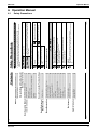
Press Menu/Enter button to display the
ventilation settings screen.
(For models with no ventilation function,
Ventilation will not be displayed on the main
menu screen.)
Ɣ Press
buttons to select Ventilation
on the main menu screen.
(See page 26.)
Ɣ Display the main menu screen.
3P243520-1
BRC1E61
Return
Ventilation rate
Ventilation mode
01_EN_3P243520-1.indd 32
32
1
Ventilation
Setting
Operation Method
2/2
Ɣ Bring up the ventilation settings screen
(see above).
buttons to select
Ɣ Press
Ventilation rate on the ventilation
settings screen.
Press Menu/Enter button to display the
ventilation rate settings screen.
Changing the ventilation rate
1
Operation Method
Display method for ventilation settings screen
Ventilation
Low
Return
Setting
High
Ventilation rate
Ventilation
High
(Pressing Cancel button takes you back to the
previous screen without changing the ventilation
rate.)
Ɣ Selecting the desired ventilation rate
and pressing Menu/Enter button selects
the setting and takes you back to the
basic screen.
* Only modes that can be set are displayed.
Ɣ Pressing
buttons changes the
setting to in order Low and High .
English
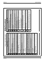
2
1
Return
Setting
Setting
Bypass
Ventilation mode
Ventilation
Return
Ventilation rate
Ventilation mode
Ventilation
Operation Method
2/2
2/2
Heat exchange
Automatic
* Only modes that can be set are displayed.
Bypass
Ɣ Pressing
buttons changes the
settings in order as shown below.
Ɣ Press
buttons to select
Ventilation mode on the ventilation
settings screen.
Press Menu/Enter button to display the
ventilation mode settings screen.
(See page 32.)
Ɣ Display the ventilation settings screen.
Changing ventilation mode
3
2
2/6/2009 5:50:05
01_EN_3P243520-1.indd
PM
33
English
Ɣ Fan speed display goes off and fan speed can no longer be switched.
Ɣ Cannot be set when in fan and dry modes.
Ɣ Quick Cooling/Heating mode will run for a maximum of 30 minutes before the unit automatically
returns to normal operation.
Ɣ Activating mode selector will return the air conditioner to normal operation.
Ɣ In heating mode, fan speed may increase and the wind temperature may decrease.
Adjust the operation as desired.
Quick Cooling/Heating
Quick Cooling/Heating
Menu Manipulation
2/6/2009 5:50:05 PM
33
Operation Manual
ED72-975
BRC1E61
Return
Cool
Setting
28°C
Set temperature
3P243520-1
Setting
Return
Cool
Return
Disable
Disable
2/2
1/2
Setting
28°C
Set temperature
Setting
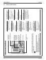
Schedule timer
Off reminder timer
Timer setting
Return
01_EN_3P243520-1.indd 34
34
1
Set temp mode changeover
Airflow Direction
Quick Cool/Heat On/Off
Ventilation
Timer setting
Service Contact/Model info
MainMenu
Operation Method
English
2
1
Setting
Yes
No
Setting
Setting
Return
Setting
Enable/Disable setting
Condition setting
Holiday setting
Schedule timer
Return
00:00
Year 2008
Month 01
Day
01
Tuesday
Clock setting
Return
Clock setting is not carried
out. Do you want to set?
Schedule timer
Return
Schedule timer
Off reminder timer
Timer setting
Operation Method
Disable
Disable
2/2
Ɣ Press
buttons to select the desired
setting items on the schedule timer
settings screen and press Menu/Enter
button.
(See clock settings on page 48.)
Ɣ Before setting the schedule timer, the
clock must be set.
Ɣ If the clock has not been set, a screen
like the one on the left will appear.
buttons to select Yes and
Press
press Menu/Enter button.
Set the current year, month, day, and
time.
Ɣ Press
buttons to select the
Schedule timer on the timer settings
screen.
Press Menu/Enter button to display the
schedule timer settings screen.
(See page 34.)
Ɣ Bring up the timer settings screen.
2/6/2009 5:50:06 PM
35
The schedule timer can not be enabled when a centralized control is connected.
Setting the schedule timer
Display method for the schedule timer settings
screen
2/6/2009 5:50:06
01_EN_3P243520-1.indd
PM
35
English
Ɣ When either schedule timer or off reminder timer is
enabled, appears on the basic screen.
* Currently enabled/disabled is displayed.
Ɣ Press
buttons to select
Timer setting on the main menu
screen.
Press Menu/Enter button to display the
timer settings screen.
(See page 26.)
Ɣ Display the main menu screen.
Display method for timer settings screen
Timer Settings
Outside air undergoes Heat exchange and is supplied to inside the room.
Heat exchange mode
Bypass mode
Outside air is supplied to inside the room without undergoing heat exchange.
Using information from the air conditioner (cooling, heating, fan,
and set temperature) and the total heat exchanger unit (indoor and
outdoor temperatures), mode is automatically changed between
Heat exchanger and Bypass.
(Pressing the Cancel button takes you back to the
previous screen without changing the ventilation
mode. )
Automatic mode
Ventilation Mode
3
Ɣ Selecting the desired ventilation mode
and pressing Menu/Enter button enters
the settings and takes you back to the
basic screen.
Menu Manipulation
ED72-975
Operation Manual
27
28
3P243520-1
BRC1E61
Return
Monday
Operation
–
–
–
–
–
Operation
–
–
–
–
–
Setting
Time
06:00
––:––
––:––
––:––
––:––
Setting
Time
06:00
––:––
––:––
––:––
––:––
Schedule timer
Return
Monday
Setting
Operation
–
–
–
–
–
Setting
Time
––:––
––:––
––:––
––:––
––:––
Schedule timer
Return
Sunday
Schedule timer
Return
01_EN_3P243520-1.indd 36
36
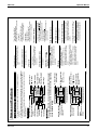
3
2
1
Enable/Disable setting
Condition setting
Holiday setting
Schedule timer
Operation Method
2/2
Ɣ Press
buttons to move the
buttons
highlighted item and press
to input the desired operation start time.
buttons moves the
Each press of
numbers by 1 hour or 1 minute.
Holding down the button causes the
number to change continuously.
The schedule timer can accept a maximum of
5 operations per day.
Ɣ Press
buttons to select the day to
be set on the condition setting screen.
Ɣ Input the program for the selected day
next.
Ɣ Display the schedule timer settings
screen. (See page 35.)
Ɣ Press
buttons to select
Condition setting on the schedule timer
settings screen.
Press Menu/Enter button to display the
condition setting screen.
Schedule timer
Condition setting
Menu Manipulation
English
Return
Monday
Operation
28°C
–
–
–
–
Operation
28°C
–
–
–
–
Setting
Time
06:00
––:––
––:––
––:––
––:––
Setting
Time
06:00
––:––
––:––
––:––
––:––
Schedule timer
Return
Monday
Operation
22°C
–
–
–
–
Setting
Time
06:00
––:––
––:––
––:––
––:––
Schedule timer
Return
Monday
Operation
22°C
–
–
–
–
Setting
Time
06:00
––:––
––:––
––:––
––:––
Schedule timer
Return
Monday
Schedule timer
2/6/2009 5:50:07
01_EN_3P243520-1.indd
PM
37
English
4
*1
*
*2
20°C-26°C
*3
OFF
Ɣ To change the set temperature, press
the Menu/Enter button so that the set
temperature will be highlighted and
ready to be changed.
buttons to change the set
Ɣ Press
temperature.
The set temperature will increase by 1°C
when the button is pressed and
decrease by 1°C when the button is
pressed.
Ɣ Pressing Menu/Enter button enters the
set temperature change.
Ɣ To make an operation change at set
buttons to move
temperature, press
the highlighted item and press
buttons to set the operation to 22°C .
22°C
—
The display changes in sequence as shown below
buttons are pressed.
when
The following three types of operations are
available.
*1. switch on the installation at a scheduled time,
in combination with a set point (exact
temperature control)
*2. switch on the installation at a scheduled time,
in limit operation
*3. switch off the installation (end of control)
* The status remain unchanged in the case of “–”.
Ɣ Press
buttons to move the
buttons
highlighted item and press
to select the desired operation.
2/6/2009 5:50:07 PM
37
Operation Manual
ED72-975
BRC1E61
3P243520-1
Return
Monday
Operation
28°C
20°C– 28°C
–
–
–
Operation
28°C
22°C– 28°C
–
–
–
Setting
Time
06:00
12:30
––:––
––:––
––:––
Setting
Time
06:00
12:30
––:––
––:––
––:––
Schedule timer
Return
Monday
Operation
28°C
20°C– 26°C
–
–
–
Setting
Time
06:00
12:30
––:––
––:––
––:––
Schedule timer
Return
Monday
Operation
28°C
20°C–26°C
–
–
–
Setting
Time
06:00
12:30
––:––
––:––
––:––
Schedule timer
Return
Monday
Operation
28°C
20°C–26°C
–
–
–
Setting
Time
06:00
12:30
––:––
––:––
––:––
Schedule timer
Return
Monday
Schedule timer
01_EN_3P243520-1.indd 38
38
5
Ɣ Pressing Menu/Enter button enters the
set temperature change.
Note
Ɣ The difference between the maximum and minimum
temperatures cannot be set to less than 6°C.
(* Maximum temperature – Minimum temperature 6°C)
Ɣ Press
buttons to change the set
temperature.
The set temperature will increase by 1°C
when the button is pressed and
decrease by 1°C when the button is
pressed.
Ɣ Press
buttons to select the desired
temperature to be changed.
Ɣ To change the maximum and minimum
temperatures, press the Menu/Enter
button so that the temperatures will be
ready to be changed.
Ɣ To make limit operation settings, press
buttons to move the highlighted
item and press
buttons to input the
desired set time.
buttons to move the
Ɣ Press
buttons
highlighted item and press
to set the operation to 20°C - 26°C .
Menu Manipulation
English
Operation
28°C
22°C– 28°C
OFF
–
–
Return
Yes
Setting
No
Is it settled by setting?
Setting
Time
06:00
12:30
15:00
––:––
––:––
Schedule timer
Return
Monday
Operation
28°C
22°C– 28°C
OFF
–
–
Setting
Time
06:00
12:30
15:00
––:––
––:––
Schedule timer
Return
Monday
Schedule timer
2/6/2009 5:50:07
01_EN_3P243520-1.indd
PM
39
English
8
7
6
Ɣ Press
button to select Yes on the
settings confirmation screen.
Pressing Menu/Enter button enters the
schedule timer settings and takes you
back to the basic screen.
Ɣ When the entire day settings are
completed, highlight the items other than
the operation and press the Menu/Enter
button.
The settings confirmation screen will
appear.
* To copy the settings for the previous day, select
the operation mode selector button so that the
settings will be copied as they are.
Example: The contents for Monday are copied by
pressing the operation mode selector
button after selecting Tuesday.
Ɣ To set a different day of the week, press
buttons to highlight the day
presently set.
buttons to change the day
Ɣ Press
and input the program in the same
manner.
Ɣ To make operation stop settings, press
buttons to move the highlighted
item and press
buttons to input the
desired operation stop time.
buttons to move the
Ɣ Press
buttons
highlighted item and press
to turn OFF the operation.
2/6/2009 5:50:08 PM
39
ED72-975
Operation Manual
29
30
3P243520-1
BRC1E61
Setting
Setting
Setting
Return
Yes
Setting
No
Is it settled by setting?
Schedule timer
Return
Sun Mon Tue Wed Thu Fri Sat
Holiday setting
Multi selection possible
Schedule timer
Return
Sun Mon Tue Wed Thu Fri Sat
Holiday setting
Multi selection possible
Schedule timer
Return
Enable/Disable setting
Condition setting
Holiday setting
Schedule timer
01_EN_3P243520-1.indd 40
40
4
3
2
1
Operation Method
Ɣ Press
button to select Yes on the
settings confirmation screen.
Pressing Menu/Enter button enters the
holiday settings and takes you back to
the schedule timer settings screen.
Ɣ To complete the holiday settings, press
Menu/Enter button.
The settings confirmation screen will
appear.
Note: To able the schedule timer for the day
selected as a holiday, the holiday setting
must be released.
Ɣ Press
buttons to select the desired
day.
buttons to display “ ” to
Press
make the holiday settings.
buttons switches the
Pressing
setting between set and release.
Multiple days can be selected as
holidays.
Ɣ Bring up the schedule timer settings
screen. (See page 35.)
Ɣ Press
buttons to select
Holiday setting on the schedule timer
settings screen.
Press Menu/Enter button to display the
holiday settings screen.
Operation
–
–
–
–
–
Setting
Time
––:––
––:––
––:––
––:––
––:––
English
3
2
Setting
Setting
Return
Yes
Setting
No
Is it settled by setting?
Schedule timer
Return
Disable
Enable/Disable setting
Schedule timer
Return
Enable/Disable setting
Condition setting
Holiday setting
Schedule timer
Operation Method
1
Ɣ Holiday that are set will be displayed on
the condition settings screen.
Ɣ Press
button to select Yes on the
settings confirmation screen.
Pressing Menu/Enter button enters the
enable/disable settings for the schedule
timer and takes you back to the basic
screen.
Ɣ Press
buttons to select Enable or
Disable on the enable/disable settings
screen.
Press Menu/Enter button after selecting
the item. Then the settings confirmation
screen will appear.
Ɣ Bring up the schedule timer settings
screen. (See page 35.)
Ɣ Press
buttons to select
Enable/Disable setting on the schedule
timer settings screen.
Press Menu/Enter button to display the
enable/disable settings screen.
Enabling or disabling the schedule timer without
changing the set day or time
Return
Sunday
Holiday
Schedule timer
2/6/2009 5:50:08
01_EN_3P243520-1.indd
PM
41
English
(The schedule timer will be disabled for days that have been set as holiday.)
Holiday setting
Menu Manipulation
2/6/2009 5:50:09 PM
41
Operation Manual
ED72-975
BRC1E61
3P243520-1
Setting
Setting
Setting
Return
Yes
Setting
No
Is it settled by setting?
Off reminder Timer
Return
minutes.
60
Each time after pressing
the operation button,
automatically stops after
Off reminder Timer
Return
Enable/ Disable setting
Condition setting
Off reminder Timer
Return
01_EN_3P243520-1.indd 42
42
4
3
2
1
Schedule timer
Off reminder Timer
Timer setting
Operation Method
Disable
Disable
Ɣ Press
button to select Yes on the
settings confirmation screen.
Pressing Menu/Enter button enters the
off reminder timer settings and takes
you back to the basic screen.
Ɣ Use
buttons to set the time from
operation start until the unit
automatically stops.
Selections can be made in increments of
10 minutes from 30 to 180 minutes.
Holding down the button causes the
number to change continuously.
Ɣ Select the desired time and press Menu/
Enter button.
The settings confirmation screen will
appear.
Ɣ Press
buttons to select
Condition setting on the off reminder
timer settings screen.
Press Menu/Enter button to display the
condition settings screen.
Ɣ Press
buttons to select the
Off reminder timer on the timer settings
screen.
Press Menu/Enter button to display the
off reminder timer settings screen.
(See page 34.)
Ɣ Bring up the timer settings screen.
English
3
2
1
Setting
Setting
Return
Yes
Setting
No
Is it settled by setting?
Off reminder Timer
Return
Disable
Enable/ Disable setting
Off reminder Timer
Return
Enable/ Disable setting
Condition setting
Off reminder Timer
Operation Method
Ɣ Press
button to select Yes on the
settings confirmation screen.
Pressing Menu/Enter button enters the
enable/disable settings for the off
reminder timer settings and takes you
back to the basic screen.
Ɣ Press
buttons to select Enable or
Disable on the enable/disable settings
screen.
Press Menu/Enter button after selecting
the item. Then the settings confirmation
screen will appear.
Ɣ Bring up the off reminder timer settings
screen. (See page 42.)
Ɣ Press
buttons to select
Enable/Disable setting on the off
reminder timer settings screen.
Press Menu/Enter button to display the
enable/disable settings screen.
Enabling or disabling the off reminder timer without
changing the set time
2/6/2009 5:50:09
01_EN_3P243520-1.indd
PM
43
English
Making and checking the off reminder timer settings
Menu Manipulation
2/6/2009 5:50:10 PM
43
ED72-975
Operation Manual
31
32
3P243520-1
BRC1E61
Setting
Return
Indoor unit
Outdoor unit
Setting
–––/000
–––/000
Contact address
0123–456–7890
Service Contact/Model Info
Return
01_EN_3P243520-1.indd 44
44
2
1
Set temp mode changeover
Airflow Direction
Quick Cool/Heat On/Off
Ventilation
Timer setting
Service Contact/Model Info
MainMenu
Operation Method
1/2
* The error code record may also appear.
If it is not blinking, the unit is working properly.
The error code record will disappear if you press
On/Off button for more than 4 seconds.
* The model name will not appear if you have had
the circuit board replaced.
(For some models the product code may appear. )
Ɣ The model information of the indoor and
outdoor units of your product will appear
on the bottom of the screen.
(If you have not yet registered your product, it will
not appear. )
Ɣ The phone number for the contact
address will appear at the top of the
screen.
Ɣ Press
buttons to select
Service Contact/Model Info on the
main menu screen and press Menu/
Enter button.
(See page 26.)
Ɣ Display the main menu screen.
Display method for service contact and model
information
Service Contact/Model Information
Menu Manipulation
English
Setting
Setting
Return
Adjusts contrast
Setting
Light
Dark
Contrast adjustment
Return
Contrast adjustment
Display changeover
Convenient functions
Return
Convenient functions
Setting status list
Clock setting
Language changeover
MainMenu
2/6/2009 5:50:10
01_EN_3P243520-1.indd
PM
45
English
3
2
1
Operation Method
2/2
Ɣ On the contrast adjustment settings
buttons until you reach
screen press
the desired contrast.
After setting, press Menu/Enter button
and return to the basic screen.
Ɣ Bring up the convenient functions
settings screen.
buttons to select
Ɣ Press
Contrast adjustment on the convenient
functions settings screen.
Press Menu/Enter button to display the
contrast adjustment settings screen.
Ɣ Press
buttons to select
Convenient functions on the main
menu screen.
Press Menu/Enter button to display the
convenient functions settings screen.
(See page 26.)
Ɣ Display the main menu screen.
Contrast Adjustment
Convenient Functions
2/6/2009 5:50:10 PM
45
Operation Manual
ED72-975
BRC1E61
3P243520-1
Setting
Setting
Return
Display
Setting
Standard
Display changeover
Return
Display
Desired disp select
Display changeover
Return
Contrast adjustment
Display changeover
01_EN_3P243520-1.indd 46
46
3
2
1
Convenient functions
Operation Method
Standard
None
* Refer to Setting the detailed display selection
to change detailed display selection.
(See page 47.)
Ɣ Press
buttons to select Standard
or Details on the display settings
screen.
Ɣ Then, press Menu/Enter button to
confirm settings and return to the basic
screen.
Ɣ Press
buttons to select Display on
the convenient functions settings
screen.
Press Menu/Enter button to display the
display settings screen.
Ɣ Bring up the convenient functions
settings screen. (See page 45.)
Ɣ Press
buttons to select
Display chageover on the convenient
functions settings screen.
Press Menu/Enter button to display the
display selection settings screen.
Display chageover
Display selection
Menu Manipulation
English
Setting
Return
Setting
None
Desired disp select
Display changeover
Return
Display
Desired disp select
Display changeover
2/6/2009 5:50:11
01_EN_3P243520-1.indd
PM
47
English
2
1
Operation Method
Standard
None
buttons displays the following.
Ɣ After setting, press Menu/Enter button
to confirm settings and return to the
basic screen.
2/6/2009 5:50:11 PM
47
Outdoor temperature
.......... An estimate of the temperature near
the outdoor unit.
The temperature that is detected may
be affected by factors such as the
location of the unit (if it is in direct
sunlight, for e.g.) and unit operation
during defrosting.
Room temperature
.......... An estimate of the temperature near
the remote controller.
The temperature that is detected may
be affected by the location of the unit.
Ɣ Be sure to read the following notes regarding display
of room temperature and outdoor temperature.
* Some models may not display these items even if they are selected.
Room temperature
* Outdoor temperature
* System
None
Ɣ Pressing
Ɣ Bring up the display selection settings
screen. (See page 46.)
Ɣ Press
buttons to select
Desired disp select on the convenient
functions settings screen.
Press Menu/Enter button to display the
detailed display selection screen.
Setting the detailed display selection
ED72-975
Operation Manual
33
34
Return
Setting
1/2
Swing
Low
Auto
Disable
Disable
Standard
Airflow Direction
Ventilation rate
Ventilation mode
Schedule timer
Off reminder Timer
Display changeover
Setting
Setting status list
Return
Convenient functions
Setting status list
Clock setting
Language changeover
2/2
3P243520-1
BRC1E61
Return
Setting
Convenient functions
Setting status list
Clock setting
Language changeover
01_EN_3P243520-1.indd 48
48
1
MainMenu
Operation Method
2/2
Off reminder timer
Quick Cool/Heat
Display changeover
Desired disp select
* Display items may differ depending on the model.
Only the items that can be set are displayed.
Airflow direction
Ventilation rate
Ventilation mode
Schedule timer
Display items
Ɣ A list showing the current setting status
will appear.
buttons to go to the next item.
Press
Ɣ Pressing Cancel button takes you back
to the main menu screen.
Ɣ Press
buttons to select
Setting status list on the main menu
screen and press Menu/Enter button.
(See page 26.)
Ɣ Display the main menu screen.
Ɣ Display the main menu screen. (See page 26.)
Ɣ Press
buttons to select
Clock setting on the main menu
screen.
Press Menu/Enter button to display the
clock settings screen.
Setting the clock
Clock Setting
2
1
MainMenu
Operation Method
Manipulating the setting status list
Setting Status List
Menu Manipulation
English
Return
12:21
Year 2008
Month 10
Day
07
Tuesday
Clock setting
Return
12:00
Year 2008
Month 10
Day
07
Tuesday
Clock setting
Return
00:00
Year 2008
Month 10
Day
07
Tuesday
Clock setting
Return
00:00
Year 2008
Month 10
Day
01
Tuesday
Clock setting
Return
00:00
Year 2008
Month 01
Day
01
Tuesday
Clock setting
2/6/2009 5:50:12
01_EN_3P243520-1.indd
PM
49
English
6
5
4
3
2
Setting
Setting
Setting
Setting
Setting
The date can be set between
January 1, 2008 and December 31, 2099.
Note:
Ɣ Select “Minute” with
buttons.
buttons.
Input the minute with
Holding down the button causes the
number to change continuously.
Ɣ Press Menu/Enter button.
The settings confirmation screen will
appear.
Ɣ Select “Hour” with
buttons.
buttons.
Input the hour with
Holding down the button causes the
number to change continuously.
Ɣ Select “Day” with
buttons.
buttons.
Input the day with
Holding down the button causes the
number to change continuously.
Days of the week change automatically.
Ɣ Select “Month” with
buttons.
buttons.
Input the month with
Holding down the button causes the
number to change continuously.
Ɣ Select “Year” with
buttons.
buttons.
Input the year with
Holding down the button causes the
number to change continuously.
2/6/2009 5:50:12 PM
49
Operation Manual
ED72-975
BRC1E61
Return
Yes
Setting
No
* When setting schedule timer, the display return to
the settings screens.
Ɣ Press
button to select Yes on the
settings confirmation screen.
Press Menu/Enter button to set the clock
and return to the basic screen.
3P243520-1
Setting
Return
Setting
English
Selectable languages
Language changeover
Return
Convinient functions
Setting status list
Clock setting
Language changeover
MainMenu
01_EN_3P243520-1.indd 50
50
2
1
Operation Method
2/2
Ɣ Press
buttons to select “Language”
on the language changeover screen.
English/Deutsch/Français/Español/
Italiano/EȜȜȘȞȚțȐ/Nederlands/
Portugues/PyccƸɢɣ/Ɍürkçe
Ɣ Pressing Menu/Enter button to confirm
settings and return to the basic screen.
Ɣ Press
buttons to select
Language changeover on the main
menu screen and press the Menu/Enter
button.
(See page 26.)
Ɣ Display the main menu screen.
Selectable languages
Language changeover
7
Is it settled by setting?
English
Return
Cool
Return
1/2
Clean the filter
28°C
Set temperature
Setting
Filter Sign Reset
Set temp mode changeover
Airflow Direction
Quick Cool/Heat On/Off
Ventilation
Timer setting
MainMenu
28°C
Set temperature
Clean the filter
Cool
2/6/2009 5:50:13
01_EN_3P243520-1.indd
PM
51
English
3
2
1
Operation Method
Ɣ The display shown in 1 will disappear
from the basic screen when the filter
sign is reset.
Ɣ Press
buttons to select
Filter Sign Reset on the main menu
screen and press Menu/Enter button.
Ɣ Reset the filter sign when the filter or
element is washed, cleaned, or replaced.
Ɣ Press Menu/Enter button.
The main menu screen will appear.
Ɣ Wash, clean, or replace the filter or
element.
For details, refer to the operation
manual of the indoor unit.
2/6/2009 5:50:13 PM
51
Ɣ When the time to clean the filter or element has
come, one of the following messages will appear on
the bottom of the basic screen.
“Clean the filter”
“Clean the filter and element”
“Clean the element”
Filter Sign Resetting
Maintenance
6.6
Clock setting
Menu Manipulation
ED72-975
Operation Manual
Maintenance
35
36
Ɣ Be sure to stop the operation of
the air conditioner and turn off
the power supply breaker at the
time of maintenance.
Failure to do so may result in
electric shocks or injury.
3P243520-1
BRC1E61
01_EN_3P243520-1.indd 52
52
Ɣ Do not use flammable materials (e.g., hairspray or insecticide) near the air
conditioner.
Do not clean the product with organic solvents such as benzine or paint
thinner.
The use of organic solvents may cause crack damage to the product, electric shocks,
or fire.
Warning
Note
Ɣ Do not use any paint thinner, organic solvent, or strong acid.
English
2
1
28°C
Set temperature
Return
Indoor unit
Outdoor unit
Contact address
0123–4567–8900
Error code:A1
Setting
–––/000
–––/000
Error : Press Menu Button
Cool
Operation Method
Ɣ The error code blinks and the contact
address and model name will appear.
Ɣ Notify your Daikin dealer of the Error
code and Model name.
Ɣ Press Menu/Enter button.
* The operation indicator will not blink.
“Warning: Press Menu Button.”
* The operation indicator will blink.
“Error: Press Menu Button.”
Ɣ If an error occurs, either one of the following
items will blink in the basic screen.
53
2/6/2009 5:50:14 PM
Operation
lamp
Continued operation under such circumstances may result in failure, electric shocks, or fire.
Contact your Daikin dealer.
Ɣ When the air conditioner is malfunctioning (e.g., giving off a burning odor),
stop the air conditioner and turn off power.
Warning
Contact your Daikin dealer in the following cases
2/6/2009 5:50:14
01_EN_3P243520-1.indd
PM
53
English
Ɣ Wipe the LCD and other surface part of the remote controller with a dry cloth when they become
dirty.
Ɣ If the dirt on the surface cannot be removed, soak the cloth in neutral detergent diluted with
water, squeeze the cloth tightly, and clean the surface. Wipe the surface with a dry cloth then.
Maintenance of Unit and LCD
Ɣ Do not wash the remote
controller.
Doing so may cause electric
leakage and result in electric shocks
or fire.
Error code Display
Useful Information
6.7
Caution
Maintenance
Operation Manual
ED72-975
Useful Information
BRC1E61
Improper installation may result in
electric shocks or fire.
Consult your Daikin dealer.
Ɣ Do not relocate or reinstall the
remote controller by yourself.
3P243520-1
01_EN_3P243520-1.indd 54
54
Contact your Daikin dealer.
Inquiry about After-sale Service
Consult your Daikin dealer.
Fair-paying services may be possible at the request of the customer.
(The warranty period is one year counting from the date of installation.)
Repairs after Warranty Period
2/6/2009 5:50:14 PM
English
The relocation of the remote controller requires special technology. Consult your Daikin dealer.
Actual expenses required for the relocation of the remote controller will be charged.
Relocation
Ɣ Model name
Ɣ Date of installation
Ɣ Failure conditions: As precise as possible.
Ɣ Your address, name, and telephone number
Advise the repairer of the following items
Ɣ Do not disassemble, modify, or
repair the unit.
Doing so may result in electric
shocks or fire.
Consult your Daikin dealer.
Warning
After-sale Service
Useful Information
ED72-975
Operation Manual
37
38
3P243521-1
BRC1E61
01_EN_3P243521-1.indd 1
English
Failure to follow these instructions properly may result in personal
injury or loss of life.
Failure to observe these instructions properly may result in property
damage or personal injury, which may be serious depending on the
circumstances.
2
2/3/2009 1:19:14 PM
English
Ask your dealer or qualified personnel to carry out installation work.
Do not attempt to install the remote controller yourself. Improper installation may result in water
leakage, electric shocks or fire.
Consult your local dealer regarding relocation and reinstallation of the remote controller.
Improper installation work may result in leakage, electric shocks or fire hazards.
Install the remote controller in accordance with the instructions in this installation manual.
Improper installation may result in water leakage, electric shocks or fire.
Be sure to use only the specified accessories and parts for installation work.
Failure to use the specified parts may result in the unit falling, water leaakage, electric shocks or fire.
Install the remote controller on a foundation strong enough to withstand the weight of the remote
controller.
A foundation of insufficient strength may result in the remote controller falling and causing injury.
Electrical work must be performed in accordance with relevant local and national regulations and
with instructions in this installation manual.
Be sure to use a dedicated power supply circuit only. Insufficiency of power circuit capacity and
improper workmanship may result in electric shocks or fire.
Always perform installation work with the power supply shut-off.
Touch with energized electric parts causes an electric shock.
Do not disassembly, reconstruct or repair.
Electric shock and/or fire are caused.
Make sure that all wiring is secured, the specified wires are used, and that there is no strain on the
terminal connections or wires.
Improper connections or securing of wires may result in abnormal heat build-up or fire.
The choice of materials and installations must comply with the applicable national and international
standards.
WARNING
Ɣ After completing installation, conduct a trial operation to check for faults and explain to the customer
how to operate the air conditioner and take care of it with the aid of the operation manual. Ask the
customer to store the installation manual along with the operation manual for future reference.
CAUTION
WARNING
2/3/2009 1:19:14
01_EN_3P243521-1.indd
PM
2
1
12. Language changeover .................... 22
11. Clock Setting ................................... 22
10. Confirmation of registered
details ............................................... 21
9. Registration method of the
service contract .............................. 20
8. Checking procedure of
error record ..................................... 19
7. Test operation method
(in the case of SkyAir) .................... 16
6. Field setting method ....................... 13
5. Power-on .......................................... 12
4. Functions and menu items
of remote controller buttons .......... 10
3. Remote controller installation
procedure .......................................... 4
2. Accessories ....................................... 4
Ɣ The precautions described herein are classified as WARNING and CAUTION. They both contain
important information regarding safety. Be sure to observe all precautions without fail.
Please read these “Safety Precautions” carefully before installing air conditioning
equipment and be sure to install it correctly.
Also see installation manual attached to the indoor unit.
1. Safety Precautions
7.1
1. Safety Precautions ............................ 2
Contents
Installation Manual
ED72-975
7. Installation Manual
Safety Precautions
BRC1E61
3P243521-1
01_EN_3P243521-1.indd 3
English
3
(M4×16)
(2 pcs.)
(φ3.5×16)
(2 pcs.)
Operation
manual
(1 pc.)
Clamp
(1 pc.)
(1 pc.)
Installation
manual
Safety Precautions” when determining the location.
(1 pc.)
Wiring retainer
Through
hole
F8-10
4
48.5
If the hole size is too large or the location is not
proper, the hole may come out from the controller.
CAUTION
Set the center of the wall hole
to the center of the wiring thro
ugh hole on the controller
lower case when making the
hole.
Take care that dust or moisture does
not touch the PC-board of removed
upper case.
Remote controller PC-board is
installed on the upper case. Take care
not to damage the PC-board with the
screwdriver.
Insert and twist the screwdriver
lightly for removal.
Screwdriver
2/3/2009 1:19:15 PM
English
Lower case
Upper case
Insert a screwdriver in the recess of lower case to remove the upper case (2 points).
3-3 Remove upper case.
Lower case
Through hole
F8-10
External view of the remote controller
3-2 Make a wiring through hole on the wall if the wires are taken
out from the back side.
Make sure to follow “ 1.
3-1 Determine where to install the remote controller.
3. Remote controller installation
procedure
Small screw
Wood screw
The following accessories are included.
2/3/2009 1:19:14
01_EN_3P243521-1.indd
PM
4
To avoid leakage and electric shock due to entry of water or insects, fill the wiring through hole with
putty.
To avoid electric shocks, do not operate with wet hands.
Do not wash the remote controller with water, as this may result in electric shocks or fire.
Install the indoor and outdoor units, power cord and connecting wires at least 1 meter away from
televisions or radios to prevent picture interference and noise.
(Depending on the incoming signal strength, a distance of 1 meter may not be sufficient to eliminate
noise.)
Do not install the air conditioner in the following locations:
1. Where there is a high concentration of mineral oil spray or vapour (e.g. a kitchen).
Plastic parts will deteriorate, parts may fall off and water leakage could result.
2. Where corrosive gas, such as sulphurous acid gas, is produced.
Corroding of copper pipes or soldered parts may result in refrigerant leakage.
3. Near machinery emitting electromagnetic radiation.
Electromagnetic radiation may disturb the operation of the control system and result in a
malfunction of the unit.
4. Where flammable gas may leak, where there is carbon fibre or ignitable dust suspensions in the
air, or where volatile flammables such as paint thinner or gasoline are handled.
Operating the unit in such conditions may result in fire.
5. High temperature area or directly flamed point.
Heating and/or firing may be caused.
6. Moist area, or place where may be exposed to water.
If water enters inside of the remote controller, electric shock may be caused and inner electronics
may fail.
When remote controller thermo function is used, select the installation location considering the
followings.
Ɣ A place where average temperature in the room can be detected.
Ɣ A place where is not exposed to direct sunlight.
Ɣ A place where is far apart from heat source.
Ɣ A place where is not affected by outside air due to door opening/closing or the like.
2. Accessories
7.2
7.3
40
CAUTION
ED72-975
Installation Manual
Accessories
Remote controller installation procedure
39
40
3-4-4 Upper center outlet
Cut off thin area (hatched area) with nippers
or the like, and then remove burr with a file or
the like.
3-4-3 Upper outlet
Cut off thin area (hatched area) with nippers
or the like, and then remove burr with a file or
the like.
CAUTION
3P243521-1
BRC1E61
01_EN_3P243521-1.indd 5
English
Sheathed vinyl cord or cable (2 wire) (NOTE)
0.75-1.25mm²
6
Clamp
Clamp
Secure the wiring at
the wiring fixing point
by using attached
clamping material.
-
Lower case
Cross-section
Indoor unit
P1 P2
<Wiring fixing guideline>
PC-board
Ground the shielded
part on the indoor
unit side. (NOTE.1)
1) Shield wire (2 wire) can be used for remote controller wiring, but it must
confirm to EMC (Electromagnetic Compatibility) (Australian regulation)
NOTE
Wiring fixing
point
Upper case
3-5-1 Back outlet
2/3/2009 1:19:17 PM
English
.
Connect the terminals (P/P1, N/P2) of the remote controller upper case with the terminals (P1, P2)
of the indoor unit. (P1 and P2 have no polarities.)
Sheath stripping length:
Ɣ Ca. 150mm for upper outlet
Ɣ Ca. 200mm for upper center outlet
Cutting guideline
of the wiring
Peel the shield and sheath
Ca. 10mm
For easy wiring, it is better to
keep ca. 10mm difference
between the length of two wires.
Sheath part in the remote controller case should be stripped.
2/3/2009 1:19:16
01_EN_3P243521-1.indd
PM
6
Shield wire (2 wire) can be used for remote controller wiring, but it must confirm to EMC
(Electromagnetic Compatibility) (Australian regulation)
NOTE
Wiring Type
Wiring Size
Wiring Specifications
1. Switch box and transmission wiring are not attached.
2. Do not directly touch the remote controller PC-board.
5
Cut off thin area (hatched area) with nippers
or the like, and then remove burr with a file or
the like.
Cut off resin area (hatched area).
3-5 Conduct wiring.
3-4-2 Left outlet
3-4-1 Back outlet
3-4 Determine the direction of controller wiring outlet (back
outlet, left outlet, upper center outlet, upper outlet).
Installation Manual
ED72-975
BRC1E61
PC-board
3P243521-1
01_EN_3P243521-1.indd 7
English
Upper case
-
PC-board
Wiring retainer
Ground the shielded
part on the indoor
unit side. (NOTE.1)
Indoor unit
P1P2
Lower case
Lower case
Lower case
Install attached
wiring retainer to
prevent wiring pinch
according to left
figure.
Upper case
Indoor unit
P1P2
Ground the
shielded part on
Indoor unit
the indoor unit
P1P2
side. (NOTE.1)
Cross-section
Wiring
Wiring retainer
PC-board
3-5-4 Upper center outlet
Upper case
Wiring retainer
3-5-3 Upper outlet
Upper case
Ground the shielded
part on the indoor
unit side. (NOTE.1)
8
Switch box
(field supply)
(Use optional accessory
KJB211A)
Small screws (M4×16)
Secure by using attached small screws (2 pcs.).
(Installation pitch)
46
English
2/3/2009 1:19:18 PM
Switch box for two units
(with no cover)
3-6-2 In the case of installation on the switch box
Wood screws
(F3.5×16)
Secure by using attached wood screws (2 pcs.).
3-6-1 In the case of installation on the wall
In the case of wiring center upward drawing or rearward drawing, see wiring procedure first as
wiring with the case is needed before fixing.
3-6 Fixing procedure of lower case.
2/3/2009 1:19:17
01_EN_3P243521-1.indd
PM
8
7
CAUTION
Ɣ Perform wiring apart from a power line not to receive electrical noise (external noise)
during the wiring.
Ɣ Seal wiring draw-in port securely with putty (field supply) to prevent entry of insects or
the like.
84
3-5-2 Left outlet
ED72-975
Installation Manual
41
42
84
3P243521-1
BRC1E61
01_EN_3P243521-1.indd 9
English
9
10
∗Depending on connected model
Set temp mode changeover
Airflow Direction
Quick Cool/Heat On/Off
Ventilation
Timer setting
Service Contact/Model Info
Convenient functions
Setting status list
Clock setting
Language changeover
Main menu
(3) Menu/Enter button
Ɣ Used to indicate the main menu.
(For details of main menu, see the
operation manual.)
Ɣ Used to enter the setting item selected.
(2) Fan speed control button
Used to change the fan control.
(1) Operation mode selector button
Used to change the mode.
2/3/2009 1:19:19
01_EN_3P243521-1.indd
PM
10
Ɣ Align the upper case with tabs of the lower case (6 points), inset and install the upper case.
Ɣ Install the wiring with care to prevent the pinch.
Ɣ Peel off a protective seal which is attached on the upper case.
3-7 Install the upper case as original condition.
Ɣ Select flat place for installation face as possible.
Ɣ And, do not tighten the installation screws too much not to deform the lower case.
CAUTION
28
(Installation pitch)
4-1 Functions and menu items
2/3/2009 1:19:19 PM
English
(6) Right button
Ɣ Used to highlight the next items on the
right-hand side.
Ɣ Display contents are changed to next
screen per page.
(5) Down button
Ɣ Used to lower the set temperature.
Ɣ The next items on the lower side will be
highlighted.
(The highlighted items will be scrolled
continuously when the button is kept
pressed.)
Ɣ Used to change the item selected.
(4) Up button
Ɣ Used to raise the set temperature.
Ɣ The next items on the upper side will be
highlighted.
(The highlighted items will be scrolled
continuously when the button is kept
pressed.)
Ɣ Used to change the item selected.
(2) Fan speed control button
(10) Cancel button
(3) Menu/Enter button
(8) On/Off button
(9) Operation lamp
(4) Up button
(5) Down button
(6) Right button
(7) Left button
(11) LCD (with backlight)
(1) Operation mode selector button
4. Functions and menu items of remote
controller buttons
7.4
Small screws (M4×16)
Switch box
(field supply)
(Use optional accessory
KJB111A)
Switch box for one unit
(with no cover)
Installation Manual
ED72-975
Functions and menu items of remote controller buttons
BRC1E61
∗Depending on connected model
3P243521-1
01_EN_3P243521-1.indd 11
English
Return
Setting
Test operation ON/OFF
Register Service Contract
Field setting list
Group No. setting
Indoor unit Airnet No. set
Outdoor unit Airnet No. set
Field setting
1/2
<Field setting menu screen>
In the highlighted display (selected items)
setting screen, button operation
descriptions are displayed.
Highlighted display (selected items)
4-2 Displays for button operation descriptions
11
12
5-2
5-1
28°C
Set temperature
Return
Press the menu button
Fan
<Basic screen>
Main remote contrl
Connection under check
Please wait for a moment
Error code:U5
Main remote contrl
Connection under check
Please wait for a moment
Off reminder Timer
NOTE
When selecting a different language, refer to 12. Language
5-2
5-1
28°C
Set temperature
(See page 22.)
2/3/2009 1:19:20 PM
English
Return
Press the menu button
Fan
<Basic screen>
Sub remote contrl
Connection under check
Please wait for a moment
Press and hold 4 seconds
or longer the Operation
mode selector button of sub
remote controller side.
Main remote contrl
Connection under check
Please wait for a moment
Error code:U5
Main remote contrl
Connection under check
Please wait for a moment
Off reminder Timer
<Sub remote controller>
changeover.
<Main remote controller>
If sub remote controller is not set at power-on in the case
of one indoor unit controlled by two remote controllers,
“Error code: U5” is displayed in the connection checking
screen.
Select the sub remote controller by pressing the
Operation mode selector button of either one of the
remote controllers for 4 seconds or longer.
If the basic screen is not displayed more than 2 minutes
after “sub remote controller” display, shut off the power
supply and check the wiring.
CAUTION
5-2 Basic screen is displayed.
Be sure to set sub remote
controller during above display.
Press and hold 4 seconds or
longer the Operation mode
selector button of the remote
controller to be set.
When the display is changed from
main remote controller to sub
remote controller, the setting is
completed.
When 1 indoor unit is
controlled by 2 remote
controllers:
During above display, backlight
does not light by button operation.
power-on.
“Connection under check
Please wait for a moment”
5-1 Followings are displayed after
Ɣ Check for completion of indoor/outdoor units wiring.
Ɣ Check for closing of EL. COMPO. BOX cover of indoor and outdoor units before power-on.
5. Power-on
2/3/2009 1:19:20
01_EN_3P243521-1.indd
PM
12
Ɣ Operate the button during backlight lit.
However, On/Off may be operated concurrently with backlight lit.
Ɣ When 1 indoor unit is controlled by 2 remote controllers, a remote controller backlight
which is operated first light.
Ɣ To operate Up/Down/Left/Right button, always press of the button.
CAUTION
(11) LCD (with backlight)
The backlight will be light for
approximately 30 seconds by pressing
any operation button.
(10) Cancel button
Ɣ Used to return to the previous screen.
Ɣ Press and hold this button for 4 seconds
or longer to display field setting menu.
(9) Operation lamp
Green lamp lights up during operation. The
lamp will blink if an malfunction occurs.
Field setting menu
Test operation ON/OFF
Register Service Contract
Field setting list
Group No. setting
Indoor unit Airnet No. set
Outdoor unit Airnet No. set
Error record
Indoor status display
Outdoor status display
Fan forced operation ON
Main/Sub changeover
Filter element sign OFF
7.5
(8) On/Off button
Press once to operate, and press once
again to stop.
(7) Left button
Ɣ Used to highlight the next items on the
left-hand side.
Ɣ Display contents are changed to
previous screen per page.
ED72-975
Installation Manual
Power-on
43
44
3P243521-1
BRC1E61
01_EN_3P243521-1.indd 13
English
In the case of group total
setting, all of SECOND CODE
NO. which may be set are
displayed as “ ∗ ”. “ ∗ ” is
changed to SECOND CODE
NO. to be set. And, SECOND
CODE NO. “ - ” means no
function.
the FIRST CODE NO. to be
changed, and select desired
“SECOND CODE NO.” by using
(Up/Down) button. Multiple
identical mode number settings
are available.
6-5 Highlight SECOND CODE NO. of
In the case of individual setting
per indoor unit, current settings
are displayed. And, SECOND
CODE NO. “ - ” means no
function.
unit during group control (When
Mode No. such as 20 , 21 ,
22 , 23 , 25 are selected),
highlight the unit No. and select
“Indoor unit No.” to be set by
(Up/Down) button.
using
(In the case of group total setting,
this operation is not needed.)
6-4 In the case of setting per indoor
desired “Mode No.” by using
(Up/Down) button.
6-3 Highlight the mode, and select
field setting menu, and press
Menu/Enter button.
Field setting list screen is
displayed.
6-2 Select Field setting list in the
4 seconds or longer.
Field setting menu is displayed.
6-1 Press and hold Cancel button for
6-3
6-4
6-5
Press and hold Cancel
button for 4 seconds or
longer during backlight lit.
Return
Unit No
0
0–01
4–––
8–––
Setting
Mode
20
1–00
2–00
5–––
6–––
9–––
a–––
Setting
1/2
Setting
Mode
10
1– 2– 5–––
6–––
9–––
a–––
3– 7–––
b–––
11 (21)
10 (20)
Mode
No.
Note) 1
14
6-6
6-7
Yes
No
Setting
Setting confirmation
Press Menu/Enter button.
Return
Is it settled by setting?
Field setting list
<Setting confirmation screen>
Pair
3
Setting number of connected Sky Air
simultaneous operation system
indoor units (setting for simultaneous operations system)
Display
Spacing time of display time to
clean air filter count (setting for
when the filter sign is not to be
displayed)
0
Use
Thermostat sensor in remote
controller
Long-life
filter
Approx.
200 hrs.
Approx.
2.500 hrs.
Twin
Do not
display
Not use
Ultra-long
life filter
Approx.
100 hrs.
Approx.
1.250 hrs.
Approx.
5.000 hrs.
02
Triple
————
————
————
————
03
SECOND CODE NO. Note) 2
Approx.
10.000 hrs.
2
Standard
filter
Long life
filter
Ultra
long life
filter
01
Long-life filter type (setting of filter
sign indication time).
(Change setting when ultra-long
filter is installed)
Filter Contamination Heavy/Light
(Setting for spacing time
of display time to clean
air filter)
(Setting for when filter
contamination is heavy,
and spacing time of
display time to clean air
filter is to be halved)
Description of setting
1
0
FIRST
CODE
NO.
2/3/2009 1:19:21 PM
English
Double twin
————
————
————
————
04
Ɣ When an optional accessory is installed on the indoor unit, settings of the indoor unit may be
changed. See the manual of the optional accessory.
Ɣ For field setting details of the outdoor unit, see installation manual attached to the outdoor unit.
CAUTION
“Connection under check
Please wait for a moment” is
displayed for initialization. After
the initialization, the basic screen
returns.
6-10 Backlight goes out, and
pleted, press Cancel button
twice.
6-9 After all setting changes are com-
6-8 In the case of multiple setting
changes, repeat “6-3” to “6-7”.
Enter button. Setting details are
determined and field setting list
screen returns.
6-7 Select Yes and press Menu/
2/3/2009 1:19:21
01_EN_3P243521-1.indd
PM
14
13
FIRST CODE (SW) NO.
SECOND CODE NO.
Return
Unit No
0
0–01
4–––
8–––
Field setting list
Press Menu/Enter button.
3–00
7–––
b–––
6-3
6-5
In the case of group total
setting
<Field setting screen>
Press Menu/Enter button.
Return
Test operation ON/OFF
Register Service Contract
Field setting list
Group No. setting
Indoor unit Airnet No. set
Outdoor unit Airnet No. set
Field setting
In the case of individual
setting per indoor unit
6-2
Field setting list
28°C
Set temperature
Return
Press the menu button
Fan
<Field setting menu screen>
6-1
<Basic screen>
confirmation screen is displayed.
6-6 Press Menu/Enter button. Setting
Light
7.6
Heavy
6. Field setting method
Installation Manual
ED72-975
Field setting method
BRC1E61
Equipped
High air outlet velocity (for high
ceiling applications).
Selection of airflow direction (setting
for when a blocking pad kit has
been installed).
Selection of airflow function (setting
for when using a decoration panel
for outlet).
Airflow direction range setting.
Setting the external static pressure
(setting according to the connected
duct resistance) (for FHYK, follow
the high ceiling setting)
2
0
1
3
4
6
3
Not permitted
Level 2
Permission level setting
1
Home leave function
Not use
Thermostat sensor in remote
controller (for limit operation and
Home leave function only)
3
2
Equipped
Drain pump operation with
humidifying.
(Normal)
Normal
Upper
≤ 2.7m
1°C
Permitted
Level 3
Use
Not equipped
High static
pressure
(High ceiling)
Normal
Not equipped
3-way flow
> 2.7 ≥ 3.0m
0.5°C
ON/OFF
operation
02
————
————
————
————
Low static
pressure
————
Lower
————
2-way flow
> 3.0 ≥ 3.5m
————
————
03
SECOND CODE NO. Note) 2
————
————
————
————
————
————
————
————
————
————
————
————
04
3P243521-1
01_EN_3P243521-1.indd 15
English
16
field setting menu, and press Menu/
Enter button. Basic screen returns and
“Test operation” is displayed.
7-5 Select Test operation ON/OFF in the
4 seconds or longer. Field setting
menu is displayed.
7-4 Press and hold Cancel button for
using the remote controller.
7-3 Set the operation mode to cooling by
and gas are opened.
<Make sure that outer panel and
piping cover is closed before
operation (danger of electric
shock). >
∗ After air purge by vacuum pump,
refrigerant pressure may not rise
even though the stop valve is
opened. The reason is that refrigerant system of the outdoor unit is
blocked by electrical expansion valve
or the like. Operation is no problem.
7-2 Confirm that stop valves of both liquid
more than 6 hours before operation
start with front panel closed to protect
compressor.
7-1 Make sure to turn on the power supply
Return
Cool
Setting
28°C
Set temperature
<Basic screen>
7-5
Return
Setting
Test operation ON/OFF
Register Service Contract
Field setting list
Group No. setting
Indoor unit Airnet No. set
Outdoor unit Airnet No. set
Field setting
1/2
<Field setting menu screen>
7-3
7-4
2/3/2009 1:19:22 PM
English
Press Menu/Enter button.
Press and hold Cancel
button for 4 seconds or
longer during backlight lit.
Ɣ The backlight will be light for approximately
30 seconds by pressing any operation button.
Ɣ Operate the buttons during the backlight lit.
However, On/Off can be operated concurrently with the backlight lit.
Notes for backlight
Ɣ Check that wiring work of the indoor unit and the outdoor unit is completed.
Ɣ Check that EL. COMPO. BOX cover of the indoor unit and the outdoor unit is closed.
Ɣ After refrigerant piping, drain piping and electric wiring are completed, clean inside of the indoor unit
and decorative panel.
Ɣ Perform the test operation according to following procedure.
Also see installation manuals attached to the indoor unit and the outdoor
unit.
∗ In the case of VRV, see the manual attached to the outdoor unit.
7. Test operation method (in the case of
SkyAir)
2/3/2009 1:19:22
01_EN_3P243521-1.indd
PM
16
15
Notes) 1. Though setting is performed totally in the group, set Mode No. in the parenthesis when
individual setting per indoor unit or checking after the setting should be performed.
2. SECOND CODE NO. at factory shipment is set to “01”. However for the following cases it is
set to “02”.
Ɣ Airflow direction range setting (except round flow cassette)
Ɣ Thermostat sensor in remote controller (SkyAir only)
Ɣ Thermostat sensor in remote controller for limit operation and Home leave function only
Ɣ Home leave function
3. Any function which the indoor unit does not have is not displayed.
1e
1c
15 (25)
13 (23)
4-way flow
Thermostat differential changeover
(setting for when using remote
sensor).
Forced OFF
ON/OFF input from outside (setting
for when forced ON/OFF is to be
operated from outside).
1
01
Description of setting
FIRST
CODE
NO.
7.7
12 (22)
Mode
No.
Note) 1
ED72-975
Installation Manual
Test operation method (in the case of SkyAir)
45
46
3P243521-1
BRC1E61
01_EN_3P243521-1.indd 17
English
(If the operation is performed, the
indoor unit may be contaminated with
the materials which arise from paints or
adhesives during the interior work, and
water splash or water leak may occur.)
Ɣ If interior work is not completed after the
test operation finish, explain to the
customer that operation should not be
performed until the interior work completion to protect the indoor unit.
installed, shut off the power supply
after the test operation finishes.
7-13 When the decorative panel is not
operation manual.
7-12 Check the functions according to the
field setting menu, and press Menu/
Enter button. Basic screen returns and
normal operation is conducted.
7-11 Select Test operation ON/OFF in the
4 seconds or longer in the basic
screen.
Field setting menu is displayed.
7-10 Press and hold Cancel button for
is confirmed, press Menu/Enter button.
Basic screen returns.
7-9 After the operation of airflow direction
direction setting function, select
Airflow Direction in the main menu
and check that airflow direction is
actuated according to the setting.
For operation of airflow direction
setting, see the operation manual.
7-8 In the case of a model having airflow
screen. Main menu is displayed.
7-7 Press Menu/Enter button in the basic
operation can start as well.
7-6 in reverse order, test
tioned procedures 7-5 and
10 seconds. The test operation starts.
Check operation condition for
3 minutes.
∗ Note) In the case of above-men-
7-6 Press On/Off button within about
7-11
7-10
7-9
7-8
7-6
7-7
Setting
Setting
<Basic screen>
Return
1/2
28°C
Test operation ON/OFF
Register Service Contract
Field setting list
Group No. setting
Indoor unit Airnet No. set
Outdoor unit Airnet No. set
Field setting
Setting
1/2
Set temperature
Test Operation
Cool
Return
Swing
Airflow Direction
Return
Set temp mode changeover
Airflow Direction
Quick Cool/Heat On/Off
Ventilation
Timer setting
Service Contact/Model Info
MainMenu
<Main menu screen>
28°C
Set temperature
Test Operation
Cool
18
Checking
procedure of error record”.
confirmed, refer to “ 8.
Ɣ When the remote controller displays
any item in following table, inspect the
details in the table.
Ɣ If a error occurs, “code” is displayed in
the LCD like right figure.
Conduct the failure analysis referring to
“Error code list” in the installation
manual of the indoor unit.
And when the unit No. which detected
the error during group control is
Failure diagnosis method
conduct the failure diagnosis referring
to <Error code list> in the installation
manual of the indoor unit.
After the failure diagnosis finishes,
press and hold On/Off button for
4 seconds or longer in the “Service
Contact/Model Info” screen to erase
the error code record.
7-17 If the error code record is displayed,
screen is displayed. Check that error
code record is not displayed in the
screen.
∗ Screen which does not display the
error code record means normal
status.
7-16 Service Contact/Model Information
the main menu, and press Menu/Enter
button.
7-15 Select Service Contact/Model Info in
screen. Main menu screen is displayed.
7-14 Press Menu/Enter button in the basic
2/3/2009 1:19:22
01_EN_3P243521-1.indd
PM
18
17
Press Menu/Enter button.
Press and hold Cancel
button for 4 seconds or
longer during backlight lit.
Press Menu/Enter button.
Change the airflow
direction by using
(Up/Down)button.
Press Menu/Enter button.
Press Menu/Enter button.
Press On/Off button
(within 10 seconds).
CAUTION
7-16
7-17
7-15
7-14
Setting
28°C
Set temperature
1/2
28°C
Set temperature
Setting
–––/000
–––/000
Setting
Test Operat. CODE : U5
Cool
Return
Indoor unit
Outdoor unit
Contact address
0123–4567–8900
Error code:U5
Return
Set temp mode changeover
Airflow Direction
Quick Cool/Heat On/Off
Ventilation
Timer setting
Service Contact/Model Info
MainMenu
<Main menu screen>
Return
Cool
<Basic screen>
2/3/2009 1:19:23 PM
English
Press and hold On/Off
button for 4 seconds or
longer during backlight lit.
Press Menu/Enter button.
Press Menu/Enter button.
Ɣ If operation is not available due to any malfunction, refer to following Failure diagnosis method .
Ɣ After the test operation finishes, check that error code record is not displayed in the Service
Contact/Model Information screen of the main menu according to the following procedure.
Installation Manual
ED72-975
BRC1E61
Ɣ Indoor PC-board assembly failure
Ɣ Wrong wiring (between indoor and outdoor units)
3P243521-1
01_EN_3P243521-1.indd 19
English
display screen 3 times.
The basic screen returns.
8-5 Press Cancel button in the error record
latest are displayed in order.
8-4 In the error record, 10 items from the
error record menu, and press Menu/
Enter button.
Error codes and unit No. can be
confirmed in the error record display
screen.
8-3 Select Remote controller record in the
menu, and press Menu/Enter button.
The error record menu screen is
displayed.
8-2 Select Error record in the field setting
4 seconds or longer in the basic
screen. Field setting menu is displayed.
8-1 Press and hold Cancel button for
<Basic screen>
Setting
Setting
Error
––
––
––
––
Return
Unit
01 ––
02 ––
03 ––
04 ––
Setting
Date
–– / –– / ––
–– / –– / ––
–– / –– / ––
–– / –– / ––
Remote controller record
Return
Remote controller record
Indoor unit record
Error record
Return
1/3
2/2
2/2
Time
––:––
––:––
––:––
––:––
Error record
Indoor status display
Outdoor status display
Fan forced operation ON
Main/Sub changeover
Filter element sign
OFF
Field setting
Unit No.
Latest record
8-4
8-5
8-3
8-2
<Field setting menu screen>
8-1
20
The basic screen returns.
9-7 Press Cancel button once.
button.
Setting details are determined and field
setting menu screen returns.
9-6 Select Yes and press Menu/Enter
Setting confirmation screen is
displayed.
9-5 Press Menu/Enter button.
Numeric varies by using
(Up/
Down) button. Enter from the left end,
and blank digit should be left as “ - ”.
9-4 Enter the telephone number.
and press Menu/Enter button.
9-3 Select Register Service Contract ,
the field setting menu, and press
Menu/Enter button. “Register service
contract” menu screen is displayed.
9-2 Select Register Service Contract in
4 seconds or longer in the basic
screen.
Field setting menu is displayed.
9-1 Press and hold Cancel button for
Ɣ Registration of the service contract.
<Basic screen>
Setting
Setting
Setting
Return
Setting
0123–456–7890–––
Register Service Contract
Register Service Contract
Return
––––––––––––––––
Register Service Contract
Register Service Contract
Return
None
Register Service Contract
Register Service Contract
Return
Test operation ON/OFF
Register Service Contract
Field setting list
Group No. setting
Indoor unit Airnet No. set
Outdoor unit Airnet No. set
Field setting
1/2
1/2
1/2
Return
Yes
Setting
No
Is it settled by setting?
Register Service Contract
<Field setting menu screen>
9-6
<Setting confirmation screen>
9-5
9-4
9-3
9-2
<Field setting menu screen>
9-1
2/3/2009 1:19:25 PM
English
Press Menu/Enter button.
Press Menu/Enter button.
Press Menu/Enter button.
Press Menu/Enter button.
9. Registration method of the service
contract
2/3/2009 1:19:24
01_EN_3P243521-1.indd
PM
20
19
Press Menu/Enter button.
Press Menu/Enter button.
8. Checking procedure of error record
∗ Though
“Connection under check
Please wait for a moment” is displayed for 90 seconds at maximum after power-on, this does not mean a
failure. (Determine after 90 seconds.)
Display of
“Connection under check
Please wait for a moment” is turned on. ∗
Description
Ɣ Power outage, power voltage error or open-phase
Ɣ Wrong wiring (between indoor and outdoor units)
Ɣ Indoor PC-board assembly failure
Ɣ Remote controller wiring disconnection
Ɣ Remote controller failure
Ɣ Fuse blow (outdoor unit)
7.8
7.9
No display
Remote controller display
ED72-975
Installation Manual
Checking procedure of error record
Registration method of the service contract
47
48
3P243521-1
BRC1E61
01_EN_3P243521-1.indd 21
English
The basic screen returns.
10-2 Press Cancel button twice.
10-1
Setting
28°C
Set temperature
Setting
Return
Indoor unit
Outdoor unit
Contact address
0123–4567–8900
Setting
–––/000
–––/000
Service Contact/Model info
Return
Set temp mode changeover
Airflow Direction
Quick Cool/Heat On/Off
Ventilation
Timer setting
Service Contact/Model Info
MainMenu
1/2
<Main menu screen>
Return
Cool
21
11-4
11-2
11-3
11-1
22
(Up/Down) buttons to select
“Language” on the language changeover screen.
English/Deutsch/ Français/Español/
Italiano/EȜȜȘȞȚțȐ/Nederlands/
Portugues/PyccƸɢɣ/Ɍürkçe
Pressing Menu/Enter button.
Setting details are confirmed and basic
screen returns.
12-2 Press
screen.
Main menu is displayed.
Select Language changeover in the
main menu, press Menu/Enter button.
12-1 Press Menu/Enter button in the basic
12-2
12-1
Setting
Setting
Setting
No
<Basic screen>
Return
Yes
Is it settled by setting?
Clock setting
Return
00:00
Year 2008
Month 01
Day
01
Tuesday
Clock setting
Return
Convenient functions
Setting status list
Clock setting
Language changeover
MainMenu
Setting
Return
Setting
English
Selectable languages
Language changeover
Return
Convinient functions
Setting status list
Clock setting
Language changeover
MainMenu
2/2
<Main menu screen>
<Basic screen>
2/2
<Main menu screen>
<Basic screen>
12. Language changeover
∗ If duration of power outage exceeds
48 hours, reset is needed.
button.
Setting details are confirmed and basic
screen returns.
11-4 Select Yes and press Menu/Enter
Setting confirmation screen is displayed.
11-3 Press Menu/Enter button.
by using
(Left/Right) button and
(Up/Down) button in
set by using
the clock setting screen. During the
button is pressed and held, numeric
changes continuously.
∗ Day of the week is set automatically.
11-2 Select “year”, “month”, “day” and “time”
2/3/2009 1:19:25
01_EN_3P243521-1.indd
PM
22
Registered details
are displayed.
Press Menu/Enter button.
Press Menu/Enter button.
screen.
Main menu is displayed.
Select Clock setting in the main
menu, press Menu/Enter button.
11-1 Press Menu/Enter button in the basic
<Basic screen>
10-1 Press Menu/Enter button in the basic
2/3/2009 1:19:26 PM
English
Press Menu/Enter button.
Press Menu/Enter button.
Press Menu/Enter button.
Press Menu/Enter button.
7.10
7.11
7.12
screen.
Main menu is displayed.
Select Service Contact/Model Info in
the main menu, and press Menu/Enter
button.
11. Clock Setting
10. Confirmation of registered details
Installation Manual
ED72-975
Confirmation of registered details
Clock Setting
Language changeover
Specifications, designs and other content appearing in this brochure are current as of April 2009 but subject to change without notice.
ED72-975
Printed in Japan 06/2009 K FS