1
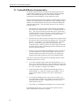
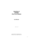
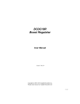
SC105 9-Pin to RS-232-DCE
Interface
User Guide
Issued 19.10.10
Copyright © 2004-2010 Campbell Scientific Inc.
Copied under licence by Campbell Scientific Ltd.
CSL 36
Guarantee
This equipment is guaranteed against defects in materials and workmanship.
This guarantee applies for twelve months from date of delivery. We will
repair or replace products which prove to be defective during the guarantee
period provided they are returned to us prepaid. The guarantee will not apply
to:
•
Equipment which has been modified or altered in any way without the
written permission of Campbell Scientific
•
Batteries
•
Any product which has been subjected to misuse, neglect, acts of God or
damage in transit.
Campbell Scientific will return guaranteed equipment by surface carrier
prepaid. Campbell Scientific will not reimburse the claimant for costs incurred
in removing and/or reinstalling equipment. This guarantee and the Company’s
obligation thereunder is in lieu of all other guarantees, expressed or implied,
including those of suitability and fitness for a particular purpose. Campbell
Scientific is not liable for consequential damage.
Please inform us before returning equipment and obtain a Repair Reference
Number whether the repair is under guarantee or not. Please state the faults as
clearly as possible, and if the product is out of the guarantee period it should
be accompanied by a purchase order. Quotations for repairs can be given on
request. It is the policy of Campbell Scientific to protect the health of its
employees and provide a safe working environment, in support of this policy a
“Declaration of Hazardous Material and Decontamination” form will be
issued for completion.
When returning equipment, the Repair Reference Number must be clearly
marked on the outside of the package. Complete the “Declaration of
Hazardous Material and Decontamination” form and ensure a completed copy
is returned with your goods. Please note your Repair may not be processed if
you do not include a copy of this form and Campbell Scientific Ltd reserves
the right to return goods at the customers’ expense.
Note that goods sent air freight are subject to Customs clearance fees which
Campbell Scientific will charge to customers. In many cases, these charges are
greater than the cost of the repair.
Campbell Scientific Ltd,
Campbell Park, 80 Hathern Road,
Shepshed, Loughborough, LE12 9GX, UK
Tel: +44 (0) 1509 601141
Fax: +44 (0) 1509 601091
Email: [email protected]
www.campbellsci.co.uk
PLEASE READ FIRST
About this manual
Please note that this manual was originally produced by Campbell Scientific Inc. primarily for the
North American market. Some spellings, weights and measures may reflect this origin.
Some useful conversion factors:
Area: 1 in2 (square inch) = 645 mm2
Length:
1 in. (inch) = 25.4 mm
1 ft (foot) = 304.8 mm
1 yard = 0.914 m
1 mile = 1.609 km
Mass:
1 oz. (ounce) = 28.35 g
1 lb (pound weight) = 0.454 kg
Pressure:
1 psi (lb/in2) = 68.95 mb
Volume:
1 UK pint = 568.3 ml
1 UK gallon = 4.546 litres
1 US gallon = 3.785 litres
In addition, while most of the information in the manual is correct for all countries, certain information
is specific to the North American market and so may not be applicable to European users.
Differences include the U.S standard external power supply details where some information (for
example the AC transformer input voltage) will not be applicable for British/European use. Please
note, however, that when a power supply adapter is ordered it will be suitable for use in your country.
Reference to some radio transmitters, digital cell phones and aerials may also not be applicable
according to your locality.
Some brackets, shields and enclosure options, including wiring, are not sold as standard items in the
European market; in some cases alternatives are offered. Details of the alternatives will be covered in
separate manuals.
Part numbers prefixed with a “#” symbol are special order parts for use with non-EU variants or for
special installations. Please quote the full part number with the # when ordering.
Recycling information
At the end of this product’s life it should not be put in commercial or domestic refuse
but sent for recycling. Any batteries contained within the product or used during the
products life should be removed from the product and also be sent to an appropriate
recycling facility.
Campbell Scientific Ltd can advise on the recycling of the equipment and in some cases
arrange collection and the correct disposal of it, although charges may apply for some
items or territories.
For further advice or support, please contact Campbell Scientific Ltd, or your local agent.
Campbell Scientific Ltd, Campbell Park, 80 Hathern Road, Shepshed, Loughborough, LE12 9GX, UK
Tel: +44 (0) 1509 601141 Fax: +44 (0) 1509 601091
Email: [email protected]
www.campbellsci.co.uk
Contents
PDF viewers note: These page numbers refer to the printed version of this document. Use
the Adobe Acrobat® bookmarks tab for links to specific sections.
1. General Description .................................................... 1
2. Specifications .............................................................. 2
3. Set-up Menu ................................................................. 3
3.1 Set-up Menu Selections ............................................................................ 4
4. Installation.................................................................... 5
5. RAD Modem Application ............................................. 5
5.1 RAD Modem - Two Way ......................................................................... 6
5.2 RAD Modem Wiring and Grounding ....................................................... 6
5.3 Testing RAD Modem Communication ..................................................... 8
6. CDMA Modem Application .......................................... 9
7. Freewave Radio Application ....................................... 9
Figures
1.
2.
3.
4.
SC105 9-Pin to RS-232-DCE Interface ...................................................... 1
Set-up Menu ............................................................................................... 4
Two Way Communication .......................................................................... 6
Installation of Spark Gap Protection........................................................... 7
Table
1. Approximate Range, miles and km............................................................. 6
i
SC105 9-Pin to RS-232-DCE Interface
Figure 1. SC105 9-Pin to RS-232-DCE Interface
1. General Description
The SC105 (Figure 1) is used to interface a CSI datalogger to any modem that is
configured with an RS-232 DCE (Data Communications Equipment) serial port.
The SC105 is an intelligent interface that buffers data (1k buffer size), allowing
many RS-232 data rates, and all CS I/O port modes.
Features include:
•
True RS-232 signal levels.
•
Power for the SC105 is supplied from the 5 V supply on pin 1 of the
datalogger’s I/O port. The SC105 will use the 5 V supply to power the
RS-232 modem if needed.
•
Two way (interactive) communication.
•
Supports most RS-232 baud rates.
•
Supports all CS I/O port modes.
The SC105 is frequently used with a short haul modem to communicate across a
dedicated line made of two pairs of twisted wire with a shield. Section 3
describes the details of this application using a short haul modem built by RAD.
The SC105 is also commonly used with satellite transmitters, cellular modems,
and spread spectrum radios.
The SC105 also supports one way output or printer communication.
1
SC105 9-Pin to RS-232-DCE Interface
2. Specifications
RS-232 9-Pin Female Connector Pin-out:
Pin No.
1
2
3
4
5
6
7
8
9
I/O
In
In
Out
Out
In
Out
In
In
Name
DCD
RXD
TXD
DTR
GND
DSR
RTS
CTS
Ring
Description
Data Carrier Detect (No Connection)
Received Data
Transmitted Data
Data Terminal Ready
Signal Ground
Data Set Ready (No Connection)
Request to Send – Modem Enable
Clear to Send
Rings Datalogger
CS I/O 9-Pin Male Connector Pin-out:
2
Pin No. I/O
Name
Description
1
2
3
4
5
6
7
8
9
+5V
GND
RING
RXD
ME
SDE
CLK/HS
+12V
TXD
Regulated 5 Volt supply
Ground
Ring signal to datalogger
SC105 transmits on this line
Modem Enable—must be high for transfer in ME mode
Synchronous Device Enable
Clock/Handshake (for synchronous communication)
Not Used
SC105 receives on this line
in
out
out
in
in
In
in
User Guide
RS-232 Baud Rates
The SC105 will support the following baud rates:
1200, 9600, 19200, 38400, 57600, 115200
RS-232 Parity and Data
The SC105 supports the following:
Parity:
Even, Odd, None
Data Bits:
7, 8
CS I/O Port Modes:
CSDC, SDC, ME, Addressed Print Device for P96 output
Electrical
The SC105 uses power from the +5 V line on the 9-pin interface connected to
the datalogger.
Current
Standby:
0.16 mA
Communicating: 1 to 4 mA
Additional current (up to 8 mA) from the 5 V supply may be used by the
RS-232 device connected to the SC105.
Physical
Height:
Width:
Length:
Weight:
0.9 in (2.3 cm)
1.6 in (4.1 cm)
3.5 in (8.9 cm)
1.6 oz (45.4 g)
Environmental
Temperature:
Humidity:
-25o to +50oC
up to 95% non-condensing
3. Set-up Menu
The SC105 has a built-in Set-up Menu for configuring communication mode, CS
I/O port configuration, RS-232 port configuration, and other parameters. The
Set-up Menu is shown in Figure 2. It is accessed by connecting the SC105’s
RS-232 port to a PC with the included null modem cable. The SC105 also needs
to have power. Usually the SC105 is powered by connecting the SC105’s CS
I/O port to the CS I/O port of a datalogger.
With the null modem connection to the PC, typically Campbell Scientific’s
Device Configuration (DevConfig) Utility is used, but a terminal program such
as HyperTerminalTM or ProcommTM (always 9600 baud, 8-N-1) can also be
used. Press the “Program” button on the SC105 for one second to access the
Set-up Menu. Changed settings are saved in flash memory by selecting Apply in
DevConfig or menu item “4” if using HyperTerminal or Procomm. If left idle,
the Set-up Menu will time out 60 seconds after the last received character and
exit without saving any parameter changes with the message “Set-up Timeout.”
A datalogger can remain connected to the CS I/O port (to provide power to
3
SC105 9-Pin to RS-232-DCE Interface
SC105) while setting SC105 parameters on the RS-232 port, although CS I/O
communications would be inactive until exiting the Set-up Menu.
SC105 - SW Version 2.0
Main Menu:
Current Configuration
(1) CS I/O Port Configuration [Modem Enable]
(2) RS-232 Port Configuration [9600]
(3) Restore Factory Defaults
(4) Save and Exit
(5) Exit w/o Saving Settings
(9) Help
Enter Choice:
Figure 2. Set-up Menu
3.1 Set-up Menu Selections
1)
CS I/O Port Configuration
An SC105 may be activated either by the Modem Enable signal or by a
Synchronous Device (SDC) address (7, 8, or 9).
If PakBus Networking is being used, SDC address 7 or 8 should be
selected.
Addressed Print Device is a mode that allows output from the datalogger
when it executes the P96 instruction.
2)
RS-232 Port Configuration
RS-232 baud rate, data bits, and parity are configured here, as well as the
RS-232 Auto Power Down (APD) Mode. The APD mode should be left
enabled, unless the attached RS-232 device requires power from the
RS-232 lines.
The DTR and RTS Mode setting allows control over how these two lines
behave.
DTR is on pin 4 of the RS-232 connector; RTS is on pin 7.
4
User Guide
'PC/PDA mode': DTR and RTS are both driven to 5 V.
'Modem mode': DTR will be driven to +5 V when the CS I/O interface is
active for Modem Enable, SDC Address 9, and
Addressed Print Device configurations. When the
CS I/O is inactive, DTR will be 0 V.
Additionally, there will be a 'dead time' after DTR is
dropped of 2 sec when data coming in on the RS-232 will
be ignored.
For SDC Address 7 or 8, DTR will always be driven to
+5 V.
RTS will 'key' the data; it will be driven (+5 V) 20 msec
prior to data being sent out the RS-232, and remain
driven for 5 seconds after the last data is sent out the RS232.
'Custom mode': This mode is identical to the 'Modem mode', except the
delays between RTS HI and data, data and RTS LO, and
the 'dead time' are all configurable.
4. Installation
Connect the SC105 to the RS-232 device and to the datalogger with the SC12 9pin cable (included). If the device has a 25-pin connector, a 9-pin female to 25pin male adapter is required (CSI PN #15751).
Proper transient protection should be installed to protect the computer and
datalogger in areas where damage due to lightning is possible. If this is a RAD
modem application, see Section 5.2.
5. RAD Modem Application
The SC105 is frequently used with a short-range modem to communicate across
a 4-wire, unconditioned dedicated line. Campbell Scientific offers a kit
(PN TBD) that includes the SC105, the 9- to 25-pin adapter (PN #15751), and a
mounting bracket (PN #6282). The bracket will mount the RAD, SC105, and
adapter to the back plate in a Campbell Scientific enclosure. This section
describes using a short-range asynchronous modem built by RAD*.
* SRM - 5A RAD Modem
RAD Data Communications, Inc.
900 Corporate Drive
Mahwah, NJ 07430
Tel: (201) 529-1100
Fax: (201) 529-5777
Email: [email protected]
http://www.rad.com
5
SC105 9-Pin to RS-232-DCE Interface
For transmission, the RAD modem uses a cable made of two pairs of twisted
wires with a shield. Data rates up to 9600 bps are possible. The low voltage
transmission levels minimize cross talk between adjacent lines within the same
cable. Data are transmitted and received at a balanced impedance, providing
excellent immunity to circuit noise. Table 1 gives the data rate possible for
several gage cables across several distances.
Table 1. Approximate Range, miles and km
Data
Rate
Bps
19 Gauge (0.9 mm)
24 Gauge (0.5 mm)
26 Gauge (0.4 mm)
miles
km
Miles
km
miles
km
9,600
1,200
6.2
7.6
10.0
12.2
2.8
3.4
4.5
5.5
2.0
2.5
3.3
4.0
5.1 RAD Modem - Two Way
PC
SRM
4-WIRE UNCONDITIONED
TELEPHONE LINE
OR
TWO TWISTED PAIRS
SRM
9 TO 25 PIN
ADAPTOR
SC105
DATALOGGER
Figure 3. Two Way Communication
When using Campbell Scientific’s datalogger support software to communicate
through the SC105/RAD modem, “Set-up” the link as a direct connect between
the datalogger and the desired COM port. Start two way communication using
the “Connect” button on the tool bar and the “Connect” button in the “Connect”
window.
5.2 RAD Modem Wiring and Grounding
Figure 4 shows a typical set-up of the RAD modems. Installation is as follows:
1.
Set the DCE/DTE switch on the back of the RAD modem connected to the
SC105 to DCE. For a RAD modem connected to a PC, set the DCE/DTE
switch to DCE. For a RAD modem connected to a serial printer, set the
DCE/DTE switch to DTE.
2.
Select a cable with two or more twisted pairs. A recommended direct
burial rodent resistant cable is listed below. They also sell several gopher
resistant cables for even greater protection.
Company
Part Number
Anixter
F-02P22BPN
Tel: 847-677-2600
http://www.anixter.com
6
AWG.
22
3.
Wiring connections are made as shown in Figure 4. Note wires labelled A
and B are one twisted pair of the cable. Wires labelled C and D are the
other twisted pair.
4.
Transients induced on the communication line may damage any electronics
connected at either end of the line. To decrease the chances for damage,
spark gaps should be installed as shown in Figure 4. The transient
protection shown may be purchased from Campbell Scientific, Inc. (p.n.
#5563 shown in Figure 4, p.n. #6536 includes a plastic case, p.n. #6361
User Guide
includes hardware for mounting to ground lug of CSI enclosures models
ENC 10/12, ENC 12/14, or ENC 16/18). Spark gap wiring is straight
through such that pin to pin continuity exists between the two modems. If
the modems are installed entirely within a building, the transient spark gap
protection is probably not needed.
Figure 4. Installation of Spark Gap Protection
Occasionally a customer needs to transmit data across longer or smaller gage
wires or at higher speeds than can be done with the RAD modem powered by
the SC105. RAD does sell a 9-volt power supply that will boost the signals
enough to meet some of these more demanding applications. Please contact
RAD for more information.
7
SC105 9-Pin to RS-232-DCE Interface
5.3 Testing RAD Modem Communication
The modem communication link is divided into the following three sections:
1) RAD modem computer end, 2) cable from computer modem to datalogger
modem, 3) RAD modem datalogger end. When unable to establish
communication with the datalogger, test each of the three sections.
Before proceeding through the testing procedures, a terminal emulator software
program such as HyperTerminalTM or Campbell Scientific’s datalogger support
software (Test Terminal Emulator) must be used to communicate through the
COM port of the computer. Once the emulator program is set up, testing can
proceed as follows:
1.
Disconnect the four conductor cables from the SRM-6A RAD modem at
the computer end. Jumper the XMT + to RCV + and jumper the XMT - to
RCV -. This creates a transmit loop which allows any key pressed at the
computer keyboard to be seen on the screen. If the key pressed is not seen,
check the following: COM port configuration, 25-pin cable from the
computer to the modem and the RAD modem.
2.
Reconnect the four conductor cables to the modem at the computer end and
disconnect the cable from the modem at the datalogger end. Twist together
the XMT + wire and RCV + wire, twist together the XMT - wire and the
RCV - wire. Repeat the process of step 1 by pressing a key on the
computer keyboard. If the key pressed is not returned, then the cable from
the modem at the computer to the datalogger modem is defective and will
need to be repaired or replaced.
3.
If steps 1 and 2 pass, the modem at the datalogger is suspect. Disconnect
the modem from the SC105 and bring the modem to the computer site.
Attach the modem to the computer, and repeat step 1 by jumpering the
terminals of the modem and pressing a key on the computer keyboard.
If the above tests pass and communication to the datalogger still has not been
established, perform tests 4, 5, and 6.
4.
A 12 V lead acid battery supply should not be discharged below 11.76 V.
If this occurs, the batteries will go into a deep discharge state and will need
to be replaced. The CR10 will function properly on a battery voltage of 10
to 15 volts. Check the 12 V supply with a voltmeter.
5.
On the wiring panel of most Campbell Scientific dataloggers there is a
terminal marked 5 V. Check the 5 V supply with a voltmeter. This 5 V
supply should be within a tenth of a volt. If not, it would indicate a
problem.
6.
To verify that the datalogger and its serial I/O port are working, try to
access input memory locations using a laptop PC with the SC105 (using a
null modem cable connection). Configure the SC105 CS I/O Port to
Modem Enable for this test.
7.
If test 6 fails, use a CR10KD Keyboard Display to access input locations.
If the datalogger passes tests 4, 5, and 7, but fails test 6, then the SC105 is
suspect and will need to be repaired or replaced.
8
User Guide
6. CDMA Modem Application
In most modem applications the SC105 can be used with the factory defaults.
This sets the SC105 up as modem enable 9600 baud, 8 data bits, Parity None
and 1 stop bit. It also sets the DTR dead time to 2 seconds. This dead time is
used to prevent characters produce by the modem from waking the datalogger up
right after communications has been terminated. The dead time can be adjusted
by changing the RS-232 DTR and RTS mode to Custom.
The CS I/O port configuration has several other modes that can be used
depending on the operating system used in the datalogger. These other modes
offer advantages for some applications. When using the PakBus OS, SDC7 or
SDC8 can be used. This allows communications from multiple sources at the
same time (for example, CDMA modem, RF400, and CR10KD).
Valid modes by Operating System:
Modem
Enable
Standard OS (Array)
X
Table Data OS
X
PakBus OS
X
SDC 7, SDC 8
SDC 9
X
X
7. Freewave Radio Application
Typically, the Freewave Radios will be used in a PakBus network, with PakBus
OS dataloggers.
With a PakBus datalogger, the CS I/O port configuration on the SC105 should
be set to SDC 7 or SDC 8. The RS-232 baud rate should be set to match the
baud rate on the Freewave radios (38.4 k or 115 k are good choices).
If the low power modes of the Freewave radios are to be used, the SC105 DTR
and RTS mode setting will need to be configured to compensate for the turn-on
latency of the Freewave radio. The radio uses the RTS signal to go in and out of
its low power mode. The radio requires a delay from the time that it is brought
out of the low power mode and the time it receives data over the
RS-232 port.
To do this, the default DTR and RTS mode will have to be changed to Custom
with RTS High = 100, and RTS Low = 20. This gives 100 msec between RTS
HI and data on the RS-232 port, and 2 seconds between data on the RS-232 port
and RTS going LO.
For a detailed Application Note on using Freewave Radios, see PakBus
Networking with Freewave Radios. This application note gives complete details
on the set-up of the datalogger, the SC105, the Freewave radio, and LoggerNet
PC software for this application.
9
CAMPBELL SCIENTIFIC COMPANIES
Campbell Scientific, Inc. (CSI)
815 West 1800 North
Logan, Utah 84321
UNITED STATES
www.campbellsci.com • [email protected]
Campbell Scientific Africa Pty. Ltd. (CSAf)
PO Box 2450
Somerset West 7129
SOUTH AFRICA
www.csafrica.co.za • [email protected]
Campbell Scientific Australia Pty. Ltd. (CSA)
PO Box 444
Thuringowa Central
QLD 4812 AUSTRALIA
www.campbellsci.com.au • [email protected]
Campbell Scientific do Brazil Ltda. (CSB)
Rua Luisa Crapsi Orsi, 15 Butantã
CEP: 005543-000 São Paulo SP BRAZIL
www.campbellsci.com.br • [email protected]
Campbell Scientific Canada Corp. (CSC)
11564 - 149th Street NW
Edmonton, Alberta T5M 1W7
CANADA
www.campbellsci.ca • [email protected]
Campbell Scientific Centro Caribe S.A. (CSCC)
300N Cementerio, Edificio Breller
Santo Domingo, Heredia 40305
COSTA RICA
www.campbellsci.cc • [email protected]
Campbell Scientific Ltd. (CSL)
Campbell Park
80 Hathern Road
Shepshed, Loughborough LE12 9GX
UNITED KINGDOM
www.campbellsci.co.uk • [email protected]
Campbell Scientific Ltd. (France)
Miniparc du Verger - Bat. H
1, rue de Terre Neuve - Les Ulis
91967 COURTABOEUF CEDEX
FRANCE
www.campbellsci.fr • [email protected]
Campbell Scientific Spain, S. L.
Avda. Pompeu Fabra 7-9
Local 1 - 08024 BARCELONA
SPAIN
www.campbellsci.es • [email protected]
Campbell Scientific Ltd. (Germany)
Fahrenheitstrasse13, D-28359 Bremen
GERMANY
www.campbellsci.de • [email protected]
Please visit www.campbellsci.com to obtain contact information for your local US or International representative.