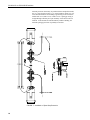
1
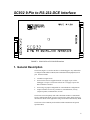
INSTRUCTION MANUAL
SC932 9-Pin to
RS-232-DCE Interface
Revision: 4/03
C o p y r i g h t ( c ) 1 9 8 7 - 2 0 0 3
C a m p b e l l S c i e n t i f i c , I n c .
Warranty and Assistance
The SC932 9 PIN TO RS-232-DCE INTERFACE is warranted by
CAMPBELL SCIENTIFIC, INC. to be free from defects in materials and
workmanship under normal use and service for twelve (12) months from date of
shipment unless specified otherwise. Batteries have no warranty. CAMPBELL
SCIENTIFIC, INC.'s obligation under this warranty is limited to repairing or
replacing (at CAMPBELL SCIENTIFIC, INC.'s option) defective products.
The customer shall assume all costs of removing, reinstalling, and shipping
defective products to CAMPBELL SCIENTIFIC, INC. CAMPBELL
SCIENTIFIC, INC. will return such products by surface carrier prepaid. This
warranty shall not apply to any CAMPBELL SCIENTIFIC, INC. products
which have been subjected to modification, misuse, neglect, accidents of
nature, or shipping damage. This warranty is in lieu of all other warranties,
expressed or implied, including warranties of merchantability or fitness for a
particular purpose. CAMPBELL SCIENTIFIC, INC. is not liable for special,
indirect, incidental, or consequential damages.
Products may not be returned without prior authorization. The following
contact information is for US and International customers residing in countries
served by Campbell Scientific, Inc. directly. Affiliate companies handle repairs
for customers within their territories. Please visit www.campbellsci.com to
determine which Campbell Scientific company serves your country. To obtain
a Returned Materials Authorization (RMA), contact CAMPBELL
SCIENTIFIC, INC., phone (435) 753-2342. After an applications engineer
determines the nature of the problem, an RMA number will be issued. Please
write this number clearly on the outside of the shipping container.
CAMPBELL SCIENTIFIC's shipping address is:
CAMPBELL SCIENTIFIC, INC.
RMA#_____
815 West 1800 North
Logan, Utah 84321-1784
CAMPBELL SCIENTIFIC, INC. does not accept collect calls.
SC932 Table of Contents
PDF viewers note: These page numbers refer to the printed version of this document. Use
the Adobe Acrobat® bookmarks tab for links to specific sections.
1. General Description....................................................1
2. Specifications .............................................................2
3. Installation...................................................................3
3.1
3.2
3.3
3.4
Two Way Communication ........................................................................3
One Way Communication.........................................................................4
Two Way or One Way Communication....................................................4
Jumper Descriptions..................................................................................6
4. RAD Modem Application ............................................7
4.1
4.2
4.3
4.4
4.5
RAD Modem - Two Way..........................................................................7
RAD Modem - One Way ..........................................................................8
RAD Modem - Two Way or One Way .....................................................9
RAD Modem Wiring and Grounding........................................................9
Testing RAD Modem Communication ...................................................11
1.
2.
3.
4.
5.
6.
7.
SC932 9-Pin to RS-232-DCE Interface ......................................................1
SC932 Jumper Locations ............................................................................5
SC932 Jumper Descriptions........................................................................5
Two Way Communication ..........................................................................7
One Way Communication...........................................................................8
Two Way or One Way Communication......................................................9
Installation of Spark Gap Protection.........................................................10
Figures
Table
1. Approximate Range, miles and km .............................................................7
i
This is a blank page.
SC932 9-Pin to RS-232-DCE Interface
FIGURE 1. SC932 9-Pin to RS-232-DCE Interface
1. General Description
The SC932 (Figure 1) is used to interface a CSI datalogger to any modem that
is configured with an RS-232 DCE (Data Communications Equipment) serial
port. Features include:
•
True RS-232 signal levels.
•
Power for the SC932 is supplied from the 5 V supply on pin 1 of the
datalogger’s I/O port. The SC932 will use the 5 V supply to power the
RS-232 modem if needed.
•
Power usage is jumper configurable for certain hardware configurations.
•
Jumper selectable for two way (interactive) communication, one way
(output or printer) communication, or both.
The SC932 is most frequently used with a short haul modem to communicate
across a dedicated line made of 2 pairs of twisted wire with a shield. Section 3
describes the details of this application using a short haul modem built by RAD.
The SC932 is also commonly used with the satellite transmitters and spread
spectrum radios.
1
SC932 9-Pin to RS-232-DCE Interface
2. Specifications
25 Pin Male Connector Pin-out:
Pin No.
I/O
1
2
3
4
7
20
22
out
in
out
out
in
Name
Description
GND
TXD
RXD
RTS
GND
DTR
RING
Chassis Ground
SC932 transmits data on this line
SC932 receives data on this line
Held active by SC932 (see jumper description
Signal Ground
Held active by SC932 (see jumper description
Rings datalogger
9 Pin Male Connector Pin-out:
Pin No. I/O
Name
Description
1
2
3
4
5
6
9
+5V
GND
RING
RXD
ME
SDE
TXD
Regulated 5 Volt supply
Ground
Ring signal to datalogger
SC932 transmits on this line
Modem Enable
Synchronous Device Enable
SC932 receives on this line
in
out
out
in
in
in
Data Rates
The SC932 will support baud rates up to 19,200 bps
2
SC932 9-Pin to RS-232-DCE Interface
Electrical
The SC932 uses power from the +5 V line on the 9 pin interface connected to
the datalogger. The SC932 uses only a few microamps while inactive and
about 5 mA when active from the 5 V supply. Additional current (up to 10
mA) from the 5 V supply may be used by the RS-232 device connected to the
SC932.
Physical
Height:
Width:
Length:
Weight:
Mounting:
1.0 in (25 mm)
3.5 in (90 mm)
4.1 in (103 mm)
4.3 oz (123 g)
3 in by 3 in centered holes
Environmental
Temperature: -25 to +50oC
Humidity:
up to 95% non-condensing
3. Installation
Proper transient protection should be installed to protect the computer and
datalogger in areas where damage due to lightning is possible. If this is a RAD
modem application, see Section 4.
3.1 Two Way Communication:
1.
Remove the SC932 lid by removing the screw from the top of the box.
2.
Jumper P3 between pins 1-2 (activated by Modem Enable) to set the
SC932 for two way communication. See Figures 2 and 3.
3.
Select the jumper configuration of P2 and P4 that will minimize power
requirements and yet still allow the SC932 to function. There are three
valid configurations of these jumpers. Having both P2 and P4 open will
require the least power. Jumpering P4 only is the middle power level.
Jumpering P2 only requires the most power. Modem devices which draw
power from the SC932 interface usually require one of the higher power
levels. If the RAD modem is being used, Section 4 describes the jumper
settings to use.
4.
Replace the lid.
5.
Connect the SC932 to the RS-232 device and to the datalogger with the
SC12 9 pin cable (included).
3
SC932 9-Pin to RS-232-DCE Interface
3.2 One Way Communication
1.
Remove the SC932 lid by removing the screw from the top of the box.
2.
Jumper P3 between pins 3-4 to set the SC932 to one way data only. The
SC932 is activated by pin 6 synchronous device enable (SDE) on the
datalogger’s serial I/O port. See Figures 2 and 3.
3.
Select the jumper configuration of P2 and P4 that will minimize power
requirements and yet still allow the SC932 to function. There are three
valid configurations of these jumpers. Having both P2 and P4 open will
require the least power. Jumpering P4 only is the middle power level.
Jumpering P2 only requires the most power. Modem devices which draw
power from the SC932 interface usually require one of the higher power
levels. If the RAD modem is being used, Section 4 describes the jumper
settings to use.
4.
Replace the lid.
5.
Connect the SC932 to the RS-232 device and to the datalogger with the
SC12 9 pin cable (included).
3.3 Two Way or One Way Communication
4
1.
Remove the SC932 lid by removing the screw from the top of the box.
2.
Jumper P3 between pins 1-2 and between pins 3-4 to set the SC932 for
two way or one way telecommunications. See Figures 2 and 3.
3.
Select the jumper configuration of P2 and P4 that will minimize power
requirements and yet still allow the SC932 to function. There are three
valid configurations of these jumpers. Having both P2 and P4 open will
require the least power. Jumpering P4 only is the middle power level.
Jumpering P2 only requires the most power. Modem devices which draw
power from the SC932 interface usually require one of the higher power
levels. If the RAD modem is being used, Section 4 describes the jumper
settings to use.
4.
Replace the lid.
5.
Connect the SC932 to the RS-232 device and to the datalogger with the
SC12 9 pin cable (included).
SC932 9-Pin to RS-232-DCE Interface
P2
P3
P4
FIGURE 2. SC932 Jumper Locations
FIGURE 3. SC932 Jumper Descriptions
5
SC932 9-Pin to RS-232-DCE Interface
3.4 Jumper Descriptions
The following guidelines are used to determine the proper jumper configuration
for the modem being used. When selecting a jumper configuration always try
to keep current drain to a minimum.
Current
Drain
LO
MEDIUM
HIGH
6
Jumper
Position
Description
P3
1-2
Allows SC932 to act as a Datalogger
Modem device (two way communication).
SC932 is activated by modem enable
(ME) line.
3-4
Allows SC932 to act as a Datalogger
Printer device (one way). SC932 is
activated by pin 6 synchronous device
enable (SDE) on the datalogger’s Serial
I/O port.
1-2 3-4
Allows SC932 to act as both of the above.
The one way data mode resumes once the
modem enable (ME) is dropped. The ME
line is dropped when the two way
communication is shut down or after 40
seconds of inactivity.
P2
Open
P4
Open
P2
Open
P4
Installed
P2
Installed
P4
Open
DTR and RTS are held at 9V while the
SC932 is active. They are not driven
while the SC932 is not active. This
jumper selection should be used when the
SC932 is being used for Printer data or
when the RS-232 device connected to the
SC932 can produce a ring or RXD signal
while DTR, RTS, and TXD are not
powered (e.g. Hayes Modem).
DTR and RTS are held at 4.3V while the
SC932 is not active and 9V while active.
This jumper selection should be used
when the RS-232 device connected to the
SC932 can produce a ring or RXD signal
when DTR and RTS are at 4.3V and TXD
is not driven. This configuration will take
more power than when both P2 and P4 are
open depending on the RS-232 device
(e.g. RAD modems).
DTR and RTS are held at 9V all the time.
This configuration takes the most power,
and provides fully active RS-232 signals
on the DTR, RTS, and TXD lines all the
time. Any RS-232 compatible device
should work with this jumper selection.
SC932 9-Pin to RS-232-DCE Interface
4. RAD Modem Application
The SC932 is most frequently used with a short range modem to communicate
across a 4-wire, unconditioned dedicated line. This section describes the
details of this application using a short range asynchronous modem built by
RAD*.
* SRM - 5A RAD Modem
RAD Data Communications Inc.
900 Corporate Drive
Mahwah, NJ 07430
Tel: (201) 529-1100
Fax: (201) 529-5777
Email: [email protected]
http://www.rad.com
For transmission, the RAD modem uses a cable made of 2 pairs of twisted
wires with a shield. Data rates up to 9600 bps are possible. The low voltage
transmission levels minimize cross-talk between adjacent lines within the same
cable. Data are transmitted and received at a balanced impedance, providing
excellent immunity to circuit noise. Table 1 gives the data rate possible for
several gage cables across several distances.
TABLE 1. Approximate Range, miles and km
Data Rate
bps
19 Gauge (0.9 mm)
miles
km
24 Gauge (0.5 mm)
miles
km
26 Gauge (0.4 mm)
miles
km
9,600
1,200
6.2
7.6
2.8
3.4
2.0
2.5
10.0
12.2
4.5
5.5
3.3
4.0
Figures 4, 5, and 6 show specific jumper settings for three applications with the
RAD Modem. Figure 4 is an example of two way communication with a
computer, Figure 5 shows one way communication to a printer or display, and
Figure 6 shows both. Note the differences in jumper settings.
4.1 RAD Modem - Two Way
FIGURE 4. Two Way Communication
7
SC932 9-Pin to RS-232-DCE Interface
The SC932 leaves the factory with the jumpers set as shown in Figure 4. In this
mode, the SC932 and RAD modem combined will require about 2 mA while
inactive and less than 20 mA while active. When using Campbell Scientific’s
PC208W telecommunications software to communicate through the
SC932/RAD modem, “Setup” the link as a direct connect between the
datalogger and the desired COM port. Start two way communication using the
“Connect” button on the Tool bar and the “Connect” button in the “Connect”
window.
4.2 RAD Modem - One Way
FIGURE 5. One Way Communication
In this mode, the SC932 and RAD modem combined will require about 2 mA
while inactive and less than 20 mA while active.
Use Instruction 96 in the datalogger to output data to a printer or display. The
bit rate, parity, start and stop bits must be the same in the datalogger and the
display/printer. The datalogger sends the data as 8 data bits, no parity, 1 start
bit and 1 stop bit. When using Campbell Scientific’s PC208W
telecommunications software to display “printer” data sent by the datalogger
“Setup” the link as a direct connect between the datalogger and the desired
COM port. Start one way communication using the “Connect” button on the
Tool bar, the “Terminal” tab, and the “Open Port” button in the “Terminal” tab.
Wait for the data to be displayed.
NOTE
8
Only one twisted pair is required for one way communication.
Refer to RAD manual for wire connections.
SC932 9-Pin to RS-232-DCE Interface
4.3 RAD Modem - Two Way or One Way
FIGURE 6. Two Way or One Way Communication
In the jumper configuration shown in Figure 6, the communication mode, two
way or one way is determined by the modem enable line. Communication is
two way if the modem enable line is high, one way if modem enable is low. In
this mode, the SC932 and RAD modem combined will require about 2 mA
while inactive and less than 20 mA while active.
Two way setup and connect: same as two way only. One way setup and
connect: same as one way only.
4.4 RAD Modem Wiring and Grounding
Figure 7 shows a typical setup of the RAD modems. Installation is as follows:
1.
Set the DCE/DTE switch on the back of the RAD modem connected to the
SC932 to DCE. For a RAD modem connected to a PC, set the DCE/DTE
switch to DCE. For a RAD modem connected to a serial printer, set the
DCE/DTE switch to DTE.
2.
Select a cable with two or more twisted pairs. A recommended direct
burial rodent resistant cable is listed below. They also sell several gopher
resistant cables for even greater protection.
Company
Part Number
Anixter
F-02P22BPN
Tel: 847-677-2600
http://www.anixter.com
AWG.
22
3.
Wiring connections are made as shown in Figure 7. Note wires labeled A
and B are one twisted pair of the cable. Wires labeled C and D are the
other twisted pair.
4.
Transients induced on the communication line may damage any
electronics connected at either end of the line. To decrease the chances
for damage, spark gaps should be installed as shown in Figure 7. The
9
SC932 9-Pin to RS-232-DCE Interface
transient protection shown may be purchased from Campbell Scientific,
Inc. (p.n. 5563 shown in Figure 7, p.n. 6536 includes a plastic case, p.n.
6361 includes hardware for mounting to ground lug of CSI enclosures
models ENC 10/12, ENC 12/14, or ENC 16/18). Spark gap wiring is
straight through such that pin to pin continuity exists between the two
modems. If the modems are installed entirely within a building, the
transient spark gap protection is probably not needed.
FIGURE 7. Installation of Spark Gap Protection
10
SC932 9-Pin to RS-232-DCE Interface
Occasionally a customer needs to transmit data across longer or smaller gage
wires or at higher speeds than can be done with the RAD modem powered by
the SC932. RAD does sell a 9 volt power supply that will boost the signals
enough to meet some of these more demanding applications. Please contact
RAD for more information.
4.5 Testing RAD Modem Communication
The modem communication link is divided into the following three sections: 1)
RAD modem computer end, 2) cable from computer modem to datalogger
modem, 3) RAD modem datalogger end. When unable to establish
communication with the datalogger, test each of the three sections.
Before proceeding through the testing procedures, a terminal emulator software
program such as “KERMIT”, “PROCOMM”, or Campbell Scientific’s
PC208W (Remote Keyboard Display Terminal) must be used to communicate
through the COM port of the computer. Once the emulator program is set up,
testing can proceed as follows:
1.
Disconnect the 4 conductor cables from the SRM-6A RAD modem at the
computer end. Jumper the XMT + to RCV + and jumper the XMT - to
RCV -. This creates a transmit loop which allows any key pressed at the
computer keyboard to be seen on the screen. If the key pressed is not
seen, check the following: COM port configuration, 25 pin cable from the
computer to the modem and the RAD modem.
2.
Reconnect the 4 conductor cables to the modem at the computer end and
disconnect the cable from the modem at the datalogger end. Twist
together the XMT + wire and RCV + wire, twist together the XMT - wire
and the RCV - wire. Repeat the process of step 1 by pressing a key on the
computer keyboard. If the key pressed is not returned, then the cable from
the modem at the computer to the datalogger modem is defective and will
need to be repaired or replaced.
3.
If steps 1 and 2 pass, the modem at the datalogger is suspect. Disconnect
the modem from the SC932 and bring the modem to the computer site.
Attach the modem to the computer, and repeat step 1 by jumpering the
terminals of the modem and pressing a key on the computer keyboard.
If the above tests pass and communication to the datalogger still has not been
established, perform tests 4, 5, and 6.
4.
A 12 V lead acid battery supply should not be discharged below 11.76 V.
If this occurs, the batteries will go into a deep discharge state and will
need to be replaced. The CR10 will function properly on a battery voltage
of 10 to 15 volts. Check the 12 V supply with a volt meter.
5.
On the wiring panel of most Campbell Scientific dataloggers there is a
terminal marked 5 V. Check the 5 V supply with a volt meter. This 5 V
supply should be within a tenth of a volt. If not, it would indicate a
problem.
11
SC932 9-Pin to RS-232-DCE Interface
6.
To verify that the datalogger and its serial I/O port are working, try to
access input memory locations using a laptop PC with the SC32B or the
CR10KD Keyboard Display.
If the datalogger passes tests 4, 5, and 6, then the SC932 is suspect and will
need to be repaired or replaced.
12
This is a blank page.
Campbell Scientific Companies
Campbell Scientific, Inc. (CSI)
815 West 1800 North
Logan, Utah 84321
UNITED STATES
www.campbellsci.com
[email protected]
Campbell Scientific Africa Pty. Ltd. (CSAf)
PO Box 2450
Somerset West 7129
SOUTH AFRICA
www.csafrica.co.za
[email protected]
Campbell Scientific Australia Pty. Ltd. (CSA)
PO Box 444
Thuringowa Central
QLD 4812 AUSTRALIA
www.campbellsci.com.au
[email protected]
Campbell Scientific do Brazil Ltda. (CSB)
Rua Luisa Crapsi Orsi, 15 Butantã
CEP: 005543-000 São Paulo SP BRAZIL
www.campbellsci.com.br
[email protected]
Campbell Scientific Canada Corp. (CSC)
11564 - 149th Street NW
Edmonton, Alberta T5M 1W7
CANADA
www.campbellsci.ca
[email protected]
Campbell Scientific Ltd. (CSL)
Campbell Park
80 Hathern Road
Shepshed, Loughborough LE12 9GX
UNITED KINGDOM
www.campbellsci.co.uk
[email protected]
Campbell Scientific Ltd. (France)
Miniparc du Verger - Bat. H
1, rue de Terre Neuve - Les Ulis
91967 COURTABOEUF CEDEX
FRANCE
www.campbellsci.fr
[email protected]
Campbell Scientific Spain, S. L.
Psg. Font 14, local 8
08013 Barcelona
SPAIN
www.campbellsci.es
[email protected]
Please visit www.campbellsci.com to obtain contact information for your local US or International representative.