1
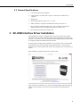
USER GUIDE SC-USB USB to CS I/O Opto-isolated Interface Issued: 17.12.13 Copyright © 2003-2013 Campbell Scientific Ltd. CSL 514 Guarantee This equipment is guaranteed against defects in materials and workmanship. This guarantee applies for twelve months from date of delivery. We will repair or replace products which prove to be defective during the guarantee period provided they are returned to us prepaid. The guarantee will not apply to: • Equipment which has been modified or altered in any way without the written permission of Campbell Scientific • Batteries • Any product which has been subjected to misuse, neglect, acts of God or damage in transit. Campbell Scientific will return guaranteed equipment by surface carrier prepaid. Campbell Scientific will not reimburse the claimant for costs incurred in removing and/or reinstalling equipment. This guarantee and the Company’s obligation thereunder is in lieu of all other guarantees, expressed or implied, including those of suitability and fitness for a particular purpose. Campbell Scientific is not liable for consequential damage. Please inform us before returning equipment and obtain a Repair Reference Number whether the repair is under guarantee or not. Please state the faults as clearly as possible, and if the product is out of the guarantee period it should be accompanied by a purchase order. Quotations for repairs can be given on request. It is the policy of Campbell Scientific to protect the health of its employees and provide a safe working environment, in support of this policy a “Declaration of Hazardous Material and Decontamination” form will be issued for completion. When returning equipment, the Repair Reference Number must be clearly marked on the outside of the package. Complete the “Declaration of Hazardous Material and Decontamination” form and ensure a completed copy is returned with your goods. Please note your Repair may not be processed if you do not include a copy of this form and Campbell Scientific Ltd reserves the right to return goods at the customers’ expense. Note that goods sent air freight are subject to Customs clearance fees which Campbell Scientific will charge to customers. In many cases, these charges are greater than the cost of the repair. Campbell Scientific Ltd, Campbell Park, 80 Hathern Road, Shepshed, Loughborough, LE12 9GX, UK Tel: +44 (0) 1509 601141 Fax: +44 (0) 1509 601091 Email: [email protected] www.campbellsci.co.uk PLEASE READ FIRST About this manual Some useful conversion factors: Area: 1 in2 (square inch) = 645 mm2 Length: 1 in. (inch) = 25.4 mm 1 ft (foot) = 304.8 mm 1 yard = 0.914 m 1 mile = 1.609 km Mass: 1 oz. (ounce) = 28.35 g 1 lb (pound weight) = 0.454 kg Pressure: 1 psi (lb/in2) = 68.95 mb Volume: 1 UK pint = 568.3 ml 1 UK gallon = 4.546 litres 1 US gallon = 3.785 litres Recycling information At the end of this product’s life it should not be put in commercial or domestic refuse but sent for recycling. Any batteries contained within the product or used during the products life should be removed from the product and also be sent to an appropriate recycling facility. Campbell Scientific Ltd can advise on the recycling of the equipment and in some cases arrange collection and the correct disposal of it, although charges may apply for some items or territories. For further advice or support, please contact Campbell Scientific Ltd, or your local agent. Campbell Scientific Ltd, Campbell Park, 80 Hathern Road, Shepshed, Loughborough, LE12 9GX, UK Tel: +44 (0) 1509 601141 Fax: +44 (0) 1509 601091 Email: [email protected] www.campbellsci.co.uk Contents 1. Introduction ................................................................ 1 2. Technical Specifications ............................................ 2 2.1 USB Specifications ................................................................................... 2 2.2 CS I/O Port Specifications ........................................................................ 2 2.3 General Specifications .............................................................................. 3 3. SC-USB Interface Driver Installation ......................... 3 3.1 3.2 3.3 3.4 3.5 Installing the SC-USB for the first time .................................................... 4 Fixing a failed installation/upgrading the drivers ...................................... 5 Uninstalling the SC-USB Drivers ........................................................... 10 Determining which COM port the SC-USB has been assigned .............. 10 Using the SC-USB with Campbell Software ........................................... 11 4. Set-up Modes – the SC_USB Programming Utility. 12 4.1 Settings ................................................................................................... 12 4.1.1 Auto Detect (Automatic Baud Rate Detection) ............................. 12 4.1.2 Selecting a Fixed Baud rate .......................................................... 13 4.1.3 Enable All Comms Modes (Automatic Mode Detection) ............. 13 4.1.4 Enable CSDC Address 7 Mode ..................................................... 13 4.1.5 Enable CSDC Address 8 Mode ..................................................... 13 4.1.6 Enable SDC Comms Mode ........................................................... 13 4.1.7 Enable ME Comms Mode ............................................................. 14 4.1.8 Set ID ............................................................................................ 14 4.2 Updating the Operating System of the SC-USB ..................................... 14 4.3 Uploading Datalogger Operating Systems .............................................. 14 5. Troubleshooting ....................................................... 14 5.1 5.2 5.3 5.4 5.5 Installation .............................................................................................. 14 Software Settings .................................................................................... 15 Electronic Interference ............................................................................ 15 Use with the Device Configurator Program ............................................ 16 Use with the DSP4 .................................................................................. 16 SC-USB USB to CS I/O Opto-isolated Interface The SC-USB is designed to allow Campbell Scientific dataloggers to communicate directly with computers fitted with a USB interface. It provides an isolated connection which can also operate at higher speeds than conventional RS232 connections. SC-USB Interface (supplied with 2m A-B USB cable) 1. Introduction The SC-USB is optically isolated thus preventing possible noise pickup associated with PC power supplies and ground connections. It also supports synchronous communications modes, available in some models of dataloggers, that allow multiple devices to be connected in parallel. The SC-USB can be used in place of an SC32B interface. The SC-USB also has the potential for high-speed data transfer to the PC at up to 1MBit/second where the datalogger supports it. The SC-USB will appear to PC software as a new virtual serial port, allowing it to be used with many software packages. The SC-USB PC drivers support various operating systems including Windows 2000, XP, Vista, Windows 7 and 8. The SC-USB is shipped with a software CD containing suitable drivers and a set-up/programming utility called SC-USB.exe which can be found in a directory named ‘Utility’ on the CD. The CD also contains a comprehensive help file, and manual. These files can be accessed directly from the CD, if required, by running the setup program. The SC-USB will normally operate ‘straight from the box’ for most applications using the default settings. However, you can change the baud rate, the communication rate and its USB ID by using the Sc-usb.exe set-up utility 1 SC-USB USB to CS I/O Opto-isolated Interface provided – see Section 4. This utility can also be used to upgrade the SC-USB’s own operating system. Refer to Section 4 if using a 21X, CR7, CR10X-TD or CR23X-TD datalogger, using call-back, or when upgrading a datalogger operating system using the CSOS or Device Configuration programs utility. Please check with Campbell Scientific if you wish to use the SC-USB with a CR9000X. NOTE If you are using a CR5000 datalogger make sure the datalogger operating system is version 2.0 or later as this will enable the highest communication speeds. For older versions set the SC-USB to work in ME Comms Mode (see Section 4). 2. Technical Specifications 2.1 USB Specifications USB Version 1.1 USB transfer rate up to 12MBits/second Active current consumption less than 85mA (current drawn from PC) Standby current consumption less than 18mA (current drawn from PC) Maximum cable length 3 metres 2.2 CS I/O Port Specifications 2 Opto-isolated from the PC/USB to 47V AC or DC. Note that this is signal isolation only, and does not provide safety isolation. Supports asynchronous communication from 9600 to 115200 baud and synchronous communication up to 1MBit/second. Campbell Scientific protocols implemented: supports Modem-Enable (ME), Synchronous Device Communications protocol (SDC) and Concurrent-SDC (CSDC) modes. Some of these modes may require that the datalogger operating system be a specific version or higher. The SDC mode only works with operating systems created since October 2002 (CR10X 1.18 or higher, CR23X 1.15 or higher, etc.) The CSDC mode only works with a Pakbus (PB) operating system and the CR5000. Dataloggers supported 21X, CR7X, CR500, CR510, CR10, CR10X / TD / PB, CR23X / TD / PB, CR800 series, CR1000, CR3000 and CR5000. PC software compatibility PC200W, PC208W, PC9000, PC400, LoggerNet and most other packages that support virtual serial ports. Active current consumption less than 19mA (current drawn from datalogger). Inactive current consumption less than 80µA (current drawn from datalogger). User Guide 2.3 General Specifications Case Size 20x40x75mm (HxWxL) Cable Length 1.5m, fitted with a Type A connector for connection to a computer Weight 85g Operating temperature range -25°C to +50°C EMC compliance: complies with EN61326:1998 (see Section 5.3) Driver support for Windows 2000, XP / Vista / Windows 7/ Windows 8 supplied on CD (Contact Campbell Scientific for other drivers) Set-up utility and manual included on CD 3. SC-USB Interface Driver Installation The installation procedure is straightforward. Whenever possible you should install the drivers for the SC-USB on the PC before plugging the SC-USB for the first time. The drivers need to be installed from the CD provided with the product or using the package downloaded from the internet. If using a CD the setup program should start to run when the CD is first installed in the machine if the security settings of the machine allows. If this does not happen browse to the CD and run the autorun.exe program in the root directory of the CD. When started the program will present a menu like this: Select the option to install the 32 or 64 bit drivers depending on the PC operating system you are running (32 bit is the only valid option for XP and Windows 2000). 3 SC-USB USB to CS I/O Opto-isolated Interface A separate installer program will start if you have selected the appropriate driver set for your copy of Windows. After clicking on Next the drivers will be installed and the program should complete with this screen at which point you can close the installer and the CD program (unless you wish to use the utility or view the help or manuals). Once this step has been reached click on “Finish” and then you can proceed to connect the SC-USB to your computer. 3.1 Installing the SC-USB for the first time Connect the SC-USB to a spare USB port on your PC. If the drivers have been installed on the machine using the process above the PC should find the correct drivers and after going through two cycles of finding and installing drivers the PC should show the newly found USB device and display a message that the device is ready to use. If you have upgraded the drivers you may then be asked to reboot your computer before using the interface. 4 User Guide 3.2 Fixing a failed installation/upgrading the drivers If you have not installed the drivers prior to plugging in the SC-USB then, depending on the version of Windows that you have, the installation will either fail with no option to search for the drivers or it will fail and ask for a disk to be installed. In the latter case you can insert the SC-USB driver disk in the computer and then browse to the CD and let Windows install the drivers from the CD. Newer versions of Windows will not give this option before failing, so you need to follow the following steps. The same steps can be used to ensure that Windows is using the latest drivers. Please note that the screens below are from Windows 7, the exact appearance and wording will vary with other operating systems. First use the CD to install the latest drivers onto the PC as shown above. Then with the SC-USB plugged into the PC, open up the device manager screen of Windows. This can be done either by browsing to the Device Manager via the Control Panel or by using the search tool and running “devmgmt.msc” If the install failed in the Device Manager you will see ‘SC-USB USB TO CS I/O INTERFACE’ listed under ‘Other Devices’ with a yellow warning symbol to indicate a problem as there is no driver installed yet. If you are attempting to upgrade the driver the yellow symbol may not be present. Right click on ‘SC-USB USB TO CS I/O INTERFACE’ and click on ‘Update Driver Software’ in the menu that appears... 5 SC-USB USB to CS I/O Opto-isolated Interface You will then be prompted as to whether to search for the driver or browse the computer. If the driver installation as shown in Section 3 above worked OK, you can select the first option and the new drivers already installed on the machine should be found OK. If not then browse to the CD and see if Windows will pick up the drivers from there. If the drivers are found you should see a screen like this: 6 User Guide Once this part of the installation is complete you will see the following confirmation... ...click ‘Close’ to return to the Device Manager. You will now see ‘SC-USB USB TO CS I/O ISOLATED INTERFACE’ displayed under Universal Serial Bus controllers (as shown below). You will now notice a new device ‘USB Serial Port’ displayed under ‘Ports (COM & LPT), again with a yellow warning symbol as now driver is yet installed... 7 SC-USB USB to CS I/O Opto-isolated Interface Right click on ‘USB Serial Port’ and click on ‘Update Driver Software’ in the menu that appears... You will now be given the choice to search automatically or browse for driver software. If previously installed OK, click on Search... or if it was not OK browse to the CD to point to the drivers. The installation will then proceed and you will see the progress as follows... 8 User Guide Once this part of the installation is complete you will see the following confirmation... ...click ‘Close’ to return to the Device Manager. You will now see ‘SC-USB USB TO CS I/O ISOLATED INTERFACE (COMx)’ displayed under Ports (COM & LPT), where x is the number of the COM port assigned by Windows during the installation. 9 SC-USB USB to CS I/O Opto-isolated Interface The installation is now complete. You can close the Device Manager and start using your SC-USB interface. 3.3 Uninstalling the SC-USB Drivers To remove the drivers start the device manager screen (see 3.2 above). With the SC-USB plugged in you will see it listed under Ports. Right-click on its entry and select the uninstall option, selecting the option to delete the files if required. You can then unplug the SC-USB. Plugging the SC-USB back in later should restart the installation process. 3.4 Determining which COM port the SC-USB has been assigned The above installation processes relies on parts of the Windows operating system to assign a com port number to SC-USB. Often this will be the next port number that is free. However, if other devices have been installed in the past (some of which may no longer be plugged in) it may be assigned a higher com port number. To check which com port it has got, you can simply monitor the appearance of a new com port in the list of com ports offered in your software package, e.g. Loggernet, before and after the installation, or if there is any doubt look in the Windows Device Manager list under the ports section (accessed via the control panel). As shown below the com port number is shown at the end of the description. 10 User Guide In some cases a PC program may not offer the SC-USB COM port in its selection list of available COM ports. Recent versions of Campbell Scientific packages allow you to manually type the COM port into the selection window to overcome this. Older software may also limit you only up to COM4. In that case you would need to free a lower com port numbers (by deinstalling an unused COM port) and move the assignment of the SC-USB. To do this right click on the SC-USB in the device manager screen (as shown above) and select properties. Then select Port Settings and then the Advanced button. In the next screen you have the option to change the COM port number to another free number. ‘OK’ any change you make and close the Device Manager screen before reopening it to confirm the change (it does not automatically refresh this change). NOTE The Baud rate settings in the driver/properties setting have no influence on the operation of the SC-USB. The speed of communication to the datalogger is normally determined automatically by the SC-USB although it can be set in other ways, see the sections below. 3.5 Using the SC-USB with Campbell Software In recent versions the SC-USB appears as a clearly identified special com port device within Campbell Scientific Software packages. In older versions or third party software it appears as a standard COM port. To use the SC–USB, if using the EZSetup Wizard you need to specify a “Direct Connect” and then select the new COM port number assigned to the SC-USB (see 3.4 above). If using the setup 11 SC-USB USB to CS I/O Opto-isolated Interface tool in LoggerNet you need to Add a Root device, select the COM port option and select the relevant com port number which has the SC-USB identifier; then Add the datalogger or Pakbusport directly to the new ComPort. In general the baud rate settings that are offered in the EZSetup or Setup screens can be left at the default settings as they do not apply to the SC-USB which determines the best speed to use by automatically negotiating this with datalogger (see below for exceptions). NOTE The SC-USB should plug into and work with any standard USB1.1 or 2.0 compatible port. 4. Set-up Modes – the SC_USB Programming Utility The Set-up button on the SC_USB.exe utility allows you to configure the SC-USB interface to work with the supported dataloggers and peripherals and their modes of operation. NOTE This program is only needed to change settings for some older dataloggers or datalogger operating systems. The set-up screen is shown below, and the set-up modes are explained in detail. To run this utility you only need plug the SC-USB in a USB socket on the computer. A datalogger is not needed and should not be connected at the same time. NOTE 12 On some newer PCs when the USB lead is removed as part of the process of starting communication with the utility an error may be reported. Close the utility and restart the process until successful. User Guide 4.1 Settings 4.1.1 Auto Detect (Automatic Baud Rate Detection) Auto Detect will try to connect at the highest asynchronous baud rate the datalogger can support. This can be used in most cases. The exceptions are: Upgrading a datalogger operating system - see Section 4.3 below. Using Call Back, when you must fix the baud rate. Using a 21X or CR7 datalogger, where the baud rate needs to be fixed and set to either 9600 or 76800 baud (OS dependent). Using a non-Pakbus CR23X-TD datalogger – the baud rate may be adjusted to the maximum supported by the datalogger. (By default it will run at 9600 baud.) See Section 5.2 for more details. Auto Detect is the Factory default. 4.1.2 Selecting a Fixed Baud rate Bit rate selections available are 9600, 19200, 38400, 57600, 76800 & 115200 baud as shown in the screenshot above. Select the highest rate supported by the dataloggers being used. 4.1.3 Enable All Comms Modes (Automatic Mode Detection) Selecting ‘Enable all Comms Modes’ automatically connects to the datalogger using the communications method that uses the least physical hardware resources. The priorities from highest to lowest are CSDC, SDC and finally Modem Enable (ME) mode. The default mode can be used in most cases. Exceptions are: When other SDC or CSDC peripherals are being used, in which case a free address must be selected. When Call Back is being used it may be necessary to fix the communication method to ME. When using non-Pakbus TD dataloggers, where the mode must be set to ME. When using a CR5000 datalogger with an operating system version earlier than 2.0, where the mode must be set to ME. Enable All Comms Modes is the Factory default. 4.1.4 Enable CSDC Address 7 Mode Selecting ‘Enable CSDC Address 7 Mode’ will force the SC-USB to only respond as the CSDC device with SDC address 7. This is useful when you have another SDC-Concurrent device connected on the CSI I/O port. The modem enable line (pin 5) is not used and is free for other use. CSDC mode allows concurrent communication sessions. It is currently supported by Pakbus dataloggers and recent versions of the CR5000 operating system. 4.1.5 Enable CSDC Address 8 Mode Selecting ‘Enable CSDC Address 8 Mode’ will force the SC-USB to only respond as the CSDC device with SDC address 8. This is useful when you have another CSDC device connected on the CS I/O port. The modem enable line (pin 5) is not used and is free for other use. CSDC mode allows concurrent communication 13 SC-USB USB to CS I/O Opto-isolated Interface sessions. It is currently supported by Pakbus dataloggers and recent versions of the CR5000 operating system. 4.1.6 Enable SDC Comms Mode Selecting ‘Enable SDC Comms Mode’ will force the SC-USB to only respond as an SDC communication device at address 9. In this mode asynchronous communication is used at the chosen bit rate. The Modem Enable line (pin 5) is not used and is free for other use. SDC mode allows the SC-USB to be connected in parallel with modem devices. This mode is only supported in CR510, CR10X and CR23X dataloggers with post-2002 standard (non-Pakbus) operating systems. 4.1.7 Enable ME Comms Mode Selecting ‘Enable ME Comms Mode’ will force the SC-USB to only respond as a modem-enabled device. This would only be used when all other connection modes are being used by other peripherals or for compatibility with an older datalogger or operating system. 4.1.8 Set ID Set ID is used to make the SC-USB interface unique. This is useful if you have more than one SC-USB interface connected to the same PC at the same time. The default ID as supplied is 00000001. NOTE Close the SC-USB utility when you have finished using it, as its method of polling the SC-USB may cause the PC to become very slow when running other programs. 4.2 Updating the Operating System of the SC-USB The OS download button in the Sc_USB.exe utility allows you to upgrade the OS in the SC-USB to take advantage of new features and allow new product support. CAUTION When using this option do not unplug the SC-USB or turn off the computer, otherwise the operating system may be corrupted and the SC-USB may then need to be returned to the factory for repair. 4.3 Uploading Datalogger Operating Systems The SC-USB can be used to load operating systems into CR500, CR510, CR10X and CR23X dataloggers, using the CSOS or Device Configurator Programs. This requires the SC-USB utility to be used to set the baud rate to 19200 and the comms mode to ME comms mode. After loading the operating systems in the way described in the relevant program, remember to set the SC-USB back to its default setting to allow normal communications afterwards. The SC-USB cannot be used to load operating systems in a similar way for newer loggers – see Section 5.4. 14 User Guide 5. Troubleshooting 5.1 Installation If when installing the SC-USB the Hardware installation wizard is not displayed immediately try rebooting the PC with the SC-USB plugged in or run the Add Hardware option in the Control Panel. If the wizard still does not appear it is possible that drivers are already installed for the SC-USB – check using the Device Manager. The SC-USB uses a chipset made by FTDI. Many other USB devices also use this chipset. As a consequence, the SC-USB and other FTDI devices may share some common driver files. To ensure that the latest files are used, install the SC-USB after the other devices are installed. Also be aware that re-installing an older device last may result in unreliability, as older drivers may overwrite the newer ones without any warning. 5.2 Software Settings Generally, no specific settings are required to use the SC-USB with Campbell Scientific software. The datalogger should be entered in the device map as if it were directly connected to the COM port assigned to the SC-USB. The baud rate setting has no effect on the speed that the SC-USB communicates with the datalogger. This is normally determined automatically. The 21X and CR7 and non-Pakbus TD dataloggers do not support automatic baud rate detection. In these cases the SC-USB needs to be set to a fixed baud rate. This can either be done using the SC-USB utility program (see Section 4) or, if your software package supports it; for example by using the ‘Generic modem’ option of LoggerNet, the baud rate can be set by sending a single character code at the start of each call to the datalogger. The codes are shown in the table below. ASCII character 1 2 3 4 5 6 Baud Rate 9600 38400 57600 115200 76800 115200 The SC-USB can be left in auto mode; the numeric characters will not be echoed. If using the generic modem option of LoggerNet, you would enter a generic modem between the COM port and the datalogger, and enter T"1" in the dial script to force the baud rate to 9600 baud; the other hardware settings can be left at their default values. Setting the baud rate using the latter method is useful if you use the SC-USB to move between a number of different types of datalogger and wish to avoid having to reconfigure it too often. If you experience any problems using this software, please report this to Campbell Scientific, giving full details with any solution if available, for possible inclusion in a future release of this User Guide. 5.3 Electronic Interference Electronic emissions emanating from the SC-USB interface itself are very low. However, while verifying this during the development of the SC-USB, Campbell 15 SC-USB USB to CS I/O Opto-isolated Interface Scientific became aware that many PCs have poor filtering of emissions from their USB ports. These emissions become apparent when a cable is plugged into the USB port, as the cable acts as an antenna. If any such PC emissions (coming from the SC-USB cable) cause problems with other equipment, you may be able to reduce such noise by adding a clip-on ferrite choke to the SC-USB cable. Position the choke on the cable close to the USB connector. The size of ferrite is dependent on the level and frequency of noise emitted by the PC, and so needs to be selected by trial and error. If in doubt, seek advice from the PC manufacturer. 5.4 Use with the Device Configurator Program The SC-USB can be used with the device configurator program to change settings in most dataloggers that have a CS I/O port. It can be used to download operating systems to the CR510, CR10X and 23X dataloggers using this tool too, but has to be set to a fixed baud rate and comms mode changed (see above). It cannot be used to load operating systems into the CR800, CR1000 or CR3000 dataloggers using the “Send OS” option of the Device Configurator as the dataloggers only support the low-level OS upload via the RS232 port. However, you can load an operating system into a datalogger using the option to load a program into the datalogger (under Logger Control) and changing the file type to operating system. (You can load the OS with other Campbell Scientific programs too using the program load options.) This technique does not reset as many settings as the lower level “Send OS” option. 5.5 Use with the DSP4 It is possible to use the SC-USB to communicate with most dataloggers when they are used with a DSP4 Heads-Up Display. As with other means of communication, display of data on the DSP4 is suspended during communication. NOTE 16 For the CR5000 it is currently not possible to run any program that sends data to the DSP4 and then communicate with the SC-USB. This is because the CR5000 reserves the CS I/O port solely for use by the DSP4. This may change in later revisions of the operating system – contact Campbell Scientific for further information. CAMPBELL SCIENTIFIC COMPANIES Campbell Scientific, Inc. (CSI) 815 West 1800 North Logan, Utah 84321 UNITED STATES www.campbellsci.com • [email protected] Campbell Scientific Africa Pty. Ltd. (CSAf) PO Box 2450 Somerset West 7129 SOUTH AFRICA www.csafrica.co.za • [email protected] Campbell Scientific Australia Pty. Ltd. (CSA) PO Box 8108 Garbutt Post Shop QLD 4814 AUSTRALIA www.campbellsci.com.au • [email protected] Campbell Scientific do Brazil Ltda. (CSB) Rua Luisa Crapsi Orsi, 15 Butantã CEP: 005543-000 São Paulo SP BRAZIL www.campbellsci.com.br • [email protected] Campbell Scientific Canada Corp. (CSC) 11564 - 149th Street NW Edmonton, Alberta T5M 1W7 CANADA www.campbellsci.ca • [email protected] Campbell Scientific Centro Caribe S.A. (CSCC) 300N Cementerio, Edificio Breller Santo Domingo, Heredia 40305 COSTA RICA www.campbellsci.cc • [email protected] Campbell Scientific Ltd. (CSL) Campbell Park 80 Hathern Road Shepshed, Loughborough LE12 9GX UNITED KINGDOM www.campbellsci.co.uk • [email protected] Campbell Scientific Ltd. (France) 3 Avenue de la Division Leclerc 92160 ANTONY FRANCE www.campbellsci.fr • [email protected] Campbell Scientific Spain, S. L. Avda. Pompeu Fabra 7-9 Local 1 - 08024 BARCELONA SPAIN www.campbellsci.es • [email protected] Campbell Scientific Ltd. (Germany) Fahrenheitstrasse13, D-28359 Bremen GERMANY www.campbellsci.de • [email protected] Please visit www.campbellsci.com to obtain contact information for your local US or International representative.