1
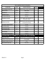
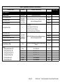
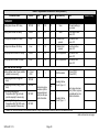
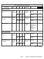
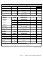
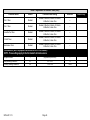
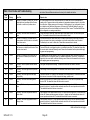
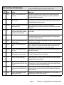
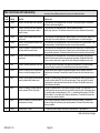
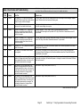
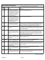
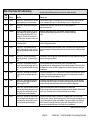
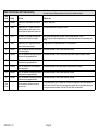
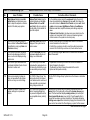
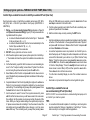
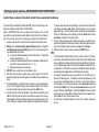
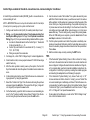
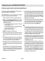
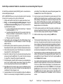
Table 3. Adjustable Parameters Table (Installer)
Parameter Name
Default
Min.
Max.
Incr.
Dependency
Note
Installer entry
Other Parameters
Equipment Name
Continuous Indoor Blower Airflow
Humidification Airflow
Dehumidification Airflow Percentage
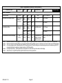
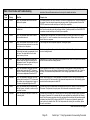
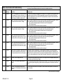
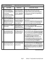
Note 1:
Note 2:
Note 3:
Note 4:
Note 5:
Furnace
N/A
N/A
N/A
None
Up to 35 characters
DIP SW (See
Note 3 at
end of table)
Min
CFM
Max
CFM
25
None
1/2 HP blower
Min
CFM
Max
CFM
25
Same as
above
Min
CFM
Max
CFM
25
Min
CFM
Max
CFM
25
120
(=60%)
160
(=80%)
2
(=1%)
140
(=70%)
1 HP blower
Humidifier present
1/2 HP blower
1 HP blower
OU present and SC
(Subnet Controller)
algorithm support
Percent of High Cooling
Airflow
Minimum Outdoor Unit Cooling Stage as a percentage of High Cooling Airflow (value is rounded up to the closest number on 25 CFM resolution.
Minimum Outdoor Unit Heating Stage as a percentage of High Heat Pump Airflow (value is rounded up to the closest number on 25 CFM resolution).
All communicating Installer Parameters default CFM values based on DIP switch setting (non−communicating value) are calculated using the CFM
conversion tables and rounded up to closest number on 25 CFM resolution.
Parameter dependency − Certain parameters are dependent on others and may not be shown on the display.
Default Values − Jumper/DIP switches impact the default value of some parameters.
507064−01 11/12
Page 42