1
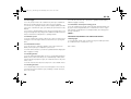
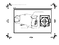
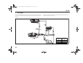
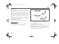
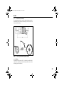
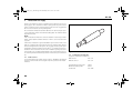
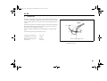
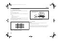
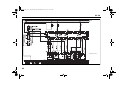
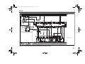
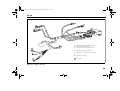
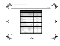
HL90 EA_de_en_fr.book Page 1 Wednesday, June 5, 2013 10:17 AM
Luftheizgeräte
Air heaters
Appareils de chauffage à air chaud
Einbauanweisung
Installation Instructions
Notice de montage
HL 90
HL90 EA_de_en_fr.book Page III Wednesday, June 5, 2013 10:17 AM
HL 90
Inhaltsverzeichnis
Table of contents
1
Gesetzliche Bestimmungen für den Einbau . . . . . . . . . . . . . . 1
1
Statutory regulations governing installation . . . . . . . . . . . .27
2
Verwendung der Luftheizgeräte . . . . . . . . . . . . . . . . . . . . . . 3
2
Use of the air heaters . . . . . . . . . . . . . . . . . . . . . . . . . . . . . .29
3
Montage des Heizgeräts . . . . . . . . . . . . . . . . . . . . . . . . . . . . 4
3
To install the heater . . . . . . . . . . . . . . . . . . . . . . . . . . . . . . .30
4
Fabrikschild . . . . . . . . . . . . . . . . . . . . . . . . . . . . . . . . . . . . . . 8
4
Factory plate . . . . . . . . . . . . . . . . . . . . . . . . . . . . . . . . . . . .34
5
Heizluftsystem . . . . . . . . . . . . . . . . . . . . . . . . . . . . . . . . . . . 9
5
Hot air system . . . . . . . . . . . . . . . . . . . . . . . . . . . . . . . . . . .35
6
Brennstoffversorgung . . . . . . . . . . . . . . . . . . . . . . . . . . . . . 10
6
Fuel supply . . . . . . . . . . . . . . . . . . . . . . . . . . . . . . . . . . . . . .36
7
Brennluftversorgung . . . . . . . . . . . . . . . . . . . . . . . . . . . . . . 14
7
Combustion air supply . . . . . . . . . . . . . . . . . . . . . . . . . . . . .40
8
Abgasleitung . . . . . . . . . . . . . . . . . . . . . . . . . . . . . . . . . . . . 15
8
Exhaust line . . . . . . . . . . . . . . . . . . . . . . . . . . . . . . . . . . . . .41
9
Elektrische Anschlüsse . . . . . . . . . . . . . . . . . . . . . . . . . . . . 16
9
Electrical connections . . . . . . . . . . . . . . . . . . . . . . . . . . . . . .42
10 Erstinbetriebnahme . . . . . . . . . . . . . . . . . . . . . . . . . . . . . . . 24
10 Initial start-up . . . . . . . . . . . . . . . . . . . . . . . . . . . . . . . . . . .50
11 Technische Daten . . . . . . . . . . . . . . . . . . . . . . . . . . . . . . . . 25
11 Technical data . . . . . . . . . . . . . . . . . . . . . . . . . . . . . . . . . . . .51
III
HL90 EA_de_en_fr.book Page 27 Wednesday, June 5, 2013 10:17 AM
HL 90
1
Statutory regulations governing installation
Type approvals according to ECE-R 10 (EMC) and ECE-R 122 (Heater) exist
for the HL 90 heater.
1.1. Extract from directive ECE-R 122 Part I and Annex 7
Start of extract.
See chapter 11, "Technical data" for the approval number.
Part I
Primarily the regulations of Annex VII of the Directive 2001/56/EG and Part I
and Annex 7 of the directive ECE-R 122 must be observed for the
installation.
5.3 Vehicle Installation Requirements for Combustion Heaters and
for Electric Heaters
NOTE:
The provisions of these Directives are binding within the territory
governed by EU Directive 70/156/EEC and should similarly be observed in countries without specific regulations!
IMPORTANT:
Failure to follow the installation instructions and the notes contained therein
will lead to all liability being refused by Webasto. The same applies if repairs
are carried out incorrectly or with the use of parts other than genuine spare
parts. This will result in the invalidation of the type approval for the heater
and therefore of its homologation / ECE type licence.
5.3.1 Scope
5.3.1.1 Subject to paragraph 5.3.1.2, heaters shall be installed according to
the requirements of paragraph 5.3.
5.3.1.2 Vehicles of category O having liquid fuel heaters are deemed to
comply with the requirements of paragraph 5.3.
5.3.2 Positioning of heater
5.3.2.1 Body sections and any other components in the vicinity of the heater
must be protected from excessive heat and the possibility of fuel or oil contamination.
5.3.2.2 The heater shall not constitute a risk of fire, even in the case of overheating. This requirement shall be deemed to be met if the installation ensures an adequate distance to all parts and suitable ventilation, by the use
of fire resistant materials or by the use of heat shields.
5.3.2.3 In the case of M2 and M3 vehicles, the combustion heater must not
be positioned in the passenger compartment. However, an installation in an
effectively sealed envelope which also complies with the conditions in paragraph 5.3.2.2 may be used.
5.3.2.4 The label referred to in Annex 7, paragraph 4, or a duplicate, must
be positioned so that it can be easily read when the combustion heater is
installed in the vehicle.
5.3.2.5 Every reasonable precaution should be taken in positioning the
heater to minimize the risk of injury and damage to personal property.
27
HL90 EA_de_en_fr.book Page 28 Wednesday, June 5, 2013 10:17 AM
HL 90
5.3.3 Fuel supply
5.3.3.1 The fuel filler must not be situated in the passenger compartment
and must be provided with an effective cap to prevent fuel spillage.
5.3.3.2 In the case of liquid fuel heaters, where a supply separate from that
of the vehicle is provided, the type of fuel and its filler point must be clearly
labelled.
5.3.3.3 A notice, indicating that the heater must be shut down before refuelling, must be affixed to the fuelling point. In addition a suitable instruction
must be included in the manufacturer’s operating manual.
5.3.4 Exhaust system
5.3.4.1 The exhaust outlet must be located so as to prevent emissions from
entering the vehicle through ventilators, heated air inlets or opening windows.
5.3.7.2 The air outlet must be so positioned or guarded that blocking by
rubbish or luggage is unlikely.
5.3.8 Automatic control of the heating system
5.3.8.1 The heating system must be switched off automatically and the supply of fuel must be stopped within five seconds when the vehicle’s engine
stops running. If a manual device is already activated, the heating system
can stay in operation.
ANNEX 7
ADDITIONAL REQUIREMENTS FOR COMBUSTION HEATERS
7 Warning light
7.1 A clearly visible tell-tale in the operator’s field of view shall inform when
the combustion heater is switched on or off.
5.3.5 Combustion air inlet
5.3.5.1 The air for the combustion chamber of the heater must not be
drawn from the passenger compartment of the vehicle.
5.3.5.2 The air inlet must be so positioned or guarded that blocking by rubbish or luggage is unlikely.
5.3.6 Heating air inlet
5.3.6.1 The heating air supply may be fresh or re-circulated air and must be
drawn from a clean area not likely to be contaminated by exhaust fumes
emitted either by the propulsion engine, the combustion heater or any other
vehicle source.
5.3.6.2 The inlet duct must be protected by mesh or other suitable means.
5.3.7 Heating air outlet
5.3.7.1 Any ducting used to route the hot air through the vehicle must be
so positioned or protected that no injury or damage could be caused if it
were to be touched.
28
End of extract.
HL90 EA_de_en_fr.book Page 29 Wednesday, June 5, 2013 10:17 AM
HL 90
2
Use of the air heaters
Webasto HL 90 are heaters are designed
– to heat the cab and the
passenger compartment
– to defrost the vehicle windows
– to heat vehicle bodies.
They are not designed for heating cargo areas used to carry hazardous substances.
The heaters operate independently of the engine and are connected to the
fuel tank and the electrical system of the vehicle.
They may be used for vehicles with either water or air-cooled engines.
29
HL90 EA_de_en_fr.book Page 30 Wednesday, June 5, 2013 10:17 AM
HL 90
3
To install the heater
The standard scope of delivery of the heater consists of:
– 1 Heater
– 2 Supports
– 2 Clamping bands
– 2 Turnbuckles
– 1 Intake manifold
– 1 Fuel metering pump
The heater must be installed on a flat surface as shown in Figures 1 and 2.
Make the hole pattern as shown in Figure 2.
The floor attachment can be aligned within the specified tolerances by loosening or tightening the turnbuckles and clamping bands.
The screws of the turnbuckles must be tightened to 5 Nm, the bolts (M8) of
the supports must be tightened to 12 Nm.
The installation dimensions and space requirement for service access are
shown in the installation drawing (Figures 1 and 2). The specified horizontal
and axial angles must not be exceeded.
The heater is not allowed to be installed in the passenger compartment.
If the heater is installed on the exterior, ensure that it is fitted in a position
where it is protected from splashing water and spray.
30
In the case of installations in which the heater surface could be touched inadvertently or flammable materials could come into contact with the heater
surface, it is obligatory to mount a shield (Webasto accessory) over the heat
exchanger, see Figure 2. For this purpose, the shield is clamped between the
support and the mounting surface in the vehicle, see Figure 3. The position
must be selected so the return pin on the temperature sensor can be reached
through the cut-out in the shield.
The air heater’s heat exchanger can be used for a maximum of 10 years and
must then be replaced by the manufacturer or one of its authorised workshops using a genuine spare part. A label must then be affixed to the heater
showing the date of sale of the heat exchanger and the wording “Genuine
spare part”. If exhaust pipes pass through compartments used by people,
the pipes must also be replaced by genuine spare parts after 10 years.
HL90 EA_de_en_fr.book Page 31 Wednesday, June 5, 2013 10:17 AM
HL 90
Figure 1:
Possible installation location
31
HL90 EA_de_en_fr.book Page 32 Wednesday, June 5, 2013 10:17 AM
HL 90
6
1
7
2
1 Heater
2 Support with clamping belt and turnbuckle
3 Exhaust outlet extension with
flex pipe, øi 38
4 Intake manifold (only required if
combustion air should be drawn
in directly from the outside, not via a
grille or gills)
5 Intake pipe extension with
flex. pipe, øi 30.5
6 Return pin on temperature limiter
7 Shield
(only required in certain installation
positions of the heater)
Figure 2:
32
Installation drawing
3
4
5
A Fuel connection with fuel hose
B5x9 DIN 73379
B Space required for removing
glow plug and flame monitor
C Hole pattern in the floor of the
installation space
Hole pattern only required if
part 4 is used
HL90 EA_de_en_fr.book Page 33 Wednesday, June 5, 2013 10:17 AM
HL 90
Hole in the shield for reaching the
return pin on the temperature limiter
Webasto accessory
Figure 3:
Shield is clamped under
the support
To install the shield
33
HL90 EA_en.fm Page 34 Thursday, July 4, 2013 11:44 AM
HL 90
4
Factory plate
The model plate must be positioned so that it cannot be damaged and must
be clearly legible when the heater is installed (otherwise a duplicate model
plate must be used).
The installer must ensure that the year of initial start-up is indelibly marked
on the model plate (see Figure 4).
Figure 4:
34
Factory plate corresponding to HL 90/24 V heater
HL90 EA_de_en_fr.book Page 35 Wednesday, June 5, 2013 10:17 AM
HL 90
5
Hot air system
Integrating the heater into an existing air system belonging to the vehicle requires careful harmonisation and is not recommended.
The air heater can be used both in fresh air mode for heating a passenger
compartment and a driver’s cab as well as in recirculated air/fresh air mode
for vehicle bodies. If the air heater is installed in a vehicle body for use in recirculated air mode, a sticker with the following content must be affixed to
the inside of the entrance door:
“No-one is allowed to remain in the enclosed loadspace when the heater is
switched on!”
The hot air hose must be secured at its connection points.
When used in recirculated air mode, measures must be taken to prevent the
heater sucking in its own heated air.
Due to the risk of poisoning and suffocation, the intake opening for the hot
air system must be arranged so that exhaust gases from the vehicle’s engine
and the heater itself cannot be sucked in under normal operating conditions.
This also applies even if a blower is used on the heater output side, e.g. by
sucking in air from the engine compartment.
The intake temperature of the heating air must not exceed +30 °C.
Minimum internal diameter of the hot air line:
100 mm
Maximum air pressure differential between the intake and outlet side of the
hot air line:
2.5 mbar (25 mm water column)
If these values are exceeded the temperature limiter will trip.
35
HL90 EA_de_en_fr.book Page 36 Wednesday, June 5, 2013 10:17 AM
HL 90
6
Fuel supply
The fuel is taken from the vehicle fuel tank or from a separate fuel tank. The
values for the maximum pressure at the fuel extraction point are shown in
Figure 5.
Figure 5:
36
Fuel supply
A sign must be affixed to the fuel filler neck warning that the heater must
be switched off before refuelling.
Maximum fuel intake height
S (m)
At max. negative
pressure (bar) in fuel
tank
0.00
-0.10
0.50
-0.06
1.00
-0.02
HL90 EA_de_en_fr.book Page 37 Wednesday, June 5, 2013 10:17 AM
HL 90
6.1. Fuel supply with fuel extractor
In vehicles with large engines (trucks), the fuel must be extracted from the
fuel tank or a separate, non-pressurised tank (see Figures 6 and 7). This separate fuel extractor precludes any effect of pressure.
Fuel extractor
Sealing ring
Hole pattern
Tank fitting
(extraction through tank fitting)
Plastic tank
* Only use a fuel extractor if the fuel tank is made from metal
Figure 6:
Webasto fuel extractor
Sealing ring
(extraction through tank drain screw)
Figure 7:
Fuel extraction from the plastic tank
37
HL90 EA_de_en_fr.book Page 38 Wednesday, June 5, 2013 10:17 AM
HL 90
6.2. Fuel lines
Only steel, copper and plastic lines of plasticised, light and temperature-stabilized PA 11 or PA 12 (e.g. Mecanyl RWTL) pursuant to DIN 73378 may be
used for the fuel lines.
Since the lines normally cannot be routed with a constant rising gradient,
the internal diameter must not be allowed to exceed a certain size. Air or gas
bubbles will accumulate in lines with an internal diameter of more than 4
mm and these will cause malfunctions if the lines sag or are routed downwards. The diameters specified will ensure that bubbles do not form.
The lines should not be routed downwards from the metering pump to the
heater.
Right
Clip
Wrong
Bubble
Unsupported fuel lines must be secured to prevent them sagging. They must
be installed in such a way that they cannot be damaged by flying road chippings and high temperatures (exhaust line).
Bubble
Connecting two pipes with a hose
The correct procedure for connecting fuel lines with hosing is shown in Figure 8.
Figure 8:
Pipe / hose connection
Ensure that there are no leaks!
6.3. Metering pump
The metering pump is a combined delivery, metering and shut-off system
and is subject to certain installation criteria (see Figure 8).
6.3.1.
Installation location
Before installing the metering pump, ensure that the maximum pressure occurring at the pickup point is no more than 0.2 bar.
It is advisable to install the metering pump in a cool place. The maximum
ambient temperature must not exceed +40 °C at any time during operation.
The metering pump and fuel lines must not be installed within range of the
radiated heat from hot vehicle parts. A heat shield must be used if necessary.
The pump should ideally be installed near the tank.
38
HL90 EA_en.fm Page 39 Thursday, July 4, 2013 11:35 AM
HL 90
6.3.2.
Installation and attachment
The metering pump must be secured with a vibration-damping mounting.
Its installation position is limited as shown in Figure 9 in order to ensure effective automatic bleeding.
Figure 9:
Metering pump without diaphragm damper
6.4. Fuel filter
Only a Webasto filter, order no. 487 171, is allowed to be used if the fuel is
expected to be contaminated. Install vertically if possible, however at least
horizontally (check flow direction).
39
HL90 EA_de_en_fr.book Page 40 Wednesday, June 5, 2013 10:17 AM
HL 90
7
Combustion air supply
Under no circumstances may the combustion air be taken from areas occupied by people. The combustion air intake opening must not point in the direction of travel. It must be located so that it cannot become clogged with
dirt or snow and cannot suck in splashing water.
The combustion air intake line (internal diameter min. 30 mm) may be up to
5 m in length and contain several bends totalling 360°. The minimum bending radius is 45 mm.
NOTE:
If the combustion air intake line cannot be installed so that it slopes downwards, a water drain hole with a diameter of 4 mm is to be made at its lowest point.
If the heater is installed in a general installation space near the vehicle’s fuel
tank, the combustion air must be taken in from the outside and the exhaust
fumes discharged into the atmosphere. The openings must be splash-proof.
A ventilation opening measuring at least 10 cm2 is required if the heater is
installed in an enclosed box. The size of the ventilation opening must be increased subject to consultation with Webasto if the temperature in the box
exceeds the permitted ambient temperature of the heater (see Technical data).
7.1. Intake silencer
It is recommended for the intake silencer (order no. 198 56A) to be installed
in order to reduce intake air noise (Figure 10). This is placed on the intake
manifold.
40
Figure 10:
Intake silencer
7.2. Combustion air intake line
Length of combustion air intake line
With silencer:
max. 3 m
Without silencer:
max. 5 m
Internal diameter of the lines:
30 mm
Minimum bending radius:
45 mm
Total bends:
max. 360°
HL90 EA_de_en_fr.book Page 41 Wednesday, June 5, 2013 10:17 AM
HL 90
8
Exhaust line
Rigid pipes of unalloyed or alloyed steel with a minimum wall thickness of
1.0 mm or flexible piping of alloyed steel only must be used as the exhaust
line. The exhaust pipe is secured to the heater using a clamping collar, for
example.
Front
It must not be possible for condensate or water to collect in the exhaust line.
Drain holes may be used; these must channel the fluid to the outside via
pipes that are sealed towards the interior.
max. 80°
See the “Statutory regulations governing installation” for further regulations.
The heater may also be operated with a silencer.
Length of the exhaust line:
max. 80°
max. 80°
max. 5 m
Internal diameter of the line:
38 mm
Minimum bending radius:
85 mm
Total bends:
max. 360°
Preferred discharge direction
Figure 11:
Exhaust pipe opening
(Installation position)
41
HL90 EA_de_en_fr.book Page 42 Wednesday, June 5, 2013 10:17 AM
HL 90
9
Electrical connections
9.1. Control unit / heater connection
The electrical connection of the heaters is made as shown in Figures
16 to 18.
Blade-type fuse holder
ID no. 148 78A
9.2. Connecting the controls
The heater can be switched on and off using the following Webasto controls:
-
Switch
-
Cabin thermostat (mechanical)
-
Digital timer (24 hour)
If a digital timer is used, the 8-pin blade terminal type AMP 163-007-0
ID no. 178 764 must be ordered separately.
The controls are connected in accordance with the sample applications
shown in Figures 19 and 20.
Figure 13:
9.3.
Figure 12:
42
12 V
24 V
F1
20 A
20 A
F2
20 A
20 A
F3
10 A
7.5 A
Blade-type fuses (overview)
Fuse holder (installation position)
Control unit
NOTE
Control units for the 12 volt version have red lettering, those for the
24 volt version have green lettering.
Fit an insulation housing onto the blade receptacles when connecting to the
switch due to the risk of a short circuit. The cable bridges required for connection should be made yourself as shown in the connection diagram.
HL90 EA_de_en_fr.book Page 43 Wednesday, June 5, 2013 10:17 AM
HL 90
For plugs, see circuit diagrams Figure 16 to Figure 20
Cable colours
bl
br
ge
gn
gr
or
rt
sw
vi
ws
Figure 14:
Blue
Brown
Yellow
Green
Grey
Orange
Red
Black
Violet
White
Plug connector
43
HL90 EA_de_en_fr.book Page 44 Wednesday, June 5, 2013 10:17 AM
HL 90
Item
Designation
A1
A1
A2
A2
B1
B2
B3
E
F1
F1
F2
F2
F3
F3
H1
H1
H2
H2
H3
H4
H5
K1
K2
K3
K4
K5/K6
K5/K6
M
HL 90 heater
24 V
HL 90 heater
12 V
Control unit
24 V
Control unit
12 V
Flame monitor
12/24 V
Temperature limiter
12/24 V
Cabin thermostat
12/24 V
Glow plug
4V
Blade-type fuse
24 V
20 A
Blade-type fuse
12 V
20 A
Blade-type fuse
24 V
20 A
Blade-type fuse
12 V
20 A
Blade-type fuse
12 V
10 A
Blade-type fuse
24 V
7.5 A
Switch-on indicator heating 24 V
Switch-on indicator heating 12 V
Switch-on indicator heating/ventilation 12/24 V
Switch-on indicator heating/ventilation 12/24 V
Symbol light for digital display
Ready indicator heating
Switch-on indicator heatRelay
In control unit
Relay
In control unit
Relay
In control unit
Relay
In control unit
Relay (as required)
24 V
Relay (as required)
12 V
Motor
24 V
Figure 15:
44
Comment
Legend to the circuit diagrams Figure 16 to Figure 18
Item
Designation
M
P
P
R1
R1
R2
R2
S1
S2
S3
S4
S5
S6
T
XA
XB
XC
X00
X0
X1
X2
X3
X4
X5
X6
X7
X8
Y
Y
Motor
12 V
Digital timer 1522
24 V
Digital timer 1522
12 V
Resistor
24 V
Resistor
12 V
Glow plug series resistor.
24 V
Glow plug series resistor
12 V
4-stage switch
On/off switch
Full load/part load heating switch
Full load/part load heating thermostat
Full load/part load ventilation switch
Battery switch
In vehicle
Transistor
In control unit
Plug connection for recep6-pin
Plug connection for recep2-pin
Plug connection for recep14-pin
Terminal connection
Glow plug Terminal connection
Glow plug +
Plug connection
1-pin
Plug connection
2-pin
Plug connection
2-pin
Plug connection
2-pin
Plug connection
2-pin
Plug connection
2-pin
Plug connection
4-pin
Plug connection
8-pin
Metering pump
24 V
Metering pump
12 V
Comment
HL90 EA_de_en_fr.book Page 45 Wednesday, June 5, 2013 10:17 AM
HL 90
1,5mm2
58
1,5mm2
75 (15)
4mm2
30
58
75 (15)
30
K6
XA
ge
A2
K4
3
0,75mm2
S3
X6
1
1
X7
X5
2
4
bl
WS
3
H1
Y
rt
A1
2
1
4
rt/bl
R1
B2
4mm2
31
3
0,75mm2
0,75mm2
br
XB
*) Digital timer P
2
1
2
M
M
1
2
X00
R2
2,5mm2
br 2,5mm2
X3 0,75mmbr
X4
2
1
S4
4
2
gn
0,75mm2
XC
2
br 0,75mm2
5
1
0,75mm2
br
or
S2
14
X2
bl 1mm2
B3
br 1mm2
1
12
1,5mm2
8
4
2
ge 1,5mm2
5
10
sw
gn
T
5
ge
H5
br
6
vi 1,5mm2
sw 1mm2
P
1
vi
br
H3 H4
K1
K2
K3
rt 1,5mm2
6
6
bl 0,75mm2
sw
1
2
2
rt/bl 0,75mm2
bl/g e
gn 1mm2
vi
0,75mm2
*)
0,75mm2
4
9
2,5mm2
31a
X8
X1
with positive at connection 9:
Continuous operation on
immediate heating
without positive at connection
9:
Heating duration 1 hour
1,5mm2
31a
F2
F1
1,5mm2
K5
* Deleted in 12 V
X0
B1
ge
E
31
4mm2
S6
Figure 16:
Operation with digital timer and cabin thermostat
45
HL90 EA_de_en_fr.book Page 46 Wednesday, June 5, 2013 10:17 AM
HL 90
* Deleted in 12 V
Figure 17:
46
Operation with switch (full load/part load) and ventilation
HL90 EA_de_en_fr.book Page 47 Wednesday, June 5, 2013 10:17 AM
HL 90
* Deleted in 12 V
Figure 18:
Operation with cabin thermostat (full load/part load) and ventilation
47
HL90 EA_de_en_fr.book Page 48 Wednesday, June 5, 2013 10:17 AM
HL 90
Connection of control unit / fuse holder / switch
1
2
3
4
6
17
7
Figure 19:
48
Sample application in conjunction with automatic circuit diagram
Control unit
Fuse holder
To battery (+)
Earth (-)
Switch
Remove the two white locking pins
Switch-on indicator (heating and ventilation)
HL90 EA_de_en_fr.book Page 49 Wednesday, June 5, 2013 10:17 AM
HL 90
X2
X3
X4
Metering pump intermediate plug connection
Flame monitor plug connection
Glow plug series resistor plug connection
X5
Temperature limiter plug connection
X7
Motor plug connection, motor series resistor
X0;
X00 Glow plug connection
1
Figure 20:
Control unit
Sample connection
49
HL90 EA_de_en_fr.book Page 50 Wednesday, June 5, 2013 10:17 AM
HL 90
10
Initial start-up
After you have installed the heater, bleed the fuel supply system carefully.
NOTE
If the fuel lines are long, it may be necessary to switch on several times in
order to fill the fuel line to the heater.
Conduct a trial of the heater to check all the connections for leaks and to
ensure that they are secure. If the heater suffers a fault during operation, the
fault must be located and remedied.
50
HL90 EA_de_en_fr.book Page 51 Wednesday, June 5, 2013 10:17 AM
HL 90
11
Technical data
Except where limit values are specified, these technical data refer to the usual heater tolerances of ±10 % at an ambient temperature of +20 °C and at
the rated voltage.
11.1. Electrical components:
Control unit, motor, metering pump, glow plug series resistor, part load resistor, digital timer and switch with lamp are designed for either 12 V or
24 V.
The temperature limiter, flame monitor and glow plug components are identical on 12 V and 24 V heaters.
The nominal voltage of the glow plug is 4.2 V.
51
HL90 EA_de_en_fr.book Page 52 Wednesday, June 5, 2013 10:17 AM
HL 90
Heater
Type
ECE homologation
Model
Heating current
Fuel
Fuel consumption
Full load kW
Part load kW
Full load kg/h (l/h)
Part load % by vol.
Rated voltage
VOperating voltage
VRated power consumption
Full load W
(not in starting operation)
Part load W
Max. ambient temperature during operation:
- Heater
°C
- Control unit
°C
- Metering pump
°C
Max. storage temperature:
- Heater
°C
- Control unit
°C
- Metering pump
°C
Max. hot air inlet temperature
°C
Delivery rate for hot air
against 0.5 mbar at
full load m3/h
against 0.25 mbar at
part load m3/h
CO2 in exhaust gas (at full load):
- Permitted function range
% by vol.
CO in exhaust gas - In still air
% by vol.
- At 100 km/h
% by vol.
HC in exhaust gas (at rated load and in still air)
% by vol.
NOx in exhaust gas (at rated load and in still air)
% by vol.
Soot index
- Bacharach method
Heater dimensions:
Length
mm
(tolerance ±3 mm)
Width
mm
Height
mm
Metering pump dimensions:
Length
mm
(tolerance ±3 mm)
Width
mm
Height
mm
Control unit 1561 dimensions:
Length
mm
(tolerance ±3 mm)
Width
mm
Height
mm
Weights:
Heater
kg
Control unit
kg
Metering pump
kg
52
HL 90
HL 90
EMC:
E1 04 1086
Heater:
E1 00 0017
Air heater with rotation evaporator
9
6.5
Diesel/heating oil EL
1.00 (1.20)
0.71 (0.86)
12 or 24
10 ... 14.5 or 20.5 ... 29
110
80
-40 ... +50
-40 ... +85
-40 ... +40
-40 ... +85
-40 ... +85
-40 ... +85
+30 max.
280
195
7 ... 10
0.1 max.
0.2 max.
0.01 (100 ppm) max.
0.02 (200 ppm) max.
4.0
650
235
260
113
40
35
97
102
36
13
0.30
0.35
HL90 EA_de_en_fr.book Page 61 Wednesday, June 5, 2013 10:17 AM
Im Fall einer mehrsprachigen Version ist Deutsch verbindlich.
Die Telefonnummer des jeweiligen Landes entnehmen Sie bitte dem Webasto Servicestellenfaltblatt oder der Webseite Ihrer jeweiligen WebastoLandesvertretung.
In multilingual versions the German language is binding.
The telephone number of each country can be found in the Webasto service center leaflet or the website of the respective Webasto representative of your
country.
Dans le cas d'une version rédigée en plusieurs langues, l'allemand est alors la langue qui fait foi.
Pour trouver le numéro de téléphone du pays concerné, veuillez consulter le dépliant des points-service Webasto ou la page web de la représentation Webasto
de votre pays.
Webasto Thermo & Comfort SE
Postfach 1410
82199 Gilching
Germany
Visitors’ address:
Friedrichshafener Str. 9
82205 Gilching
Germany
Internet: www.webasto.com
Technical Extranet: http://dealers.webasto.com
Nur innerhalb von Deutschland
Tel.:
0395 5592 444
E-mail: [email protected]
Ident-Nr. 9012035B • 06/13 • Errors and omissions excepted • Printed in Germany • © Webasto Thermo & Comfort SE, 2013
HL90 EA_de_en_fr.book Page 62 Wednesday, June 5, 2013 10:17 AM