1
HL90 EA_de_en_fr.book Page 42 Wednesday, June 5, 2013 10:17 AM
HL 90
9
Electrical connections
9.1. Control unit / heater connection
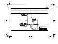
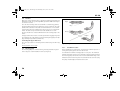
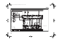
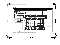
The electrical connection of the heaters is made as shown in Figures
16 to 18.
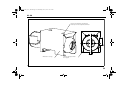
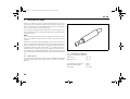
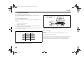
Blade-type fuse holder
ID no. 148 78A
9.2. Connecting the controls
The heater can be switched on and off using the following Webasto controls:
-
Switch
-
Cabin thermostat (mechanical)
-
Digital timer (24 hour)
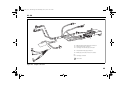
If a digital timer is used, the 8-pin blade terminal type AMP 163-007-0
ID no. 178 764 must be ordered separately.
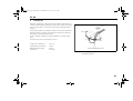
The controls are connected in accordance with the sample applications
shown in Figures 19 and 20.
Figure 13:
9.3.
Figure 12:
42
12 V
24 V
F1
20 A
20 A
F2
20 A
20 A
F3
10 A
7.5 A
Blade-type fuses (overview)
Fuse holder (installation position)
Control unit
NOTE
Control units for the 12 volt version have red lettering, those for the
24 volt version have green lettering.
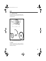
Fit an insulation housing onto the blade receptacles when connecting to the
switch due to the risk of a short circuit. The cable bridges required for connection should be made yourself as shown in the connection diagram.