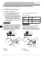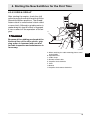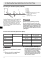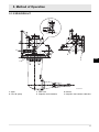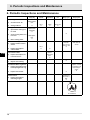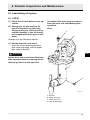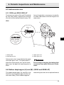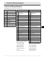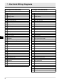
1
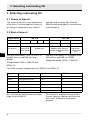
SD-Series
SAIL-DRIVE
MODEL: SD20, SD50/SD50-4T
OPERATION MANUAL
EN
Applicable Engine Model:
1GM10C, 2YM15, 3YM20, 3YM30, 3JH4E, 4JH4E 4JH3-TCE
All rights reserved. This manual may not be reproduced or copied, in whole or in part,
without the written permission of YANMAR CO., LTD.
Copyright © 2004 Yanmar CO., LTD
Introduction ................................................... 3
1. For Your Safety ........................................ 4
1.1 Safety Precautions For Inspection .... 4
2. Specifications ........................................... 7
3. Selecting Lubricating Oil ........................... 8
3.1 Choice of lube oil .............................. 8
3.2 Kind of lube oil .................................. 8
3.3 Lube oil viscosity ............................... 9
EN
4. Starting the New Sail-Drive for the First
Time .................................................. 10
4.1 Filling with lubricating oil ................. 10
4.1.1 SD20 and SD50/-4T .............. 10
4.2 Check of instrument panel alarm system: 11
4.3 Remote-Control Device Check ........ 12
4.4 Fitting for Fixed Propeller (2-blade) . 14
4.5 Recommended Propeller Size (Max.) .
14
5. Method of Operation .............................. 16
5.1 Engine Cooling Water ..................... 16
5.1.1 SD20 ..................................... 16
5.1.2 SD50/SD50-4T ...................... 17
6. Periodic Inspections and Maintenance ... 18
6.1 Lubricating oil system ...................... 19
6.1.1 SD20 ..................................... 19
6.1.2 SD50/-4T ............................... 20
6.2 Procedure for filling and removing oil in
the Sail-Drive; SD50/-4T 21
6.2.1 When the boat is in the water 22
6.2.2 When the boat is out of the water
26
6.3 Anticorrosive zinc ............................ 29
6.3.1 SD20 and SD50/ SD50-4T .... 29
6.4 Rubber diaphragms (A) and (B) (SD20
and SD50/-4T) 29
6.5 When the boat hull is raised onto a
block, inspect the following: 30
7. Electrical Wiring Diagrams ......................31
Introduction
This Installation and Operation Manual describes Sail-Drive Models SD20, SD50,
SD50-4T.
For engine handling and operation, refer to the respective operation manuals for Engine
Models 1GM10C, 2YM15, 3YM20, 3YM30, 3JH4E, 4JH4E and 4JH3-TCE. However, instructions for the marine gear box are not necessary as they are included.
Engines and sail-drive combinations are available as follows:
Engine model
Sail-drive model
1GM10C
SD20
2YM15
3YM20, 3YM30
3JH4E
SD50
4JH4E
4JH3-TCE
SD50-4T
EN
3
1. For Your Safety
1. For Your Safety
1.1 Safety Precautions For Inspection
DANGER
Battery
Never smoke or permit sparks near the battery, because it may emit explosive hydrogen gas. Place the battery in a well-ventilated place.
DANGER
Fuel
Use only diesel fuel. Never use other fuels, including gasoline, kerosene, etc., because they could cause a fire. The wrong fuel could also
cause the fuel injection pump and injector to fail due to lack of proper
lubrication. Be sure to check that you have selected the correct diesel
fuel before filling the fuel tank.
Do not use starting fluids or sprays. Their use may cause explosion, serious injury and engine damage.
WARNING
Fire Prevention
Be sure to stop the engine and confirm that there are no open flames in
the vicinity before fueling. If you do spill fuel, wipe such spillage carefully and dispose of the wiping materials properly. Wash your hands thoroughly with soap and water.
Never place oil or other flammable material in the engine room.
Install a fire extinguisher near the engine room, and familiarize yourself
with its use.
WARNING
Exhaust Gas
Exhaust gas contains poisonous carbon monoxide and should not be
inhaled.
Be sure to install ventilation ports or ventilators in the engine room and
ensure good ventilation during engine operation.
WARNING
Moving Parts
Do not touch or let your clothing get caught in the moving parts of the
engine, such as the front drive shaft, V-belt or propeller shaft, during engine operation. You will be injured.
Never operate the engine without covers on the moving parts.
EN
4
1. For Your Safety
CAUTION
Burns
The whole engine is hot during operation and immediately after
shut-down. The exhaust manifold, exhaust pipe and high pressure fuel
lines are very hot. Never touch these parts with your body or clothing.
WARNING
Alcohol
Never operate the engine while you are under the influence of alcohol.
Never operate the engine when you are ill or not feeling well.
DANGER
Battery Fluid
Battery fluid is dilute sulphuric acid. It can blind you if it gets in your
eyes, or burn your skin. Keep the fluid away from your body.
If you touch it, wash it off immediately with a large quantity of fresh water and call your doctor for treatment.
WARNING
Fire by Electric Short-Circuits
Always turn off the battery switch before inspecting the electrical system.
Failure to do so could cause short-circuiting and fires.
WARNING
Stop the engine before you service it.
Turn the battery switch off. If you must inspect while the engine is in operation, never touch moving parts. Keep your body and clothing well
clear of all moving parts.
CAUTION
Scalds
When extracting oil from the engine while it is still hot, don't let the oil
splash on you.
Wait until the temperature has dropped before extracting cooling water
from the engine. Don't let it splash on you.
5
EN
1. For Your Safety
EN
6
DANGER
Forbidden Modifications.
Never release the limiting devices such as the engine speed limit, fuel
injection limit, etc.
Modification will impair the safety and performance of the product and
shorten product life.
Also note that any troubles arising from modification are not covered by
our warranty.
DANGER
Precautions for Treating Waste.
Never dispose of waste oil or other fluid in a field, sewer, river, or the
sea.
Treat waste matters safely observing regulations or laws.
Ask a waste recovery company to collect it.
2. Specifications
2. Specifications
Model
SD20
Reduction gear system
Direction of
rotation
SD50
Input shaft
Propeller shaft
SD50-4T
Constant mesh gear with
dog clutch use
Cone clutch
Counter-clockwise viewed from stern
Counter-clockwise viewed
from stern
Counter-clockwise or clockwise viewed from
stern
Reduction ratio Ahead
2.64
2.32
Astern
2.64
2.32
Propeller speed (min-1)
1364
Lubrication system
Lubrication oil
capacity
1638
Oil bath type
Standard unit
2.2 L
2.2 L
Long-reach
unit
2.5 L
2.35 L (Extension 58), 2.45 L (Extension
100)
Dry weight
Remote-control device
1293
30 Kg
Control head
Cable
Applicable engine model (Fuel
stop power at crankshaft)
39 kg
41 kg
Single control lever
"MORSE" 33C (equivalent)
4JH3-TCE
3JH4E
1GM10C (6.7kW/3600
(29.4 kW/3000 min-1) (55.2kW/3800min-1)
min-1)
4JH4E
2YM15 (10.3kW/3600 min-1)
3YM20 (16.2kW/3600 min-1) (40.5 kW/3000 min-1)
3YM30 (22.1kW/3600 min-1)
Note: A propeller with rubber bushing must be used in all SD series sail-drives.
7
EN
3. Selecting Lubricating Oil
3. Selecting Lubricating Oil
3.1 Choice of lube oil
The choice of lube oil is very important to
a Sail-Drive. If an unsuitable oil is used, or
oil change is neglected, it may result in
damage, and a shorter Sail-Drive life.
When selecting the lube oil, it must be one
of the following:
3.2 Kind of lube oil
Engine series
GM, YM
Engine model
1GM10C
2YM15
Sail-drive model
3YM20
3YM30
SD20
Lubrication oil for
the sail-drive
EN
JH3, JH4
API CC or
greater and
SAE 10W30
API GL4 or GL5 and SAE
80W90 or 90
Use only oil of quality “GL-4" or "GL-5" in
the API service, and SAE No. 90 or
80W90.
3JH4E
4JH4E
4JH3-TCE
SD50
SD50
SD50-4T
API GL4 or GL5 and SAE
80W90 or 90 or Quicksilver High Performance Gear
Lube
Quicksilver
High Performance Gear
Lube
Use only oil of quality "cc" or greater in the
API service, and SAE no. 10W30.
(Applicable model: SD20 x 1GM10C)
(Except model SD20 x 1GM10C and
SD50/-4T)
For SD20 (except if coupled with the 1GM10C) and SD50/-4T
Supplier
Brand Name
API Service
SAE No.
SHELL
Shell Spilax oil EP 90
GL-4
90
SHELL
Shell Spilax oil HD 90
GL-5
90
CALTEX
Multipurpose thuban EP
GL-4/GL-59
90
MOBIL
Mobilub HD 80W-90
GL-5
80W-90
ESSO
Esso gear oil GP 90
GL-4
90
ESSO
Esso gear oil GX 90
GL-5
90
Use "Quicksilver High Performance Gear
Lube" for the SD50/-4T.
8
This lube oil is available through all MerCruiser, Mercury, Mariner and Force outlets in their Quicksilver accessories
program.
3. Selecting Lubricating Oil
This High Performance Gear Lube is available in the following sizes:
Volume
Part number Package
300 ml
92-802851Q1
case of 24 tubes
1L
92-802854Q1
case of 12 plastic
bottles
10 L
92-802856Q1
case of 2 cans
60.5 L
92-802857Q1
single drum
208 L
92-802858Q1
single drum
3.3 Lube oil viscosity
The viscosity of the lube oil greatly influences Sail-Drive performance
EN
9
4. Starting the New Sail-Drive for the First Time
4. Starting the New Sail-Drive for the First Time
4.1 Filling with lubricating oil
4.1.1 SD20 and SD50/-4T
(1) Remove the dipstick (yellow cap)
and supply approved lube oil.
Sail-Drive Model:SD20 & SD50/-4T
(2) Check the amount of lube oil by inserting the dipstick as far as possible. Do not screw the dipstick in.
(see the illustration below). The oil
level should reach the upper mark
on the dipstick.
Lube oil capacity:
Sail-drive
model
SD20
SD50/-4T
Standard unit
2.2 L
2.2 L
Long-reach
unit
2.5 L
2.35 L (Extension 58)
2.45 L (Extension 100)
CAUTION
EN
Since it takes about 10 minutes to fill up
the Sail-Drive with lube oil, owing to its
construction, check the supplied oil
quantity again by using the dipstick 15
minutes after completion of supply of
the specified quantity of oil.
A
B
CAUTION
The lube oil capacity of the standard
unit is different from that of the
long-reach unit. Confirm the capacity
by means of the oil capacity nameplate.
A
C
B
D
C
D
E
E
F
F
SD20
SD50/SD50-4T
003443-00E
A Dipstick
B Upper limit
C Lower limit
10
D Oil level
E Oil supply port
F Oil capacity nameplate
4. Starting the New Sail-Drive for the First Time
4.2 Check of instrument panel alarm system:
Turn on the battery switch. Then the key in the "ON" position and check the lamps on the
panel (with the engine off).
(A-type)
(B-Type)
2
3
4
8
2
1
4
3
1
OFF
7
1 Rubber seal (Sail-Drive)
2 CW temp
3 Charge
6
5
6
4 LO press
5 Key switch
6 Warning Buzzer
(1) Lube oil warning lamp should be lit.
(2) Cooling water temperature warning
lamp should be out. (For small type
panel: A-type only)
For the large type panel (B-type), raise
the CHECK switch "ON" to see if the
cooling water temperature warning
lamp lights.
(3) Charging warning lamp should be
lit.
(4) Rubber seal lamp should be out.
7
9 5
7 Push button
8 Tachometer
9 Check switch
on the instrument panel. If this happens, stop the engine and, under sail,
quickly return to the nearest port for repairs.
CAUTION
All the above alarm signs will continue
until you push the starting button or
turn the key off.
A
B
C
D
E
F
A
(5) The warning buzzer should sound.
WARNING
The rubber seal alarm lamp warns of
seawater entering the boat. The watertight structure of the Sail-Drive is the
dual type. Even if the rubber diaphragm
(A) is damaged and seawater enters,
the rubber diaphragm (B) prevents it
from entering the inboard. The rubber
seal switch between the rubber diaphragms (A) and (B) works the warning
buzzer and lights the rubber seal lamp
ON
ON (Rubber seal lamp)
Buzzer
Rubber seal switch
Diaphragm (B)
Diaphragm (A)
Seawater
B
C
D
E
F
003446-00E
11
EN
4. Starting the New Sail-Drive for the First Time
4.3 Remote-Control Device Check
4.3.0.1 SD20
While cranking the engine slowly, shift the
control handle of the remote-control head
(single lever control) rapidly through Neutral - Ahead - Neutral - Astern. If a shift operation is done slowly, the tip of the clutch
dog is worn away by being hammered,
B
A
and, consequently, the clutch fails to engage. Confirm that the operation lever of
the Sail-Drive moves smoothly to Ahead,
Astern and Stopper. Because the
Sail-Drive SD20 uses a dog clutch, the
clutch is not engaged unless the operation
lever is moved to the stopper position.
M
C
N
L
O
D
R
E
EN
P
Q
S
F
T
U
Old type :
Serial No. 0001-2128 for SD10
D
G
H
I
J
K
New type :
Serial No. 2129 and after for SD20
003447-00E
New type: Serial No. 2129 and after for SD20
A Control handle
B Astern
C Neutral
D Ahead
E Operation lever
F Cable clamp
G Remote control cable
H Pivot
I Astern
J Neutral
K Ahead
12
Old type: Serial No. 0001-2128 for SD10
L Ahead stopper
M Neutral position
N Astern stopper
O Cable clamp
P Remote control cable
Q Spring joint
R Operation lever
S Astern
T Neutral
U Ahead
4. Starting the New Sail-Drive for the First Time
4.3.0.2 SD50 & SD50-4T
After starting the engine, check the shift
action by using the control head to shift the
Ahead and Astern positions. The Ahead/
Astern clutch is a mechanical clutch called
a cone clutch. Although a grinding noise is
made when this type of clutch is engaged,
it has no effect on the operation of the engine.
A
B
C
CAUTION
Because of the rubbing produced at the
frictional face of the cone clutch, gripping action is lessened with use and
periodic inspection and maintenance is
necessary.
D
E
F
G
H
003448-00E
A When attaching the cable mounting plate at a 90º
angle handle
B Operation lever
C Cable clamp
D Remote control cable
E Propeller shaft clockwise
F Pivot
G Neutral
H Propeller shaft counter-clockwise
13
EN
4. Starting the New Sail-Drive for the First Time
4.4 Fitting for Fixed Propeller (2-blade)
A
B
C
D
E
Spacer
Grease
Washer
Propeller
Nut Tightening torque 60-70 Nm (M16,
SD20)
80-100 Nm (M20, SD50/-4T)
F Bolt M8x75mm
Tightening torque11-15 Nm
E
C
A
B
F
D
003449-00E
Locking Procedure for Fixed Propeller Nut
(Optional). When tightening the nut at
60-70 Nm torque for the SD20, and 80-100
Nm torque for the SD50/-4T, move the
shift lever to ahead and hold the crankshaft V-pulley clamp nut with a wrench to
stop the rotation.
EN
CAUTION
Rubber bushing (Folding propeller)
For the sail-drive, be sure to use the
folding propeller which is provided with
a rubber bushing. If a propeller is used
without rubber bushing, the shaft, bearing, and gears of the sail-drive are surely damaged.
4.5 Recommended Propeller Size (Max.)
Engine model
Sail-Drive Model
Folding type Dia. mm
(inch)
2-blade, fixed typeDia. mm (inch)
SD20
355 (14)
380 (15)
2YM15
368 (14.5)
380 (15)
3YM20
380 (15)
405 (16)
3YM30
405 (16)
420 (16.5)
457 (18)
457 (18)
457 (18)
457 (18)
457 (18)
457 (18)
1GM10C
3JH4E
SD50
4JH4E
4JH3-TCE
SD50-4T
CAUTION
Precautions on matching of the propeller
(1) Be sure to confirm a matching of
the propeller in a sea trial.
14
(2) Execute a propeller matching on
the basis of the propeller shaft rated output (continuous rating at propeller shaft). 95% of the engine
rated output (continuous rating at
crankshaft) becomes the propeller
shaft rated output (continuous rating at propeller shaft).
4. Starting the New Sail-Drive for the First Time
Note: The propeller shaft output becomes
95% of the engine rated output (continuous
rating at crankshaft) in consideration of mechanical efficiency 95% of the sail-drive.
(3) In the case of propeller calculation,
further add 5%, at minimum, as the
sea margin to the aforementioned
matching point. That is, 95% of the
propeller shaft rated output (Continuous rating at propeller shaft)
becomes the best propeller matching. Note about sea margin: In actu-
al navigation, there is an increase
in resistance due to the waves,
wind and fouling of the hull and,
moreover, a drop in the efficiency
due to fouling of the propeller. Consequently, in the case of propeller
calculation, it is necessary to allow
the engine output to have some
margin. For that reason, it is necessary to add the sea margin of 5%, at
minimum.
EN
15
5. Method of Operation
5. Method of Operation
5.1 Engine Cooling Water
Note: For other items, refer to the engine operation manual.
Opening or closing the cooling water system of the Sail-Drive Set Engine is done by
the cooling water cock fixed on the upper
case of the Sail-Drive. Be sure to open the
cock and confirm that the C.W. has suction
by cranking the engine before starting the
boat. The cooling water passes through
the Sail-Drive case, cools the engine by
the cooling water pump, and is then discharged.
Note: When sailing, set the remote control lever
in neutral.
Old type:
Serial No.0001-2128 for Model SD20
New type:
Serial No.2129 and after for Model SD20
5.1.1 SD20
EN
E
D
F
A
G
B
H
C
D
I
003442-00E
A Atern
B Neutral
C Ahead
16
D Neutral
E Cock, C.W.
F C.W. hose
G To C.W. pump
H Hose clamp
I Seawater inlet
5. Method of Operation
5.1.2 SD50/SD50-4T
A
40
B
D
40
E
EN
F
C
003450-00E
A Open
B To C.W. pump
C Cock C.W.
D Propeller shaft Clockwise
E Neutral
F Propeller shaft Counter-clockwise
17
6. Periodic Inspections and Maintenance
6. Periodic Inspections and Maintenance
Every day
50 hrs. or after
1 month
Every 100 hrs.
Every 250
hrs.
First
O
SD20
O
SD50/-4T
O
Every 1 year
Every 2 years
Lubricating Oil
(1)
Check oil level: fill
(2)
Change lube oil
Before operation
O
Cooling Water
(1)
Open/close cooling water cock
(2)
Clean cooling water suction hole
(3)
Drain cooling water
Before/after
operation
O
O
After operation
O
Remote Control System
EN
(1)
Inspect remote control
device
(2)
Inspect and replace
clutch shifter
Anti-Corrosive Zinc
(1)
Inspect and replace anti-corrosive zinc
First
O
Replace if
the thickness is less
than 10 mm.
O
Serial No. 2129
and after for
SD20
O
Replace if
wear is
more than
50%
O
Lower Case
(1)
Repair case coating
O
Inspect and
replace, if there
is cracking, or at
least every 6
years
O
Boat Bottom Water- tightness
(1)
Inspect and replace rubber diaphragm seal ring
(2)
Inspect seal sensor
Flexible mount
(1)
Inspect and replace
mounting height.
O
Replace if
clearance is
less than 1
mm.
O
A
003451-00E
A: Clearance
18
6. Periodic Inspections and Maintenance
6.1 Lubricating oil system
6.1.1 SD20
(1) Check the oil level before every operation.
(2) Change the oil after the first 50
hours of operation or after long
storage and every 100 hours of operation thereafter. Lube oil should
be changed while the engine is still
warm.
forcefully if the drain plug is removed
from the drive unit immediately after
operation.
SD20
A
B
Change oil in the following manner:
(1) Put the boat hull on a block.
Drain the oil by removing the lower
gear case drain plug, and the upper
gear case oil dipstick.
EN
WARNING
Let the drive unit cool at least 5 minutes
after operation before removing the oil
drain plug. Hot oil could spurt out
C
D
003440-00E
A
B
C
D
Dipstick
Upper gear case
Lower gear case
Lube oil drain plug
19
6. Periodic Inspections and Maintenance
6.1.2 SD50/-4T
(1) Check the oil level before every operation.
(2) Change the oil after the first 50
hours of operation or after long
storage, and every 250 hours of operation thereafter. Lube oil should
be changed while the engine is still
warm.
SD50/SD50-4T
A
WARNING
B
Let the drive unit cool at least 5 minutes
after operation before removing the oil
drain plug. Hot oil could spurt out
forcefully if the drain plug is removed
from the drive unit immediately after
operation.
EN
C
003441-00E
A Dipstick
20
B Plug
C Drain plug
6. Periodic Inspections and Maintenance
6.2 Procedure for filling and removing oil in the Sail-Drive; SD50/-4T
When the boat is (6.2.1) in the water and (6.2.2) out of the water
Used equipment:
Description
Part code
Quantity
Remarks
Bottle of Quicksilver High Performance Gear Lube from
MerCruiser
MerCruiser Part code
92-850743A1
2
Each bottle contains 0.946 liter of oil.
Mandatory for SD50/-4T. For other
models see page 8.
Market pump from MerCruiser
on bottle
MerCruiser Part code
91-85729A1
1
Adapter joint
196311-92960
1 (2)
O-ring for adapter
24311-000100
1 (2)
Stiff rubber hoses
Compressor set
Hand pump
2
-
1
28210-000080
1
Thread std. M10 x 1.5 max. length 12
mm.
Inner diameter ø14-16 mm + hose
clips (If Yanmar part is used, part code
is 196440-92970)
EN
Option parts
21
6. Periodic Inspections and Maintenance
6.2.1 When the boat is in the water
6.2.1.1 Preparing the sail-drive:
A
6.2.1.2 Removing oil (total quantity
2.2 liter)
B
C
A
D
EN
003453-00E
003452-00E
A
B
C
D
O-ring
Adapter joint
Oil changing plug
Tread M10 x 1.5
(1) Take out the oil changing plug located under the shift lever.
(2) Screw in the adapter joint (19631192960) with the O-ring
(24311-000100). When using own
adapter joint, max. length of thread
is 12 mm.
(3) Attach a stiff rubber hose with inner
diameter ø14~16 mm with hose
clips to the adapter joint at the oil
changing position. Hose must be
long enough to drain to bucket or
pump. (If Yanmar original rubber
hose is used, part code is
196440-92970)
22
A Plug
6.2.1.3 Fastest way: Blowing out by
using Air pressure
First follow steps (1), (2), (3) on page 22
(1) Take out the plug from the upper
case cover.
(2) Screw in a second adapter joint (P/
N 196311-92960) with an O-ring (P/N
24311-000100) at the oil inlet position. Screw in the oil plug at the dipstick position.
(3) Connect the air pressure hose with
hose clips.
(4) Option 1: Using Compressed air
from main system or 12 V portable
compressor.
1. Connect hose at top adapter joint to
compressed air and within 10 to 15
minutes almost all oil will be blown out.
6. Periodic Inspections and Maintenance
A
B
(3) With the system now connected,
pump out the oil until empty. The
first 0.9 liter will take approx. 3 minutes. The second part takes more
time as mostly air will be pumped
out; this will take approx. 12 minutes.
6.2.1.4 Using Yanmar Pump
First follow steps (1), (2), (3) on page 22
and step (1) on page 22
C
003454-00E
A One-way valve
B Adapter joint screwed in cover
C Simple foot pump
Use Compressed Air (0.5~1 Bar) from
main system, 12 V portable compressor or from portable hand pump or foot
pump.
Option 2: Using Compressed air
with help from a portable hand
pump or foot pump
(1) Install a one-way (non return) valve
in the pressure line (connected to
the top cover). This is done to maintain the pressure during use of the
pump.
(2) Connect the hand pump or foot
pump with the pressure line to the
adapter joint on the top as shown
above.
Connect the hand pump with hoses as
shown above, and start pumping.
Be aware that oil has to flow down through
narrow parts and then up again.
Therefore, during this procedure, at first
suction pressure will be high and pumping
will be hard. A few minutes waiting in between will help. After taking out about 0.9
liter of oil, mostly you will pump out air, but
continuous pumping is necessary.
Though approx. 100-200 ml of old oil will
remain in the drive unit, in this case, it is no
problem to fill-up with the new oil for maintenance.
The hand pump (p/#:28210-000080) and
rubber hose (p/#:196440-92970) are available from Yanmar, and are optional parts
for SD50/-4T. Or any type of hand pump or
rubber hose (Inner diameter ø14-16 mm)
available from the hardware shop, are usable.
23
EN
6. Periodic Inspections and Maintenance
A
003455-00E
A Plug
EN 6.2.1.5 Filling oil (total quantity 2.2
liter)
The following methods of filling with lube
oil are in addition to the way mentioned in
page 10.
6.2.1.6 Fastest way: By using MerCruiser pump or simple market
pump
First follow steps (1) and (2) on page 22
(1) Use a MerCruiser pump with Part
number 91-85729A1 like the one
shown above or use a similar pump
available on the market.
24
(2) Screw the pump on a new bottle of
Quicksilver High Performance Gear
Lube Part number 92-850743A1
(0.946 liter) from MerCruiser.
(3) Connect the hose with a hose clip
to the adapter joint below the shift
lever.
(4) Take out the plug from the upper
case cover.
(5) Fill the oil by pushing the upper
part of the pump. After bottle is
empty, change the bottle while the
pump and hose remains connected
with the adapter joint.
(6) After filling, first screw in and tighten the plug at the top cover. Then
remove the oil bottle, pump, hose
and adapter joint and screw in the
oil plug (don't forget the gasket).
6. Periodic Inspections and Maintenance
6.2.1.7 By using Yanmar Hand
Pump
First follow steps (3) and (4) on page 24.
A
(2) Take out the plug from the upper
case cover.
(3) Fill in the oil moved by the hand
pump. Be aware that oil has to flow
down through narrow parts and
then up again. Therefore, during
this procedure, at first suction
pressure will be high and pumping
will be hard. A few minutes waiting
in between will help. The hand
pump (p/#: 28210-000080) and rubber hose (p/#: 196440-92970) are
available from Yanmar, and are optional parts for SD50/-4T. Or any
type of hand pump or rubber hose
(Inner diameter ø14-16 mm) available from the hardware shop, are
usable.
(4) After filling, first screw in and tighten the plug at the top cover. Then
remove the hand pump, hose and
adapter joint and screw in the oil
plug (don't forget the gasket).
003456-00E
A Plug
(1) Connect the hoses as shown above
at the top adapter joint to the hand
pump by using the rubber hose.
6.2.1.8 By not using pump
For the oil filling procedure by not using
pump, see the explanation on chapter 4.,
page 10.
25
EN
6. Periodic Inspections and Maintenance
6.2.2 When the boat is out of the
water
(4) Take out the dipstick and oil inlet
plug from the upper case cover.
6.2.2.1 Preparing the sail-drive:
6.2.2.2 Removing oil (total quantity
2.2 liter)
A
6.2.2.3 By draining
First follow steps (1), (2), (3), (4) on page
26.
Oil drain is possible from this point but will
take much time.
(1) After approx. 0.6 liter has been
drained, remove the oil changing
plug. If you remove sooner, oil may
spill out of this position (because
max. oil level is higher than this position).
EN
A
B
003458-00E
003457-00E
A Tread M10 x 1.5
B Oil changing plug
A Plug
(1) Remove the bottom drain plug
(2) Screw in the adapter joint (P/N
196311- 92960) with the O-ring (P/N
24311- 000100).
When using own adapter joint, max.
length of thread is 12 mm.
(3) Attach a stiff rubber hose with inner
diameter ø14~16 mm with hose
clips to the adapter joint at the oil
drain position. The hose must be
long enough to drain to bucket.
26
6.2.2.4 Fastest way: Blowing out by
using Air pressure
First follow steps (1), (2), (3) on page 22,
then follow the procedures on page 22. Be
aware that oil is divided in two channels
connected by the lower gear and lower
drain port.
6. Periodic Inspections and Maintenance
6.2.2.5 Filling oil (total quantity 2.2
liter)
6.2.2.6 By using MerCruiser pump
or simple market pump
First follow steps (1), (2), (4) on page 26.
A
(1) Use a MerCruiser pump with Part
number 91-85729A1 like the one
shown on p. 24, 6.2.1.4, or use a
similar pump available on the market.
(2) Screw the pump on a new bottle of
Quicksilver High Performance Gear
Lube Part number 92-850743A1
(0.946 liter) from MerCruiser.
(3) Remove the oil changing plug below the shift lever.
(4) Connect the hose with a hose clip
to the adapter joint at the drain position.
(5) Take out the plug from the upper
case cover.
(6) Fill the oil by pushing the upper
part of the pump. After the first bottle is empty, screw in the oil changing plug (don't forget the gasket).
(7) Change the bottle while the pump
and hose remain connected with
the adapter joint.
B
C
003870-00E
A Plug
B O-ring
C Adapter joint
(8) After filling, first screw in and tighten the plug at the top cover. Then
remove the oil bottle, pump, hose
and adapter joint and screw in the
oil drain plug (don't forget the gasket).
27
EN
6. Periodic Inspections and Maintenance
6.2.2.7 By using Yanmar hand
pump
First follow steps (1), (2), (3), (4) on page
26.
A
pumping will be hard. A few minutes waiting in between will help.
After pumping in about 1 liter of oil,
screw in the oil changing plug (do
not forget to insert the gasket).
Please be aware that the drain hose
can easily slip out of the bucket and
cause oil spilling. The hand pump
(p/#: 28210-000080) and rubber
hose (p/#:196440-92970) are available from Yanmar, and are optional
parts for SD50/-4T. Or any type of
hand pump or rubber hose (Inner
diameter ø14-16 mm) available
from the hardware shop, are usable.
EN
003872-00E
003871-00E
A Plug
(1) Connect the hose from the bottom
and a suction hose to Yanmar
pump with hose clip like shown
above.
(2) Take out the plug from the upper
case cover.
(3) Fill oil by pumping it into drive. Be
aware that oil has to flow up
through narrow parts. Therefore,
28
(4) After filling, first screw in and tighten the plug at the top cover. Then
remove the pump, hose and adapter joint and screw in the oil drain
plug (do not forget to insert the gasket).
6.2.2.8 By not using pump
For the oil filling procedure by not using
pump, see the explanation on chapter 4.,
page 10.
6. Periodic Inspections and Maintenance
6.3 Anticorrosive zinc
6.3.1 SD20 and SD50/ SD50-4T
To prevent corrosion of the sail-Drive body
by sea (lake) water, replace the anticorrosive zinc at the earliest time of every 100
hours of operation, once every six months
or when it becomes half of the original volume (size).
SD20
B
M10 x 11
A
19
642
0-024
41
M20 x 50
C
EN
Don't remove
while the boat
in the water
ZINC
D
003873-00E
A Safety label
B Anticorrosive zinc
Anticorrosive zinc is provided on the upper
and lower gear case. To inspect and replace the anticorrosive zinc on the lower
gear case, the boat hull must be put on a
block.
C Upper gear case
D Lower gear case
WARNING
Do not remove the plug (including Anticorrosive Zinc) while the boat is in the
water.
6.4 Rubber diaphragms (A) and (B) (SD20 and SD50/-4T)
The rubber diaphragms (A) and (B) of the
Sail-Drive are important parts for the hull
and crew safety. Since rubber degener-
ates during use, be sure to replace them at
29
6. Periodic Inspections and Maintenance
least every six years (see the table: Periodic Inspections and Maintenance on
page 18.) (Boat hull must be lifted onto a
block.) To replace, consult your Yanmar
dealer.
SD50/-4T
in the sea, or when having deposit removed from it. Do not use paint containing copper derivatives.
(3) Inspecting anticorrosive zinc
Since anticorrosive zinc can not be inspected except when the boat hull is
raised onto a block, be sure not to forget to inspect it.
(4) Inspecting the folding propeller
Inspect whether or not the blade of the
folding propeller opens smoothly. Also
inspect for wear on the blade-fixing
pins. Replace them when wear is excessive. Apply seawater-proof grease
to the pins blade gear and propeller
shaft.
A
(5) Draining water
When the boat hull is on a block, drain
the engine cooling water, and the water in the Sail-Drive case. (If this water
is not drained, freezing may cause
cracks)
B
EN
A
003874-00E
A Lower gear case
B Upper gear case
6.5 When the boat hull is raised
onto a block, inspect the following:
(1) Remove deposit from the lower
gear case.
Remove seaweed, seashells, and marine growth from the lower gear case.
Be sure to remove deposit completely
around the cooling water intake since
the engine may overheat if the intake
amount is insufficient.
(2) Repairing damaged membrane
The membrane of the lower gear case
which is always in seawater may be
damaged when hitting floating objects
30
B
003875-00E
A Lower gear case
B Seawater inlet
7. Electrical Wiring Diagrams
7. Electrical Wiring Diagrams
See Appendix B. at the back of this manual.
Color coding
A-type Instrument Panel
B-type Instrument Panel
R
Red
Applicable Engine Model: 1GM10C
Applicable Engine Model: 1GM10C
B
Black
4
4
W
White
Y
Yellow
Battery Recommended capacity
GM,12V-70AH
1GM,12V-100AH
(Mini.)
Battery Recommended capacity
GM,12V-70AH
1GM,12V-100AH
(Mini.)
L
5
Battery switch
5
Battery switch
Blue
6
FUSE
6
FUSE
O
Orange
7
Starter motor
7
Starter motor
L/B
Blue/Black
8
Alternator
8
Alternator
W/L
White/Blue
9
Not used
9
Not used
Y/W
Yellow/White
10
C.W. temp. switch
10
C.W. temp. switch
W/R
White/Red
11
L.O. pressure switch
11
L.O. pressure switch
L/R
Blue/Red
12
Spare connector
12
Tachometer sender
W/B
White/Black
13
Extension cable 3 m. (Standard)
13
Extension cable 3 m. (Standard)
Red/Black
14
The total length extension cable
must be less than 6 m.
14
The total length extension cable
must be less than 6 m.
15
Rubber seal switch (Sail-drive)
15
Rubber seal switch (Sail-drive)
16
Amplifier
16
Amplifier
17
Earth
17
Earth
18
Sail-drive extension cable 0.3 m.
18
Sail-drive extension cable 0.3 m.
19
Not used (Except 1GMC)
19
Not used (Except 1GMC)
20
Key switch
20
Light switch
21
Push button switch
21
Key switch
22
Charge lamp
22
Push button switch
23
C.W. temp. lamp
23
Charge lamp
24
L.O. pressure lamp
24
C.W. temp. lamp
25
Rubber seal lamp (Sail-drive)
25
L.O. pressure lamp
26
Buzzer
26
Rubber seal lamp (Sail-drive)
R/B
Note: 1 + 2 + 3 < 2,5 m - 20 mm2
27
Buzzer
28
Tachometer
(Cross sectional area)
1 + 2 + 3 < 5 m - 40 mm2
Note: 1 + 2 + 3 < 2,5 m - 20 mm2
(Cross sectional area)
(Cross sectional area)
B-type Instrument Panel
1 + 2 + 3 < 5 m - 40 mm2
Applicable Engine Model:
(Cross sectional area)
3YM30, 3YM20 and 2YM15
C-type Instrument Panel
(See A-5)
Applicable Engine Model:
3JH4E, 4JH4E (See A-6)
3JH4E, 4JH4E (See A-7)
31
EN
7. Electrical Wiring Diagrams
EN
B x B-type Instrument Panel
C x B-type Instrument Panel
Applicable Engine Model: 4JH3-TCE
Applicable Engine Model: 4JH3-TCE
1
Procured by customer
1
Procured by customer
2
Battery
2
Battery
3
Battery switch
3
Battery switch
4
Relay
4
Relay
5
Eng. stop solenoid
5
Eng. stop solenoid
6
Air heater
6
Air heater
7
Starter relay
7
Starter relay
8
Starter
8
Starter
9
C.W. Temp. switch
9
C.W. Temp. switch
10
Eng. oil pressure switch
10
Eng. oil pressure switch
11
Alternator
11
Alternator
12
Earth bolt
12
Earth bolt
13
C.W. Temp. sender
13
C.W. Temp. sender
14
Tacho sensor
14
Tacho sensor
15
Sail-drive
15
Sail-drive
16
Amplifier
16
Eng. oil pressure sender
17
Wire harness for 2 panel
17
Wire harness for 2 panel
18
Option
18
Option
19
Wire harness
19
Wire harness
20
Starter switch
20
Starter switch
21
Stop switch
21
Stop switch
22
Fuse
22
Fuse
23
Buzzer stop illumination
23
Buzzer stop illumination
24
Buzzer
24
Buzzer
25
Tachometer with hour meter
25
Tachometer with hour meter
26
Charge
26
C.W. Temp. meter
27
Eng. oil pressure
27
Eng. oil pressure meter
28
C.W. Temp.
28
Charge
29
Sail-drive
29
Eng. oil pressure
30
Exhaust
30
C.W. Temp.
31
Fuel emplacement
31
Sail-drive
32
Instrument panel no. 2 station; Option
32
Exhaust
33
Fuel filter
32
34
Fuel emplacement
35
Instrument panel no. 2 station; Option
•
•
•
•
•
MANUFACTURER’S DECLARATION FOR MACHINERY PARTS ACCORDING TO 94/25/EEC(ANNEX-15) & 89/336/EEC
MANUFACTURER:
YANMAR CO., LTD.
1-32, Chayamachi, Kita-ku, Osaka, Japan
DESCRIPTION OF THE MACHINERY PARTS
CATEGORY: Diesel engine
1.
MAKE: YANMAR
2.
THIS MACHINERY PART MUST NOT BE PUT INTO SERVICE UNTIL THE MACHINERY INTO WHICH IT IS TO BE INCORPORATED HAS
BEEN DECLARED IN CONFORMITY WITH THE PROVISIONS OF THE DIRECTIVE.
IMPORTER IN THE EU:
YANMAR MARINE INTERNATIONAL B.V.
Brugplein 11
1332 BS Almere-de Vaart, The Netherlands
Nagahama, Japan, Sept. 21, 1997
Place and date issued
Y. Sugita
Manager
Quality Assurance Dept.
Power System Operation Div.