1
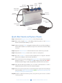
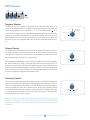
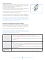
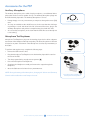
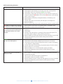
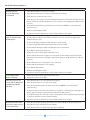
Tools for Schools
Platinum Sound Processor (PSP)
Product Guide
For Educators, Therapists, and Families
Platinum Series™ Sound Processor
The PSP is uniquely designed with children in mind. The PSP stands up to the challenge of
a child’s busy life, with a lightweight, pager-style design and a durable aluminum case for
greater protection. It offers an integrated headpiece and microphone, so nothing is worn
on small ears. This sound processor is universally compatible with all generations of
Advanced Bionics implants and sound processing strategies, including HiResolution®
Sound and Fidelity 120.
This guide provides information
on the features, accessories,
and use of the Platinum Sound
Processor. Should you need
support beyond this document,
please contact us at 877.829 .0026,
Monday through Friday, 5 a.m. to
5 p.m. PST, and ask to speak with
an audiologist, or you can visit
our website at www.BionicEar.com.
Volume
Sensitivity Control
Control
Headpiece
Cable Connector
Program
Selector
Built-in LED
Status Light
Processor
Electronics
Auxiliary
Input Jack
Headpiece
Cable
Rechargeable
Battery
Headpiece
Headpiece
Microphone
Quick-Start Guide and System Checks:
Step 1: Verify that the Program Selector/Switch is in the off position (O).
Step 2: Slide a fully charged Battery or AA Battery Pack into position on the Processor.
Check to ensure that the Battery is secure.
Step 3: Make sure that the Cable is plugged into both the Processor and the Headpiece.
Check that the Cable is not twisted or frayed. The connections should be stable,
not loose.
Step 4: Adjust the Volume Control so that the indicator notch is all the way to the left.
Step 5: Verify that the Sensitivity control notch is in the 12 o’clock position.
Step 6: Place the Headpiece over the internal implant (there is magnetic attraction
between the Headpiece and internal stimulator).
Step 7: Turn on the Processor by switching the Program Selector from off to the desired
program location (•, ••, •••). The LED (light emitting diode) will flash Red to
indicate PowerCel charge. A fully charged battery will flash three to four times.
Step 8: Verify that the LED stops flashing once successful communication or “lock” is
established between the Processor and internal implant.
Step 9: Slowly turn up the volume to the recommended position (based on the audiologist
or parent report). Note: The LED will flash green in response to loud sound, such
as a clap or voicing near the Microphone.
Step 10: Perform a behavioral listening check, using the Ling Six sounds or another
listening activity.
TOOLS for Schools by Advanced Bionics
2
platinum Sound Processor Product Guide
Microphone
Test Position
P2
Program 1 (P1)
OFF
PSP Features
Program
Selector
Volume
Sensitivity
LED Indicator
Auxiliary
Jack
Decrease
12:00
Increase
(On side of PSP.
Not shown.)
PSP control features
Program Selector
The PSP can store up to three (3) programs. In the Decrease
off position
(O), there is no
12:00 Increase
sound. As the Program Selector is rotated clockwise, the Processor is activated, and
one of three programs can be selected (•, ••, •••). The final position ( ) is reserved for a microphone test (see Troubleshooting/Microphone Test for more information). It is important that the team of individuals working with the child know
which programs are on the Processor and when to use these programs. When the
Processor is not in use, setting this dial to the off position will deactivate the Processor.
Program
Selector
Volume
Sensitivity
P3
P2
Microphone
Test Position
Program 1 (P1)
OFF
P3
Program
Selector
Microphone
P2
Test Position
Program 1 (P1)
OFF
LED Indicator
Volume Control
Auxiliary
The Volume Control allows the loudness level to be adjusted. Turning
the control in
Jack
(On side of PSP.
Not shown.)
a clockwise direction increasesProgram
the loudness; turning the control counterclockwise
LED Indicator
Selector Volume Sensitivity
decreases the loudness. The volume position is indicated by the raised line on the
dial, which typically is set to the 12 o’clock position.
Auxiliary
Jack
side of Although
PSP.
The audiologist has the ability to restrict or limit the Volume Control(Ondial.
Not shown.)
the dial will continue to work, a restricted range will limit the actual decrease or
increase to sound as the dial is moved. Programming the Volume Control in this
manner prevents accidental changes
Program in loudness (either too soft or too loud), which
LED Indicator
Selector Volume Sensitivity
could compromise the child’s hearing.
This is an important
feature to discuss with
the team of individuals supporting the child at school.
Auxiliary
Jack
Decrease
12:00
P3
P2
Increase
Microphone
Test Position
Program 1 (P1)
Decrease
OFF
12:00
Increase
Volume Control
Decrease
12:00
Increase
Decrease
Decrease
12:00
12:00
Increase
Increase
Decrease
12:00
Increase
(On side of PSP.
Not shown.)
Sensitivity Control
The Sensitivity Control determines the quietest level of sound that will be picked up
from the environment by the Microphone. The dial is typically set between 11 and 12
o’clock. Turning the Sensitivity Control in a clockwise direction increases the Microphone’s sensitivity for softer, more distant sounds. Turning the Sensitivity Control
counterclockwise decreases the sensitivity so that softer and more distant sounds are
not picked up by the Microphone. This may help in the presence of background
noise, for example in a cafeteria or gym.
Sensitivy Control
Note: Increasing the Sensitivity (clockwise) beyond the 12:00 position will increase
the Green LED response. Conversely, decreasing the Sensitivity (counterclockwise)
will decrease the response and require louder sounds to be present in order to activate
this feature.
TOOLS for Schools by Advanced Bionics
3
platinum Sound Processor Product Guide
Auxiliary Input Jack
The Auxiliary Input Jack, located on the side of the Processor, can be used to connect
external auditory input sources, such as an FM System. There are several points to
consider in connecting an audio device to the Sound Processor:
1. An interface cable may be required.
2. The PSP must contain a program set up for auxiliary input (see Audio-Mixing).
Consult the audiologist or family regarding the program settings.
3. Only battery-powered devices should be plugged into the Sound Processor,
unless a patch cable with special electronics is used.
Auxiliary Input Jack
Advanced Bionics Customer Service is available to discuss questions regarding connecting to external auditory devices and the equipment needed, at 1.877.829.0026.
NOTE: The Auxiliary Input Jack on the PSP is 3.5 mm in size and was designed for
mono input. Plugging a stereo device (like and iPod or FM System) into the mono jack
may degrade the sound quality. A stereo-to-mono adapter will allow connection of
these devices and is available at most electronics stores.
Dual-Color LED (Light Emitting Diode) Indicator
The PSP is equipped with a built-in LED Status Indicator. The LED is a diagnostic
light that provides parents and teachers with information regarding Processor
function. It is located next to the Headpiece Jack and becomes active when the
Processor is turned on. The chart below describes the LED functions.
Note: Under very rare conditions, the programming audiologist may have set the
Processor so that the Green LED may not illuminate. Check with the programming
audiologist to see if this feature has been de-activated.
Battery Charge Status
When the Processor is first turned on, the LED will indicate the following:
• Three (3) to four (4) quick RED blinks indicate the battery is fully charged.
• Two (2) quick RED blinks indicate the battery is sufficiently charged to power the system.
• One (1) quick RED blink indicates that the battery charge is nearly depleted. The battery should
be replaced.
Lock Status
• Refers to the successful communication between the external device (Headpiece) and internal
device.
• After the battery charge status is complete, the RED LED will continue to flash, approximately
once per second, until the Headpiece is properly positioned over the implant and successful
communication is established.
• If the device is not transmitting sound to the implant, such as when the Headpiece falls off, the
LED will flash RED.
Microphone/System
Status
• Once the battery and lock status LED sequences are complete, the LED should flash GREEN in
response to your speech patterns as you talk closely into the Headpiece Microphone.
TOOLS for Schools by Advanced Bionics
4
platinum Sound Processor Product Guide
Audible Alarm
The Audible Alarm is a programmable feature and is program specific. The Alarm
is designed primarily for children, in order to alert parents and teachers when the
device needs attention. Once the problem has been rectified, the PSP will resume
normal function.
The Alarm will emit a slow beeping tone, and the LED will flash RED if any of the
following occur:
1. Headpiece falls off.
2. A communication problem between the Processor and implant (loss of lock).
If the battery is near depletion, the alarm will emit a slow beeping tone until the
battery dies or is replaced.
Platinum Headpiece & Cable
The Platinum Headpiece integrates the Microphone and transmitter for sending
sound information to the implant. The Microphone is located behind the opening
in the color cap. There are two types of Headpieces: The curved bottom style is
provided for the 90K implant, which is the most current technology. Children with
implants placed before 2003 (CII Bionic Ear, Clarion 1.0 and 1.2) will utilize a flatbottom Headpiece. The audiologist or family will know which type of implant is in use.
There is a magnet housed within the Headpiece, which is designed for the implant
system. This magnet will attract the internal stimulator magnet under the skin.
Placing the Headpiece over the implant area should result in sufficient attraction to
hold the system in place and allow the Processor and implant to communicate.
The strength of the magnet is determined by the audiologist and should not be
changed without a consultation. If Headpiece retention is a problem, or irritation/
skin redness is noted, the programming center should be notified immediately.
The Cable connects the Headpiece to the Processor. It is the pathway for relaying
information between the external and internal implant components. Cables are
available in multiple lengths and in two colors: beige or brown. At one end of the
Cable is a two-prong plug, which is inserted into the Headpiece. The pins are of
different diameters and must be correctly inserted. A small coaxial plug is located
at the other end of the Cable and connects to the Headpiece jack of the Processor.
Removing and replacing the Cable continuously will weaken the connection, so
only remove the Cable when it needs to be replaced.
TOOLS for Schools by Advanced Bionics
5
Platinum Headpieces
Platinum Headpiece Cable
NOTE: Be sure to turn off the
Processor before removing the
Cable from the Headpiece.
NOTE: Make sure that no debris is
blocking the microphone opening
on the Headpiece.
platinum Sound Processor Product Guide
Power Options
A custom-designed, rechargeable lithium-ion battery powers the Processor. The battery slides on and is held in place by a latch. As an alternative to the rechargeable
batteries, a AA Battery Compartment can be used. The AA Battery Compartment
uses three (3) AA batteries.
How to Replace the Rechargeable Battery or Battery Pack
1.Depress the small latch on the side of the PSP in an upward motion.
Rechargeable Lithium-ion Battery
2. At the same time, gently slide the battery off of the Processor tracks.
3.A newly charged battery can then be placed on the tracks, sliding until the
latch clicks into place—the battery is now secure.
Note: The battery contacts should be gently cleaned at least once a month with a
clean cotton swab or a hearing-aid brush.
Note: Educators/therapists may want to keep on hand the AA Battery Pack as a
backup power source in case additional rechargeable batteries are not available.
AA Battery Pack
Audio-Mixing
Audio-Mixing refers to the amplification ratio between the Headpiece Microphone
and an auxiliary input device. Audio-Mixing allows the child’s Headpiece Microphone to remain on when connected to an auxiliary input, such as an FM System or
iPod. This allows the child to hear his own voice and sounds around him in addition
to the input from the auxiliary device. The Audio-Mixing is set for each program on
the Sound Processor by the audiologist during programming. The default AudioMixing recommendation is 50/50. For a description of the Audio-Mixing options,
refer to the table below.
Audio-Mixing Options Processor Microphone Auxiliary Input (i.e. FM System)
Mic Only
On
Off
50/50 - Mic/Aux*
On
On
30/70 - Mic/Aux**
On (-10dB)
On
Aux Only (Atten.)
Off
On (-20dB)
Aux Only
Off
On
*For classroom use and the default programming setting
**For noisy environments where greater input is needed from the FM (i.e., theatre,
church, noisy restaurant, etc.)
TOOLS for Schools by Advanced Bionics
6
platinum Sound Processor Product Guide
Accessories for the PSP
Auxiliary Microphone
The Auxiliary Microphone, also called a lapel microphone, is an additional Microphone that can be used in a number of ways. The Auxiliary Microphone plugs into
the PSP’s Auxiliary Input Jack. The Auxiliary Microphone is for use:
• During therapy or in noisy environments, as it improves the signal-to-noise (S/N)
ratio.
Auxiliary Microphone
• As a way to troubleshoot the child’s Processor. In the event that the child stops
responding to sound with what looks like a functional Processor, plug in the
Auxiliary Microphone and perform a simple listening check with the child.
• As a secondary microphone, in the event that the child’s Processor Microphone
is not working.
Microphone Test Earphones
Microphone Test Earphones plug into the Auxiliary Input Jack to allow subjective
assessment of the Headpiece Microphone quality. This allows the parent or educator
to listen for any static or distortion in the Microphone as well as any intermittency in
the Cable.
To perform a Microphone test, complete the following steps:
• Remove the PSP from the child.
Microphone Test Earphones
• Plug the Microphone Test Earphones into the Auxiliary Input Jack located on
the side of the PSP.
• Turn the program dial to microphone test position ( ).
• Put on the Microphone Test Earphones.
• Speak into the Headpiece normally and monitor the output through the
Earphones.
• Move the Cable around to listen for any intermittencies.
Note: During the testing of the Microphone, changing the Volume and Sensitivity
Controls will not affect the overall output of sound.
TOOLS for Schools by Advanced Bionics
7
PSP with Headpiece, Cable, and
Michrophone Test Earphones
platinum Sound Processor Product Guide
System Sensor
The System Sensor is for use with the Auria, Platinum BTE/CII BTE, PSP, and S-Series
Sound Processors. It is a handheld device that performs a system functionality check.
The System Sensor is powered by a lithium battery and will need to be replaced
approximately every two years.
System Sensor
To Use:
Place the Sensor over the Headpiece at a distance of approximately one (1) to two
(2) inches, then gently press the button. The Sensor will display its status.
• Orange light indicates that the System Sensor itself is functioning properly.
• No Orange light indicates that the System Sensor battery is depleted. You will
need to obtain a new System Sensor.
Once you have verified the Sensor status (Orange light), slowly move the Sensor
toward the Headpiece and observe the system-transmitting status as follows:
• Solid green light means that the system is functioning properly.
• Flashing green light means that the Processor is not communicating with the
implant. The Processor battery is charged, but the system is not successfully
transmitting a signal to the implant. Stop and proceed to Troubleshooting.
• No green light indicates that the Processor battery is discharged and needs to
be changed.
PSP Troubleshooting
If you notice a problem with your child’s implant, take the following steps before
proceeding to the Troubleshooting chart below:
• Make sure the child’s Processor is set to his/her user settings.
• Verify that the Processor is on.
• Verify that the Volume and Sensitivity controls in the correct position.
• Visually inspect the child’s equipment.
• Verify that the battery is in place and the LED flashes green with voicing into
the Microphone.
• Visually inspect the Cable for any signs of twisting, fraying, or breaks.
• Check the Headpiece for damage.
• Check battery status and/or replace battery.
TOOLS for Schools by Advanced Bionics
8
platinum Sound Processor Product Guide
PSP Troubleshooting Situations:
Problem
Action
Child cannot hear
1. Make sure PSP is on.
2. Check Volume and Sensitivity to ensure they are in the correct positions.
3. Check LED to make sure it is flashing green to loud input.
4. Check battery charge status by turning the processor off and on again and
noting the number of RED flashes. Three to four RED flashes means that the
battery is fully charged.
5. Replace battery with backup rechargeable battery or AA battery pack.
6. Replace Cable.
7. Check the Microphone functionality with Microphone Test Earphones.
8. Replace Headpiece.
9. Contact programming center and/or child’s parent for further troubleshooting.
Red LED is not blinking when the PSP is 1. Replace battery with another rechargeable battery or AA battery pack.
first turned on or there is only one blink 2. Clean battery contacts with an alcohol swab.
Red LED continuously blinks at onesecond intervals and/or Audible Alarm
(if activated) sounds at one second
intervals
1. Make sure the Headpiece is on the child’s head and positioned over the
implant site.
2. Check Cable.
3. Determine if the Microphone is working by following the Microphone Test
Procedures. (Refer to page 7 of this guide for instructions.)
4. Replace Headpiece if during the Microphone Test the Microphone seems faulty.
5. Contact the programming center and/or child’s parent for further
troubleshooting.
Green LED does not illuminate to loud 1. Make sure PSP is on and set to a program.
speech close to Microphone
2. Check Volume and Sensitivity settings to ensure they are set correctly.
3. Check battery status by turning off the PSP and then on again. If the battery
is near depletion, change battery.
4. Check the Microphone functionality, using the Microphone Test Procedures.
5. Replace Cable if no sound heard.
6. Replace Headpiece if no sound heard after replacing the Cable.
7. Contact the programming center and/or the child’s parent for further
troubleshooting.
Child reports hearing sounds that are
distorted or static
1.
2.
3.
4.
5.
6.
Ensure Cable is not damaged (kinked or frayed) and inserted into the PSP.
Try alternative program.
Listen for static with the Microphone Test Earphones.
Verify that the cable is not twisted or frayed.
Replace Headpiece if static is heard and cable appears to be in good condition.
Contact the programming center and/or the child’s parent for further
troubleshooting.
TOOLS for Schools by Advanced Bionics
9
platinum Sound Processor Product Guide
Using Personal FM Systems with the PSP
What is an FM System?
An FM (Frequency Modulated) system is a wireless communication technology
commonly used in the classroom to overcome the adverse effects of distance and
competing noise.
Connecting the Child’s PSP to an FM System:
1. Ensure that you have obtained the appropriate FM Adapter Cable to use with
the FM System. If you are not sure please contact the FM manufacturer.
2. Ensure that the FM System is functioning appropriately by listening to the FM
System through an amplified speaker or Walkman-style earphones.
3. Keeping the FM System and Sound Processor in the “off” position, connect the
Sound Processor and FM receiver through the Auxiliary Input Jack via the
adapter cable.
4. Set any gain, output, or tone controls on the FM receiver per the child’s
audiologist or FM manufacturer’s recommendations (as applicable).
1. MLxS Receiver
2. Microlink CI-S Adapter,
and 3. Adapter Cable
5. Ensure that the volume on the FM receiver and the Volume and Sensitivity
Controls on the PSP are both set to the minimum level.
6. Turn on the transmitter, receiver, and Sound Processor in that order.
Note: It is important that you turn on the equipment in the proper order to
prevent the child from hearing any adverse sound percepts.
7. Gradually increase the Volume and Sensitivity on the student’s Sound Processor
to their everyday settings or as specified by the child’s audiologist.
8. Gradually increase the volume on the FM receiver to a comfortable listening
level or as specified by child’s audiologist or the FM manufacturer.
9.Complete a functional listening check:
•Administer a listening task that you know the user can perform at 100%,
such as the Ling Six Sound Test and/or common phrases.
•Perform these listening tasks in an auditory-only condition and in close
proximity to the child. Repeat the task at a distance of several meters, noting
that no changes in performance are observed with the FM in quiet.
•The functional listening check can also be repeated in noise to assess the
effects of the cochlear implant + FM.
Tips to Reduce Interference:
1. Ensure that the FM Adapter Cable does not wind around the Headpiece Cable.
2. Ensure that the transmission range is not exceeded. The broadcast range
between FM transmitters and receivers may begin to break up at distances
greater than 40 feet indoors and 120 feet outdoors.
3.Observe areas in the classroom, or other environments, that can cause “dead
spots” in transmission. Complete a listening check with the FM System in the
classroom to listen for any problem areas and avoid seating the child in these
problem areas.
TOOLS for Schools by Advanced Bionics
10
platinum Sound Processor Product Guide
Troubleshooting the FM System and Cochlear Implant
Keep in mind that you are working with two separate systems, an FM System and a
cochlear implant Sound Processor. The best way to complete troubleshooting is to
begin by separating the two systems and troubleshoot them separately.
Troubleshooting the FM System:
1.Disconnect the FM System from the child’s Sound Processor
2. Verify the FM System is working by listening to the FM System. To do this, plug
the FM receiver into a small speaker (RadioShack) or a Headset FM checker and
verify that the signal is being received and is clear.
3. If the FM System is not working, complete troubleshooting for the FM System as
recommended by the FM manufacturer. Ask the following questions:
• Are the FM transmitter and receiver on the same channel?
• Are the cables on the FM transmitter or receiver frayed or kinked?
• Has the transmitting distance been exceeded?
• Do the batteries for the FM transmitter and/or receiver need to be replaced?
• Is the microphone on the transmitter working?
• Are the FM settings set appropriately?
Troubleshooting the Sound Processor:
1. Can the child hear clearly with the cochlear implant alone?
2. If the child cannot hear with the cochlear implant alone, complete troubleshooting
for the Sound Processor as directed by the PSP Troubleshooting Situations listed
previously in this document.
TOOLS for Schools by Advanced Bionics
11
platinum Sound Processor Product Guide
FM Troubleshooting Situations:
Problem
Action
Child cannot hear
when the FM System
is connected
1. Verify that the PSP is on and at user settings.
2. Verify that the FM System is working, check battery and settings.
3. Verify that your connections are secure.
4. Verify that you are using the proper FM Adapter Cable for the FM System and PSP (Contact
Advanced Bionics and FM manufacturer if you are unsure if the appropriate adapter cable
is in use).
5. Verify that the Audio-Mixing ratio has been set for FM use (50/50 is recommended for
classroom use).
6. Replace the FM Adapter Cable.
7. If problem cannot be determined, contact Advanced Bionics for support.
Child reports noise,
static, or distortion with
the FM System
1. Verify that you are using the proper FM Adapter Cable for the FM System and PSP.
(Contact Advanced Bionics and FM manufacturer if you are unsure if the appropriate
adapter cable is in use).
2. Ensure the Headpiece Cable and FM cable are not intertwined.
3. Increase the physical distance between the FM receiver and PSP.
4. Ensure that the Headpiece Cable and FM cable are not intertwined.
5. Try a different transmitting frequency.
6. Reduce the volume and/or gain on the FM receiver.
7. Ensure that the transmission range is not exceeded—the broadcast range between FM
transmitters and receivers may begin to break up at distances of 40 feet indoors; 120 feet
outdoors.
8. Ensure that there are no “dead spots” in the classroom.
9. Ensure that the transmitter is worn properly.
10. Try a different FM channel.
11. Replace the FM Adapter Cable.
12. If problem cannot be determined, contact Advanced Bionics for support.
Green LED on PSP
flashes constantly
Listening responses are
poorer with the FM System
and PSP than with the
PSP alone
1. Reduce the volume and/or gain on the FM receiver.
2. Reduce the volume on the PSP.
1. Verify that the PSP is set to the appropriate program.
2. Verify the PSP volume is set to the user settings.
3. Verify the Audio-Mixing ratio has been set for FM use (50/50 is recommended for
classroom use).
4. Increase the gain on the FM receiver (this may need to be completed by the audiologist as
there is special software to adjust the parameters of the FM receiver).
5. Try a 30/70 mixing ratio. You may need to consult with the child’s programming audiologist
or parent to determine current program settings.
6. If problem cannot be determined, contact Advanced Bionics for support.
Child cannot hear his/her
own voice or other’s voices
in the environment
1. Verify the Audio-Mixing setting (should be set to either a 50/50 or 30/70 mixing ratio).
2. Verify the Processor and FM are at user settings.
3. Verify that the child isn’t experiencing any other complaints.
TOOLS for Schools by Advanced Bionics
12
platinum Sound Processor Product Guide
FM Manufacturer Resource Information
Oticon
Oticon, Inc.
29 Schoolhouse Rd
Somerset, NJ 08873
Fax: 732.560.0029
[email protected]
www.oticonusa.com
Phonak Inc, US
Phone: 800.679.4871 • 630.821.5000
[email protected]
www.phonak-us.com
Advanced Bionics®
Phone: 877.829.0026
TTY: 800.678.3575
Monday – Friday 5 a.m. to 5 p.m. PST
[email protected]
www.BionicEar.com
TOOLS for Schools by Advanced Bionics
13
platinum Sound Processor Product Guide
Headquarters
Advanced Bionics, LLC
12740 San Fernando Road
Sylmar, CA 91342 USA
877.829.0026 in USA and Canada
800.678.3575 TTY
661.362.1400
661.362.1500 Fax
[email protected]
Europe
Advanced Bionics SARL
76 rue de Battenheim
68170 Rixheim, France
+33.3.89.65.98.00
+33.3.89.65.50.05 Fax
[email protected]
Asia-Pacific
Advanced Bionics Asia-Pacific Limited
Suite 4203, 42/F, Tower One
Lippo Centre, 89 Queensway
Hong Kong
852.2526.7668
852.2526.7628 Fax
[email protected]
Latin America
Advanced Bionics
28515 Westinghouse Place
Valencia, CA 91355 USA
661.362.1840
661.362.4604 Fax
[email protected]
www.BionicEar.com/TFS
Tools for Schools is a free program designed by Advanced Bionics to help children with cochlear implants
succeed in the classroom. The program provides education, support, and tools to educators, therapists, and families!
SEPT09_3-01066-E-3
©2009 Advanced Bionics, LLC. All rights reserved.