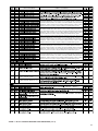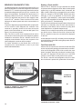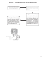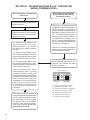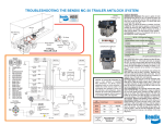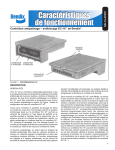
1
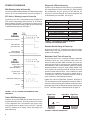
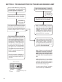
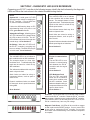
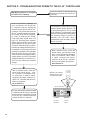
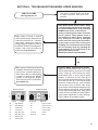
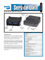
ABS PARTIAL SHUTDOWN
Reading a Fault
Depending which component the fault is detected on, the
ABS and ATC functions may be fully or partially disabled.
Even with the ABS warning lamp on, the EC-30™ controller
may still provide ABS function on wheels that are not
affected by the fault. The EC-30™ controller should be
serviced as soon as possible.
When a fault is detected, the EC-30™ controller identifies
the faulted component with the diagnostic LEDs. When
a wheel speed sensor fault, or an ABS modulator fault is
detected, the SEN or MOD LED will be accompanied by two
location LEDs. An example is FRT-RHT-SEN. When these
three LEDs are on, this is an indication of a fault on the front
axle(FRT), right side(RHT), wheel speed sensor(SEN).
For a complete explanation and troubleshooting of faults
displayed by the LEDs, go to section F, Troubleshooting.
Front ABS Modulator Fault
ABS on the affected wheel is disabled. ABS and ATC on
all other wheels remains active.
Rear ABS Modulator Fault
ATC is disabled. ABS on the affected wheel is disabled.
ABS on all other wheels remains active.
Front Wheel Speed Sensor Fault
The faulted wheel is still controlled by using input from
the remaining wheel speed sensor on the front axle. ABS
remains active on the rear wheels. ATC is disabled.
Mid or Rear Wheel Speed Sensor Fault
ATC is disabled. In a four sensor system, ABS on the
affected wheel is disabled, but ABS on all other wheels
remains active.
In a six sensor system, ABS remains active by using input
from the remaining rear wheel speed sensor on the same
side.
ATC Modulator Fault
The red diagnostic LEDs only indicate active system faults.
When a fault self-heals or is manually reset, the fault code
remains in fault history. Fault history can be retrieved by
using blink code diagnostics or a diagnostic tool.
If faults occur on multiple components, the diagnostic
LEDs will display one fault at a time. When the first fault is
repaired and the EC-30™ controller is reset, the next fault
will be displayed on the LEDs.
Fault Reset
After the fault is corrected, the active fault code and LEDs
can be reset by briefly holding a magnet in place at the
RESET location of the diagnostic display. All of the LEDs
will be on while the magnet is held in place. If one or more
LEDs do not go on when the magnet is in place, replace the
EC-30™ controller. When the magnet is removed from the
reset location, only the green VLT diagnostic LED should
remain on. If red LEDs are still on, active faults are still
present in the system.
Note: An EC-30™ controller self-configuration will occur if
a magnet is held at the reset location for greater than 20
seconds.
ATC is disabled. ABS remains active.
J1939/J1922 Communication Fault
ATC is disabled. ABS remains active.
ECU Fault
ABS and ATC are disabled. The system reverts to normal
braking.
Voltage Fault
Front Axle
Mid Axle
Magnetic
Reset Switch
Rear Axle
While voltage is out of range, ABS and ATC are disabled.
The system reverts to normal braking. When the correct
voltage level is restored, full ABS and ATC function is
available. Operating voltage range is 9.0 to 16.0 VDC.
EC-30™ CONTROLLER DIAGNOSTIC DISPLAY
The EC-30™ controller diagnostic display consists of nine
red fault LEDs, one green power LED and an internal,
magnetic reset switch. See figure 9 for illustration.
Right Side
Left Side
ATC
Modulator
Sensor
™
No tools are needed to read the EC-30 controller
diagnostic display. A fault displayed on the LEDs will always
be accompanied by the illumination of the ABS warning
lamp and/or the ATC active/warning lamp.
ECU
Voltage
FIGURE 9 - EC-30™ CONTROLLER LED DIAGNOSTIC
DISPLAY
9