1
Administrator Operations Guide
1
What You Can Do with Remote Communication Gate S
2
Login and Logout
3
Settings
4
Printer Management
5
Log Management
6
Firmware Management
7
Installation Support
8
Maintenance of Remote Communication Gate S Server
9
Authentication Management
10
Other Management
11 Appendix
Read this manual carefully before you use this product and keep it handy for future reference.
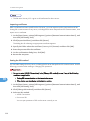
How to Read This Manual
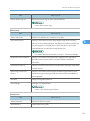
Symbols
The following set of symbols is used in this manual.
Indicates a situation that may result in property damage or malfunction if instructions are not followed. Be
sure to read the instructions.
Indicates information or preparations required prior to operating.
Indicates a function's limitations.
Indicates supplementary relevant information.
Indicates where you can find further relevant information.
[]
Indicates the names of keys that appear on the computer screen.
Terminology
The following is an explanation of the terminology used in this manual:
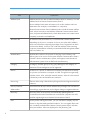
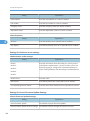
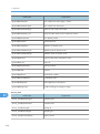
Term
Access log
Explanation
Access logs are records of access results for devices registered in the Remote
Communication Gate S server. They record login, logout, and setting
events.
1
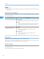
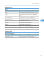
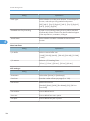
Term
Address Book
Explanation
"Address Book" can refer to either the address book on a device, or to the
address books in Remote Communication Gate S.
Device address books store information such as fax numbers and scan
destinations (for example, e-mail address or computers).
Remote Communication Gate S address books include the master address
book, which stores the e-mail address of Remote Communication Gate S
users, and personal address books, which administrators can create to store
frequently accessed e-mail addresses.
2
Allocation file
An allocation file (UserTable.csv) is a CSV file that contains settings
depending on the user or computer such as a user code and IP address,
and is one of the files comprising a package. Even if a general user does
not know the details, such as a user code and address of the executing
computer, the installation will easily succeed with this file having been edited
with a text editor, etc.
Authentication
Authentication refers to the process of verifying a user's identity, and
allowing him or her access to the system. Remote Communication Gate S
includes a built-in authentication system, and supports several external
authentication systems such as LDAP and ActiveDirectory.
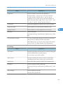
Category
A category classifies groups. Every group belongs to one category. A
maximum of three categories can be registered.
Device
A "device" is a printer or multifunction machine connected to the network
or a printer connected to a computer via USB. Though the term generally
includes routers, hubs, and other network devices, "device" in this manual
is limited to printers and multifunction machines.
Device Log
The term "device log" refers both to job logs and access logs retrieved from
a device.
Device/Network
Administrator
Users that have device/network administrator privileges can view device
lists and logs, register devices, and configure settings on registered devices.
Discovery
Discovery refers to the process of automatically detecting devices
connected to the network and devices connected to computers via USB,
and then registering them to Remote Communication Gate S.
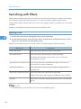
Filter
On the printer and log list screens, you can use filters to display only the
printers or logs that meet specified conditions. You can register filters with
new conditions and edit filters. Remote Communication Gate S includes
some pre-set filters. Filters are displayed on the [Directory] tab.
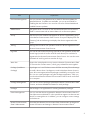
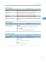
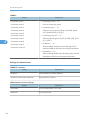
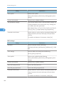
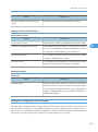
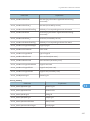
Term
Explanation
Firmware Management
You can connect to the global server to check for firmware updates for
specified devices. If updates are available, you can set a schedule for
installing the new firmware. You can also view a list of downloaded and
installed firmware updates.
Global Server
The global server is a server on the Internet that Remote Communication
Gate S communicates with to retrieve data such as firmware updates.
Group
The Group function enables management of devices registered by group
in the Remote Communication Gate S server. Groups are displayed on the
[Directory] tab and selecting one displays the devices registered in that
group.
Job log
Job logs are records of user operation results for devices registered in the
Remote Communication Gate S server.
Log Data
You can list and confirm the job logs (records of user operation results) and
access logs (records of access results for each device) for each device
registered in the Remote Communication Gate S server. You can also view
the details of each log and run searches for logs.
Menu bar
A menu bar is displayed on many screens in Remote Communication Gate
S. The menu bar contains menus, which group related functions together.
Package (Installation
Package)
A package is an ".exe" file that contains all of the necessary files and settings
to install a device driver. Packages are used to distribute device drivers to
users. All content registered with a package is installed by running the ".exe"
file. You can create packages using the Packager application, which you
can download from the Remote Communication Gate S server and install
on a computer.
Package Management
You can view a list of packages uploaded to Remote Communication Gate
S server, and view detailed information for each package.
Packager
The Packager is an application for creating installation packages.
Printer Management
You can view the devices registered to Remote Communication Gate S to
check their status and details. It is also possible to register new devices and
search for existing devices. In addition, you can configure various settings
on the devices.
Remote Communication
Gate S Administrator
Users that have Remote Communication Gate S administrator privileges can
access all functions and settings in Remote Communication Gate S.
3
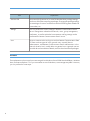
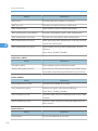
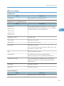
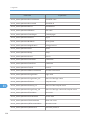
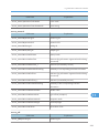
Term
Explanation
Scenario file
A scenario file (Scenario.ini) is a text file that describes package settings,
and is one of the files comprising a package. Changing the package settings
or extending its functions can be done with this file having been edited with
a text editor, etc.
Settings
You can perform the various settings in Remote Communication Gate S
server. Setting Menu related to the network, views, group management,
notification, as well as individual customization and log settings can be
performed for Remote Communication Gate S server.
User
A user is someone who can log in to and use Remote Communication Gate
S. There are three types of users: general users, network/device
administrators, and Remote Communication Gate S administrators. In this
manual, the term "user" usually refers to a general user. A general user can
view the device list and device details, and can download install packages.
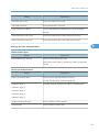
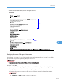
Screens
The explanations in this manual use screen images from Windows Server 2008 Standard Edition, Windows
Vista, and Internet Explorer 7.0. If you use another version of Windows, screen images may differ. However,
you can perform the same steps.
4
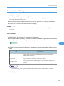
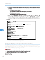
Guides for This Solution
The following guides are available for Remote Communication Gate S:
Remote Communication Gate S Administrator Operations Guide (this manual, HTML/PDF)
This guide is intended for the administrator. It explains how to utilize Remote Communication Gate
S to configure and manage settings and operations: for example, registration and monitoring of
devices, the creation of installation packages, or retrieval of device logs.
Remote Communication Gate S Installation Guide (HTML/PDF)
This guide is intended for the administrator and explains the installation, uninstallation, and quick setup
procedures for Remote Communication Gate S.
Remote Communication Gate S User's Guide (HTML/PDF)
This guide is intended for the end user. It explains how to display devices, search for devices, and
install packages by logging in Remote Communication Gate S.
• Acrobat Reader or Adobe Reader is required to view the PDF documentation.
• You can view the HTML documentation using a Web browser. We recommend Microsoft Internet
Explorer 4.01 SP2 or a later version.
• A simplified version of the HTML documentation is available for earlier or non-recommended
browsers.
• If JavaScript is disabled or unavailable in your browser, you will not be able to search or use certain
buttons in the HTML documentation.
• If you are using an earlier or non-recommended browser and the simplified version of the
documentation does not appear automatically, replace \int\index_book.htm with \unv
\index_book.htm in your browser's address bar.
5
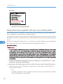
Important
• TO THE MAXIMUM EXTENT PERMITTED BY APPLICABLE LAW:
• THE SUPPLIER SHALL NOT BE LIABLE FOR THE RESULT OF OPERATION OF THIS SOFTWARE
OR THE USE OF THIS DOCUMENT.
• THE SUPPLIER SHALL NOT BE LIABLE TO YOU FOR DAMAGES OR LOSS OF ANY
DOCUMENT OR DATA PRODUCED BY USING THIS SOFTWARE.
• THE SUPPLIER SHALL NOT BE LIABLE TO YOU FOR ANY CONSEQUENTIAL, INCIDENTAL
OR INDIRECT DAMAGES (INCLUDING, BUT NOT LIMITED TO, DAMAGES FOR LOSS OF
PROFITS, BUSINESS INTERRUPTION OR LOSS OF BUSINESS INFORMATION, AND THE
LIKE) CAUSED BY FAILURE OF THIS SOFTWARE OR LOSS OF DOCUMENTS OR DATA, NOR
FOR ANY OTHER DAMAGES ARISING OUT OF THE USE OF THIS SOFTWARE, IF THE
SUPPLIER HAS BEEN ADVISED OF THE POSSIBILITY OF SUCH DAMAGES.
• Some illustrations or explanations in this guide may differ from your product due to improvement or
change in the product.
• The contents of this document are subject to change without notice.
• No part of this document may be duplicated, replicated, reproduced in any form, modified or quoted
without prior consent of the supplier.
• It is possible that any document or data stored in the computer will be damaged or lost by user error
during operation or software error. Be sure to back up all important data beforehand. Important
documents and data should always be copied or backed up. Documents and data can be lost because
of malfunction or human error. Furthermore, the customer is responsible for protection measures
against computer viruses, worms, and other harmful software.
• Do not remove or insert any disk while operating this software.
6
Trademarks
Adobe®, Acrobat®, Acrobat Reader®, and Flash® are either registered trademarks or trademarks of
Adobe Systems Incorporated in the United States and/or other countries.
Microsoft®, Windows®, Windows Server®, Windows Vista®, Internet Explorer®, and SQL Server® are
either registered trademarks or trademarks of Microsoft Corporation in the United States and/or other
countries.
Pentium® is a registered trademark of Intel Corporation.
Apache Tomcat is a trademark of the Apache Software Foundation.
Novell® is a registered trademark of Novell, Inc. in the United States.
Notes® is a registered trademark of IBM Corporation and Lotus Development Corporation.
Other product names used herein are for identification purposes only and might be trademarks of their
respective companies. We disclaim any and all rights to those marks.
This product includes software developed by the OpenSSL Project for use in the OpenSSL Toolkit.
(http://www.openssl.org/)
The proper names of the Windows operating systems are as follows:
• The product names of Windows 2000 are as follows:
Microsoft® Windows® 2000 Professional
Microsoft® Windows® 2000 Server
Microsoft® Windows® 2000 Advanced Server
• The product names of Windows XP are as follows:
Microsoft® Windows® XP Home Edition
Microsoft® Windows® XP Professional
• The product names of Windows Vista are as follows:
Microsoft® Windows Vista® Ultimate
Microsoft® Windows Vista® Enterprise
Microsoft® Windows Vista® Business
Microsoft® Windows Vista® Home Premium
Microsoft® Windows Vista® Home Basic
• The product names of Windows 7 are as follows:
Microsoft® Windows® 7 Home Premium
Microsoft® Windows® 7 Professional
Microsoft® Windows® 7 Ultimate
• The product names of Windows Server 2003 are as follows:
7
Microsoft® Windows Server® 2003 Standard Edition
Microsoft® Windows Server® 2003 Enterprise Edition
• The product names of Windows Server 2003 R2 are as follows:
Microsoft® Windows Server® 2003 R2 Standard Edition
Microsoft® Windows Server® 2003 R2 Enterprise Edition
• The product names of Windows Server 2008 are as follows:
Microsoft® Windows Server® 2008 Standard
Microsoft® Windows Server® 2008 Enterprise
• The product names of Windows Server 2008 R2 are as follows:
Microsoft® Windows Server® 2008 R2 Standard
Microsoft® Windows Server® 2008 R2 Enterprise
8
TABLE OF CONTENTS
How to Read This Manual.................................................................................................................................1
Symbols...........................................................................................................................................................1
Terminology....................................................................................................................................................1
Screens............................................................................................................................................................4
Guides for This Solution.....................................................................................................................................5
Important.............................................................................................................................................................6
Trademarks..........................................................................................................................................................7
1. What You Can Do with Remote Communication Gate S
Remote Communication Gate S Editions........................................................................................................19
Product Edition Naming Conventions........................................................................................................19
Overview of Remote Communication Gate S Pro for @Remote Enterprise.............................................20
Overview of Remote Communication Gate S Pro with Remote Communication Gate S Pro @Remote
Connector.....................................................................................................................................................21
Network Device Monitoring............................................................................................................................22
Device Counter Management.........................................................................................................................27
Device Address Book Management...............................................................................................................29
Printer Driver Distribution to Users...................................................................................................................30
Firmware Updates............................................................................................................................................33
Batch Configuration of Device Settings..........................................................................................................35
Device Log Management................................................................................................................................36
Printer Maintenance with @Remote Service...................................................................................................38
2. Login and Logout
Access...............................................................................................................................................................41
Access from Server Computer's Start Menu..............................................................................................41
Access from Web Browser..........................................................................................................................41
Login..................................................................................................................................................................43
Top Page......................................................................................................................................................43
Navigating the Remote Communication Gate S Screens.........................................................................46
Logout................................................................................................................................................................50
3. Settings
Initial Settings Wizard......................................................................................................................................51
Accessing the Initial Settings Wizard.........................................................................................................51
Group Initial Settings...................................................................................................................................52
9
HTTP Proxy Initial Settings...........................................................................................................................53
Email Initial Settings.....................................................................................................................................54
Device Polling Initial Settings......................................................................................................................54
Initial Discovery Settings..............................................................................................................................55
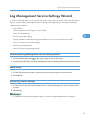
Log Management Service Settings Wizard...................................................................................................57
Accessing the Log Management Service Settings Wizard.......................................................................57
Select device................................................................................................................................................57
Device Log Transfer Settings.......................................................................................................................57
Specify Log Storage Period........................................................................................................................58
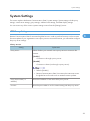
System Settings.................................................................................................................................................59
HTTP Proxy Settings.....................................................................................................................................59
Email Settings...............................................................................................................................................60
Category Settings........................................................................................................................................61
Personal Address Book Settings.................................................................................................................67
Select Date Display Format.........................................................................................................................68
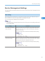
Device Management Settings.........................................................................................................................69
Status Polling................................................................................................................................................69
Discovery Settings........................................................................................................................................71
Log Management Service Settings.............................................................................................................80
User Counter Collection Schedule Settings...............................................................................................82
Filter Settings.................................................................................................................................................83
Counter Information Notification Settings..................................................................................................84
Customized Display Settings...........................................................................................................................87
Printer Management List Display Settings..................................................................................................87
System Log List Display Settings..................................................................................................................87
Job Log List Display Settings........................................................................................................................88
Access Log List Display Settings..................................................................................................................92
Display Item Settings for Client Users.........................................................................................................96
Firmware Management List Display Settings.............................................................................................97
Package Management List Display Settings..............................................................................................97
User Properties Column Name Settings.....................................................................................................98
User Account List Display Settings..............................................................................................................98
Service Information........................................................................................................................................100
10
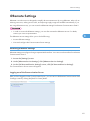
@Remote Settings...........................................................................................................................................101
Accessing @Remote Settings....................................................................................................................101
Viewing and Configuring Communication Server Settings....................................................................102
Site Map Settings...........................................................................................................................................111
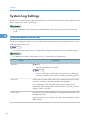
System Log Settings.......................................................................................................................................112
Printer Management System Logs............................................................................................................112
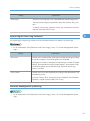
System Log for Device Log Collection.....................................................................................................113
Firmware Management System Log........................................................................................................113
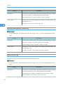
Package Management System Log.........................................................................................................114
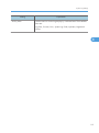
Server Access Log.....................................................................................................................................114
User Account Management..........................................................................................................................116
Accessing the User Account Settings.......................................................................................................116
User Account Settings Screen Overview.................................................................................................117
Managing User Accounts.........................................................................................................................120
Managing Users in Groups......................................................................................................................124
4. Printer Management
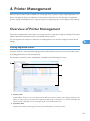
Overview of Printer Management................................................................................................................125
Viewing Registered Printers......................................................................................................................125
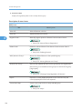
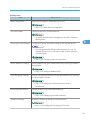
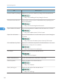
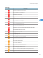
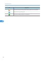
Explanation of status icons........................................................................................................................130
Device Configuration Functions....................................................................................................................133
Configuring Device Log Transfer..............................................................................................................133
Overwriting Access Accounts...................................................................................................................133
Setting an Address Book...........................................................................................................................135
Setting User Information (Access Control Information)..........................................................................135
Deleting Logs Stored on Devices.............................................................................................................135
Enabling the Trap Setting for Devices......................................................................................................136
Disabling the Trap Setting for Devices.....................................................................................................136
Manual Device Registration..........................................................................................................................138
Registering Devices...................................................................................................................................138
Deleting Devices........................................................................................................................................140
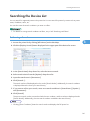
Searching the Device List..............................................................................................................................141
Performing a Search..................................................................................................................................141
Searching with Filters.....................................................................................................................................142
11
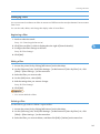
Applying a Filter........................................................................................................................................142
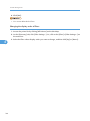
Managing Filters........................................................................................................................................143
Managing Printer Properties.........................................................................................................................145
Displaying Printer Properties.....................................................................................................................145
Configuring Settings for a Device............................................................................................................147
Printer Properties Screen Tabs..................................................................................................................149
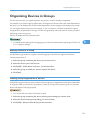
Organizing Devices in Groups.....................................................................................................................153
Moving Devices to a Group.....................................................................................................................153
Clearing Group Registration of Devices..................................................................................................153
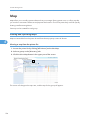
Map................................................................................................................................................................154
Viewing and Operating Maps.................................................................................................................154
Creating and Accessing Maps.................................................................................................................158
Editing a Map............................................................................................................................................160
Deleting Maps...........................................................................................................................................161
Device Error Notification...............................................................................................................................163
Specifying Error E-mail Notification Recipients......................................................................................163
Creating an E-mail Recipient List..............................................................................................................163
Error Report....................................................................................................................................................165
Viewing Error Reports...............................................................................................................................165
Device and User Counters............................................................................................................................166
Device Counters........................................................................................................................................166
Configuring Counter Collection by User.................................................................................................167
Exporting User Counter Information........................................................................................................168
Batch Device Configuration..........................................................................................................................171
Batch Configuration Procedure................................................................................................................171
Configure the Details for Batch Settings..................................................................................................172
Configure a Temporary Access Account.................................................................................................189
Specify Batch Execution Schedule...........................................................................................................190
Configure Notification Settings................................................................................................................191
Displaying the Batch Configuration Results.............................................................................................191
Task List...........................................................................................................................................................193
Displaying the Task List.............................................................................................................................193
Managing Tasks........................................................................................................................................194
12
5. Log Management
Job Log...........................................................................................................................................................197
Overview of Job Log.................................................................................................................................197
Displaying Job Log....................................................................................................................................198
Access Log......................................................................................................................................................206
Overview of Access Log...........................................................................................................................206
Displaying Access Log..............................................................................................................................207
Job and Access Log Searching.....................................................................................................................213
Advanced Search for Logs.......................................................................................................................213
Repeating the Search with Different Conditions.....................................................................................213
Canceling the Search................................................................................................................................213
Details of Log Data: Search logs..............................................................................................................214
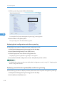
System Log.....................................................................................................................................................217
Overview of System Log...........................................................................................................................217
Displaying System Log..............................................................................................................................217
Exporting Logs................................................................................................................................................220
Log Output Tool.............................................................................................................................................221
Overview of Log Output Tool...................................................................................................................221
Log Manual Output Tool..........................................................................................................................221
Log Periodic Output Tool..........................................................................................................................226
Specifying Log Items to Export.................................................................................................................231
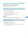
6. Firmware Management
Overview of Firmware Management...........................................................................................................233
Updating Firmware........................................................................................................................................234
Service Settings (Windows Server 2003 or Later).................................................................................234
Configuring Initial Settings........................................................................................................................235
Selecting a Firmware Version...................................................................................................................235
Specifying a Firmware Update Schedule................................................................................................236
Scheduling the Firmware Update............................................................................................................237
Checking Firmware Update Results.........................................................................................................238
Displaying Firmware Management..............................................................................................................240
Displaying All the Firmware......................................................................................................................240
Displaying Firmware Details from the Firmware Menu..........................................................................241
13
Displaying Firmware Details from the Properties Icon............................................................................241
Checking Release Notes...........................................................................................................................242
Deleting Firmware Management..................................................................................................................243
Deleting a Selected Firmware..................................................................................................................243
Deleting Old Firmware Versions..............................................................................................................243
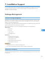
7. Installation Support
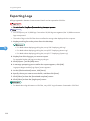
Package Management..................................................................................................................................245
Overview of Package Management.......................................................................................................245
Displaying the Package List......................................................................................................................245
Creating Packages....................................................................................................................................248
Uploading Packages.................................................................................................................................252
Notifying by Email.....................................................................................................................................253
Deleting Packages.....................................................................................................................................253
Allocation Files...............................................................................................................................................254
Overview of Allocation Files....................................................................................................................254
Downloading Allocation Files..................................................................................................................254
Editing Allocation Files..............................................................................................................................254
Uploading Allocation Files.......................................................................................................................258
Scenario Files.................................................................................................................................................259
Overview of Scenario Files.......................................................................................................................259
Downloading and Editing Scenario Files................................................................................................264
Uploading Scenario Files.........................................................................................................................264
Printer Icon and Driver Setting..................................................................................................................265
Port Setting Example.................................................................................................................................272
Other Setting Example..............................................................................................................................279
8. Maintenance of Remote Communication Gate S Server
Overview of Server Maintenance................................................................................................................285
ManagementTool Functions.....................................................................................................................285
Starting ManagementTool........................................................................................................................286
Managing the Server....................................................................................................................................287
Starting and Stopping Service..................................................................................................................287
Backing Up Server Data...........................................................................................................................288
Periodic Backup Tool................................................................................................................................289
14
Restoring Server Data...............................................................................................................................295
Initializing the Server Data to Installation Defaults.................................................................................296
Changing the Server IP Address and Host Name......................................................................................298
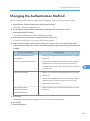
Changing the Authentication Method..........................................................................................................299
Changing the Server......................................................................................................................................300
Before Changing the Server.....................................................................................................................300
Setting Up the New Server.......................................................................................................................300
Acquiring Group Information.......................................................................................................................302
Managing Device Data................................................................................................................................303
Importing Data...........................................................................................................................................303
Exporting Data...........................................................................................................................................304
9. Authentication Management
Overview of Authentication Management..................................................................................................305
Installing Authentication Manager...........................................................................................................305
Starting and Closing Authentication Manager.......................................................................................306
Using Help.................................................................................................................................................307
Settings for Windows Vista.......................................................................................................................308
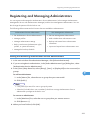
Registering and Managing Administrators..................................................................................................309
Adding and Removing Authentication Service Administrators..............................................................309
Adding and Removing a User Management Administrator (Basic Authentication Only)...................310
Changing the Built-in User's Password....................................................................................................310
Managing Authentication Settings...............................................................................................................312
Specifying the Authentication Method....................................................................................................312
Displaying the Current Authentication Settings.......................................................................................316
Default Setting for Authentication Method..............................................................................................316
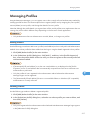
Managing Profiles.........................................................................................................................................317
Adding Profiles..........................................................................................................................................317
Deleting Profiles.........................................................................................................................................317
Changing Profiles......................................................................................................................................318
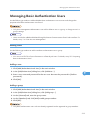
Managing Basic Authentication Users.........................................................................................................319
Adding Users.............................................................................................................................................319
Deleting Users or Groups.........................................................................................................................320
Changing a User's or Group's Settings...................................................................................................320
15
Setting User Preferences...........................................................................................................................320
Exporting Basic Authentication Users......................................................................................................320
Importing Basic Authentication Users......................................................................................................321
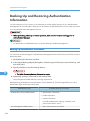
Backing Up and Restoring Authentication Information...............................................................................322
Backing Up Authentication Information...................................................................................................322
Restoring Authentication Information.......................................................................................................323
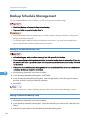
Backup Schedule Management...................................................................................................................324
Adding a Scheduled Backup Task...........................................................................................................324
Editing a Scheduled Backup Task............................................................................................................324
Deleting a Scheduled Backup Task.........................................................................................................325
Suspending and Resuming a Scheduled Task........................................................................................325
10. Other Management
Encrypting Communication Channels..........................................................................................................327
SSL Settings for Servers.............................................................................................................................327
SSL Settings for a Client Computer..........................................................................................................334
SSL Settings between the LDAP (NDS) Server and Remote Communication Gate S..........................335
SSL Settings between a Device and Remote Communication Gate S..................................................336
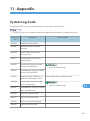
11. Appendix
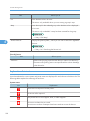
System Log Code...........................................................................................................................................339
Log Information Contained in CSV Files......................................................................................................355
Job Log Information that is Output to CSV Files......................................................................................355
Access Log Information that is Output to CSV Files................................................................................364
Sorting Order of Detailed Log Items............................................................................................................372
Sorting Order of Detailed Job Log Items.................................................................................................372
Sorting Order of Detailed Access Log Items...........................................................................................378
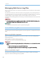
Managing Web Server Log Files.................................................................................................................380
Location of Web Server Log Files............................................................................................................380
About the Batch File for Deleting Logs.....................................................................................................381
Required Settings If the Server Login Account is Changed........................................................................382
CSV Format Reference..................................................................................................................................383
Batch Grouping CSV File Format.............................................................................................................383
Device Registration CSV File Format.......................................................................................................388
ManagementTool CSV File Formats........................................................................................................389
16
Address Book CSV File Format................................................................................................................395
User Information (Access Control) CSV Format......................................................................................399
Counter Notification CSV File and Web Interface Item Names............................................................400
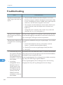
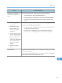
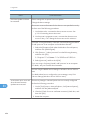
Troubleshooting.............................................................................................................................................402
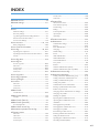
INDEX...........................................................................................................................................................405
17
18
1. What You Can Do with Remote
Communication Gate S
Remote Communication Gate S is a software application for managing your printers. Rather than having
to maintain each printer separately, Remote Communication Gate S shows you information about your
printers' status, logs, and errors in one location. It also eases printer maintenance by automatically
downloading and installing firmware updates, and provides a mechanism for efficiently distributing device
drivers to users in your organization.
1
This chapter explains the major features of Remote Communication Gate S.
Remote Communication Gate S Editions
There are two editions of Remote Communication Gate S, allowing you to implement a device management
solution that fits your organization's system integration and budgetary requirements.
• Remote Communication Gate S Pro for @Remote Enterprise
See p.20 "Overview of Remote Communication Gate S Pro for @Remote Enterprise".
• Remote Communication Gate S Pro with Remote Communication Gate S Pro @Remote Connector
See p.21 "Overview of Remote Communication Gate S Pro with Remote Communication Gate S
Pro @Remote Connector".
Product Edition Naming Conventions
In this manual, the following names are used to describe the different editions of Remote Communication
Gate S:
• “Remote Communication Gate S” is used as a general term for all editions of Remote Communication
Gate S.
• “Remote Communication Gate S Pro” is used when an explanation applies to Remote Communication
Gate S Pro for @Remote Enterprise.
• “Remote Communication Gate S Pro @Remote Connector” is abbreviated as “@Remote
Connector”.
19
1. What You Can Do with Remote Communication Gate S
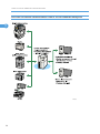
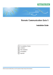
Overview of Remote Communication Gate S Pro for @Remote Enterprise
1
BRW001S
20
Remote Communication Gate S Editions
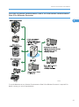
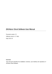
Overview of Remote Communication Gate S Pro with Remote Communication
Gate S Pro @Remote Connector
1
BRW005S
To use the @Remote service, Remote Communication Gate S Pro @Remote Connector is required. For
details, contact your service representative.
21
1. What You Can Do with Remote Communication Gate S
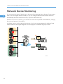
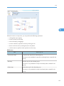
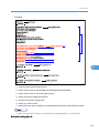
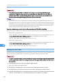
Network Device Monitoring
1
You can monitor the status all the devices on the network by registering them to Remote Communication
Gate S. You can register devices manually, or you can configure Remote Communication Gate S to
automatically search the network for devices, a process called "discovery".
When an error occurs in a device, you can have an e-mail sent to specified e-mail addresses, notifying
the concerned parties of the condition.
In addition, devices can be organized into groups, which can ease management by dividing a large
number of devices into logical categories. You can apply error notification to groups as well.
BRY001S
22
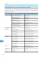
Network Device Monitoring
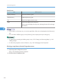
Step-by-Step Summary
Step
Action
Description and Reference
1
Initial Settings
The initial settings wizard guides you through the necessary settings to begin
using Remote Communication Gate S. Settings include:
1
• Proxy and e-mail server settings
• Group creation
• Device polling settings
• Device discovery settings
• See p.51 "Initial Settings Wizard".
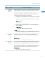
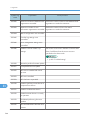
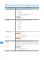
2
Device
Registration
Remote Communication Gate S provides several different methods for
registering devices.
• If you have a large number of devices to register, you can use the
Discovery function to automatically search the network for devices. The
Discovery function can also periodically scan the network for new
devices.
• See p.55 "Initial Discovery Settings".
• If you only need to register a few devices, or you only want to register
certain devices, you can register devices manually.
When registering devices manually, you can specify devices by host
name, in addition to IP address. If you use a DHCP server to assign IP
addresses, registering devices by host name allows you to correctly
manage devices, even if their IP addresses change.
• See p.138 "Manual Device Registration".
• If you are migrating from another application, such as Web
SmartDeviceMonitor, you can import a CSV file of device information
exported from your previous application.
• See p.303 "Importing Data".
23
1. What You Can Do with Remote Communication Gate S
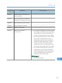
Step
3
1
Action
Group
Creation
Description and Reference
Creating groups for organizing devices can greatly simplify device
management. There are two types of groups in Remote Communication Gate
S:
• Categories
Categories are the top level organizational unit for groups. You can
create up to three categories.
• Groups:
You can create groups within categories. Groups can be nested up to
five levels deep.
There are two ways to create a group hierarchy:
• Use the Remote Communication Gate S Web interface to create
categories and groups one at a time.
• See p.61 "Category Settings".
• Import a CSV file that contains the group information for one category.
• See p.303 "Importing Data".
24
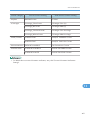
Network Device Monitoring
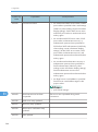
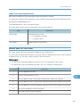
Step
4
Action
Registering
Devices in
Groups
Description and Reference
Registering devices to groups allows you to simplify management by logically
organizing devices by criteria such as department, function, and location.
Devices can be registered to multiple groups in different "categories". For
example, one category can organize devices by physical location, and
another category can organize devices by function. Each device can be
registered to the appropriate group in each category.
1
• By preparing a CSV file specifying group information, you can register
a large number of devices to groups at once. The CSV file can specify
conditions so you can, for instance, register all devices in a certain IP
address range to a group.
• See p.61 "Category Settings".
• For finer control over group registration, you can register devices to
groups individually.
• See p.153 "Organizing Devices in Groups".
• If you import a prepared CSV file using ManagementTool in step 2, this
step is not necessary; the CSV file also contains the group information.
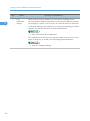
5
Device List
Display
Settings
The device list is where you can view the status and information about
registered devices. You can customize what information is displayed in the
display list.
• See p.87 "Printer Management List Display Settings".
6
Personal
Address Book
Settings
You can create a personalized address book from Remote Communication
Gate S users. When assigning recipients for notifications such as error
notifications, you can assign recipients from your personal address book.
If your organization has many users, creating a personal address book can
help you access more quickly the e-mail addresses that you use most.
• See p.67 "Personal Address Book Settings".
25
1. What You Can Do with Remote Communication Gate S
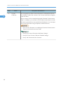
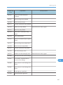
Step
7
1
Action
Error
Notification
Settings
Description and Reference
When an error occurs in a device, you can have a notification sent to
concerned parties. Different types of errors can be sent to different recipients.
For example, if a printer is low on toner, an e-mail can be sent to personnel
in charge of ordering printer supplies; if a printer stops responding to network
requests, an e-mail can be sent to a network administrator.
• See p.163 "Device Error Notification".
Error notifications can be set for entire groups. When an error occurs in any
printer in the group, an e-mail is sent to the appropriate destination.
• See p.61 "Category Settings".
26
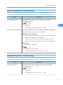
Device Counter Management
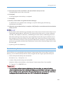
Device Counter Management
Remote Communication Gate S collects counter information from all registered devices. Counters include
information such as the number of color pages printed and the number of sent faxes.
You can view counter information in the Remote Communication Gate S web interface, and you can have
counter data e-mail to you. For example, you can be informed every month via e-mail of how many copies
have been printed.
1
BRY002S
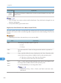
Step-by-Step Summary
Step
1
Action
Device
Registration
Description and Reference
Before you can collect counter information, you need to register devices.
• See p.22 "Network Device Monitoring".
2
Display Settings
By customizing the device list display, you can view device counter
information from Remote Communication Gate S.
After configuring the device list to display counter information, when you
export the device list, counter information is included in the exported file.
• See p.87 "Printer Management List Display Settings".
• See p.125 "Viewing Registered Printers".
27
1. What You Can Do with Remote Communication Gate S
Step
3
1
Action
Counter
Collection
Description and Reference
You can specify how often counter information is collected from devices
and whether to collect user counters. User counters track device usage on
a per-user basis.
Device counters can be viewed and exported in Remote Communication
Gate S. In addition, you can have a CSV file that contains device counter
information periodically sent to specified e-mail addresses. You can export
user counter information using a separate command line tool.
• User counter information is not displayed in Remote Communication
Gate S, and cannot be sent via e-mail.
• See p.84 "Counter Information Notification Settings".
• See p.82 "User Counter Collection Schedule Settings".
• See p.166 "Device and User Counters".
28
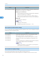
Device Address Book Management
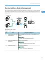
Device Address Book Management
You can import and export address book data (e-mail addresses, fax numbers, etc.) on devices registered
with Remote Communication Gate S. The function allows you to quickly share the address data from one
device with other devices. You can also edit an exported file, then import it to quickly make changes to the
address book.
1
BRY003S
The following is a step summary:
Step-by-Step Summary
Step
1
Action
Description and Reference
Address Book Export from a Export the address book information of a selected device to a
Selected Device
CSV file.
• See p.125 "Viewing Registered Printers".
2
Edit CSV file (Address Book
Information)
Edit the CSV file as desired.
• See p.395 "Address Book CSV File Format".
3
Address Book Import
Import the CSV file devices.
• See p.135 "Setting an Address Book".
29
1. What You Can Do with Remote Communication Gate S
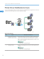
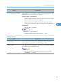
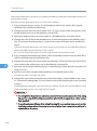
Printer Driver Distribution to Users
1
You can create packages of drivers and other applications and distribute them to general users. Users can
install drivers and other applications easily using these packages.
BRY004S
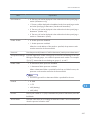
Step-by-Step Summary
Step
Action
1
Packager download and
installation from the Server
Description and Reference
Download the Packager application installer from the Remote
Communication Gate S server to the administrator's computer.
Then, run the downloaded Packager application installer on the
administrator's computer.
• See p.248 "Creating Packages".
2
Package Creation
Create a new package that you want to install on general users'
computer.
• See p.248 "Creating Packages".
30
Printer Driver Distribution to Users
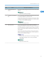
Step
3
Action
Package Upload to the
Server
Description and Reference
Upload the created package to the Remote Communication Gate
S server.
1
• See p.252 "Uploading Packages".
4
Customize user allocation
files
You can optionally create individual setting files that can be used
to customize installation for individual users.
Download the allocation file from Remote Communication Gate
S, edit it to customize settings for individual users, and then upload
it to include it in the installation package.
• See p.254 "Allocation Files".
5
Edit scenario files
You can optionally edit the scenario file for an installation
package to extend the functionality of the installer. A scenario file
is an INI file that defines installation settings. Editing scenario files
lets you customize the installation beyond what is possible using
only Packager.
Download a scenario file from Remote Communication Gate S,
edit it to customize the installation settings, and then upload it to
include it in the installation package.
• Once you edit a scenario file, do not use Packager to modify
the package; Packager cannot correctly read edited
scenario files.
• See p.259 "Scenario Files".
31
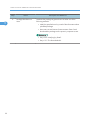
1. What You Can Do with Remote Communication Gate S
Step
6
1
Action
Package Distribution to
Users
Description and Reference
Distribute the package to general users in either one of the
following methods:
• Notify the specified users by e-mail of the information about
uploaded package.
• Have users access Remote Communication Gate S and
download the package via the printer's properties screen.
• See p.253 "Notifying by Email".
• See p.151 "The Download tab".
32
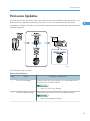
Firmware Updates
Firmware Updates
The most recent version firmware or other version of firmware is downloaded from the global server. The
device firmware is updated automatically and remote. You can also perform the firmware update
immediately. In addition, notification can be sent to the administrator via e-mail message when the firmware
update is completed.
1
BRY005S
The following is a step summary:
Step-by-Step Summary
Step
1
Action
Proxy Server Settings
Description and Reference
Configure the proxy server settings if your organization uses a
proxy server to access the Internet.
• See p.59 "HTTP Proxy Settings".
2
Firmware Update Settings
Select the firmware version and set the update schedule.
• See p.234 "Updating Firmware".
33
1. What You Can Do with Remote Communication Gate S
Step
3
1
Action
Notification of Firmware
Update Completion
Description and Reference
Select whether or not to receive e-mail notification when the
firmware update is completed so that you can check the result.
• See p.236 "Specifying a Firmware Update Schedule".
34
Batch Configuration of Device Settings
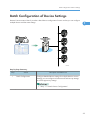
Batch Configuration of Device Settings
Remote Communication Gate S provides a batch device configuration function so that you can configure
multiple devices with the same settings.
1
BRY006S
Step-by-Step Summary
Step
1
Action
Batch Configuration
Description and Reference
Configure detailed device settings for multiple devices at once.
Settings you can configure include network and security settings,
as well as paper tray settings.
• See p.171 "Batch Device Configuration".
35
1. What You Can Do with Remote Communication Gate S
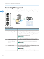
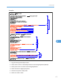
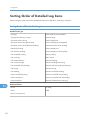
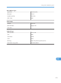
Device Log Management
1
Remote Communication Gate S can collect and display the job and access logs of registered devices. You
can configure which devices to collect logs from, how often to collect logs, and how long to store logs.
BRY007S
Step-by-Step Summary
Step
1
Action
Run the Log Management
Service Settings Wizard
Description and Reference
When you first begin using Remote Communication Gate S, after
registering devices, execute the Log Management Service
Settings Wizard. This wizard guides you through the process of
enabling log transfers for printers, specifying the log collection
interval, and the log storage period.
• See p.57 "Log Management Service Settings Wizard".
2
Configure log collection
settings for individual
devices
If you want to change log transfer settings, or configure the
settings for new devices, you can do so from the device list.
• See p.133 "Configuring Device Log Transfer".
3
View device logs
You can view a list of the collected job and access logs, as well
as view the details of collected logs.
• See p.197 "Job Log" and p.206 "Access Log".
36
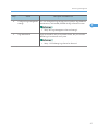
Device Log Management
Step
Action
Description and Reference
4
Configure log management
settings
You can change the log storage period, perform log database
maintenance, and enable/disable the log collection function.
1
• See p.80 "Log Management Service Settings".
5
Log maintenance
Logs are stored for only a set period of time, but you can also
delete logs from devices at any time.
• See p.135 "Deleting Logs Stored on Devices".
37
1. What You Can Do with Remote Communication Gate S
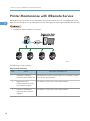
Printer Maintenance with @Remote Service
1
@Remote service is an online service designed to ease printer maintenance. By using @Remote service,
tasks such as ordering new toner, making service calls, and supply use reporting are handled automatically.
• This feature requires @Remote Connector.
BRY008S
The following is a step summary:
Step-by-Step Summary
38
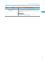
Step
Action
Description and Reference
1
Installation of Remote
Communication Gate S Pro
Install Remote Communication Gate S Pro. For details, contact
your service representative.
2
Registration to the
Communication Server by
the Customer Engineer
For details, contact your service representative.
3
Activation of @Remote
Service by the Customer
Engineer
For details, contact your service representative.
Printer Maintenance with @Remote Service
Step
4
Action
@Remote Settings by the
Administrator
Description and Reference
Access the separate web interface for @Remote service, and
configure the various settings. For details, contact your service
representative.
1
• See p.101 "@Remote Settings".
39
1. What You Can Do with Remote Communication Gate S
1
40
2. Login and Logout
This chapter explains how to access/login to/logout from Remote Communication Gate S.
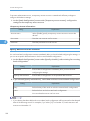
Access
To access Remote Communication Gate S, use one of the following procedures.
2
Access from Server Computer's Start Menu
On the computer where you installed Remote Communication Gate S, you can access the Remote
Communication Gate S web interface from the [Start] menu.
On the [Start] menu, point to [All Programs] > [Remote Communication Gate S], and then select
[StartBrowser].
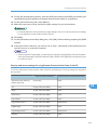
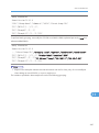
Access from Web Browser
You can access the Remote Communication Gate S Web interface from any computer on the local network.
Condition
URL
http://{host name}:{port number}/mgmt
Without SSL encryption
or
http://{IP address}:{port number}/mgmt
https://{host name}:{port number}/mgmt
With SSL encryption
or
https://{IP address}:{port number}/mgmt
• {host name}: name of the Remote Communication Gate S server
• {IP address}: IP address of the Remote Communication Gate S server
• {port number}: port number specified when Remote Communication Gate S was installed
For example:
• http://192.168.17.21:8080/mgmt
• https://intra.example.org:8443/mgmt
• If 80 is used as the port number, you can omit it from the URL.
41
2. Login and Logout
For example: http://intra.example.org/mgmt
• The page located at "/mgmt" is for redirection purposes only. When you access Remote
Communication Gate S at "http://xxxx:xx/mgmt", you are redirected to the actual login page.
• The default port numbers differ depending on the type of Web server you are using:
• Apache: 8080 (non-secure), 8443 (secure)
2
• IIS: 80 (non-secure), 443 (secure)
• For details about secure connections, see p.327 "Encrypting Communication Channels".
42
Login
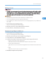
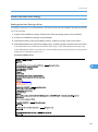
Login
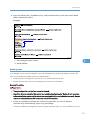
The login screen is displayed when you access Remote Communication Gate S via its URL.
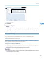
1. Enter a user name and password. If necessary, enter a domain name also.
2. Click [Login].
The Top Page of Remote Communication Gate S appears.
2
• When using Remote Communication Gate S, do not use your browser's [Back] button or other browser
functions. Use only the navigation controls on the content pages.
• If you want to switch users, click the [Logout] button, and then log in again as a different user. Do not
use your browser's [Back] button to redisplay the login screen.
• If you are using Remote Communication Gate S for the first time, take a moment to read the information
that appears when you click the [Readme] icon. This information explains the limitations of Remote
Communication Gate S and provides instructions for its use. To close this screen, click [Close].
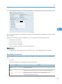
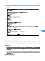
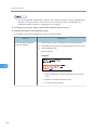
Top Page
After you have successfully logged in, the Top Page for Remote Communication Gate appears. The content
of the Top Page differs depending on whether devices have been registered.
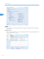
Settings screen
If no devices are registered, the [Settings] screen appears when you log in.
43
2. Login and Logout
2
• If you log in to an account without administrator privileges, the Site Map will appear instead of the
[Settings] screen.
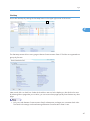
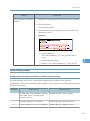
Device list screen
After you have registered devices, or if you imported device information using ManagementTool, the
device list appears when you log in.
44
Login
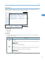
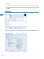
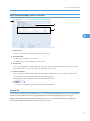
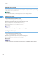
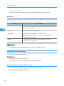
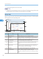
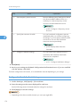
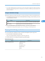
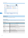
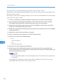
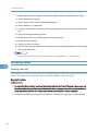
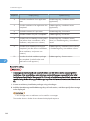
Screen layout
All screens in Remote Communication Gate S have a common layout. This section explains the basic
elements of all screens. The device list screen is used as an example.
1
2
2
3
BXN001S
1. Page header
2. Page content
3. Quick Links
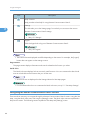
Page header
The page header contains buttons that allow you to access useful functions. The following table
explains the different buttons.
Item
Description
Site Map
The site map contains links to all of the pages in Remote Communication Gate S.
• See p.111 "Site Map Settings".
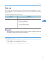
Task
The Task screen shows tasks scheduled and pending tasks for device discovery
and firmware updates, batch settings, and other tasks.
• See p.193 "Task List".
45
2. Login and Logout
Item
Description
Help Contents
Help provides online help for using Remote Communication Gate S.
Settings
2
This link takes you to the Settings page, from which you can access the various
Remote Communication Gate S settings.
• See p.51 "Settings".
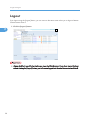
Logout
Click the logout link to log out of Remote Communication Gate S.
• See p.50 "Logout".
• The buttons that are displayed can differ depending on the screen. For example, the [Logout]
button does not appear on the settings screens.
Page content
The page content displays information and controls related to the function you select.
Quick Links
The Quick Links area displays links to commonly used functions. You can customize the Quick Links
area to include links to the functions that you use the most.
• Quick Links are not displayed on the Settings Wizard or Site Map pages.
• For information about how to customize the Quick Links area, see p.111 "Site Map Settings".
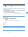
Navigating the Remote Communication Gate S Screens
There are three main ways to navigate through the Remote Communication Gate S screens: using the Site
Map, using the Quick Links area, and using the [Settings] screen. The Quick Links area was explained in
the previous section. The following sections explain the Site Map and [Settings] screen.
46
Login
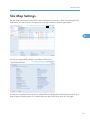
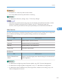
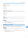
Site Map
Access the Site Map by clicking the Site Map button in the upper right corner of the screen:
2
BXN002S
The Site Map contains links to every page in Remote Communication Gate S. The links are organized into
groups by function.
Next to each link is a check box. Select the check box next to a link to display it in the Quick Links area.
By selecting links to pages that you use often, you can access those pages quickly from almost every other
page.
• Only users with Remote Communication Gate S administrator privileges can customize Quick Links.
The Quick Links settings are shared among all Remote Communication Gate S users.
47
2. Login and Logout
• Only pages that you have sufficient access privileges to view are displayed in the Site Map and Quick
Links areas.
Settings screen
2
Access the [Settings] screen by clicking the [Settings] button in the upper right corner of the screen.
BXN003S
The Settings screen contains links to all of the settings pages in Remote Communication Gate S. The links
are organized into groups by function.
48
Login
• For details about settings, see p.51 "Settings".
2
49
2. Login and Logout
Logout
If you logout using the [Logout] button, you can return to the same screen when you re-login to Remote
Communication Gate S.
2
1. Click the [Logout] button.
BXN004S
• Always click the [Logout] button before you close the Web browser. If you close Internet Explorer
without clicking the [Logout] button, you will remain logged in to Remote Communication Gate S.
50
3. Settings
This chapter describes the various settings that are available in Remote Communication Gate S.
Initial Settings Wizard
When you log in to Remote Communication Gate S for the first time, you need to configure the initial settings
before you begin using the application to manage your devices. The Initial Settings Wizard guides you
through the settings you must configure to begin using Remote Communication Gate S.
The following settings must be configured:
3
• Group Settings
Create new categories and groups for the management of printers.
See p.52 "Group Initial Settings".
• HTTP Proxy Settings
Select whether to use a proxy server when connecting to the global server, and then configure the
proxy server settings if necessary.
See p.53 "HTTP Proxy Initial Settings".
• E-mail Settings
Configure the SMTP server settings so that Remote Communication Gate S can send notification emails.
See p.54 "Email Initial Settings".
• Device Polling Settings
Set the polling time and timeout to collect the device status.
See p.54 "Device Polling Initial Settings".
• Discovery Settings
Configure the settings for automatic printer discovery.
See p.55 "Initial Discovery Settings".
Accessing the Initial Settings Wizard
1. Click the [Settings] button to display the [Settings] screen.
If no devices are registered, the [Settings] screen appears when you log in.
2. Under [Setup Wizard], click [Initial Settings Wizard] to start the wizard.
51
3. Settings
• Even after you complete the Initial Settings Wizard, you can still access the wizard from the [Settings]
screen.
Group Initial Settings
3
The first screen in the wizard is the Group screen. Use this screen to create new categories and groups for
managing printers.
Categories and groups
Categories and groups allow you to organize printers for better management. You can view device details
and perform printer operations for all the printers in a group. The following explains the difference between
a category and a group.
Categories
Categories are the top-level organizational unit and contain groups. You can create a maximum of
three categories. Categories can be used to broadly classify groups by criteria such as department,
floor, etc.
Group
Groups are contained within categories. You can also nest groups within groups to create a more
detailed hierarchy of devices. You can nest groups up to five levels, not including the top-level
category.
By registering printers in groups, you can manage all the printers in a group at once. For example,
you can have a notification sent to the network administrator if a printer in a specified group falters
due to error.
• You cannot register printers directly in categories.
• A printer cannot be registered to multiple groups within the same category, but it can be registered
to a group in another categories.
• You can create a maximum of three categories.
• You can nest groups up to five levels within categories.
Create a category
When you first start Remote Communication Gate S, a category named "Main Group" already exists. Use
the following procedure to add additional categories as necessary.
1. On the menu bar, click [Create] > [New Category].
52
Initial Settings Wizard
2. On the [Category Settings: Create New Category] screen, enter a name for the category
you are creating.
3. Select a color for the category, and add comments if necessary.
4. Click [OK].
Create a new group
Use the following procedure to create a group.
1. Select the category or group in which you want to create a new group, and then, on the
menu bar, click [Create] > [New Group].
3
2. On the [Group Settings: Create New Group] screen, enter a name for the new group you
are creating.
3. Enter comments if necessary.
4. If necessary, specify the e-mail addresses to which error notifications will be sent.
For details about specifying e-mail addresses as destinations for error notifications, see p.163
"Creating an E-mail Recipient List".
5. Click [OK].
6. Repeat this procedure to create more groups as necessary. When you are finished, click
[Next].
• For details about group settings and managing groups, see p.61 "Category Settings".
HTTP Proxy Initial Settings
Remote Communication Gate S accesses the Internet in order to perform function such as remote firmware
updates. If your organization uses a proxy server to access the Internet, you will need to configure the
proxy server settings.
1. On the [HTTP Proxy Settings] screen under <Proxy server>, select whether your network
uses a proxy server to access the Internet.
If you select [Enable], proceed to step 2. If you select [Disable], proceed to step 6.
2. Enter the proxy server's address and port number.
3. Under <User authentication>, select whether to use authentication when connecting to the
proxy server.
If you select [On], proceed to step 4. If you select [Off], proceed to step 5.
4. Enter the user name and password that are used to access the proxy server.
5. Under [Connection test:], click [Perform] to test the connection to the proxy server.
53
3. Settings
6. Click [Next].
• For details about proxy server settings, see p.59 "HTTP Proxy Settings".
Email Initial Settings
3
Remote Communication Gate S can send notifications by e-mail of events such as printer errors and
discovery of new printers. Configure the SMTP server settings in order to enable Remote Communication
Gate S to send e-mail.
1. Under <SMTP>, enter the SMTP server address, port number, and an e-mail address.
The e-mail address will be used as the sender for e-mails sent from Remote Communication Gate S.
2. Under <Authentication>, configure the authentication settings for accessing the SMTP server.
3. Enter an e-mail address in [Email address for SMTP server connection test:], and then click
[Perform].
A confirmation e-mail will be sent to the address you entered. Check that the sent e-mail arrives. If it
does, the server settings are correct.
4. Click [Next].
• For details about e-mail server settings, see p.60 "Email Settings".
Device Polling Initial Settings
Remote Communication Gate S periodically polls registered printers in order to obtain their status. You can
configure how frequently Remote Communication Gate S polls printers, and the length of time it waits for
a response.
1. On the [Device Polling Settings] screen, enter the polling interval and polling timeout
settings.
2. Under <Excluded IP Address>, specify any IP address ranges you want to exclude from
polling.
3. Click [Next].
• The "polling interval" is the time between the conclusion of the previous status polling and the start of
the next.
• For details about status polling settings, see p.69 "Status Polling".
54
Initial Settings Wizard
Initial Discovery Settings
Remote Communication Gate S can scan the network for printers, and it can also scan computers for devices
connected via USB. This process is called "discovery". Discovered devices are automatically registered in
Remote Communication Gate S. In order to discover printers, you must configure the discovery settings.
Select search target device
1. On the [Discovery Settings] screen under [Select search target device], select whether to
search for network or local (USB) printers.
3
2. Enter the authentication information based on your selection for [Select search target
device].
• If you selected [Network device], enter the user name and password used to connect to network
printers.
• If you selected [Local device], enter the user name and password of the Windows domain
administrator.
Protocol
1. Select the protocol to use when connecting to and gathering information from printers.
2. Configure the settings based on the protocol you selected:
• <SNMPv1,v2>
If you have selected [SNMPv1,v2] or [SNMPv3 priority], enter the read and write community
names, which are used to read and write information when using the SNMPv1 or SNMPv2
protocols.
• <SNMPv3>
If you have selected [SNMPv3] or [SNMPv3 priority], enter the user name and password for
accessing printers using the SNMPv3 protocol. Then, select whether to use the MD5 or SHA1
algorithm for authentication. Enter the encryption password and MIB context.
3. Select whether to automatically set the trap function for printers.
Search range
1. Select the search method to use for printer discovery.
2. Specify the IP address range or subnet to search within for new printers.
• [Manual entry]
Manually input the IP address ranges or subnets to search within.
55
3. Settings
• [Import CSV file]
Specify a CSV file that contains the IP address ranges or subnets to search within.
• [Retrieve network information from router]
Specify a subnet, and obtain the subnet information from routers on the subnet.
3. If you selected [Network Search], specify the IP addresses to exclude from the search.
Specify schedule
3
1. Specify when to perform the discovery search.
2. If you selected [Set schedule], specify the schedule for performing discovery search.
3. Enter the number of seconds to wait for a response from printers.
Notification settings
1. Select whether to send a notification when discovery is complete.
2. If you select [Notify], click [Notification Settings...] to configure the notification settings.
3. Click [Next].
Task List
1. On the [Discovery Task List] screen, review the summary of the discovery settings. Use the
[Edit] menu to modify your settings.
2. Click [Next].
This completes the Initial Settings Wizard.
• For details about discovery settings, see p.71 "Discovery Settings".
• For information about the task list, see p.193 "Task List".
56
Log Management Service Settings Wizard
Log Management Service Settings Wizard
In order to collect log data, you must specify the printers whose logs you want to collect and the types of
logs you require. The [Log Management Service Settings Wizard] guides you through the settings for
configuring log collection.
• Printer Select
Select the printers whose logs you want to collect.
See p.57 "Select device".
3
• Device Log Transfer Settings
Specify whether to collect device logs and whether or not to encrypt them during transfer.
See p.57 "Device Log Transfer Settings".
• Specify Log Storage Period
See p.58 "Specify Log Storage Period".
Accessing the Log Management Service Settings Wizard
1. Click the [Settings] button
in the upper-right corner of the screen.
2. Under [Setup Wizard], click [Log Management Service Settings Wizard] to start the wizard.
Select device
1. On the [Select device] screen, select the printers whose logs you want to collect.
2. Click [Next].
Device Log Transfer Settings
1. On the [Device Log Transfer Settings] screen, select the settings you want to apply to the
printers.
2. Click [Next].
• For details about the log management settings, see p.80 "Log Management Service Settings".
57
3. Settings
Specify Log Storage Period
1. On the [Specify Log Storage Period] screen, select the length of time you want logs to be
stored for.
2. Click [Next].
This completes the Log Management Service Settings Wizard.
3
58
System Settings
System Settings
This section explains the Remote Communication Gate S system settings. System settings include proxy
settings, e-mail server settings, group settings, address book settings, and date display settings.
You can access any of the various systems settings screens from the [Settings] screen:
HTTP Proxy Settings
Remote Communication Gate S accesses the global server in order to perform functions such as remote
firmware updates. If your organization uses a proxy server to access the Internet, you will need to configure
the proxy server settings.
3
<Proxy server>
Setting
Proxy server:
Explanation
Select whether your network uses a proxy server to connect to the
Internet.
[Enable]
Connection is through a proxy server.
[Disable]
Connection is direct (not through a proxy server).
• Default: [Disable]
• Remote Communication Gate S connects to the Internet to access
the global server for tasks such as remote firmware updates.
Proxy server name ( or
address):
Enter the IP address or host name of the proxy server.
Port No.:
Enter the port number to use for communicating with the proxy server.
59
3. Settings
<User authentication>
Setting
User authentication:
Explanation
Specify whether to perform authentication when connecting to the
proxy server.
[On]
Perform authentication.
[Off]
3
Do not perform authentication.
• Default: [Off]
User name:
Enter the user name for authentication.
Password:
Enter the password for authentication.
Domain name:
Enter the domain name for authentication.
Connection test:
Click [Perform] to test the connection to the proxy server.
Email Settings
Remote Communication Gate S can send notifications by e-mail of events such as printer errors and
discovery of new printers. This section explains the SMTP server settings.
<SMTP>
Setting
Explanation
SMTP server:
Enter the IP address or host name of the SMTP server to use for sending
event notification e-mail.
SMTP port No.:
Enter the port number to use for communicating with the SMTP server.
• Default: 25
Server mail address:
60
Enter the e-mail address for the server. This e-mail address is used as
the sender address when Remote Communication Gate S sends e-mails.
System Settings
<Authentication>
Setting
Authentication type:
Explanation
Select an authentication method.
[None]
Authentication is not applied.
[POP3]
Authentication is through the POP3 server.
[SMTP]
3
Authentication is through the SMTP server specified in [SMTP
server:].
• Default: [None]
POP3 server:
Enter the IP address or host name of the POP3 server that will provide
authentication.
POP3 port No.:
Enter the port number to use when communicating with the POP3 server.
Authentication account:
Enter the user name for authentication with the POP3 server.
Authentication password:
Enter the password for authentication with the POP3 server.
Email address for SMTP server Enter an e-mail address. A test e-mail will be sent to the address to
connection test:
confirm that the SMTP server settings are correct.
SMTP server connection test:
Click [Perform]. A test e-mail will be sent to the e-mail address specified
in [Email address for SMTP server connection test:].
• The [POP3 server:] and [POP3 port No.:] settings can be specified/changed only if [POP3] is selected
in [Authentication type:].
• The [Authentication account:] and [Authentication password:] settings can be specified/changed only
if [POP3] or [SMTP] is selected in [Authentication type:].
Category Settings
You can configure the group categories and groups that are displayed on the [Directory] tab. After you
create groups, you can register devices to them in order to simplify device management. You can also
create a floor map for each group, from which you can visually confirm the status and location of printers
in a group.
61
3. Settings
ManagementTool also provides the following group management functions:
• Creating a category (when using an authentication method other than Basic Authentication)
• Creating groups by importing a CSV file
• For details about registering printers to groups, see p.153 "Organizing Devices in Groups".
• For details about creating floor maps, see p.154 "Map".
• For details about ManagementTool group functions, see p.303 "Managing Device Data" and
p.302 "Acquiring Group Information".
3
Group Settings screen
The [Group Settings] screen allows you to view and manage groups.
1
2
3
4
BRY010S
1. [Create], [Edit], and [Map] menus
See the "Group settings screen menus" below for a description of the items in these menus.
2. Group view
You can view the group tree structure, and select which groups to apply procedures to. You can also change
the order of the categories.
3. Group information export
You can export group information as a CSV file.
4. CSV file import
You can import a CSV file to register several printers to groups at one time.
• If this section of the screen is not be visible because the group view area is too large, clicking "Go to batch
grouping with CSV file" on the upper part of the screen will jump you to this section.
62
System Settings
Group settings screen menus
[Create] menu
Item
Allows you to
New Group
Create a new group within the currently selected category or group.
New Category
Create a new category.
• You can create a maximum of three categories.
3
[Edit] menu
Item
Edit
Allows you to
Edit the details of the selected category or group.
• For details about editing groups, see p.61 "Category Settings".
Move
Move the selected group within the category.
• For details about moving groups, see p.61 "Category Settings".
Delete
Delete the selected category or group.
• If the group you are deleting has subgroups, the subgroups will be
deleted, too.
• You cannot delete a category if it is the only one in the [Group list:].
[Map] menu
Item
Create New Map...
Allows you to
Create a floor map for the selected group.
• You cannot create a floor map for a category.
Edit Map
Edit the floor map for the currently selected group.
Delete Map
Delete the floor map for the currently selected group.
63
3. Settings
• For details about maps, see p.154 "Map".
Creating a new category
1. Access the [Group Settings] screen.
2. On the [Create] menu, select [New Category].
3
3. Configure the following settings for the new category:
Setting
Explanation
Category name:
Enter the name of the newly created category.
Icon color:
Select the color of the newly created group's icon.
• [Blue]
• [Green]
• [Yellow]
• Default: [Blue]
Comment:
In the text box, enter any necessary comments.
• You can create a maximum of three categories.
Changing the order of categories
1. In the group tree view, select a category.
2. Click [Up] or [Down] to move the category.
Creating a new group
1. Access the [Group Settings] screen.
2. Select the category or group in which you want to create the new group.
3. On the [Create] menu, select [New Group].
4. Configure the following settings for the new group:
64
System Settings
Setting
Explanation
Group name:
Enter the name of the group you want to create.
Comment:
In the text box, enter any necessary comments.
Email address list for error
notification:
You can have Remote Communication Gate S send an e-mail to
specified recipients when an error occurs in any printer registered in the
group.
• For details on managing the error notification list, see p.163
"Device Error Notification".
3
[Edit] menu
Item
Allows you to
Select All
Select all error conditions displayed in [Email address list for error
notification:].
Clear All
Clear all error conditions selected in [Email address list for error
notification:].
Edit Email Address List
Edit e-mail addresses receiving notification of error conditions.
• See p.163 "Creating an E-mail Recipient List".
Add Email Addresses
Add e-mail addresses for notification of error conditions.
• See p.163 "Creating an E-mail Recipient List".
Export...
Export the list of errors set to send e-mail notifications and the recipient
e-mail addresses to a CSV file.
• You can nest up to five levels of group.
Moving a group
1. Access the [Group Settings] screen.
2. Select the group that you want to move.
3. On the [Edit] menu, select [Move].
65
3. Settings
4. On the screen that appears, select the group that you want to move the group into.
5. Click [OK].
The group is moved into the specified group.
• You can only move a group within its own category; you cannot move a group into a different
category.
3
Editing a category or group
1. Access the [Group Settings] screen.
2. Select the category or group that you want to edit.
3. On the [Edit] menu, select [Edit].
4. Edit the settings for the category or group.
The settings that you can edit for both categories and groups are the same as those you specified when
creating those categories and groups.
• For details about categories settings, see p.64 "Creating a new category".
• For details about group settings, see p.64 "Creating a new group".
Deleting a category or group
1. Access the [Group Settings] screen.
2. Select the group that you want to delete.
3. On the [Edit] menu, select [Delete].
Exporting group information
1. Access the [Group Settings] screen.
2. In [Export CSV], select the category that contains information you want to export, and then
click [Export].
3. In the dialog box that appears, click [Save].
4. Specify a path and file name for the CSV file, and then click [Save].
66
System Settings
Batch group registration
If you have a large number of printers to register to groups, you can create and import a CSV file that
specifies the group assignments. To do this, use either the [Group Settings] screen or ManagementTool to
export the group information as a CSV file. Then edit the exported CSV file to specify the groups to which
the printers are assigned.
• Create the desired group hierarchy in Remote Communication Gate S.
1. Export a CSV file that contains the group information for the category you want to populate.
See p.66 "Exporting group information".
3
2. Edit the CSV file to specify the group assignment information.
See p.383 "CSV Format Reference".
3. Click [Category Settings] on the Site Map.
4. In [Import CSV], click [Browse...] and select the CSV file you want to import. Or, enter the
path to the CSV file you want to import.
5. Select the category you want to import the group information into from the drop-down list.
6. Click [Processed].
Remote Communication Gate S will import the specified file. If any errors occur, they will be displayed
beneath the drop-down list.
• You can also export group information using ManagementTool. For details, see p.304 "Exporting
Data".
Personal Address Book Settings
You can create a personal list of e-mail addresses. You can refer to this list when assigning e-mail addresses
for error notification, discovery notification, etc. You create your personal address book from the e-mail
addresses in the Remote Communication Gate S user list.
The personal address book is unique to every Remote Communication Gate S user with administrator
privileges.
67
3. Settings
Setting
Search user:
Explanation
If you enter part of an account name, and then click [Search], the relevant
account appears.
To clear the text box, click [Clear Search].
• Only complete match searching is possible in a Windows
authentication (NT compatible or native) domain. For this reason,
you must enter the entire account name when searching in a
Windows authentication domain.
3
Server Email Address
This is a list of e-mail addresses registered in the address book of the
server. Select an e-mail address from the list, and then click [Add]. The email address is added to [Email address list for notification:].
Email address list for
notification:
This is a list of e-mail addresses registered in a personal address book.
Click [Remove] to delete an address registered in [Email address list for
notification:].
Select the e-mail address you want to delete, and then click [Remove].
Multiple addresses can be selected.
Select Date Display Format
You can select the display format for the dates that are displayed in lists, such as the device list and log
lists.
Setting
Display format:
Explanation
Select the display format of dates for lists.
• Displayed in the order of year, month, and day. (YYYY/MM/DD).
• Displayed in the order of month, day, and year. (MM/DD/YYYY).
• Displayed in the order of day, month, and year. (DD/MM/YYYY).
• The default format is month, day, and year. (MM/DD/YYYY).
68
Device Management Settings
Device Management Settings
This section explains the settings that determine how Remote Communication Gate S manages the devices
connected to it.
Status Polling
Status Polling determines the frequency at which Remote Communication Gate S obtains the status of
devices and the time it waits for a response before cancelling the status poll.
You can exclude certain IP addresses from being polled.
3
• The "polling interval" is the time between the conclusion of the previous status polling and the start of
the next status polling.
Setting
Interval between polling for
status information
Explanation
Specify the frequency at which Remote Communication Gate S polls
devices for their status. Enter a number and select [min.], [hour(s)], or
[day(s)] from the menu.
The time you specify here is the time that will elapse between polling.
• Default: 1 hour
• Valid values: 1 min. - 7 days
Polling interval time for tray,
toner/ink information
Specify the frequency at which Remote Communication Gate S polls
devices for their paper tray levels, and toner/ink status. Enter a number
and select [min.], [hour(s)], or [day(s)] from the menu.
The time you specify here is the time that will elapse between polling.
• Default: 3 hours
• Valid values: 1 min. - 7 days
69
3. Settings
Setting
Polling interval time for other
information
Explanation
Specify the frequency at which Remote Communication Gate S polls
devices for other status information. Enter a number and select [min.],
[hour(s)], or [day(s)] from the menu.
The time you specify here is the time that will elapse between polling.
• Default: 6 hours
3
• Valid values: 1 min. - 7 days
Interval between collection of Specify the frequency at which Remote Communication Gate S polls
internal and administrator
devices for the collection of internal and administrator counters. Enter a
number and select [min.], [hour(s)], or [day(s)] from the menu.
counters
The time you specify here is the time that will elapse between polling.
• Default: 1 day
• Valid values: 1 min: - 7 days
Polling timeout:
Enter the number of seconds to wait for a response from a device.
If the machine receives no response when polling a device, it continues
attempting polling for a specified period. Polling is cancelled after this
period.
• Default: 3 sec.
• Valid values: 0.5 - 60 sec.
• Periodic polling cannot retrieve the following information from devices that are in energy saving mode:
• Log transfer settings
• SSL settings
• Transmission counter figures (Send/TX Total B&W Counter, Send/TX Total Color Counter, Fax
Transmission Counter, Scanner Send B&W Counter, and Scanner Send Color Counter)
• To retrieve the latest information from a device, first select the device on the Printer Management
screen. Then, on the [Printer] menu, select [Refresh Selected Device]; or, on the [Printer] menu on the
Printer Properties screen, select [Refresh Device].
70
Device Management Settings
<Excluded IP Address>
Setting
Explanation
Starting address:
Enter the starting IP address of the IP address range that you want to
exclude.
Ending address:
Enter the ending IP address of the IP address range that you want to
exclude.
Subnet mask:
Enter the subnet mask of the IP address range that you want to exclude.
Add
Adds an IP address range to the list of IP address ranges that you want to
exclude.
3
Enter values in [Starting address:], [Ending address:], and [Subnet mask:],
and then click [Add] to include an IP address range in the exclusion list.
Select All
Selects all entered IP address ranges.
Clear All
Deselects all entered IP address ranges.
Remove
Remove all selected IP address ranges from the exclusion list.
Discovery Settings
This section explains the printer discovery settings.
Accessing the Discovery Settings screen
1. On the [Settings] screen, click [Discovery Settings].
2. Under [Discovery Task List], on the menu bar click [Edit] > [Add].
• You cannot edit Discovery function settings while Discovery is in progress.
• The display names of devices are automatically added as soon as the devices are discovered.
Settings for Select search target device
<Select search target device>
Use this setting to search for printers by specifying their connection type.
71
3. Settings
Setting
Explanation
Network device
Search for printers connected to the local network.
Local device
Search for printers that are directly connected to computers via
USB. "Local" refers to printers that are connected to computers in
the same domain.
<Authentication information for device access>
3
Use this setting to specify access information for discovered printers.
• These settings are only displayed when [Network device] is selected as the search target.
Setting
Explanation
User name:
Enter the user name of the account.
Password:
Enter the password of the account.
<Search account for local device>
Use this setting to specify account details for accessing computers on the network and using them to
discover local devices.
• These settings are only displayed when [Local device] is selected as the search target.
Setting
User name:
Explanation
Enter the user name of the account.
Enter the account name of the domain administrator.
Password:
Enter the password of the account.
Domain name:
Enter the name of the domain that you want to search.
Settings for Protocol (network device search only)
When you are searching for printers connected to the network, you must select the protocol to use to connect
to the printers. You must also configure the necessary settings according to the selected protocol.
<Protocol>
Select the protocol to use to connect to discovered printers.
72
Device Management Settings
Setting
Explanation
SNMPv1,v2
Select this option to use only the SNMPv1,v2 protocol to connect to
printers.
SNMPv3
Select this option to use only the SNMPv3 protocol to connect to
printers.
SNMPv3 priority
Select this option to use both the SNMPv3 and SNMPv1,v2 protocols
to connect to printers.
Remote Communication Gate S will first attempt to connect to the
discovered printer using the SNMPv3 protocol. If the printer does not
support SNMPv3, Remote Communication Gate S will attempt to
connect to the printer using the SNMPv1,v2 protocol.
3
<SNMPv1,v2>
If you have selected [SNMPv1,v2] or [SNMPv3 priority], enter the read and write community names
to use when connecting to printers.
• These settings are displayed only when [SNMPv1,v2] or [SNMPv3 priority] is selected.
Setting
Explanation
Read community name:
Enter the community name for read access to the printers.
Write community name:
Enter the write community name for write access to the printers.
<SNMPv3>
If you have selected [SNMPv3] or [SNMPv3 priority], enter the authentication information for the
SNMPv3 protocol.
• These settings are displayed only when [SNMPv3] or [SNMPv3 priority] is selected.
Setting
Explanation
User name:
Enter the user name for accessing printers using the SNMPv3
protocol.
Password:
Enter the password for accessing printers using the SNMPv3 protocol.
Confirm password:
Re-enter the password for accessing printers using the SNMPv3
protocol. This must be the same as the password entered above.
73
3. Settings
Setting
3
Explanation
Authentication algorithm:
Select the encryption algorithm for SNMPv3.
Encryption password:
Enter the password to use for encryption.
Confirm encryption
password:
Re-enter the password to use for encryption. This must be the same as
the password entered previously.
Context name:
Enter the context name specifying the MIB range for access.
<SNMP Trap>
Select whether to enable the SNMP trap setting on printers when communication has been established.
Setting
SNMP Trap settings:
Explanation
Select the [On] check box to enable SNMP trap settings on
discovered devices.
Setting for Search range
Specify the method that Remote Communication Gate S uses to search for networked printers and
computers that have printers connected directly to them.
<Search method>
Select whether to use a network search or broadcast search.
Setting
Explanation
Network Search
If you select this, Remote Communication Gate S searches by trying all
the IP addresses within a specified range one by one.
Broadcast
If you select this option, Remote Communication Gate S searches by
sending a broadcast to all devices on the local segment. You can also
specify a specific subnet to search within.
Specify subnet
You can specify the subnet to search within in one of three ways: by specifying the subnet manually,
by importing a CSV file, or by acquiring network information from routers.
74
Device Management Settings
Setting
Manual entry
Explanation
Select this option to specify the subnet manually.
When performing a network search
Search through a specified range of IP addresses in a given
subnet.
When performing a broadcast search
Two check boxes appear: [Local network] and [Specify
subnet]. Select one or both of these check boxes to specify the
subnet.
3
• [Local network]
Remote Communication Gate S searches the local
network segment for printers and computers.
• [Specify subnet]
Specify the subnets that you want Remote
Communication Gate S to search.
• You can specify up to 255 IP address ranges (network search)
or subnet entries (broadcast search).
• For details on manually specifying subnets, see p.78 "Editing
IP address ranges and subnet lists".
Import CSV file
Select this to import a CSV file that specifies the subnet to search
within.
The format of the CSV file will differ depending on whether you are
performing a network search or a broadcast search.
• For details about importing a CSV file, see p.79 "Importing
a CSV file".
75
3. Settings
Setting
Explanation
Retrieve network information Select this to gather network information from routers. The routers in
from router
the specified subnets will return information about the network (IP
ranges, subnet information, etc.). You can then use this information
to specify the subnets to search within for printers and computers.
You can specify up to 10 subnet entries.
3
• The IP addresses that you can specify for routers are limited to
class C addresses.
• For details about manually specifying subnets, see p.78
"Editing IP address ranges and subnet lists".
<Excluded IP Address> (network search only)
You can specify a range of IP addresses to be excluded from the search. Excluding an IP address
range increases search speed since the search will skip IP addresses that you know do not contain
any printers.
Specify the exclusion IP address range in the same way that you specified the search IP address range.
• For details about specifying IP address ranges, see p.78 "Editing IP address ranges and subnet
lists".
Settings for Specify schedule
You can have printer discovery performed immediately after you finish configuring the discovery settings.
You can also have printer discovery performed periodically or only once on a specified day at a specified
time.
Schedule:
Select whether to perform discovery immediately, periodically, or only once on a specified date at
a specified time.
Setting
76
Explanation
Immediate
Perform discovery immediately after you have finished configuring
the discovery settings.
Perform once on specified
schedule
Perform discovery once on the specified day and time.
Device Management Settings
Setting
Set schedule
Explanation
Perform discovery periodically.
Repeatedly:
Select whether to specify the execution schedule based on day of the week or day of the month.
Setting
Explanation
Repeat on specified day
• [Specify by day of the week]
Selecting this allows you to specify a day of the week on which
to perform discovery.
3
Select the day or days of the week on which you want to
perform discovery in [Specify by day of the week].
• [Specify by date]
Selecting this allows you to specify a date on which to perform
discovery.
Select the date or dates on which you want to perform
discovery in [Specify by date].
Repeat everyday
Select this to perform discovery every day.
• This setting is only available if you have selected [Set
schedule].
Specify by day of the week: / Specify by date:
Select the days of the week or dates on which you want to perform discovery.
Specify time:
Select the time of day on which you want to perform discovery.
Timeout:
Enter the number of seconds to wait for a response from a device.
If the period specified here elapses without a response from the device, Remote Communication Gate
S skips the device and does not register it.
Settings for Notification settings
You can have Remote Communication Gate S send notification e-mail to specified recipients if new printers
were discovered during searching.
77
3. Settings
Setting
Notify
Explanation
Select this to send notification e-mails when new printers are
discovered.
Click [Notification Settings...] to configure the recipient list.
3
• For details about configuring the recipient list, see p.163
"Creating an E-mail Recipient List".
Do not Notify
Do not send notification e-mail.
Editing IP address ranges and subnet lists
This section explains how to enter subnets (for broadcast search) and IP address ranges (for network
search).
IP range settings
Setting
Explanation
Starting address:
Enter the first IP address in the IP address range.
Ending address:
Enter the last IP address in the IP address range.
Subnet mask:
Enter the subnet mask for the IP addresses.
Subnet settings
Setting
Explanation
Subnet:
Enter the IP address of your subnet.
Subnet mask:
Enter the subnet mask for the subnet.
IP address range/subnet list management
Setting
78
Explanation
Add
Click this button to add the IP address range/subnet information to the
list.
Select All
Click this button to select all entries in the list.
Clear All
Click this button to deselect all entries in the list.
Remove
Click this button to remove all selected entries from the list.
Device Management Settings
Importing a CSV file
You can import a CSV file that contains information about the IP address ranges or subnets that you want
to search.
1. Under [Specify subnet], select [Import CSV file].
2. Under [Import CSV file:], enter the path to the CSV file, or click [Browse...] to select the CSV
file.
3. Click [Add].
The CSV file will be imported. If the CSV file contains errors, details about them are displayed to the
right of the text box.
3
• You can export a CSV file that contains all of the data you imported by clicking [Processed] under
[Export CSV file].
The following tables explain the format for IP address range and subnet CSV files.
IP address range CSV
Column No.
Value
1
Starting IP address
2
Ending IP address
3
Subnet mask
Example
192.168.0.1, 192.168.0.25, 255.255.255.0
192.168.5.30, 192.168.5.55, 255.255.63.0
Subnet CSV
Column No.
Value
1
Subnet IP address
2
Subnet mask
Example
192.168.0.0, 255.255.255.0
192.168.128.0, 255.255.255.0
79
3. Settings
Log Management Service Settings
The following tables explain the settings for collecting logs using the log management function and viewing
the operational status of the log management function.
[Operation] menu
Item
3
Allows you to
Update Log DB...
Update the log database.
Start to Collect Logs
Start the log collection service.
Stop to Collect Logs
Stop the log collection service.
[Manage] menu
Item
Allows you to
Specify Log Storage Period... Select the period for storing log data.
On the [Specify Log Storage Period] screen, select the storage period
from the [Record information] pull-down menu.
Select a storage period of one to six months in units of one month.
• Default: 2 months
Viewing the log collection status
The various areas of the [Log Management Service Settings] screen feature the following indicators of the
log collection status.
System status for log management service:
This area displays the overall system status for log collection.
Status
Explanation
Normal
Indicates normal system operation.
Alert
Indicates normal system operation but with a warning condition.
Error
Indicates that an error conditions exists.
If the status is [Alert] or [Error], the cause is displayed next to the status.
80
Device Management Settings
Log Collection Function Status:
This area indicates whether log collection is operating or not.
Status
Operating
Explanation
Indicates that log collection is currently operating.
You can stop log collection by selecting [Stop to Collect Logs] in the
[Operation] menu.
Suspending
Indicates that log collection is currently stopped.
You can start log collection by selecting [Start to Collect Logs] in the
[Operation] menu.
3
Operation status:
This area displays the status of the update log and batch log deletion functions.
Update Log DB
Status
Explanation
---
[Update Log DB] has never been performed.
Updating/Refreshing
[Update Log DB] is currently being performed.
Completed
[Update Log DB] completed normally.
Error
An error occurred while performing [Update Log DB].
Log Batch Deletion
Status
Explanation
---
[Log Batch Deletion] has never been performed.
Deleting
[Log Batch Deletion] is currently being performed.
Completed
[Log Batch Deletion] completed normally.
Error
An error occurred while performing [Log Batch Deletion].
• If either of the above operations is currently in progress, you cannot perform menu commands.
<Storage Period> display
This area displays the currently specified log storage period.
81
3. Settings
To change the storage period, on the [Manage] menu, select [Specify Log Storage Period...].
Performing a log batch deletion
You can manually delete all logs stored before a specified date.
3
• The batch log deletion process requires at least 300 MB of hard disk space. Before beginning the
process, make sure there is sufficient space available on the hard disk.
• If log batch deletion fails due to insufficient available disk space, divide the batch into smaller batches,
and then delete them batch by batch.
Setting
Explanation
Specified date for deletion
Specify a date on which log batch deletion will be performed. All logs
collected prior to the specified date will be deleted.
Log type:
Select the types of logs to delete.
[Device Job Log]
Select this to delete device job logs.
[Device Access Log]
Select this to delete device access logs.
Log Batch Deletion
Click [Processed] to perform batch log deletion according to the settings
above.
User Counter Collection Schedule Settings
Use these settings to specify how often printer counters are collected, and whether user counters are
collected.
User Counters
Setting
Counter per user collection
Explanation
Specify whether to enable user counter collection.
[On]
Enable user counter collection.
[Off]
Disable user counter collection.
82
Device Management Settings
Setting
Basic collection start time
Explanation
Specify the month, day, year and time on which to begin collection.
If you specify a date before the current date, collection begins
immediately.
Collection interval
Specify the number of hours to wait between collections.
• For details about user counters see p.167 "Configuring Counter Collection by User".
3
Filter Settings
This section explains the menu items and settings for editing filters.
[Edit] menu
Setting
Edit
Allows you to
Edit the selected filter.
• The default filters provided for Remote Communication Gate S
cannot be edited.
• See p.83 "Edit filters".
Delete
Delete a registered filter.
Edit filters
The following table explains the filter settings.
Setting
Explanation
Filter name:
Modify the name of a filter.
Comment:
Modify a comment.
83
3. Settings
Setting
Display location:
Explanation
Select where the filter is displayed.
[Menu]
Displayed only in the [Filter] menu on the [Printer Management]
screen, etc.
[Menu and Directory Tab]
Displayed in the [Filter] menu and [Directory] tab on the [Printer
Management] screen, etc.
3
Public
Select this checkbox to enable other Remote Communication Gate S users
to use this filter. Other Remote Communication Gate S administrators can
also edit this filter.
Filters that are available to all users are called "Public". Filters that are
available only to the user who created them are called "Private".
• Each user can create a maximum of 20 private filters.
• A maximum of 20 public filters can be created for the entire system.
• Once a filter has been set as public, it cannot be set to private again.
Search item:
Displays the search conditions registered to a filter.
Time to transfer to no
response devices filter:
Specify the number of days that must elapse before a device that does
not respond to polling is given “no response” status. Non-responding
devices are displayed in the printer list when the “No Response Devices”
filter is selected.
• For details about creating filters, see p.142 "Searching with Filters".
Counter Information Notification Settings
Remote Communication Gate S can routinely send e-mail containing the counter figures of devices in a
specified group.
The following table explains the settings for configuring counter notification e-mail.
84
Device Management Settings
Setting
Selected group:
Explanation
Click [Selected group:] to displays the devices that belong to the
specified group and whose counter figures are to be sent by notification
e-mail.
• See p.86 "Counter Information Notification (Scheduled Email):
Select Group".
• Default: [All]
Notification:
3
Specify whether or not to send the counter figures by notification e-mail.
• Default: [Off]
Specify notification date:
Specify the dates on which the e-mail notification is sent.
• If you specify a date that does not exist for the specified month
(such as 31 for February), the notification e-mail will be sent on
the first day of the following month.
Personal Address Book
Settings
Select these tabs to select or input e-mail recipients for counter
notification.
Server Email Address
Specify Email Address
Email address list for error
notification:
This is the list of e-mail addresses registered as notification destinations.
Remove
Click [Remove] when deleting the address shown in the list of notification
destinations.
Select a mail address to be deleted and then click the [Remove].
Multiple addresses can be selected.
• E-mail notification of counter figures is sent at midnight (0:00) on the specified day. The time of sending
cannot be changed.
• You can confirm the counter figures using the CSV file that is attached to the notification e-mail.
85
3. Settings
• For details about creating an e-mail recipient list, see p.163 "Creating an E-mail Recipient List".
Counter Information Notification (Scheduled Email): Select Group
The following table explains the settings for displaying the group(s) whose devices' counter figures are sent
by e-mail.
3
Setting
Category name:
Explanation
Displays the currently selected category.
The [Scheduled Notification: Change Category] screen appears when
you click [Change Category]. You can change the target group database
by selecting [Category list:] and clicking [OK].
DB registered group list:
This is a list of groups registered in the group database.
Groups whose devices' counter figures are to be sent appear highlighted.
86
Customized Display Settings
Customized Display Settings
Printer Management List Display Settings
You can specify which and how many items appear in the Printer Management List.
The following tables explain the display settings that are available for the Printer Management List screen.
Setting
No. of display items:
Explanation
Enter the number of items to display per page on the [Printer
Management] screen.
3
• Default: 100
• Available range (number of items): 1 - 1000
<Display item list>
Setting
Explanation
Display items:
This is a list of the items that can be displayed when the [Printer
Management] screen appears.
Selected items:
Select a category from the list. Each category is a display template.
Display items can be specified for each template.
• [Asset management list]
• [Supply management list]
• [Device management list]
• [Counter management list]
• [Custom list]
The list displayed below the pull-down menu lists the items that are
displayed when the [Printer Management] screen appears.
Reset All
Returns settings to their default values.
System Log List Display Settings
The System log list screen display is set as described below.
87
3. Settings
Setting
No. of display items:
Explanation
Enter the number of items displayed per page on the System Log List
screen.
• Default: 20
• Available range (number of items): 1 - 5000
3
No. of characters to display:
Specify whether or not to limit the number of characters displayed if the
displayed text is too long to fit on a single line.
[Display up to xx characters]
Use this setting to limit the number of characters that is displayed
if the text is too long to fit on a single line.
Specify a maximum number in the text box. After this setting is
made, only the specified number of characters will be displayed.
[Display all]
The entire text is displayed.
• Default: up to 40 characters
• Available range (number of characters): 1 - 100
Job Log List Display Settings
The following table explains the display settings that are available for the [Job Log List] screen.
Setting
No. of display items:
Explanation
Enter the number of items to display per page on the [Job Log List] screen.
• Default: 100
• Available range (number of items): 1 - 500
88
Customized Display Settings
Setting
Explanation
No. of characters to display:
This selects whether or not to limit the number of characters displayed if
the displayed text is too long to fit on a single line.
[Display up to xx characters]
Use this setting to limit the number of characters that is displayed
if the text is too long to fit on a single line.
Specify a maximum number in the text box. After this setting is
made, only the specified number of characters will be displayed.
[Display all]
3
The entire text is displayed.
• Default: up to 20 characters
• Available range (number of characters): 1 - 100
<Displayed items for attribute>
Setting
Explanation
Display items:
This is a list of the basic items displayed when the [Job Log List] screen
appears.
Selected items:
This is a list of the items displayed when the [Job Log List] screen appears.
• Default: Log Time, Detailed job type, Job results, User code/User
name, User display name, Serial Number
<Display items for source (scan)>
Setting
Explanation
Display items:
This is a list of the items that can be displayed in [Source (Scan)] of [Job
Log List].
Selected items:
This is a list of the items displayed in [Source (Scan)] of [Job Log List].
• Default: Original pages, Original size, Color mode, Original
type, Scan resolution (main scan), Scan Resolution (Secondary
Scan)
89
3. Settings
<Display items for source (storage)>
Setting
Explanation
Display items:
This is a list of the items that can be displayed in [Source (Storage)] of
[Job Log List].
Selected items:
This is a list of the items displayed in [Source (Storage)] of [Job Log List].
• Default: Stored pages, Stored file name, PDL type, Print document
name, Login name, Computer Name
3
<Display items for source (line / LAN)>
Setting
Explanation
Display items:
This is a list of the items that can be displayed in [Source (Line / LAN)]
of [Job Log List].
Selected items:
This is a list of the items displayed in [Source (Line / LAN)] of [Job Log
List].
• Default: Received Pages
<Display items for source (PDL)>
Setting
Explanation
Display items:
This is a list of the items that can be displayed in [Source (PDL)] of [Job
Log List].
Selected items:
This is a list of the items displayed in [Source (PDL)] of [Job Log List].
• Default: PDL type, Created pages, Layout, Print document name,
Login name, Computer Name
<Display items for source (internal)>
Setting
Display items:
90
Explanation
This is a list of the items that can be displayed in [Source (Internal)] of
[Job Log List].
Customized Display Settings
Setting
Selected items:
Explanation
This is a list of the items displayed in [Source (Internal)] of [Job Log List].
• Default: Report type: application originated from, Report type:
output method
<Display items for target (paper output)>
Setting
Explanation
Display items:
This is a list of the items that can be displayed in [Target (Paper Output)]
of [Job Log List].
Selected items:
This is a list of the items displayed in [Target (Paper Output)] of [Job Log
List].
3
• Default: Print pages, Side, Color mode, Paper type, Paper size
<Display items for target (storage)>
Setting
Explanation
Display items:
This is a list of the items that can be displayed in [Target (Storage)] of
[Job Log List].
Selected items:
This is a list of the items displayed in [Target (Storage)] of [Job Log List].
• Default: Stored Pages, Stored file name
<Display items for target (line / LAN)>
Setting
Explanation
Display items:
This is a list of the items that can be displayed in [Target (Line / LAN)]
of [Job Log List].
Selected items:
This is a list of the items displayed in [Target (Line / LAN)] of [Job Log
List].
• Default: Destination name, Destination, Transmission type,
Transmitted Pages
91
3. Settings
Setting
Reset All
Explanation
Return all settings to their default values.
Access Log List Display Settings
You can specify which and how many items appear in the Access Log List.
3
The following tables explain the display settings that are available for the Access Log List screen.
Setting
No. of display items:
Explanation
Enter the number of items to display per page on the [Access Log List]
screen.
• Default: 100
• Available range (number of items): 1 - 500
No. of characters to display:
Select whether or not to limit the number of characters displayed if the
displayed text is too long to fit on a single line.
[Display up to xx characters]
Use this setting to limit the number of characters that is displayed
if the text is too long to fit on a single line.
Specify a maximum number in the text box. After this setting is
made, only the specified number of characters will be displayed.
[Display all]
The entire text is displayed.
• Default: up to 20 characters
• Available range (number of characters): 1 - 100
<Displayed items for attributes (common)>
Setting
Display items:
92
Explanation
This is a list of the basic items that are displayed when the Access Log
List screen appears.
Customized Display Settings
Setting
Selected items:
Explanation
This is a list of the items that are displayed when the [Access Log List]
screen appears.
• Default: Log time, Log type, Access results, User code/User name,
User display name, Serial Number
<Display items for authentication view>
Setting
Explanation
Display items:
This is a list of the items that can be displayed in [Authentication Log] of
[Access Log List].
Selected items:
This is a list of the items displayed in [Authentication Log] of [Access Log
List].
3
• Default: Result, Certificate authority, Logout mode, Authentication
performed from, Login type, External Authentication Device,
Lockout target's user name, Operation mode, Operation mode auto/manual
<Display items for file view>
Setting
Explanation
Display items:
This is a list of the items that can be displayed in [File Log] of [Access
Log List].
Selected items:
This is a list of the items displayed in [File Log] of [Access Log List].
• Default: Result, File ID, File name, File delete type, Delete all
regions
<Display items for unauthorized copy control view>
Setting
Display items:
Explanation
This is a list of the items that can be displayed in [Unauthorized Copy
Control Log] of [Access Log List].
93
3. Settings
Setting
Selected items:
Explanation
This is a list of the items displayed in [Unauthorized Copy Control Log]
of [Access Log List].
• Default: Controlled Image Type
3
<Display items for administrator operation view>
Setting
Explanation
Display items:
This is a list of the items that can be displayed in [Administrator
Operation Log] of [Access Log List].
Selected items:
This is a list of the items displayed in [Administrator Operation Log] of
[Access Log List].
• Default: HDD format partition, Setting: Job Log Function, Setting:
Access Log Function, Setting: Log Transfer, Setting: Log
Encryption, Setting: Process for Deleting All Logs
<Display items for transfer log view>
Setting
Explanation
Display items:
This is a list of the items that can be displayed in [Administrator
Operation Log] of [Access Log List].
Selected items:
This is a list of items displayed in [Administrator Operation Log] of
[Access Log List].
• Default: Result, Number of failure(s)
<Display items for capture view>
Setting
Display items:
94
Explanation
This is a list of the items that can be displayed in [Administrator
Operation Log] of [Access Log List].
Customized Display Settings
Setting
Selected items:
Explanation
This is a list of the items displayed in [Administrator Operation Log] of
[Access Log List].
• Default: Result
<Display items for network attack detection/encrypted communication>
Setting
Explanation
Display items:
This is a list of the items that can be displayed in [Administrator
Operation Log] of [Access Log List].
Selected items:
This is a list of the items displayed in [Administrator Operation Log] of
[Access Log List].
3
• Default: Result, Communication direction, TCP/UDP, 1st protocol
name, Encrypted protocol name, Own terminal identification
data, Communication identification data, Communication
identification data (port No.), Violation type
<Display items for validity check view>
Setting
Explanation
Display items:
This is a list of the items that can be displayed in [Administrator
Operation Log] of [Access Log List].
Selected items:
This is a list of the items displayed in [Administrator Operation Log] of
[Access Log List].
• Default: Result, Update method, Update error code, Module
name, New part No., New version
<Display items for Address Book view>
Setting
Display items:
Explanation
This is a list of the items that can be displayed in [Administrator
Operation Log] of [Access Log List].
95
3. Settings
Setting
Selected items:
Explanation
This is a list of the items displayed in [Administrator Operation Log] of
[Access Log List].
• Default: Result
3
Setting
Reset All
Explanation
Returns all settings to their default values.
Display Item Settings for Client Users
You can specify which and how many display items appear in the printer list for client users.
The following tables explain the display settings that are available for the client user printer list.
Setting
No. of display items:
Explanation
Enter the number of items to display per page when the user displays
a printer list.
• Default: 100
• Available range (number of items): 1 - 1000
<Display item list>
Setting
Explanation
Display items:
This is a list of the items that can be displayed in a device list.
Selected items:
This is a list of the selected items that are displayed in the device list.
Select an item from the list, and then click [Remove]. The selected item
is moved to [Display items:].
• Default: Device Display Name, IP Address, System, Printer,
Registered Group
96
Customized Display Settings
Firmware Management List Display Settings
The following table explains the display settings that are available for the [Firmware Management] screen.
Setting
No. of display items:
Explanation
Enter the number of display items per page on the [Firmware
Management] screen.
3
• Default: 20
• Available range (number of items): 1 - 1000
No. of characters to display:
This selects whether or not to limit the number of characters displayed if
the displayed text is too long to fit on a single line.
[Display up to xx characters]
Use this setting to limit the number of characters that is displayed
if the text is too long to fit on a single line.
Specify a maximum number in the text box. After this setting is
made, only the specified number of characters will be displayed.
[Display all]
The entire text is displayed.
• Default: up to 20 characters
• Available range (number of characters): 1 - 100
Package Management List Display Settings
The following table explains the display settings that are available for the [Package Management] screen.
Setting
No. of display items:
Explanation
Enter the number of items to display per page on the [Package
Management] screen.
• Default: 20
• Available range (number of items): 1 - 1000
97
3. Settings
Setting
Explanation
No. of characters to display:
Select whether or not to limit the number of characters displayed if the
displayed text is too long to fit on a single line.
[Display up to xx characters]
Use this setting to limit the number of characters that is displayed
if the text is too long to fit on a single line.
Specify a maximum number in the text box. After this setting is
made, only the specified number of characters will be displayed.
3
[Display all]
The entire text is displayed.
• Default: up to 20 characters
• Available range (number of characters): 1 - 100
User Properties Column Name Settings
You can customize the column heading for the <User properties> column, which is displayed in the [User
Properties] tab's [Printer Properties] screen.
Setting
User Properties 1
User Properties 2
User Properties 3
User Properties 4
User Properties 5
Explanation
On the [User Properties] tab, there is a <User properties> column
featuring [User Properties 1] to [User Properties 5].
You can specify actual user names for [User Properties 1] to [User
Properties 5]. This allows easier identification of a particular user's
properties.
(The [User Properties] tab is available through the [Printer Properties]
screen, where the details of devices are displayed.)
• Default: User Properties 1, User Properties 2, User Properties 3,
User Properties 4, User Properties 5
User Account List Display Settings
You can specify which and how many items appear in the User Account List.
The following tables explain the display settings that are available for the User Account List screen.
98
Customized Display Settings
Setting
No. of characters to display:
Explanation
Select whether or not to limit the number of characters displayed if the
displayed text is too long to fit on a single line.
[Display up to xx characters]
Use this setting to limit the number of characters that is displayed
if the text is too long to fit on a single line.
Specify a maximum number in the text box. After this setting is
made, only the specified number of characters will be displayed.
[Display all]
3
The entire text is displayed.
• Default: up to 20 characters
• Available range (number of characters): 1 - 100
<Display item list>
Setting
Explanation
Display items:
This is a list of the items that can be displayed in [User Account List
Display Settings] on the [User Account Settings] screen.
Selected items:
This is a list of the items displayed in [User Account List Display Settings]
on the [User Account Settings] screen.
• Default: Account, Account Display Name, Access Privileges,
Email Address, Comment
99
3. Settings
Service Information
You can view the configuration and version information of the Remote Communication Gate S service.
Setting
3
100
Explanation
Remote Communication Gate S
Displays the version of Remote Communication Gate S.
<Configuration system>
Displays the name and version of the active configuration
service used by Remote Communication Gate S.
@Remote Settings
@Remote Settings
@Remote is an online service designed to simplify device maintenance. By using @Remote, tasks such as
ordering new toner, making service calls, and reporting supply usage are handled automatically. If you
are using @Remote service, you can access the @Remote settings from Remote Communication Gate S.
• In order to access the @Remote settings, you must first activate the @Remote service. For details,
contact your service representative.
The @Remote service settings allow you to do the following:
3
• Access @Remote settings
• View and configure the Communication Server settings
Accessing @Remote Settings
@Remote settings are configured using a separate Web interface. You can access this interface from Remote
Communication Gate S.
1. Access the [Settings] screen.
2. Under [@Remote Service Settings], click [@Remote Service Settings].
3. On the [RC Gate and Device Settings] screen, click [RC Gate and Device Settings].
The Communication Server screen will appear.
Logging out of the Communication Server
After you have logged in to the Communication Server, you can return to the Remote Communication Gate
S settings screen by clicking the [Back To Onsite] button.
101
3. Settings
• If your @Remote session is idle for more than 20 minutes, you will be logged out automatically and
return to the Remote Communication Gate S settings screen will reappear.
Viewing and Configuring Communication Server Settings
3
You can view and configure some of the settings for the communication server. The following sections
describe the settings.
Basic Settings
Item
Explanation
RC Gate ID
Code for identifying Remote Communication Gate.
RC Gate location
The physical location of Remote Communication Gate.
Service depot
The name of the device's service depot, which you can contact for
service and maintenance.
Service depot contact
A contact name or number at the service depot.
Customer Engineer Permission Settings
On the [Customer Engineer Permission Settings] screen, you can select whether to allow Customer Engineers
access to the Communication Server.
• Certain settings and operations can only be performed by a CE, such as activating @Remote and
performing initial setup.
HTTP Proxy Settings
Item
Proxy server
Explanation
Select whether to connect to the global server through a proxy server.
[Enable]
Use a proxy server.
[Disable]
Do not use a proxy server. Connect directly to the Internet.
102
@Remote Settings
Item
Explanation
Proxy IP address
Enter the host name or IP address of the proxy server.
Proxy Port
Enter the port number to use for communication with the proxy server.
Proxy User name
Enter the user name for authentication.
Proxy Password
Enter the password for authentication.
Proxy domain name
Enter the domain of the proxy server.
3
• If you have already configured the proxy settings in Remote Communication Gate S, those settings
will be automatically entered in the above fields.
• For details about the proxy settings in Remote Communication Gate S, see p.59 "HTTP Proxy Settings"
Change IP Address Send Permission
On the [Change IP Address Send Permission] screen, you can specify whether @Remote sends IP address
information about your network when it communicates with the Communication Server.
If you specify not to send IP address information, all IP addresses will be sent as "0.0.0.0".
• If you disable this function, several @Remote functions will not work, such as restoring device
information after reinstalling Remote Communication Gate S. Unless you have a specific reason for
doing so, we recommend leaving this function enabled.
Item
Permit sending IP addresses
Explanation
[Permit]
Allow @Remote to send IP address information to the
Communication Server.
[Do not permit]
Do not allow @Remote to send IP address information to the
Communication Server.
• The default setting is [Permit].
103
3. Settings
Set send Ping permission
On the [Set send Ping permission] screen, you can select whether to permit use of ping when searching for
devices. If you permit ping, every IP address on the network will be pinged one after the other.
Item
Set send Ping permission
Explanation
[Permit]
Ping every IP address on the network one after the other.
3
[Prohibit]
Issue an SNMP broadcast on the network to limit searching to
responding addresses only.
• Default: [Permit]
Email Settings
<SMTP Server>
Setting
Explanation
SMTP server address
Enter the IP address or host name of the SMTP server to use for sending
e-mail.
SMTP server port
Enter the port number to use for connection to the SMTP server.
• Default: 25
Server mail address
104
Enter the e-mail address for the server. This e-mail address is used as
the sender address when Remote Communication Gate S sends emails.
@Remote Settings
<Authentication>
Setting
Authentication type
Explanation
Select a method for authentication.
[None]
Do not perform authentication.
[POP3]
Use a POP3 server for authentication.
[SMTP]
3
Use the SMTP server specified in [SMTP Server] for
authentication.
• Default: [None]
POP server address
Enter the IP address or host name of the POP3 server to use for
authentication.
POP server port
Enter the port number to use for communication with the POP3 server.
User name
Enter the user name for authentication via the POP3 server.
Password
Enter the password for authentication via the POP3 server.
SMTP Server connection test
address
Enter an e-mail address to which the test e-mail can be sent. The test
e-mail allows you to check that the settings of the SMTP server are
correct.
SMTP server connection test
Click [Test]. A test e-mail will be sent to the e-mail address specified
in [SMTP Server connection test address].
• If you have already configured the e-mail settings in Remote Communication Gate S, those settings
will be automatically entered in the above fields.
• For details about the e-mail settings in Remote Communication Gate S, see p.60 "Email Settings".
Permit Communication with Communication Server
On the [Permit Communication with Communication Server] screen, you can select whether to allow
communication with the Communication Server. Use this function if you need to temporarily disable
@Remote service.
105
3. Settings
• If you stop communication with the Communication Server, @Remote will not be able to perform any
of its functions.
Communication Server Requests
On the [Communication Server Requests] screen, you can specify which kinds of requests to accept from
the Communication Server.
3
Item
Explanation
Communication Server Requests [Do not restrict]
Select this to accept all requests from the Communication Server.
[Restrict]
Select this to refuse all requests from the Communication Server.
The following two settings will be automatically set to [Do not
restrict].
Auto Discovery settings by the
Communication Server
[Permit]
Select this to accept Auto Discovery settings from the
Communication Server.
[Do not permit]
Select this to refuse Auto Discovery settings from the
Communication Server.
System Status
The [System Status] screen displays the system's current operational status.
If @Remote service has been suspended due to an error, an e-mail containing a URL to the [System Status]
screen will be sent to the Remote Communication Gate S administrator.
Notification Settings
The [Notification Settings] screen displays information about when the various notifications are sent to the
Communication Server.
You can also specify whether to send or these notifications.
106
@Remote Settings
Notification timing
Item
Explanation
SC/CC
Displays the frequency at which SC/CC calls are made.
Manual call
Displays the frequency at which MC calls are made.
Alarm call
Displays the frequency at which Alarm calls are made.
Supply order
Displays the frequency at which Supply calls are made.
MIB device FSC/Supply
Displays the frequency at which MIB Device FSC and Supply Calls
are made.
3
Notification Settings
Item
Notification Settings
Explanation
[Notify]
Select this to send notification of all the above calls.
[Do not notify]
Select this to send no notification of any calls.
Auto Discovery Settings
Item
Auto Discovery
Explanation
Select whether or not to perform Auto Discovery.
[Do not use]
Do not perform Auto Discovery.
[Use]
Perform Auto Discovery.
107
3. Settings
Item
Auto Discovery start schedule
Explanation
Specify the frequency of Auto Discovery.
[Monthly]
Select this option to perform Auto Discovery once a month. Enter
the day of the month and the time at which to execute Auto
Discovery.
[Weekly]
3
Select this option to execute Auto Discovery once a week. Select
the day of the week and enter time when you want execute Auto
Discovery to begin.
[Daily]
Select this to perform Auto Discovery every day. Enter the time
when you want Auto Discovery to begin.
Managed Device List
The [Managed Device List] screen displays a list of the currently registered devices. You can view a device's
details by clicking on the device's icon in the [Details] column of the device list.
• For information about device details, see p.108 "Device Management Information".
Device Management Information
On the [Managed Device List] screen, when you click on a device's icon in the [Details] column of the
device list, the [Device Management Information] screen appears.
The following table explains the information items displayed on this screen.
Item
Explanation
Machine ID
The machine ID of the device
Device name
The display name assigned to the device.
Model name
The model name of the device.
By clicking the model name, you can access the device's Web Image
Monitor screen.
IP Address
108
The IP address of the device.
@Remote Settings
Item
Explanation
MAC Address
The media access control address of the device's network card.
Cutoff date
The date and time at which the counter information was read.
Method to assign IP address
Displays whether the device's IP address is assigned manually
(Specify) or automatically using DHCP (Auto-Obtain (DHCP)).
Set location information
The location where the device is installed
Machine administrator's E-mail
address
The e-mail address of the device administrator.
3
Supply ordering person's E-mail The e-mail address of the person in charge of ordering the device
address
supplies
Service depot
The name of the agency that you can contact for service and
maintenance of the device.
Service depot contact
A contact name or number at the service depot.
Supply order from
Where to order the device supplies from.
Supply order phone No.
The phone number to use for ordering the device supplies.
Device Settings per Connection Type
The [Device Settings per Connection Type] screen displays information about timing intervals for connecting
to devices. Settings are displayed separately according to the connection method (HTTP or SNMP
protocol).
• The settings displayed on this page are for reference only; you cannot change these settings.
Common Management
The [Common Management] screen displays information about timing intervals for device status polling,
network connection management, and firmware updates.
• The settings displayed on this page are for reference only; you cannot change these settings.
109
3. Settings
Excluded IP Address Settings
When the Communication Server performs Auto Discovery, communication might not be established with
some devices that should exist. If this happens, the Communication Server performs Auto Discovery again
after a specified period of time elapses.
Using the [Excluded IP Address Settings] screen, you can exclude some IP addresses from Auto Discovery.
To add an IP address for exclusion
3
1. On the [Excluded IP Address Settings] screen under [IP address], enter the IP address that
you want to exclude.
2. Click [Add].
To remove an IP addresses from the exclusion list
1. Select the check boxes next to the IP address you want to remove.
2. Click [Delete].
• IP addresses specified for exclusion in Onsite mode are automatically excluded from Auto Discovery.
110
Site Map Settings
Site Map Settings
The Site Map contains links to all of the functions in Remote Communication Gate S. By clicking the Site
Map button, you can access the Site Map from any page in Remote Communication Gate S.
3
BXN002S
The links are organized by category according to their function.
A check box is displayed next to each link. Selected links are displayed in the Quick Links area of each
page in Remote Communication S. For details about the Quick Links area, see p.43 "Top Page".
111
3. Settings
System Log Settings
Remote Communication Gate S generates log files that contain information about system operations. This
section explains the various system logs.
• For an explanation of the system log codes displayed in the system log, see p.339 "System Log
Code".
3
Printer Management System Logs
The printer management system logs record information about general system operations such as status
polling and device discovery.
• To confirm batch setting results, click the Batch configuration property icon on the displayed logs.
• For details about Batch configuration, see p.171 "Batch Device Configuration".
Setting
Edit menu
Explanation
[Export...]
Exports system logs to a CSV file.
• Up to 10,000 logs can be exported. If more than 10,000 logs
have been registered, the newest 10,000 logs will be exported.
Filter menu
Use this menu to select a filter. Filters allow refined searching according
to specific conditions. The following filters are available:
Service operation, RFU, Manually register device, Batch group
registration, Batch configuration, Email notification, Discovery, Status,
Settings, Others, No Filters
Sort by menu
Use this menu to sort the log display according to the selected item. The
available items are:
Log Time, Function, Error, System Log Code, Device IP Address, Device
MAC address
112
System Log Settings
Setting
Time range:
Explanation
Use this to view logs that cover a specified time period (range) only.
The time period (range) is expressed in the order of month, day, year,
time.
To specify a time range, select the month, day, and time from the lists,
and then manually enter the year.
3
System Log for Device Log Collection
The system logs for device log collection record information about the collection of device logs.
• For an explanation of the [Edit] menu and [Time range:], see p.112 "Printer Management System
Logs".
Setting
Filter menu
Explanation
Use this menu to select a filter. Filters allow refined searching according
to specific conditions. The following filters are available:
Changed service status, Deleted untransferred logs counted, Changed
settings, Recorded device log DB usage capacity, Stored device logs
counted, Recorded service operation logs, Received device logs,
Others, No Filters
Sort by menu
Use this menu to sort the log display according to the selected item. The
available items are:
Log Time, Function, Error, System Log Code, IP Address, Serial Number,
Operator, Log DB Capacity (MB), No. of Logs
Firmware Management System Log
• For an explanation of the [Edit] menu and [Time range:], see p.112 "Printer Management System
Logs".
113
3. Settings
Setting
Filter menu
Explanation
Use this menu to select a filter. Filters allow refined searching according
to specific conditions. The following filters are available:
Download firmware, Service operation, Others, No Filters
Sort by menu
Use this menu to sort the log display according to the selected item. The
available items are:
Log Time, Function, Error, System Log Code
3
Package Management System Log
• For an explanation of the [Edit] menu and [Time range:], see p.112 "Printer Management System
Logs".
Setting
Filter menu
Explanation
Use this menu to select a filter. Filters allow refined searching according
to specific conditions. The following filters are available:
Install Package, Service Operation, Others, No Filters
Sort by menu
Use this menu to sort the log display according to the selected item. The
available items are:
Log Time, Functions, Error, System Log Code, Operator
Server Access Log
This log records access to the Remote Communication Gate S server.
• For an explanation of the [Edit] menu and [Time range:], see p.112 "Printer Management System
Logs".
Setting
Filter menu
Explanation
Use this menu to select a filter. Filters allow refined searching according
to specific conditions only. The following filters are available:
Completed service settings, Handled user account/group, Profile,
Map, Handled screen process, Others, No Filters
114
System Log Settings
Setting
Sort by menu
Explanation
Use this menu to sort the log display by a selected item. The available
items are:
Log Time, Function, Error, System Log Code, Operator, Registered
Group
3
115
3. Settings
User Account Management
Remote Communication Gate S allows you to view and modify user accounts. By assigning access
privileges to accounts, you can control the kinds of operations that different users can perform. You can
also assign change account display names and e-mail addresses to accounts, and set the language used
when sending e-mail to users.
If you are using Basic authentication, you can also add and delete user accounts.
3
• For details about managing authentication methods, see p.305 "Authentication Management".
Accessing the User Account Settings
1. On the Site Map, under [Management], click [User Account Settings].
• Depending on your access privileges, the screen that appears when you click [User Account Settings]
differs as follows:
• If your account has Remote Communication Gate S administrator privileges, the [User Account
Settings] screen appears.
• If your account has Device/Network administrator privileges, the [User Account Settings: Edit
Account] screen is displayed.
• To view users from other domains that have trust status with the domain to which Remote
Communication Gate S belongs, check on the [User Account Settings] screen that other domains using
WINS settings or the hosts file on the Remote Communication Gate S server can resolve the host name.
• For details about the [User Account Settings] screen, see p.117 "User Account Settings Screen
Overview"
• For information about the [User Account Settings: Edit Account] screen, see p.120 "Editing an
account".
116
User Account Management
User Account Settings Screen Overview
3
BRY013S
1. Directory list
You can use the menus to view and manage users by group.
2. Account search
Use this area to search for user accounts.
For details, see p.119 "Searching for user accounts".
3. Account list
The account list displays currently registered users. You can use the menus to manage users. If you are using
Basic authentication, you can also add, edit, and delete user accounts.
4. Domain selection
If you are using an authentication method other than Basic authentication, you must enter a domain name.
You can display a list of network domains by clicking [Domain List].
Click [Display Users] to display the users associated with the domain.
• If you are using Basic authentication, this field is not displayed.
Account list
The account list displays all registered users. If you are using Basic authentication, the users registered in
Remote Communication Gate S or using Authentication Tool are displayed. If you are using an
authentication method other than Basic authentication, users in the specified domain are displayed.
The following tables explain the functions of the various menus.
117
3. Settings
[Edit] menu
Item
Allows you to
Select All
Select all accounts displayed in [Account list:].
Clear All
Deselect all accounts selected in [Account list:].
Add User Account
Add a new user account. When you add a new account, all groups for
each category are specified simultaneously. If no groups have been
created, the new account is registered directly in the category.
3
• See p.121 "Adding an account".
Delete User Account
Delete the selected user accounts.
• See p.123 "Deleting an account".
Add Batch Privileges
Assign account privileges to multiple users simultaneously.
• See p.123 "Assigning access privileges to multiple users".
Add /Move to Group...
Register the selected user accounts to a group. You can also change an
account's current group registration.
• See p.124 "Adding users to a group".
Remove from Group
Remove the selected user account from a group.
• See p.124 "Removing users from a group".
Properties
Edit the selected user account.
• See p.120 "Editing an account".
118
User Account Management
[Tools] menu
Item
Download Authentication
Manager
Allows you to
Download Authentication Manager. This application can be used to
manage authentication and user accounts.
Only the Remote Communication Gate S administrator can download
Authentication Manager.
• For details about how to install and use Authentication Manager,
see p.305 "Authentication Management".
3
[View] menu
Item
Allows you to
Display Directory
Display the directory tree.
Hide Directory
Hide the directory tree.
Searching for user accounts
1. Access the [User Account Settings] screen.
See p.116 "Accessing the User Account Settings".
2. If you are using an authentication method other than Basic authentication, specify in
[Domain name:] the domain that you want to search within.
3. Enter the user name you want to search for.
4. Click [Search].
The authentication method determines the match methods that are available. The following table explains
which match methods are available under which authentication method.
Authentication Method
Match Specifications
Basic Authentication
Partial match
Notes Authentication
For example, the search string "Will" will match "Will", "William",
"Fitzwilliam", etc.
Windows NT Authentication
Exact match only
Windows Native Authentication
For example, the search string "Will" will match "Will", but not
"William".
119
3. Settings
Authentication Method
Match Specifications
LDAP Authentication
Matches depend on the authentication server's settings and/or
the authentication application.
NDS Authentication
• Click [Clear Search] to clear the search results and display the entire user list.
3
Directory List
The directory list displays a list of groups registered in Remote Communication Gate S. You can organize
users into groups for simpler user management. Select a group to display only the users registered in that
group.
Groups are created via system settings, and they are also used to organize printers.
• For details about organizing users into groups, see p.124 "Managing Users in Groups".
• For details about creating and managing groups, see p.61 "Category Settings".
Managing User Accounts
You can view and edit the settings of user accounts in Remote Communication Gate S.
If you are using Basic authentication, you can also add and delete accounts.
Editing an account
1. Access the [User Account Settings] screen.
See p.116 "Accessing the User Account Settings".
2. Select the account you want to edit from the account list.
• If you are logged in to an account that has Device/Network administrator privileges, you can
only edit your own account. Continue to step 3.
3. On the Edit menu, select [Properties].
4. Modify the details of the user account as necessary:
Setting
Account:
120
Explanation
This area displays the name of the account you are editing.
User Account Management
Setting
Password:
Explanation
Confirm password:
When using Basic authentication, you can change the user's password
by entering the new password in [Password:] and then re-entering it in
[Confirm password:].
Account Display Name
Enter the name to display for the account.
Access privileges:
Remote Communication Gate S administrators can change the access
authority of any account selected in the account list on the [User Account
Settings] screen.
Device/Network administrators can view their own access privileges
only.
Notify language:
Select the language used in e-mail notifications.
Email address:
Enter an e-mail address for the account.
Comment:
Enter any additional information you want to add about the account.
3
Adding an account
• Only the Remote Communication Gate S administrator can add accounts.
• You can only add accounts when using Basic authentication.
1. Access the [User Account Settings] screen.
See p.116 "Accessing the User Account Settings".
2. On the Edit menu, select [Add User Account].
3. Enter the details of the user account:
Setting
Account:
Explanation
Enter the name you want to assign to the account.
• Account names can contain up to 32 characters.
• You cannot assign an account name that has already been
assigned to a different account.
121
3. Settings
Setting
Password:
Confirm password:
Explanation
Enter the password that you want to assign to the account in
[Password:], and re-enter it in [Confirm password:].
• Passwords can contain up to 128 characters.
3
Account Display Name
Enter a display name for the account.
Access privileges:
Select the access privileges that you want to assign to the account.
You can select from the following access privileges:
• [Remote Communication Gate S administrator]
Allow the user to access all functions in Remote Communication
Gate S.
• [Device/Network administrator]
Allow the user to access device management functions in
Remote Communication Gate S.
• [User]
Allow the user only to view printer information.
• For details about access privileges, see p.123 "Assigning
access privileges to multiple users".
Notify language:
Select the language to use in e-mail notifications.
Email address:
Enter an e-mail address for the account.
Comment:
Enter any additional information you want to add about the account.
4. Click [OK].
A confirmation screen appears.
5. Click [OK].
6. On the [Add User Account: Group Settings] screen, click [Specify...] next to a category to
change the group the user belongs to.
You can assign the user to one group in each category. If you do not assign the user to any groups,
the user will be registered directly under the category.
122
User Account Management
Deleting an account
• Deleting a user account removes the account from the authentication system, which might be used by
several applications. Therefore, deleting an account does not affect Remote Communication Gate
S, login only, but also any other applications that use the authentication system. Before deleting a
user account, make sure that the account is not in use with other applications.
• Only the Remote Communication Gate S administrator can delete accounts.
• You can only delete accounts when using Basic authentication.
3
• You can delete up to 1,000 accounts at one time. An error message appears if you try to delete more
than 1,000.
1. Access the [User Account Settings] screen.
See p.116 "Accessing the User Account Settings".
2. Select the accounts you want to delete from the account list.
3. On the Edit menu, select [Delete User Account].
Assigning access privileges to multiple users
1. Access the [User Account Settings] screen.
See p.116 "Accessing the User Account Settings".
2. Select the accounts that you want to assign access privileges to.
3. On the [Edit] menu, select [Add Batch Privileges].
4. In [Select access rights:], select the access level you want to assign to the accounts.
• [Remote Communication Gate S administrator]
Allow the account user to access all functions in Remote Communication Gate S.
• [Device/Network administrator]
Allow the account user to access device management functions in Remote Communication Gate
S.
• [User]
Allow the account user only to view printer information.
5. Click [OK] to assign the access privileges.
123
3. Settings
Managing Users in Groups
You can organize users into groups for simpler user management. Groups are created via system settings,
and they are also used to organize printers.
• For details about creating and managing groups, see p.61 "Category Settings".
3
Adding users to a group
1. Access the [User Account Settings] screen.
See p.116 "Accessing the User Account Settings".
2. Select the accounts that you want to add (register) to a group.
3. On the [Edit] menu, select [Add /Move to Group...].
4. Select the group you want to register the user to.
5. Click [OK].
• User accounts can be registered to one group in each category.
Removing users from a group
1. Access the [User Account Settings] screen.
See p.116 "Accessing the User Account Settings".
2. Select the accounts that you want to remove from the group.
3. On the [Edit] menu, select [Remove from Group].
4. Click [OK].
• When you remove an account from a group, the account is moved directly under the category.
124
4. Printer Management
Remote Communication Gate S enables you to manage all your printers using a single application. The
device management functions of Remote Communication Gate S let you view the status of registered
printers, register and delete printers, organize printers into logical groups, and configure printer settings.
Overview of Printer Management
The printer management functions allow you to view a printer's status and configure its settings. This section
explains the menus and functions that are available in the printer list.
You can register a new device or search for an existing device. You can also configure various device
settings.
4
Viewing Registered Printers
The main screen for viewing and managing printers is the All Printers screen. You can access this screen
by clicking [All Printers] on the Site Map area.
The operation screen for printer management is divided into the following four areas:
BXN005S
1. Directory Tab
Displays filters, which you can use to display devices that meet certain conditions. It also displays printer groups.
When you select a group, only the devices registered in that group are displayed. You can hide and display the
Directory tab by clicking the arrow in the upper-right corner of the Directory tab.
2. Operation Area
Displays the currently selected group, the Search and Map buttons, and the menu bar.
125
4. Printer Management
3. Device List View
Displays the registered printers in the currently selected group.
Description of menu items
[Edit] menu
Item
4
Allows you to
Select All
Select all devices in the list.
Clear All
Deselect all devices in the list.
Register Printer...
Manually register printers to Remote Communication Gate S.
• See p.138 "Manual Device Registration".
Delete Printer
Delete the selected devices from Remote Communication Gate S.
• See p.140 "Deleting Devices".
Add /Move to Group...
Moves the selected devices to the specified group.
• See p.153 "Moving Devices to a Group".
Remove from Group
Removes the selected devices from the groups they are registered to.
Devices that you removed from their groups are moved to the group
[Ungrouped].
• See p.153 "Clearing Group Registration of Devices".
Export...
Export the currently displayed printer list as a CSV file. Only the
currently displayed columns are exported.
Create New Map
Create a new map for the currently selected group.
• See p.154 "Map".
126
Overview of Printer Management
[Printer] menu
Item
Batch Configuration...
Allows you to
Apply device settings to multiple devices at once.
• See p.171 "Batch Device Configuration".
Firmware Update...
Update the firmware of selected devices.
• For details about firmware management, see p.233 "Firmware
Management".
Device Log Transfer Settings... Configure the device log transfer settings for the selected devices.
4
• This setting cannot be changed while the device is in use. If a
selected device is in use, wait until it is idle, and then select this
command again.
• See p.133 "Configuring Device Log Transfer".
Device Address List Settings...
Set the address book of the selected devices by importing an address
book CSV file.
• See p.135 "Setting an Address Book".
User Management Settings...
Set user management parameters for the selected devices by importing
a user information CSV file.
• See p.135 "Setting User Information (Access Control
Information)".
Device Log Batch Deletion
Deletes the device logs of the selected devices.
• See p.135 "Deleting Logs Stored on Devices".
SNMP Trap Settings
Enable the SNMP trap settings for selected devices.
• See p.136 "Enabling the Trap Setting for Devices".
127
4. Printer Management
Item
Remove SNMP Trap Settings
Allows you to
Select this to remove the SNMP trap settings of the selected devices.
• See p.136 "Disabling the Trap Setting for Devices".
Overwrite Access Account
Overwrite the access account of selected devices by specifying new
account information.
• See p.133 "Overwriting Access Accounts".
4
Export Address Information
Export the selected device's address book information as a CSV file.
• See p.395 "Address Book CSV File Format".
Export User Information
Export the selected device's user information (access control settings) as
a CSV file.
• See p.399 "User Information (Access Control) CSV Format".
Error Notification by Email...
Specify error notification recipients for the selected devices. You can set
addresses for a variety of error conditions.
• See p.163 "Device Error Notification".
Error Report
Display a list of errors for the selected devices.
• See p.165 "Error Report".
Refresh Selected Device
Poll the selected devices to obtain their current status.
Printer Properties...
Display the details of the selected devices.
• See p.193 "Task List".
Device Job Log List...
Display the job log list of the selected devices.
• See p.197 "Job Log".
128
Overview of Printer Management
Item
Device Access Log List...
Allows you to
Display the access log list of the selected devices.
• See p.206 "Access Log".
[Filter] menu
Item
Allows you to
Printers with Errors
Display only the devices currently in error status.
Discovered Printers
Display a list of devices newly discovered through Auto Discovery.
When you have selected this filter, the [Remove from Discovered Printer
List] item appears in the [Edit] menu. Select this item to remove the
selected devices from the [Discovered Printers] list.
4
• For details about Auto Discovery, see p.71 "Discovery Settings".
Registered Unconnected Prt.
Display a list of devices that have been registered, but with which
Remote Communication Gate S has been unable to establish a
connection.
No Response Devices
Display a list of devices that have not responded to polling for a specified
number of days.
Device Log Transfer Set
Printers
Display a list of devices that support the device log transfer function.
Printers that support the log transfer function but have it disabled are
also displayed.
No Filters
Display all registered devices.
Filter Settings...
Manage user-defined filters.
• See p.142 "Searching with Filters".
[View] menu
Item
Allows you to
Display Directory
Display the [Directory] tab.
Hide Directory
Hide the [Directory] tabs.
129
4. Printer Management
Item
List
Allows you to
View the device list in list view.
This item is only available when you are viewing a group's map.
Map
View the map for the selected group when the device list is displayed
in list view.
The item is only available if a map has been created for the group.
• See p.154 "Map".
4
Search Devices...
Display the [Search] field, , which you can use to search for registered
devices.
• See p.141 "Searching the Device List".
[Sort by] menu
Item
Allows you to
<various>
Select in the [Sort by] menu the item that you want to sort the list by.
The items in the [Sort by] menu correspond with the column headings
in the device list.
Explanation of status icons
Icons that indicate the current system and printer status are displayed for each device in the device list. The
following tables explain the meanings of each icon.
System status
Icon
Explanation
There was no response from the printer.
A service call is required.
The printer has run out of paper, toner, or other supplies.
An access violation has occurred.
An excessive number of attempts have been made to access this device.
130
Overview of Printer Management
Printer status
Icon
Explanation
There was no response from the printer.
The printer has run out of toner/ink.
A paper jam has occurred.
The printer has run out of paper.
A cover is open.
The printer has run out of staples.
4
The punch waste receptacle is full.
The waste toner receptacle is full.
A paper jam has occurred inside the Auto Document Feeder (ADF).
A communication error has occurred.
The paper output tray is full.
An output tray is full.
An unavailable function was attempted.
An unknown error has occurred.
The printer is currently offline.
The printer is warming up.
The printer's toner/ink is about to run out.
The printer's paper is about to run out.
Warning concerning a failed operation or unsupported function.
The printer is in Power Save Mode.
131
4. Printer Management
Icon
Explanation
The printer is busy processing and not ready to perform a new operation.
The printer is busy printing a job.
The printer is ready to perform a new print job.
4
132
Device Configuration Functions
Device Configuration Functions
This section explains the procedures for configuring device settings. All of the following procedures can be
applied to multiple devices.
Configuring Device Log Transfer
Use the following procedure to configure the device log transfer settings for selected devices.
1. On the Site Map, click [All Printers].
2. On the [Directory] tab under [View by Filter], click [Device Log Transfer Set Printers].
Only devices that support device log transfer settings will be displayed in the list that appears.
4
3. Select the devices whose device log transfer settings you want to configure.
4. On the menu bar, click [Printer] > [Device Log Transfer Settings...].
5. Under [Device Log Transfer Settings], select a log transfer method:
Setting
Explanation
Collect device job logs:
Collects device job logs.
Collect device access logs:
Collects device access logs.
Encrypt device log transfer:
Encrypts device logs when they are sent from the printer to
Remote Communication Gate S.
Encrypt device logs internally:
Encrypts device logs on the printer.
6. Click [OK].
• To check the results of changes to settings, see p.218 "Displaying Batch configuration results from
system log".
Overwriting Access Accounts
Use the following procedure to overwrite the access account settings of registered devices.
1. On the Site Map, click [All Printers].
2. Select the devices whose access accounts you want to overwrite.
3. On the menu bar, click [Printer] > [Overwrite Access Account].
4. Click [OK] when a confirmation message about overwriting the access account appears.
133
4. Printer Management
5. Enter the access account information settings (each setting is explained in the following
table):
Access account for RDH SOAP
Setting
Explanation
User name:
Enter the user name to use for access.
Password:
Enter the password to use for access.
SNMP version
4
Setting
Select protocol:
Explanation
Select the SNMP version to use for connection to the device.
[SNMPv1,v2]
Use SNMPv1 or SNMPv2.
[SNMPv3]
Use SNMPv3.
Access account for SNMPv1,v2
Setting
Explanation
Read Community name:
Enter the read community name to use for access.
Write Community name:
Enter the write community name to use for access.
Access account for SNMPv3
Setting
SNMP user name:
Enter the user name to use for access.
Authentication password:
Enter the password to use for access.
Authentication algorithm:
Select the authentication algorithm to use for access.
Encryption password:
Enter the password to use for encryption.
Context name:
Enter the context name specifying the MIB range for access.
6. Click [OK].
134
Explanation
Device Configuration Functions
Setting an Address Book
Use the following procedure to configure address book settings for multiple devices.
1. On the Site Map, click [All Printers].
2. Select the devices whose address book settings you want to configure.
3. On the menu bar, click [Printer] > [Device Address List Settings...].
4. Click [Browse] to select a CSV file.
5. If necessary, in the Temporary access account, select [Enable] and enter a user name and
password to create a temporary access account.
6. Click [OK].
4
• For details about the format of the CSV file, see p.395 "Address Book CSV File Format".
• To check the results of changes to settings, see p.218 "Displaying Batch configuration results from
system log".
Setting User Information (Access Control Information)
Use the following procedure to configure access control settings for multiple devices.
1. On the Site Map, click [All Printers].
2. Select the check boxes of the devices whose user information you want to set.
3. On the menu bar, click [Printer] > [User Management Settings...].
4. Click [Browse] to select a CSV file.
5. Click [OK].
• For details about the format of the CSV file, see p.399 "User Information (Access Control) CSV
Format".
• To check the results of changes to settings, see p.218 "Displaying Batch configuration results from
system log".
Deleting Logs Stored on Devices
Use the following procedure to delete all logs stored on a device.
1. On the Site Map, click [All Printers].
2. Select the devices whose logs you want to delete.
135
4. Printer Management
3. On the menu bar, click [Printer] > [Device Log Batch Deletion].
• To check the results of changes to settings, see p.218 "Displaying Batch configuration results from
system log".
Enabling the Trap Setting for Devices
4
Use the following procedure to configure the SNMP trap settings for a selected device. If a trap is sent from
a device, Remote Communication Gate S performs status polling immediately. If recipients have been
specified for notification of errors that occur at the selected device, notification e-mails are sent to those
recipients. You can enable the trap settings of multiple devices.
• To receive traps from devices, you must set port 162 as a firewall exception on the computer where
Remote Communication Gate S is installed.
• If the access account of the registered device or the IP address of the server computer has been
changed, the SNMP trap settings for the device must be configured again.
1. On the Site Map, click [All Printers].
2. Select the devices whose trap settings you want to enable.
3. On the menu bar, click [Printer] > [SNMP Trap Settings].
• If you enable the trap settings, the SNMP community name is automatically set to "RMWSDMEXTRAP".
If the community name has been configured already, it will be changed to "RMWSDMEXTRAP".
• The device list reflects the trap setting results at next polling. Even if the setting results do not appear
in the list immediately after the configuration, Remote Communication Gate S can still receive traps.
• Remote Communication Gate S does not perform status polling for traps sent from the devices
displayed in the Registered Unconnected Printers list.
• After the SNMP trap settings have been changed, the affected devices will automatically restart.
• To check the results of the settings change, see p.218 "Displaying Batch configuration results from
system log".
Disabling the Trap Setting for Devices
Use the following procedure to remove the SNMP trap settings of devices.
1. On the Site Map, click [All Printers].
136
Device Configuration Functions
2. Select devices whose trap settings you want to disable.
3. On the menu bar, click [Printer] > [Remove SNMP Trap Settings].
• If you remove the trap settings, the SNMP community name will also be deleted.
• To check the results of the settings change, see p.218 "Displaying Batch configuration results from
system log".
4
137
4. Printer Management
Manual Device Registration
You can register new devices manually or delete registered devices from Remote Communication Gate
S.
Registering Devices
Use the following procedure to specify a new or undiscovered device and register it to Remote
Communication Gate S manually. Registered devices are added to the group [Ungrouped] in all existing
categories.
4
You can add a device by specifying its IP address, or you can add multiple devices by specifying a CSV
file that contains the IP addresses and/or host names of the devices. If you use a DHCP server to assign IP
addresses, specifying devices by host name allows you to correctly manage devices, even if device IP
addresses change.
1. Access the printer list by clicking [All Printers] on the Site Map.
2. Click [Edit] > [Register Printer...] on the menu bar.
3. Configure the device settings.
Registering a device by IP address
1. Select [Device address], and then enter the IP address of the printer you want to register.
Registering devices by loading a CSV file
1. Select [Import CSV file].
2. Click [Browse...], and then select the CSV file you want to load.
• For details about the CSV file format, see p.388 "Device Registration CSV File Format".
Device access settings
After you have specified an IP address or CSV file, configure the device access settings.
<Authentication information for device access>
Specify the account information to use to access the device.
138
Manual Device Registration
Setting
Explanation
User name:
Enter the user name for the account.
Password:
Enter the password for the account.
<Protocol>
Select the protocol to use for connection with the printers.
Setting
Explanation
SNMPv1,v2
Select this to use only the SNMPv1,v2 protocol to connect to printers.
SNMPv3
Select this to use only the SNMPv3 protocol to connect to printers.
SNMPv3 priority
Select this to use both the SNMPv3 and SNMPv1,v2 protocols to
connect to printers.
4
Remote Communication Gate S will attempt to connect to a printer
using the SNMPv3 protocol first. If the printer does not support
SNMPv3, Remote Communication Gate S will then attempt to connect
to the printer using the SNMPv1,v2 protocol.
<SNMPv1,v2>
If you have selected [SNMPv1,v2] or [SNMPv3 priority], enter the read and write community names
to use when connecting to printers.
Setting
Explanation
Read community name:
Enter the community name for read access to the printers.
Write community name:
Enter the write community name for write access to the printers.
<SNMPv3>
If you have selected [SNMPv3] or [SNMPv3 priority], enter the authentication information for the
SNMPv3 protocol.
Setting
Explanation
User name:
Enter the user name for accessing printers with the SNMPv3 protocol.
Password:
Enter the password for accessing printers with the SNMPv3 protocol.
Confirm password:
Re-enter the password for accessing printers with the SNMPv3
protocol.
139
4. Printer Management
Setting
Explanation
Authentication algorithm:
Select the encryption algorithm for SNMPv3.
Encryption password:
Enter the password to use for encryption.
Confirm encryption
password:
Re-enter the password to use for encryption. This must be the same as
the password entered previously.
Context name:
Enter the context name specifying the MIB range for access.
<SNMP Trap>
4
Select whether to enable the SNMP trap setting on printers when communication has been established.
Setting
SNMP Trap settings:
Explanation
Select the [On] check box to enable SNMP trap settings on
discovered devices.
• The registration process might require some time to complete since communication is confirmed only
after each device has been registered.
• When viewing newly registered devices on the device list, you can update the display by clicking the
[Refresh] button.
Deleting Devices
Use the following procedure to delete a device that is registered to the Remote Communication Gate S
server.
• You cannot delete devices that are configured to transfer logs. Disable the log transfer settings for the
printers you want to delete. See p.148 "Configuring device log transfer".
1. Display the printer list by clicking [All Printers] on the Site Map.
2. Select the devices you want to delete.
3. On the menu bar, click [Edit] > [Delete Printer].
140
Searching the Device List
Searching the Device List
You can search for registered printers in the printer list. You can search for printers by criteria such as printer
name, IP address, status, etc.
You can also save the search conditions you enter as a filter.
• For details on saving search conditions as filters, see p.142 "Searching with Filters".
Performing a Search
1. Access the printer list by clicking [All Printers] on the Site Map.
4
2. Click the [Display Search] button displayed in the upper part of the device list screen.
3. In the [Search item:] drop-down list, select the item to search.
4. Select match criteria from the [Option:] drop-down list.
5. Input the search term in [Parameter:].
6. Click [Search...].
The search results will be displayed in a list under [Search Results]. Additionally, the search condition
is displayed above the list as your search history.
7. If you want to refine your search, enter new search conditions in [Search item:], [Option:],
and [Parameter:].
8. Click [Search].
The previous search results are searched with the new condition, and the results are displayed under
[Search Results]. Additionally, the new search condition is added to the search history.
• Clicking [Clear Conditions] clears the search results and displays the full printer list.
141
4. Printer Management
Searching with Filters
Applying filters to the device list allows you to display only printers that meet certain conditions. For example,
you can display only printers that have an error, or within a specified IP address range. Remote
Communication Gate S has built-in filters, but you can also register new filters consisting of your own search
conditions.
The filters are displayed on the [Directory] tab and in the [Filter] menu.
Applying a Filter
4
1. Access the printer list by clicking [All Printers] on the Site Map.
2. On the [Directory] tab, under [View by Filter], click the name of the filter that you want to
apply. Or, select a filter from the [Filter] menu.
Remote Communication Gate S has six built-in filters. The following table explains these filters.
Filter Name
Explanation
Printers with Errors
Finds only printers that are currently in error status.
Discovered Printers
Finds only printers that have been recently discovered.
For details about the [Discovery] function, see p.133 "Device
Configuration Functions".
Registered Unconnected Printers
Finds only printers that were added manually but with whom no
connection has yet been established.
No Response Devices
Finds only printers that have not responded to polling within the
specified time.
Device Log Transfer Set Printers
Finds only printers that support device log transfer.
Printers whose log transfer settings are disabled are also included.
No Filters
Removes the current filter settings and finds all printers in the selected
group.
• The selected filter remains effective even if you select a different group.
142
Searching with Filters
Managing Filters
You can save search conditions as a filter. A maximum of 20 filters can be saved per Remote Communication
Gate S user.
You can also edit, delete, and change the display order of saved filters.
Registering a filter
1. Perform a device search.
See p.141 "Searching the Device List".
2. Click [Save as Filter], which is displayed to the right of [Search Results].
3. Configure the filter settings as desired.
4
See p.83 "Filter Settings".
4. Click [OK].
Editing a filter
1. Access the printer list by clicking [All Printers] on the Site Map.
2. On the [Directory] tab, click [Filter Settings...] at the bottom of [View by Filter]. Or, click
[Filter] > [Filter Settings...] on the menu bar.
3. Select the filter you want to edit.
4. On the [Edit] menu, select [Edit].
5. Edit the settings that you want to change.
See p.83 "Filter Settings".
6. Click [OK].
• You cannot edit built-in filters.
Deleting a filter
Use the following procedure to delete a registered filter.
1. Access the printer list by clicking [All Printers] on the Site Map.
2. On the [Directory] tab, click [Filter Settings...] at the bottom of [View by Filter]. Or, click
[Filter] > [Filter Settings...] on the menu bar.
3. Select the filter you want to delete, and then click [Edit] > [Delete] on the menu bar.
143
4. Printer Management
4. Click [OK].
• You cannot delete built-in filters.
Changing the display order of filters
1. Access the printer list by clicking [All Printers] on the Site Map.
2. On the [Directory] tab, click [Filter Settings...]. Or, click on the [Filter] > [Filter Settings...] on
the menu bar.
4
144
3. Select the filter whose display order you want to change, and then click [Up] or [Down].
Managing Printer Properties
Managing Printer Properties
The "Properties" screen displays details of each device.
You can view details of all registered devices by clicking the tab under the menu bar on the Properties
screen. Also, you can change a device's settings using the relevant screens.
Displaying Printer Properties
1. Access the printer list by clicking [All Printers] on the Site Map.
2. Use one of the following methods to open the device's Properties screen:
• Click the property icon shown in the list.
4
• Click the System Error icon shown in the list.
,
,
...
• Click the Status icon shown in the list.
,
,
,
...
• Select the device's check box, and then on the [Printer] menu, select [Printer Properties].
Common elements on the Printer Properties screen
The following table explains the settings that are common to all [Printer Properties] screens.
This section explains of the common portion of the [Printer Properties] screen. Note that all tabs have the
same menu bar.
Setting
Explanation
Device Display Name
The display name of a device that is registered to Remote
Communication Gate S.
Printer Model:
The model name of a registered device.
Device Address
The IP address or host name of a registered device.
Latest Device Information
Update Time:
The time and date when a device's details were last updated.
145
4. Printer Management
Setting
Web Image Monitor
Explanation
Opens the Web Image Monitor screen of a selected device.
• Depending on the machine, screens other than Web Image
Monitor may open.
• For information about accessing Web Image Monitor or other
printer configuration applications, see the documentation for the
printer.
4
[Printer] menu
Item
Change Device Display Name
Allows you to
Change the display name of a device.
• See p.147 "Changing the display name of a device".
Error Notification by Email...
Display or edit the recipients of a selected device's error notification
e-mails.
• For details about configuring the error notification list, see
p.163 "Device Error Notification".
Device Access Account
Configure the details required for gaining access to a device.
• See p.147 "Setting the access account for a device".
Ping Test
Ping a selected *device to check for connectivity.
If a response comes back from the device, a message showing the IP
address of the device will appear. If no response comes back, a timeout message will appear.
146
Reset Device
Reset the selected device.
Refresh Device
Refresh the selected device.
Managing Printer Properties
[Log] menu
Item
Allows you to
Job Log List...
Display the Job Log of the selected device.
Access Log List...
Display the Access Log of the selected device.
Device Log Transfer Settings
Configure device log transfer.
• See p.148 "Configuring device log transfer".
Delete All Logs in Device
Delete all logs in the selected device.
4
Configuring Settings for a Device
This section explains the device configuration functions that are available from the [Printer Properties]
screen.
Changing the display name of a device
1. Open the Properties screen of the printer whose display name you want to change.
See p.130 "Explanation of status icons".
2. On the menu bar, click [Printer] > [Change Device Display Name].
3. In [Device Display Name], enter the new display name.
4. Click [OK].
Setting the access account for a device
1. Open the Properties screen of the printer whose access account you want to set.
See p.130 "Explanation of status icons".
2. On the menu bar, click [Printer] > [Device Access Account].
3. Enter the necessary details (shown in the following tables) for the access account.
Access account for RDH SOAP
Setting
Explanation
User name:
Enter the user name to use for access.
Password:
Enter the password to use for access.
147
4. Printer Management
SNMP version
Setting
Select protocol:
Explanation
Select the SNMP version to use to connect to the device.
[SNMPv1,v2]
Use SNMPv1 or SNMPv2.
[SNMPv3]
Use SNMPv3.
Access account for SNMPv1,v2
4
Setting
Explanation
Read community name:
Enter the read community name to use for access.
Write community name:
Enter the write community name to use for access.
Access account for SNMPv3
Setting
Explanation
SNMP user name:
Enter the user name to use for access.
Authentication password:
Enter the password to use for access.
Authentication algorithm:
Select the authentication algorithm to use for access.
Encryption password:
Enter the password to use for encryption.
Context name:
Enter the context name specifying the MIB range for access.
4. Click [OK].
Configuring device log transfer
1. Open the Properties screen of the printer whose device log transfer settings you want to
specify.
See p.130 "Explanation of status icons".
2. On the menu bar, click [Log] > [Device Log Transfer Settings...].
148
Managing Printer Properties
3. Under [Device Log Transfer Settings], select a log transfer method(each method is explained
in the following table):
Setting
Explanation
Collect device job logs:
Select this to collect a device's job logs.
Collect device access logs:
Select this to collect a device's access logs.
Encrypt device log transfer:
Select this to encrypt a device's logs when they are sent to
Remote Communication Gate S.
Encrypt device logs internally:
Select this to encrypt a device's logs for storage on the
printer.
4. Click [OK].
4
Printer Properties Screen Tabs
This section explains the information that is displayed in each tab on the [Printer Properties] screen.
The Printer Status tab
This tab is displayed when you open a device's property screen.
Click [Display More Detailed Information from Device] to display more detailed information.
Item
Explanation
<Paper tray>
Displays the types of input paper trays available on the device and their
statuses.
<Toner/Ink>
Displays the colors of toner available on the device and how much of
each color is remaining.
<Output tray>
Displays the types of output paper trays available on the device.
<Options>
Displays the options that are available for the device.
<Functions>
Displays the functions that the device supports.
<Document server>
Displays the Document Server's hard disk capacity and its available
space.
• Depending on printer model, certain items might not be displayed.
149
4. Printer Management
• If you click the status icon displayed to the right of the device shown on the [Printer Status] tab, details
of the device's status will appear in [Details] immediately below.
The Printer Details tab
This tab displays the device's system details and information about network activity.
Item
4
Explanation
<Device reference>
Displays a device's system data such as print speed, B&W/Color, and
system version.
<Printer language>
Displays the device languages that are installed on the device.
<Network I/F>
Displays information about network activity.
• Depending on the printer model, certain items might not be displayed.
The Counter tab
This tab displays device counter figures.
Item
150
Explanation
<Print total>
Combined functions (Copy, Printer, and Fax) counter total.
<Copier>
Copy function counters.
<Printer>
Printer function counters.
<Fax>
Fax function counters.
<A3/DLT>
Large size print function counters.
<A2>
A2 size print function counters.
<Duplex>
Two-sided print function counters.
<Coverage>
Toner coverage function counters.
<Send/TX total>
Scanner send and Fax transmission counter totals.
<Fax transmission>
Fax transmission function counters.
<Scanner send>
Scanner send function counters.
Managing Printer Properties
Item
<Internal Counter>
Explanation
Internal counter data.
• Depending on the device model, certain items might not be displayed.
The User Properties tab
The tab displays the groups that the devices are registered to. The [User Properties] fields are also displayed
on this tab.
Setting
<Registered group>
Explanation
4
Displays the groups that the devices are registered to.
If a map has been created for a group, an icon is displayed at the end
of the group name. Click this icon to display the group's map.
• p.154 "Map".
<User properties>
Displays comments about user properties.
You can edit the user properties.
• [Asset Number] and [User Properties 1-5] of [User Properties] can be edited.
The Log Settings tab
The [Log Settings] tab displays the current log transfer settings of a device.
On the menu bar, click [Log] > [Device Log Transfer Settings] to change the device's log transfer settings.
• For details about the device log transfer settings, see p.133 "Configuring Device Log Transfer".
The Download tab
The [Download] tab displays a list of the packages related to the device.
• The install package can only be used by customers using Remote Communication Gate S.
151
4. Printer Management
• To check the details of each package, click the property icon shown in the list.
• For further information about package details, see p.245 "Package Management".
4
152
Organizing Devices in Groups
Organizing Devices in Groups
The Group function lets you organize printers into groups in order to simplify management.
For example: if you create a group called "Sales" and register the devices used in the Sales department to
this group, you can display a list of all the Sales department's devices simply by clicking the group's name.
You can register devices to groups one at a time, or you can import a CSV file that specifies the group
assignments for multiple devices. Using a CSV file can significantly reduce the amount of time you spend
organizing printers into groups.
Groups are displayed on the [Directory] tab.
• For details about creating and managing groups, and for information about importing a CSV file, see
p.61 "Category Settings".
4
Moving Devices to a Group
Use the following procedure to register to an existing group a device that is registered in Remote
Communication Gate S.
1. Select the group containing the device you want to move.
2. Select the device you want to move.
3. Click [Edit] > [Add /Move to Group...] on the menu bar.
4. Select the group to which you want to register the device.
5. Click [OK].
Clearing Group Registration of Devices
Use the following procedure to remove a device from the group it is registered to and make it independent
of all groups. After you perform this procedure, in [View by Group] on the [Directory] tab, the removed
device will appear under [Ungrouped].
• You cannot clear more than 100 devices at once.
1. Select the group containing the device whose group setting you want to clear.
2. Select the device whose group setting you want to clear.
3. Click [Edit] > [Remove from Group] on the menu bar.
153
4. Printer Management
Map
Maps allow you to visually represent devices that you manage. Placing printer icons on a floor map lets
you view the current status of devices and pinpoint their location. This can be particularly useful for quickly
locating a malfunctioning device.
One map can be created for each group.
Viewing and Operating Maps
Maps are accessible from the printer list and from device property screens of devices.
4
Viewing a map from the printer list
1. Access the printer list by clicking [All Printers] on the Site Map.
2. Select a group on the [Directory] tab.
3. Click the View Map button in the upper part of the screen.
BXN006S
The screen will change to the map view, and the map for the group will appear.
154
Map
4
When the screen is in map view, you can perform the following operations:
• Change the map's opacity
• Zoom in and out of the map
• Move the map by dragging it
• Access a device's properties screen by clicking its icon
• Return to the list view by clicking the [View List] button
• Use the menus to perform other operations on the map
[Edit] menu
Item
Create New Map...
Allows you to
Create a new map for the selected group.
This item is only available if a map has not already been created for the
group.
Edit Map
Edit the map for the selected group.
This item is only available if a map has already been created for the
group.
Delete Map
Delete the map for the selected group.
This item is only available if a map has already been created for the
group.
155
4. Printer Management
[View] menu
Item
Allows you to
Display Directory
Show the [Directory] tab.
Hide Directory
Hide the [Directory] tab.
List
Switch the display to the list view.
Map
Switch the display to the map view.
If the screen is already in the map view, selecting this item will not change
the display.
4
• If the screen is in the map view, you cannot apply filters; filters are not displayed on the [Directory]
tab.
• You can select a different group on the [Directory] tab to display the map for that group.
• For details about creating and editing maps, see p.158 "Creating and Accessing Maps", p.160
"Editing a Map".
• For about the properties screens of devices, see p.145 "Managing Printer Properties".
Viewing a map from a device's Properties screen
1. Open a printer's Properties screen.
See p.145 "Displaying Printer Properties".
2. Click the [User Properties] tab.
156
Map
3. Under <Registered group>, click the map button for the group whose map you want to view.
4
BRY016S
A new window will appear, and the map for the group will be displayed in simplified view. The icon of the
device will flash.
When the map is displayed in the simplified view, you can perform the following operations:
• Change the map's opacity
• Zoom in and out of the map
• Move the map by dragging it
• Access a device's properties screen by clicking its icon
• For details about the properties screens of devices, see p.145 "Managing Printer Properties".
Map display characteristics
The following display characteristics are common to both the normal map view and the simplified map
view:
• Icon color
The color of a device's icon indicates the status of the device.
Color
Status
Blue
Normal operation
Red
System error (no response, service call, out of paper/supplies)
Gray
Registered locally connected printer/registered but noncommunicating network printer
157
4. Printer Management
• Printer information display
The printer model and IP address of the device are displayed next to the device's icon..
Map status
The status of a map is displayed on the [Group Settings] screen. The following table explains the possible
statuses of a map:
Status
4
Explanation
---
A map cannot be created for the group. This applies to categories and
the group [Ungrouped].
No Map
A map does not exist for the group.
Unfinished
A map has been created but not made public yet.
Maps that have this status are not visible to standard Remote
Communication Gate S users.
Finished
A map exists for the group, and is available to all Remote
Communication Gate S users.
• For details about the [Group Settings] screen, see p.61 "Category Settings".
Creating and Accessing Maps
You can create and edit maps for groups.
• You can only create one map per group.
• You cannot create a map for categories or the [Ungrouped] group.
Creating/editing a map from the printer list
1. Access the printer list by clicking [All Printers] on the Site Map.
2. Select a group on the [Directory] tab.
158
Map
3. Click the [View Map] button in the upper part of the screen.
BXN006S
4
4. On the menu bar, click [Map] > [Create New Map...]. Or, if a map already exists, click [Map]
> [Edit Map].
• If you are creating a new group, see p.159 "Selecting a background image".
Creating/editing a map from the [Group Settings] screen
1. Access the [Group Settings] screen.
See p.61 "Category Settings".
2. Select a group whose map status is [No Map].
3. On the menu bar, click [Map] > [Create New Map...]. Or, if a map already exists, click [Map]
> [Edit Map].
• If you are creating a new group, see p.159 "Selecting a background image".
Selecting a background image
When you create a new group or click [Change] on the [Edit Map] screen, you can use the following
procedure to select the background image for the map.
1. Click [Browse...] to select an image.
2. Click [Next] to continue editing the map.
• Only JPEG images can be used as the map background.
159
4. Printer Management
• The size of the image file cannot exceed 32 MB.
• The dimensions of the map display area are 760 × 455 pixels. The background image will be scaled
to fit these dimensions but, the aspect ratio of the image will not be changed.
Editing a Map
When you create a new map or edit an existing map, the map editing screen appears. The following table
explains the elements of the map editing screen:
4
BRY017S
Item
Explanation
1
Registered group
Displays the group you are creating the map for.
2
Printer list
Displays all printers in the selected group. Printers that have
been placed on the map do not appear on this list.
3
[Cancel] button
Cancel map editing without saving the map.
4
[Save] button
Save the map with the status selected in the map controls
section.
5
Map controls
Contains controls for setting the map's status, transparency,
and for zooming in and out of the image.
6
Edit area
You can place and arrange printer icons in this area.
7
[Change] button
Select a different background image for the map.
This button is displayed only when you are editing an existing
map.
160
Map
Item
8
[Temporary Save] button
Explanation
Temporarily save the current map.
Placing printer icons on the map
You can place printer icons on a map and then move or remove them as necessary. You can also change
the length and direction of an icon's tail.
• To place a printer icon on the map, drag the desired icon from the Printer list and drop it on the map.
• To move a printer icon, drag it to a new location.
• To remove a printer icon from the map, drag the icon back to the Printer list.
• To change the length and direction of an icon's tail, drag the tail and then drag it to the desired length
and direction.
4
Saving a map
After you have finished creating or editing a map, use the following procedure to save the map so that
other users can view it.
1. Select the status for the map in the map controls area.
• [Unfinished]
The map will be saved, but ordinary users will not be able to view it.
• [Finish]
The map will be saved, and it ordinary users will be able to view it.
2. Click [Save].
• You can click [Temporary Save] to save the map temporarily.
Deleting Maps
If you no longer need a map for a group, you can delete the group's map.
Deleting a map from the printer list screen
1. Display the map that you want to delete.
See p.154 "Viewing a map from the printer list".
2. On the menu bar, click [Edit] > [Delete Map].
161
4. Printer Management
Deleting a map from the [Group Settings] screen
1. Access the [Group Settings] screen.
See p.61 "Category Settings".
2. Select the group whose map you want to delete.
3. On the menu bar, click [Edit] > [Delete].
4. Click [OK].
4
162
• If you delete a group, its map data will also be deleted. The maps of any subgroups will also be
deleted.
• If you delete a category, all maps in all groups within the category will be deleted.
Device Error Notification
Device Error Notification
If a device error is detected during status polling, or by receiving a trap notification, notification of the error
can be automatically sent by e-mail to specified recipients.
Specifying Error E-mail Notification Recipients
1. Access the printer list by clicking [All Printers] on the Site Map.
2. Select the devices for which you want to enable error notification.
3. On the menu bar, click [Printer] > [Error Notification by Email...].
4. Under [Email address list for error notification:], select the errors that you want to notify
specified users about. If necessary, you can also configure sending of e-mails notifying users
that the device has recovered from the error.
4
5. Select [Edit Email Address List] on the [Edit] menu.
6. Specify the e-mail addresses of notification recipients.
See p.163 "Creating an E-mail Recipient List".
7. Click [OK].
Creating an E-mail Recipient List
When configuring notification settings, you must specify the users who will receive e-mail notifications. You
can specify recipients in the following three ways:
• From your personal address book
• From the system address book
• By entering their e-mail addresses directly
Selecting e-mail addresses from an address book
1. On the [Add Email Addresses] or [Edit Email Address List] screen, click the [Personal Address
Book Settings] tab or the [Server Email Address] tab.
2. Select the users that you want to add to the recipient list.
3. Click [Add].
• For details about creating a personal address book, see p.67 "Personal Address Book Settings".
163
4. Printer Management
Directly entering e-mail addresses
1. On the [Add Email Addresses] or [Edit Email Address List] screen, enter the destination email address in [Email address:].
2. In the [Language:] drop-down list, select the language of the notification e-mail.
3. Click [Add].
4. Repeat steps 1 to 3 to add additional e-mail recipients.
Removing e-mail recipients
4
164
1. Under [Email address list for notification:], select the recipients you want to remove.
2. Click [Remove].
Error Report
Error Report
You can view and export the error reports of registered printers.
Viewing Error Reports
Use the following procedure to display error reports of multiple devices.
1. On the Site Map, click [All Printers].
2. Select the devices whose error report you want to view.
3. On the menu bar, click [Printer] > [Error Report].
The error report screen will appear.
4
4. Click [OK] to return to the printer list.
• You can export the error report by clicking [Edit] > [Export...].
• If you want to change the order of the devices in the displayed list, and then click [Sort by] on the
menu bar, and click the item that you want to sort the list by.
165
4. Printer Management
Device and User Counters
Remote Communication Gate S collects device counters from all devices. You can view the counter
information in Remote Communication S, and you can have the counter information sent by e-mail to
selected recipients.
Device Counters
4
Remote Communication Gate S collects charge counters and management counters from registered
devices. You can have a CSV file that contains the device counter information sent to specified e-mail
addresses.
Viewing device counters
You can view the charge and management counters for printers in the printer list and on their properties
screen.
To view counters on the printer list, you must customize the list display to show counter information.
1. On the Site Map, click [Printer Management List Display Settings].
2. Under [Selected items:], select [Counter management list].
3. Click [OK].
4. On the Site Map, click [All Printers].
• For information about displaying a printer's properties screen, see p.145 "Managing Printer
Properties".
• For more details about customizing the list display, see p.87 "Printer Management List Display
Settings".
Counter information notification (Scheduled Email)
You can have a CSV file that contains device counter information sent by e-mail to selected recipients.
1. On the Site Map, click [Counter Information Notification (Scheduled Email)].
2. Configure the notification settings.
See p.84 "Counter Information Notification Settings".
3. Click [Select Group...].
4. Select the groups whose devices you want to send counter information for.
See p.86 "Counter Information Notification (Scheduled Email): Select Group".
166
Device and User Counters
5. Click [OK].
• E-mail notification of counter data is sent at midnight (0:00) on the specified day. The time of the
notification cannot be changed.
• You can confirm counter data in the CSV file appended to the e-mail. The items that appear in the
CSV file are as follows: IP Address, Device Display Name, Physical Address, Serial Number, Total
Counter, Copier B&W Counter, Copier Full Color Counter, Copier Single Color Counter, Copier
Two-color Counter, Printer B&W Counter, Printer Full Color Counter, Printer Single Color Counter,
Printer Two-color Counter, Total Level Color Counter, Fax B&W Counter, Fax Single Color Counter,
A3/DLT, A2, 2 Sided, Coverage: B&W (%), Coverage: Color (%), Coverage: B&W Print Page,
Coverage: Color Print Page, Send/TX Total B&W Counter, Send/TX Total Color Counter, Fax
Transmission Counter, Scanner Send B&W Counter, Scanner Send Color Counter, B&W Copies,
Color Copies, B&W Prints, Color Prints, Economy Color Counter, B&W Total, Color Total
4
• Depending on the device model, certain items might not appear in the CSV file.
• The names of the counters in the CSV file are different from the names of the counters that are displayed
on the Web interface. For a list of the corresponding names, see p.400 "Counter Notification CSV
File and Web Interface Item Names".
Configuring Counter Collection by User
Remote Communication Gate S can collect user counter information from registered printers. User counters
keep track of how printers are used on a per-user basis. Because these counters can require a large amount
of disk space, collection is disabled by default.
User counter information is not viewable from the Remote Communication Gate S web interface. You can
use the "ExportUserCounter.exe" command line tool to export the data.
Configuring user counter collection
The following procedure describes how to enable user counter collection and set the interval at which
collection is performed.
1. On the Site Map under [Device Management Settings], click [User Counter Collection
Schedule Settings].
2. Configure the settings.
See p.82 "User Counter Collection Schedule Settings".
167
4. Printer Management
Exporting User Counter Information
Remote Communication Gate S includes a command line tool for exporting user counter information. This
section explains how to use this tool.
By default, the user counter export tool is located in the folder below:
• C:\Program Files\RMWSDMEX\bin
• ExportUserCounter.exe
You can specify several options to control execution of the export tool. The following table lists the available
options.
4
ExportUserCounter.exe runtime options
Option
-O
Description
Operation when Option is Omitted
Specify the path and name of the The output file is created in the same directory
output file.
as the execution tool with the following name:
userCounters_YYYYMMDDhhmmss.csv
"YYYYMMDDhhmmss" is the current date and
time.
-C
Specify the path of a file that
All user counters for all devices are output.
specifies which devices to output
user counters for.
See "Condition file description".
-U
Specify the user name to use to
log into Remote Communication
Gate S.
This option is required.
-P
Specify the password for the user If the user name requires a password, an error
specified with -U.
will occur.
-D
Specify the domain to which the
user specified with -U belongs if
necessary.
If you are using an authentication method that
relies of domains for management, this option
is required.
Condition file description
You can specify an output conditions file that specifies which devices to output user counter information
for. The conditions file contains group information, and the counter information is output for the devices in
the specified groups.
168
Device and User Counters
You create the conditions file by exporting group data using ManagementTool, and then editing the output
file.
You can specify a conditions file on the command line by using the "-condition" option.
If no conditions file is specified, then the user counter data is specified for all devices.
• You can only specify which devices to output user counter information for. You cannot specify which
counters to output.
To create the conditions file
1. Use ManagementTool to export group data.
See p.304 "Exporting Data".
2. In the exported group data file, delete the entries for groups whose devices' user counter
data you do not want to export.
4
[Example]
Exported group data file:
Group Information,,,,
Format Version:F2.3.1.0,,,,
<ID>,<Group Name>,<Comment>,<UID>,<Parent Group ID>
[1],[Accounting],[1st floor],[...],
[2],[Net team],[Network management],[...],
[3],[Support],,[...],[2]
[4],[Development],[Software tem],[...],
[5],[Doc],,[...],[4]
To only export user counters for the "Accounting", "Support" and "Development" groups, delete lines [2]
and [5]:
Group Information,,,,
Format Version:F2.3.1.0,,,,
<ID>,<Group Name>,<Comment>,<UID>,<Parent Group ID>
[1],[Accounting],[1st floor],[...],
[3],[Support],,[...],[2]
[4],[Development],[Software tem],[...],
If the edited file is saved as "C:\my_documents\grp.csv", you can specify it on the command line as:
169
4. Printer Management
ExportUserCounter.exe -C C:\my_documents\grp.csv
4
170
Batch Device Configuration
Batch Device Configuration
You can configure settings for multiple devices on the network. You can configure settings such as network
settings, paper tray settings, and more. The same settings are applied to all targeted devices.
You can configure multiple batch configuration tasks. Creating multiple tasks can be useful for creating
different configurations for sets of printers, or staggering the configuration execution time if you are
configuring a large number of printers.
• These batch configurations are intended only for the devices that are supported.
4
• Changing certain settings will cause the devices to restart.
Batch Configuration Procedure
This section provides an overview of the procedure for setting up batch configuration. By repeating this
procedure, you can create multiple batch configuration tasks. Batch configuration tasks can be managed
on the [Task Management] screen.
• For details about the [Task Management] screen, see p.194 "Managing Tasks".
1. On the Site Map, click [All Printers] to display the printer list.
2. On the menu bar, click [Printer] > [Batch Configuration...].
3. Configure the batch settings and execution parameters.
Step
1
Action
Configure the settings
Explanation
View and confirm the devices you have
selected for batch configuration, and
configure the settings to apply to the printers
during batch configuration.
• For details, see p.172 "Configure the
Details for Batch Settings".
171
4. Printer Management
Step
2
Action
Set a temporary access account
Explanation
Because different types of settings on a device
may be accessible to different users, it is
necessary to create a temporary access
account to avoid authentication errors.
• p.189 "Configure a Temporary Access
Account".
3
Specify the execution schedule
4
You can have batch configuration execute
immediately after you are done configuring
the settings, or you can specify a date on which
to execute it. You can also have batch
execution execute periodically.
• p.190 "Specify Batch Execution
Schedule".
4
Configure notification settings
You can have e-mail notifications sent to
specified e-mail addresses when batch
execution has completed.
• p.191 "Configure Notification Settings".
4. Click [Next].
5. Review your settings on the Batch Configuration Confirmation Screen. If you are satisfied
with the settings, click [OK].
The batch configuration will execute, or be scheduled to execute depending on your settings.
Configure the Details for Batch Settings
1. Under <Settings>, click [Specify...] for each item.
2. Enter the settings on the screen displayed for each item.
See the following sections for details about the settings for each item.
3. Click [Apply] to save the settings.
• Depending on the device model, the items you can input might differ.
172
Batch Device Configuration
• If you click [Clear All] on the setting entry screen, all entered items are reset to default values. Click
[OK] when the default reset confirmation screen appears.
Settings for General:
<Password policy:>
Setting
Explanation
Password:
Select [None], [Type 1], or [Type 2] for the password policy
of the device.
<Web page>
Setting
4
Explanation
URL name:
Enter the URL name of the device.
URL:
Enter the URL of the device.
Settings for Date and time:
<Date and time setting>
Setting
SNTP server settings:
Explanation
The SNTP server is set.
SNTP server address: Enter the SNTP server host name or IP address.
Polling interval:
• [Every]
This is selected if polling is executed at a given
interval. Enter the polling interval in minute
units.
• [Only on system startup]
This is selected if polling is only executed when
the device is activated.
173
4. Printer Management
<Time zone/Daylight saving time settings>
Setting
Explanation
Time zone/Daylight
saving time settings:
4
To use daylight saving time, select the check box.
Device time zone:
This sets the time zones used by devices.
DST:
Specify whether or not to adjust for daylight savings
time.
Offset time:
Select offset time for the daylight savings adjustment
from the pull-down menu.
Start date and time:
Select a daylight savings start date and time from
the pull-down menu.
End date and time:
Select a daylight savings end date and time from the
pull-down menu.
Settings for Protocol:
<NetWare>
Setting
NetWare:
Explanation
Select whether to enable the NetWare protocol.
<AppleTalk>
Setting
Explanation
AppleTalk:
Select whether to enable the AppleTalk protocol.
Zone name:
Specify an AppleTalk zone. Enter a zone name.
<SMB>
Setting
174
Explanation
SMB:
Select whether to enable SMB.
Workgroup name:
Enter a Workgroup name.
Notify print completion:
Select whether to enable Print Completion Notification.
Batch Device Configuration
Settings for TCP/IP:
TCP/IP:
Setting
Explanation
DHCP:
Select whether to obtain IP addresses from DHCP servers.
WINS:
Select whether to enable name resolution using WINS
servers.
Primary WINS server:
Enter the IP address for the primary WINS server.
Secondary WINS server:
Enter the IP address for the secondary WINS server.
LPR:
Select whether to enable LPR.
RSH/RCP:
Select whether to enable RSH/RCP.
DIPRINT:
Select whether to enable Direct Print.
FTP:
Select whether to enable printing using FTP.
IPP:
Select whether to enable printing using IPP.
4
Settings for SNMP:
<Administrator password>
Setting
Administrator password:
Explanation
Enter an administrator password for the device.
175
4. Printer Management
<SNMP>
Setting
Community name 1:
Community name 2:
Community name 3:
Community name 4:
Community name 5:
Community name 6:
4
Community name 7:
Community name 8:
Community name 9:
Community name 10:
Explanation
• Community name 1 - 10
Enter the Community name.
• Community type 1 - 10
Select an access type from [Not accessible], [Readonly], [Read/Write], or [Trap].
• Community protocol 1 - 10
Select a protocol type from [TCP/IP+IPX], [IPX], [TCP/
IP], or [OFF].
• IP address 1 - 10
When enabling SNMP Trap and selecting TCP/IP,
enter the IP address of the host receiving the information.
• IPX address 1 - 10
When enabling SNMP Trap and selecting IPX, enter the
IPX address of the host receiving the information.
Settings for Administrator:
<SNMPv3 common>
Setting
Explanation
SNMPv3:
Select whether to enable SNMPv3.
SNMPv3 authentication algorithm:
Select [MD5] or [SHA1].
<Administrator account settings>
Setting
176
Explanation
User name:
Enter an administrator user name.
Password:
Enter a password.
Batch Device Configuration
<Administrator authentication management>
Setting
Network administrator authentication:
Explanation
Select whether to authenticate network administrators.
Check applicable items. If you select [On] and an item, the
item will be authenticated. You can select multiple items. File
transfer, Interface settings, Administrator tools
Machine administrator authentication:
Select whether to authenticate device administrators.
Check applicable items. If you select [On] and an item, the
item will be authenticated. You can select multiple items.
General features, Tray paper settings, Timer settings, File
transfer, Interface settings, Administrator tools
User administrator authentication:
4
Select whether to authenticate user administrators.
Select [On] for the user administrator, and then
[Administrator tools] to authenticate a user administrator.
File administrator authentication:
Select whether to authenticate document administrators.
Select [On] for the user administrator, and then
[Administrator tools] to authenticate a file administrator.
Settings for Email:
Email Settings
Setting
Administrator email address:
Explanation
Enter an administrator's e-mail address.
<Reception>
Setting
Reception protocol:
Explanation
Select receiving protocol:
[POP3], [IMAP4], [SMTP]
Email reception interval:
Select whether to set receiving intervals.
Email reception interval:
Enter the interval length in minutes.
Max. reception email size:
Enter a size limit value for receiving e-mails in MB.
Email storage in server:
Select whether to retain e-mails on mail servers.
177
4. Printer Management
Setting
4
Explanation
SMTP server:
Enter the SMTP server address or host name.
SMTP port No.:
Enter the port number used by an SMTP server.
SMTP authentication:
Select whether to perform SMTP authentication.
SMTP authentication email address:
Enter the e-mail address used for SMTP authentication.
SMTP authentication user name:
Enter the user name used for SMTP authentication.
SMTP authentication password:
When performing SMTP authentication, enter the password
used for the authentication.
SMTP authentication encryption:
Select whether to encrypt SMTP authentication from the
following:
[Auto Select], [Enable], [Disable]
<POP before SMTP>
Setting
Explanation
POP before SMTP:
Select whether to perform POP before SMTP.
Timeout setting after POP auth.:
Enter a time (in msecs) that the machine waits before going
into standby mode following authentication by POP server.
<POP3/IMAP4>
Setting
Explanation
POP3/IMAP4 server name:
Enter the POP3/IMAP4 server name.
POP3/IMAP4 encryption:
Select an encryption option from the following:
[Auto Select], [Enable], [Disable]
POP3 reception port No.:
Enter the number of the port used by the POP3 server for data
reception.
IMAP4 reception port No.:
Enter the number of the port used by the IMAP4 server for
data reception.
<Email address>
Setting
Email address:
178
Explanation
Enter e-mail addresses for Fax mail.
Batch Device Configuration
Setting
Explanation
Fax email user name:
Enter user names for Fax mail.
Fax email password:
Enter passwords for Fax mail.
Email notification address:
Enter e-mail addresses notified by the e-mail notification
function.
Email notification user name:
Enter user names for the e-mail notification function.
Email notification password:
Enter passwords for the e-mail notification function.
4
Settings for User authentication:
<Authentication type>
Setting
User authentication settings:
Explanation
Select a user authentication type:
[Off], [User code], [Basic], [Windows], [LDAP], [Integration
server]
<Printer job authentication>
Setting
Printer job authentication:
Explanation
Select a printer job authentication method:
[Entire], [Simple (All)], [Simple (Limitation)]
Limitation range 1:
Enter the range of IP addresses subject to authentication.
Limitation range 2:
Limitation range 3:
Limitation range 4:
Limitation range 5:
Parallel Interface (Simple):
Select whether to allow parallel
USB (Simple):
Select whether to allow USB
179
4. Printer Management
<Windows authentication>
Setting
Explanation
Windows authentication domain name:
If you select [Windows] in [User authentication settings],
enter the domain name to be used for authentication.
SSL
You can specify whether or not to perform SSL.
Kerberos Authentication
Select whether to use Kerberos authentication.
If you select [On] under [Kerberos Authentication], you must
specify the realm that you want to protect with Kerberos
authentication.
4
Authentication Realm
Specify the realm that you want to protect with Kerberos
authentication.
<LDAP authentication>
Setting
Select LDAP authentication server:
Explanation
If you select [LDAP] in [User authentication settings], select
an LDAP authentication server from [LDAP server 1] to [LDAP
server 5].
• If your machine does not support configuration of
multiple LDAP servers, be sure to select only one LDAP
server at a time. Selecting multiple LDAP servers at the
same time will result in a batch settings failure.
LDAP login attribute:
Enter LDAP login attribute.
Global identifier:
Enter a global identifier.
<Integration server authentication>
Setting
Integration server authentication server
name:
Explanation
If you select [Integration server] in [User authentication
settings], enter the Integration server name.
Integration server authentication domain Enter the name of the domain where integration server
name:
authentication will be performed.
180
Batch Device Configuration
Setting
Integration server authentication server
type:
Explanation
Select the type of integration server authentication from the
following:
[Windows (Native)], [Windows (NT compatible)], [Basic
(Integration server)], [Notes], [Default]
SSL
You can specify whether or not to perform SSL.
Settings for Paper tray:
Setting
Paper tray 1:
Explanation
4
Select the paper type loaded in each paper trays.
Paper tray 2:
Paper tray 3:
Paper tray 4:
Paper tray 5:
Paper tray 6:
Paper tray 7:
Paper tray 8:
Paper tray 9:
Paper tray 10:
Settings for Printer:
<Maintenance>
Setting
Explanation
Protect printer display panel:
[Off], [Level 1], [Level 2]
List/test print lock:
List/test print lock: Select whether to prohibit test prints.
<Printer system>
Setting
Explanation
Misfeed recovery:
Select whether to use the Misfeed Recovery function.
Print error report:
Select whether to print a report when an error occurs.
181
4. Printer Management
Setting
Explanation
Auto continue:
Select a time period the machine waits before continuing
printing when there is no paper matching the size and type
specified by the printer driver in the paper trays: [Off],
[Immediate], [1 min.], [5 min.], [10 min.], [15 min.]
Memory overflow:
Select an action to perform in the event of memory overflow.
[Do not print], [Error information]
4
Job separation:
Select whether to separate jobs.
Auto delete temporary print jobs:
Select whether or not to automatically delete temporarily
stored documents. Enter the period (1 to 200 hours) after
which temporarily stored documents are erased.
Auto delete stored print jobs:
Select whether to erase saved documents automatically.
Enter the period (1 to 180 days) after which saved
documents are erased.
Initial print job list:
Select [Complete list] or [List per user ID] by User ID for Initial
Print Job List.
Rotate by 180 degrees:
Select whether to perform 180-Degree Rotation printing.
Print Compressed Data
Select whether to print incoming compressed job data after
decompressing it on the printer.
The only supported compression format is GZIP.
Memory usage:
Select [Font priority] or [Frame priority] for memory usage.
Duplex print:
Select [Off] to disable duplex printing. To enable duplex
printing, select either [Long edge bind] or [Short edge bind]
as the binding orientation.
Copies:
Enter the default number of copies using single-byte numbers.
Enter a number from 1 to 999.
Blank page print:
Select whether to print blank pages.
B&W page detect:
Select whether to use the Black and White Image Recognition
function. Off, On, Per page, Per job
Edge smoothing:
Select whether to enable Edge smoothing.
If you select [On], rough edges of letters or figures will be
smoothed before printing.
182
Batch Device Configuration
Setting
Toner saving:
Explanation
Select whether to enable Toner saving.
If you select [On], toner is saved by reducing the number of
dots in solid black areas of print.
Spool image:
Select whether to perform Spool Image printing.
Reserved job waiting time:
Select a waiting time:
[Long wait], [Medium wait], [Short wait], [In reserved job
order]
Printer language:
Enter the Printer Language to be used.
Sub paper size:
[Off], [Auto]
Paper size:
Select a default paper size.
Letterhead setting:
Select whether to do letterhead paper printing:
4
[Off], [Auto detect], [On (Always)]
Edge to edge print:
Select whether to use the Edge to Edge Print function.
Bypass tray setting priority:
If the bypass tray is used, select whether to follow the printer
driver or the command setting or device setting.
Default printer language:
Enter the default Printer Language.
Tray switching:
Select whether to search for another paper tray if the paper
size or type specified for the job does not match the paper
in the tray specified for printing.
Collate type:
Select whether to use the sort function. To use the sort function,
select a sort method:
[Collate], [Rotating collate], [Shift collate]
Staple type:
Select whether to use the staple function. To use the staple
function, select a staple position:
[Off], [Top left slant], [Top right slant], [Left 2], [Right 2], [Top
2],
[Top left], [Top right], [Center]
183
4. Printer Management
Setting
Punch type:
Explanation
Select whether to use the punch function. To use the punch
function, select the punching method and position:
[Off], [Left 2], [Top 2], [Right 2], [Left 3], [Top 3], [Right 3],
[Left 4], [Top 4], [Right 4]
Extended Auto Tray Switching
If paper runs out during printing, the tray will be switched
automatically if there is another tray that is loaded with paper
of the required size, orientation, and type.
Virtual Printer
Select whether to enable or disable the Virtual Printer
function.
4
<Host interface>
Setting
I/O buffer:
Explanation
Select a receive buffer size:
[16 KB], [32 KB], [64 KB], [128 KB], [256 KB], [512 KB],
[1 MB]
I/O timeout:
Select an I/F Switching Time:
[10 sec.], [15 sec.], [20 sec.], [25 sec.], [60 sec.]
<PCL settings>
Setting
Explanation
Orientation:
Select either [Portrait] or [Landscape].
Form lines:
Enter the number of lines per page (5 to 128).
Font source:
Select a font source:
[Resident], [RAM], [HDD], [Slot DIMM], [SD], [SD Font
Download]
184
Font number:
Enter a default font ID.
Point size:
Enter a default font size in points.
Font pitch:
Enter a default font pitch in points.
Batch Device Configuration
Setting
Symbol set:
Explanation
Select a character set used for the default font:
Roman-8, ISO L1, ISO L2, ISO L5, PC-8, PC-8 D/N,
PC-850, PC-852, PC8-TK, Win L1, Win L2, Win L5,
Desktop, PS Text, VN Intl, VN US, MS Publ, Math-8, PS
Math, VN Math, Pifont, Legal, ISO 4, ISO 6, ISO 11, ISO
15, ISO 17, ISO 21, ISO 60, ISO 69, Win 3.0
Courier font:
Select either [Regular] or [Dark] for the Courier font type.
Extend A4 width:
Select whether to use the Extend A4 Width function.
Append CR to LF:
Select whether to use the Append CR to LF function.
Resolution:
Select a resolution:
4
[300 dpi], [600 dpi], [600 dpi fast], [600 dpi std.], [1200
dpi]
Tray parameters settings:
You can use parameter settings to control tray switching. If
settings are not needed, leave the space blank.
[Auto select], [Tray 1], [Tray 2], [Tray 3], [Tray 4], [Tray 5],
[Tray 6], [Tray 7], [Large capacity tray], [Bypass tray]
<PS settings>
Setting
Job Timeout
Explanation
Specify the time the machine waits for a currently printing job
that has stalled before cancelling the job.
Enter a value of up to 999 seconds.
Wait Timeout
Specify the time that the machine waits for a job before
cancelling the job. Enter a value of up to 999 seconds.
Data format:
Select either [Binary data] or [TBCP] for the data format.
Resolution:
Select a resolution from the following:
[300 dpi], [600 dpi], [600 dpi fast], [600 dpi std.], [1200
dpi]
Color settings:
Select an RGB color quality:
[None], [Fine], [Super fine]
185
4. Printer Management
Setting
Color profile:
Explanation
Select a color profile:
[Auto], [Presentation], [Solid color], [Photographic], [User
setting]
Process Color Model
Select [Color] or [Black & White].
Tray parameters settings:
Trays can be made to switch under parameters settings. Up
to three parameters can be set for each tray. If settings are
not needed, leave the space blank.
[Auto select], [Tray 1], [Tray 2], [Tray 3], [Tray 4], [Tray 5],
[Tray 6], [Tray 7], [Large capacity tray], [Bypass tray]
4
Orientation Auto Detect
Specify whether or not the machine automatically detects the
image orientation (Portrait/Landscape) of the job data it
receives.
To enable auto detection of orientation, select [On].
<PDF settings>
Setting
Resolution:
Explanation
Select a resolution from the following:
[300 dpi], [600 dpi], [600 dpi fast], [600 dpi std.], [1200
dpi]
Color settings:
Select an RGB color quality from the following:
[None], [Fine], [Super fine]
Color profile:
Select a color profile from the following:
[Auto], [Presentation], [Solid color], [Photographic], [User
setting]
Process Color Model
Select [Color] or [Black & White].
New PDF fixed password:
Enter a new PDF password.
New PDF group password:
Enter a new PDF group password.
Orientation Auto Detect
Specify whether or not the machine automatically detects the
image orientation (Portrait/Landscape) of the job data it
receives.
To enable auto detection of orientation, select [On].
186
Batch Device Configuration
LDAP server settings:
<LDAP Server>
Setting
LDAP search:
Explanation
Select whether to use the LDAP search.
<LDAP Server 1> to <LDAP Server 5>
Setting
LDAP server 1
Explanation
Perform batch settings for LDAP servers 1 to 5. To use the
selected LDAP server, select LDAP servers 1 to 5. To delete
the selected LDAP server, select [Delete].
LDAP server 2
LDAP server 3
4
LDAP server 4
LDAP server 5
Identification name
Enter the name.
Server name
Enter the server name.
Search base
Enter the search start point.
Port number
Enter the port number.
If SSL is not used, the initial port number is 389. If SSL is used,
the initial port number is 636.
SSL
Specify whether to use SSL.
Authentication
For authentication, select one of the following:
[Off], [On], [High security], [Kerberos Authentication]
Authentication Realm
If you specify [Kerberos Authentication], you must then
specify the realm that you want to protect with Kerberos
authentication.
User name
Enter the user name.
Password
Enter the password.
<Search conditions>
Setting
Identification name
Explanation
Enter the name as a search condition.
187
4. Printer Management
Setting
Explanation
Email address
Enter the mail address as a search condition.
Fax number
Enter the fax number as a search condition.
Company name
Enter the company name as a search condition.
Department name
Enter the department name as a search condition.
<Search options>
Setting
4
Explanation
Attribute
Enter the attribute as an optional search condition.
Key display
Enter the key display name as an optional search condition.
Settings for Kerberos server settings
<Authentication realm settings>
Setting
Realm 1
Explanation
Enter the information about the realm you want to protect
with Kerberos authentication. Up to five realms can be set.
Select [Program] to configure the selected authentication
realm. Select [Delete] to clear the settings of a selected realm.
Realm 2
Realm 3
Realm 4
Realm 5
Realm Name
Enter the name.
KDC Server
Enter the key distribution center (KDC) server address.
Corresponding Domain Name
Enter the name of the domain that corresponds to the realm.
Settings for Permit Firmware Update Settings
<Permit Firmware Update Settings>
Setting
Permit firmware update
Explanation
Set whether to permit firmware updates.
Permit firmware update structure change Set whether to permit changes to firmware structure.
188
Batch Device Configuration
Setting
Display IP address on device display
panel
Explanation
Set whether the IP address is displayed for a device.
Settings for User lockout policy
<User lockout policy>
Setting
Explanation
User lockout function
Select whether to enable or disable the user lockout function.
Number of attempts before lockout
If you enable the lockout function, you must specify a number
from 1 to 10 to indicate the number of attempts at password
entry the user can make before s/he is locked out.
Lockout release timer
If you enable the lockout function, you must specify whether
to enable or disable lockout release.
Lock out user for
If you enable the lockout release, you must specify how many
minutes must elapse before the lockout is released.
4
Interface Settings
< Ethernet>
Setting
Ethernet Speed:
Explanation
Ethernet communication speed. For normal use, select [Auto
Select]. This allows the device to select the optimum speed.
If communication with the device fails, select [100Mbps Full
Duplex], [100Mbps Half Duplex], [10Mbps Full Duplex], or
[10Mbps Half Duplex].
Configure a Temporary Access Account
Normally, when configuring device settings, Remote Communication Gate S uses the access account that
was specified for discovery or when registering a device. However, depending on the settings for that
access account, it might not have sufficient privileges to configure all of the settings for batch configuration.
If the access account's privileges are insufficient, an authentication error will occur.
189
4. Printer Management
To prevent authentication errors, a temporary access account is created with sufficient privileges to
configure all the device settings.
1. On the [Batch Configuration] screen under [Temporary access account], configure the
settings for the temporary access account.
<Temporary Account Information>
Setting
4
Explanation
Account status
Select [Enable] specify a temporary access account to access the
devices.
User name:
Enter the user name to use for access.
Password:
Enter the password to use for access.
Specify Batch Execution Schedule
You can have batch configuration execute immediately after you have finished configuring the settings, or
you can set a specific date and time on which to execute batch configuration.
1. On the [Batch Configuration] screen under [Specify schedule], select a timing for executing
batch configuration:
Setting
Explanation
Immediate
Execute batch configuration immediately after you have finished
configuring the settings.
Specify date and time
Execute batch configuration on the specified date and time.
2. If you selected [Specify date and time], set the date and time to execute batch configuration.
Setting
Explanation
Day:
Select the day of the month on which to execute batch configuration.
Hour:
Select the hour at which to start batch configuration.
You can select the time in one hour units.
• If you select a date that is before the current date, batch configuration will be executed on the selected
date of the following month. For example, if you select [15] on October 27, batch execution will
execute on November 15.
190
Batch Device Configuration
• If you select a date that does not exist for the current month, batch configuration will be executed on
the first day of the following month. For example, if you select [31] in February, batch execution will
execute on March 1.
Configure Notification Settings
When batch configuration has been executed, you can have notification e-mails sent to specified recipients.
1. On the [Batch Configuration] screen under [Notification Settings], select whether you want
to send notification e-mails.
Setting
Explanation
Notify
Select this option to have notification e-mails sent to specified recipients.
Do not notify
Select this option to not send e-mail notifications.
4
2. If you selected [Notify], click [Notification Settings...] to select e-mail recipients.
For details about setting e-mail recipients, see p.163 "Creating an E-mail Recipient List".
Displaying the Batch Configuration Results
You can check the batch configuration results on the [Printer Management System Logs] screen.
1. Access the Batch configuration system log.
See p.218 "Displaying Batch configuration results from system log".
2. Click the Details icon to display the [System Log Details] page.
[Task Information] tab
Setting
Batch Configuration log
Explanation
Registration time:
Start time:
Completion time:
Registered by:
Result:
191
4. Printer Management
[Results] tab
Setting
Explanation
Completed printers:
Displays the total number of devices whose settings were
successfully configured.
Incomplete printers:
Displays the total number of devices whose settings were not
successfully configured.
[Printer] menu
Item
4
Allows you to
Repeat Batch Configuration for
Incomplete Printers...
Perform Batch Configuration again using the same
configuration conditions.
Printer Properties...
Display details of the device selected in the list.
• For details about devices, see p.145 "Managing Printer
Properties".
Display Detailed Results for Selected
Printer...
[Settings] tab
Displays items set by Batch Configuration.
192
Display the [Result Details per Device] display.
Task List
Task List
A task is an operation that Remote Communication Gate S performs in the background, such as remote
firmware update, device discovery, and batch configuration. The [Task List] screen displays all scheduled
and pending tasks.
Two task lists are displayed in the [Task List] screen:
Task List
Explanation
Discovery Task List
Displays scheduled and pending discovery tasks.
Other Task List
Displays the following types of tasks:
• Remote firmware update
4
• Batch configuration
• Device address book setting
• Device log transfer setting
• Device user setting
• Tasks can only be run one at a time. If a task is running when a new task is scheduled to execute, the
new task will not start executing until the previous task finishes.
• If two or more tasks are scheduled to start at the same time, the order in which they are executed is
not defined.
Displaying the Task List
You can display the task list in one of the following ways:
• On the [Site Map], under [Management], click [Task List].
• Click the [Task] button in the upper-right portion of the screen.
193
4. Printer Management
4
BXN007S
Managing Tasks
This section explains how to manage tasks on the task list.
Discovery Task List
The Discovery Task List displays all scheduled and pending device discovery tasks. Device discovery tasks
are created via the task list.
[Edit] menu
Item
194
Allows you to
Select All
Select all tasks in the discovery task list.
Clear All
Deselect all tasks in the discovery task list.
Add
Add a new discovery task.
Edit Task
Edit the settings for the selected discovery task.
Copy and Edit
Create a new discovery task by copying the selected task and opening
the discovery settings page.
Suspend
Stop the selected discovery tasks.
Cancel Task
Cancel the selected discovery tasks.
Task List
• A maximum of 12 discovery tasks can be created.
• You cannot delete a Discovery task while it is executing.
• For details about discovery settings, see p.71 "Discovery Settings".
• When discovery tasks finish executing, they are automatically removed from the task list, and the
results are recorded in the System log. For details, see p.217 "Displaying System Log".
However, discovery tasks that are set to repeat periodically are not removed from the task list.
4
Other Task List
The Other Task List displays scheduled and pending tasks for remote firmware update, batch configuration,
device address book setting, device log transfer setting, and device user setting tasks.
[Edit] menu
Item
Allows you to
Select All
Select all tasks in the other task list.
Clear All
Deselect all tasks in the other task list.
Edit Task
Edit the settings for the selected task.
Cancel Task
Cancel the selected tasks.
[Task] menu
Item
Display Selected Printer
Details
Allows you to
Display a list of the target printers that the settings for the selected task
will be applied to.
• For details about configuring remote firmware update, see p.233 "Firmware Management".
• For details about configuring batch configuration, see p.171 "Batch Device Configuration".
• For details about device address book, device log transfer, and device user settings, see p.133
"Device Configuration Functions".
195
4. Printer Management
• When tasks in the other tasks list finish executing, they are automatically removed from the task list,
and the results are recorded in the System log. For details, see p.218 "Displaying Batch configuration
results from system log".
4
196
5. Log Management
Remote Communication Gate S manages all the logs of devices and server operation. The Log
Management features allow you to view all the job, access logs for the devices, and system logs for the
server. And log data can be exported in CSV file using Remote Communication Gate S and also by log
data output tool without logging in to the server.
This chapter explains Log Management features of Remote Communication Gate S and how to use log
data output tool.
Job Log
Overview of Job Log
Job logs are records of device operations by users. Activities such as printing, making copies, scanning,
and sending faxes are recorded in this type of log.
5
Retrieved logs are managed by the database. To keep the database running normally, you must specify
when to delete stored logs.
The following job logs are constantly retrieved.
Copier
Logs for copier job: Copying, Copying and storing in copier
Document server
Logs for stored, printed or transferred file in the device database: Document server storing, Document
server storing from utility, Document server stored file downloading, Stored File Printing
Scanner
Logs for scanner job, logs for stored and delivered scanned file in scanner: Scanner Sending, Scanner
URL link sending and storing, Scanner storing, Scanner stored file downloading, Scanner stored file
sending, Store/Deliver link in scanner, Scanner stored file URL link sending, Scanner TWAIN driver
scanning
Fax
Logs for fax job transmission: Fax Sending, Fax LAN-Fax sending, Fax receive delivery, Fax stored
file printing, Fax stored file downloading, Fax Receiving, Fax storing, Fax receive storage
Printer
Logs for printer job of input and output : Printer Printing, Printer locked print (incomplete), Printer locked
print, Printer sample print (incomplete), Printer sample print, Printer hold print (incomplete), Printer
hold print, Printer stored print, Printer stored print, Printer store and normal print, Printer stored file
printing, Printer document server sending
197
5. Log Management
Report
Logs for report and status notification report: Report printing, Status report
• The maximum number of devices for which device logs can be retrieved depends on the capability
of the computer on which Remote Communication Gate S is running.
• Some device logs may be lost if a device is turned off while it is running.
• For details of stored logs, see p.80 "Log Management Service Settings".
Layout of job log list
The operation screen of Log Data is divided into four areas.
5
BRY019S
1. [Directory] Tab Area
2. Header Area
3. Menu Bar & Log List Area
• If the [Directory] tab is not displayed on the left side of the screen, click [Display Directory] on the [View]
menu. If you want to conceal the [Directory] tab, click [Hide Directory] on the [View] menu.
• The [Directory] tab can also be opened and closed by clicking show/hide button at the upper right portion
of the tab.
Displaying Job Log
You can display a list of job logs filtered by group, device, or a specified time range.
198
Job Log
Displaying job log lists of all devices
Use the following procedure to display the job logs of all devices registered in the Remote Communication
Gate S server.
1. Click [Job Log List] on the Site Map.
2. In [View by Filter] on the [Directory] tab, select the check box of all job types.
The job log list of all devices appears.
5
Displaying job logs by job types
Use the following procedure to display job log lists by using registered filters of job types.
1. Click [Job Log List] on the Site Map.
2. In [View by Filter] on the [Directory] tab, select the check box of the job type you want to
display.
A list of access logs that contain the specified job type is displayed.
• You can also use [Filter] on the menu to refine the job logs that are displayed. Select the check box
of the job type you want to display.
Displaying job logs by group
Use the following procedure to display a list of job logs for the devices that are registered to the selected
group.
1. Click [Job Log List] on the Site Map.
2. In [View by Filter] on the [Directory] tab, click the group which you want to display job logs.
A list of job logs of devices registered in the select group is displayed.
• For more information about registering groups, see p.153 "Organizing Devices in Groups".
199
5. Log Management
Displaying job logs by device
Use the following procedure to display a list of job logs for a selected device.
1. Click [Job Log List] on the Site Map.
2. In the list, select the check box of a log of the device you want to display.
3. Click [Job Log List per Device...] on the [Job Log] menu.
The job log for the selected device is displayed.
• For details about registering devices, see p.138 "Registering Devices".
Displaying job logs by specified date and time
5
Use the following procedure to refine the displayed range of job logs according to the date and time.
1. Click [Job Log List] on the Site Map.
2. In [Time range:] under the menu, specify the date and time.
3. Click [Change].
A list of job logs recorded within the specified time range is displayed.
Details of the job log list menu
The menu of job log list allows you to the following:
[Edit] menu
Item
Export...
Allows you to
Export job logs as CSV files.
• For details about exporting job logs, see p.220
"Exporting Logs".
[Job Log] menu
Item
Job Log List per Device...
200
Allows you to
Display job logs for specific devices.
Job Log
Item
Job Log Properties...
Allows you to
Display detailed information of job logs.
• For details about detailed job log data, see p.200
"Details of the job log list menu".
[Filter] menu
Item
Allows you to
Copier Job
Display only copy-related job logs.
Document Server Job
Display only document server-related job logs.
Scanner Job
Display only scanner-related job logs.
Fax Job
Display only fax-related job logs.
Printer Job
Display only printer-related job logs.
Report Job
Display only report-related job logs.
5
[View] menu
Item
Allows you to
Display Directory
Display the [Directory] tab.
Hide Directory
Hide The [Directory] tab.
Access Log List...
Display the access log list.
Access Log List as Another Window...
Display the access log list in a new window.
No detail
Display a view of the selected Source item.
Source (Scan)
Source (Storage)
Source (Line / LAN)
Source (PDL)
Source (Internal)
201
5. Log Management
Item
No detail
Allows you to
Display a view of the selected Targeted item.
Target (Paper Output)
Target (Storage)
Target (Line / LAN)
Search Logs...
Display the [Log Data: Search Logs] screen.
• For details about log searches, see p.213 "Job and
Access Log Searching".
[Sort by] menu
5
Item
Allows you to
Log Time
Sort a list of found job logs according to log time.
Detailed job type
Sort a list of found job logs according to the detailed job type.
Job results
Sort a list of found job logs according to job results.
User code/User name
Sort a list of found job logs according to User code/User
names.
User display name
Sort a list of found job logs according to user display names.
Serial Number
Sort a list of found job logs according to device serial
numbers.
Displaying detailed information of job log
Detailed information of job log is displayed in the [Job Log Property: General] screen.
1. Click [Job Log List] on the Site Map.
2. Click the properties icon next to the job log that you want to confirm.
3. Click the tab you want to confirm from [General], [Source Details] and [Target Details].
• You can also display the detailed information screen by clicking the check box of each device and
clicking [Job Log Properties...] on the [Job Log] menu.
202
Job Log
• Some of the detailed job log items given below can be sorted by the acquired value. For details about
ordering when sorting by acquired value, see p.372 "Sorting Order of Detailed Log Items".
The property screen of job log displays the following tabs:
Tab
General
Detail
Displays a summary of job-related data. Items displayed are:
Log Time, Start time:, End time:, Detailed job type:, Job results:, Performed
from:, User code/User name:, User code/User name type:, User display
name:, Report source ID:, Log ID:, Log No.:, Entry ID:, Host address:, Host
address type:, Bind ID:, SDK Application Info., Classification Code, Job ID,
Reservation No., Completion Status, Serial Number:, Source Type:, Target
Type:
5
203
5. Log Management
Tab
Source Details
Detail
Displays data relating to job input. Items displayed are:
• <Scan>
Results:, Start time:, End time:, Original pages, Original size:, Original
Size (Main Scan), Original Size (Secondary Scan), Color mode:,
Original type:, Scan Resolution (Main Scan), Scan Resolution
(Secondary Scan)
• <Storage>
5
Results:, Stored pages:, Stored file name:, Stored file ID:, Stored device:,
PDL type:, Created pages:, Layout, Book:, Enlarge/Reduce:, Poster:,
Stamp:, User ID:, Create date:, Create time:, Track ID:, Print document
name:, Login name:, Computer Name, Port name:, Printer Name, Client
user name:, Document Name, Password presence:, Color mode:, Toner
saving:
• <Line/LAN>
Results:, Start time:, End time:, Sender name:, Reception type:, Reception
mode:, File No.:, Received Pages
• <PDL>
Results:, Start time:, End time:, PDL type, Created pages, Layout, Book:,
Enlarge/Reduce:, Poster:, Stamp:, User ID:, Create date, Create time,
Track ID:, Print document name, Login name, Computer Name, Port
name:, Printer Name, Client user name, Document Name, Password
presence, Color mode:, Toner saving
• <Internal>
Results:, Report type: application originated from, Report type: output
method
204
Job Log
Tab
Target Details
Detail
Displays data relating to job output. Items displayed are:
• <Paper Output>
Results:, Start time:, End time:, Print pages:, Copies:, Staple:, Punch:, Side,
Color mode:, Paper type:, Paper size:, Connect, Plotter Type, Print Count
Info-B&W Large Sizes, Print Count Info-B&W Small Sizes, Print Count
Info-Single Color Large Sizes, Print Count Info-Single Color Small Sizes,
Print Count Info-Two-color Large Sizes, Print Count Info-Two-color Small
Sizes, Print Count Info-Full Color Large Sizes, Print Count Info-Full Color
Small Sizes, Print Count Info-Color (YMC) Development, Print Count InfoBlack Development
• <Storage>
Results:, Start time:, End time:, Stored Pages, Stored file name:, Stored
file ID:, Stored Device
5
• <Line/LAN>
Results:, Start time:, End time:, Destination name:, Destination:,
Transmission type, Sender name:, Transmission mode:, File No.:,
Transmitted Pages
205
5. Log Management
Access Log
Overview of Access Log
Access logs are records of device access for devices registered in the Remote Communication Gate S
server. Activities such as logging in to or out of devices, or configuring settings on devices are recorded in
this type of log.
The following access logs are constantly retrieved.
Authentication
Logs for device authentication operations: Login, Logout, Lockout, Session Logout
File
5
Logs for file operations: Stored file, Stored file deletion, All stored files deletion, Access Control List
(ACL) management
Unauthorized copy control
Logs for unauthorized copy operations
Administrator operation
Logs for administrator operations: HDD format, All logs deletion, Log setting change, Edit settings per
log type, Date/Time Change
Transfer Log
Logs for transfer log results
Capture
Logs for capture results, which are access logs taken when the ScanRouter delivery server Capture
function is used.
Network Attack Detection/Encrypted Communication
Logs for Communication log, Access violation
Validity Check
Logs for validity check results: Firmware update, Detect module structure change, Module structure,
Encryption key, Validity Verification
Address Book
Logs for address book operations: Authentication password policy check, Change allocation of
administrator privileges, User Information database management
Layout of access log list
The operation screen of Log Data is divided into four areas.
206
Access Log
BRY020S
1. [Directory] Tab Area
2. Header Area
5
3. Menu Bar & Log List Area
• If the [Directory] tab is not displayed on the left side of the screen, click [Display Directory] on the [View]
menu. To hide [Directory] tab, click [Hide Directory] on the [View] menu.
• The [Directory] tab can also be opened and closed by clicking show/hide button at the upper right portion
of the tab.
Displaying Access Log
You can display a list of access logs filtered by group, device, or a specified time range.
Displaying access logs by access type
Use the following procedure to display a list of access logs that feature a specified access type for all
devices registered in the Remote Communication Gate S Server.
1. Click [Access Log List] on the Site Map.
2. In [View by Template] on the [Directory] tab, select the check box of the access type you
want to display.
A list of access logs that contain the specified access type is displayed.
• You can also use [View] on the menu to refine the job logs that are displayed. Select the check box
of the access type you want to display.
207
5. Log Management
Displaying access logs by group
Use the following procedure to display a list of access logs for the devices that are registered to the selected
group.
1. Click [Access Log List] on the Site Map.
2. In [View by Group] on the [Directory] tab, click the group whose access logs you want to
view.
A list of access logs of group-registered devices is displayed.
• For more information about registering groups, see p.153 "Organizing Devices in Groups".
Displaying access logs by device
5
Use the following procedure to display a list of job logs for a selected device.
1. Click [Access Log List] on the Site Map.
2. In the list, select the check box of a log of the device you want to display.
3. Click [Access Log List per Device...] on the [Access Log] menu.
The access log for the selected device is displayed.
Displaying access logs by specified date and time
Use the following procedure to refine the display range of access logs according to the date and time.
1. Click [Access Log List] on the Site Map.
2. In [Time range:] under the menu, specify the date and time.
3. Click [Change].
A list of access logs recorded within the specified time range is displayed.
Details of the access log list menu
The menu of access log list allows you to the following:
208
Access Log
[Edit] menu
Item
Export...
Allows you to
Export access logs as CSV files.
• For details about exporting job logs, see p.220
"Exporting Logs".
[Access Log] menu
Item
Allows you to
Access Log List per Device...
Display access logs for specific devices.
Access Log Properties...
Display detailed access log data.
• For details about detailed access log data, see p.208
"Details of the access log list menu".
5
[View] menu
Item
Allows you to
Display Directory
Display the [Directory] tab.
Hide Directory
Hide the [Directory] tab.
Job Log List...
Display the job log list.
Job Log List as Another Window...
Display the job log list on another screen.
Authentication
Display logs relating to authentications.
File
Display logs relating to file operations.
Unauthorized copy control
Display logs relating to unauthorized copy activities.
Administrator operation
Display logs relating to administrator operations.
Transfer Logs
Display logs relating to transfer logs.
Capture
Display logs relating to captures made using the ScanRouter
delivery server Capture function.
Network Attack Detection/Encrypted
Communication
Display logs relating to network attack and encrypted
communication.
209
5. Log Management
Item
Allows you to
Validity Check
Display logs relating to validity check.
Address Book
Display logs relating to address books operations.
Search Logs...
Display the [Log Data: Search Logs] screen.
• For details about access log searches, see p.213 "Job
and Access Log Searching".
[Sort by] menu
Item
5
Allows you to
Log Time
Sort a list of found job logs according to log time.
Log Type
Sort a list of found job logs according to detailed access
types.
Access Results
Sort a list of found job logs according to access log results.
User Code/User Name
Sort a list of found job logs according to User code/User
names.
User Display Name
Sort a list of found job logs according to user display names.
Serial Number
Sort a list of found job logs according to the device serial
numbers.
Displaying detailed information of access log
Detailed information of access log is displayed in the [Access Log Properties] screen.
1. Click [Access Log List] on the Site Map.
2. Click the properties icon next to the access log whose details you want to confirm.
3. Click the tab you want to confirm.
The contents of the tab are displayed.
• You can also display the detailed information screen by clicking the check box and clicking [Access
Log Properties...] on the [Access Log] menu.
The property screen of access log displays the following items:
210
Access Log
Item
<General>
Explanation
Displays a summary of access-related data. Items displayed are:
Log time:, Start time:, Log type:, Access results:, User code/User name:,
User code/User name type:, User display name:, Log ID:, Serial Number:,
SDK Application Info.
<Authentication>
Displays access data relating to authentication. Items displayed are:
Result:, Entry ID:, Certificate authority:, Authentication Server Name, No.
of Authentication Server Switches, Logout mode:, Authentication
performed from:, Login type:, External Authentication Device, Lockout
request/release operator's entry ID, Lockout target's user name, Lockout
target's user entry ID, Operation mode, Operation mode - auto/manual
<File>
Displays access data relating to files. Items displayed are:
Entry ID:, Result:, File ID:, File name:, File delete type:, Delete all regions:
<Unauthorized copy
control>
5
Displays access data relating to unauthorized copy controls. Items
displayed are:
Result:, Entry ID:, Controlled Image Type
<Administrator operation>
Displays access data relating to administrator operations. Items displayed
are:
Result:, Entry ID:, HDD format partition:, Setting: Job Log Function, Setting:
Access Log Function, Setting: Log Transfer, Setting: Log Encryption, Setting:
Process for Deleting All Logs, Log type settings: edit setting contents, Log
type settings: log type, Log type settings: log level, Time before settings
were changed, Change time settings method
<Transfer Logs>
Displays access data relating to transfer logs. Items displayed are:
Result:, Number of failure(s), Transfer method, Log transfer server name
<Capture>
Displays access data relating to captures, which is retrieved by using
ScanRouter delivery server Capture function. Items displayed are:
Result:, Log ID for Capture
211
5. Log Management
Item
Explanation
<Network Attack
Detection/Encrypted
Communication>
Displays access data relating to network attack detection/encrypted
communication. Items displayed are:
<Validity Check>
Displays access data relating to validity checks. Items displayed are:
Result:, Communication direction, TCP/UDP, 1st protocol name,
Encrypted protocol name, Own terminal identification data,
Communication identification data, Communication identification data
(port No.), Violation type, Encryption status of communication log,
Communication identification data (MAC address), 2nd protocol name,
Starting log ID, Start/end communication identifier, Detection mode,
Violation type details, Violation route, User name used for violation
Result:, Update method, Update error code, Module name, New part No.,
New version, Old part No., Old version, Key operation type, Key type,
Error detected file name, Key conversion error code, Key backup method,
Auto/other process, Encryption settings on key conversion, HDD
exchange condition(s), Key conversion suspension info - HDD exchange
partition progress, Key conversion suspension Info - number of partition(s)
subjected for HDD exchange, Key conversion suspension info - partition
(s) converting HDD, Key conversion suspension info - HDD exchange
sector progress, Key conversion suspension Info - number of sector(s)
subjected for HDD exchange Address Book Result, Request operator's
entry ID, Check target's user entry ID, Check target's user name
5
<Address Book>
Displays access data relating to address books. Items displayed are:
Result:, Request operator's entry ID, Check target's user entry ID, Check
target's user name
212
Job and Access Log Searching
Job and Access Log Searching
Advanced Search for Logs
Use the following procedure to search for job and access logs by specifying the search conditions and log
types.
1. On each log list screen, click [Search Logs...] in the [View] menu.
2. On the [Log Data: Search Logs] screen, confirm the Search location on the <Search range>
area.
3. Select the [Log type] on the <Search range> area.
The lower section of the <Search condition> and log type area will be changed according to the
selected log type.
4. Make settings for each <Search condition> item.
5
5. Select the log type you want to display.
6. Click [Search].
The search results screen appears.
Repeating the Search with Different Conditions
Use the following procedure to repeat the search on the search results screen.
1. Click [Repeat Search] on the search results screen.
2. In the [Log Data: Search Logs] screen, modify the search conditions
3. Click [Search].
Canceling the Search
Use the following procedure to cancel the search on the search results screen
1. Click [End Search] on the search results screen.
The log list appears.
• To return all settings to their default values, click [Clear All].
213
5. Log Management
Details of Log Data: Search logs
The following items appear on the [Log Data: Search Logs] screen:
<Search range>
Item (Common)
Explanation
Search location:
Displays the location to be searched for.
Log type:
Changes the search condition according to the log type.
• If Log type: is set to [Device job log] the search conditions are displayed as follows:
<Search condition>
5
214
Condition (Jog log)
Explanation
User code/User name:
Searches all jog logs according to user codes/user names.
User display name:
Searches all job logs according to user display names.
Host address:
Searches all job logs according to host addresses of job
operators.
Job ID
Searches all job logs according to job IDs.
Source type:
Searches all job logs according to data relating to job input.
Target type:
Searches all job logs according to data relating to job output.
Login name:
Searches job logs according to computer login names as
indicated by the Target (Storage) or Source (PDL) logs.
Computer name:
Searches job logs according to computer names as indicated by
the Target (Storage) and the Source (PDL) logs.
Print document name:
Searches job logs according to print document names as
indicated by the Target (Storage) and the Source (PDL) logs.
Stored file name:
Searches job logs according to file names of stored document as
indicated by the Target (Storage) and the Source (Storage) logs.
Stored file ID:
Searches job logs according to the IDs of stored documents as
indicated by the Target (Storage) and the Source (Storage) logs.
Destination name:
Searches job logs according to destination names as indicated
by the Source (Line/LAN) logs.
Job and Access Log Searching
Condition (Jog log)
Destination:
Time range:
Explanation
Searches job logs according to destinations as indicated by the
Source (Line/LAN) logs.
Searches all job logs according to the display term. Specify the
time period that you want to search within.
<Job type>
Type (Job log)
Copying
Explanation
Document server
Searches job logs according to job type. Select the type of job
log to search for.
Scanner
You can select multiple check boxes.
5
Fax
Printer
Report printing
• If Log type: is set to [Device access log] the search conditions are displayed as follows:
<Search condition>
Condition (Access log)
Explanation
User code/User name:
Searches access logs according to user codes/user names.
User display name:
Searches access logs according to user display names.
Authentication result:
Searches access logs according to authentication results.
File operation result:
Searches access logs according to file operation results.
Stored file name:
Searches access logs according to stored file names as indicated
by the file operation logs.
Stored file ID:
Searches access logs according to IDs of stored documents as
indicated by the file operation logs.
Transfer Logs
Searches access logs according to transfer log results.
Capture
Searches access logs according to capture results that is made
using ScanRouter delivery server Capture function.
Network Attack Detection/
Encrypted Communication
Searches access logs according to network attack detection and
encrypted communication results.
215
5. Log Management
Condition (Access log)
Explanation
Validity Check
Searches access logs according to validity check results.
Address Book
Searches access logs according to address book operation
results.
Searches access logs according to the display term. Specify the
time period that you want to search within.
Time range:
<Access log type>
Type (Access log)
Authentication
5
File
Unauthorized copying
Administrator Operation
Transfer Logs
Capture
Network Attack Detection/Encrypted Communication
Validity Check
Address Book
216
Explanation
Searches access logs according to an
access log type. Select the type of access
log to search for.
System Log
System Log
Overview of System Log
System logs contain important data that display the status of the Remote Communication Gate S server. It
is necessary to assign managers to each log and to devise responses when problems occur, feedback to
operations is required, or the network is breached.
The following system logs are constantly retrieved.
Printer Management System Logs
Logs for device management settings, database updates, batch configuration results, Remote
Firmware Update (RFU) results etc.
Device Log Collection System Logs
Logs for device log retrieval, changed settings etc.
Firmware Management System Log
5
Logs for downloading firmware
Package Management System Log
Logs for downloading and updating packages and scenario files
Server Access Log
Access logs for the Remote Communication Gate S Server and service setting logs
• System log data is stored for 45 days and automatically deleted from the expired data.
Displaying System Log
You can display all the system logs that are made using Remote Communication Gate S.
Displaying the system logs of Remote Communication Gate S
Use the following procedure to display system logs from a system log screen.
217
5. Log Management
1. Click a system log screen link on the Site Map.
5
BXN008S
For example: The [Printer Management System Logs] screen appears.
2. Select a filter in the [Filter] menu.
The system log list for the selected filter appears.
Displaying Batch configuration results from system log
Use the following procedure to display the batch configuration results.
1. Click [Printer Management System Logs] on the Site Map.
2. Select [Batch Configuration] in the [Filter] menu.
3. Click the properties icon of batch configuration list.
The [Display System Log Details: Log Data] screen appears.
4. To confirm the batch configuration results, click [Results] tab to confirm.
• For details about other procedures to display batch configuration results, see p.191 "Displaying the
Batch Configuration Results".
Displaying remote firmware update (RFU) results from system log
Use the following procedure to display firmware update results from the printer management system logs.
1. Click [Printer Management System Logs] on the Site Map.
2. Select [RFU] in the [Filter] menu.
218
System Log
3. Click the properties icon of the RFU list.
The [Display System Log Details: Log Data] screen appears.
4. To confirm the firmware update results, click [Results] tab.
• For details about other procedures to display RFU results, see p.238 "Checking Firmware Update
Results".
In the Results screen, failure reports only appear if the device failed to download a RFU.
Cause of failures are:
Cause of failures
Explanation
Cancelled
User cancelled the RFU through the Remote Communication
Gate S.
No Response
No response from the device
Failed to authenticate
Device authentication failed.
Device error
An internal device error occurred.
Printing
Device was printing at the time of the RFU.
RFU not allowed
[RFU not allowed] is enabled.
Miscellaneous error
Other errors
5
Details of the menu on the system log screen
The menu on the each system log screen allows you to export system logs to CSV file, viewing them with
filters, and sorting them by provided items. For details about the each system log screen, see the following
references:
See p.112 "Printer Management System Logs".
See p.113 "System Log for Device Log Collection".
See p.113 "Firmware Management System Log".
See p.114 "Package Management System Log".
See p.114 "Server Access Log".
219
5. Log Management
Exporting Logs
All logs registered in Remote Communication Gate S can be exported as CSV files.
• Do not close the [Log Export] screen during the export process.
• You can export up to 10,000 logs. If more than 10,000 logs are registered, the 10,000 most recent
logs are exported.
• The order of logs in the CSV files does not reflect the sorting order displayed in the computer.
1. Display each log list on the printer list or the Site Map.
5
• For details about displaying job log lists, see p.198 "Displaying Job Log".
• For details about displaying job log lists, see p.207 "Displaying Access Log".
• For details about displaying job log lists, see p.217 "Displaying System Log".
2. Display lists of the log type you want to export.
For example: Display job logs according to job type.
3. Click [Export...] on the [Edit] menu.
4. A message prompting you to confirm the export appears, click [OK].
Log export begins and the [Log Export] screen appears.
5. On the [File Download] screen, click [Save].
6. Specify where you want to save the file, and then click [Save].
7. Click [Close] to close the [Download complete] screen.
8. Click [Close] to close the [Log Export] screen.
• For details about log information in CSV files, see p.355 "Log Information Contained in CSV Files".
220
Log Output Tool
Log Output Tool
Overview of Log Output Tool
Log output tool is a tool to export job and access logs as a CSV file without logging in to Remote
Communication Gate S server. You can export the logs manually entering commands in the [Run] on the
[Start] menu.
By editing the configuration file (the CSV export item filter), you can specify which log items to export.
You can export logs to a CSV file using one of two log output tools:
• Output log manually
Use the log output tool (outputLog.exe) to export logs as and when required.
• Output log periodically
Use the periodic log output tool (outputLogTask.exe) to automatically export logs on a periodic basis.
5
• This is used after logging in to your computer with Remote Communication Gate S server administrator
privileges.
Log Manual Output Tool
This tool allows you to manually export logs that cover a specified period as a CSV file.
• Name of log manual output tool:
outputLog.exe
• Location of log manual output tool:
Default bin folder inside the folder in which Remote Communication Gate S was installed:
C:\Program Files\RMWSDMEX\bin
• Manual methods of outputting log:
1. Using the [Run] command on the Windows [Start] menu
2. Using the command prompt
Both of these methods allow you to add options to make additional settings for manual output of log.
• If User Access Control (UAC) is enabled on your system, you must run the log manual output tool as
an administrator. To do this, when you start the command prompt, right-click it and select [Run as
Administrator]. If UAC is enabled and you do not run the log manual output tool as an administrator,
certain functions will not run correctly.
221
5. Log Management
• For details about the parameters, see p.222 "Usage of options with log manual output".
Usage of options with log manual output
This section explains the various options that you can use to control the output of the outputLog tool.
Option
-B
5
Description
Example
This option specifies the start date of the export
outputLog.exe -B 2008/01/01
term. This can be designated by day, month, and
year; or by month and year. If designated by
month and year, the first day of the designated
month is set as the starting date.
If you specify this option, you must also specify the
-E option.
The format for the date is: year/month/day
-E
This option specifies the end date of the export
outputLog.exe -E 2008/01/01
term. This can be designated by day, month, and
year; or by month and year. If designated by
month and year, the final day of the month is set
as the ending date. However, if the date specified
as the end date falls on a day later than the day
when outputLog.exe was performed, the day
when outputLog.exe was performed will be the
end date.
If you specify this option, you must also specify the
-B option.
The format for the date is: year/month/day
222
Log Output Tool
Option
Description
-T
This option specifies the time zone for log output.
Use the following arguments to specify the time
zone:
Example
outputLog.exe -T G
outputLog.exe -T L
• G
Use GMT (Greenwich Mean Time)
• L
Use the time zone set on your computer
(local time)
If this option is not specified, GMT is used as the
time zone.
Start and end dates specified with the -B and -E
options are always specified in local time, even if
GMT is specified for the time zone for log output.
-L
5
This option specifies the type of log to export. Use outputLog.exe -L J
the following arguments to specify which type of outputLog.exe -L A
log to export:
• J
Export job logs.
• A
Export access logs.
If this option is not specified, job logs will be
exported.
By editing the configuration file (the CSV export
item filter), you can specify which job and access
log items to export. For details about specifying
which log items to export, see p.231 "Specifying
Log Items to Export".
-O
This option specifies the output file for the logs.
outputLog.exe -O C:\logs.csv
If this option is not specified, the output file is
created in the same directory as outputLog.exe
with the following name:
YYYYMMDDhhmmss.csv
"YYYYMMDDhhmmss" is the current date and
time.
223
5. Log Management
Option
Description
-S
This option specifies whether to output messages
when outputLog.exe is run. Use the following
arguments to output or suppress messages:
Example
outputLog.exe -S on
outputLog.exe -S off
• on
Do not output messages (silent mode on).
• off
Output messages (silent mode off)
If this option is not specified, silent mode is used.
5
-U
This option specifies the user name of a Remote
outputLog.exe -U admin
Communication Gate S administrator or device/
network administrator.
-P
This option specifies the password of the user
name specified with the -U option.
outputLog.exe -U admin -P abcd
This option is required along with the -U option.
-D
This option specifies the domain name that the
user, specified using the -U option, belongs to.
outputLog.exe -U admin -P abcd
-D netadmin
This option is not required if you are using Basic
authentication.
-R
This option outputs the log data, sorted by
registration date.
outputLog.exe -R
• You can use a slash (/) instead of a hyphen (-) to designate options.
For example: "outputLog.exe -L A" is equivalent to "outputLog.exe /L A".
• You can specify options in any order.
Examples:
• To output all logs from September 2008
outputLog.exe -B 2008/9/1 -E 2008/9/30
• To output logs to the file C:\logarchive\logs.csv, with the dates in GMT format, and outputting
messages:
outputLog.exe /O c:\logarchive\logs.csv /T G /S off
• To output all access logs for the year 2008, with the dates in local time:
outputLog.exe -T L -B 2008/01/01 -E 2008/12/31 -L A
224
Log Output Tool
Data produced by manual output
The following data fields are exported as CSV files: Log summaries are displayed for each table.
Line No.
Description
1
Log type
2
Version
3
Time difference information
• When the output time format is GMT: blank (no time difference)
• When the output time format is local time: GMT + time difference (minutes)
(Example: GMT + 540= nine hours time difference)
4
5 and
greater
Field names
5
Log data
A job log or an access log has a table name that indicates a job type, in the field name. Log summaries
for each table name are as follows:
Job Log
Table name
Description
General
All job-related data.
source_scan
Input data from scan.
source_memory
Input data from storage.
source_network
Input data from line/LAN.
source_pdl
Input data from PDL.
source_inner
Internal input data.
destination_memory
Output data to storage.
destination_network
Output data to line/LAN.
destination_plot
Output data to plotter.
225
5. Log Management
Access Log
Table name
Description
general
All access-related data.
access_certification
Authentication access data.
access_document
Document access data.
access_system
System access data.
access_com
Communication and attack detection access data.
access_fair
Fairness check access data.
access_addr
Address book access data
5
• For details regarding the output log, see p.355 "Log Information Contained in CSV Files".
Results of manual output
The results of the log output tool are output as a log. The date and time when the log output tool was
performed, and the results are displayed. CSVTOOL.LOG will be output to the folder that contains
outputLog.exe.
• File name of the operation log: CSVTOOL.LOG
• Default folder containing CSVTOOL.LOG:
C:\Program Files\RMWSDMEX\bin
Log Periodic Output Tool
This tool allows you to periodically export logs to a CSV file. It automatically export logs for covering
specified period.
• Name of log periodic output tool and task file:
outputLogTask.exe, outputLogTask.ini
• Location of log periodic output tool and task file:
Default bin folder inside the folder in which Remote Communication Gate S was installed.
C:\Program Files\RMWSDMEX\bin
• Log acquisition period for log periodic output:
226
Log Output Tool
The log acquisition period for the output log extends from the day of the previous output until the day
prior to the current output. The time of the initial log output differs; however, depending on the task
execution interval specified by "TaskTriggerType" of outputLogTask.ini, logs for 1 day/week/month
prior to the output day are acquired and output.
• Method of performing log periodic output tool:
Using the [Run] command on the Windows [Start] menu
You can add options to make additional settings for log periodic output. Also, you can change the task
schedule by editing the outputLogTask.ini file using a text editor such as NotePad.
• Do not change the task schedule in the Windows task list. Be sure to use outputLogTask.exe for the
periodic acquisition of log.
• If the logs of the specified period have already been output, the output process will be skipped and
log output will terminate, even if you perform an operation.
5
• For details about the content of outputLogTask.ini, see p.227 "Content of log periodic output task
file".
• For details about parameters, see p.227 "Usage of options with log periodic output".
• The results of log output tool are also output as a log. For details, see p.231 "Results of periodic
output".
Usage of options with log periodic output
The following indicates task processing types (mandatory/optional).
Option
Description
Example
/reg
Task registration/change (exclusive)
outputLogTask.exe /reg
/exec
Task execution (exclusive)
outputLogTask.exe /exec
/unreg
Registered task deletion (exclusive)
outputLogTask.exe /unreg
/s
Silent mode (optional)
outputLogTask.exe /s
• You can specify only one of the exclusive options.
Content of log periodic output task file
This is a file for periodically outputting log.
227
5. Log Management
• The content of the .ini file is not reflected if outputLogTask.ini is edited after task registration. You must
re-register the task.
Example of outputLogTask.ini
5
BRY021S
228
Log Output Tool
1. Specify the log output destination path.
• You can omit this. If omitted, it is output to the bin folder of the folder containing Remote Communication
Gate S.
2. Specify the log type.
• AccessLog: Output access logs.
• JobLog (Default): Output job logs.
3. Select one of the following zones for the output time:
• GMT (Default): Greenwich Mean Time
• LocalTime: The system time of the computer that is running Remote Communication Gate S
4. Specify the interval for task execution.
• Daily (Default)
• Weekly
• Monthly
5
5. Specify task execution starting date using a number in the range of 1-31.
• The starting date becomes valid only when "Monthly" is specified.
• Under Windows Server 2003, an error message appears if you specify a date that does not exist in certain
months (such as 31 for September).
• If you specify a date that does not exist for a month (such as 31 for September) under operating systems
other than Windows Server 2003, the task will not be performed in that month.
6. Specify task execution starting day using a number in the range of 1-7.
• 1:Monday (Default)
• 2:Tuesday
• 3:Wednesday
• 4:Thursday
• 5:Friday
• 6:Saturday
• 7:Sunday
• The starting day becomes valid only when "Weekly" is specified.
7. Specify task execution starting time in the format given below.
• HH:mm
HH: hour (00-23)
mm: minute (00-59)
229
5. Log Management
• The task starting time is in local time (the system time of the computer that is running Remote Communication
Gate S).
8. Specify the Remote Communication Gate S server user account name.
• The user account name above requires Remote Communication Gate S server computer administrator
authority or device/network administrator authority.
• The account name is deleted from the file after task registration or change.
9. Specify the OS administrator authority login name and password in domain\account format.
Specify an account that has access privileges for the output destination folder. Also, if you specify a network path
for the output destination folder, specify an account that has access privileges for that network path.
5
• If you leave "PlainSystemLoginName" and "PlainSystemPassword" blank, the task is performed under a
local system account. The account cannot access the network path, so data cannot be output in CSV format.
• Deleted from the file after task registration/change.
• Do not change any parameters other than those above.
Data produced by the log periodic output tool
The name of the log file that is output by the log periodic output tool is as follows:
BRY022S
1. XXXX: Log type
2. Log acquisition starting date
3. Log acquisition ending date
Example: deviceJobLog-[20060401][20060408].csv
• For details about information to be exported to a CSV file, see p.231 "Specifying Log Items to
Export".
230
Log Output Tool
Results of periodic output
The results of periodic log output tool execution are output as a log.
The log file name is OutputLogTask_sysLog.txt. The activity log of the periodic log output tool contains the
following information items:
• Process type (registration, revision, deletion, execution)
• Output task starting date
• Log output period
• Log type
• Output time zone
• Output log file name
• Execution results
Activity logs are output for job and access logs.
5
Specifying Log Items to Export
To be exported in CSV format, log items must be specified in the configuration file (the CSV export item
filter).
By editing this file, you can specify which log items are exported.
Configuration file storage folder
The configuration file is stored in the following folder by default:
C:\Program Files\RMWSDMEX\bin
Configuration files (CSV export item filters)
• Job log filter: filterJobLog.txt
• Access log filter: filterAccessLog.txt
To prevent a log item being exported, open the above files using a text editor, and then convert the relevant
log item lines into comments by inserting a "#" at the beginning of each line. Alternatively, delete the entire
line.
Filter file examples
• filterJobLog.txt
• [general]
• finishState
• entryDate
• #entryValidTimeFlag (this item will not be exported)
• finishDate
231
5. Log Management
• finishValidTimeFlag
• If Remote Communication Gate S was installed over an earlier version, the log filters for export items
will also be overwritten. Existing filters will be backed up in the same folder. Backup files can be
identified by the .bak file extension. To export logs using previous filtering settings, overwrite the new
version of the filters with the backup.
5
232
6. Firmware Management
Remote Communication Gate S manages all the firmware of devices and updates according to the selected
version. The Firmware Management features allow you to schedule the firmware update and view firmware
lists and their update results.
This chapter explains the Firmware Management feature, which manages and updates device firmware
via Remote Communication Gate S.
Overview of Firmware Management
Firmware is the proprietary operating system embedded in a device. It can be updated similar to regular
software, but it is firmly linked to the hardware for which it is designed.
Firmware for devices managed by Remote Communication Gate S can be updated, and updates can be
scheduled automatically and remotely. The most recent version as well as various other firmware versions
are downloaded from the global server and the device firmware is updated. The downloaded firmware
can be managed by Firmware Management.
It is also possible to update firmware immediately or schedule an update for later.
Firmware Management is capable of the performing the following operations:
6
• Update firmware remotely over a network
• Display a list of device firmware
• Delete old versions of firmware
233
6. Firmware Management
Updating Firmware
Firmware for devices managed by Remote Communication Gate S can be updated, and updates can be
scheduled automatically and remotely. The most recent version as well as previous versions of firmware
are available to download from a global server. Downloaded firmware can be managed by Firmware
Management.
To set a firmware update, follow steps 2 through 5 for each firmware to update.
1. Make service settings (Windows Server 2003 or later)
2. Make initial settings
3. Select a firmware version
4. Set a firmware update schedule
5. Schedule the firmware update
6. Check firmware update results via a URL or the Task List screen.
6
• During firmware updates, the devices being updated cannot be operated. Therefore, it is
recommended that firmware update be performed at night.
• During firmware updates, all devices being updated are restarted.
• These batch configurations of firmware are intended only for the devices that are supported.
• Depending on the device model, this feature might not be available.
Service Settings (Windows Server 2003 or Later)
If Remote Communication Gate S is installed under Windows Server 2003 or newer versions of Windows
Server, you must perform the following procedures to obtain the firmware updates remotely:
1. On the [Start] menu, click [Control Panel], and then select [Services] from [Administrative
Tools].
2. Open the "DH ManagementCore" service properties.
3. In the properties dialog box, click the [Log On] tab, and then select [This account].
4. Enter the account and password of an administrator of the operating system, and then click
[OK].
5. In the [Services] dialog box, start the "DH ManagementCore" service.
• If the administrator's account or password for the operating system was changed during operation,
you must register the new account or password using the procedure above.
234
Updating Firmware
Configuring Initial Settings
The following procedure explains how to set a range to select firmware versions.
1. On the printer list, select the check boxes of the devices to update.
2. Click [Firmware Update...] on the [Printer] menu.
3. Click the [Methods to select version:] option button and select the range of the firmware to
be updated
4. Click [Next].
Items displayed on the screen
Item
Explanation
Printer Model:
Displays the Printer Model of the device you have selected.
Total:
Displays the total number of devices selected.
Methods to select version:
Specify the range within which the firmware versions are to be selected.
• [Latest version]
6
Connect to the global server, and search for the latest version.
• [Select from all versions]
Connect to the global server, and search for the version
information of the firmware.
• [Select from registered versions]
Select from the firmware managed by Firmware Management of
Remote Communication Gate S.
• If the first firmware is not found in the global server, a message will appear.
• A not executable message is displayed when [Firmware Update...] is clicked on the [Printer] menu if
firmware updates have already been requested.
Selecting a Firmware Version
The following procedure explains how to select a firmware version which matches the [Methods to select
version:].
1. On the [Firmware Update 2/4: Select Firmware Version] screen, select a version by clicking
the option button, and click [Next].
The [License Agreement] screen is opened.
235
6. Firmware Management
2. Confirm the terms of the license agreement. If you agree, click [Accept].
• The detailed information of the firmware is displayed by clicking [Firmware Properties] on the
[Firmware] menu on the Firmware Management.
• Clicking [Details] in [Selected version:] opens the ReadMe file.
Specifying a Firmware Update Schedule
The following procedure explains how to set schedule to update and completion notification settings.
1. On the [Firmware Update 3/4: Schedule] screen, select [Retry] or [Do not retry] in the [Retry]
area.
If you select [Retry], select the number of retry attempts from the list.
2. Specify the schedule to update firmware version in the [Perform] option.
If you select [Specify date and time], designate the time by selecting the date and time on the list.
6
3. Specify the completion notification in the [Send email to notify completion:] option.
4. If you select [Send], click [Notification Settings...].
• For details about adding email address, see p.163 "Creating an E-mail Recipient List".
5. Click [Next].
Items displayed on the screen
Item
236
Explanation
Printer model:
Displays the Model Name of the device you have selected.
Total:
Displays the total number of devices you have selected.
Firmware version:
Displays the version of the Firmware you have selected.
Retry
Select whether or not to retry.
Updating Firmware
Item
Perform
Explanation
Select the firmware update schedule.
• [Immediate]
Perform immediately.
• [Specify date and time]
• [Day:]
In the list, select the date at which you want the update
performed.
• [Hour:]
In the list, select the time at which you want the update
performed.
Send email to notify completion:
Select whether or not to receive e-mail notification of Remote
Firmware Update completion.
• [Send]
Notification of Firmware Update completion
6
• [Do not send]
No notification of Firmware Update completion
• For details of e-mail recipient list, see p.163 "Creating
an E-mail Recipient List".
Scheduling the Firmware Update
The following procedure explains how to confirm the settings made and to schedule the firmware update.
1. Confirm the items displayed on the [Firmware Update 4/4: Confirm Selected Printers]
screen.
2. Click [OK] to schedule the firmware update.
The firmware update is performed according to the specified range of version and schedule.
• For details about the specified version and schedule, see p.235 "Configuring Initial Settings",
and p.236 "Specifying a Firmware Update Schedule".
3. Click [OK] on the screen for confirming the update completion.
237
6. Firmware Management
Checking Firmware Update Results
Checking firmware update results via URL sent by e-mail
The firmware update is performed according to the schedule. A completion notice e-mail will automatically
be sent to the preset addresses after completion, if you selected [Send] at the [Send email to notify
completion:] option in the [Firmware Update 3/4: Schedule] screen.
1. Click the URL on the firmware update completion e-mail notification.
2. Log in as the administrator account.
The [Firmware Update: Results] screen appears.
3. Confirm firmware update results on the [Task Information] and [Results] tabs.
4. Click [OK] after confirming the results.
The screen for confirming update results has two tabs, [Task Information] and [Results]. Click both tabs and
confirm the information provided.
6
[Task Information] tab
The Batch Configuration log is displayed. The items displayed are as indicated below. Date of job
registration, dates when the job started and was completed, name of person registering the job,
execution results.
[Results] tab
A list of devices on which Remote Firmware Update was performed is displayed.
Item
Explanation
Completed printers:
Displays the total number of devices that have completed configuration.
Incomplete printers:
Displays the total number of devices that have incomplete configuration.
The menu on the update results allows you the following feature:
[Printer] menu
Item
Allows you to
Repeat Firmware Update...
Perform Remote Firmware Update again using the same conditions.
Select the devices on which Remote Firmware Update is to be
performed again from the list.
• For details about the [Firmware Update 3/4: Schedule]
screen, see p.236 "Specifying a Firmware Update
Schedule".
238
Updating Firmware
Item
Printer Properties...
Allows you to
Display details of the devices selected in the list.
• For details about devices, see p.145 "Common elements on
the Printer Properties screen".
Checking firmware update results from system log
For details about displaying firmware update results from system log, see p.218 "Displaying remote
firmware update (RFU) results from system log".
6
239
6. Firmware Management
Displaying Firmware Management
You can display all the updated firmware on the firmware list and check on their properties, and release
notes.
Displaying All the Firmware
A list of current and previous firmware for various devices is sent by a global server to the Remote
Communication Gate S server, and firmware status is displayed for devices managed by Remote
Communication Gate S.
1. Click the [Firmware List] on the Site Map.
The [Firmware Management] screen appears.
6
• When the latest Firmware is added to Remote Communication Gate S server, its icon will be shown
in the column [Latest] of the list.
Details of the Firmware Management menu
The menu on the [Firmware Management] screen allows the following feature:
[Edit] menu
Item
Allows you to
Select All
Select all found firmware in the list.
Clear All
Deselect all found selected firmware in the list.
Delete Firmware
Delete selected firmware.
Del. Old Ver. Firmwares
Delete old versions of firmware in any given device. Only the
most recent versions of the firmware remain in the list.
[Firmware] menu
Item
Firmware Properties
240
Allows you to
Display the [Firmware Properties] screen.
Displaying Firmware Management
[Sort by] menu
Item
Allows you to
Selected Device
Sort the list of found firmware alphabetically according to
selected devices.
Model Name
Sort the list of found firmware alphabetically according to
the list by model names.
Release Date
Sort the list of found firmware according to release dates.
Latest
Sort the list of found firmware according to the latest updated
dates.
Download Date
Sort the list of found firmware according to downloaded
dates.
Version
Sort the list of found firmware alphabetically according to
versions.
Size
Sort the list of found firmware alphabetically according to
file sizes.
No. of Printers
Sort the list of found firmware alphabetically according to
the number of printers.
6
Displaying Firmware Details from the Firmware Menu
Use the following procedure to display the firmware properties screen from the menu.
1. Click the [Firmware List] on the Site Map.
2. On the [Firmware Management] screen, click [Firmware Properties] on the [Firmware]
menu.
• You can select multiple check boxes.
Displaying Firmware Details from the Properties Icon
Use the following procedure to display the firmware properties screen from the properties icon in the device
list.
1. Click the [Firmware List] on the Site Map.
2. In the list, click the properties icon next to the Firmware whose details you want to display.
241
6. Firmware Management
Checking Release Notes
Use the following procedure to display the release note of the selected firmware.
1. Click the [Firmware List] on the Site Map.
2. In the list, click the properties icon next to the firmware for which you want to check.
3. Click [Show].
6
242
Deleting Firmware Management
Deleting Firmware Management
You can delete the updated firmware on the firmware list.
Deleting a Selected Firmware
Use the following procedure to delete a selected firmware.
1. Click the [Firmware List] on the Site Map.
The [Firmware Management] screen appears.
2. Select the check box of the firmware you want to delete from the list.
3. Click [Delete Firmware] on the [Edit] menu.
4. Confirm the Firmware currently selected, and click [OK].
The selected firmware is deleted.
• If you want to select all the firmware at one time, click [Select All] on the [Edit] menu. Or, if you like
to clear the entire current selection, click [Clear All] on the [Edit] menu.
6
Deleting Old Firmware Versions
Use the following procedure to delete old firmware versions.
1. Click the [Firmware List] on the Site Map.
2. Click [Del. Old Ver. Firmwares] on the [Edit] menu.
3. On the firmware deletion screen, confirm the firmware currently selected, and click [OK].
The old firmware versions are deleted.
243
6. Firmware Management
6
244
7. Installation Support
You can create packages of drivers and other applications and distribute them to general users. Users can
install drivers and other applications easily using these packages. This chapter explains how to use
Packager to manage the packages.
Package Management
Overview of Package Management
A package is an executable program (.exe file) created by the Packager application. Packages contain
all the settings and information needed to install a device. A package's entire content can be installed
simply by running the package program.
To use packages, you must first download the Packager application from the Remote Communication Gate
S server and then install it on the administrator's computer.
After installing Packager, you can use it to package the following drivers and applications:
Printer drivers
• RPCS Driver
• PCL Driver
7
• LAN Fax Driver
• RPCS Raster Driver
Applications
• SmartDeviceMonitor for Client
• DeskTopBinder V2 Professional
• DeskTopBinder V2 Lite
• DeskTopBinder Professional Version5
• DeskTopBinder Lite Version5
• Packager cannot be run on a 64-bit operating system.
• You cannot create packages that will be usable on a 64-bit operating system.
Displaying the Package List
By using the Package Management function, you can manage packages that contain the necessary drivers
and application.
245
7. Installation Support
• While in operation, do not use the [Back] button or other browser functions. Use only Remote
Communication Gate S functions at this time.
Use the following procedure to display the package list registered in the Remote Communication Gate S.
1. Click [Package List] on the Site Map.
Details of the Packager Management menus
The menu on the [Package Management] screen allows the following feature:
[Edit] menu
Item
Allows you to
Select All
Select all packages in the list.
Clear All
Deselect all packages selected in the list.
Upload to Remote
Communication Gate S
Upload packages to Remote Communication Gate S.
7
• Packages that are uploaded using this function cannot be
handled by the packager.
• For details about package procedures, see p.248 "Creating
Packages".
• For details about the settings of the [Package Upload to Remote
Communication Gate S] screen, see p.252 "Uploading
Packages".
Delete
Delete selected packages.
[Package] menu
Item
Package Properties
Allows you to
Display the [Package Properties] screen.
• For details about [Package Properties] screen, see p.247
"Displaying the package property".
246
Package Management
Item
Notify by Email
Allows you to
Display the [Notify by Email] screen. It is possible to send email
notification of the URL where the package is stored.
• For details, see p.163 "Creating an E-mail Recipient List".
Download
Download the packages to the administrator's computer.
• For details about download, see p.249 "Download and install
Packager".
Download Packager
Download the installer of Packager to the administrator's computer.
• For details about Packager downloading, see p.249
"Download and install Packager".
[Sort by] menu
Item
Selected Packages
Explanation
The package list is sorted by selected item.
7
Package Name
Comment
Upload Date
Size
Language
Displaying the package property
You can display the details of the packages uploaded to the Remote Communication Gate S server.
1. Click [Package List] on the Site Map.
2. Click the far left check box of the list, and then click [Package] > [Package Properties] from
the menu bar.
The package details screen appears in a separate screen.
Setting
File name:
Explanation
Displays the file name of the selected package.
247
7. Installation Support
Setting
Explanation
Package name:
You can change the package name.
Comment:
You can change the comments.
Package location:
Displays the URL of the location where the package is stored.
Upload Date:
This is the package upload date.
Size:
This is the package size.
Language:
Printer driver-compatible languages included in the package.
Printer driver list
Printer drivers included in the package.
Software:
Applications included in the package.
Allocation file:
To download to/upload from network computers, click
Download/ Upload.
Scenario file:
To download to/upload from network computers, click
Download/ Upload.
7
• Depending on the file type, some items will not be displayed.
• For details about scenario files, see p.259 "Scenario Files".
• For details about allocation files, see p.254 "Allocation Files".
Creating Packages
The following is a sample procedure for creating packages.
General outline for creating packages:
1. Download and install Packager
2. Start Packager
3. Add printer drivers
4. Upload and notify by e-mail
• See Packager Help for operations different from the indicated example.
248
Package Management
Download and install Packager
1. Click [Package List] on the Site Map.
2. Click [Package] > [Download Packager] from the menu bar.
3. On the [File Download] screen, click [Save] to begin downloading "packInst.exe".
Follow the download procedures.
4. After the download completes, double-click the file "packInst.exe" to begin installation.
5. Follow the on-screen instructions to install Packager.
• When you want to uninstall Packager, perform the uninstallation procedures from [Programs and
Features].
Start Packager
1. Click [Start] > [All Programs] > [Packager] > [Packager].
2. Select [Create New Package], enter the host name or IP address in [Remote Communication
Gate S:] and the port number in [Port Number:], and then click [Next].
7
• For details, see p.41 "Access".
3. On the [User authentication] dialog box, enter Remote Communication Gate S administrator
data.
Item
Explanation
Account name:
Name of the account user with Remote Communication Gate S
administrator authority.
Password:
Account password entered in [Account name:].
Domain name:
Name of the domain that manages accounts entered in [Account
name:].
• [Domain name:] is not displayed if Basic authentication, LDAP authentication, or NDS
authentication is selected as the authentication method.
4. Click [OK].
249
7. Installation Support
Add printer drivers
1. On the [Set Install Package] task dialog box, click [Add Printer...].
2. Select the method to use to search for the device. As an example, select [By Device Name],
and then click [Next].
3. The device search dialog box, enter the name of the device you want to add in [Device
Name] and click [Search].
Devices corresponding to the [Search result(s):] are displayed.
• If you click [Search] without entering a device name, all devices registered in Remote
Communication Gate S printer management are displayed in [Search result(s):].
4. Select the device you want to add in [Search result(s):], and then click [Next].
5. The driver search dialog box, click [Browse...], select the folder where the driver is saved,
and then click [Search].
Drivers compatible with devices selected in step 4 are displayed in [Search result(s):].
6. In [Search result(s):], select the driver you want to pack, and then click [Next].
7. Click [Next].
7
The dialog box for specifying printer names, comments and ordinarily used printer is displayed.
8. Enter or select data in each item as required and click [Next].
9. Select the printer port to be used in [Port type:], and then click [Next]. As an example, select
[TCP/IP port].
• The subsequent procedure differs depending on the port selected. See Packager Help for
detailed information.
The dialog box for confirming the content of the printer to be added is displayed.
10. Confirm the content, and then click [Finish] to close the Add Printer wizard.
The screen returns to the [Set Install Package task] dialog box.
The added printer prepared using the [Add Printer Wizard] appears on the [Task List] screen.
11. On the [Task List] screen, click [Next].
12. On the [Create Install Package] dialog box, set and enter each of the items:
Item
Log file saved at:
250
Explanation
Enter a location to save the log file. Click [Browse...] to select
the folder to save the newly created package.
Package Management
Item
Explanation
Assign Administrator
Authorization on installation
Even if general users who use the package log on to the
computer with authority other than computer administrator
authority, drivers can be installed with computer administrator
authority. Check the check box and enter [User name] and
[Password] with computer administrator authority and, if
managed by domain, enter [Domain name] of the domain that
manages the users.
Package Name:
Enter a package name. The name entered here is the name
displayed on the package list displayed by Remote
Communication Gate S package management.
Comments:
Enter any relevant comments.
• See Packager Help for other items.
13. Click [Create].
The package is prepared.
7
Upload and notify by e-mail
1. On the [Upload Options] dialog box, select [Yes] in [Notify by Email], and then click
[Upload].
Internet Explorer is activated and the Remote Communication Gate S login screen appears.
• With this operation, the prepared package is registered in Remote Communication Gate S
package management.
2. On the confirmation dialog box, click [Quit] to close Packager.
3. Log on to Remote Communication Gate S from the login screen displayed on Internet
Explorer.
4. On the [Notify by Email] screen, select the e-mail notification recipients.
For details about the method of selecting e-mail notification recipients, see p.163 "Creating an E-mail
Recipient List".
5. Enter a subject for the e-mail in [Subject].
For details about other items, see p.253 "Notifying by Email".
251
7. Installation Support
6. Click [Send].
The prepared package information is sent by e-mail to users designated as email notification
recipients.
7. Click [OK] to close the confirmation screen.
This completes package preparation and distribution.
Uploading Packages
You can upload packages you created to the Remote Communication Gate S server.
• Packages uploaded using this function cannot be edited using the Packager. If you need to edit an
uploaded package, you must create the package again. Be sure to upload (register) packages using
the Packager's functions if you then use the Packager to edit packages.
1. Click [Package List] on the Site Map.
2. Click [Edit] > [Upload to Remote Communication Gate S] from the menu bar.
3. On the screen for setting upload files, click [Browse...], and then set the following items.
7
Setting
Explanation
File
Enter the path to the file in the administrator's computer, or specify
the file by clicking [Browse...].
Package name
Enter the package name as saved in Remote Communication Gate
S.
Comment
Enter any relevant comments.
4. On the screen for selecting upload files, click [OK] to start upload.
5. On the screen for confirming the completion of the upload, click [OK] to return to the package
list.
• The path where the uploaded file should be saved can be entered directly into the [File] input field.
• To upload files, you must enter the name of the file that you want to upload in [Package Name].
• For details about downloading packages, see "Downloading Packages", User's Guide.
252
Package Management
Notifying by Email
You can notify the specified users by e-mail about files uploaded to the Remote Communication Gate S
server.
1. Click [Package List] on the Site Map.
2. Select the files that you want to notify users about.
3. Click [Package] > [Notify by Email] from the menu bar.
4. On the settings screen for e-mail notification, confirm the file name displayed in [Package
name:].
5. Set the e-mail address to be notified.
For details about the email address settings, see p.163 "Creating an E-mail Recipient List".
6. Enter the subject of the e-mail in [Subject].
The file name appears automatically.
7. Enter the message of the e-mail in [Body message].
The address of the file on the server appears automatically.
8. Click [Send].
The e-mail will be sent to the specified users. The confirming screen appears after the transmission
ends.
7
9. Click [OK] to return to the package list.
• You can directly enter the domain name in the [Domain name] field at procedure 5. When [Display
Users] is clicked, a list of users corresponding to the entered domain is displayed.
• It is possible to search for users at procedure 5. Enter an entire or partial e-mail address in the [Search
user] field and click [Search]. Users corresponding to the search conditions are displayed.
Deleting Packages
You can delete the uploaded packages from the server and the package list.
1. Click [Package List] on the Site Map.
2. Select the check boxes of the packages you want to delete, and then click [Edit] > [Delete]
from the menu bar.
The selected packages appear in a list.
3. Confirm packages currently selected, and then click [OK].
The selected packages will be deleted from the server and the package list reappears.
253
7. Installation Support
Allocation Files
Overview of Allocation Files
An allocation file (UserTable.csv) is a CSV file that contains settings depending on the user or computer
such as a user code and IP address, and is one of the files comprising a package. Even if a client user does
not know the details, such as a user code and address of the executing computer, the installation will easily
succeed with this file having been edited with a text editor, etc.
Downloading Allocation Files
Download an allocation file from a package registered in the Remote Communication Gate S server.
1. Click [Package List] on the Site Map.
2. On the package list, locate the package containing the allocation file to download, and then
click, the properties icon displayed in the list.
7
3. On the package details screen, click [Download] under [Allocation file] in the lower part of
the screen.
4. On the [File Download] screen, click [Save].
5. On the [Save As] screen, specify where the allocation file should be saved, and then click
[Save].
The allocation file is saved in the specified location.
• If the selected package does not contain an allocation file, [Allocation file] in the details screen
indicates [No file].
• The package details screen can also be displayed by selecting the far left check box of the list and
then clicking [Package] > [Package Properties] from the menu bar.
Editing Allocation Files
Editing allocation files
If any one or more of the "Allocation Item Name" were used during the creation of the package through
the Packager, a template of the allocation file (UserTable.csv) is stored in the root of the specified empty
folder. For details about creating packages, see the Help section attached to the Packager.
254
Allocation Files
The allocation items in the first line are the only data entered in this template. Edit the allocation file after
downloading it from the Remote Communication Gate S server, to register settings per computer from the
second line on according to the allocation item names.
• Allocation files cannot be arbitrarily named. Specifying another file as an allocation file is not allowed
either.
Editing allocation files: About allocation items
Any names can be entered during the creation of a package for the items allowed to use allocation item
names.
The format of the allocation item names is "$macroname$".
Any string that meets the following conditions can be assigned to "macroname".
Conditions
Setting
Conditions
Explanation
• One or more characters
• No '$'s
7
• No spaces
• No double-byte characters
• Up to 31 bytes (including the surrounding '$'s)
• Up to 98 allocation item names can be registered.
Items Allowed to Use Allocation Item Names
Setting
Entering Printer Names
Explanation
• Printer Name
Ex.) $PNAME$
• Comment
Ex.) $COMMENT$
Port Settings (TCP/IP Port)
• IP Address
Ex.) $ADDRESS$
Port Settings (IPP Port)
• URL
Ex.) $URL$
255
7. Installation Support
Setting
Port Settings (Shared Printer)
Explanation
• UNC
Ex.) $UNC$
Printer Setting Details
• User Code
Ex.) $USERCODE$
• User ID
Ex.) $USERID$
• Username
Ex.) $USERNAME$
• Driver Settings File
Ex.) $RST$
• Assigning the same allocation item name to multiple items is not allowed.
7
Editing allocation files: Format specification
Create the allocation file according to the following format specification.
Format Specification
• A CSV file using the S-JIS character code.
• Lines beginning with '#' are comments. Comment lines can be written anywhere.
• The first line must have allocation item names.
• The order of items "machine" and "account" in the first line is fixed.
• When a comma (,) or double-quotation mark (") is included in the data, enclose the entire data
with double-quotations.
Editing allocation files: Input sample
The allocation item names being used are written in the first line of the allocation file. From the second line
on, enter the computer-specific settings, with one line per machine.
Make sure to enter the first computer name (machine) and logon username (account) in the first line. For
per-computer settings, the computer name (machine) and/or logon username (account) must be registered.
256
Allocation Files
Input sample
machine,account,$USERCODE$,$ADDRESS$,$PNAME$,$RST$
bowmore,user1,10,133.139.1.1,generalaffairs,soumu.rst
macallan,user2,20,133.139.1.2,sales1,eigyo1.rst
taliskar,user3,30,133.139.1.3,sales2,eigyo2.rst
@Win2k@,,60,133.139.1.6,salesdivision,win2k.rst
The first line in the above example is the one with allocation item names that has already been entered into
the template. The strings enclosed by '$'s are the allocation item names. Lines starting from the second line
are the ones with the per-computer settings.
The second line in this example shows that the installation done by the user "user1" on the computer
"bowmore" will set the allocation item name "$USERCODE$" in the package to "10".
Editing allocation files: Data resolution priority
During the installation, the allocation item names in the allocation file are set to the corresponding values
by comparing the key with each per-computer setting line in the following order.
When either the logon username or computer name is entered in the line (the other is blank), case 2 or 3
may take place.
However, even if no match has been found after case 3, settings can be determined by the OS type as in
case 4. And if the OS type not found in case 4, the default settings specified in case 5 will finally be taken.
7
The key in cases 4 and 5 can be used as the computer name (machine) in the allocation file.
1. The computer name (machine) and logon username (account) match the key.
2. The computer name (machine) matches and logon username (account) is blank.
3. The logon username (account) matches and computer name (machine) is blank.
Example
machine,account,$PNAME$
machine1,user1,sales1 (:machine and account are checked)
machine1,,generalaffairs (:machine only is checked)
,user1,sales2 (:account only is checked)
• When user1 logs on to machine1, the first per-computer settings are taken and the printer name
is set to "sales1".
• When user2 logs on to machine1, the second per-computer settings are taken and the printer
name is set to "generalaffairs".
257
7. Installation Support
• When user1 logs on to machine2, the third per-computer settings are taken and the printer name
is set to "sales2".
4. The OS actually running matches the OS key.
The OS types actually running and the OS keys are the following:
• Windows 2000/XP, Windows Server 2003
@Win2k@
5. Default
The OS types actually running and the OS key are the following:
• Any OS
@default@
Uploading Allocation Files
Upload allocation files to the Remote Communication Gate S server.
1. Click [Package List] on the Site Map.
7
2. On the package list, locate the package that will use the allocation file to upload, and then
click the properties icon displayed in the list.
3. On the package details screen, click [Upload] under [Allocation file] in the lower part of the
screen.
4. On the screen for uploading the allocation file, click [Browse].
5. On the screen for selecting files, select an allocation file to upload, and then click [Open].
6. On the allocation file upload screen, click [OK] to start upload.
7. On the screen for confirming the completion of the upload, click [OK].
The package details screen reappears.
• The package details screen can also be displayed by clicking the far left check box of the list and
then clicking [Package] > [Package Properties] from the menu bar.
258
Scenario Files
Scenario Files
Overview of Scenario Files
The scenario file is contained in the installation package created using Packager. The installation procedure
and setting value of each driver or application is described in the scenario file as text data (based on the
"ini" file format).
You can change the setting contents of an installation package or extend each function by editing the
scenario file directly using a text editor.
• Do not use the packager to edit packages with uploaded directly-edited scenario files. You cannot
correctly read the contents of a scenario file.
File format
A scenario file is based on the ini file format. The content of a file consist of multiple sections (section: set
of one setting value). One section consists of multiple keys and values for the keys.
7
Section configuration
A scenario file consists of a single generic section and one or more other sections.
Generally, one operation set in one section. Section types are shown below.
Section name
Contains information about
Generic
general scenario settings
Install
installation of an application or drivers
PrinterObject
creation of a printer icon
Port
creation of a port or designation of an existing port
DeletePort
deletion of a port
Uninstall
deletion of a driver
PassThrough
setting values of a printer icon
259
7. Installation Support
Example scenario files
Adding a Printer in RPCS Driver
The example below is the scenario file output when the "Add printer" only package in an RPCS driver
is created using Packager.
• "Aficio 3045 RPCS" is the name of a driver.
7
260
Scenario Files
7
BRY024S
1. Information about the setting of the whole scenario
2. Information about the creation of the printer icon
3. Information about the installation of the driver
4. Information about the creation the port
5. Information about the creation of the printer icon
261
7. Installation Support
6. Information about the installation of an application
Adding a Printer in PCL Driver
The example below is the scenario file output when the package of only "Add printer" in a PCL driver
is created using Packager.
• "Aficio 3045 PCL 6" is the name of a printer driver.
7
262
Scenario Files
7
BRY025S
1. Information about setting of the whole scenario
2. Information about creation of the printer icon
3. Information about installation of the driver
4. Information about creation the port
263
7. Installation Support
5. Information about creation of the printer icon
6. Information about installation of an application
Downloading and Editing Scenario Files
Download a scenario file from a package registered in the Remote Communication Gate S server.
1. Click [Package List] on the Site Map.
2. Locate the package containing the scenario file to download, and then click the properties
icon displayed in the list.
3. On the package details screen, click the [Download] button under [Scenario file] in the lower
part of the screen.
Follow the download procedures.
4. Open the downloaded scenario file with a text editor for editing.
• If the selected package does not contain a scenario file, [Scenario file] in the details screen indicates
[No file].
7
• The package details screen can also be displayed by selecting the far left check box of the list and
then clicking [Package] > [Package Properties] from the menu bar.
Uploading Scenario Files
Upload scenario files to the Remote Communication Gate S server.
1. Click [Package List] on the Site Map.
2. Locate the package that will use the scenario file to upload, and then click the property icon
displayed in the list.
3. On the[ Package Details] screen, under [Scenario file] in the lower part of the screen, enter
the path to the scenario file to upload or click [Browse...] and select the scenario file.
4. Click [Upload].
5. On the screen for confirming the completion of the upload, click [OK].
• The package details screen can also be displayed by clicking the far left check box of the list and
then clicking [Package] > [Package Properties] from the menu bar.
264
Scenario Files
Printer Icon and Driver Setting
Setting printer icon sharing a driver
In Packager, the printer icon is set by default to "Not shared" when a printer is added. "Shared/Not shared"
cannot be specified.
1. Prepare the installation images of the driver of the operating system to be installed.
2. Create an installation package using Packager.
3. Add a Shared key to the PrinterObject section, and then specify "ON" as the value.
4. Add a ShareName key to the PrinterObject key, and then specify a shared name as a value.
If the ShareName key is left blank, the default share name is used. (The default share name is the
name displayed for [Share name] when you select the [Share this printer] check box in the properties
dialog box of a Windows printer icon.)
Example of RPCS driver
7
BRY026S
265
7. Installation Support
1. Additional shared drivers are installed.
2. The shared name is A3045.
• Also in the case of PCL drivers, the same location is designated as in 1 and 2 above.
If printer names overlap during printer icon creation
In an installation package created using a Packager, a confirmation dialog box appears if a printer name
overlaps during printer addition. Select either [Overwrite], [It specifies by another name.], or [Abort] in the
dialog box when the printer icon to be created and a printer icon with the same name already exists.
You can also change the operation when a printer name overlaps by directly editing the scenario file.
• For a scenario file in which multiple printer icons are created, the operation during overlapping cannot
be set for each printer icon. The creation of a printer icon in which multiple sections exist has a common
setting.
1. Create an installation package containing the "Add printer" operation using Packager.
7
2. Modify the +V option of the RPDI.EXE command line specified using the installation section's
driver Setup key.
Modify the installation section's Setup key of the first in the scenario file if the driver contains multiple
installation sections.
• +V:1 Overwrite a printer icon.
• +V:2 A confirmation dialog box appears. Select [Overwrite], [It specifies by another name.], or
[Abort]. (Default value of Packager)
• +V:3 Create a file having another name. A number is added to the end of the printer name.
Example: Aficio 3045_2
• Only the Setup key of the driver that appears first in the scenario file containing multiple driver
"Install" sections for installing multiple drivers (excluding the "Install" sections of applications) will
be enabled. The "Setup" keys in the "Install" sections of other drivers will be ignored. Therefore,
to control multiple drivers, edit the "Setup" key in the "Install" section of the driver that appears
first in the scenario file.
266
Scenario Files
Example:
7
BRY027S
1. The printer name is overwritten if duplicated.
Increasing the number of printer icons
The maximum number of limited "Add printer" operations that can be contained in the installation package
of Packager is 15. However, 16 or more printer icons can also be created by directly editing a scenario
file.
• Only the printer icon of the driver model ("Add printer" operation) contained in an installation package
can be increased. The printer icon of a driver model not contained in an installation package cannot
be increased.
• To increase the number of printer icons, create multiple installation packages using a Packager. This
operation is safer and easier to perform than directly editing a scenario file and increasing the number
of printer icons.
Scenario file editing (Step 1)
267
7. Installation Support
The procedure for scenario file editing after preparation consists of steps 1 and 2.
Execute step 1; when using the same port address, user ID, and user name as that of a PrinterObject section
from which a file is copied.
Execute steps 1 and 2; when using the port address, user ID, and user name that differ from a PrinterObject
section from which a file is copied.
1. Create an installation package including the "Add printer" operation using Packager.
2. Copy and paste the existing PrinterObject section (confirm the driver name using the
DriverName key) of the driver model whose printer icon is to be increased.
3. Change the name following the section name "PrinterObject" to the printer name of the
printer icon to be added to the scenario file.
4. Modify the value of the PrinterName key to the printer name of the printer icon to be added
to the scenario file.
5. Modify the values of the keys below as required.
6. Enter a comment set in the printer icon using the Comment key.
7. Specify as the value of the SetDefault key.
• ON
7
Set to usual printer.
• OFF
Not set to usual printer.
8. Specify a user code using the UserCode key.
9. Set the value of the InitializeFile key to the same value as the driver setting file of the
PrinterObject section from which the file is copied. Delete the value of an InitializeFile key if
the driver setting file is not used.
• A driver setting file that differs from the PrinterObject section from which the file is copied cannot
be specified.
The example below describes a case where the same port address user ID and user name as a
PrinterObject section from which a file is copied are used.
268
Scenario Files
Example:
7
BRY028S
1. Copy the existing PrinterObject section.
2. Set the section name as "PrinterObject.Accounting department (Win2k)".
3. Set the printer name as "Accounting department".
4. Set the comment as "High-speed printer".
5. Set "Not set to printer usually used".
6. Set the user code to "456".
7. Specify the same driver setting file as a PrinterObject section from which the file is copied.
• Also in the case of PCL drivers, the same location is designated as in 1 and 2 above.
Scenario file editing (Step 2)
269
7. Installation Support
Follow the procedure below to specify a port address that differs from that of the PrinterObject section from
which the file is copied.
(Omit the procedure given below when you use the same address.)
1. Copy and paste the port section, of a PrinterObject section from which a file is copied,
specified using a PortSectionName key.
2. Change the name after the section name "Port." of a port section to the same printer name
as that of the printer icon to be added to a scenario file.
3. Specify the address of the port as the value of a PortAddress key in the port section.
4. Change the value of the PortSectionName key in the PrinterObject section added in step 1
of p.15 "Scenario file editing (Step 1)" to the section name of the port section modified in
step 2.
Follow the procedure below when you want to specify a user ID and user name that differs from that
of the PrinterObject section from which a file is copied.
You can omit the procedure below if you are using the same user ID and user name.
5. Copy and paste the PassThrough section, of the PrinterObject section from which the file is
copied, specified using the ExtraOption key.
7
6. Change the name after the section name "PassThrough" of the Pass-Through section to the
same name as that of the printer icon to be added to a scenario file.
7. Specify a user ID using the SetUserID key in a PassThrough section. Omit this step when not
using a user ID.
8. Specify a user name using the SetOwnerID key in the PassThrough section.
Omit this step when not using a user name.
9. Change the value of the ExtraOption key in the PrinterObject section added in step 1 of p.
15 "Scenario file editing (Step 1)" to the section name of the PassThrough section modified
in step 6.
The example below describes a case where the port address user ID and user name differ from that
of the PrinterObject section, from which the file is copied.
• The setting file for the printer icon added to a scenario file becomes the same as the driver setting
file specified using the PrinterObject section from which the file is copied when a driver setting
file is specified.
• To specify and create different driver setting files using 16 or more printer icons, create another
installation package without increasing the number of printer icons created during editing of a
scenario file to 16 or more.
270
Scenario Files
Example:
7
BRY029S
1. Copy the existing PrinterObject section.
2. Set the section names as "PrinterObject.Printer in Accounting department (Win2k)".
3. Set the printer name as "Printer in Accounting department".
4. Set the comment as "High-speed printer".
5. Set "Not set to printer usually used".
6. Set the user code as "456".
271
7. Installation Support
7. Specify the same driver setting file as the PrinterObject section from which the file is copied.
8. Copy the existing port section.
9. Set the section name as "Port.Accounting department".
10. Set the address as "11.22.33.55".
11. Use the port specified in a "Port.Printer in Accounting department" section as the port of the printer
icon.
12. Copy the existing PassThrough section.
13. Set the section name as "PassThrough.Accounting department"
14. Set the user ID as "david".
15. Set the user name as "david".
16. Use the setting value specified in "PassThrough.Printer in Accounting department" as the setting
value of the printer icon.
• Also in the case of PCL drivers, the same location is designated as in 1 and 2 above.
7
Port Setting Example
Creating a port only
Using Packager, you cannot create a port only. A scenario file that contains both a printer icon and a port
must first be created. This scenario file can then be directly edited to create only a port.
Scenario file editing
• Do not delete the installation section of SmartDeviceMonitor for Client if the port to be created is a
SmartDeviceMonitor port. Ports cannot be created when executing scenarios in an environment in
which SmartDeviceMonitor for Client is not installed if the installation section is deleted.
1. Create an installation package that includes the "Add printer" operation using Packager.
272
Scenario Files
2. Delete sections other than generic and port sections.
Example:
7
BRY030S
Specifying the name of the port to be created
In a packager, the name of a port to be created is generated automatically and cannot be specified. A
port name can be specified by directly editing a scenario file.
• A port name cannot be specified if the port type is shared-printer.
Scenario file editing
1. Create an installation package that includes the "Add printer" operation using Packager.
2. Specify the port name using a PortName key in the port section.
A PortName key exists in the scenario file output by Packager outputs, but the value is omitted.
• ",", "/", "\", and ":" cannot be used in the port name.
273
7. Installation Support
• Port names are limited as described below when the port type is TCP/IP (SmartDeviceMonitor
for Client).
• If the address is an IP address:
"IP address @" must be assigned to the beginning of an address.
• If the address is a host name:
The port name and host name must be the same.
• If the port type is TCP/IP (SmartDeviceMonitor for Client) and the address is an IP address, @
is added to the end of the port name when the port name is specified. Also, if the number of
characters in the port name is an odd number, an underscore ( _ ) is added before the last @.
Example:
7
BYR031S
1. Set '123.123.44.55@A3045@' as a port name.
Specifying the TCP/IP port number (SmartDeviceMonitor for Client)
In a Packager, the TCP/IP port number of a TCP/IP port (SmartDeviceMonitor for Client) cannot be
specified. The TCP/IP port number is set to the SmartDeviceMonitor for Client default value (9100). A port
number can be specified by directly editing a scenario file.
• The port number must be adjusted to the setting of the equipment used.
• Only a SmartDeviceMonitor port can specify a port number.
Scenario file editing
274
Scenario Files
1. Create an installation package including the "Add printer" operation (port type is TCP/IP
(SmartDeviceMonitor for Client)) using Packager.
2. Add a PortNumber key to a port section and specify a port number as the value of the key.
Example:
7
BRY032S
1. Specify 8100 for the port number.
Disabling the SNMP status of the Standard TCP/IP port
When using Packager, the SNMP status of a Standard TCP/IP port cannot be specified and is set to "Enable"
by default. You can disable SNMP status by editing the scenario file directly.
Scenario file editing
1. Create an installation package that includes the "Add printer" (for Standard TCP/IP port)
operation using Packager.
275
7. Installation Support
2. Add the "SNMPStatus" key to the "Port" section, and then specify "OFF" as the value.
Example:
BRY033S
7
1. SNMP status is set to "OFF".
Assigning an existing port to a printer icon without creating a new port
In a Packager, the existing port cannot be specified as the port of a printer icon to be created. A new port
is created during installation using the type of port and address specified. The existing port can be assigned
by directly editing the scenario file. All existing ports (SmartDeviceMonitor for Client, local, Standard TCP/
IP, etc.) can be specified.
Scenario file editing
• Printer icon creation fails if a scenario file is opened in an environment where the specified port does
not exist.
1. Specify an arbitrary port and create an installation package that includes the "Add printer"
operation using Packager.
2. Specify the name of the existing port using the PortName key in the port section.
276
Scenario Files
3. Leave the Monitor key, PortAddress key, and PrintProtocol key in the port section blank
(delete all entered values).
Example:
BRY034S
1. The existing port name is "LPT1:".
7
2. Specify a blank.
Deleting a port
In a Packager, a port cannot be deleted. A port can be deleted only by directly editing a scenario file.
Ports can be deleted using either of the two methods below.
• Delete all ports not assigned to a printer icon in a SmartDeviceMonitor port.
• Specify the port name of a port not assigned to a printer icon and delete it.
Scenario file editing
• The port assigned to a printer icon cannot be deleted.
• Even if the driver is uninstalled (the printer icon is deleted) performing the "Delete driver" operation
in the uninstallation section and the printer icon associated with the port is deleted as a result, the port
cannot be deleted unless the OS is rebooted due to OS restriction.
1. Create an installation package that contains the operation you want to perform
simultaneously while deleting a port using a Packager.
Create an installation package that contains a proper operation when you want to delete a port only.
277
7. Installation Support
• We recommend the "Delete driver" operation as a proper operation. During a "Delete driver"
operation, the required entry value is only a driver name (any name is acceptable). The
installation image of a driver or application is not required.
2. To delete only the port, delete sections other than the generic section.
3. Add the description to a DeletePort section.
The method of describing a DeletePort section is explained below.
Method
If all SmartDeviceMonitor
ports are deleted:
Explanation
1. Set the section name as "DeletePort.SmartDeviceMonitor".
2. Add a Monitor key and set "SmartDeviceMonitor" as its value.
3. Add a PortName key.
Leave this blank.
Example:
7
BRY035S
1. Specify DeletePort.SmartDeviceMonitor as the section
name.
2. Delete all SmartDeviceMonitor ports.
3. A value specifies nothing.
278
Scenario Files
Method
Explanation
If a port name is specified for
deletion:
1. Set the section name as "DeletePort.(port name to be specified)
".
2. Add a Monitor key.
Leave this setting blank.
3. Add a PortName key and specify the name of the port to be
deleted as its value.
Example:
BRY036S
1. Specify DeletePort.
192.168.0.33@Aficio_CL_7300_@ as the section
name.
2. A value specifies nothing.
3. Delete a "192.168.0.33@Aficio_CL_7300_@" port.
7
Other Setting Example
Displaying the message box before and after each processing
By directly editing a scenario file, a message box appears before and after each operation.
The table below shows when the timing of the message box. The timing more or less follows the procedure
sequence of a scenario.
Sequence
Display timing
Specified using
1
Just before the whole installation package
starts. (After "Next" is pressed on the
permission screen.)
StartMessage key, Generic section
2
Just before deletion of a port starts.
StartMessage key, DeletePort section
3
Just after deletion of a port has completed. EndMessage key, DeletePort section
279
7. Installation Support
Sequence
7
Display timing
Specified using
4
Just before installation of an application
starts.
StartMessage key, Installation section
(application)
5
Just after installation of an application has
completed.
EndMessage key, Installation section
(application)
6
Just before creation of a port starts.
StartMessage key, Port section
7
Just after creation of a port is completed.
EndMessage key, Port section
8
Just before driver-related processing starts. StartMessage key, Installation section
(Just before driver uninstallation, driver
(driver) or StartMessage key, Uninstallation
installation, and printer icon creation.)
section
9
Just after driver-related processing has
completed. (Just after driver uninstallation,
driver installation, and printer icon
creation.)
EndMessage key, Installation section (driver)
or EndMessage key, Uninstallation section
10
Just after the whole installation package
has completed. (Just before the result
notification screen appears.)
EndMessage key, Generic section
Scenario file editing
• A message can be displayed only once both before and after driver-related processing (driver
installation, driver uninstallation, and printer icon creation). Messages are specified in the initial
installation section (driver) of the scenario file. If there is no installation section (driver), messages are
specified using the StartMessage/EndMessage key of the initial uninstallation section of the scenario
file.
1. Create an arbitrary installation package using a Packager.
2. Add the StartMessage and EndMessage keys of each section, and then specify the message
to be displayed.
• No carriage return or tabulation can be used for in messages.
The number shown in broken lines indicates the displayed sequence.
280
Scenario Files
Example:
7
BRY037S
Specifying an operation if an error occurs
If an error occurs during installation, the installation package created using a
Packager interrupts the processing and displays a result dialog box. You can select the operation performed
if an error occurs by directly editing the scenario file.
Scenario file editing
1. Create an arbitrary installation package using Packager.
2. Add an ErrorOccurredMessage key to a generic section, and then specify one of the values
below:
• ON
Displays an error message dialog box when an error occurs. Select whether to continue or stop
the processing.
• OFF
Stops the processing and displays a result dialog box (this is the default value of a Packager).
281
7. Installation Support
Example:
BRY038S
1. Display an error message dialog box.
Setting to skip if a driver or application of the same version is already installed
When installing a driver or application, the skip setting is used to set whether to skip the installation if a
driver or application of the same version is already installed.
In Packager, skip cannot be set to ON/OFF. During default setting, skip is set to ON. Usually, when the
skip setting is ON causes no problems. Moreover, the installation time can be shortened by setting a skip
to ON.
7
As a means for dealing with deficiencies, etc., in software that is already installed, it may, for example, be
overwritten by the same version of the software. Skip Off is designated at this time.
Scenario file editing
• For a scenario file in which multiple drivers are installed (multiple installation sections of a driver exist),
a skip cannot be set for each individual driver. Setting is common to installation of all drivers. Only
the installation section's Skip key of the first driver in a scenario file is validated if the driver contains
multiple installation sections (not including the installation section of the application). The installation
section's Skip key of other drivers is ignored. Therefore, specify using the installation section's Skip
key of the first driver in a scenario file. A skip can be set to each application when multiple applications
are installed.
1. Create an installation package that contains the "Add printer", "Update driver", or "Add
application" operation using Packager.
2. Specify one of the following values for the "Skip" key in the "Install" section of the driver:
If the scenario file contains multiple driver "Install" sections, edit the "Skip" key of the first driver's
"Install" section in the file.
• ON
Installation is skipped if a driver or application of the same version has already been installed
(This is the default value of a Packager).
282
Scenario Files
• OFF
Installation is not skipped even if a driver or application of the same version is already installed.
3. Using the procedure described in step 1, edit the "Skip" key value in the "Install" sections of
the applications.
Example:
7
BRY039S
1. Installation skip setting OFF of driver.
2. Installation skip setting OFF of SmartDeviceMonitor for Client.
283
7. Installation Support
7
284
8. Maintenance of Remote
Communication Gate S Server
Remote Communication Gate S server operations can be managed using an application called
ManagementTool, which is installed when you install Remote Communication Gate S. This chapter explains
how to use ManagementTool to manage Remote Communication Gate S.
Overview of Server Maintenance
ManagementTool is an application that allows you to manage Remote Communication Gate S server
operations.
• In order to perform backup, restore, or initialization operations, you must have authentication service
administrator privileges assigned via Authentication Manager. Even if you are the Remote
Communication Gate S administrator, you cannot perform these operations if you do not have
administrator's access privileges. For details about the authentication service administrator, see
p.309 "Registering and Managing Administrators".
ManagementTool Functions
You can use ManagementTool to do the following:
• Start service
8
• Stop service
• Perform backups
• Restore data from a backup
• Initialize Remote Communication Gate S
• Reset the server's IP address and host name
• Import data
• Export data
• Change the authentication method
• Reacquire domain groups
285
8. Maintenance of Remote Communication Gate S Server
Starting ManagementTool
1. Click [Start] > [All Programs] > [Remote Communication Gate S] > [ManagementTool].
• If User Access Control (UAC) is enabled on your system, you must run ManagementTool as an
administrator. To do this, right-click ManagementTool and select [Run as Administrator]. If UAC
is enabled and you do not run ManagementTool as an administrator, functions such as starting
and stopping the server will not run correctly.
The [Remote Communication Gate S ManagementTool] window appears. The current authentication
method appears in [Authentication method:].
2. Log in by entering the required items. The items you must enter vary depending on the
authentication method in use. The following table explains the items required for each
method:
Authentication Method
8
Required Items
Windows authentication (NT
compatible)
• Remote Communication Gate S administrator user name
Windows authentication (native)
• Domain that manages Remote Communication Gate S
Administrator user names, passwords, and accounts
• Password
This information is required for Windows to participate
in the domain.
Notes authentication
• Remote Communication Gate S administrator user name
• Password
• Domain that manages Remote Communication Gate S
Administrator user names, passwords, and accounts
• Name of the Notes server
Basic authentication
• Remote Communication Gate S administrator user name
LDAP Authentication
• Password
NDS Authentication
When you have entered the required login information, ManagementTool will start, and the [Remote
Communication Gate S ManagementTool] window will appear.
286
Managing the Server
Managing the Server
Starting and Stopping Service
It is possible to start and stop the Remote Communication Gate S service.
If service is stopped manually, it will restart automatically when you restart Windows.
Starting the service
1. Start [Remote Communication Gate S ManagementTool].
See p.286 "Starting ManagementTool".
2. In the [Remote Communication Gate S ManagementTool] window, click [Start].
• If service has already been started, the [Start] button will be grayed out.
Stopping the service
1. Start [Remote Communication Gate S ManagementTool].
See p.286 "Starting ManagementTool".
2. In the [Remote Communication Gate S ManagementTool] window, click [Stop].
8
• If service has already been stopped, the [Stop] button will be grayed out.
Using batch files to start and stop service
Remote Communication Gate S provides batch files for starting and stopping service. Using the batch files,
you can stop and start the service without running ManagementTool.
The batch files are useful for tasks such as periodically stopping and starting service, or for stopping service
to perform a backup using a third-party application.
The default location of the batch files is as follows:
• C:\Program Files\RMWSDMEX\bin
• StopService.bat - stops service
• StartService.bat - starts service
287
8. Maintenance of Remote Communication Gate S Server
• If User Access Control (UAC) is enabled on your system, you must run the batch files as an
administrator. To do this, when you start the command prompt, right-click it and select [Run as
Administrator]. If UAC is enabled and you do not run the command prompt as an administrator,
functions such as starting and stopping the server will not run correctly.
• If you start the service by running StartService.bat, a message may appear telling you that the DH
ManagementCore service could not be started. This problem occurs if the operating system recognizes
that the service cannot start within a specified time. However, because the service has started normally,
you can continue using Remote Communication Gate S. To check whether or not the service has
started, select [Control Panel] > [Administrative Tools] > [Services].
If you do not want to stop and start Internet Information Services (IIS) with the batch files:
If you are using an IIS Web server and do not want to stop and start IIS, edit the batch files as follows:
• Batch file for stopping services
Using a text editor, open the StopService.bat file, and then insert the rem command before the line
net stop "World Wide Web Publishing Service". The completed line is shown below:
rem net stop "World Wide Web Publishing Service"
• Batch file for starting services
8
Using a text editor, open the StartService.bat file, and then insert the rem command before the line
net start "World Wide Web Publishing Service". The completed line is shown below:
rem net start "World Wide Web Publishing Service"
Backing Up Server Data
The administrator should periodically back up the Remote Communication Gate S device database and
settings. The following explanation covers backing up Remote Communication Gate S data.
• To make a complete backup, you must backup the database and settings (using ManagementTool)
and the authentication details also (using Authentication Manager).These backups must be made at
the same time.
1. Start [Remote Communication Gate S ManagementTool].
See p.286 "Starting ManagementTool".
2. Click [Stop] in the [Remote Communication Gate S ManagementTool] window.
3. Click [Backup] in the [Remote Communication Gate S ManagementTool] window.
4. In the [Backup] dialog box, enter the location to create the save folder in the [Save location]
text box ,or click [Browse...] and select the location to create the save folder.
288
Managing the Server
5. Enter the name of the save folder in the [Save folder name] text box.
The default folder name is the current date.
6. Click [OK].
A message appears when backup is completed.
7. Click [OK].
8. Back up account data using Authentication Manager.
For details about using Authentication Manager, see p.322 "Backing Up and Restoring
Authentication Information".
9. When the account data backup is complete, click [Start] to resume Remote Communication
Gate S service.
• Backup data includes the following: Profile data, device data, Remote Communication Gate S server
settings data (settings data for SMTP/POP, RFU, device search, device error, counter notification,
task data, and completion notification), InstallPackage firmware details, InstallPackage firmware
data, device job log/access log history, log management service data, log accumulation service
data, database save period and other service settings, Date Time format, Remote Communication
Gate S administrator permissions, device/network administrator permissions, system administrator
permissions, group data, and the name of the Remote Communication Gate S package used to create
the backup file.
• System logs will not be backed up.
Periodic Backup Tool
8
This tool allows you to periodically back up Remote Communication Gate S server data. To perform
backups, you must edit the backup task file, and then register the task using the periodic backup tool.
• Name of the periodic backup tool and task file:
BackupTask.exe, BackupTask.ini
• Location of the periodic backup tool and task file:
Default bin folder inside the folder in which Remote Communication Gate S was installed.
C:\Program Files\RMWSDMEX\bin
• To prevent data conflicts when you make backups of the server data, you must also back up
authentication information. If you schedule period backups of authentication information, make sure
that the schedules for the authentication and server data backups do not overlap. For details about
backing up authentication information, see p.324 "Backup Schedule Management".
289
8. Maintenance of Remote Communication Gate S Server
• If User Access Control (UAC) is enabled on your system, you must run the periodic backup tool as an
administrator. To do this, when you start the command prompt, right-click it and select [Run as
Administrator]. If UAC is enabled and you do not run the command prompt as an administrator,
backup tasks may not execute correctly.
• Do not change the task schedule in the Windows task list. If you want to change the backup task, use
BackupTask.exe.
• This tool is only available on the Remote Communication Gate S server computer.
• For details about the content of BackupTask.ini, see p.290 "Content of the periodic backup task
file".
• For details about parameters, see p.295 "Usage of options with period periodic backup tool".
• The results of log output tool are also output as a log. For details, see p.295 "Periodic backup
results".
• For details about the data that is backed up, see p.288 "Backing Up Server Data".
Content of the periodic backup task file
Before you can perform periodic backups, you must edit the Backup.ini file to specify the schedule and
backup options.
8
• Do not change any parameters in the BackupTask.ini file other than those explained below.
• The content of the BackupTask.ini file is not reflected if BackupTask.ini is edited after you register the
task. You must re-register the task.
• If you perform an overwrite installation of Remote Communication Gate S, the BackupTask.ini file will
be overwritten with a new version. However, a backup of the original file will be retained, with a
".bak" extension added and stored in the same folder. To use your original settings, overwrite the
contents of the new BackupTask.ini file with the contents of the original file.
290
Managing the Server
Example of BackupTask.ini
8
BRY043S
291
8. Maintenance of Remote Communication Gate S Server
1. OutputPath
Specify the backup destination path.
The following folder is created in the backup destination path when a backup is performed:
• FBD_YYYY_MM_DD_TTTT
YYYY
The year the backup was performed
MM
The month the backup was performed
DD
The day the backup was performed
TTTT
The time the backup was performed.
• The following characters are not allowed in the path: \, /, :, ;, *, ?, ", <, >, |
2. MaxBackupGeneratedNum
Specify the maximum number of backups to create.
If the number of backups exceeds the number specified here, the oldest backup is deleted.
• Allowed values: A number from 2 - 10
• Default value: 10
• Multiple backups are only created if "CheckBackupGeneratedNum" is set to "ON".
8
3. CheckBackupGeneratedNum
Specify whether to enable multiple backups.
If you set this value to "ON", then previous backups will be saved, up to the number specified in
"MaxBackupGeneratedNum". If you set this value of "OFF", the previous backup will be erased.
• Allowed values: ON, OFF
• Default value: OFF
4. TaskTriggerType
Specify the interval for task execution.
• Allowed values: Daily, Weekly, Monthly
• Default value: Daily
5. TaskStartDate
If "Monthly" is specified for "TaskTriggerType", specify the day of the month to perform backups on.
• Allowed values: A number from 1 - 31
• Default value: 1
• This value is ignored if "Daily" or "Weekly" is specified in "TaskTriggerType".
• Under Windows Server 2003, an error message appears if you specify a date that does not exist in certain
months (such as 31 for September).
292
Managing the Server
• If you specify a date that does not exist for a month (such as 31 for September) under operating systems
other than Windows Server 2003, the task will not be performed in that month.
6. TaskStartWeekDay
If "Weekly" is specified for "TaskTriggerType", specify the day of the week to perform backups on.
• Allowed values: A number from 1 - 7.
1 = Monday, 2 = Tuesday, 3 = Wednesday, 4 = Thursday, 5 = Friday, 6 = Saturday, 7 = Sunday
• Default: 1 (Monday)
• This value is ignored if "Daily" or "Monthly" is specified in "TaskTriggerType".
7. TaskStartTime
Specify time to perform backups on.
• Allowed values: A time in the format HH:mm
HH: A number from 00 - 23
mm: A number from 00 - 59
• Default value: 04:00
• The task starting time is in local time (the system time of the computer that is running Remote Communication
Gate S).
8. Count, Interval
Before performing a backup, the periodic backup tool stops certain processes. If these processes cannot be
stopped, the periodic backup tool waits for the number of seconds specified in "Interval", and then tries again.
This process is repeated the number of times specified in "Count".
• Allowed values:
8
• Count: A number from 0 - 50
• Interval: A number from 0 - 30
• Default values:
• Count: 6
• Interval: 10
• If either "Count" or "Interval" is set to 0, the periodic backup tool will not wait for processes to stop, and
will stop running immediately.
9. PlainUserName, PlainPassword, PlainDomain
Specify the login information for a Remote Communication Gate S administrator or device/network administrator.
• PlainUserName: The user name of a Remote Communication Gate S administrator or device/network
administrator.
• PlainPassword: The password for the user.
• PlainDomain: If you are using an authentication method that supports domains, enter the domain of the
user.
293
8. Maintenance of Remote Communication Gate S Server
• The account information is deleted from the file after the task is registered.
10. PlainSystemLoginName, PlainSystemPassword
Specify an operating system administrator login name and password in the format "domain\account". The user
specified here is used to run the backup task.
Specify an account that has access privileges for the output destination folder. Also, if you specify a network path
for the output destination folder, specify an account that has access privileges for that network path.
• If you leave "PlainSystemLoginName" and "PlainSystemPassword" blank, the task is performed under a
local system account.
• The account information is deleted from the file after task registration/change.
Registering backup tasks
When you register a task, the contents of the BackupTask.ini file are read, and a backup task is created
based on the contents of that file. If a task has already been registered, it is replaced by the new task.
• Edit the BackupTask.ini file to customize backup options before you register a task. For details, see
p.290 "Content of the periodic backup task file".
1. Open the Windows command prompt. Or, on the [Start] menu, click [Run...].
8
2. Enter the following command:
BackupTask.exe /reg
Running a scheduled task immediately
1. Open the Windows command prompt. Or, on the [Start] menu, click [Run...].
2. Enter the following command:
BackupTask.exe /exec
Deleting a registered task
1. Open the Windows command prompt. Or, on the [Start] menu, click [Run...].
2. Enter the following command:
BackupTask.exe /unreg
294
Managing the Server
Usage of options with period periodic backup tool
The following table explains the options that you can specify with BackupTask.exe.
Option
Description
Example
/reg
Register a task (exclusive)
BackupTask.exe /reg
/exec
Run the currently registered task
(exclusive)
BackupTask.exe /exec
/unreg
Delete a registered task (exclusive)
BackupTask.exe /unreg
/s
Silent mode (optional)
BackupTask.exe /reg /s
• You can specify only one of the exclusive options.
Periodic backup results
The results of the backup are output as a log.
The log file name is BackupTaskLog.txt. The activity log of the periodic backup tool contains the following
information:
• Output task starting date
• Process type (registration, revision, deletion, execution)
8
• The length of time processing took
• The path to the backup folder
• System log codes
• Any additional messages
Restoring Server Data
This section explains how to restore data from a backup.
Backups created using Web SmartDeviceMonitor can also be used to restore data.
• When restoring data, log in to ManagementTool with the built-in user (user name "admin") account.
• By overwriting the current system data with backup data, ManagementTool's Restore function returns
the server to its status at last backup. Data changed or settings made after last backup cannot be
recovered.
295
8. Maintenance of Remote Communication Gate S Server
• To make a complete backup, you must backup the database and settings (using ManagementTool)
and the authentication details also (using Authentication Manager). These backups must be made at
the same time.
• For details about information that can be restored, see the backup information on p.288 "Backing
Up Server Data".
1. Start [Remote Communication Gate S ManagementTool].
See p.286 "Starting ManagementTool".
2. Click [Stop] in the [Remote Communication Gate S ManagementTool] window.
Remote Communication Gate S service stops.
3. Use Authentication Manager to restore account data.
• For details about using Authentication Manager to restore data, see p.322 "Backing Up and
Restoring Authentication Information".
4. Click [Restore] in the [Remote Communication Gate S ManagementTool] window.
The [Restore] dialog box appears.
5. In the text box, enter the path to the folder where the backup data is stored, or click
[Browse...] and select the folder that contains the backup data you want to restore.
8
6. Click [OK].
A message appears when restoration is complete.
7. Click [OK].
8. When the restoration is complete, click [Start] to resume Remote Communication Gate S
service.
Initializing the Server Data to Installation Defaults
This section explains how to return the Remote Communication Gate S settings to their default values.
Initialization deletes all data other than user account data and resets settings to their default values (as at
installation). To initialize the user account information, backup data acquired immediately after installation
will be required.
For this reason, we recommend you make a backup before proceeding with initialization.
• For details about the backup function, see p.288 "Backing Up Server Data".
1. Click [Stop] in the [Remote Communication Gate S ManagementTool] window.
Remote Communication Gate S service stops.
296
Managing the Server
2. Click [Initialize] in the [Remote Communication Gate S ManagementTool] window.
A confirmation message appears.
3. Read the message, and then click [OK].
A message appears when initialization is complete.
4. Click [OK].
5. When the restoration is complete, click [Start] to resume Remote Communication Gate S
service.
• To initialize the user account information after initializing Remote Communication Gate S, perform a
restoration using the backup data created immediately after the installation.
8
297
8. Maintenance of Remote Communication Gate S Server
Changing the Server IP Address and Host Name
If the IP address and/or host name of the server has changed, you must register the new information in
ManagementTool.
1. Start [Remote Communication Gate S ManagementTool].
See p.286 "Starting ManagementTool".
2. Click [Address Settings] in the [Remote Communication Gate S ManagementTool] window.
The [Address Settings] dialog box appears.
3. If you are changing the IP address, select [IP Address]. If you are changing the host name,
select [Host Name].
4. Select the new IP address or host name from the appropriate drop-down list.
5. Click [OK].
8
298
Changing the Authentication Method
Changing the Authentication Method
You can change the authentication method used for logging in to Remote Communication Gate S.
1. Start [Remote Communication Gate S ManagementTool].
See p.286 "Starting ManagementTool".
2. Click [Change Authentication Method] in the [Remote Communication Gate S
ManagementTool] window.
The [Change Authentication Method] dialog box appears.
3. Select the new authentication method, and then click [OK].
A screen for entering your user name and password appears.
4. Log in by entering the required items. The items you must enter vary depending on the
authentication method you selected. The following table explains the items required for each
method.
Authentication Method
Required Items
Windows authentication (NT
compatible)
• Remote Communication Gate S administrator user name
Windows authentication (native)
• Domain that manages Remote Communication Gate S
Administrator user name, passwords, and accounts
• Password
This information is required for Windows to participate
in the domain.
Notes authentication
8
• Remote Communication Gate S administrator user name
• Password
• Domain that manages Remote Communication Gate S
Administrator user name, passwords, and accounts
• Name of the Notes server
Basic authentication
• Remote Communication Gate S administrator user name
LDAP Authentication
• Password
NDS Authentication
5. Click [OK].
The authentication method is changed and a confirmation message appears.
6. Click [OK].
7. Restart Windows.
299
8. Maintenance of Remote Communication Gate S Server
Changing the Server
If you change the server that Remote Communication Gate S runs on, the log transfer settings of printers
will not be automatically inherited by the new server. When changing the server, you must first disable log
transfers between the original server and the printers. After you have changed the server, you must reenable log transfer from the printers.
Before Changing the Server
1. Disable log transfer from the printers.
• For details about log transfer settings, see p.133 "Configuring Device Log Transfer".
2. Backup the server data using ManagementTool and Authentication Manager.
• For details about backing up using ManagementTool, see p.287 "Managing the Server".
• For details about backing up using Authentication Manager, see p.322 "Backing Up and
Restoring Authentication Information".
8
Setting Up the New Server
• If you want to set up Remote Communication Gate S on a new server, you must perform the restore
process on the new server using a backup of the original server created using Authentication
Manager. During the installation of Remote Communication Gate S on the new server, be sure to
specify the same port number that was used to save the backup data on the original server. The
Authentication Manager backup can be restored only if the same port number is specified. For
example: if the original server was an IIS server, and port 80 was used to perform the Authentication
Manager backup, you must specify port 80 to restore the backup on the new server, even if the new
server is an Apache server.
1. Install Remote Communication Gate S on the new server.
• For details about installing Remote Communication Gate S, see the "Installation Guide".
2. Restore the backup data to the new server using ManagementTool and Authentication
Manager.
• For details about restoring using ManagementTool, see p.287 "Managing the Server".
300
Changing the Server
• For details about restoring using Authentication Manager, see p.322 "Backing Up and Restoring
Authentication Information".
3. Re-enable log settings from the devices.
• For details about log transfer settings, see p.133 "Configuring Device Log Transfer".
• You cannot manage logs while log collection is disabled.
• If the IP address/host name of the server has changed, the URL of the server will have changed also.
You will no longer be able to access Remote Communication Gate S using the old URL.
8
301
8. Maintenance of Remote Communication Gate S Server
Acquiring Group Information
You can use ManagementTool to create a category and groups in Remote Communication Gate S from
the authentication server. ManagementTool uses the root group of the authentication server as the category,
and all groups beneath the root are added to that category as groups. After you have created a category
from an authentication group, you can use this function to reacquire the most recent group information from
the authentication server.
• This function is available for the Windows (NT compatible and Native), Notes, LDAP, and NDS
authentication methods. It is not available for Basic authentication.
• You can only create one category from the authentication server.
• It is not possible to acquire group information from the authentication server if three categories have
already been created.
• If the authentication method is changed to Basic authentication, the authentication category changes
to an ordinary category.
1. Start [Remote Communication Gate S ManagementTool].
See p.286 "Starting ManagementTool".
8
2. Click [Create / Obtain Group] in the [Remote Communication Gate S ManagementTool]
window.
3. Perform one of the following procedures according to the situation:
Condition
If an authentication category does not
exist
Action
The screen for selecting a domain is displayed. Select
the domain containing the group that you want to
acquire, and then click [OK].
If an authentication category exists with A message appears prompting you to confirm the
an authentication method other than the deletion of the existing authentication category and the
creation of a new authentication category.
current method
Click [OK] to create a new authentication category.
If an authentication category already
exists and has the same authentication
method as the current method
A message appears prompting you to confirm the update
of the authentication category. Click [OK] to perform the
update.
The in-process screen appears. A message is displayed when processing is completed.
4. Click [OK].
302
Managing Device Data
Managing Device Data
Remote Communication Gate S provides import and export functions for handling large amounts of data.
Importing CSV files allows you to register device, group, and user information quickly. This function is also
useful for transferring device, group, and user information to another Remote Communication Gate S
installation.
You can export a CSV file that contains information about registered groups and devices. If your system is
running Basic authentication, CSV files containing user information can also be exported..
Importing Data
You can import device, group, or user information to the Remote Communication Gate S database from
a CSV file.
Creating a CSV file and importing data allows you to register devices and add groups, and add users to
Remote Communication Gate S.
• Data import cannot be used for deleting groups or changing the grouping information of existing
devices.
• The maximum numbers of data items that can be imported are as follows:
• Device information: 5,000
• Group information: 1,000
8
• User information: 10,000
• For details about the CSV file format, see p.389 "ManagementTool CSV File Formats".
• Always Import group information before device information.
1. In the [Remote Communication Gate S ManagementTool] window, click [Import Data].
2. Configure each setting.
• Select the CSV file to import. Click [Browse...] and select the file.
• In the list, select the category of the import destination.
• If you are importing device information and the CSV file contains the information of at least one
new device, the [Device Access Account Setting] window will appear. Enter the information
required to access the new device or devices. For details about access settings, see p.133
"Overwriting Access Accounts".
303
8. Maintenance of Remote Communication Gate S Server
3. Click [Perform].
A message appears when the import process is complete.
4. Click [OK].
5. In the [Import] dialog box, click [Cancel].
• The results of the import are output as a log file.
• For details about the import result output file, see p.395 "Import result output log file format".
Exporting Data
You can export device, group, or user information stored in the database of Remote Communication Gate
S as a CSV file.
1. In the [Remote Communication Gate S ManagementTool] dialog box, click [Export Data].
The [Export] dialog box appears.
2. Specify or manually enter each setting item.
• From [Device], [User], or [Group] specify the type of data to be exported.
8
• Specify the CSV file to output. Click [Browse...], and then specify the path and file name for the
CSV file.
• In the list, select the category that you want to export.
3. Click [Perform].
A message appears when the export process is complete.
4. Click [OK].
5. In the [Export] dialog box, click [Cancel].
• For details about the CSV file format, see p.389 "ManagementTool CSV File Formats".
304
9. Authentication Management
Authentication and authentication methods can be managed using the Authentication Manager
application. This chapter explains how to use this application.
Overview of Authentication Management
Authentication Manager enables you to manage authentication settings centrally, improving the
consistency of user authentication settings.
By using Authentication Management Service, Remote Communication Gate S can apply user
authentication in various domains (such as Windows or Notes).
Authentication Manager can enforce Basic authentication independently of specific domains or servers,
even in environments that have no Netware server or Windows or Notes domain.
Using Authentication Manager, you can specify the Remote Communication Gate S authentication method,
manage administrator rights, and back up Authentication Management Service information.
The settings you can specify using Authentication Manager vary depending on administrator privileges.
Installing Authentication Manager
You can download and install Authentication Manager on the administrator's computer from Remote
Communication Gate S. Installing Authentication Manager locally enables the administrator to manage
authentication without having to physically access the server.
When Remote Communication Gate S is installed on the server, Authentication Manager is automatically
installed at the same time.
Use the following procedure to install Authentication Manager.
9
• Before starting the installation, log on to Windows as an Administrators group member and close all
other applications.
1. On the Site Map, under [Management], click [User Account Settings].
2. On the menu bar, click [Tools] > [Download Authentication Manager].
Authentication Manager will be downloaded to your computer.
3. Double-click the downloaded AuthMngToolInstaller.exe.
4. Click [Next>].
5. Read the terms of the license agreement. If you agree to the terms, click [Yes].
6. Enter [User Name] and [Company Name], and then click [Next>].
305
9. Authentication Management
7. Check the default installation destination folder, and then click [Next>]. To change the folder,
click [Browse...], specify a folder, and then click [Next>].
• Double-byte characters cannot be used in the destination folder name.
8. Check the settings, and then click [Next>].
When the installation ends, the [InstallShield Wizard Complete] dialog box appears.
9. Click [Finish].
10. Restart Windows to complete the installation.
Starting and Closing Authentication Manager
This section explains how to start and close Authentication Manager, how to connect to another
Authentication Manager, and how to log on to Authentication Manager under another user name.
Starting Authentication Manager
1. On the [Start] menu, point to [All Programs], point to [Remote Communication Gate S], and
then click [Authentication Manager].
9
• If User Access Control (UAC) is enabled on your system, you must run Authentication
Manager as an administrator. To do this, right-click Authentication Manager and select [Run as
Administrator]. If UAC is enabled and you do not run Authentication Manager as an
administrator, certain functions will not run correctly.
The [Select Authentication Management Service] dialog box appears.
If the [Select Authentication Management Service] dialog box does not appear, proceed to step 5.
2. In the [Select Authentication Management Service] dialog box, click [Browse], and then
select the Authentication Management Service you want to manage from [Authentication
Management Service List:].
You can also enter a server name or an IP address from [Authentication Management Service:] to
specify an Authentication Management service.
3. Click [OK].
4. In the [Login] dialog box, select an authentication method in the [Authentication:] dropdown list.
306
Overview of Authentication Management
5. Enter the user name and password of the Authentication Service Administrator. Depending
on the authentication method, you might have to enter a domain name also.
• When you start Authentication Manager for the first time, or if you have not yet made settings
for the administrator using Authentication Manager, enter "admin" for the user name and then
enter the password of the built-in user for the password.
• To log on as the built-in user, enter "admin" for the user name, and the password for the built-in
user.
• To change the Authentication Management service, click the [Another Service] button, and then
select another service.
6. Click [OK] to start [Authentication Manager].
Closing Authentication Manager
1. In the main window of Authentication Manager, click [Exit].
Reconnecting to other services
If you have multiple installations of Remote Communication Gate S, if you have installed device
management/monitoring applications, you can access the Authentication Management services of those
installations/applications also.
1. In the main window of Authentication Manager, click [Reconnect] to select a different
Authentication Management service.
9
Logging in again as another user
1. In the main window of Authentication Manager, click [Login Again], and then log in under
another user account.
Using Help
Authentication Manager provides the user with Help. Help explains how to use and configure
Authentication Manager. Help also provides explanations of every dialog box item.
1. Click [Help] to view help topics about the current window.
307
9. Authentication Management
Settings for Windows Vista
If your computer is running Windows Vista, perform the following steps before starting Authentication
Manager.
Use the following procedure to allow Authentication Manager to run under Windows Vista.
1. On the [Start] menu, click [Control Panel], and then double-click [Windows Firewall].
The [Windows Firewall] dialog box appears.
2. Click [Allow a program through Windows Firewall].
The [User Account Control] dialog box appears.
3. If you logged on as an Administrators group member, click [Continue]. If you did not log on
as an Administrators group member, enter the administrator password, and then click [OK].
The [Windows Firewall Settings] dialog box appears.
4. Click the [Exceptions] tab, and then click [Add program...].
The [Add a Program] dialog box appears.
5. Select [Authentication Manager], and then click [OK].
The [Windows Firewall Settings] dialog box reappears. Check that [Authentication Manager] is
displayed.
9
308
Registering and Managing Administrators
Registering and Managing Administrators
You can register and manage the Authentication Service Administrator (who manages Authentication
Management Service with Authentication Manager) and the User Management Administrator. You can
also change the password for the built-in user.
The following table summarizes the functions that are available to administrators:
Authentication Service Administrator
User Management Administrator
• Set Authentication Service Administrators
• Set User Management Administrators
• Manage profiles
• Add or delete Basic authentication users
• Manage authentication settings
• Backup and restore Basic authentication
information
• Back up and restore (administrator rights,
profiles, or system information)
• Import and export Basic authentication users
• Manage the backup schedule
Adding and Removing Authentication Service Administrators
1. In the main window of Authentication Manager, click [Select Administrator].
2. If you are using Basic authentication, in the [Select Administrator Type] dialog box, select
[Authentication Service Administrator].
3. In the [View:] drop-down list, select [Group], [User], or [Display All] to view users and/or
groups.
To add an administrator
9
1. In the [Name:] list, select the user or group that you want to add.
2. Click [Add >].
• Click [Search] to search for users or groups by name.
• Select the [Include built-in user in members] check box to assign Authentication Service
Administrator privileges to the built-in user.
To remove an administrator
1. In the [Members:] list, select the user or group that you want to remove.
2. Click [Remove <].
4. When you have finished, click [OK].
309
9. Authentication Management
• Only users who have Authentication Service Administrator permission can use this function.
• Only users who have the authentication method selected when logging on to Authentication
Management Service can be added as an administrator.
Adding and Removing a User Management Administrator (Basic Authentication
Only)
1. In the main window of Authentication Manager, click [Select Administrator].
2. In the [Select Administrator Type] dialog box, select [User Management Administrator].
3. In the [View:] drop-down list, select [Group], [User], or [Display All] to view users and/or
groups.
To add an administrator
1. In the [Name:] list, select the user or group that you want to add.
2. Click [Add >].
• Click [Search] to search for users or groups by name.
• Select the [Include built-in user in members] check box to assign Authentication Service
Administrator privileges to the built-in user.
To remove an administrator
9
1. In the [Members:] list, select the user or group that you want to remove.
2. Click [Remove <].
4. When you have finished, click [OK].
• Only users who have User Management Administrator permission can use this function.
• Only users with the same authentication method as the login administrator can be added as
administrators.
• If the user has the authentication rights of both User Management Administrator and Authentication
Service Administrator, the [Select Administrator Type] dialog box will appear. Click [User
Management Administrator] in this dialog box.
Changing the Built-in User's Password
We recommend you change the password of the built-in user regularly to avoid misuse.
310
Registering and Managing Administrators
1. In the main window, click [Set/Change Password].
2. Enter a new password in [New password:], and then re-enter the new password in [Confirm
password:].
3. Click [OK].
• Only built-in users can change built-in user passwords.
• If several server products share the Authentication Management Service, the password for the builtin user is the same for all.
• The built-in user password can be changed using the ManagementTool of each server product. The
password does not change for each server product, but for the built-in user managed by the
Authentication Management Service.
9
311
9. Authentication Management
Managing Authentication Settings
For enhanced security, you can enforce various methods of user authentication to operate in conjunction
with Remote Communication Gate S.
This section explains how to specify each available method, and how to change and display its settings.
• The authentication methods used in each server product are selected when that product is installed.
To change the selected authentication method, use the administration tool of that product.
• If Windows Authentication (native or NT - compatible) is running, the domains to which the Remote
Communication Gate S server belongs and their trusted domains are available.
Specifying the Authentication Method
1. In the main window, click [Authentication Settings] to open the [Authentication System]
dialog box.
2. Under [Select an authentication system.], select the authentication method you want to
apply.
3. Configure the settings for the selected authentication method.
The settings vary depending on the authentication method. See the sections that follow for details
about the settings for each method.
9
• Only users who have Authentication Service Administrator permission can use this function.
When multiple server products are installed on the same server computer
Authentication Management Service is shared. You must configure the authentication method on this
server (set own authentication).
When multiple server products are installed on different server computers
Authentication Management Service is installed separately on different server computers.
If this is the case, configure the authentication method using Authentication Management Service on
one of the servers (set own authentication).
You can configure Authentication Management Service on other servers to browse other services that
are set for own authentication (browse another authentication).
Basic Authentication
Use Basic authentication to add and manage individual authentication users. You can enforce user
authentication without a Windows domain, Notes domain, LDAP server, or NDS server.
312
Managing Authentication Settings
Set own authentication
You can enforce Basic authentication for the current Authentication Management Service. To do this,
you must register Basic authentication users to the current Authentication Management Service.
1. Click [Servers Utilizing Auth. Service] to view a list of other servers that are utilizing
Basic authentication settings.
Browse Another Auth.
You can browse the Authentication Management Service (Basic authentication) of another server.
1. Click [Browse] to select the Authentication Management Service of another server that
is utilizing Basic authentication. Alternatively, you can enter the server name of the
Authentication Management Service directly.
Windows Authentication (NT compatible)
Under Windows Authentication (NT compatible), use user accounts configured on one of the following
domains:
• Windows NT domain
• Windows 2000 Active Directory domain (mixed mode, NT compatible access permission mode)
• Windows Server 2003 Active Directory domain (mixed mode, intermediate)
• Windows Server 2008 Active Directory domain
• If Active Directory native mode is running in a trust relationship domain, select Windows Authentication
(native).
Set own authentication
9
You can enforce Windows Authentication (NT compatible) for the current Authentication
Management Service.
1. To specify a Domain Controller directly, click [Set Domain Controller] to set the
correspondence between the domain used for Windows Authentication (NT
compatible) and the domain controller.
2. Click [Servers Utilizing Auth. Service] to view a list of other servers utilizing this
authentication method.
Browse Another Auth.
You can browse the Authentication Management Service (Windows Authentication (NT compatible)
of another server.
1. Click [Browse] to select the Authentication Management Service of another server that
is utilizing Windows Authentication (NT - compatible). Alternatively, you can enter the
server name of the Authentication Management Service directly.
313
9. Authentication Management
Windows Authentication (native)
Under Windows Authentication (native), use user accounts configured on one of the following domains:
• Windows 2000 Active Directory domain (native mode, Windows 2000 only access allowed mode)
• Windows Server 2003 Active Directory domain (native mode, intermediate)
• Windows Server 2008 Active Directory domain
Set own authentication
You can enforce Windows Authentication (native) for current Authentication Management Service.
• To access a domain associated with the computer in which Remote Communication Gate S is
installed:
In [Domain name:], [Domain user name:], and [Password:], enter the domain name and
information of a user allowed to access.
• To specify a domain controller directly in a Windows environment where there are multiple
controllers in each domain:
Click [Set Domain Controller], and then, on the [Set Domain Controller] screen that appears,
specify the domain and its controller.
• To access a domain in which a one-way trust relationship has been established with a domain
associated with the computer in which Remote Communication Gate S is installed:
Click [Set Domain Account] and enter accessible user data for domains registered using [Set
Domain Account].
Click [Servers Utilizing Auth. Service] to view a list of other servers utilizing this authentication method.
Browse Another Auth.
9
You can browse the Authentication Management Service (Windows Authentication (native)) of
another server.
1. Click [Browse] to select the Authentication Management Service of another server that
is utilizing Windows Authentication (native). Alternatively, you can enter the server
name of the Authentication Management Service directly.
Notes Authentication
Notes Authentication utilizes Notes domain user accounts.
Set own authentication
You can enforce Notes Authentication for the currently running Authentication Management Service.
1. Enter the details of the Notes server and access user's account in [Server Name:],
[Domain name:], [Domain user name:], and [Password:].
2. Click [Servers Utilizing Auth. Service] to see a list of the servers that are utilizing this
authentication method.
314
Managing Authentication Settings
Browse Another Auth.
You can browse the Authentication Management Service (Notes Authentication) of another server.
1. Click [Browse] to select the Authentication Management Service of another server that
is utilizing Notes Authentication. Alternatively, you can enter the server name of the
Authentication Management Service directly.
LDAP Authentication
LDAP Authentication utilizes an LDAP server to manage authentication.
Set own authentication
You can enforce LDAP Authentication for the currently running Authentication Management Service.
1. Enter the login details in [Login name:] and [Password:].
2. Click [General Settings] to configure the LDAP server parameters.
3. Click [Servers Utilizing Auth. Service] to see a list of the servers that are utilizing this
authentication method.
Browse Another Auth.
You can browse the Authentication Management Service (LDAP Authentication) of another server.
1. Click [Browse] to select the Authentication Management Service of another server that
is utilizing LDAP Authentication. Alternatively, you can enter the server name of the
Authentication Management Service directly.
NDS Authentication
NDS Authentication utilizes a Novell Directory Server to manage authentication.
9
Set own authentication
You can enforce NDS Authentication for the currently running Authentication Management Service.
1. Enter the login details in [Login name:] and [Password:].
2. Click [General Settings] to configure the NDS server parameters.
3. Click [Servers Utilizing Auth. Service] to see a list of the servers that are utilizing this
authentication method.
Browse Another Auth.
You can browse the Authentication Management Service (NDS Authentication) of another server.
1. Click [Browse] to select the Authentication Management Service of another server that
is utilizing NDS Authentication. Alternatively, you can enter the server name of the
Authentication Management Service directly.
315
9. Authentication Management
Displaying the Current Authentication Settings
Displays the current settings of the authentication method you have enforced.
1. In the main window, click [View Authentication Information] to display the authentication
settings.
Only information about used settings is displayed.
Default Setting for Authentication Method
To use Authentication Service on network devices, specify the default Authentication Method.
1. In the main window, click [Default Setting for Authentication Method].
2. In the [Default Setting for Authentication Method] dialog box, select the authentication
method that you want to use as the default.
9
316
Managing Profiles
Managing Profiles
Using Authentication Manager, you can register users to the currently enforced authentication method by
creating a profile for them. This section explains how to register (add) a user by assigning him/her a profile,
remove (delete) a user's profile, and change the details of a user's profile.
Note that although the profile details you register here will be used by all the server applications that are
running, they will be used in different ways depending on the functions of each application.
• Only Authentication Service Administrators can add, delete, or change user profiles.
Adding Profiles
Use the following procedure to add a user's profile (e-mail address) to the currently enforced authentication
method. Users whose profile has been added can then log on using the details registered in their profiles.
1. Click [Add/Delete Profile] in the main window.
2. In the [Administer Profile] dialog box, click [Add...], and then, in the [Profile Properties]
box, enter the profile details of the user who you want to register to the currently enforced
authentication method.
• If [Automatically fill mail address] is set, the user e-mail address is not displayed on the [Profile
Properties] screen. E-mail address data is automatically acquired from each server whenever time
authentication is performed.
• Only the profiles of users registered to the authentication method selected at Authentication
Manager logon can be registered.
9
• The [Automatically fill mail address] function is not available if Basic or Windows (NT compatible)
authentication is currently enforced.
Deleting Profiles
Use the following procedure to delete a registered profile.
1. Click [Add/Delete Profile] in the main window.
2. In the [Administer Profile] dialog box, select the user whose profile you want to delete, and
then click [Delete].
• Only users registered to the authentication method selected at Authentication Manager logon appear
in the [Administer Profile] dialog box.
317
9. Authentication Management
Changing Profiles
Use the following procedure to change the contents of a registered profile.
1. Click [Add/Delete Profile] in the main window.
2. In the [Administer Profile] dialog box, select the user whose profile you want to change,
and then click [Properties...] to change the e-mail address in the [Administer Profile] dialog
box.
• If [Automatically fill mail address] is set, the user e-mail address will not appear on the [Profile
Properties] screen. E-mail address data is automatically acquired from each server whenever time
authentication is performed.
• Only the profiles of users registered to the authentication method selected at Authentication
Manager login can be registered.
• The [Automatically fill mail address] function is not available if Basic or Windows (NT compatible)
authentication is currently enforced.
9
318
Managing Basic Authentication Users
Managing Basic Authentication Users
Use the following procedure to add and delete Basic authentication user accounts and change their
properties when Basic authentication is enforced.
• Only Users Management Administrators can add or delete a user or a group, or change a user's or
group's settings.
• Users can also be added and deleted through the Remote Communication Gate S web interface. For
details, see p.116 "User Account Management".
Adding Users
Use the following procedures to add a new Basic authentication user or group.
• You can use a CSV file of user information to collectively ad users. For details, see p.321 "Importing
Basic Authentication Users".
Adding a user
1. Click [Add/Delete Basic Auth. User] in the main window.
2. In the [Add/Delete User] dialog box, click [Add User...].
3. Enter a user name and password for the new user. Re-enter the password in [Confirm
password:].
9
4. Click [OK].
Adding a group
1. Click [Add/Delete Basic Auth. User] in the main window.
2. In the [Add/Delete User] dialog box, click [Add group...].
3. On the [General] tab, enter the group name.
4. On the [Members] tab, click [Add] to add group members.
5. Click [OK].
• Only Basic authentication users who are already registered can be registered as group members.
319
9. Authentication Management
Deleting Users or Groups
1. Click [Add/Delete Basic Auth. User] in the main window.
2. In the [Add/Delete User] dialog box, select the user or group you want to delete, and then
click [Delete].
Changing a User's or Group's Settings
1. Click [Add/Delete Basic Auth. User] in the main window.
2. In the [Add/Delete User] dialog box, select the user or group whose settings you want to
change, and then click [Properties...].
3. Change the user's or group's properties as necessary.
Properties for users
On the [General] tab, you can change the user's password.
Properties for groups
On the [Members] tab, you can add and remove users from the group.
4. Click [OK].
Setting User Preferences
Use the following procedure to specify the minimum number of characters required for a user password.
9
1. Click [Add/Delete Basic Auth. User] in the main window.
2. In the [Add/Delete User] dialog box, click [Set Preferences].
3. Enter the minimum numbers of characters required for a password.
4. Click [OK].
• If changes are made to preferences, the minimum number of characters for the user password is not
reflected in passwords set before the change, and the password status is unchanged.
Exporting Basic Authentication Users
You can export the details of currently registered Basic authentication users as a CSV file.
1. Click [Basic Auth. User Export] in the main window.
2. In [Specify CSV file:], specify where the exported CSV file will be saved.
320
Managing Basic Authentication Users
3. In [Specify CSV file format:], select the CSV file format.
4. Click [OK].
Exported CSV files can be edited and reimported, or imported to the Authentication Management Service
of another server.
Importing Basic Authentication Users
Use the following procedure to import Basic authentication users from CSV files. You can also import CSV
files of Basic authentication users that have been exported from Authentication Manager or from network
devices.
1. Click [Basic Auth. User Import] in the main window, and then specify the name and format
of CSV file you want to import.
• For details about CSV file formats, see Authentication Manager Help.
9
321
9. Authentication Management
Backing Up and Restoring Authentication
Information
For safer operation of your system, we recommend you make regular backups of your Authentication
Management Service information. Backups can be saved to a specified directory on any other server that
is running Authentication Management Service.
• When performing a backup or restore operation, make sure that no users are logged on to
Authentication Manager.
• For details about scheduled backup, see p.324 "Backup Schedule Management".
Backing Up Authentication Information
You can back up data managed in Authentication Management Service and set a password for access to
the backup data.
1. Click [Backup] in the main window.
2. In the [Select Backup Object] dialog box, select the types of data you want to back up, and
then click [OK].
3. Specify a folder to save the backup data in.
9
• The folder for saving backup data must be empty.
4. Optionally specify a password for the backup data.
Leave the password fields blank to not assign a password.
Administrator type determines what information can be backed up. The following table shows which
administrator type can back up which data:
Administrator Type
Authentication Service Administrator
Available Backup Information
• Administrator information
• Profile information
• System information
(Includes authentication settings, schedules, and
passwords of built-in users.)
User Management Administrator
322
• Basic authentication information
Backing Up and Restoring Authentication Information
• You cannot use Authentication Manager to back up the following system information (use other tools):
• Domain user details used in Windows Authentication (NT compatible), Windows Authentication
(native), or Notes Authentication
• Server user details used in LDAP and NDS Authentication
• Authentication Manager installation folders or files
• Web server (IIS or Apache) installation folders or files
• Registry settings
Restoring Authentication Information
Use the following procedure backup data to restore Authentication Management Service information to
its status at the time of last backup.
1. Click [Restore] in the main window
2. In the [Restore] window, select a backup folder.
3. If a password is assigned to the backup data, enter it.
• Use the Restore function in emergencies only.
• Restore returns the system to the condition at last backup by overwriting system data with backup
data. Data changed or settings made after the last backup cannot be recovered.
9
323
9. Authentication Management
Backup Schedule Management
You can add and delete backup schedules, as well as change the schedule settings.
• Each latest backup will overwrite the previous backup.
• Prepare a folder to save the backup data in.
• Only Authentication Service Administrators can add or delete a backup schedule, or change the
settings of a backup schedule.
• To schedule regular backups of Basic authentication information, you must have Authentication
Service Administrator and Users Administrator permissions.
Adding a Scheduled Backup Task
• Before backing up, make sure there is enough free disk space for the backup.
• If you are specifying multiple backup schedules, be sure the backup times do not overlap. If they do,
the machine will make a specified number of backup attempts and then cancel the backup if it could
not be started.
• If the server where Authentication Management Service is installed is offline at the time scheduled for
a backup, the backup cannot be performed.
9
1. Click [Backup Schedule] in the main window.
2. In the [Backup Schedules] dialog box, click [Add].
3. In the [Set Backup Schedule] dialog box, enter the job details, select the type of data to
backup, and then specify the backup schedule.
4. Click [OK].
• You can specify the number of backup attempts made when Authentication Manager is active.
Editing a Scheduled Backup Task
1. Click [Backup Schedule] in the main window.
2. In the [Backup Schedules] dialog box, select the schedule you want to edit, and then click
[Edit].
3. Edit the necessary items in the [Set Backup Schedule] dialog box.
324
Backup Schedule Management
• Be sure to suspend the scheduled task before attempting to edit it.
Deleting a Scheduled Backup Task
1. Click [Backup Schedule] in the main window.
2. In the [Backup Schedules] dialog box, select the schedule you want to delete, and then click
[Delete].
• Be sure to suspend the scheduled task before attempting to edit it.
Suspending and Resuming a Scheduled Task
1. Click [Backup Schedule] in the main window.
2. In the [Backup Schedules] dialog box, select the schedule whose status you want to change,
and then click [Suspend/Resume].
When you click [Suspend/Resume], suspended tasks will be resumed and active tasks will be
suspended.
9
325
9. Authentication Management
9
326
10. Other Management
Communication between devices and Remote Communication Gate S is encrypted by SSL protocol and
data is delivered in secure. For setting encrypted communication, the server certificates are required and
SSL Setting Tool is used to issue them.
This chapter explains the SSL Setting Tool for issuing server certificates.
Encrypting Communication Channels
It is necessary to issue server certificates when encrypting communication channels by SSL protocol. The
SSL Setting Tool is used to issue server certificates.
The SSL Setting Tool has the following functions:
• Issuance of certificate authority (CA) server certificates
CA server certificates are only issued when SSL Setting Tools are activated for the first time in servers
used as CA. CA server certificates are imported when second and servers are set up.
• Issuance of server certificates
Server certificates can be issued once the CA server certificates are issued and imported. Server
certificates are valid for 10 years.
• Importing certificates
CA server certificates and server certificates are imported.
Communication paths are encrypted by setting encryption in Remote Communication Gate S and issuing
a server certificate using the SSL setting tool.
The following procedures cover issuing and importing CA server certificates and making Remote
Communication Gate S settings.
• To use the SSL Setting Tool, you must be logged on to the computer as an administrator.
10
SSL Settings for Servers
Follow the procedure below to make settings for using SSL communication between servers.
1. Set CA server
2. Issue certificates
3. Import certificates
4. Set the SSL method
5. Set Internet Information Service (IIS) Manager
327
10. Other Management
• When importing certificates or specifying the SSL method, be sure to restart the computer after all
settings are completed.
The following describes the procedure for Windows 2008 Server. Procedures may differ depending on
the operating system you are using.
Setting CA server
The CA server is a server that issues electronic certificates that allow communication by SSL. Any computer
where the SSL setting tool is installed can be used as a CA server.
Before enabling SSL communications, you need to establish a server as a CA server. SSL communication
among servers can be enabled provided that the other servers have imported the CA server's certificate.
Issuing certificates
A CA server issues a certificate to each server that will support SSL communication.
The first certificate that is issued is used to verify the identify of the CA server. The next certificate that is
issued is used to verify the identity of the server running Remote Communication Gate S.
Certificates for other servers are issued when certificates are issued from the SSL setting tool for the second
time or later.
• At second issue or later, only the certificates for SSL communication are issued.
• The CA server and the Remote Communication Gate S server can be the same computer.
Issuing Certificates (first issue)
10
1. On the [Start] menu, point to [All Programs], point to [Remote Communication Gate S], and
then click [SSL Setting Tool].
2. Click [Issue Certificate], and then click [Next>].
3. On the [Create CA Server Certificate 1/3] dialog box, enter the country area, and city, and
then click [Next>].
• [Country:] should contain a two-character country code. For example: "US" or "DE".
4. Enter the company name and organization name, and then click [Next>].
5. Enter the server name and e-mail address, and then click [Next>].
• Server Name:
Enter the host name of the computer. This is the host name of the computer that will act as the CA
server.
328
Encrypting Communication Channels
• Email Address:
Enter an e-mail address. This appears when viewing the certificate by Web browser, etc.
6. Enter area information, and then click [Next>].
• [Country:] should contain a two-character country code. For example: "US" or "DE".
7. Enter company information, and then click [Next>].
8. Enter network information, and then click [Next>].
• Server Name:
Enter the name of the server that will be using the certificate as "host name + domain name" (e.g.,
www.rds.co.jp). You can also enter an IP address. This is the name of the server that will be
hosting SSL communication.
• Email Address:
Enter an e-mail address. It is displayed on the certificate when viewed with a Web browser.
9. Enter a password for the certificate, and then click [Next>].
10. Specify a folder for saving server certificates, and then click [OK].
11. On the confirmation dialog box, click [OK].
• The file name "server.p12" is given to all certificates for other servers.
Issuing Certificates (at second issue or later)
1. On the [Start] menu, point to [All Programs], point to [Remote Communication Gate S], and
then click [SSL Setting Tool].
2. Click [Issue Certificate], and then click [Next>].
The [Create Server Certificate 1/3] dialog box appears.
3. On the [Create CA Server Certificate 1/3] dialog box, enter area information. Enter the
country, area, and city, and then click [Next>].
10
• [Country:] should contain a two-character country code. For example: "US" or "DE".
4. Enter company information, a company name and an organization name, and then click
[Next>].
5. Enter network information, the server name and e-mail address, and then click [Next>].
6. Enter a password for the certificate and click [Next>].
7. Specify a folder for saving the certificate, and then click [OK].
8. In the confirmation dialog box, click [OK].
329
10. Other Management
• The file name "server.p12" is given to all certificates for other servers.
Importing certificates
After a certificate has been issued from the CA server, you must import it into the computer that will be
hosting SSL communications. Every server, including the CA server that performs SSL communication, must
import its own certificate.
1. On the [Start] menu, point to [All Programs], point to [Remote Communication Gate S], and
then click [SSL Setting Tool].
2. Click [Import Certificate], and then click [Next>].
The dialog box for selecting an appropriate certificate appears.
3. Specify the folder where the certificate ("server.p12") located, and then click [OK].
4. Enter the password for the certificate.
5. On the confirmation dialog box, click [OK].
6. Restart the computer.
Setting the SSL method
You can make settings for every server, including the CA server that performs SSL communication. Use the
following procedure when starting or changing SSL operations.
• Be sure to select [All SSL Connections] in the [Change SSL method] screen, if any of the following
conditions is applicable:
10
• If using SSL communication on the transmission server.
• If the device uses ScanRouter authentication service.
1. On the [Start] menu, point to [All Programs], point to [Remote Communication Gate S], and
then click [SSL Setting Tool].
2. Click [Change SSL method], and then click [Next>].
3. Select an SSL method.
• All SSL Connections
• Do not use SSL
You can quit operations of SSL on the server currently in use.
330
Encrypting Communication Channels
• If you quit operations of SSL at this point, you will not be able to communicate with other servers
using SSL. Make changes to the SSL settings of related servers, as needed.
4. On the confirmation dialog box, click [OK].
5. Restart the computer.
Quitting SSL operations
When you quit SSL operations on the current server, IIS settings might be required for linked servers. If they
are, make the settings described below.
• These settings are not required if "Apache" was selected as the Web server when Remote
Communication Gate S was installed.
• Note that the terms of "XXX site" in the following procedures should be interpreted as follows:
• If Remote Communication Gate S is installed on the same port number as the "default Web site"
of IIS,"XXX site" indicates "default Web site".
• If Remote Communication Gate S is installed on a different port number from the "default Web
site" of IIS, "XXX site" indicates "RDH Common2".
• For details about settings, see Internet Information Services (IIS) Manager Help.
1. Log on to Windows using an administrator account.
If you are logged on under a different type of account, log off and then log on again using an account
that has Administrator access rights.
2. Click [Start], and then point to [Administrative Tools]. Then click [Internet Information
Services (IIS) Manager].
3. Select [XXX site] and then, click [Properties] on the [Operation] menu.
10
4. Click the [Directory Security] tab in the [Properties] dialog box. Then, select [Server
Certificate] in the [Secure communications] area.
The [Welcome to the Web Server Certificate Wizard] dialog box appears.
5. Click [Next].
6. On the [IIS Certificate Wizard] dialog box, click [Delete a current certificate], and then click
[Next].
7. Confirm the information in the [IIS Certificate Wizard] dialog box, and then click [Next].
The current certificate is deleted and saved to be used for this or another server later.
8. The confirmation message about deleting appears, click [Finish].
331
10. Other Management
9. Restart the computer.
Setting Internet Information Service (IIS) Manager
If the Web server contains Internet Information Service (IIS), make settings for SSL, and then follow the
procedure below to configure Internet Information Service (IIS) Manager.
• These settings are not required if "Apache" was selected as the Web server when Remote
Communication Gate S was installed.
• Note that "XXX site" in the following procedures should be interpreted as follows:
• If Remote Communication Gate S is installed on the same port number as the "default Web site"
of IIS, "XXX site" indicates "default Web site"
• If Remote Communication Gate S is installed on a different port number from the "default Web
site" of IIS, "XXX site" indicates "RDH Common2"
• For details about settings, see Internet Information Services (IIS) Manager Help.
1. Log on to Windows using an administrator account.
If you are logged on under a different type of account, log off, and then log on again using an account
that has administrator access rights.
2. Click [Start], and then point to [Administrative Tools]. Then click [Internet Information
Services (IIS) Manager].
3. Select [XXX site] and then, click [Properties] on the [Action] menu.
4. On the [Properties] dialog box, click the [Directory Security] tab.
10
5. In the [Secure communications] list, select [Server Certificate].
The [Welcome to the Web Server Certificate Wizard] dialog box appears.
6. Click [Next].
7. On the [IIS Certificate Wizard] dialog box, click [Assign an existing certificate], and then
click [Next].
8. Select the imported certificate using SSL Setting Tool in the list, and then click [Next].
9. On the SSL port setup window, enter the same number as the HTTPS port number you
specified when installing Remote Communication Gate S.
10. Confirm the content in the certificate overview, and then select [Next].
The certificate is installed on the Web server.
11. On a confirmation window, click [Finish].
12. On the [Properties] dialog box, click the [Web site] tab.
332
Encrypting Communication Channels
13. For the TCP and SSL port numbers, enter the HTTP port number and HTTPS port number you
specified during the installation of Remote Communication Gate S, respectively.
14. On the [Home directory] tab, select [Write].
15. Make the necessary security and access rights settings for your environment.
• For details about the security and access rights settings, see p.333 "Security and access settings
for using Remote Communication Gate S with IIS".
16. Click [OK].
17. On the [Inheritance Overrides] dialog box, click [OK] without selecting anything for [Child
Nodes].
18. If the status of the "XXX site" you want to use is "stop", click [Start] on the [Action] menu to
start the service, or restart the computer.
• If the site freezes unexpectedly, its status may be improperly displayed by Internet Information
Service (IIS) Manager. Select the "XXX site" folder, and then click [Refresh] on the [Action] menu
to confirm its status.
Security and access settings for using Remote Communication Gate S with IIS
To use SSL with Remote Communication Gate S and IIS, the following IIS security settings are required at
the very least:
Execute Access Authority
Execute Access Permit (Read/Write)
Execute Access Authority
Default Web Site
Script Only
Read
axis
Scripts and Executables
Read
dman
Scripts and Executables
Read
dmanShare
Scripts and Executables
Read
logCollector
Scripts and Executables
Read
LogCollectorISAPI*1
Scripts and Executables
Read/Write
logManager
Scripts and Executables
Read
LogManagerISAPI*1
Scripts and Executables
Read/Write
RdhFilter
Scripts and Executables
Read
10
333
10. Other Management
Execute Access Authority
Execute Access Permit (Read/Write)
RdsCA
Scripts and Executables
Read
softmanage
Scripts and Executables
Read
swdl
Scripts and Executables
Read
syslog
Scripts and Executables
Read
uauth
Scripts and Executables
Read
wsdm
Scripts and Executables
Read
wsdm_Config
Scripts and Executables
Read
*1 LogCollectorlSAPI and LogManagerlSAPI require the "Write" authority. If "Write" authority is not applied, the
Remote Communication Gate S job log function will fail.
Disable access by HTTP
When Remote Communication Gate S is operated with HTTPS (SSL) enabled on IIS, you must make the
following settings on IIS to disable access by HTTP:
• For details about the settings, see "SSL (Secure Sockets Layer)" in Help of Internet Information Service
(IIS) Manager.
1. Select [XXX Site], and then select [Properties] on the [Action] menu.
2. On the [Properties] screen, select the [Directory Security] tab.
10
3. Select [Edit] from the items of [Secure Communications].
4. On the [Secure Communications] screen that opens, select the [Require secure channel(SSL)]
check box.
• To use Packager, clear the [Require secure channel(SSL)] check box in the properties of
RdhFilter and wdsm_Config.
SSL Settings for a Client Computer
To perform SSL communication between a client computer and a server, make settings both on the client
computer (when SR Manager and Authentication Manager are running on separate computers
respectively) and the server.
334
Encrypting Communication Channels
The following explains the setting procedure for Internet Explorer. Procedures may differ depending on the
Web browser used.
1. Open Internet Explorer, then enter the following URL in the address bar, and then save file
on the local disk:
http://{Server name or the IP address running as CA}:{Port number}/RdsCA/ca.crt
• If [Apache] was selected as the Web server when Remote Communication Gate S was installed,
enter "RdsCA" using the correct upper and lower case characters.
• Use ca.cer (DER format) if you cannot access using ca.crt (PEM format)
2. Double-click the file saved in step 1.
The [Certificate] dialog box appears.
• Obtain the value of "Seal" securely (without falsification) from the CA administrator, and then
compare it with the value on the page.
3. If the values correspond, click [General] tab, and then click [Install Certificate...].
4. On the [Certificate Import Wizard] dialog box, click [Next >].
5. On the [Certificate Store] dialog box, click [Place all certificates in the following store], and
then click [Browse...].
6. On the [Select Certificate Store] dialog box, click [Trusted Root Certification Authorities] in
the list, and then click [OK].
7. [Trusted Root Certification Authorities] appears in the [Certificate Store] dialog box, and
then click [Next >].
8. On the dialog box about completion, click [Finish].
9. On the [Certificate] dialog box, click [OK].
The certificate is imported and settings for the client computer are complete.
10
SSL Settings between the LDAP (NDS) Server and Remote Communication Gate
S
The LDAP server is used for the Authentication Management functions and device discovery.
Use the following procedure to enable SSL encrypted communication between Authentication Manager
and an LDAP (NDS) server.
1. Obtain a root certificate for your LDAP (NDS) server.
Depending on the settings of your LDAP (NDS) server, a client certificate might also be needed.
335
10. Other Management
2. View the LDAP servers settings to confirm for whether or not a client certificate must be
imported.
• Root certificate files must be in the "der" format while client certificate file must be in the "pfx"
format.
3. Confirm the authentication management service is running on your computer.
4. On the [Start] menu, point to [All Programs], and then click [Import LDAP Server Certificate].
• If User Access Control (UAC) is enabled on your system, you must run Import LDAP Server
Certificate as an administrator. To do this, right-click Import LDAP Server Certificate and select
[Run as Administrator]. If UAC is enabled and you do not run Import LDAP Server Certificate as
an administrator, certain functions will not run correctly.
5. Log in by entering an administrator's username and password in the [User Name:] and
[Password:] boxes.
The window for specifying certificate files appears
6. Select the authentication method you want to use to import and specify the root certificate
file.
7. If the LDAP (NDS) server requires the client certificate, select the [Import client certificate]
check box.
8. Specify your client certificate file and password.
9. Restart the computer.
10. When restart process ends and the computer has fully rebooted, click [Authentication
Manager] on the [Start] menu.
11. Click [LDAP (NDS) General Settings].
10
12. Select the [Use encryption communication] check box.
13. Enter the port number specified in the LDAP (NDS) server.
14. Click [OK].
SSL Settings between a Device and Remote Communication Gate S
To use SSL communication between a network device and a server, server settings must be made (according
to environment) as described below:
• When a device is a CA server
• When a device browses another CA server
336
Encrypting Communication Channels
When a device is a CA server
1. Access the URL of IP address of the device from your Web browser:
http://{IP address of the device}/
2. On the security warning dialog box, click [View Certificate].
3. On the [Certificate] dialog box, confirm the content.
4. If the contents of the certificate are acceptable, click the [General] tab, and then click [Install
Certificate...].
5. Select [Place all certificates in the following store], and then click [Browse].
6. Select the [Show physical stores] check box and click add button of the [Trusted Root
Certification Authorities] list.
The [Registry] and [Local Computer] are displayed.
• [Local Computer] is not displayed when logging onto Windows with an account that does not
have administrator authority.
7. Select [Local Computer] and make the setting according to the displayed wizard.
8. If a confirmation message appears while you are making settings, click [Yes] or [OK].
When a device browses another CA server
If the device is referencing another CA server, obtain a certificate from the CA server being referenced
and import the certificate to the send server.
The method for importing the certificate may differ depending on the CA server.
10
337
10. Other Management
10
338
11. Appendix
System Log Code
The meanings of the system log codes displayed in system logs are shown below.
• System log code "xxx" indicates a random three-digit number that differs according to the server.
System Log
Code
Explanation
200008
Database update started
200009
Database update completed
normally
200010
Free hard disk space reset to
warning value
200011
Free database space reset to
warning value
200030
Free hard disk space exceeded
warning value Reference
200031
Used database capacity exceeded
warning value Reference
200053
Database update failed Execute
again after restarting the server.
200054
Free hard disk space exceeded
error value Reference
200055
Used database capacity exceeded
error value Reference
200100
Discovery process started
200101
Discovery process ended
200102
Discovery process interrupted
200103
New device discovered
Cause/Solution
• p.402 "Troubleshooting"
Execute again after restarting the server.
• p.402 "Troubleshooting"
11
339
11. Appendix
System Log
Code
11
340
Explanation
200110
Manual device registration started
200111
Manual device registration ended
200112
Manual device registration
interrupted
200113
Communication with manual
device successful, device
registered
200151
Unable to communicate (power off,
cable disconnected, or device
application deactivated)
200200
Successfully created a map
200201
Successfully updated a map
200202
Successfully deleted a map
200203
Failed to save a map
200210
Start status polling (status
information)
200211
Completed status polling (status
information)
200212
Status polling cancelled (status
information)
200220
Start status polling (counter, tray,
toner/ink information)
200221
Completed status polling (counter,
tray, toner/ink information)
200222
Status polling cancelled (counter
information)
200230
Start status polling (others)
200231
Completed status polling (others)
Cause/Solution
Restart the server and try again.
System Log Code
System Log
Code
Explanation
Cause/Solution
200232
Status polling cancelled (others)
200240
Status polling start (tray, toner/ink
information)
200241
Completed status polling (tray,
toner/ink information)
200242
Status polling cancelled (tray,
toner/ink information)
200320
Start batch group registration
200321
Successfully completed batch
group registration
200324
Batch group registration has been
suspended
200325
Batch group registration has failed Restart the server and try again.
200400
Batch configuration process started
200401
Batch configuration completed
normally
200402
Started processing transfer log
settings
200403
Completed processing transfer log
settings
200404
Started device address list settings
200405
Completed device address list
settings
200406
Started user management settings
200407
Completed user management
settings
200408
Started batch deletion for device
logs
11
341
11. Appendix
System Log
Code
Explanation
200409
Completed batch deletion for
device logs
200414
Started SNMP Trap settings
200415
Completed SNMP Trap settings
200416
Started removing SNMP trap
settings
200417
Completed removing SNMP Trap
settings
200450
Batch configuration failed
Cause/Solution
• The access account set in Remote
Communication Gate S is different from the
access account specified on the device side.
• p.402 "Troubleshooting"
• No response from the device. Check the
device is fully operational.
• An invalid setting might have been made in
the MIB. Check which settings the MIB
supports.
• The device might be faulty. Check the device
fully operational.
200451
11
Log transfer setting failed
• The access account set in Remote
Communication Gate S is different from the
access account specified on the device side.
• p.402 "Troubleshooting"
• No response from the device. Check the
device is fully operational.
• The device has no log transfer function.
342
System Log Code
System Log
Code
Explanation
200452
Device address book settings failed
200453
User management settings failed
Cause/Solution
• The access account set in Remote
Communication Gate S is different from the
access account specified on the device side.
• p.402 "Troubleshooting"
• No response from the device. Check the
device is fully operational.
200454
Batch deletion for device logs failed
• The access account set in Remote
Communication Gate S is different from the
access account specified on the device side.
• p.402 "Troubleshooting"
• No response from the device. Check the
device is fully operational.
200455
Batch settings have been
suspended
The service was suspended while batch settings
were being configured.
200456
Device address book settings were
cancelled
200459
Failed to make SNMP Trap settings The access account set in Remote Communication
Gate S is different from the access account
specified on the device side.
• p.402 "Troubleshooting"
200460
Device address book settings:
illegal format
Set the CSV file format correctly and try again.
11
• p.395 "Address Book CSV File Format".
200461
User management settings: illegal
format
Set the CSV file format correctly and try again.
• p.399 "User Information (Access Control)
CSV Format".
343
11. Appendix
System Log
Code
Explanation
Cause/Solution
200462
Maximum number of Address book Reduce the number of device-side Address Book
registrations exceeded
registrations to within the maximum.
200463
Maximum number of User
Reduce the number of User information
information registrations exceeded registrations to within the maximum.
200464
Batch configuration was cancelled
200465
Transfer log settings were
cancelled
200466
User management settings were
cancelled
200480
Failed to remove SNMP Trap
settings
The access account set in Remote Communication
Gate S is different from the access account
specified on the device side.
• p.402 "Troubleshooting"
11
344
200500
Started to perform firmware update
200501
Completed firmware update
200502
RFU was succeeded with retries
process
200503
RFU was cancelled
200504
RFU has been suspended
200550
Failed to perform process due to no
response from device
200551
Failed to authenticate device
200552
Failed because device is currently
in operation
200553
Prohibited performing firmware
update
200555
RFU has failed due to the other error
causes
System Log Code
System Log
Code
Explanation
200556
Failed to perform the task due to
device problems
200557
RFU has failed due to prohibition
settings on non energy saver mode
200600
Mail notification process started
200601
Mail notification successful
200650
Failed to authenticate
200651
SMTP server unable to
communicate
Cause/Solution
• An unauthorized SMTP server name or SMTP
port number is specified in the e-mail settings.
Set the SMTP server name and SMTP port
number to authorized values and try again.
• An unauthorized POP3 server name, POP3
port number, authentication account, or
authentication password was specified for
POP before SMTP authentication. Set the
POP3 server name, POP3 port number,
authentication account, and authentication
password to authorized values and try again.
• An unauthorized authentication account or
authentication password was specified for
SMTP authentication. Set the authentication
account and authentication password to
authorized values and try again.
• p.60 "Email Settings"
11
345
11. Appendix
System Log
Code
200652
Explanation
Transmission failed
Cause/Solution
• An unauthorized SMTP server name or SMTP
port number is specified in the e-mail settings
(Valid only when making counter information
display settings). Set the SMTP server name
and SMTP port number to authorized values
and try again.
• An unauthorized POP3 server name, POP3
port number, authentication account, or
authentication password was specified for
POP before SMTP authentication (Valid only
when making counter information display
settings). Set the POP3 server name, POP3
port number, authentication account, and
authentication password to authorized values
and try again.
• An unauthorized authentication account or
authentication password was specified for
SMTP authentication (Valid only when
making counter information display settings).
Set the authentication account and
authentication password to authorized values
and try again.
• An illegal server e-mail address is specified.
Set the server e-mail address again to the
proper values.
11
346
• p.60 "Email Settings"
200653
Email transmission has been
suspended
200700
Mail server setup updated
200701
Discovery setup updated
200702
Device error notification setup
updated
200703
Filter updated
The service was suspended during email
transmission.
System Log Code
System Log
Code
Explanation
200705
Device user edit information
updated
200707
Status polling setup updated
200708
Access account set up
200711
Counter notification setup updated
200750
Mail server setup failed
200751
Discovery setup failed
200752
Device error notification setup
failed
200753
Filter update failed
200755
Device user edit information update
failed
200757
Status polling setup update failed
200758
Access account setup failed
200761
Counter notification setup failed
200790
Set device display name
200791
Failed to set device display name
200840
Start device access control settings
200841
Successfully completed device
access control settings
200845
Device access control settings have
failed
200847
Device access control settings have
failed
200870
Invalid group is specified
210100
Install package registration
Cause/Solution
Restart the server and try again.
Restart the server and try again.
11
347
11. Appendix
System Log
Code
11
348
Explanation
210101
Install package deletion
210102
Scenario file download
210103
Scenario file upload
210104
Allocation file download
210105
Allocation file upload
210106
Package download
210107
Package upload
210150
Install package registration failed
210151
Install package deletion failed
210152
Scenario file download failed
210153
Scenario file upload failed
210154
Allocation file download failed
210155
Allocation file upload failed
210156
Package download failed
210157
Package upload failed
210508
Software management service
started
210509
Termination of software
management service
210600
Started to download
210650
Failed to connect to Global Server
210651
Failed to download firmware
220002
Start of log acquisition service
complete (normal)
220004
Termination of log acquisition
service complete (normal)
Cause/Solution
Restart the server and try again.
System Log Code
System Log
Code
Explanation
220010
Service status abnormal, warning >normal
220030
Service status normal, abnormal >warning
220051
Start of log acquisition service
failed
220052
Termination of log acquisition
service failed
220053
Synchronization of log acquisition
service failed
220060
Service status normal, warning ->
abnormal
220070
Warning hard disk capacity
220071
Abnormal hard disk capacity
220072
Hard disk recovered
220075
Warning MSDE capacity
220076
Abnormal MSDE capacity
220077
MSDE recovered
220080
Log stagnation in common log
folder
Cause/Solution
Restart the server and try again.
• p.402 "Troubleshooting"
• p.402 "Troubleshooting"
Restart the server.
If the problem recurs, the server is probably
overloaded due to too many devices collecting job
logs and printing data-heavy jobs.
11
Reduce the server load and try again.
220081
Log stagnation in common log
folder recovered
349
11. Appendix
System Log
Code
220082
Explanation
Log stagnation in device job log
folder
Cause/Solution
Restart the server.
If the problem recurs, the server is probably
overloaded due to too many devices collecting job
logs and printing data-heavy jobs.
Reduce the server load and try again.
220083
Log stagnation in device job log
folder recovered
220084
Log stagnation in device access log Restart the server.
folder
If the problem recurs, the server is probably
overloaded due to too many devices collecting job
logs and printing data-heavy jobs.
Reduce the server load and try again.
11
350
220085
Log stagnation in device access log
folder recovered
220100
Change of log information storage
period setup
220150
Change of log information storage Reduce the server load and try again.
period setup failed
220154
Change of log acquisition service
setup failed
220300
Device job log database capacity
220301
Device access log database
capacity
220400
Number of device job logs stored
in database
220401
Number of device access logs
stored in database
220508
Log batch deletion started
220509
Job log batch deletion completed
normally
System Log Code
System Log
Code
Explanation
Cause/Solution
220510
Database update started
220513
Database update completed
normally
220515
Access log batch deletion
completed normally
220531
Suspended batch deletion of logs
220532
Suspended DB update
220553
Job log batch deletion failed
Insufficient hard disk space.
220554
Access log batch deletion failed
Insufficient hard disk space.
220555
Failed to update device
management log DB
230650
Authentication failed
Reconfigure the log transfer settings.
(authentication ticket expired, etc.)
(Job logs or Access logs)
• p.402 "Troubleshooting"
230651
Authentication failed (wrong
authentication target)
230652
Authentication failed (no authority)
230653
Authentication failed (other reason)
230656
Other error
230750
Deleted untransferred job logs
counted
230751
Deleted untransferred access logs
counted
300400
Backup started
300401
Backup completed normally
300402
Restoration started
Restart the server, divide the job log batch into
smaller batches, and then delete them batch by
batch.
Redo the transfer log settings.
• p.402 "Troubleshooting"
11
351
11. Appendix
System Log
Code
Explanation
300403
Restoration completed normally
300404
Initialization started
300405
Initialization completed normally
300406
Start of NT service
300407
Termination of NT service
300450
Backup failed
Cause/Solution
The backup destination has insufficient memory
space.
Secure enough free space for the backup.
You do not have access rights for the folder.
Check the folder's access rights, and make settings
accordingly.
300451
Restoration failed
Backup data might have been lost.
Check if the backup data has been edited, deleted,
replaced, or otherwise altered.
300452
Initialization failed
Installation data might have been lost.
Install Remote Communication Gate S again.
300453
NT service startup failed
Try again, or restart the server and then try again.
300454
NT service termination failed
Try again, or restart the server and then try again.
300460
The periodic backup task
temporarily suspended itself.
The periodic backup task could not stop the
necessary tasks in order to perform a backup. It will
try again after a specified amount of time.
11
• p.289 "Periodic Backup Tool"
352
300500
Change of authentication system
started
300501
Authentication system change
completed normally
System Log Code
System Log
Code
Explanation
Cause/Solution
300502
Group creation and reacquisition
started
300503
Group creation and reacquisition
completed normally
300506
Address configuration completed
normally
300550
Change of authentication system
failed
Check to the proper account name, password, and
domain name have been entered.
300551
Group creation and reacquisition
failed
Creation/reacquisition cannot be if Basic
authentication.
Change other than Basic authentication.
300553
Address reconfiguration failed
xxx900
Process timeout
xxx901
Failed to access object
xxx902
Cannot execute because another
process has already started
xxx903
Suspended process due to busy
status
xxx904
Insufficient memory capacity
xxx905
Invalid argument
xxx906
Cancelled process due to
insufficient hard disk space
xxx907
Share violation occurred
xxx908
Failed to access log DB
xxx909
Required objects not found in log
DB
xxx910
Failed to access file
xxx911
File does not exist
Try again, or restart the server and then try again.
11
353
11. Appendix
System Log
Code
11
354
Explanation
xxx912
Failed to generate/delete thread
xxx913
Connection error occurred
xxx914
Connection timeout occurred
xxx915
Access denied
xxx916
Failed to access service
xxx917
Failed to authenticate
xxx918
Stopped service
xxx919
Failed to launch module
xxx920
Unknown error occurred
xxx921
Internal error occurred
Cause/Solution
Log Information Contained in CSV Files
Log Information Contained in CSV Files
Job and access Logs can be exported to CSV files regularly (using the job information output tool) or on
an ad hoc basis (manually).
Job Log Information that is Output to CSV Files
The following job log details are exported to CSV files:
general
Field name
Explanation
general#logVersion
log version number
general#logSourceId
device serial number
general#logSourceId_sId
device alias ID
general#logId
log ID
general#logLinkId
job ID
general#sourcePropNum
total number of source properties
general#destinationPropNum
total number of destination properties
general#accessPropNum
total number of access properties
general#finishState
status/results
general#occurrenceDate
time of occurrence
general#entryDate
start time (log information registered without being
processed)
general#entryDate_c
start time (corrected by service)
general#entryValidTimeFlag
reliability of corresponding start time information
general#finishDate
end time (log information registered without being
processed)
general#finishDate_c
end time (corrected by service)
general#finishValidTimeFlag
reliability of corresponding end time information
general#originalType
detailed job type
11
355
11. Appendix
Field name
11
356
Explanation
general#clientName
user code/user name (type + value)
general#clientNameType
user code/user name type
general#clientNameBody
value of user code/user name
general#clientName_sId
alias ID of the value of user code/user name
general#displayName
user display name
general#operation
performed from
general#hostAddress
address of request issuer
general#hostAddressType
address type of request issuer
general#hostAddressBody
address value of request issuer
general#reportId
log ID of the status notification issuer
general#entryId
entry ID
general#joblogNumber
job log number
general#bindId
bind ID
general#jobRsvId
reservation number
general#specialMention
completion status
general#sdkApliInfo
SDK application information
general#billingCode
code for billing according to usage
source_scan
Field name
Explanation
source_scan#parentLogId
parent log ID
source_scan#parentLinkId
parent link ID
source_scan#subLogId
sublog ID
source_scan#subJobType
subjob type
source_scan#scanSubState
status/results
Log Information Contained in CSV Files
Field name
Explanation
source_scan#scanStartTime
start time (log information registered without being
processed)
source_scan#scanStartTime_c
start time (corrected by service)
source_scan#scanStartValidTimeFlag
reliability of corresponding start time information
source_scan#scanEndTime
end time (log information registered without being
processed)
source_scan#scanEndTime_c
end time (corrected by service)
source_scan#scanEndValidTimeFlag
reliability of corresponding end time information
source_scan#scanOriginalSidePages
original pages
source_scan#scanColorMode
color mode
source_scan#scanOriginalKind
type of original
source_scan#scanResolutionV
scan resolution(main scan)
source_scan#scanResolutionH
scan resolution (secondary scan)
source_scan#scanOriginalSizeName
original size name
source_scan#scanOriginalSizeV
original size (main scan)
source_scan#scanOriginalSizeH
original size (secondary scan)
source_scan#parentLogId
parent log ID
source_memory
Field name
Explanation
source_memory#parentLogId
parent log ID
source_memory#parentLinkId
parent link ID
source_memory#subLogId
sublog ID
source_memory#subJobType
subjob type
source_memory#srcMemSubState
status/results
source_memory#srcMemStorePages
stored pages
11
357
11. Appendix
Field name
11
358
Explanation
source_memory#srcMemDocumentName
stored file name
source_memory#srcMemDocumentId
stored file ID
source_memory#srcMemDevice
stored device
source_memory#srcMemPdlName
PDL name
source_memory#srcMemCreatePages
created pages
source_memory#srcMemIntensive
layout
source_memory#srcMemBindBook
book/poster
source_memory#srcMemMagnification
enlarge/reduce
source_memory#srcMemPoster
poster
source_memory#srcMemStamp
stamp
source_memory#srcMemUserId
user ID
source_memory#srcMemCreateDate
create date
source_memory#srcMemCreateTime
create time
source_memory#srcMemTrackId
track ID
source_memory#srcMemPdlDocumentName
print document name
source_memory#srcMemPcLoginName
login name
source_memory#srcMemPcLoginName_sId
alias ID of the login name
source_memory#srcMemPcName
computer name
source_memory#srcMemPcName_sId
alias ID of the computer name
source_memory#srcMemPcLoginComp_sId
alias ID of the login name and computer name
source_memory#srcMemPcPortName
port name
source_memory#srcMemPcPrinterName
printer name
source_memory#srcMemClientUserName
client user name
source_memory#srcMemJobDocumentName
document name
source_memory#srcMemJobPassword
password presence
Log Information Contained in CSV Files
Field name
Explanation
source_memory#srcMemColorMode
color mode
source_memory#srcMemTonerSaveMode
toner saving
source_network
Field name
Explanation
source_network#parentLogId
parent log ID
source_network#parentLinkId
parent link ID
source_network#subLogId
sublog ID
source_network#subJobType
subjob type
source_network#srcNetSubState
status/results
source_network#srcNetStartTime
start time (log information registered without being
processed)
source_network#srcNetStartTime_c
start time (corrected by service)
source_network#srcNetStartValidTimeFlag
reliability of corresponding start time information
source_network#srcNetEndTime
end time (log information registered without being
processed)
source_network#srcNetEndTime_c
end time (corrected by service)
source_network#srcNetEndValidTimeFlag
reliability of the corresponding end time
information
source_network#srcNetReceiveName
sender name
source_network#srcNetReceiveKind
type of line (reception)
source_network#srcNetReceiveMode
reception mode
source_network#srcNetReceivePages
received pages
source_network#srcNetFileNo
file number of fax
11
source_pdl
Field name
source_pdl#parentLogId
Explanation
parent log ID
359
11. Appendix
Field name
11
360
Explanation
source_pdl#parentLinkId
parent link ID
source_pdl#subLogId
sublog ID
source_pdl#subJobType
subjob type
source_pdl#pdlSubState
status/results
source_pdl#pdlStartTime
start time (log information registered without being
processed)
source_pdl#pdlStartTime_c
start time (corrected by service)
source_pdl#pdlStartValidTimeFlag
reliability of corresponding start time information
source_pdl#pdlEndTime
end time (log information registered without being
processed)
source_pdl#pdlEndTime_c
end time (corrected by service)
source_pdl#pdlEndValidTimeFlag
reliability of corresponding end time information
source_pdl#pdlName
PDL name
source_pdl#pdlCreatePages
created pages
source_pdl#pdlIntensive
combine
source_pdl#pdlBindBook
book/poster
source_pdl#pdlMagnification
enlarge/reduce
source_pdl#pdlPoster
poster
source_pdl#pdlStamp
stamp
source_pdl#pdlUserId
user ID
source_pdl#pdlCreateDate
create date
source_pdl#pdlCreateTime
create time
source_pdl#pdlTrackId
track ID
source_pdl#pdlDocumentName
print document name
source_pdl#pdlPcLoginName
login name
Log Information Contained in CSV Files
Field name
Explanation
source_pdl#pdlPcLoginName_sId
alias ID of the login name
source_pdl#pdlPcName
computer name
source_pdl#pdlPcName_sId
alias ID of the computer name
source_pdl#pdlPcLoginComp_sId
alias ID of the login name and computer name
source_pdl#pdlPcPortName
port name
source_pdl#pdlPcPrinterName
printer icon name
source_pdl#pdlClientUserName
client user name
source_pdl#pdlJobDocumentName
document name
source_pdl#pdlJobPassword
password presence
source_pdl#pdlColorMode
color mode
source_pdl#pdlTonerSaveMode
toner saving
source_inner
Field name
Explanation
source_inner#parentLogId
parent log ID
source_inner#parentLinkId
parent link ID
source_inner#subLogId
sublog ID
source_inner#subJobType
subjob type
source_inner#innSubState
status/results
source_inner#innReportIndicate
report type: originated from
source_inner#innReportAuto
auto output
11
destination_memory
Field name
Explanation
destination_memory#parentLogId
parent log ID
destination_memory#parentLinkId
parent link ID
361
11. Appendix
Field name
Explanation
destination_memory#subLogId
sublog ID
destination_memory#subJobType
subjob type
destination_memory#desMemSubState
status/results
destination_memory#desMemStartTime
start time (log information registered without being
processed)
destination_memory#desMemStartTime_c
start time (corrected by service)
destination_memory#desMemStartValidTimeFlag
reliability of corresponding start time information
destination_memory#desMemEndTime
end time (log information registered without being
processed)
destination_memory#desMemEndTime_c
end time (corrected by service)
destination_memory#desMemEndValidTimeFlag
reliability of corresponding end time information
destination_memory#desMemStorePages
stored pages
destination_memory#desMemDocumentName
file name
destination_memory#desMemDocumentId
file ID
destination_memory#desMemDevice
stored device
destination_network
Field name
11
362
Explanation
destination_network#parentLogId
parent log ID
destination_network#parentLinkId
parent link ID
destination_network#subLogId
sublog ID
destination_network#subJobType
subjob type
destination_network#desNetSubState
status/results
destination_network#desNetStartTime
start time (log information registered without being
processed)
destination_network#desNetStartTime_c
start time (corrected by service)
destination_network#desNetStartValidTimeFlag
reliability of corresponding start time information
Log Information Contained in CSV Files
Field name
Explanation
destination_network#desNetEndTime
end time (log information registered without being
processed)
destination_network#desNetEndTime_c
end time (corrected by service)
destination_network#desNetEndValidTimeFlag
reliability of corresponding end time information
destination_network#desNetAddressName
destination name
destination_network#desNetAddress
destination (number/address)
destination_network#desNetSendKind
transmission (line) type
destination_network#desNetSendOwner
sender
destination_network#desNetSendMode
transmission mode
destination_network#desNetSendPages
transmitted sheets
destination_network#desNetFileNo
file number of fax
destination_plot
Field name
Explanation
destination_plot#parentLogId
parent log ID
destination_plot#parentLinkId
parent link ID
destination_plot#subLogId
sublog ID
destination_plot#subJobType
subjob type
destination_plot#plotSubState
status/results
destination_plot#plotStartTime
start time (log information registered without being
processed)
destination_plot#parentLogId
parent log ID
destination_plot#parentLinkId
parent link ID
destination_plot#plotStartTime_c
start time (corrected by service)
destination_plot#plotStartValidTimeFlag
reliability of corresponding start time information
destination_plot#plotEndTime
end time (log information registered without being
processed)
11
363
11. Appendix
Field name
11
Explanation
destination_plot#plotEndTime_c
end time (corrected by service)
destination_plot#plotEndValidTimeFlag
reliability of corresponding end time information
destination_plot#plotPrintPages
print pages
destination_plot#plotCopies
copies
destination_plot#plotStaple
stapling position
destination_plot#plotPunch
punching position
destination_plot#plotOutMode
designation of print side
destination_plot#plotColorMode
color mode
destination_plot#plotPaperKind
paper type
destination_plot#plotPaperSize
paper size
destination_plot#plotConnect
connect
destination_plot#plotPrintCountPlotKind
plotter type
destination_plot#plotPrintCountBKa
print count info-B&W large sizes
destination_plot#plotPrintCountBKb
print count info-B&W small sizes
destination_plot#plotPrintCount1Ca
print count info-single color large sizes
destination_plot#plotPrintCount1Cb
print count info-single color small sizes
destination_plot#plotPrintCount2Ca
print count infotwo-color large sizes
destination_plot#plotPrintCount2Cb
print count infotwo-color small sizes
destination_plot#plotPrintCountFCa
print count infofull color large sizes
destination_plot#plotPrintCountFCb
print count infofullcolor small sizes
destination_plot#plotPrint-CountYMC
print count infocolor (YMC) development
destination_plot#plotPrintCountBK
print count infoblack development
Access Log Information that is Output to CSV Files
The following access log details are exported to CSV files:
364
Log Information Contained in CSV Files
general
Field name
Explanation
general#logVersion
log version number
general#logSourceId
device serial number
general#logId
log ID
general#logLinkId
job ID
general#sourcePropNum
total number of source properties
general#destinationPropNum
total number of
general#accessPropNum
total number of access properties
general#finishState
status/results
general#occurrenceDate
time of occurrence
general#entryDate
start time (log information registered without being
processed)
general#entryDate_c
start time (corrected by service)
general#entryValidTimeFlag
reliability of corresponding start time information
general#finishDate
end time (log information registered without being
processed)
general#finishDate_c
end time (corrected by service)
general#finishValidTimeFlag
reliability of corresponding end time information
general#originalType
detailed job type
general#clientName
user code/user name
general#clientNameType
user code/user name type
general#clientNameBody
value of user code/user name
general#displayName
user display name
general#operation
performed from
general#hostAddress
address of request issuer
general#hostAddressType
address type of request issuer
11
365
11. Appendix
Field name
Explanation
general#hostAddressBody
address value of request issuer
general#sdkApliInfo
SDK application information
access_certification
Field name
11
366
Explanation
access_certification#parentLogId
parent log ID
access_certification#parentLinkId
parent link ID
access_certification#subLogId
sublog ID
access_certification#subJobType
subjob type
access_certification#accCerResult
results
access_certification#accCerEntryId
entry ID
access_certification#accCerAuthority
certificate authority
access_certification# accCerAuthServerName
authentication server name
access_certification# accCerChgoverCount
number of the switching times of authentication
server
access_certification#accCerAutologout
logout mode
access_certification#accCerKind
login type
access_certification#accCerOperation
performed from
access_certification#accCerExtDevice
external authentication device
access_certification#accCerOpeEntryId
lockout/lockout release request issuer entry ID
access_certification#accCerLockEntryId
lockout/lockout release user entry ID
access_certification#accCerLockUserName
lockout/lockout release user name
access_certification#accCerOpeMode
operation mode (lockout/release lockout)
access_certification#accCerOpeModeManualA
uto
operation mode (auto/manual/unset)
Log Information Contained in CSV Files
access_document
Field name
Explanation
access_document#parentLogId
parent log ID
access_document#parentLinkId
parent link ID
access_document#subLogId
sublog ID
access_document#subJobType
subjob type
access_document#accDocResult
results
access_document#accDocEntryId
entry ID
access_document#accDocDeleteType
file delete type
access_document#accDocDeleteArea
delete all regions
access_document#accDocDocumentId
file ID
access_document#accDocDocumentNa
me
file name
access_system
Field name
Explanation
access_system#parentLogId
parent log ID
access_system#parentLinkId
parent link ID
access_system#subLogId
sublog ID
access_system#subJobType
subjob type
access_system#accSysResult
results
access_system#accSysEntryId
entry ID
access_system#accSysInvalidImage
type of invalid image
access_system#accSysHddInitialize
HDD format partition
access_system#accSysLogSettingJobLog
setting: job log function
access_system#accSysLogSettingAccessLog
setting: access log function
access_system#accSysLogSettingTransfer
setting: log transfer
11
367
11. Appendix
Field name
Explanation
access_system#accSysLogSettingEncryptLog
setting: log encryption
access_system#accSysLogSettingAllDelete
setting: process for deleting all logs
access_system#accSysLogTransSetting
transfer method
access_system#accSysLogTransServer
log transfer destination server name
access_system#accSysLogTransFailCount
number of failures
access_system#accSysLogTypeSetFlg
log type settings: change settings
access_system#accSysLogTypeSetCategory
log type settings: log category
access_system#accSysLogTypeSetLevel
log type settings: log level
access_system#accSysLogTimeAdjBefore
time before adjustment
access_system#accSysLogTimeAdjSet
time setting method
access_system#accSysLogCptLogId
log ID for capture
access_com
Field name
11
368
Explanation
access_com#parentLogId
parent log ID
access_com#parentLinkId
parent link ID
access_com#subLogId
sublog ID
access_com#subJobType
subjob type
access_com#accComResult
results
access_com#accComEncrypt
communication log encryption
access_com#accComSPortNumber
own port number
access_com#accComTcpUdp
TCP or UDP
access_com#accComDAddress
destination address
access_com#accComDAddress
Type
accComDAddress
address type only
Log Information Contained in CSV Files
Field name
Explanation
access_com#accComDAddress
Body
accComDAddress
address only
access_com#accComDPortNumber
destination port number
access_com#accComDMacAddress
destination MAC address
access_com#accComProtocol1
name of protocol 1
access_com#accComProtocol2
name of protocol 2
access_com#accComEncryptProtocol
encryption protocol name
access_com#accComDir
communication direction
access_com#accComOpenLogId
log ID at starting time
access_com#accComKind
communication start or stop identifier
access_com#accComDetectMode
detect mode
access_com#accComAttackKind
attack type
access_com#accComAttackDetailKind
detailed attack type
access_com#accComAttackPath
attack path
access_com#accComAttackUserName
user name used for attack
access_fair
Field name
Explanation
access_fair#parentLogId
parent log ID
access_fair#parentLinkId
parent link ID
access_fair#subLogId
sublog ID
access_fair#subJobType
subjob type
access_fair#accFairResult
results
access_fair#accFairUpdateMode
update method
access_fair#accFairUpdateErrCode
update error code
11
369
11. Appendix
Field name
Explanation
access_fair#accFairUpdateModuleNam module name
e
11
access_fair#accFairNewPartsNumber
new part number
access_fair#accFairNewVersion
new version
access_fair#accFairPrePartsNumber
previous partnumber
access_fair#accFairPreVersion
previous version
access_fair#accFairKeyOpeKind
key operation type
access_fair#accFairKeyKind
key type
access_fair#accFairErrFileName
error detection file name
access_fair#accFairKeyErrCode
key conversion error code
access_fair#accFairBackupMeans
key backup method
access_fair#accFairAutomatic
automatic process
access_fair#accFairConvEncSetting
encryption at key conversion
access_fair#accFairConvCondition
hard disk replacement conditions
access_fair#accFairConvIntPertPro
key conversion interruption- HDD replacement partition
progress
access_fair#accFairConvIntPertNum
key conversion interruption - number of partitions for HDD
replacement
access_fair#accFairConvIntConvPert
key conversion interruption partitions during HDD
replacement
access_fair#accFairConvIntSecPro
key conversion interruption HDD replacement sector
progress
access_fair#accFairConvIntSecNum
key conversion interruption - number of sectors for HDD
replacement
access_addr
Field name
access_addr#parentLogId
370
Explanation
parent log ID
Log Information Contained in CSV Files
Field name
Explanation
access_addr#parentLinkId
parent link ID
access_addr#subLogId
sublog ID
access_addr#subJobType
subjob type
access_addr#accAddrResult
results
access_addr#accAddrEntryId
request operator's entry ID
access_addr#accAddrCheckEntryId
check target's user entry ID
access_addr#accAddrCheckUserNam
e
check target's user name
11
371
11. Appendix
Sorting Order of Detailed Log Items
When sorting by value acquired in detailed job and access log items, ordering is as follows.
Sorting Order of Detailed Job Log Items
Detailed Job Type
11
Copying
Printer hold print (incomplete)
Copying and storing in copier
Printer Printing
Document server storing
Printer locked print
Document server storing from utility
Printer locked print (incomplete)
Document server stored file downloading
Printer document server sending
Stored File Printing
Printer sample print
Fax LAN-Fax sending
Printer sample print (incomplete)
Fax stored file printing
Report printing
Fax receiving
Status report
Fax receive delivery
Scanner Sending
Fax receive storage
Scanner sending and storing
Fax stored file downloading
Scanner URL link sending and storing
Fax storing
Scanner storing
Fax Sending
Scanner stored file sending
Printer stored file printing
Scanner stored file downloading
Printer stored print
Scanner stored file URL link sending
Printer hold print
Scanner TWAIN driver scanning
Performed from
Driver
PC utility
Email
WEB
Device control panel
372
Sorting Order of Detailed Log Items
Host Address Type
AppleTalk
NetWare(IPX)
Bluetooth
TCP/IP
Parallel interface
TCP/IPv6
IEEE 1394
USB
Color Mode
8 colors
Full color
Black & White
Single color
Two-color
Original Type
Black & White
Gray scale
Text
Map
Text/Photo
Others
Color
Photo
Drawing
Super fine/Extra super fine/Fine
Generation Copy/Pale
Standard/Detail
11
373
11. Appendix
Original Size
11
374
10 x 14 inch
36 x 48 inch
B0 JIS
10 x 15 inch
A2 Width (420 mm)
B1 JIS
Eng. 11 inch Width
440 mm Width
B2 JIS
11 x 14 inch
490 mm Width
B3 JIS
11 x 15 inch
B2 JIS Width (515 mm)
B4 JIS
Arch. 12 inch Width
A1 Width (594 mm)
B5 JIS
12 x 14 1/2 inch
660 mm Width
B6 JIS
13 x 19 inch
680 mm Width
B7 JIS
267 x 195 mm
B1 JIS Width (728 mm)
C5 Env
Eng. 17 inch Width
8 1/4 x 11 inch
C6 Env
17 x 22 inch
Eng. 8 1/2 inch Width
Com10 Env
182 mm Width
8 1/2 x 12 inch
DL Env
Arch. 18 inch Width
800 mm Width
11 x 17 inch
18 x 24 inch
A0 Width
7 1/4 x 10 1/2 inch
A4 Width (210 mm)
A0 Width (841 mm)
Extended
210 x 182 mm
880 mm Width
8 1/4 x 13 inch
210 x 217 mm
267 x 390 mm
8 1/2 x 13 inch
21 x 30 inch
8 x 10 1/2 inch
Custom size
Eng. 22 inch Width
8 x 10 inch
5 1/2 x 8 1/2 inch
22 x 34 inch
8 x 13 inch
8 1/2 x 14 inch
Arch. 24 inch Width
9 1/2 x 11 inch
8 1/2 x 11 inch
24 x 36 inch
Arch. 9 inch Width
276 x 225 mm
B4 JIS Width (257 mm)
9 x 12 inch
300 x 250 mm
267 x 388 mm
A0
210 x 170 mm
A3 Width (297 mm)
A1
340 x 210 mm
30 inch Width
A2
100 x 148 mm
30 x 42 inch
A3
3 7/8 x 7 1/2 inch
Eng. 34 inch Width
A4
Other custom size
34 x 44 inch
A5
Regular size
B3 JIS Width (364 mm)
A6
Custom size
36 inch Width
A7
200 x 148 mm
Sorting Order of Detailed Log Items
Stored Device
External memory
LS
Print job storage region
SAF
Reception Type
Delivery server
Internet Fax
FTP
I-G3
G3-1
IP-Fax
G3-2
MAIL
G3-3
NCP
G4-1
SMB
G4-2
WSD (Scanner)
HTTP
Reception Mode
Confidential mode
Transfer mode
Polling
Forwarding
PDL Type
Lan-Fax
Extra 1
PCL
Extra 2
PCLXL
Extra 3
PDF
Extra 4
POSTSCRIPT
Extra 5
RPCS
Extra 6
Other PDL
Extra 7
Extra 9
Extra 8
11
375
11. Appendix
Layout
16in1
8in1
2in1
9in1
4in1
Do not use layout
6in1
Enlarge/Reduce
25%-49%
101% to 200%
50%-99%
201% to 400%
100%
Toner Saving
Mode 1
Mode 2
Off
Report Type: Originated from
Copier
Printer
Fax
Scanner
Others
System
Staple
11
376
Left 2
Not specified
Right 2
Slant
Top 2
Top left
Bottom left
Top right
Center
Sorting Order of Detailed Log Items
Punch
1 hole
2 holes: right
2 holes: left
3 holes: right
3 holes: left
4 holes: right
4 holes: left
2 holes: top
Multiple holes
3 holes: top
Not specified
4 holes: top
Paper Type
Thick paper
OHP
Thick: dup. back
Others
Plain paper
Recycled paper
Plain: dup. back
Special paper
Connect
Connect Print
Normal Print
11
377
11. Appendix
Sorting Order of Detailed Access Log Items
Log Type
Access violation
Log setting change
Change allocation of administrator privileges
Transfer log results
Capture results
Edit settings per log type
Validity Verification
Detect module structure change
Communication log
Module structure
Access Control List (ACL) management
Authentication password policy check
Firmware update
Session Logout
HDD format
All stored files deletion
Unauthorized copying
File storing
Encryption key
Stored file deletion
All logs deletion
Date/Time Change
Login
User Information database management
Logout
Lockout
Access Results
User unregistered
Other failures
Password mismatch
Complete
Certificate Authority
11
Custom Authentication
Windows authentication
LDAP authentication
Integration server authentication
Basic authentication
User code authentication
MK1authentication
Authentication Performed from
Network
Control panel
Others
378
Sorting Order of Detailed Log Items
External Authentication Device
IC card
MK1
File Operation Results
No access rights
Other failures
File password mismatch
Complete
File Delete Type
Auto delete
Delete on editing file
Delete standard file
Others
HDD Format Partition
All regions
Image region
Fax communication job (log)/Debug log region
Printer font region
Design data region
Delivery server I/F region
Job log data region
Thumbnail region
Email reception data region
User information 1 region
Email transmission data region
11
379
11. Appendix
Managing Web Server Log Files
Remote Communication Gate S uses a web server and Apache Tomcat. The web server is either Apache
or Microsoft IIS.
Since both kinds of web servers and Tomcat create access logs (log files), the size of the log file may be
very large depending on how long it has existed or how frequently it is updated. Therefore, it is necessary
to regularly delete or organize log files to keep free space available on the server hard drive.
A sample batch file for deleting Apache and Tomcat logs is included with the Remote Communication Gate
S installation.
• It is recommended to back up log files to a network drive or CD-ROM drive before deleting, since
they may be required when investigating the cause of an error.
• For details about the batch file, see p.381 "Apache Tomcat log files".
Location of Web Server Log Files
The following sections describe where the log files for each service (Apache, IIS, and Apache Tomcat) are
stored.
Web server log file: When using Apache
Apache is installed by selecting [Apache] on the web server selection screen when installing Remote
Communication Gate S.
Apache log files are created in the following directory:
C:\Program Files\Common Files\RDHShared2\Apache\logs
11
• Log files are created including Year/Month/Day as follows. Make sure to only delete files with this
format.
• "https" and "http" log file name: accessYYYY-MM-DD.log
• Operating/Error log file name: errorYYYY-MM-DD.log, error_logYYYY-MM-DD.log
Web server log file: When using IIS
The location where IIS log files are saved is specified in the IIS settings. For details, see IIS settings.
Log files are created in the following directory by default:
380
Managing Web Server Log Files
C:\WINNT\system32\LogFiles\W3C
Apache Tomcat log files
Apache Tomcat is installed with Remote Communication Gate S automatically regardless of the type of
web server.
Tomcat log files are created in the following directory:
C:\Program Files\Common Files\RDHShared2\tomcat\logs
• Log files are created including Year/Month/Day as follows. Make sure to only delete files with this
format.
• Operating/Error log file name: localhost_admin_log.YYYY-MMDD.txt, localhost_log.YYYYMM-DD.txt
About the Batch File for Deleting Logs
The sample batch file for deleting Apache and Tomcat logs is included with installation.
• Directory name
apps\doc, located in the installation folder
• Batch file name
Boot file: ApacheLog.bat
Batch file for deleting Apache logs: ApLogDel.vbs
Copy and use the two files in the same folder.
The sample batch file is set to save log files for 30 generations (30 days) by using ApacheLog.bat. Change
ApacheLog.bat to match its environment. For details about commands, see ApacheLog.bat.
• Log files can be useful when analyzing access when an error occurs. Keep this in mind when changing
the number of generations (days) for saving.
11
• This batch file cannot delete IIS log files. If you use IIS, organize log files regularly.
381
11. Appendix
Required Settings If the Server Login Account is
Changed
Use the following procedure if the administrator's account or password for the operating system has
changed, or if the domain name for the server has changed since the installation of Remote Communication
Gate S.
1. On the [Start] menu, click [Control Panel], and then select [Services] from [Administrative
Tools].
2. Open the [Properties] window for the following services:
• DmComSc
• ServerAgentService
Perform the following steps for each of the services.
3. In the [Properties] window, click the [Log On] tab.
4. In [Account], enter the user account name with the new domain name, and then click [OK].
5. In the [Services] window, restart the service.
11
382
CSV Format Reference
CSV Format Reference
Batch Grouping CSV File Format
This section explains the format of the batch grouping CSV file.
In order to perform batch grouping, you need to edit a CSV file created by exporting group information
either from the [Group Settings] screen or from ManagementTool. After you have exported the group
information, you can add fields to the CSV file that specify conditions for assigning devices to groups, such
as the name of a printer model or a range of IP addresses.
Finally, you can import the CSV file to perform batch grouping.
• For details about exporting group information from the [Group Settings] screen, see p.66 "Exporting
group information".
• For details about exporting group information using ManagementTool, see p.304 "Exporting
Data".
• For details about performing batch grouping, see p.67 "Batch group registration".
• For details about the format of the group information CSV file, see p.391 "Group data file format".
The following table explains the fields that specify the grouping conditions. These fields are appended to
the end of the lines in a group information CSV file and specify the conditions for which devices are added
to that group.
11
383
11. Appendix
Fields for grouping conditions
Field Name
<Grouping Item>
Description
Specify the device information to use for grouping:
• IP Address
Group devices according to their IP addresses
• Printer Model
Group devices according to their model names
• Host Name
Group devices according to their host names
• B&W/Color
Group devices according to whether they are black-and-whiteonly or color models
• Vendor
Group devices according to their manufacturers (vendor name)
• Port Name (Local Device(s) Only)
Group devices according to their port names (local devices only)
• Registered Group
Group devices according to the groups they are currently
registered
• Comment
Group devices according to comments entered for them
• Asset Number
Group devices according to their asset management numbers
11
384
CSV Format Reference
Field Name
<Option>
Description
Specify which operation to use to test a device for grouping:
• equal
A device is added to the group if its device information for the
specified grouping item matches the data in the "<Condition>"
field exactly.
This operation can be used for all grouping items.
• contains
A device is added to the group if its device information for the
specified grouping item contains the data in the "<Condition>"
field.
This operation can be used for all grouping items except IP
Address and B&W/Color.
• range
A device is added to the group if its IP address falls within the
range specified in the "<Condition>" and "<Condition2>" fields.
This operation can be used only for IP Address.
<Condition>
Specify grouping criteria in accord with the following conditions:
• IP Address: IP address (starting IP address if "range" is set for the
"<Option>" field)
• Printer Model/Port Name: 1 to 64 characters
• Registered Group: 1 to 128 characters
• Host Name/Vendor/Comment/Asset Number: 1 to 256
characters
• B&W/Color: "B&W" or "Color"
<Condition2>
If you entered "range" in the "<Option>" field, enter the ending IP
address of the range.
11
• If you do not want to perform batch grouping for certain groups, do not add grouping conditions to
them.
Batch grouping CSV file example
This example explains how to edit a CSV file to perform batch grouping.
385
11. Appendix
The following illustration shows an example group structure:
BRY041S
The following table shows the devices we want to add to groups with batch grouping:
Device
No.*
11
Model Name
IP Address
1
ABC Color Printer
192.168.7.15
2
XYZ Color Printer
192.168.7.8
3
ABC MFP
10.15.12.100
4
Color MFP Plus
192.168.7.23
5
Fax-Scan-Printer Deluxxx
10.15.7.200
* The "Device No." column is only for reference. It cannot be used for batch grouping.
When we export the group information, the CSV file looks like the following:
386
CSV Format Reference
Group Information
Format Version:F2.3.1.0
"<ID>","<Group Name>","<Comment>","<UID>","<Parent Group ID>"
"[1]","[MFPs]",[...],"[...]",
"[2]","[Group2]",,"[...]",
"[3]","[Group2-1]",,"[...]","[2]"
To perform batch grouping, we modify the CSV file to include the fields explained previously (bold text
indicates added fields):
Group Information
Format Version:F2.3.1.0
...,"<Parent Group ID>","<Grouping Item>","<Option>","<Condition>","<Condition2>"
"[1]","[MFPs]",[...],"[...]","Printer Model","contains","MFP"
"[2]","[Group2]",,"[...]","IP Address","range","192.168.7.1","192.168.7.200"
"[3]","[Group2-1]",,"[...]","[2]"
• Ellipses in the examples indicate removed information and are for clarity only. Do not use ellipses
when editing an actual CSV file, or an error might occur.
The conditions specified in the example will result in the following grouping:
11
387
11. Appendix
BRY042S
• Your Remote Communication Gate S installation includes sample CSV files. These samples are located
in the following directory:
C:\Program Files\RMWSDMEX\apps\sample
Device Registration CSV File Format
This section describes the format of the CSV file used to specify devices for manual registration.
• For details about manually registering devices, see p.138 "Manual Device Registration".
11
Line
1
2 and
greater
Contents
The text "Address"
IP address or host name of a device
• Do not edit line 1. This line is used for identification.
388
CSV Format Reference
Example (IP addresses only)
Address
192.168.5.42
192.168.5.33
192.168.2.100
10.112.201.68
Example (IP addresses and host names)
Address
af-printer-188
tm-mfpaccnt-277
cpyrm123
10.112.201.68
cpyrm68
• If there are blank lines or lines that contain text not in IP address or host name format, an error will
occur.
• Your Remote Communication Gate S installation includes sample CSV files. Theses samples are
located in the following directory:
C:\Program Files\RMWSDMEX\apps\sample
ManagementTool CSV File Formats
This section explains the format of the device, group, and user data CSV files that are exported from
Management Tool. CSV files in these formats can also be imported into ManagementTool.
11
• For details about exporting and importing data using ManagementTool, see p.303 "Managing
Device Data".
• Your Remote Communication Gate S installation includes sample CSV files. These samples are located
in the following directory:
C:\Program Files\RMWSDMEX\apps\sample
389
11. Appendix
Device data file format
Line Number
Contents
1
The text "Device Information"
2
The text "Format Version: F2.3.1.0"
3
(blank)
4
The column headings for each of the fields. See the "Item" column in the table "Device
data items" below.
5 and greater
Device data. See the table "Device data items" below.
• Lines 1 through 4 are constant, and are used for identification. They should not be changed. You can
edit lines 5 and greater.
• Use square brackets ([ ]) around all values.
Device data items
Field
<ID>
Explanation
An ID for identifying the device.
Leave this blank when registering the file for the first time. An ID must be
entered if the file is edited.
• Maximum 255 characters.
<Device Display Name>
Name that is displayed for the device.
This item is required.
11
• Maximum 128 characters.
<Printer Model>
Name of the printer model.
• Maximum 128 characters.
390
CSV Format Reference
Field
<Device Address>
Explanation
A device's host name or IP address.
Either the host name or IP address of the device must be entered.
• Host names and IP addresses must be unique to each device.
• Maximum 255 characters.
<Asset Number>
An asset management number.
• Maximum 256 characters.
<User Properties1>
Refers to user properties.
<User Properties2>
...
• Maximum 256 characters.
<User Properties5>
<Group1>
The group name for each level in the group hierarchy (1 - 5).
<Group2>
Group names must be entered for levels above the lowest entered level.
For example, if a group name is entered in Group2, a group name must
also be entered in Group1.
...
<Group5>
• Maximum 128 characters.
• Invalid characters: $,*,%,?,#,&,/,|,>,\,'
Group data file format
Line Number
Contents
1
The text "Group Information"
2
The text "Format Version: F2.3.1.0"
3
(blank)
4
The column headings for each of the fields. See the table "Group data items" below.
5 and greater
11
Group data. See the table "Group data items" below.
391
11. Appendix
• Lines 1 through 4 are constant, and are used for identification. They should not be changed. You can
edit lines 5 and greater.
• Use square brackets ([ ]) around all values.
Group data items
Field
<ID>
Explanation
An ID consisting of consecutive single-byte numbers.
Specified in Parent Group ID.
This item is required.
• Cannot contain characters other than single-byte numbers.
<Group Name>
The name of the group.
Must be entered.
• Maximum 128 characters.
• Invalid characters: $,*,%,?,#,&,/,|,>,\,'
<Comment>
Comments, such as notes for administrators, can be freely attached to
a group.
• Maximum 256 characters.
<UID>
An ID to identify a group.
Leave this blank when registering the group for the first time. Note that
an ID must be entered if the file is edited.
11
• Maximum 64 characters.
<Parent Group ID>
The ID of the parent group.
Must be entered if the group belongs to a parent group.
• Can contain characters other than single-byte numbers only.
392
CSV Format Reference
User data file format
Line Number
Contents
1
The text "User Information"
2
The text "Format Version: F2.3.1.0"
3
(blank)
4
The column headings for each of the fields. See the following table "User data items".
5 and greater
User data. See the table "User data items" below.
• Lines 1 through 4 are constant, and are used for identification. They should not be changed. You can
edit lines 5 and greater.
• Use square brackets ([ ]) around all values.
User data items
Field
<ID>
Explanation
An ID for identifying the user.
Leave this blank when registering the user for the first time. Note that an
ID must be entered if the file is edited.
• Maximum 384 characters.
<Account>
The user name for logging in.
This item is required when registering a user for the first time.
• Maximum 32 characters.
• Invalid characters: : (colon), ", <space>
<Account Display Name>
11
The display name for the user.
• Maximum to 32 characters.
<Domain Name>
The user's domain name. This item is only used when exporting; it is not
required when importing.
393
11. Appendix
Field
<Access Privileges>
Explanation
A number indicating the user's access privileges.
This item is required.
• 0: Regular user
• 1: Remote Communication Gate S administrator
• 2: Device/Network administrator
• A number from 0 to 2
<Language>
The language used when sending the user e-mail.
• en: English
• ja: Japanese
• nl: Dutch
• de: German
• es: Spanish
• it: Italian
• fr: France
<Email Address>
The email address for the user.
• Maximum 256 characters
<Comment>
Any comments related to the user.
• Maximum 256 characters
11
<Group1>
The group name for each level in the group hierarchy (1 - 5).
<Group2>
Group names must be entered for levels above the lowest entered level.
For example, if a group name is entered in Group2, a group name must
also be entered in Group1.
...
<Group5>
• Maximum 128 characters.
• Invalid characters: $,*,%,?,#,&,/,|,>,\,'
394
CSV Format Reference
Import result output log file format
When data is imported, a log containing the results of the import is created.
The output file is created in the same directory as the CSV file used to import data with the following name:
ImportResultYYYYMMDDhhmmss.csv
"YYYYMMDDhhmmss" is the current date and time.
The result log file contains the entire imported file, plus two extra columns:
Field
Result Code
Explanation
Indicates the import result.
• 0: Completed successfully
• 1 or greater: failed
Error Detail
Details about the import failure.
Address Book CSV File Format
This section explains the format of the device address book CSV file format.
You can create an address book CSV file by exporting a device's address book. After you have exported
an address book, you can edit it, and then import it into other devices.
• For details about exporting address book data, see p.126 "Description of menu items".
• For details about importing address book data, see p.135 "Setting an Address Book".
Line Number
Explanation
1
The text "#Registration Data"
2
The text "Format Version:3.1.5.0"
3
The text "#Export Date:" and the date and time that the data was exported.
4
The text "#Device name:" and the name of the device from which the data was exported.
5
The text "#Address:" and the IP address of the device from which the data was exported.
6
The column headings for each of the fields.
7
The code names for each of the fields.
11
395
11. Appendix
Line Number
Explanation
8 and
greater
The data from the device's address book. One line contains the data for one entry in the
address book.
• Lines 1 through 7 are constant, and are used for identification. They should not be changed. You can
edit lines 8 and greater.
• Use square brackets ([ ]) around all values.
Explanation of the fields for the address book CSV file
This section explains the values in certain fields of the address book CSV file whose meanings might not
be obvious. The column "Field" in the following table corresponds to the column headings in line 6 of the
CSV file.
• Depending on the device, the items that you can input may differ.
Field
Type
Explanation
The meaning of the letters input for Type are:
• A: User
• G: Group
Index
Any values entered for "Index" will be ignored when this file is imported to a
device.
Freq.
"Freq." specifies whether the entry is displayed on the "Freq." (frequently used)
screen when browsing a device's address book from the operation panel.
• 0: The entry is not shown on the "Freq." list of the device.
11
• 1: The entry is shown of the "Freq." list of the device.
Title 1
Title 2
Titles 1, 2, and 3 specify the titles (headings) under which an entry appears when
browsing a device's address book from the operation panel.
Title 3
It is recommended that you not change these values.
• At least one of "Freq.", "Title 1", "Title 2", and "Title 3" must have a value
other than 0.
396
CSV Format Reference
Field
User Name as
Explanation
• 0: The entry will not be displayed in the address book when specifying a
sender. (Destination only)
• 1: The entry will be displayed in the address book when specifying a sender
and when specifying a destination. (Sender and Destination)
• 2: The entry will not be displayed in the address book when specifying a
destination. (Sender only)
• 3: The entry will not be displayed in the address book when specifying a
sender or a destination. (None)
Protect Sender
• 0: Sender protection disabled.
• 1: Sender protection enabled.
When the e-mail address of the sender is specified, the protection code
must be entered in the Password field.
Password
Enter the password (Protection Code for Destination) used to protect destinations.
Groups User Belongs Input the registration number of the group to which the user belongs. If the user
to
belongs to multiple groups, use a slash to separate each number. For example:
"[3/4/7]" means that the user belongs to groups 3, 4, and 7.
Protect Folder
• 0: Destination folder protection disabled.
• 1: Destination folder protection enabled.
When a destination folder is specified for the Scan to Folder function, the
protection code must be entered in the Password field.
• This field is ignored if no destination folder is specified for the user.
Protocol
• 0: SMB
• 1: FTP
• NCP (Bindary)
11
• NCP (NDS)
Port No.
Enter a port number if "1" (FTP) is entered as the protocol. Otherwise, leave this
field blank.
Server Name
Enter the name of the server holding the destination folder. Leave the field blank
when the protocol is SMB or NCP.
397
11. Appendix
Field
Explanation
Path
Enter the path to the destination folder. Exclude the server name from the path
when the protocol is FTP. Include the server name from the path when the protocol
is SMB or NCP.
User Name
Enter the user name to use to access the destination folder server.
Japanese Character
Code
Enter a value if the protocol is set to FTP.
• 0: Use US-ASCII
• 1: Use Shift-JIS
• 2: Use EUC-JP
Access Privilege to
User
Access Privilege to
Protected Files
Specify with "Registration No. + Access control". Enter "0" as the registration
number to specify all. The meanings of the letters input for Access Control are as
follows:
• R: Read-only
• W: Edit
• D: Edit/Delete
• X: Full Control
Use a slash to separate each letter when entering more than one.
IPFAX Protocol
• 0: H323
• 1: SIP
11
IPFAX Receiver
Enter the address used for IP-Fax.
Login Password for
Device
Passwords are output in encrypted form. You cannot edit an encrypted password.
SMTP Auth
Specify the authentication methods to use.
Folder Auth
• 0: Do not specify
LDAP Auth
• 1: Use auth. info at login
• 2: Specify other auth. info
Direct SMTP
• 0: Via server
• 1: Not via server
An e-mail address must be specified in the "E-mail Address" field for this entry
for this value to be effective.
398
CSV Format Reference
User Information (Access Control) CSV Format
This section explains the format of the device user information (access control) CSV file format.
You can create a user information CSV file by exporting a device's user information. After you have exported
the user information, you can edit it, and then import it into other devices.
• Depending on the device model, you cannot restrict access to functions on a per-user basis. If this is
the case, you must use Web Image Monitor to make these settings.
• For details about exporting user information, see p.126 "Description of menu items".
• For details about importing user information, see p.135 "Setting User Information (Access Control
Information)".
Line Number
Explanation
1
The text "#User Data"
2
The text "Format Version:1.1.2.0"
3
The text "#".
4
The text "#2:Enabled (Auto-color select),1:Enabled,0:Disabled".
5
(Blank)
6
The column headings for each of the fields.
7
The code names for each of the fields.
8 and
greater
The user data for the device. One line contains the data for one user.
• Lines 1 through 7 are constant, and are used for identification. They should not be changed. You can
edit lines 8 and greater.
11
• Use square brackets ([ ]) around user codes and user names.
• For access restrictions of each function: "1" appears if function access is permitted, "0" if not permitted,
and "-" if the target device does not support that function.
• If you have specified "2" for "Copier(Color)", set Full Color to "false" and ACS to "true" on an ACSenabled machine; or set Full Color to "true" on a machine not enabled for ACS.
399
11. Appendix
Counter Notification CSV File and Web Interface Item Names
The column headings in the counter information notification CSV file differ from the column headings that
are displayed on the Web interface. The following table shows which items in the Web interface the items
in the CSV file correspond to:
Counter Category
<Internal Counter>
Web Interface Column Heading
ColorCopyInternalCounter
Color Copies
BkCopyInternalCounter
B&W Copies
ColorPrintInternalCounter
Color Prints
BkPrintInternalCounter
B&W Prints
EconomyPrintInternalCounter
Economy Color Counter
BkTotalInternalCounter
B&W Total
ColorTotalInternalCounter
Color Total
<Print total>
CTotalCount
Total Counter
<Copier>
CopyCounterblack
Copier B&W Counter
CopyCounterfull
Copier Full Color Counter
CopyCountermono
Copier Single Color Counter
CopyCountertwin
Copier Two-color Counter
PrinterCounterblack
Printer B&W Counter
PrinterCounterfull
Printer Full Color Counter
PrinterCountermono
Printer Single Color Counter
PrinterCountertwin
Printer Two-color Counter
LevelPrintColor
Total Level Color Counter
FaxCounterblack
Fax B&W Counter
FaxCountermono
Fax Single Color Counter
<A3/DLT>
A3_DLTCounter
A3/DLT
<A2>
A2Counter
A2
<Printer>
11
<Fax>
400
CSV File Column Heading
CSV Format Reference
Counter Category
CSV File Column Heading
Web Interface Column Heading
<Duplex>
BothSideCounter
2 Sided
<Coverage>
Coverage_ColorCounter
Coverage: Color (%)
Coverage_BKCounter
Coverage: B&W (%)
Coverage_ColorPrintCounter
Coverage: Color Print Page
Coverage_BKPrintCounter
Coverage: B&W Print Page
sendMonoTotal
Send/TX Total B&W Counter
sendColorTotal
Send/TX Total Color Counter
<Send/TX total>
<Fax transmission> faxSendCounterblack
Fax Transmission Counter
<Scanner send>
scanSendCounterblack
Scanner Send B&W Counter
scanSendCounterfull
Scanner Send Color Counter
• For details about counter information notification, see p.84 "Counter Information Notification
Settings".
11
401
11. Appendix
Troubleshooting
Event
The Remote Communication
Gate S login screen does not
appear.
Cause and Action
• The port number entered in the client computer is not correct.
Enter the correct port number for the Remote Communication Gate
S server. The default port number is "8080" when using the Apache
web server, and "80" when using the IIS web server.
• The computer name of the Remote Communication Gate S server
contains characters other than alphanumeric characters and
hyphens (-).
Change the server's computer name so that it only contains the
characters A-Z, a-z, 0-9, and hyphens (-).
The login screen reappears
The Login screen reappears if no operation is performed for more than
after a certain amount of time 30 minutes after logging in to the Remote Communication Gate S Server.
has passed.
Log in on the login screen again and resume operations.
The device list or other lists do You might have enabled the saving of encrypted pages. To turn off this
not appear when connecting function:
via SSL.
1. On the Internet Explorer menu bar, click [Tools] > [Internet
Options...], and then select the [Advanced] tab.
2. Clear the [Do not save encrypted pages to disk] check box.
3. Click [OK].
11
402
• In the system log, a log
entry appears indicating
that the capacity of the
SQL database has been
exceeded, or is about to
be exceeded.
The capacity of the SQL database has been, or is about to be exceeded.
If the Job log and Access log together exceed 3.6 GB of the database,
the database stops accepting more data.
On the [Log Management Service Settings] screen, delete unnecessary
logs. See p.82 "Performing a log batch deletion".
On the [Log Management Service Settings] screen, shorten the log
• On the [Log
storage period. See p.80 "Log Management Service Settings".
Management Service
Settings] screen, the
[System status for log
management service]
item indicates that the
capacity of the SQL
database has been
exceeded, or is about to
be exceeded.
Troubleshooting
Event
Authentication failed for log
transfer from a specified
device.
Cause and Action
The previous log transfer settings may have become invalid.
1. On the device list, select the affected devices.
2. On the menu bar, click [Printer] > [Device Log Transfer Settings...].
3. Configure the log transfer settings as necessary, and then click
[OK].
• Batch configuration is
not possible.
The access account information for the device is not specified correctly.
• Authentication failed
after the device log
transfer settings were
configured.
1. On the device list, change the device access account. See p.133
"Overwriting Access Accounts".
• No transmission system
counter is displayed on
the [Counter] tab of the
[Printer Properties]
screen, even though the
device supports the
transmission system
counter.
Perform one of the following procedures:
2. On the printer's properties screen, change the device access
account. See p.147 "Setting the access account for a device".
• SNMP trap settings
failed
Backup failed.
The password of the installation account of Remote Communication Gate
S has been changed.
See p.382 "Required Settings If the Server Login Account is Changed",
and configure the necessary settings as shown.
11
403
11. Appendix
Event
Firmware Update could not
be executed.
Cause and Action
Device settings do not permit Firmware Update.
Change the device settings.
The access account information for the device is not specified correctly.
Perform one of the following procedures:
1. On the device list, overwrite the device access account. See
p.133 "Overwriting Access Accounts".
2. On the printer's properties screen, overwrite the device access
account. See p.147 "Setting the access account for a device".
"java.exe" is being blocked by a firewall. Use the following procedure
to add "java.exe" as an exception to the Windows firewall:
1. Select the [Exceptions] tab under the Windows Firewall options,
and then click [Add Program].
2. Click [Browse...], select "java.exe" from the following directory,
and then click [OK].
C:\Program Files\Common Files\RDHShared2\JDK\bin
3. Select [java.exe], and then click [OK].
If you are using a 3rd party firewall, add "java.exe" as an exception.
For details, see your firewall's documentation.
You are using the default service settings in Windows Server 2003 or
later.
For details about how to configure the correct settings, see p.234
"Service Settings (Windows Server 2003 or Later)".
11
A connection error occurred
when Remote Firmware
Update was executed.
The security settings in Internet Options are not correctly configured.
Perform the following procedure:
1. On the [Tools] menu in Internet Explorer, click [Internet Options],
and then click the [Advanced] tab.
2. Clear the [Check for server certificate revocation] check box, and
then click [OK].
3. Restart the computer.
404
INDEX
@Remote service....................................................38
@Remote settings.................................................101
A
Access
@Remote settings.............................................................101
Discovery settings..............................................................71
Log Management Service Settings Wizard.....................57
Remote Communication Gate S.......................................41
User Account Settings.....................................................116
Access account...........................................133, 138
Batch configuration.........................................................189
Access Control Information................................135
Access log.....................................................36, 206
Exporting from output tool..............................................221
Exporting from Remote Communication Gate S...........220
Search..............................................................................213
Access log items..................................................378
Access log list
Access Log menu.............................................................209
Edit menu.........................................................................209
Screen layout..................................................................206
Sort by menu...................................................................210
View menu.......................................................................209
Access Log menu.................................................209
Access log properties.........................................210
Access privileges.................................................123
Account list...........................................................117
Edit menu.........................................................................118
Tools menu.......................................................................119
View menu.......................................................................119
Address book
CSV file format................................................................395
Address book (device).......................................135
CSV file............................................................................135
Address book (Device).........................................29
Address book (personal)......................................67
E-mail recipient list..........................................................163
Address Book access log...................................206
Administrator operation access log...................206
All Printers screen
Edit menu.........................................................................126
Filter menu.......................................................................129
Printer menu.....................................................................127
Screen layout..................................................................125
Sort by menu...................................................................130
View menu.......................................................................129
Allocation files
Allocation item name......................................................255
Data resolution priority...................................................257
Downloading...................................................................254
Editing..............................................................................254
Format specification........................................................256
Input sample....................................................................256
Uploading........................................................................258
Allocation item name..........................................255
Authentication......................................................312
Authentication settings....................................................316
Backup.............................................................................322
Basic Authentication........................................................312
Changing.........................................................................299
Default setting..................................................................316
Email...................................................................................61
LDAP Authentication.......................................................315
NDS Authentication........................................................315
Notes Authentication......................................................314
Proxy server........................................................................60
Restore.............................................................................323
Windows Authentication (native)..................................314
Windows Authentication (NT compatible)...................313
Authentication access log...................................206
Authentication Manager.....................................305
Adding a new Basic authentication group...................319
Adding a new Basic authentication user.......................319
Adding a scheduled backup task..................................324
Adding user profiles........................................................317
Authentication Service Administrator............................309
Backing up authentication information..........................322
Built-in user's password..................................................310
Changing a Basic authentication user settings.............320
Changing user profiles...................................................318
Deleting user profiles......................................................317
Exporting Basic authentication users.............................320
Importing Basic authentication users.............................321
Installation.......................................................................305
Managing backup schedule..........................................324
Managing Basic authentication users...........................319
Managing user profiles..................................................317
Reconnecting to other services.......................................307
Restoring authentication information.............................323
Settings for Windows Vista.............................................308
Specifying the authentication method...........................312
SSL settings for LDAP (NDS)...........................................335
405
User Management Administrator..................................310
Authentication Service Administrator.................309
Backup data....................................................................322
Auto Discovery....................................................107
Excluded IP address........................................................110
CA server certificate............................................327
Capture access log.............................................206
Category..........................................................52, 61
Communication server..........................................38
@Remote settings.............................................................102
Communication Server Requests...................................106
Auto Discovery settings
@Remote settings.............................................................107
B
Backup
Periodic backup tool.......................................................289
Using Authentication Manager......................................322
Using ManagementTool.................................................288
Copier job log.....................................................197
Counter Notification..............................................84
Counter per group.................................................84
Counter per user....................................................82
Counter tab..........................................................150
Counters.................................................................27
Device counters...............................................................166
Notification......................................................................166
User counters...................................................................166
Backup schedule.................................................324
Backup task..........................................................324
Adding.............................................................................324
Basic authentication
Adding groups................................................................319
Adding new users...........................................................319
Changing user's or group's settings...............................320
Managing users..............................................................319
User preference setting...................................................320
Create menu..........................................................63
CSV file
Access Control Information............................................135
Access log.......................................................................225
Access log output contents.............................................364
Address book..................................................................135
Batch grouping................................................................383
Device address book CSV file format...........................395
Device information..........................................................390
Device registration...............................................138, 388
Discovery search range....................................................79
Exporting Basic authentication users.............................320
Exporting data using ManagementTool.......................304
Group information..........................................................391
Import result output log...................................................395
Importing Basic authentication users.............................321
Importing data using ManagementTool.......................303
Job log.............................................................................225
Job log output contents...................................................355
Log manual output tool...................................................225
Log periodic output tool.................................................230
ManagementTool...........................................................389
Specifying subnet...............................................................74
User information..............................................................393
User Information (Access Control).................................399
Basic Authentication............................................312
Basic authentication users...................................319
Batch configuration......................................35, 171
Notification settings........................................................191
Results..............................................................................191
Schedule..........................................................................190
Temporary access account............................................189
Batch configuration results..................................218
Printer menu.....................................................................192
System log.......................................................................191
Batch file
Deleting logs....................................................................381
Device registration..........................................................388
Starting the service..........................................................287
Stopping the service.......................................................287
Batch group registration.......................................67
CSV file format................................................................383
Batch grouping
CSV file format example.................................................385
Batch log deletion.................................................82
Built-in user's password.......................................310
C
CA server....................................................327, 336
406
D
Date display format...............................................68
Device counters.............................................27, 166
Device Error Notification
Specifying e-mail recipients...........................................163
Device log collection..........................................113
Device Log Collection system log......................217
Device log transfer..............................................133
Device logs
Deleting............................................................................ 135
Device polling
Initial settings......................................................................54
Device properties................................................145
Device properties settings...................................147
Device registration
by CSV file.......................................................................138
by IP address...................................................................138
CSV file format................................................................388
Manual registration........................................................138
Packager..........................................................................249
Scenario files...................................................................264
Download tab.....................................................151
Driver distribution..................................................30
Driver setting........................................................265
E
E-mail notification recipients...............................163
E-mail recipient list..............................................163
Edit menu.............................................................155
Access log list..................................................................209
Account list.......................................................................118
All Printers screen............................................................126
Discovery task list............................................................194
Filter settings.......................................................................83
Firmware Management screen......................................240
Group settings....................................................................63
Job log list........................................................................200
Other task list...................................................................195
Package Management screen.......................................246
Printer Management system log....................................112
Devices
Deleting............................................................................ 140
Registering manually......................................................138
DH Management Core.......................................234
Directory list.........................................................120
Disable access by HTTP......................................334
Discovery...............................................................22
Accessing the Discovery settings screen..........................71
Broadcast search...............................................................74
CSV file...............................................................................79
Discovery task list............................................................194
Initial settings......................................................................55
IP address and subnet.......................................................78
Network search.................................................................74
Notification.........................................................................77
Protocol......................................................................55, 72
Schedule.............................................................................76
Search range.....................................................................74
Search target..............................................................55, 71
Discovery task list................................................193
Edit menu.........................................................................194
Display item settings
Access log list.....................................................................92
Client user's printer list.......................................................96
Firmware management list................................................97
Job log list...........................................................................88
Package management list.................................................97
Printer management list.....................................................87
System log list.....................................................................87
User account list.................................................................98
User properties column name...........................................98
Document server job log....................................197
Download
Allocation files.................................................................254
Editions...................................................................19
Email.......................................................................60
@Remote settings.............................................................104
Authentication....................................................................61
Initial settings......................................................................54
SMTP server settings..........................................................60
System settings...................................................................60
Encrypting communication channels (SSL setting
tool)......................................................................327
Error notification
Device..............................................................................163
Group.................................................................................65
Error Report.........................................................165
Exporting data
Exporting Basic authentication users.............................320
ManagementTool...........................................................304
F
Fax job log...........................................................197
File access log.....................................................206
Filter menu
All Printers screen............................................................129
Firmware Management system log...............................114
Job log list........................................................................201
Package Management system log................................114
Printer Management system log....................................112
407
Server access log............................................................114
System Log for Device Log Collection...........................113
Filters.......................................................................83
Applying to printer list.....................................................142
Managing........................................................................143
Types of............................................................................142
Firmware........................................................33, 113
Delete...............................................................................243
Firmware list.........................................................240
Firmware Management screen
Edit menu.........................................................................240
Firmware menu................................................................240
Sort by menu...................................................................241
Firmware Management system log...................217
Filter menu.......................................................................114
Sort by menu...................................................................114
Firmware menu....................................................240
Firmware properties............................................241
from Firmware menu.......................................................241
from the properties icon..................................................241
Firmware release notes.......................................242
Firmware update.................................................234
Notification......................................................................236
Results via e-mail.............................................................238
Results via system log......................................................239
Schedule..........................................................................236
Service settings................................................................234
Update method...............................................................235
Update version................................................................235
Firmware update notification................................33
Firmware update results.............................218, 238
User account...................................................................124
H
Help Contents button.............................................46
Host name............................................................298
How to read this manual.........................................1
HTTP proxy
System settings...................................................................59
HTTP proxy server
@Remote settings.............................................................102
Initial settings......................................................................53
I
Icons.......................................................................45
Map.................................................................................157
Import
Certificate........................................................................330
Importing data.....................................................321
ManagementTool...........................................................303
Initial Settings Wizard...........................................51
Access.................................................................................51
Initialization (ManagementTool).......................296
Installation
Authentication Manager................................................305
Packager..........................................................................249
Installation support................................................30
IP address.........................................55, 76, 78, 298
J
Job log...........................................................36, 197
Exporting from output tool..............................................221
Exporting from Remote Communication Gate S...........220
Search..............................................................................213
Printer menu.....................................................................238
G
Global Server........................................................33
Group settings
Batch registration...............................................................67
Create menu.......................................................................63
Creating a map...............................................................159
Deleting a map................................................................162
Edit menu............................................................................63
Initial settings......................................................................52
Map menu..........................................................................63
Map status.......................................................................158
Screen layout.....................................................................62
Groups........................................................... 52, 153
Acquiring from authentication server.............................302
408
Job log items........................................................372
Job log list
Edit menu.........................................................................200
Filter menu.......................................................................201
Job Log menu..................................................................200
Screen layout..................................................................198
Sort by menu...................................................................202
View menu.......................................................................201
Job Log menu.......................................................200
Job log properties...............................................202
L
LDAP Authentication............................................315
Log
Device data file format...................................................390
Exporting data.................................................................304
Functions..........................................................................285
Group data file format....................................................391
Import result output log file format.................................395
Importing data.................................................................303
Initializing server data....................................................296
Restoring server data......................................................295
Starting ManagementTool.............................................286
Starting the service..........................................................287
Stopping the service.......................................................287
User data file format.......................................................393
Using batch files..............................................................287
System log code..............................................................339
Log collection.........................................................36
Log collection status..............................................80
Log deletion batch file.........................................381
Log information....................................................355
Log management...................................................36
Log Management Service Settings Wizard........57
Log manual export
Output tool.......................................................................221
Log manual output tool
Command line options....................................................222
CSV file............................................................................225
Log menu
Map
Background image.........................................................159
Creating...........................................................................158
Deleting............................................................................ 161
Edit menu.........................................................................155
Editing..............................................................................160
Saving..............................................................................161
Screen layout..................................................................160
Status................................................................................158
View menu.......................................................................156
Viewing from printer list..................................................154
Printer properties.............................................................147
Log output tool.....................................................221
Log output tool results.........................................226
Log periodic output
Command line options....................................................227
CSV file............................................................................230
Output tool.......................................................................226
Results..............................................................................231
Task file............................................................................227
Log Settings tab...................................................151
Log storage period.........................................58, 81
Log transfer.............................................57, 80, 133
Login.......................................................................43
Logout.....................................................................50
Logout button.........................................................46
Logs.....................................................197, 206, 217
Deleting from devices.....................................................135
Exporting from Remote Communication Gate S...........220
Exporting manually.........................................................221
Exporting periodically....................................................226
Exporting using log output tool......................................221
Selecting items to export................................................231
Map icons............................................................157
Map menu..............................................................63
Monitoring devices................................................22
N
NDS Authentication............................................315
Network
Attack
Detection/Encrypted
Communication access log................................206
Network printer.....................................................55
Notes Authentication..........................................314
Notification
@Remote settings.............................................................106
Batch configuration.........................................................191
Counter information........................................................166
Counter per group.............................................................84
Device error.....................................................................163
Discovery....................................................................56, 77
Firmware update completion.........................................236
Package...........................................................................251
Package list...................................................................... 253
M
Manage menu.......................................................80
ManagementTool................................................285
Acquiring group information..........................................302
Backing up server data...................................................288
Changing authentication method..................................299
Changing the server........................................................300
Changing the server IP address and host name...........298
CSV file format................................................................389
O
Operation menu....................................................80
Other task list.......................................................195
409
Edit menu.........................................................................195
Task menu........................................................................195
Filter menu.......................................................................112
Sort by menu...................................................................112
Printer menu
P
All Printers screen............................................................127
Batch configuration results.............................................192
Firmware update results.................................................238
Printer properties.............................................................146
Package......................................................... 30, 114
Allocation files.................................................................254
Applications.....................................................................245
Creating...........................................................................248
Delete...............................................................................253
Downloading allocation files.........................................254
Notifying by email..........................................................253
Printer drivers...................................................................245
Scenario file.....................................................................259
Upload.............................................................................252
Upload and notify by e-mail..........................................251
Printer properties.................................................145
Counter tab......................................................................150
Download tab.................................................................151
Log menu.........................................................................147
Log Settings tab...............................................................151
Map.................................................................................156
Printer Details tab............................................................150
Printer menu.....................................................................146
Printer Status tab..............................................................149
User Properties tab..........................................................151
Package list..........................................................245
Package Management screen
Edit menu.........................................................................246
Package menu.................................................................246
Sort by menu...................................................................247
Package Management system log....................217
Filter menu.......................................................................114
Sort by menu...................................................................114
Package menu.....................................................246
Package properties.............................................247
Packager.......................................................30, 248
Add printer drivers..........................................................250
Allocation files.................................................................254
Download and installation.............................................249
Printer drivers...................................................................250
Scenario file.....................................................................259
Page header..........................................................45
Periodic backup..................................................289
Command line options....................................................295
Results..............................................................................295
Task file............................................................................290
Printer status icon.................................................131
Printer Status tab..................................................149
Protocol
Discovery............................................................................72
Protocol (Discovery)..............................................55
Proxy server...........................................................59
@Remote settings.............................................................102
Initial settings......................................................................53
Server settings....................................................................59
R
Register devices...................................................138
by CSV file.......................................................................138
by IP address...................................................................138
Remote firmware update....................................234
Remote firmware update results.........................218
Report job log......................................................198
Restore.................................................................323
Authentication information.............................................323
Using ManagementTool.................................................295
Personal address book.........................................67
E-mail recipient list..........................................................163
Polling interval.......................................................69
Printer Details tab................................................150
Printer icon...........................................................265
Printer job log......................................................197
Printer list
Search..............................................................................141
Viewing a map................................................................154
Printer Management..............................................22
Printer Management system log.........................217
410
Result log
Batch configuration.........................................................191
RFU (Remote firmware update)..........................234
RFU (Remote firmware update) results..............218
S
Scanner job log...................................................197
Scenario files.......................................................259
Download and edit.........................................................264
Driver setting....................................................................265
Example...........................................................................260
Example files...................................................................265
Other setting example....................................................279
Port setting example........................................................ 272
Printer icon.......................................................................265
Section configuration......................................................259
Upload.............................................................................264
Scenario files (Example)
Assigning a port to a printer icon..................................276
Avoiding overlaps of printer names..............................266
Creating a port only.......................................................272
Deleting a port................................................................277
Disabling the SNMP status.............................................275
Displaying the message box..........................................279
Increasing the number of printer icons..........................267
Setting printer icon sharing a driver..............................265
Setting to skip the same version of a driver or application. .
..........................................................................................282
Specifying an operation for error..................................281
Specifying the port name...............................................273
Specifying the TCP/IP port number...............................274
Schedule
Batch configuration.........................................................190
Counter per group.............................................................84
Discovery....................................................................56, 76
Firmware update.............................................................236
User counter collection......................................................82
Screen layout
Access log list..................................................................206
All Printers screen............................................................125
Group setting screen.........................................................62
Job log list........................................................................198
Map editing screen.........................................................160
Settings screen...................................................................48
Site Map.............................................................................47
Top page............................................................................45
User Account Settings.....................................................117
Screens.....................................................................4
Search
Access log.......................................................................213
Job log.............................................................................213
Printer list..........................................................................141
User account...................................................................119
with filters.........................................................................142
Search method......................................................74
Search range
Access logs......................................................................214
Discovery....................................................................55, 74
Job logs............................................................................214
Security and access settings with IIS..................333
Server access log.......................................114, 217
Filter menu.......................................................................114
Sort by menu...................................................................115
Server exchange.................................................300
Server maintenance............................................285
Service Information.............................................100
Setting Internet Information Service (IIS) Manager
..............................................................................332
Settings button.......................................................46
Settings screen layout...........................................48
Site Map..............................................................111
Screen layout.....................................................................47
Site Map button.....................................................45
SMTP server
Initial settings......................................................................54
Settings...............................................................................60
SNMP..............................................................55, 72
SNMP trap setting
Disabling..........................................................................136
Enabling...........................................................................136
Sort by menu
Access log list..................................................................210
All Printers screen............................................................130
Firmware Management screen......................................241
Firmware Management system log...............................114
Job log list........................................................................202
Package Management screen.......................................247
Package Management system log................................114
Printer Management system log....................................112
Server access log............................................................115
System Log for Device Log Collection...........................113
SSL method..........................................................330
SSL setting tool.....................................................327
SSL settings for a client computer.......................334
SSL settings for LDAP (NDS)...............................335
SSL settings for server..........................................327
Disable access by HTTP..................................................334
Importing certificates.......................................................330
Issuing certificates...........................................................328
Quitting SSL operations..................................................331
Security and access settings with IIS.............................333
Setting a device as a CA server..................................... 337
Setting CA server............................................................328
Setting Internet Information Service (IIS) Manager..............
..........................................................................................332
411
Settings the SSL method..................................................330
Status
Log collection.....................................................................80
Status icon
Printer status.....................................................................131
System status....................................................................130
Status Polling..........................................................69
Subnet.......................................................55, 74, 78
Symbols....................................................................1
System log............................................................217
Exporting from Remote Communication Gate S...........220
System log setting............................................................112
Package...........................................................................251
Scenario files...................................................................264
USB printer.............................................................55
User account........................................................ 120
Search..............................................................................119
User account management................................116
User Account Settings
Access..............................................................................116
Account list.......................................................................117
Screen layout..................................................................117
User counters................................................82, 167
Collection schedule...........................................................82
Exporting..........................................................................168
System log code..................................................339
System Log for Device Log Collection
User Information
System Management system log
User information (device)...................................135
User Management Administrator.......................310
Filter menu.......................................................................113
Sort by menu...................................................................113
CSV file format................................................................399
Backup data....................................................................322
Edit menu.........................................................................112
System settings.......................................................59
System status icon...............................................130
T
User preference
Password.........................................................................320
User profiles
Adding.............................................................................317
Changing.........................................................................318
Deleting............................................................................ 317
Target printer
Discovery............................................................................71
Log transfer.........................................................................57
Task button.............................................................45
Task list.................................................................193
Discovery............................................................................56
Task menu............................................................195
Temporary access account.................................189
Terminology.............................................................1
Tools menu...........................................................119
Top page
Page header....................................................................... 45
Screen layout.....................................................................45
User Properties tab..............................................151
V
Validity Check access log..................................206
Version information.............................................100
View menu
Access log list..................................................................209
Account list.......................................................................119
All Printers screen............................................................129
Job log list........................................................................201
Map.................................................................................156
Top Page................................................................43
Transfer Log access log......................................206
Trap setting (SNMP)
W
Troubleshooting...................................................402
Windows Authentication (native).......................314
Windows Authentication (NT compatible).......313
Disabling..........................................................................136
Enabling...........................................................................136
U
Web server log file
Apache............................................................................380
Apache Tomcat...............................................................381
IIS.....................................................................................380
Unauthorized copy control access log..............206
Upload
Allocation files.................................................................258
412
EN GB
EN US
M371-8620B
© 2008-2010
Administrator Operations Guide
GB
US
M371-8620B
EN
EN