1
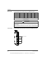
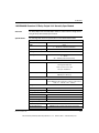
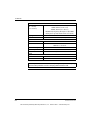
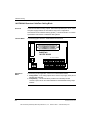
Intrinsically Safe Modules
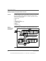
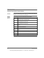
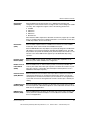
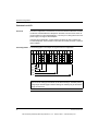
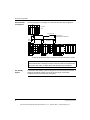
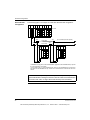
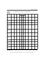
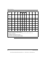
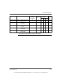
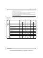
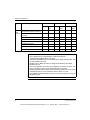
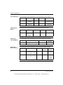
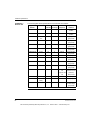
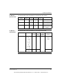
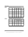
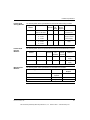
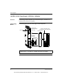
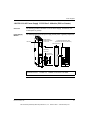
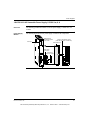
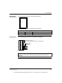
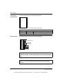
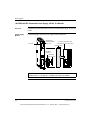
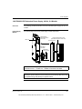
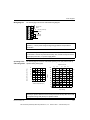
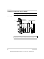
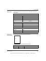
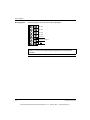
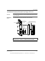
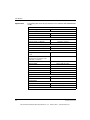
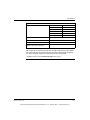
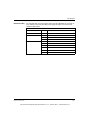
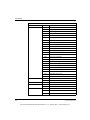
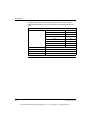
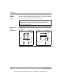
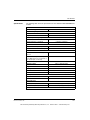
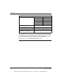
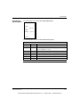
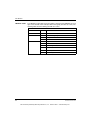
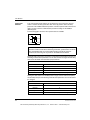
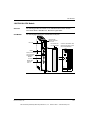
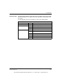
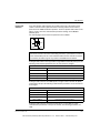
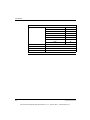
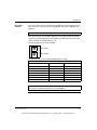
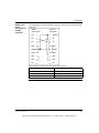
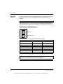
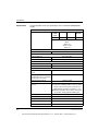
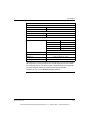
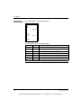
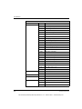
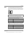
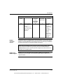
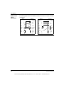
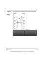
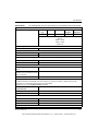
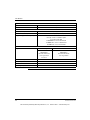
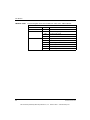
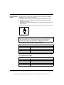
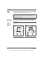
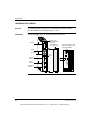
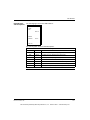
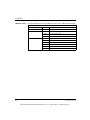
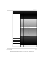
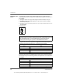
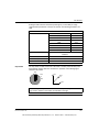
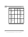
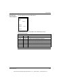
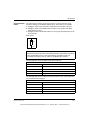
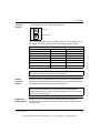
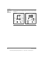
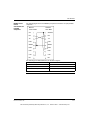
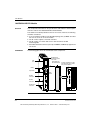
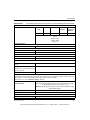
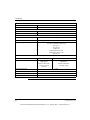
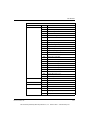
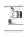
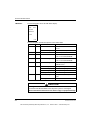
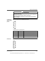
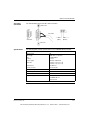
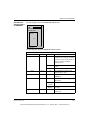
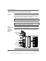
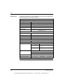
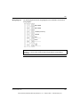
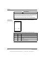
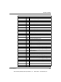
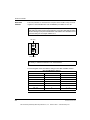
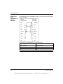
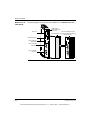
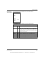
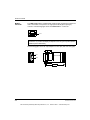
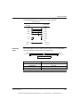
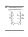
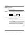
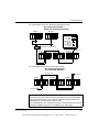
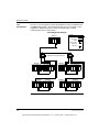
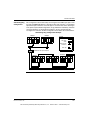
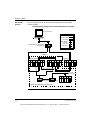
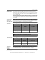
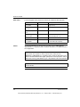
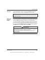
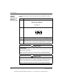
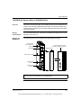
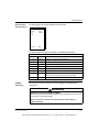
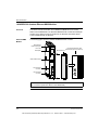
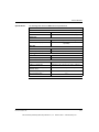
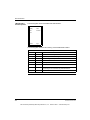
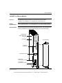
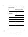
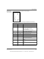
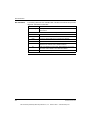
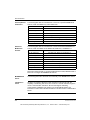
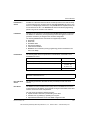
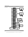
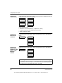
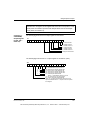
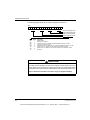
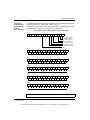
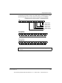
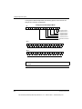
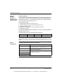
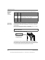
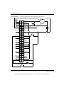
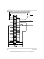
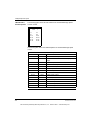
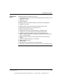
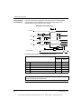
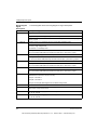
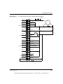
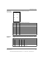
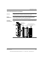
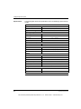
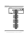
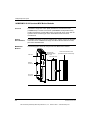
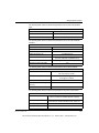
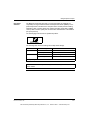
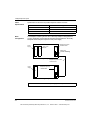
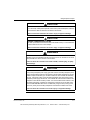
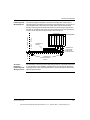
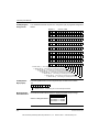
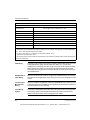
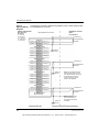
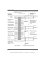
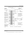
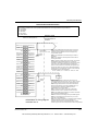
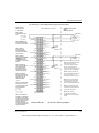
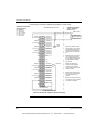
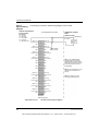
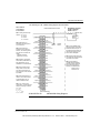
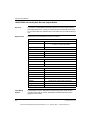
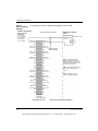
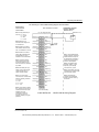
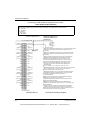
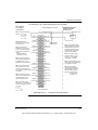
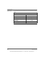
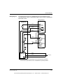
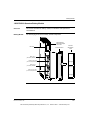
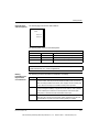
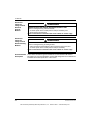
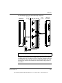
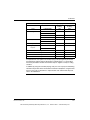
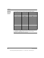
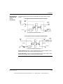
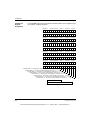
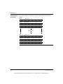
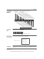
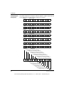
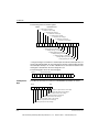
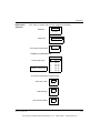
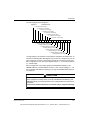
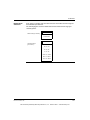
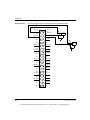
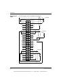
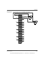
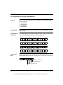
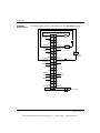
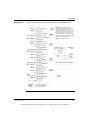
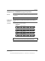
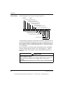
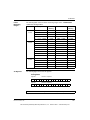
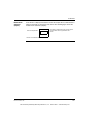
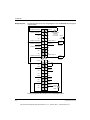
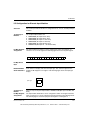
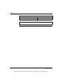
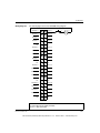
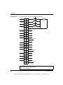
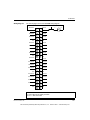
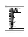
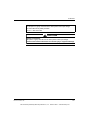
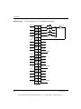
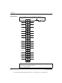
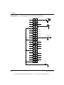
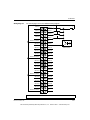
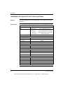
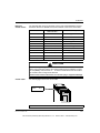
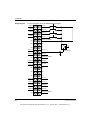
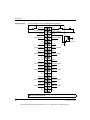
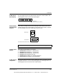
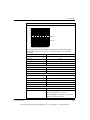
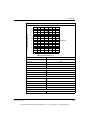
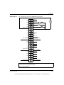
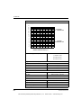
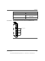
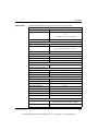
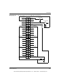
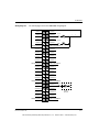
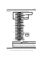
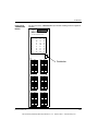
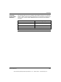
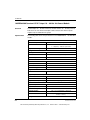
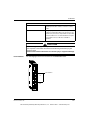
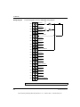
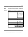
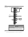
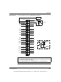
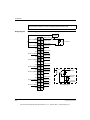
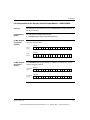
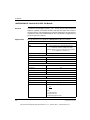
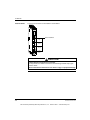
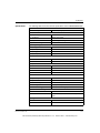
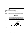
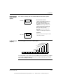
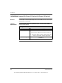
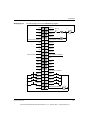
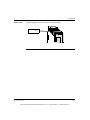
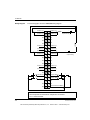
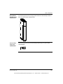
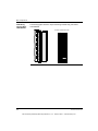
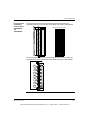
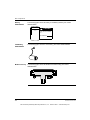
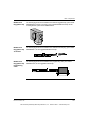
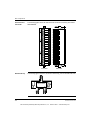
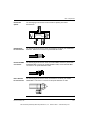
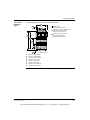
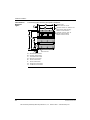
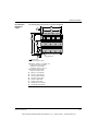
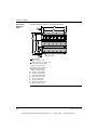
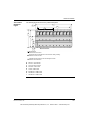
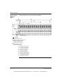
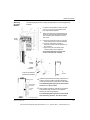
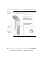
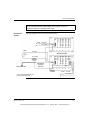
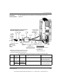
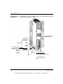
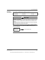
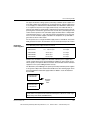
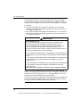
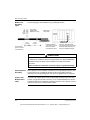
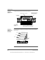
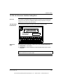
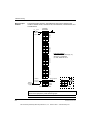
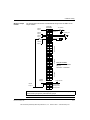
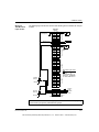
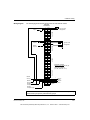
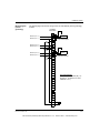
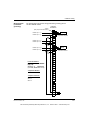
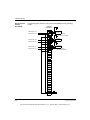
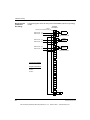
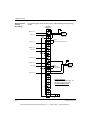
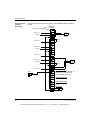
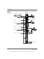
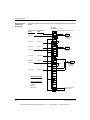
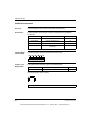
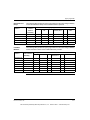
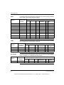
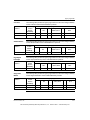
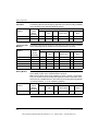
The following is a CSA certified wiring diagram for this module.
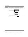
Notes related to
CSA certification
for this module.
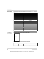
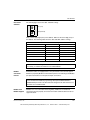
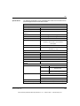
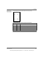
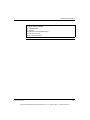
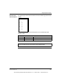
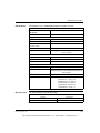
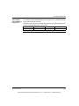
Note 1. Entity
parameters per channel:
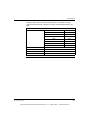
Voc = 23.8 V
Isc = 112 mA
Ca = 127nf
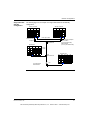
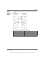
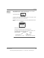
NON-HAZARDOUS LOCATION
(SEE NOTE 1)
V1 (-)
(See Note 2)
N/C
Note 2. Maximum nonhazardous area voltage
must not exceed 250 V.
Note 3. Install in
accordance with
Canadian Electrical
Code, Part I for installation in Canada.
Note 4. Install in
accordance with the NEC
(ANSI/NFPA 70) and
ANSI/ISA RP 12.6 for
installation in the United
States.
Note 5. To maintain
intrinsic safety, shield for
each cable must be
grounded and must
extend as close to the
terminals as possible.
V2 (-)
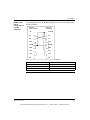
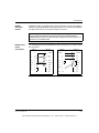
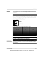
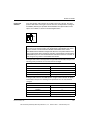
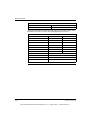
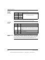
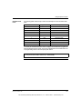
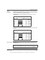
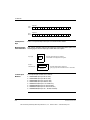
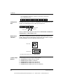
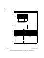
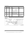
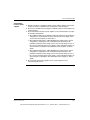
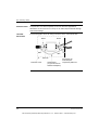
Note 7. I.S. devices when
connected to I.S. terminals must satisfy the following conditions:
Voc < Vmax
Isc < Imax
Ca > Ci + Ccable
La > Li + Lcable
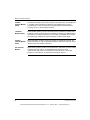
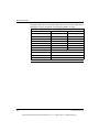
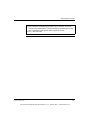
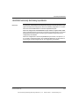
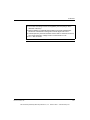
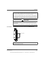
Note 8. This module is
certified as a component
for mounting in a suitable
enclosure where the suitability of the final combination is subject to
acceptance by CSA or an
inspection authority having the jurisdiction.
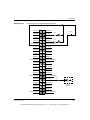
V1 (+)
V2 (+)
Signal 2
N/C
N/C
V3 (-)
N/C
I.S. 3 wire
transmitter
I.S. + 14.5 Vdc
Signal 1
N/C
Chassis
Ground
(See Note 1)
V3 (+)
Signal 3
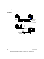
(SEE NOTE 1)
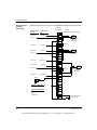
V4 (-)
N/C
N/C
V5 (-)
N/C
V6 (-)
N/C
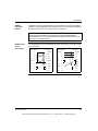
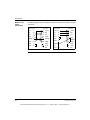
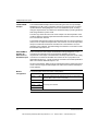
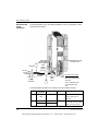
Note 6. intrinsically
Safe (I.S.) cables of one
module must be routed
separately from I.S.
cables of another
module.
HAZARDOUS LOCATION
ZONE 1
GROUP IIA, IIB, IIC
N/C
V7 (-)
N/C
V8 (-)
V4 (+)
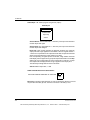
I.S. 2 wire
transmitter
Signal 4
N/C
V5 (+)
Signal 5
Chassis
Ground
(See Note 1)
V6 (+)
Signal 6
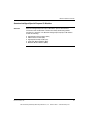
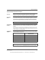
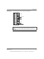
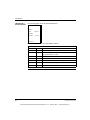
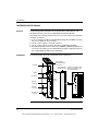
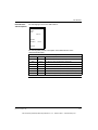
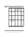
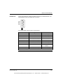
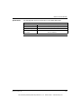
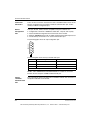
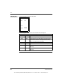
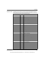
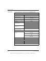
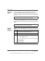
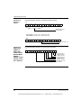
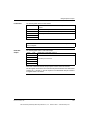
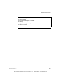
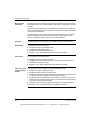
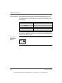
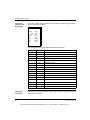
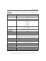
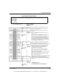
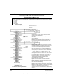
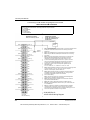
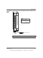
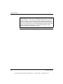
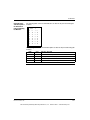
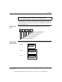
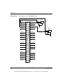
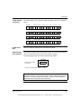
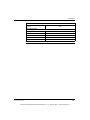
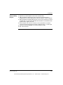
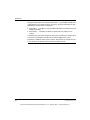
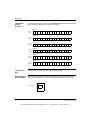
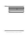
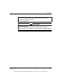
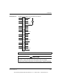
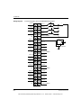
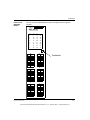
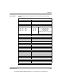
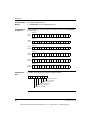
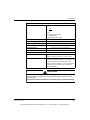
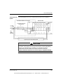
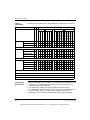
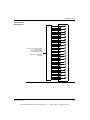
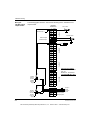
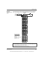
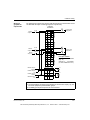
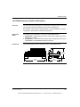
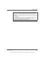
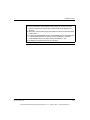
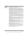
Note 1. Only shielded twisted pair
cables should be used for
connections. Shields should be
left open at the field end and
connected to chassis ground at the
ground screws on the backplane.
Note 2. A dropping resistor 100
Ohms is across the signal and V(-)
pins of each channel. V(-) is
internally connected to I.S. ground.
N/C
V7 (+)
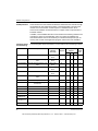
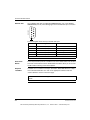
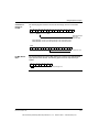
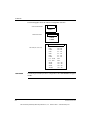
Note 3. Three wire transmitters
should be provided power only
from the module. An external
power supply should not be used.
Signal 7
V8 (+)
N/C
Signal 8
N/C
N/C
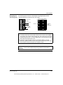
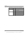
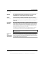
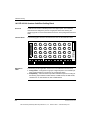
Note 4. Pins marked “N/C” (Not
Connected) are not electronically
connected to the module.
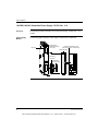
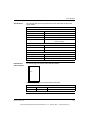
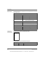
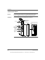
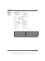
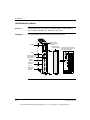
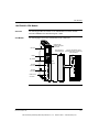
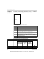
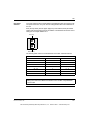
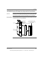
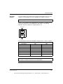
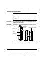
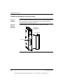
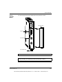
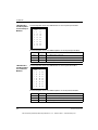
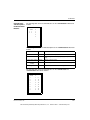
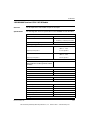
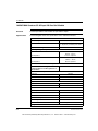
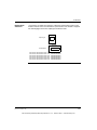
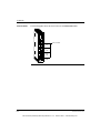
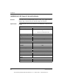
I.S. Module AII 330 10
Blue Terminal Strip
31001363 Rev 00
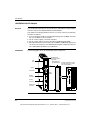
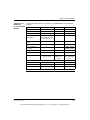
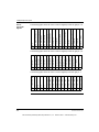
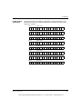
Note 5. Only Quantum
140 XBP 0X 00 backplanes
should be used for mounting this
module.
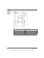
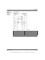
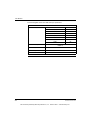
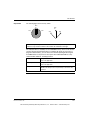
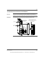
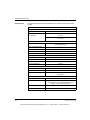
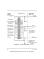
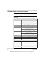
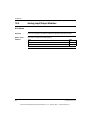
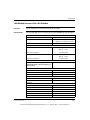
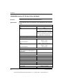
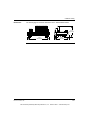
140 AII 330 10 Wiring Diagram
449
35013379 02 October 2007
This document provided by Barr-Thorp Electric Co., Inc. 800-473-9123
www.barr-thorp.com