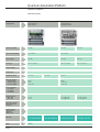
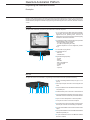
1
For your automation solutions
Modicon Quantum
Opt for performance
1 Quantum Automation Platform
Contents
Modicon Telemecanique
Quantum Automation Platform
CPUs selection guide
pages 1/2 and 1/3
Introduction
pages 1/4 to 1/7
1
Backplanes
140 XBP
pages 1/8 and 1/9
Quantum CPUs
140 CPU
pages 1/10 to 1/13
Power supply selection guide
Power supply modules
pages 1/14 to 1/15
140 CPS
pages 1/16 to 1/21
1/1
Quantum Automation Platform
CPUs
Selection guide
Native operating
system
984 ladder logic (IEC languages require the 16 bit Concept loadable)
On-board
communication ports
1 Modbus
1 Modbus Plus
On-board
math coprocessor
No
On-board processor
clock speed
Intel 186
20 MHz
984 LL performance
(logic solve time)
0.3…1.4 ms/ K ladder logic instructions
IEC 1131-3 program
memory (max)
109 Kbytes
Maximum number of
option interfaces
supported
368 Kbytes
2
Total memory
RAM
Flash
984 LL user logic
Available registers
Extended memory
256 K bytes
256 K bytes
8 K bytes
10 K
None
512 K bytes
256 K bytes
16 K bytes
10 K
None
Model
140 CPU 113 02
140 CPU 113 03
Page
48202/5
0481Q/2
Integrated 984 ladder logic and 32 bit Concept IEC
2 Modbus
1 Modbus Plus
Yes
Intel 486 DX
80 MHz
Intel 586 DX
133 MHz
0.1 ... 0.5 ms/K ladder logic instructions
0.09 ... 0.45 ms/K ladder logic instructions
896 Kbytes
2.5 Mbytes
6
2 M bytes
1 M bytes
64 Kbytes
57 K
96 Kbytes
140 CPU 434 12A
4 M bytes
1 M bytes
64 K bytes
57 K
96 Kbytes
140 CPU 534 14A
48202/5
0481Q/3
Quantum Automation Platform
Introduction
Performance, solutions
Introduction
The Modicon Telemecanique Quantum Automation Series Platform provides the right solution for your control needs with
a full range of high performance, compatible control products. Its architecture is modular and scaleable, so it can be
configured to meet the highest performance requirements for mid-size to large control systems.
Quantum systems combine a very small form factor with industrially rugged designs that ensure cost-effective and reliable
installation in even the most difficult plant environments. The systems are simple to install and configure, and they cover
a wide range of applications.
Performance
With a module depth of only 104 mm (4 inches), including the field wiring, the Quantum Automation Platform represents
a major improvement in panel size requirements. It fits in a standard 156 mm (6 inch) electrical cabinet, saving you up
to 50% over the cost of traditional control panels. It can be mounted easily on a backplane in an industry-standard panel
or rack-mounted in a 500 mm (19 inch) installation.
Within this small form factor, Quantum maintains Schneider's very high standards of product performance and integrity.
The Quantum Platform features:
i Increased system output based on very high scan rates with up to 486- and 586-based processors
i Tightly integrated automation technologies including motion, ASCII, communication and process control
i Redundant power supply and I/O cabling options and true Hot Standby capabilities to provide the highest system
availability for critical applications
i Configurable output fail states for more predictable performance in critical applications
i High levels of isolation for noise immunity in electrically severe environments
i High-accuracy analog I/O for tighter process monitoring and control
i High-speed on/off circuits and interrupt processing for higher system performance
i Hot swapping (the ability to remove and insert I/O modules under power without disturbing other operating elements)
for easier maintenance and increased system availability
A wide range of solutions
Quantum automation solutions can range from a single standalone control system of up to 448 I/O points to a multi-drop,
redundantly serviced network with up to 64 000 I/O points. Connectivity to plant-level and fieldbus networks can be
achieved with communication options that support over eight industry-standard networks, from Ethernet to ASCII.
With advanced Intel-based CPUs, Quantum logic solve
times and I/O throughput rates are fast enough to handle
the high-speed demands of machine control and material
handling. CPU memory sizes range from 256 K bytes to 4
M bytes. Some CPUs are equipped with floating-point
coprocessor chips that solve process algorithms and math
calculations at optimal speeds for process integrity and
quality.
48200/2
Quantum Automation Platform
Introduction
Introduction
(continued)
Programming software
Two popular Schneider Automation programming software packages can be used with Quantum – Concept and Modsoft.
Concept is a Microsoft Windows-based software that complies with all five programming languages specified in the IEC
1131-3 international standard. Concept provides a feature-rich environment where you can rapidly develop structured,
re-usable code. Overall design, startup and maintenance costs are significantly reduced. Concept also supports 984
Ladder Logic programming. You can easily import programs previously developed in a Modsoft environment.
Modsoft is a field-proven DOS-based programming software for the 984 Ladder Logic language. Modsoft provides an
easy step forward for users who want to step up to the improved performance of Quantum while retaining familiarity with
the Ladder Logic environment.
IEC Languages
Software
Features
Function Block Diagram
Concept
Math, bistables, comparators, counters/timers, logic,
edge detection, communications, diagnostics
Sequential Function Chart
Concept
State language approach using steps and transitions
Instruction List
Concept
Boolean instruction set
Structured Text
Concept
High-level text language with Pascal-level instructions
Ladder Diagram
Concept
Discrete contacts, coils and function blocks
Non-IEC Language
Software
Features
984 Ladder Logic
Modsoft or
Concept
984 ladder logic instruction set including contacts, coils,
function blocks, process control, Equation Editor, and
communications
A simple integration path
Ongoing support for our large installed customer base is a commitment we take seriously. The TSX Quantum Automation
Series provides a straightforward and cost-effective integration path for existing 984 and Sy/Max users. The Quantum's
enhanced 984 instruction set allows any Modsoft or translated Sy/Mate application to be executed. In fact, a 584 or 984
program written for existing Modicon controllers will run in a Quantum CPU without any translation required. Quantum
is also backward-compatible with older I/O series that use the Modicon S908 remote I/O network.
Our commitment to simple integration paths can reduce life cycle costs by protecting your investments in software,
hardware and training. Integration of field-proven Ethernet, Modbus and Modbus Plus communication networks is
available for both Quantum and Sy/Max controllers.
Flexible system architectures
No single control architecture can meet all the demands of today's automation market. Some systems are centralized with
local I/O providing the solution. Other systems use a centralized controller with a few drops of remotely mounted I/O. Still
others use many smaller distributed I/O drops along with peer-to-peer communications and integration of fieldbus data.
Using a single I/O family, Quantum can be configured for all of these architectures. It is suitable for process control,
material handling or distributed control.
Quantum is unique in its ability to meet all your automation needs, whatever they may be.
48200/3
Quantum Automation Platform
Introduction
Characteristics
Mecanical characteristics
Weight/module
Dimensions (H x D x W)
Wire size
kg
1.0 max.
lb
2 max
mm
250 x 103.85 x 40.34
inch
9.84 x 4.09 x 1.59
mm
0.5…2.0 one wire, 0.5…1.3 two wires
AWG 14 one wire, 16 two wires, 20 max
Material (chassis and cover)
Space in the backplane
Flame-retardant polycarbonate
slots 1/ module typical, 2 /module for the MMS modules
Electrical characteristics
Electrostatic discharge (IEC 801-2)
air
kV
8
kV
4
RFI immunity (IEC 801-3)
MHz
80…1000, 10 V/m
Ground surge (IEC 801-5)
kV
2, shield-to-ground
contact
Environmental characteristics
Temperature
operating
°C
0…+60
°C
-40…+85
Relative humidity
%
0…95 non-condensing @ 60 °C
Altitude
m
up to 2000, full operation
Shock
G
+/-15 peak for 11 ms, half sine wave
Flammability
V-O
94, connector and module
Free fall
m
1
ft
3
storage
Agency approvals
UL 508
CSA 22.2-142
Factory Mutual, Class I, Div 2
CE
48200/4
Quantum Automation Platform
Introduction
Optional conformal coating
If your control system needs to operate in a corrosive environment, Quantum modules can be ordered with a conformal
coating applied to the cover and bezel. Conformal coating will extend its life and enhance its environmental performance
capabilities.
Mixed flowing gas (power on)
Standard
Pollutant
Parts/billion
Quantum's performance
EIA 364-65
level III
CI2
NO2
20 (+/-5)
200 (+/-50)
H 2S
Meets the standard
Exceeds standard (1250 parts/billion)
100 (+/-20)Meets standard
ISA-S71.04
GX severe
CI2
NO2
H2S
SO2
10
1250
50
300
Exceeds standard (20 parts/billion)
Meets standard
Exceeds standard (100 parts/billion)
Meets standard
Humidity(operating)
Standard
Concentration (%)
Quantum's performance
IEC-68-2-3
93 @ 60 o C
Meets standard
Standard
Concentration (%)
Quantum's performance
IEC 68-2-11
5 (+/-1)
Exceeds standard (5.7%)
Salt mist (non-operating)
Fungus resistance
Standard
Quantum's performance
MIL-I-46058C
Designed to meet standard
Temperature cycling (operating)
Standard
IEC 68-2-14
Cycles
Quantum's performance
o
100 @ 0 ... 60 C
Meets standard
Dust (non-operating)
Standard
Pollutant
Weight (%)
Quantum's performance
EIA 364-TP91
(pending)
silica
calcite
iron oxide
alumina
gypsom
paper fiber
cotton fiber
polyester fiber
carbon black
human hair
cigarette ash
36
29
12
8
5
3
3
2
1
0.5
0.5
Meets
Meets
Meets
Meets
Meets
Meets
Meets
Meets
Meets
Meets
Meets
standard
standard
standard
standard
standard
standard
standard
standard
standard
standard
standard
Availability
All Quantum backplanes, power supplies, I/O modules, special-purpose modules and CPUs are available as conformally
coated modules. Almost all the Quantum communication adapters are available as conformally coated modules–the only
exceptions is the Echelon 140 NOL 911 10 LonWorks option modules.
How to order conformally coated modules
To order a Quantum module or backplane with conformal coating applied, simply append a C to the standard model
number. For example, if you want to order a 140 CPS 114 00 Power Supply with conformal coating, the new model number
is 140 CPS 114 00C. For more information about conformally coated Quantum modules, contact your distributor or
regional sales office.
48200/5
Quantum Automation Platform
Backplanes
Presentation, description
Presentation
The Modicon TSX Quantum modules mount easily into backplanes in industry-standard electrical cabinets or on19-inch
racks. Optional mounting brackets are available for rack-mounting. A backplane provides the control signals and
distributes the power necessary operate the installed modules.
Description
Six different backplane models are available (with 2, 3, 4, 6, 10, or 16 slots. Backplane slots are universal) in other words,
any module may fit into any slot. Almost all Quantum modules are designed to fit into single slots on a Quantum backplane;
the only exception is the MMS SERCOS motion module, which requires two contiguous slots.
There are no slot dependencies in a Quantum system, although we do recommend that power supply modules use the
outermost slot position for optimum heat dissipation. The only limits on the backplane are available module power and
addressing space. Any backplane may be used in any of the three system architectures supported by Quantum
(standalone with local I/O, remote I/O or distributed I/O). Your service inventory can be reduced because there are no
special backplanes for different I/O architectures.
In a Quantum system, all module addressing and configuration are handled by panel software. There are no DIP switches
or other hardware settings required.
4
1 Metal frame.
2
2 Backplane connector.
3 Tapped holes for affixing modules.
1
5
3
4 Mounting holes.
5 Grounding terminals.
Backplane Expander Module
The 140 XBE 100 00 Quantum Backplane Expander module allows I/O in an adjacent, “secondary” backplane to
communicate with the CPU or RIO drop adapter in the “primary” backplane over a custom communications cable. A
Backplane Expander module must be installed in each backplane. The expander cable provides all the signals required
to accomplish data communication between the two backplanes. Only a single Backplane Expander module can be added
to each backplane.
The Backplane Expander module features the following flexible characteristics:
i The same 140 XBE 100 00 Backplane Expander modules are used for the primary and secondary backplanes.
i The system can use any type of Quantum power supply. Each backplane can have a different type of power supply.
i Loss of power in the secondary backplane will not shut down the entire drop. Only modules located in the secondary
backplane will lose power.
i Backplane Expander modules can be located in any slot in the backplane, and do not have to be placed in
corresponding slots in the primary and secondary backplanes.
i The Backplane Expander module will not be recognized by the programming panel software. It appears as an unfilled
slot in the I/O map.
48201/2
Quantum Automation Platform
Backplanes
References, dimensions
References
Description
Number of
slots
Reference
Weight
kg (lb)
Racks for:
Local I/O modules
Remote I/O modules
Distributed I/O modules
2
140 XBP 002 00
0.230 (0.5)
3
140 XBP 003 00
0.340 (0.75)
4
140 XBP 004 00
0.450 (1.0)
6
140 XBP 006 00
0.640 (1.4)
10
140 XBP 010 00
1.000 (2.2)
16
140 XBP 016 00
1.600 (3.5)
Backplane accessories
Description
Dimensions
Reference
Backplane expander
–
140 XBE 100 00
–
Backplane expander cables
1m
140 XCA 717 03
–
2m
140 XCA 717 06
–
3m
140 XCA 717 09
–
19 in front rail mounting bracket
for 140 XBP 010 00
125 mm (4.92 in)
depth
140 XCP 401 00
–
19 in rear rail mounting bracket
for 140 XBP 010 00
20 mm (0.79 in)
depth
140 XCP 402 00
–
Weight
kg (lb)
Dimensions
140 XBP 0i0 00
Front view
290
102
143
6 slots
290
4 slots
290
3 slots
290
2 slots
184
428
290
16 slots
290
10 slots
265
671
Depth with modules: 104 mm
48201/3
Quantum Automation Platform
CPUs
Presentation
Presentation
The Quantum CPUs are single-slot programmable controllers with built-in executive memory, application memory and
communication ports. With all memory components on-board, you do not need extra chips or cartridges for configuration.
Flash-based executive memory
Quantum CPUs use flash memory technology to support the CPU's executive memory and instruction set. Flash is a stateof-the-art, nonvolatile memory technology that enables field upgrades by downloading files over the Modbus or Modbus
Plus port as new features and maintenance updates become available.
Memory backup and protection
The CPUs store the application program in battery-backed RAM. The battery is located on the front of the module and
can be serviced while the CPU is running. To protect the application program from inadvertent changes during operation,
the CPUs feature a memory-protect slide switch. An LED goes on when this switch is activated.
Math coprocessor hardware support
For math-intensive applications, Quantum offers math coprocessor hardware on select CPU models. The coprocessor
significantly improves execution times for the 984 Process Control Function Library (PCFL) and Equation Editor as well
as math operations in the IEC languages. Improved floating point execution times mean more accurate performance for
process algorithms and math calculations.
Write protection
Controller write protection minimizes the possibility of a programmer inadvertently writing from a source controller to a
memory area in a destination controller that has been reserved for internal operations. The programming software sets
up an enabled area in the CPU for coil access and data references from across the network. Whatever data is not enabled
is prevented from writing references, both locally and over the network. This data fence option provides excellent security
against data transfer errors, creating a simple and effective communications firewall.
Communication ports
All CPUs support Modbus and Modbus Plus networking strategies. Simple rotary switches on the back of the modules
are used to set the network address of the Modbus Plus port(s). Each device on a Modbus Plus network must have a
unique address in the range 1…64. Modbus port settings include baud, parity, number of data bits, number of stop bits,
protocol and drop address. By default, these settings are 9600 baud, even parity, 8 data bits, 1 stop bit, RTU mode and
address 1. A slide switch on the front of the CPU can reset the Modbus port parameters to an alternative power-up mode
that supports modem communications–2400 baud, even parity, 7 data bits, 1 stop bit, ASCII mode and address 1.
48202/2
Quantum Automation Platform
CPUs
Description
Description
1
1 Model number and color code
2 LED array
3 Removable, hinged door and customer identification
label
4 Battery
5 Micro switches
6 Modbus port A
7 Modbus Plus port B
8 Modbus Plus port
2
3
4
Note:
The 140 CPU 113 0x CPUs have one Modbus and one
Modbus Plus communication ports.
5
6
7
8
Slide switches
Each of the two slide switches has three-position functionality:
The left slide switch activates the memory write-protect. In
the upper position, write protection is enabled; in the middle
position, write protection is disabled.
mem prt
ASCII
off
RTU
mem
not used
The right slide switch determines the startup communication parameters for the Modbus port. The middle position,
RTU, is the factory-set default. The upper position, ASCII,
is for modem communications. If you need to set special
startup parameters for the Modbus port–for example, if
your Modbus address is not 1–you can set applicationspecific parameters in memory and set the slide switch in
the bottom position.
Language choices
Advanced IEC 61131-3 Languages
Quantum's 5 IEC 61131-3 languages are:
i Sequential Function Chart: provides overall structure and coordination for batch oriented process of machine control
applications.
i Function Block Diagram: particularly well suited for process control applications.
i Ladder Diagram: excellent for discrete control and interlocking logic.
i Structured Text: higher level language which is a terrific solution for complex algorithms and data manipulation.
i Instruction List: low level language for optimized code performance.
984 Ladder Logic
A high performance, low level language whose application source code resides in the controller.
A full set of over 80 instructions are included with every Quantum CPU. The 984 instruction set ensures compatibility and
easy integration paths for installed Modicon applications, including:
i Immediate I/O and interrupt servicing to enhance system performance.
i Equation editor for easier match capabilities.
48202/3
Quantum Automation Platform
CPUs
Characteristics
Characteristics
Model
140 CPU 113 02
140 CPU 113 03
140 CPU 434 12A
140 CPU 534 14A
Processor
80186
80186
80486
80586
Math coprocessor
No
No
Yes
Yes
20
20
66
133
Clock speed
User logic
MHz
max. IEC program
words 109 K
368 K
896 K
2.5 M
984 ladder logic
words 8 K
16 K
64 K
64 K
bits
8192 in/8192 out
64 K any mix
64 K any mix
Reference capacity
discretes
8192 in/8192 out
registers
words 9999 max
9999 max
57 K max
57 K max
extended memory
words –
–
96 K
96 K
0.3…1.4
0.1…0.5
0.9…0.45
Logic solve time (984 LL instructions) ms/k
0.3…1.4
Watchdog timer
ms
250 (software-adjustable)
TOD clock accuracy
s/day +/-8@ 0…60 °C
Local I/O
Maximum I/O words
64 I/64 O
Remote I/O (RIO)
I/O words/drop
64 I/64 O
number of drops
31
number of networks
3
Distributed I/O (DIO)
I/O words/drop
Battery
45°C
30 I/32 O
I/O words/network
500 I/500 O
drops/networks
63
number of networks
1
type
lithium
service life
mAh
1200
lifetime
yrs
10
load current, typical
µA
5
7
7
14
load current, max
µA
110
210
210
420
1
1
2
2
1
1
1
1
Maximum number of NOM,
NOE, CRP, MMS modules supported
2
2
6
6
Key switch
No
No
Yes
Yes
780
790
1800
1800
Communication ports
Modbus (RS 232)
Modbus Plus
Required bus current
48202/4
mA
Quantum Automation Platform
CPUs
References
References
Memory
Co-processor
Reference
256 K bytes
No
140 CPU 113 02
0.300 (0.66)
512 K bytes
No
140 CPU 113 03
0.300 (0.66)
2 M bytes
integrated
140 CPU 434 12A
0.850 (1.87)
4 M bytes
integrated
140 CPU 534 14A
0.850 (1.87)
Length
m (ft)
Reference
3.7 (12)
990 NAA 263 20
0.300 (0.66)
15 (50)
990 NAA 263 50
1,820 (4.0)
Battery for CPU
–
990 XCP 980 00
–
Quantum automation series
hardware reference guide
–
840 USE 100 0X
–
Accessories
Description
Programming cable for
Modbus interface
Weight
kg (lb)
Weight
kg (lb)
48202/5
Quantum Automation Platform
Power supply modules
Selection guide
Type
Standalone
Input voltage
c 100…276 V
a 20…30 V
Frequency
47…63 Hz
–
Input current
0.4 A @ c 115 V
02 A @ c 230 V
1.6 A
Output current
3.0 A max.
0.3 A min.
External fusing
1.5 A slow-blow
2.5 A medium time lag
0.75 A slow-blow
2.0 A slow-blow
Maximum power
interruption
8 ms
20 ms
1 ms
8 ms
Alarm relay
contact
No
Model
Page
0479Q/2
Summable
a 100…150 V
c 93…138 V or
c 170…276 V
47…63 Hz
0.4 A
1.1 A @ c 115 V
0.6 A @ c 230 V
8.0 A @ 60o C
140 CPS 111 00 140 CPS 211 00 140 CPS 511 00 140 CPS 114 10
48203/7
Summable
a 20…30 V
Redundant
a 48…60 V
c 93…138 V or
c 170…276 V
a 20…30 V
–
47…63 Hz
–
3.8 A max.
1.1 A @ c 115 V
0.6 A @ c 230 V
3.8 A max.
8.0 A
8.0 A @ 60o C
8.0 A
a 48…60 V
a 100…150 V
0.5 A @ a 125 V
5.0 A slow-blow
2.0 A medium time lag
2.0 A slow-blow
5.0 A slow-blow
2.0 A medium time lag
2.0 A slow-blow
1 ms
13 ms
8 ms
1 ms
13 ms
1 ms
No
Yes
Yes
No
140 CPS 214 00 140 CPS 414 00 140 CPS 124 00 140 CPS 224 00 140 CPS 424 00 140 CPS 524 00
0479Q/3
Quantum Automation Platform
Power supply modules
Presentation, characteristics
Presentation
Quantum power supply modules serve two purposes–they provide power to the system backplane and protect the system
from noise and nominal voltage swings. All power supplies feature over-current and over-voltage protection. They operate
in most electrically noisy environments without the need for external isolation transformers. In the event of an unforseen
loss of power, the power supplies ensure that the system has adequate time for a safe and orderly shutdown.
A power supply converts the incoming power source to a regulated +5 V d.c. to support the CPU, the local I/O and any
communication option modules mounted in the backplane. Power between the field sensors/actuators and the Quantum
I/O points is not provided by these power supply modules.
If your Quantum system is being used in a standalone (local I/O) or remote I/O control architecture, three types of power
supplies are available:
i Low-power standalone power supplies.
i High-power summable power supplies.
i High-power redundant power supplies.
If your Quantum system is being used in a distributed I/O architecture, special low-power standalone power supplies,
which are dedicated to distributed architectures and are integrated into distributed I/O adapter modules, are available.
Distributed power supplies are described in the DIO architecture section of this catalog.
Characteristics of the power supply types
Standalone power supplies
A standalone power supply delivers 3 A of power to a Quantum backplane.When your control system has low-power
requirements, a standalone power supply is an economical choice. Standalone supplies are available for115/230 V a.c.,
24 V d.c.and 125 V d.c. source voltages.
Summable power supplies
A summable power supply delivers 8 A of power to a Quantum backplane. Summable supplies can operate in either a
standalone or summable mode. Whenever two summable supplies are combined in the same backplane, they
automatically operate in summable mode–delivering 16 A of power to the backplane. In summable mode, the two supplies
must be the same model and they should be placed in the left and right edge slots of the backplane for maximum life. If
one of the two supplies fails, power is lost to the backplane.
If only one summable power supply is placed in a backplane, it functions in standalone mode–delivering 8 A to the
backplane.
Summable power supplies are available for 115/230 V a.c., 24 V d.c. and 48/60 V d.c. source voltages.
Redundant power supplies
A redundant power supply delivers 8 A of power to a Quantum backplane. For high-availability applications, two redundant
power supplies in a backplane deliver 8 A of redundant power. In the event that one supply fails, the healthy one maintains
the necessary power so that backplane processing and active communications are not affected. Each redundant supply
has a status bit that can be monitored by the CPU's application program or by a supervisory system so that you can
respond quickly in the event of a power supply failure.
If additional power is required in a redundant power supply configuration, a third redundant supply module can be added
to the backplane - increasing the total redundant power capacity to 16 A. Should one of the three supplies fail, the two
healthy modules will revert to the standard redundant mode–delivering 16 A of redundant power to the backplane.
A single redundant power supply module may be used as a standalone supply if you need to reduce your stockroom
requirements.
Redundant power supplies are available for 115/230 V a.c., 24 V d.c., 48/60 V d.c. and 125 V d.c. source voltages.
48203/2
Quantum Automation Platform
Power supply modules
Description
Description
1
1 Model number and color code
2 LED array
3 Removable, hinged door and customer identification
label
4 Terminal block
2
3
4
Temperature range
The bus current has a guaranteed minimum value valid for
the entire temperature range (up to 60 °C). This chart, for
a 140 CPS 114 10 standalone V a.c. supply, shows that a
power supply module can provide significantly more power
at lower temperatures.
I (A)
12
10
8
6
4
2
40
45
50
55
60
Ambient temperature (°C)
Maximum power interruption
Time
ms
100
100
68
Capacitor size (mF)
47
90
80
22
The buffer processing times for the CPS 214 00,
CPS 224 00, CPS 414 00, and the CPS 424 00 power
supplies can be increased by adding V d.c. electrolytic
capacitors at terminals 5 and 6. Respective capacitor
ratings are shown in this diagram.
70
60
50
40
30
10
5.8
4.7
2.2
1
0
20
10
0
20 21 22 23 24 25 26 27 28 29 30
Input voltage (V)
48203/3
Quantum Automation Platform
Power supply modules
Characteristics
Characteristics for V a.c. and V d.c. source voltages
Model
Input Requirements
Input voltage
Input frequency
Input current
@ c 230 V
@ c 115 V
Inrush current
@ c 230 V
@ c 115 V
Rating
External fusing
Input power
Interruption
Harmonic distortion
140 CPS 111 00 (1)
140 CPS 114 10 (2)
140 CPS 124 00 (3)
cV
Hz
100…276
47…63
93…138 or 170…276
47…63
93…138 or 170…276
47…63
A
A
0.2
0.4
0.6
1.1
0.6
1.1
A
A
VA
A
20
19
10
38
50
130
1.5 slow-blow
2.0 slow-blow
1/2 cycle @ full load and minimum line voltage/frequency, and
less than 1 s between interrupts
Less than 10 of fundamental rms value
19
38
130
2.0 slow-blow
%
Output-to-bus Voltage
Current
Protection
a V
A
5.1
3 max, 0.3 min
Over-current, over-range
5.1
8 @ 60 oC
5.1
8 @ 60 oC
General
W
2.0 + (3 x I OUT)
where IOUT is in A
6.0 + (1.5 x I OUT)
where IOUT is in A
6.0 + (1.5 x I OUT)
where IOUT is in A
140 CPS 211 00 (1)
140 CPS 214 00 (2)
140 CPS 224 00 (3)
a V
A
A
a V
ms
20…30
1.6
30
–
1.0 @ a 20 V
20.0 @ a 25 V
20…30
20…30
3.8 max
3.8 max
25 @ a 24 V, 14 @ a 20 V
25 @ a 24 V, 14 @ a 20 V
94…189 Hz
94…189 Hz
1.0 @ a 20 V
1.0 @ a 20 V
100 ms maxi with external condensateur
A
2.5 slow-blow
5.0 slow-blow
Output-to-bus Voltage
Current
Protection
a V
A
5.1
3 max, 0.3 min
Over-current, over-range
5.1
8.0
General
Surge withstand
a V
–
Internal power
dissipation
Alarm relay
W
2 + (3 x IOUT), where IOUT is A
6 + (1.8 x IOUT), where IOUT is A
N
Y
Internal power
dissipation
Module Type
requirements
Module Type
Input
requirements
Input voltage
Input current
Inrush current
Input ripple
Input power
Interruption
External fusing
(recommended)
2.3 x max rated input voltage
for 1.3 ms
140 CPS 414 00 (2)
140 CPS 424 00 (3)
140 CPS 511 00 (1)
140 CPS 524 00 (3)
Input voltage
a V
48…60
48…60
100…150
100…150
Input current
A
3.8 max
3.8 max
0.4
0.5 @ a 125 V
Inrush current
Input power
interruption
External fusing
(recommended)
A
ms
14 @ a 40 V
13.0 @ a 48 V
14 @ a 40 V
13.0 @ a 48 V
10
1.0 max
28 @ a 125 V
1.0 max
A
2.0, medium time lag
2.0, medium time lag
3/4 slow-blow
2 slow-blow
Output-to-bus Voltage
Current
Protection
a V
A
5.1 V
8.0
Over-current, over-range
5.1 V
8.0
5.1 V
3 max, 0.3 min
5.1 V
8.0
General
W
15.6 @ 8 A
17.2 @ 8 A
2 + (3 x IOUT)
where IOUT is A
6 + (1.5 x IOUT)
where IOUT is A
Y
Y
N
N
Internal power
dissipation
Alarm relay
Device Type : (1) standalone, (2) summable, (3) redundant.
48203/4
Quantum Automation Platform
Power supply modules
References, wiring
References
Power supplies
Input Voltage/Power
Type
Reference
c 120/230 V, 3 A
Standalone
140 CPS 111 00
0.650 (1.43)
c 120/230 V, 8 A
Summable
140 CPS 114 10
0.650 (1.43)
c 120/230 V, 8 A
Redundant
140 CPS 124 00
0.650 (1.43)
a 24 V, 3 A
Standalone
140 CPS 211 00
0.650 (1.43)
a 24 V, 8 A
Summable
140 CPS 214 00
0.650 (1.43)
a 24 V, 8 A
Redundant
140 CPS 224 00
0.650 (1.43)
a 48 ... 60 V, 8 A
Summable
140 CPS 414 00
0.650 (1.43)
a 48 ... 60 V, 8 A
Redundant
140 CPS 424 00
0.650 (1.43)
a 125 V, 3 A
Standalone
140 CPS 511 00
0.650 (1.43)
a 125 V, 8 A
Redundant
140 CPS 524 00
0.650 (1.43)
IP20 rated
140 XTS 001 00
0.150 (0.33)
Weight
kg (lb)
Accessories
Power connector
External wiring
140 CPS 114 10
140 CPS 114/124 00
140 CPS 111 00
1
X
1
X
2
X
2
X
3
X
3
X
4
X
4
X
5
X
5
X
6
X
6
X
7
X
7
X
a.c.L
a.c.N
}
140 CPS 211 00
Internally
connected. Do
not wire
externally.
1
X
1
X
2
X
2
X
Install jumper
(for c 115 V only)
3
X
3
X
4
X
4
X
5
X
5
X
6
X
6
X
7
X
7
X
a.c.L
a.c.N
s
-24 V d.c. (common)
+24 V d.c.
s
140 CPS 414/424 00
1
X
2
X
3
X
4
X
5
X
6
X
7
X
}
Power loss alarm
-48 ... -60 V d.c.
(common)
+48 ... +60 V d.c.
+
_
140 CPS 214/224 00
Capacitor
(optional)
s
}
Power loss alarm
-24 V d.c. (common)
+24 V d.c.
+
Capacitor
(optional)
_
s
140 CPS 511 00
s
140 CPS 524 00
1
X
1
X
2
X
2
X
3
X
3
X
4
X
4
X
5
X
6
X
7
X
5
X
6
X
7
X
+ 125 V d.c.
- 125 V d.c.
(common)
s
}
Internally
connected. Do
not wire
externally.
+ 125 V d.c.
- 125 V d.c.
(common)
s
48203/5
2 Discrete I/O
Contents
Discrete I/O
Discrete I/O selection guides
Discrete I/O modules
pages 2/2 to 2/11
i
140 DAi
i
140 DDi
i
140 DRi
pages 2/12 to 2/33
Cablefast wiring system
Telefast 2 pre-wired system
2
ABE-7i
i
ABR-7S
i
ABS-7i
ABC-6HE
pages 2/36 to 2/41
2/1
Quantum Automation Platform
Discrete I/O
V d.c. input modules
Selection guide
Type
a
Input Voltage
5 V/TTL
Number of Points
32
Number of Groups
4
Points/Common
8
Isolation
by group
Addressing
Requirements
2 input words
24 V
Bus Power
Required
170 mA
330 mA
Logic
Source
Sink
Source
Model
140 DDI 153 10
140 DDI 353 00
140 DDI 353 10
Page
48204/22
0482Q/2
a
24 V
125 V
10…60 V
20…30 V
96
24
16
32
6
3
8
8
4
16
8
2
4
8
6 input words
2 input words
1 input word
2 input words
4 input words
270 mA
200 mA
300 mA
250 A
140 DDI 853 00
140 DSI 353 00
Sink
140 DDI 364 00
140 DDI 673 00
140 DDI 841 00
0482Q/3
Quantum Automation Platform
Discrete I/O
V a.c. input modules
Selection guide
Type
c
Input Voltage
24 V
Number of Points
16
32
16
32
Number of Groups
16
4
16
4
Points/Common
1
8
1
8
Isolation
individual points
by group
individual points
by group
Addressing
Requirement
1 input word
2 input words
1 input word
2 input words
Bus Power
Required
180 mA
250 mA
180 mA
250 mA
Model
140 DAI 340 00
140 DAI 353 00
140 DAI 440 00
140 DAI 453 00
Page
48204/22
0482Q/4
48 V
c
115 V
230 V
16
32
16
32
4
16
4
16
2
1
8
1
8
individual points
by group
individual points
by group
1 input word
2 input words
1 input word
2 input words
180 mA
250 mA
180 mA
250 mA
140 DAI 540 00
140 DAI 543 00
140 DAI 553 00
140 DAI 740 00
140 DAI 753 00
0482Q/5
Quantum Automation Platform
Discrete I/O
V d.c. and relay output modules
Selection guide
Type
a
Output voltage/
Relay type
5 V/TTL
Number of points
32
96
Number of groups
4
6
Points/common
8
16
Maximum load
Current /point
Current /group
Current /module
25 mA
600 mA
2.4 A
Addressing
requirement
2 output words
24 V
19.2…30 V
.5 A
4A
16 A
0.25 A
6 output words
Bus power
required
350 mA
330 mA
Logic
sink
source
sink
source
Module
140 DDO 153 10
140 DDO 353 0i
140 DDO 353 10
140 DDO 364 00
Page
48204/22
0483Q/2
250 mA
a
Relay
10 ... 60 V source
24 ... 125 V source
10…30 V
Normally open
Normally open/
Normally closed
16
12
32
16
8
2
6
4
16
8
8
2
8
1
2A
6A
12 A
0.75 A
3A
6A
0.5 A
4A
16 A
2A
N/A
N/A
5A
N/A
N/A
1 output word
1 input word
1 output word
2 output words
1 output word
0.5 output word
160 mA
375 mA @ 6 points on
650 mA @ 12 points on
500 mA
1100 mA
560 mA
140 DDO 885 00
140 DVO 853 00
140 DRA 840 00
140 DRC 830 00
48204/16
48204/16
48204/22
source
140 DDO 843 00
0483Q/3
Quantum Automation Platform
Discrete I/O
V a.c. output modules
Selection guide
Type
c
Output voltage
24 ... 230 V
Number of points
16
Number of groups
16
Points/common
1
Maximum load
Current /point
Current /group
Current /module
4 A @ 20-132 VAC, 8 A @ 170-253 VAC
N/A
16 A
Addressing
requirement
1 output word
Bus power
required
4 A @ 20-132 VAC
N/A
16 A
350 mA
Module
140 DAO 840 00
Page
48204/22
0483Q/4
24 V ... 115 V
140 DAO 840 10
c
100 ... 230 V
24 ... 48 V
24 ... 230 V
32
4
4
4 A @ 20-132 VAC, 8 A @ 170-253 VAC
4A
16 A
8
4 A @ 20-56VAC
4A
16 A
1A
4A
16 A
2 output words
320 mA
140 DAO 842 10
140 DAO 842 20
140 DAO 853 00
0483Q/5
Quantum Automation Platform
Discrete I/O
V a.c. input/output modules
Selection guide
Output voltage
c 85...132 V
a 19.2...30 V
Input voltage
c 132 V
a 30 V
Number of points
16 input / 8 output
Number of groups
Two 8-point inputs
Two 4-point outputs
Maximum load
current/point
current/group
current/module
4A
4A
8A
Addressing
requirement
1 input word
0.5 output word
Bus power
required
250 mA
330 mA
Model
140 DAM 590 00
140 DDM 390 00
Page
48204/22
0483Q/6
15 A
2A
4A
a 19.2...156.2 V
a 156.2 V
4 input, 4 isolated output
One 4 point inputs
Four output points
4A
N/A
16 A
1 input word
1 output word
350 mA
140 DDM 690 00
0483Q/7
Quantum Automation Platform
Discrete I/O
General, description
The Modicon TSX Quantum Automation Series supports a full range of discrete I/O modules designed to interface with
a wide variety of field devices. All modules meet internationally accepted IEC electrical standards that ensure reliability
in harsh operating environments. For even better protection and extended life in extremely harsh environments, you can
have your modules conformally coated.
Fully software-configurable
All Quantum I/O modules can be completely configured using Concept or Modsoft. The ability to specify an I/O address
for each module in software makes it easy to add or change modules in your configuration without physically changing
the application program.
Defining the failure mode of an output module
Quantum gives you the ability to predefine how a discrete output point will respond if for any reason the module stops being
serviced. You can configure the module in software so that the outputs:
i Turn off
i Go to a predefined safe state
i Hold the last value they received before the watchdog timer expired
Failure modes can be defined on a point-by-point basis. In the event of a complete module failure, the fail state settings
you have specified can be sent to the replacement module.
Mechanical keying for added security
Optionally, you can insert mechanical keys between the I/O module and the terminal strip to ensure that the field wiring
and the module type are properly matched. Keying codes are unique for each module type. You can also implement
mechanical keying for unique slot locations so that a rack full of similar modules with similar keying codes will not be
incorrectly connected. Keys are shipped with the I/O modules. They do not need to be ordered separately.
I/O connectors
Each I/O module requires an I/O connector (P/N 140 XTS 002 00), which can be ordered separately. The same connector
can be used with all modules.
Description
1
2
3
4
48204/2
1 Model number and color code.
2 LED indicator panel.
3 Removable, hinged door and customer identification
label.
4 Terminal block.
Quantum Automation Platform
Discrete I/O
Sample LEDs
Visual status and diagnostic information
Extensive LED information is available on each module. Information includes activity on the I/O points and specific module
features such as field wiring fault indication and blown fuses. Visual indication of comunication health is provided on an
Active display, which can be used for troubleshooting.
32-point discrete I/O modules
1
2
3
4
5
6
7
8
Active
F
9
10
17
25
18
19
26
27
20
28
29
11
12
13
14
21
22
15
23
24
16
LED
Color
Indication when on
Active
F
1…32
green
red
green
Bus communication is present
External fault detected
The respective input/output is
turned on
LED
Color
Indication when on
Active
green
Bus communication is present
been detected
A fault (external to the module) has
been detected
The indicated point or channel is
turned on
There is a fault on the indicated point
or channel
30
31
32
16-Point discrete I/O modules
1
Active
9
1
F
9
2
10
2
10
F
red
3
11
3
11
1 ... 16
green
4
12
4
12
5
13
5
13
1 ... 16
red
6
14
6
14
7
15
7
15
8
16
8
16
Discrete Bi-directional modules
1
2
Active
F
1
2
1
2
3
4
LED
Color
Indication when on
Active
F
green
red
1 and 2
left row
1 and 2
middle row
1…4
right row
green
Bus communication is present
No voltage supply for outputs or
inputs out of tolerance
Output is turned on
red
Fault detected on the output point
red
Fault detected on the input point
48204/3
Quantum Automation Platform
Discrete I/O
Characteristics
V a.c. input specifications
Model
140 DAI 540 00
140 DAI 543 00
140 DAI 553 00
140 DAI 740 00
140 DAI 753 00
Number of inputs
16
16
32
16
32
Number of groups
16
2
4
16
4
Inputs/group
1
8
8
1
8
c
Input voltage
LEDs
115 V
230 V
Active
1…16 (green)
Active
1…16 (green)
Active
1…32 (green)
Active
1…16 (green)
Active
1...32 (green)
words
1 input
1 input
2 input
1 input
2 input
c
175…264 V
0...40 V
9.7 max
31.8 capacitive
165...264 V
0...40 V
11.5 max
26.5 capacitive
170...264 V
0...40 V
2.6 max
32
158...264 V
0...40 V
mA
kΩ
85…132 V
0...20 V
11.1 max
14.4 capacitive
79…132 V
0...20 V
13.2 max
12 capacitive
Frequency range
Hz
47…63
Maximum leakage current
mA
2.1
2.6
c
132 V
156 V
200V
264 V
300 V
400 V
264 V
312 V
400 V
ms
4.9
0.75 x line cycle
7.3
12.3
c
1780 V for 1 min
input-to-input
1780 V for 1 min
group-to-group
1780 V for 1 min
group-to-group
1780 V for 1 min
input-to-input
1780 V for 1 min
group-to-group
1780 V for 1 min
input-to-bus
1780 V for 1 min
group-to-bus
1780 V for 1 min
group-to-bus
1780 V for 1 min
input-to-bus
1780 V for 1 min
group-to-bus
Addressing requirements
Operating input
50 Hz
on
off
current
impedance
60 Hz
on
off
current
impedance
Absolute maximum input
continuous
10 s
one cycle
Response time
Off - on
minimum
maximum
On - off
minimum
maximum
Isolation
mA
kΩ
c
27
Bus current requirement
mA
180
180
250
180
250
Power dissipation
W
5.5 max
5.5 max
10.9 max
5.5 max
5 max
Fusing
48204/4
Internal
none
External
user discretion
Quantum Automation Platform
Discrete I/O
Characteristics
(continued)
V d.c. input specifications
Model
140 DDI 364 00
140 DSI 353 00
Number of inputs
96
32
Number of groups
6
4
Points/group
16
8
24
24
LEDs
Active 32…64
1…32 (green) indicates input state
Active 2green, failure 1 red
1…32 (green) indicates input state
Addressing requirements
96 points or 6 words
4 inputs words
a
Input voltage
Voltage
On voltage
a
+ 15…+ 30
11 min
Off voltage
a
– 3…+ 5
5 max
On curent
mA
2.5 min
2.5 min
Off current
mA
0.7 max
1.2 max, 0.3 min
a
30
30
Surge
a
50, dropping pulse
45 Vp for 10 ms @ - 3…30
Off - On
ms
2 max
2.2
On - Off
ms
3 max
3.3
Fault sensing
–
Broken wire detection below 0.15 mA Off current
Fault status
–
Broken wire detection for each input
Absolute maximum input
Continuous
Response time
Insulation resistance
c
500 rms for 1 minute
–
Internal resistance
k
6.7
–
Isolation
Point to point
–
No
Inputs to backplane
–
Yes
Group to group
–
Yes
Operating temperature
C (F)
–
0 °…60 ° (32 °…140 °)
Bus current requirement
mA
< 270
300
Power dissipation
W
1.35 + (0.13x nbr of ON inputs)
–
External power supply
a
19.2…30
20…30 at 20 mA per group
–
UL, CSA, CE, FM class 1, div. 2
Agency approvals
48204/5
Quantum Automation Platform
Discrete I/O
Characteristics
(continued)
V d.c. input specifications
Model
140 DDI 841 00
140 DDI 853 00
140 DDI 673 00
Number of inputs
16
32
24
Number of groups
8
4
3
Points/group
2
8
8
a V
Input voltage
10...60
88…150
LEDs
Active 1…16 (green)
Active 1….32 (green)
Active 1….24 (green)
Addressing requirements
1 input word
2 inputs words
1 input word
On state current
@ a 12 V
mA
5...10
@ a 24 V
mA
6...30
@ a 48 V
mA
2...15
@ a 60 V
mA
1...5
V
on state
9...12
off state
0...1.8
on state
9...12
off state
0...1.8
–
a 24 V / -15...+20%
V
11...24
0...5
11...24
0...5
–
a 48 V / -15...+20%
V
34...48
0...10
34...48
0...10
–
a 60 V / -15...+20%
V
45...60
0...9
45...60
0...12.5
–
a V
75
–
ms
4
0,7 (defaults filter), 1,2 (optional filter)
4
0,7 (defaults filter), 1,2 (optional filter)
Group supply/tolerance
a 12 V / + / -5%
Absolute maximum input
2.5 mini at a 125 V
Response time
Off - On
On - Off
Switching frequency
Hz
100 max
a
700 V for 1 min
Isolation
Group-to-group
Group-to-bus
2500 V for 1 min
Bus current requirement
mA
200
Power dissipation
W
1 + (0.25 x # of points on)
External power (US)
a
10...60 V (group supply)
Fusing
Logic
48204/6
Internal
none
External
user discretion
sink
300
Quantum Automation Platform
Discrete I/O
Characteristics
(continued)
V a.c. input specifications
Model
140 DAI 340 00
140 DAI 353 00
140 DAI 440 00
140 DAI 453 00
Number of inputs
16
32
16
32
Number of groups
16
4
16
4
Points/group
1
8
1
8
24 V
24 V
48 V
48 V
Active
1…16 (green)
Active
1…32 (green)
Active
1…16 (green)
Active
1…32 (green)
2 input
1 input
2 input
c
Input voltage
LEDs
Addressing requirements
Operating input
50 Hz
On
Off
Current
Impedance
60 Hz
On
Off
Current
Impedance
words 1 input
c
mA
kΩ
c
14…30 V
0...5 V
34…56 V
0...10 V
.8 max
6.8 capacitive
29…56 V
0...10 V
11.7 max
5.6 capacitive
mA
kΩ
3.1 capacitive
12…30 V
0...5 V
13.2 max
2.6 capacitive
Frequency range
Hz
47…63
Maximum leakage current
mA
1.9
1.7
c
30 V
32 V
50 V
56 V
63 V
100 V
ms
4.9
0.75 x line cycle
7.3
12.3
c
1780 V for 1 min
input-to-input
1780 V for 1 min
group-to-group
1780 V for 1 min
input-to-input
1780 V for 1 min
group-to-group
1780 V for 1 min
input-to-bus
1780 V for 1 min
group-to-bus
1780 V for 1 min
input-to-bus
1780 V for 1 min
group-to-bus
Absolute maximum input
Continuous
10 s
One cycle
Response Time
Off - On
Minimum
Maximum
On - Off
Minimum
Maximum
Isolation
Bus current requirement
mA
180
250
180
250
Power dissipation
W
5.5 max
10.9 max
5.5 max
10.9 max
Fusing
Internal
none
External
user discretion
48204/7
Quantum Automation Platform
Discrete I/O
Characteristics
(continued)
V d.c. input specifications
Model
140 DDI 153 10
Number of inputs
32
Number of groups
4
Points/group
8
a
Input voltage
5 V TTL
LEDs
Active 1…32 (green)
Addressing requirements
2 input words
140 DDI 353 00/140 DDI 353 01
140 DDI 353 10
24 V
Operating input
Voltage on
a
Voltage off
Current on
mA
Current off
0.8 V
+ 15...30 V
- 15...30 V (reference from
group supply)
4 V min @ US= 5.5 V
- 3...+ 5 V
3 V min @ US= 4.5 V
0...- 5 V (reference from
group supply)
4.0 @ US= 5.5 V and UIN=0
2.0 min
2.5 min
14 max
–
0.5 max
0.5 max
2.4
Internal resistance
kΩ
7.5
2.5
Leakage current
µA
200 @ US= 5.5 V and UIN=4 V
–
Absolute maximum input
Continuous
a
5.5 V
30 V
30 V
1.0 ms
–
–
50 V decaying pulse
1.3 ms
15 V decaying pulse
56 V decaying pulse
–
250 max
1000 max
500 max
1000 max
Response time
Off - on
µs
On - off
Input protection
Resistor limited
Isolation
Group-to-group
c
Group-to-bus
500 V rms for 1 min
1780 V rms for 1 min
Bus current requirement
mA
170
330
Power dissipation
W
5
1.7 + (0.36 x # of points on)
1.5 + (0.26 x # of points on)
External power (US)
a
4.5...5.5 V
none
19.2...30 V
sink
source
Fusing
Logic
48204/8
Internal
none
External
user discretion
source
Quantum Automation Platform
Discrete I/O
Characteristics
(continued)
V a.c. output modules specifications
Model
140 DAO 840 00
140 DAO 842 10
Number of outputs
16
16
Number of groups
16
4
Points/group
1
4
85...253 V
140 DAO 842 20
Voltage (rms)
Working
Absolute maximum
c
c
20...253 V
300 V for 10 s
400 V for 1 cycle
Frequency
On state drop/point
Hz
c
47...63
1.5 V
LEDs
Active
1…16 (green)
- indicates point status
Addressing requirements
1 output word
Operating output (rms)
On state drop/point
c
20...253 V
1.5 V
Frequency range
Hz
47...63
Absolute maximum output
c
300 V for 10 s
400 V for 1 cycle
Minimum load current (rms)
mA
5
Maximum load current (rms)
Per point
A
Maximum surge current (rms)
One cycle
Two cycles
Three cycles
A
A
A
4 continuous, 20...132 V
3 continuous, 170...253 V
4 continuous
–
16 continuous
2.5 @ 230 V
2.0 @ 115 V
1.0 @ 48 V
1.0 @ 24 V
per point
30
20
10
Applied DV/DT
c
400 V/µs
ms
ms
.50 max of one line cycle
.50 max of one line cycle
Four contiguous points
Per group
Per module*
Off state leakage/
point (max)
A
A
A
mA
20...56 V
63 V for 10 s
100 V for 1 cycle
111 V peak for 1.3 ms
Active
F
1...16 (green) - indicates point status
1 - 4, 5 - 8, 9 - 12, 13 - 16 (red) - indicates group blew a fuse or
no field power
85...253 V
1.5 V
20...56 V
1.5 V
63 V for 10 s
100 V for 1 cycle
111 V peak for 1.3 ms
4 continuous, 85...132 V
3 continuous, 170...253 V
–
4 continuous
4 continuous, 20...56 V
2.5 @ 230 V
2.0 @ 115 V
1.0
per group
45
30
25
Response Time
Off - on
On - off
Output protection (internal)
RC snubber suppression
Isolation (rms)
Group-to-group
Output-to-output
Output-to-bus
c
c
c
Fault detection
–
1500 V for 1 min
1780 V for 1 min
1000 V for 1 min, galvanically isolated
–
1780 V for 1 min
–
blown fuse detect, loss of field power
Bus current requirement
mA
350
Power dissipation
W
1.85 W + 1.1 V x total module load current
External power (rms)
c
not required for this module
85...253 V
none
5 A fuse for each group (Part # 043 502405 or equivalent)
5/point recommended
user discretion
Fusing
Internal
External
A
20...56 V
48204/9
Quantum Automation Platform
Discrete I/O
Characteristics
(continued)
V a.c. and TTL output modules specifications
Model
140 DAO 840 10
140 DDO 153 10
Number of outputs
16 isolated
32 (four groups of 8)
LEDs
Active
1…16 (green) - indicates point status
Active
F
1…32 (green) - indicates point status
Addressing requirements
1 output word
2 output words
–
–
Voltage (rms)
Working
Absolute maximum
c
c
Frequency
On state drop/point
Hz
c
20...132 V
156 V for 10 s
200 V for 1 cycle
47...63
1.5 V
On level
Off level
a
a
–
–
Internal pullup resistor
Ω
–
.2 V (max) @ 75 mA sink
V
out = Us - 1.25 V @ 1 mA source
V
out = Us - 3.2 V (min) @ 1 mA, Us = 4.5 V
440
Minimum load current (rms)
A
5
–
Maximum load current (rms)
Each point
Each group
Any 4 contiguous pts
per module
Off state leakage/
points
A
A
A
A
A
4 continuous, 20...132 V
–
4 max continuous for the sum of the four points
16 continuous
2 @ 115 V max
1 @ 48 V max
1 @ 24 V max
75 (sink)
600
–
2.4
–
–
–
Output ratings
Surge current maximum (rms)
One cycle
Two cycles
Three cycles
Each point
A
A
A
mA
per point
30
20
10
–
–
–
–
750 @ 500 µs duration (no more than 6 per minute)
Applied DV/DT
c
400 V/µs
–
0.50 of one line cycle max
0.50 of one line cycle max
250 µs (max) resistive loads
250 µs (max) resistive loads
RC snubber suppression, varistor
transient voltage suppression
1500 Vfor 1 minute
–
1780 V for 1 minute
–
500 V for 1 minute
–
blown fuse detect, loss of field power
Response time
Off - on
On - off
Output protection (internal)
Isolation (rms)
Output-to-output
Group-to-group
Output-to-bus
c
c
c
Fault detection
Bus current required
mA
350
Power dissipation
W
1.85 + 1.1 x total module load current
4
External power (Us)
a
not required for this module
4.5...5.5 V continuous
Absolute voltage (Us) max
a
–
15 V for 1.3 ms decaying voltage pulse
External power supply current
mA
–
400 + load current per point
Internal
None
(Modicon part # 043508953)
External
Each output point must be fused with an external
fuse. The recommended fuse is a 5 A fuse
(part # 043502405 or equivalent) or any other
fuse with an I2T rating of less than 87.
none
Fusing
48204/10
Quantum Automation Platform
Discrete I/O
Characteristics
(continued)
V d.c. output module specifications
Model
140 DDO 364 00
140 DDO 885 00
140 DVO 853 00
Number of outputs
96
12
32
Number of groups
6
2
4
Points/group
16
6
8
LEDs
Active + 32, +64
1…32 (green) - indicates output
state
Active failure 1 red
1...12 (green) - indicates point or
channel is On
1...12 (red) - indicates output point
has an over-current condition
Active 1 green, failure 1 red
1...32 (green) indicates output
state
Addressing requirements
96 points or 6 words
1 output word and 1 input word
1 output word
Output
Absolute (max)
a
a
–
–
24…125
–
Working
On state drop/point
a
a
–
< 0.5 V @ 0.5 A
19.2…156.2 including ripple
0.75 @ 0.5 A
10....30
50 for 1.0 ms decaying voltage
pulse
–
0.4 @ 0.5 A
Maximum load current
Each point
Each group
Per module
A
A
A
0.25
4.0
24.0
0.75 @ < 40 ° C
3.0 @ 0…60 ° C
6.0 @ 0…60 ° C
0.5
4.0
16.0
Surge current maximum
Each point
A
–
4 @ 1 ms pulse (no more than
6 per minute)
2.5 @ 1 ms pulse (no more
than 6 per minute)
Response time (resistive loads)
Off - on
On - off
ms
ms
< 0.1
< 0.1
1
1
1 typical, 2 max
1 typical, 2 max
Electronic, protected against
short circuit and overheating
–
–
24 true high, current source
–
–
Leakage current
1 mA @ a 24
–
–
Output protection (internal)
–
Group varsitor and individual point
overcurrent sense
Transient voltage suppression
short circuit protection
Load inductance maximum
Henry –
No limit (internal diode
protected)
0.5 @ 4 Hz switching frequency
Tungsten load maximum
W
–
–
–
46 @ a 130 V
41 @ a 115 V
8 @ a 24 V
2.5 @ a 10 V
3 @ a 12 V
6 @ a 24 V
Switching frequency
Hz
–
50 maximum
–
Isolation
Field-to-bus
Group-to-group
Group-to-bus
c
c
c
–
–
–
2500 V rms for 1 minute
1200 V rms for 1 minute
–
–
500 V for 1 minute
1780 RMS for 1 minute
Fault
Detection
–
Over current
Blown fuse, loss of power
incorrect output state
Sensing
Reporting
Yes
Yes
–
–
Voltage
Type of output
a
Type of signal
Bus current requirement
mA
< 250
375 (6 points On)
650 (12 points On)
500
External power
a
19.2...30 V
None
10...30 V
A
–
4.0 A
5.0 A fuse per group
–
Not required
Not required
Fusing
Internal
External
48204/11
Quantum Automation Platform
Discrete I/O
Characteristics
(continued)
V d.c. output module specifications
Model
140 DDO 353 00
140 DDO 353 10/140 DDO 353 01
140 DDO 843 00
Number of outputs
32 (4 groups of 8)
16 (2 groups of 8)
LEDs
Active
F
1…32 (green) indicates point status
Active
1...16 (green) - indicates point
status
Addressing requirements
2 output words
1 output word
Voltage
Operating (max)
Absolute (max)
a
a
1.0 ms
On state drop/point
a
a
19.2...30 V
56 V for 1.3 ms decaying voltage
pulse
–
0.4 V @ 0.5 A
Maximum load current
Each point
Each group
Per module
Off state leakage/point
A
A
A
mA
0.5
4
16
0.4 @ 30 V
Surge current maximum
Each point
A
5 @ 500 µs duration (no more
than 6 per minute)
Response time (resistive loads)
Off - on
On - off
ms
ms
1 (max)
1 (max)
Output protection (internal)
Load inductance maximum
transient voltage suppression
Hz
0.5 Henry @ 4 switch frequency
or
L = 0.5
where:
I2 F
10.2...72 V
–
50 V decaying pulse
72 V continuous)
–
1 V max @ 2 A
2
6
12
1 @ 60 V max
5 @ 1 ms duration (no more
than 6 per minute)
7.5 @ 50 ms duration (no more
than 20 per minute)
transient voltage overload and
over voltage (suppression diode)
suppression
short-circuit-proof
through temperature supervision
–
L = Load Inductance (Henry)
I = Load Current (A)
F = Switching Frequency (Hz)
Load capacitance maximum
µF
50
–
–
Tungsten load maximum
W
–
12 @ 24 V
–
a
a
a
500 V rms for 1 minute
1780 V rms for 1 minute
–
–
700 V for 1 minute
–
2500 V for 1 minute
Isolation
Group-to-group
Output-to-bus
Group-to-bus
Fault detection
blown fuse detect, loss of field power
–
Bus current requirement
mA
330
330 (max)
160
Power dissipation
W
1.75 + 0.4 V x total module
load current
2.0 + (0.4 V x total load current)
1 + 1 V x total module load
current
External power
a
19.2...30 V
10...60 V
A
5.0/group
5/group
The group fuse is not guaranteed to protect
each output switch for all possible overload conditions.
8/group time-lag
8/group
Thegroup fuse is not guaranteed
to protect each output switch
for all possible overload
conditions.
Fusing
Internal
External
3/point recommended, (part #57-0078-000)
2/point recommended
(Modicon fuse#: 57-0060-00)
Logic
48204/12
source
sink
source
Quantum Automation Platform
Discrete I/O
Characteristics
(continued)
Relay output module specifications
Model
140 DRA 840 00
140 DRC 830 00
Number of outputs
16 normally open
8 normally open/normally closed pairs
LEDs
Active
1…16 (green) indicates point status
Active
1…8 (green) indicates point status
Addressing requirements
1 output word
0.5 output word
Voltage
Working
Maximum load current
Each point
c
a
a
20...250 V
5...30 V
30...150 V (reduced load current)
A
Each point (30...150 V) a
2 max, at c 250 V or a 30 V @ 60˚C
ambient resistive load
1 tungsten lamp load
1 @ a power factor of 0.4
1/8 hp @ c 125/250 V
5 max, at c 250 V, a 30 V @ 60˚C
ambient resistive load
2 tungsten lamp load
3 @ a power factor of 0.4
1/4 hp @ c 125/250 V
300 mA (resistive load)
100 mA (L/R = 10 msec)
300 mA (resistive
100 mA (L/R = 10 msec)
40
Maximum module current`
A
–
Minimum load current
mA
50
Note: minimum load current if the contact is used
at rated loads of a 5...30 V or c 20...250 V
A
2 max, at c 250 V or a 30 V @ 60˚C
ambient resistive load
–
Maximum frequency (F)
Hz
–
30 resistive loads
or
F= 0.5
where: L=Load Inductance (Henry)
I2 L
I=Load Current (A)
Surge current maximum
Per point
A
10 capacitive load @ = 10 ms
20 capacitive load @ = 10 ms
Switching capability
VA
500 resistive load
1250 resistive load
Response time (resistive loads)
Off - on
On - off
ms
ms
10 (max)
20 (max)
Per point
Relay contact life
Mechanical operations
Electrical operations
Electrical operations
a 30...150 V)*
(a
10,000,000
200,000 (resistive load @ max voltage and current) 100,000 (resistive load @ max voltage and current)
100,000, 300 mA (resistive load)
50,000, 500 mA (resistive load)
100,000, 100 mA (L/R = 10 msec)
100,000 Interposing Relay (Westinghouse Style 606B, Westinghouse type SG, Struthers Dunn 21 x 13 x P)
Relay type
Form A
Form C, NO / NC contacts
Contact protection
Varistor, 275 V (internal)
Over voltage (suppression diode)
Isolation
Channel-to-channel
c
1780 V rms for 1 minute
Field-to-bus
c
a
1780 V rms for 1 minute
2500 V for one minute
Bus current requirement
mA
1100
560
Power dissipation
W
5.5 + 0.5 x N = Watts (where N = the number
of points on)
2.75 W + 0.5 x N = Watts (where N = the number
of points on)
External power
Fusing
Not required for this module
Internal
None
External
User discretion
48204/13
Quantum Automation Platform
Discrete I/O
Characteristics
(continued)
Combo module specifications
Model
140 DAM 590 00
Number of inputs
16 (2 groups of 8)
4 (1 group of 4)
Number of outputs
8 (2 groups of 4)
4 isolated
LEDs
Active
F (red) - no power applied to the group(s) or blown fuse
1…16 (green - right two columns) - indicates input status
1...8 (green - left column) - indicates output status
Addressing requirements
1 in/0.5 out word
Inputs
Operating voltage
On
z
140 DDM 390 00
140 DDM 690 00
c 85...132 V @ 50 Hz
c 79...132 V @ 60 Hz
c 0...20 V
14.4 capacitive
a + 15...+ 30 V
a 88 ... 156.2 V, including ripple
a - 3...+ 5 V
2.5
a 0 ... + 36 V
–
2.0 min.
2.0 min.
0.5 max
1.2 max.
Off
Impedance
z
kΩ
On
mA
Off
mA
11.1 max @ 50 Hz
13.2 max @ 60 Hz
0.5 max.
Leakage current from an external
device recognized as an off condition
mA
2.1
–
–
z
c 132 V
a 30 V
a 156.2 V, including ripple
10 s
1 cycle
1.3 ms
c
c
a
156 V
200 V
-
–
–
56 V decaying pulse
–
–
–
Off - on
On - off
ms
min 4.9 / max 0.75 line cycle
min 7.3/ max 12.3 ms
–
–
0.5 or 1.5 depending on the filter
0.5 or 1.5 depending on the filter
Operating (max)
Absolute (max)
On state drop/point
a
a
a
-
19.2...30 V
56 V for 1.3 ms decaying pulse
0.4 V @ 0.5 A
19.2 ...156.2 V, including ripple
–
0.75 V @ 4A
Absolute maximum outputs
Continuous
10 s
1 cycle
On state drop/point
c
c
c
c
85...132 V
156
200
1.5 V
–
–
–
–
–
–
–
–
Minimum load current (rms)
mA
5
–
–
Maximum load current (rms)
Per point
Per group
Per module
A
A
A
4 continuous
4 continuous
8 continuous
0.5
2
4
4 continuous
16 continuous
1.2 @ a 150 V
Off state leakage/point
mA
2 @ c 115 V (max)
0.4 @ a 30 V
Surge current maximum (rms)
One cycle
Two cycles
Three cycles
Per point
A
A
A
A
/point /group
30
45
20
30
10
25
–
–
–
–
–
5 for 500 µs (no more than 6/ min)
Current
Absolute maximum input voltage
Continuous
Response time
Outputs
Voltage
48204/14
–
–
–
30 for 500 ms
Quantum Automation Platform
Discrete I/O
Characteristics
(continued)
Combo module specifications
Model
140 DAM 590 00
Outputs (continued)
Load inductance max
Henry –
140 DDM 390 00
140 DDM 690 00
0.5 @ 4 Hz switch frequency or
For switching intervals > 15 seconds
per ANSI/IEEE C37.90-1978/1989):
L<9
I2
L = 0.5
I2F
where
L = load inductance
I = load current (A)
F = switching frequency (Hz)
For repetitive switching: L < 0.7
I2F
where
L = load inductance (Henry)
I = load current (A)
F = switching frequency (Hz)
Load capacitance max
µf
–
50
0.1 @ a150 V
0.6 @ a24 V
Applied DV/DT
V/us
400
–
–
Output protection
RC snubber suppression (internal)
Common
Frequency
Hz
47 ... 63
–
–
I/O response time
On-off
Off-on
ms
ms
–
–
1 (max) resistive load output
1 (max) resistive load output
–
–
–
–
resistor-limited
transient voltage suppression
(internal)
resistor-limited
transient voltage suppression
(internal)
1000 V for 1 min
1780 V for 1 min
–
–
–
500 V rms for 1 min
–
1780 V for 1 min
–
–
–
–
2500 V RMS for 1 min
1780 V RMS for 1 min
1780 V RMS for 1 min
Module protection
Inputs
Outputs
Isolation
Group-to-group
Point-to-bus
Group-to-bus
Input group-to-output
Output-to-output
c
c
c
c
c
Fault detection
Input
Output
none
blown-fuse detect, loss of field power
over current-each point
Bus current required
mA
250
330
350
Power dissipation
W
5.5 + 1.1 x total module load
current
1.75 + 0.36 x input points on +
1.1 V x total output load currents
0.4 W x (1.0) x number of input
points ON + (0.75) x total module
output current
External power
c
85…132 V for output groups
–
not required for this module
A
A
none
user discretion
5 fuse for each group
user discretion
5 for each group to protect the
module from catastrophic failure.
Not guaranteed to protect each
out-switch for all possible overload conditions–we recommend
that each point be fused with a
1.25 A fuse.
Each output is protected by an
electronic shutdown:
For current output surges between
4 A and 30 A, the input point will
shut down after 0.5 s.
For current surges greater than
30 A, the output will shut down
immediately.
Fusing
Input
Output
Internal
External
Internal
External
48204/15
Quantum Automation Platform
Discrete I/O
References
Discrete input modules
Voltage
Description
Logic
Reference
c 24 V
16 isolated inputs
–
140 DAI 340 00
0,300 (0.66)
4 groups of 8 inputs
–
140 DAI 353 00
0,340 (0.75)
16 isolated inputs
–
140 DAI 440 00
0,300 (0.66)
4 groups of 8 inputs
–
140 DAI 453 00
0,300 (0.66)
16 isolated inputs
–
140 DAI 540 00
0,310 (0.68)
2 groups of 8 inputs
–
140 DAI 543 00
0,300 (0.66)
4 groups of 8 inputs
–
140 DAI 553 00
0,330 (0.73)
16 isolated inputs
–
140 DAI 740 00
0,350 (0.77)
4 groups of 8 inputs
–
140 DAI 753 00
0,300 (0.66)
a 5 V TTL
4 groups of 8 inputs
source
140 DDI 153 10
0,450 (0.99)
a 24 V
4 groups of 8 inputs
sink
140 DDI 353 00
0,300 (0.66)
source
140 DDI 353 10
0,300 (0.66)
c 48 V
c 120 V
c 230 V
Weight
kg (Ib)
a 24 V
6 groups of 16 inputs
sink
140 DDI 364 00
0,300 (0.66)
a 125 V
3 groups of 8 inputs
sink
140 DDI 673 00
0,300 (0.66)
a 10…60 V
8 groups of 2 inputs
sink
140 DDI 841 00
0,300 (0.66)
4 groups of 8 inputs
sink
140 DDI 853 00
0,295 (0.65)
4 groups of 8 inputs
sink
140 DSI 353 00
0,300 (0.66)
a 24 V
Discrete output modules
Voltage
Description
Logic
Reference
c 24…230 V
16 isolated outputs
–
140 DAO 840 00
0,485 (1.07)
c 24…115 V
16 isolated outputs
–
140 DAO 840 10
0,485 (1.07)
c 100…230 V
4 groups of 4 outputs
–
140 DAO 842 10
0,450 (0.99)
c 24…48 V
4 groups of 4 outputs
–
140 DAO 842 20
0,450 (0.99)
c 24…230 V
4 groups of 4 outputs
–
140 DAO 853 00
0,450 (0.99)
a 5 V TTL
4 groups of 4 outputs
sink
140 DDO 153 10
0,450 (0.99)
a 24 V
4 groups of 4 outputs
source
140 DDO 353 00
0,450 (0.99)
source
140 DDO 353 01
0,450 (0.99)
sink
140 DDO 353 10
0,450 (0.99)
a 19.2…30 V
6 groups of 16 outputs
source
140 DDO 364 00
0,450 (0.99)
a 24…125 V
2 groups of 6 outputs
source
140 DDO 885 00
0,450 (0.99)
a 10…60 V
1 groups of 16 outputs
source
140 DDO 843 00
0,450 (0.99)
a 150 V/c 250 V
relay
16 relay outputs
normally
open
140 DRA 840 00
0,410 (0.90)
8 relay outputs
normally
closed/open
140 DRC 830 00
0,300 (0.66)
4 groups of 8 outputs
source
140 DVO 853 00
0,300 (0.66)
a 10…30 V
48204/16
Weight
kg (Ib)
Quantum Automation Platform
Discrete I/O
References
(continued)
Discrete combination I/O modules
Number of
input/output
Number of
input
Number of
output
Reference
24
2 groups of
8 inputs
c 125 V
2 groups of
4 output
c 125 V
140 DAM 590 00
0,450 (0.99)
2 groups of
8 inputs (1)
a 24 V
2 groups of
4 output (1)
a 24 V
140 DDM 390 00
0,300 (0.66)
1 group of
4 inputs(1)
a 125 V
1 group of
4 isolated outputs (2)
a 125 V
140 DDM 690 00
0,300 (0.66)
Description
Quantity
Reference
Terminal block, 40 points
(required for all modules)
–
140 XTS 002 00
0,150
Dummy module without terminal block
–
140 XCP 500 00
–
Dummy module with cover
–
140 XCP 510 00
–
Jumper kit for terminal block
12
140 XCP 600 00
–
Discrete input simulator, 16 switches
for the DAI 540 00 and DAI 740 00
–
140 XSM 002 00
–
Field I/O Power Connector
(IP20 rated)
–
140 XTS 005 00
0,150 (0.33)
60
140 XCP 200 00
–
8
Weight
kg (Ib)
Accessories
Weight
kg (Ib)
Spare parts
Coding kit for terminal block
(1) Sink.
(2) Sink or source.
48204/17
Quantum Automation Platform
Discrete I/O
Input module wiring diagrams
140 DAI 340 00
L
N
L
N
L
N
L
N
(1)
(1)
(2)
(2)
(3)
(3)
(4)
(4)
input 1
common
input 2
common
input 3
common
input 4
common
1
1
2
3
2
4
3
6
140 DAI 353 00
group 2
5
group 3
7
4
group 4
8
9
L (1)
N (1)
input 2
input 3
input 4
input 5
input 6
input 7
input 8
common
11
5
12
6
14
7
16
8
18
13
input 10
input 11
input 12
input 13
input 14
input 15
input 16
common
group 6
15
group 7
17
group 8
19
22
23
10
24
11
26
25
27
12
28
input 18
input 19
input 20
input 21
input 22
input 23
input 24
common
group 10
group 11
group 12
input 13
common
input 14
common
input 15
common
input 16
common
31
13
32
33
14
34
15
36
16
38
35
group 14
group 15
group 16
39
48204/18
9
11
12
13
14
15
group 2
16
17
18
19
21
22
23
24
25
group 3
26
27
28
29
31
input 25
group 13
37
40
8
30
30
(13)
(13)
(14)
(14)
(15)
(15)
(16)
(16)
group 1
7
input 17
group 9
29
L
N
L
N
L
N
L
N
5
6
20
21
9
3
4
input 9
group 5
20
input 9
common
input 10
common
input 11
common
input 12
common
2
10
10
input 5
common
input 6
common
input 7
common
input 8
common
1
input 1
group 1
L (4)
N (4)
input 26
input 27
input 28
input 29
input 30
input 31
input 32
common
32
33
34
35
group 4
36
37
38
39
40
Quantum Automation Platform
Discrete I/O
Input module wiring diagrams
140 DAI 540 00
L
N
L
N
L
N
L
N
(1)
(1)
(2)
(2)
(3)
(3)
(4)
(4)
input 1
common
input 2
common
input 3
common
input 4
common
1
1
2
2
4
3
6
4
8
3
140 DAI 553 00
input 1
group 1
group 2
5
group 3
7
group 4
9
L (1)
N (1)
input 2
input 3
input 4
input 5
input 6
input 7
input 8
common
10
input 5
common
input 6
common
input 7
common
input 8
common
12
6
14
7
16
8
18
13
input 10
input 11
input 12
input 13
input 14
input 15
input 16
common
group 6
15
group 7
17
group 8
19
22
10
24
11
26
12
28
23
25
27
input 18
input 19
input 20
input 21
input 22
input 23
input 24
common
group 10
group 11
group 12
29
(13)
(13)
(14)
(14)
(15)
(15)
(16)
(16)
input 13
common
input 14
common
input 15
common
input 16
common
32
33
14
34
15
36
16
38
35
11
12
13
14
15
16
group 2
17
18
19
21
22
23
24
25
26
group 3
27
28
29
input 25
group 13
group 14
group 15
37
group 16
39
40
9
30
31
13
7
8
input 17
group 9
30
L
N
L
N
L
N
L
N
group 1
20
21
9
5
6
input 9
group 5
20
input 9
common
input 10
common
input 11
common
input 12
common
3
4
10
11
5
1
2
L (4)
N (4)
input 26
input 27
input 28
input 29
input 30
input 31
input 32
common
31
32
33
34
35
group 4
36
37
38
39
40
48204/19
Quantum Automation Platform
Discrete I/O
Input module wiring diagrams
140 DDI 353 00
input 1
input
input
input
input
input
UB (1)
M (1)
2
3
4
5
6
input 7
input 8
M1
140 DDI 364 00
1
A
2
0
1
3
5
3
5
8
7
9
11
13
14
group 2
15
16
17
17
18
19
20
18
+
–
21
22
23
24
group 3
27
28
29
31
32
33
34
35
36
37
38
39
13
14
16
25
11
12
14
40
48204/20
12
13
26
9
10
12
input 25
UB (4)
M (4)
10
11
15
7
8
30
26
27
28
29
30
31
32
5
8
9
input 17
input
input
input
input
input
input
input
M4
6
6
19
18
19
20
21
22
23
24
3
4
7
20
input
input
input
input
input
input
input
M3
4
group 1
6
10
10
11
12
13
14
15
16
1
2
4
input 9
input
input
input
input
input
input
input
M2
2
group 4
15
Quantum Automation Platform
Discrete I/O
Input module wiring diagrams
140 DDI 841 00
M (1)
UB (1)
M (2)
UB (2)
input 1
input 2
M1
common 1
input 3
input 4
M2
common 2
140 DSI 353 00
1
input 1
2
group 1
3
input 4
4
input 6
group 2
8
group A ext.
supply
9
10
input 5
input 6
M3
common 3
input 7
input 8
M4
common 4
input 10
group 3
14
16
group 4
17
group B ext.
supply
19
20
input 9
input 10
M5
common 5
input 11
input 12
M6
common 6
input 18
group 5
23
input 22
group 6
27
M (8)
UB (8)
- input 9
13
- input 11
15
- input 13
14
16
18
19
20
22
24
26
27
28
28
group C ext.
supply
32
29
30
31
31
input 26
group 7
32
33
33
input 28
34
36
input 30
group 8
37
38
39
34
35
35
40
11
12
input 24
29
M (7)
UB (7)
group A
common
25
25
30
input 13
input 14
M7
common 7
input 15
input 16
M8
common 8
9
23
input 20
24
26
- input 7
21
21
22
7
17
input 16
18
- input 5
10
15
input 14
5
8
13
input 12
- input 3
6
11
12
3
4
7
input 8
- input 1
2
5
6
1
36
37
input 32
group D ext.
supply
38
39
- input 15
group B ext.
common
- input 17
- input 19
- input 21
- input 23
group C ext.
common
- input 25
- input 27
- input 29
- input 31
group D
common
40
48204/21
Quantum Automation Platform
Discrete I/O
Output module wiring diagrams
140 DAO 840 00
N
L
N
L
N
L
N
L
(1)
(1)
(2)
(2)
(3)
(3)
(4)
(4)
1
2
3
4
output
L 1
output
L2
output
L3
output
L4
1
1
2
3
4
3
1
group 1
2
2
4
3
group 3
5
11
12
6
13
14
7
15
16
8
4
group 4
group 5
21
10
23
13
14
15
16
output
L 13
output
L 14
output
L 15
output
L 16
25
27
28
13
31
32
14
33
34
15
35
36
16
common
L
group 2
17
19
20
21
output 9
group 9
22
output 10
group 10
23
output 11
group 11
25
group 3
26
output 12
group 12
27
28
common
L
13
group 13
29
30
31
output 13
32
14
group 14
output 14
33
34
15
group 15
output 15
35
group 4
36
16
group 16
39
48204/22
15
18
37
38
40
13
output 8
30
(13)
(13)
(14)
(14)
(15)
(15)
(16)
(16)
11
16
29
N
L
N
L
N
L
N
L
9
10
24
26
12
7
output 7
group 7
24
11
group 1
14
group 8
22
output 4
output 6
group 6
19
9
5
12
20
output
L9
output
L 10
output
L 11
output
L 12
output 3
common
L
output 5
17
18
3
8
N (1)
L (1)
9
output 2
6
7
8
1
4
5
6
output 1
2
group 2
10
output
L 5
output
L6
output
L7
output
L8
140 DAO 842 10
output 16
37
38
N (4)
L (4)
common
L
39
40
Quantum Automation Platform
Discrete I/O
Output module wiring diagrams
140 DDO 353 00
1
2
3
4
5
6
7
8
M (1)
US (1)
9
10
11
12
13
14
15
16
M (2)
US (2)
17
18
19
20
21
22
23
24
M (3)
US (3)
25
26
27
28
29
30
32
32
M (4)
US (4)
output 1
output
output
output
output
output
output
output
M1
US
output
2
3
4
5
6
7
8
output
output
output
output
output
output
output
M2
US
output
10
11
12
13
14
15
16
output
output
output
output
output
1
1
2
2
3
3
4
4
5
6
6
7
7
8
8
M (1)
US (1)
9
9
11
9
12
10
13
11
14
12
15
16
14
17
15
18
16
M (2)
US (2)
19
17
26
27
28
29
30
31
32
13
group 2
20
18
19
20
21
22
5
group 1
10
output 23
output 24
M3
US
output 25
output
output
output
output
output
output
output
M4
US
140 DDO 353 01
21
17
22
18
23
19
24
20
25
26
21
group 3
22
27
23
28
24
M (3)
US (3)
29
30
31
25
32
26
33
27
34
28
35
36
29
group 4
30
37
32
38
32
39
40
M (4)
US (4)
output 1
output
output
output
output
output
output
output
M1
US
output
2
3
4
5
6
7
8
output
output
output
output
output
output
output
M2
US
output
10
11
12
13
14
15
16
output
output
output
output
output
3
4
5
6
group 1
7
8
9
10
9
11
12
13
14
15
16
group 2
17
18
19
20
17
18
19
20
21
22
output 23
output 24
M3
US
output 25
output
output
output
output
output
output
output
M4
US
1
2
26
27
28
29
30
31
32
21
22
23
24
25
26
group 3
27
28
29
30
31
32
33
34
35
36
group 4
37
38
39
40
48204/23
Quantum Automation Platform
Discrete I/O
Output module wiring diagrams
140 DDO 364 00
140 DDO 843 00
1
A
1
output 1
2
0
1
2
2
1
2
3
4
3
5
6
7
4
US (1)
9
11
US
10
5
output 5
6
output 6
12
13
14
15
16
17
18
13
14
7
output 7
15
16
15
–
+
group 1
11
12
13
14
9
10
11
12
7
8
9
10
5
output 4
8
7
8
output 3
6
5
6
3
4
3
4
output 2
8
output 8
17
18
19
20
M (1)
19
M1
20
9
output 9
21
22
10
output 10
23
24
11
output 11
25
26
12
output 12
27
28
US (2)
US
29
group 2
30
13
output 13
14
output 14
31
32
33
34
15
output 15
35
36
16
output 16
37
38
M (2)
M2
39
40
48204/24
Quantum Automation Platform
Discrete I/O
Output module wiring diagrams
140 DDO 885 00
1
N/C
2
3
N/C
output 1
–
+
N/C
4
5
output 2
7
output 3
N/C
6
N/C
8
9
group A supply
N/C
N/C
N/C
N/C
N/C
group A return
10
11
output 4
13
N/C
15
output 5
17
output 6
12
14
16
18
19
Group A
N/C
N/C
20
21
Group B
output 7
N/C
22
N/C
24
N/C
26
N/C
28
group B supply
N/C
23
N/C
25
output 8
27
output 9
29
group B return
31
output 10
30
+
–
Field
Device
N/C
32
33
N/C
N/C
N/C
34
35
output 11
37
output 12
36
38
39
N/C
40
N/C
48204/25
Quantum Automation Platform
Discrete I/O
Relay output module wiring diagrams
140 DRA 840 00
M1/N
US/L
M1/N
US/L
M1/N
US/L
M1/N
US/L
(1)
(1)
(2)
(2)
(3)
(3)
(4)
(4)
1
2
3
4
1
NO 1
COM 1
NO 2
COM 2
NO 3
COM 3
NO 4
COM 4
140 DRC 830 00
output 1
M1/N (1)
1
NO 1
2
1
3
output 2
4
5
output 3
M1/N (1)
US/L (1)
M1/N (2)
1
2
NO 1
COM 1
3
4
NO 2
6
5
7
output 4
M1/N (2)
US/L (2)
2
NO 2
COM 2
7
8
9
9
10
COM 5
NO 6
COM 6
NO 7
COM 7
NO 8
COM 8
10
11
NO 3
output 5
12
11
13
NO 3
COM 3
NO 4
output 6
15
output 7
16
13
14
15
17
18
NO 4
COM 4
output 8
17
18
19
19
20
21
21
NO 5
output 9
22
23
NO 5
COM 5
output 10
24
25
23
24
25
NO 6
output 11
26
13
27
NO 6
COM 6
output 12
28
14
15
16
NO 13
COM 13
NO 14
COM 14
NO 15
COM 15
NO 16
COM 16
27
28
29
30
31
output 13
M1/N (7)
7
NO 7
32
31
33
output 14
35
output 15
M1/N (7)
US/L (7)
M1/N (8)
7
8
NO 7
COM 7
33
34
35
NO 8
36
36
37
38
output 16
M1/N (8)
US/L (8)
8
NO 8
COM 8
37
38
39
48204/26
output 7
32
34
40
output 6
26
29
(13)
(13)
(14)
(14)
(15)
(15)
(16)
(16)
output 5
22
30
M1/N
US/L
M1/N
US/L
M1/N
US/L
M1/N
US/L
output 4
16
20
COM 9
NO 10
COM 10
NO 11
COM 11
NO 12
COM 12
output 3
12
14
NO 9
output 2
6
8
NO 5
output 1
2
39
40
output 8
Quantum Automation Platform
Discrete I/O
Relay output module wiring diagrams
140 DVO 853 00
1
output 1
output 2
2
3
output 4
output 3
–
+
4
5
output 6
6
7
output 8
8
9
group A supply
10
11
output 10
12
13
output 12
14
15
output 14
16
17
output 16
output 5
output 7
group A common
output 9
19
20
21
output 18
22
23
output 20
24
25
output 22
26
27
output 24
0.75 A
output 3
0.75 A
output 13
output 15
18
group B supply
output 1
output 11
group B common
output 17
Note
When driving a load from two different points, a blocking
diode is required for each point. These diode (shown
above) will prevent false fault reporting when only one of
the points is commanded ON.
output 19
output 21
output 23
28
29
group C supply
30
31
output 26
32
33
output 28
34
35
output 30
36
37
output 32
group C common
output 25
output 27
output 29
output 31
38
39
group D supply
group D common
40
48204/27
Quantum Automation Platform
Discrete I/O
Combo module wiring diagrams
140 DDM 390 00
1
output 1
140 DAM 590 00
1
1
output 1
2
2
output 2
3
2
output 2
4
3
output 3
5
3
group 1
output 3
4
5
M1
US
output 5
8
N (1)
L (1)
9
10
11
5
common
L
output 5
12
6
output 6
13
output 7
15
6
7
group 2
output 6
output 7
8
UB (3)
M (3)
M2
US
input 1
input
input
input
input
input
input
input
M
2
3
4
5
6
7
8
N (2)
L (2)
19
21
22
23
24
25
26
group 3
27
L (3)
N (3)
28
29
common
L
input 1
input 2
input 3
input 4
input 5
input 6
input 7
input 8
common
30
UB (4)
M (4)
input
input
input
input
input
input
input
M
10
11
12
13
14
15
16
48204/28
17
19
20
21
22
23
24
25
26
group 3
27
28
29
30
input 9
31
32
input
input
input
input
input
33
34
35
36
group 4
37
L (4)
38
39
40
group 2
18
20
input 9
15
output 8
18
M1 (2)
US (2)
13
16
17
output 8
11
14
16
8
9
10
12
14
7
group 1
7
output 4
8
M1 (1)
US (1)
5
6
7
output 4
3
4
6
4
1
2
N (4)
10
11
12
13
14
input 15
input 16
common
31
32
33
34
35
36
37
38
39
40
group 4
Quantum Automation Platform
Discrete I/O
Combo module wiring diagrams
140 DDM 690 00
1
output 1 (-)
3
output 1 (-)
5
N/C
7
N/C
output 1 (+)
2
output 1 (+)
–
4
N/C
6
N/C
8
9
N/C
+
output sourcing
output sinking
N/C
10
11
output 2 (+)
12
13
output 2 (+)
output 3 (+)
output 3 (+)
N/C
N/C
N/C
output 4 (+)
N/C
15
output 3 (-)
17
output 3 (-)
19
N/C
21
N/C
23
N/C
25
output 4 (-)
16
18
20
22
24
26
output 4 (-)
28
29
N/C
31
a 125 input 1
33
a 125 input 3
35
N/C
37
N/C
39
input group B common
30
a 125 input 2
32
a 125 input 4
34
N/C
36
N/C
38
N/C
output 2 (-)
14
27
output 4 (+)
output 2 (-)
+
–
40
Caution:
The output points are not protected against reverse polarity. Reverse polarity will turn an output point ON.
Note 1:
Each output has terminals for multiple wire connections.
Note 2: N/C = Not Connected.
48204/29
Quantum Automation Platform
Telefast® 2 pre-wired system
Connector cables for Modicon PLCs
Presentation
9
8
7
6
5
4
3
1
0
0
1
2
2
3
4
5
6
7
8
9
1
0
1
1
1
2
1 13
0
1 14
1
1 15
2
1
3
1
4
1
5
a 24 V (1)
2
5
2
1
a 24 V (1)
5
a 24 V (1)
0
1
2
4
3
5
6
7
8
13
12
11
10
9
14
15
5
4
1
4
1
5
a 24 V (1)
a 24 V (1)
3
0
1
2
3
4
5
6
7
8
9
1
0
1
1
1
2
1
3
4
5
5
1-2 Cabled connectors combine a standard terminal block equipped with screw terminals, two multicore (AWG 22) cables
and two 20-way HE 10 connectors. Two cabled connectors are available for the Quantum range and two others for
the 984-A120-Compact range.
The 4 products have the following functions :
- ABF-M32Hii0 1 for Quantum relay inputs or outputs, with 2 x HE 10 connectors each integrating 16 channels.
- ABF-M32Hii1 2 for outputs directly connected to the Quantum, with 2 x HE 10 connectors each integrating 16
channels and an external power supply with a direct connection to the output terminal marked 1.
- ABF-M16Hii0 for 984-A120-Compact inputs or relay outputs, with 1 x HE 10 connector each integrating 16 channels.
- ABF-M16Hii1 for 984-A120-Compact directly connected outputs, with 2 x HE 10 connectors each integrating 8 channels.
3
The splitter sub-base ABE-7ACC02 may be used to connect sub-bases with 8-channel modularity.
4
A single type of cable equipped with 20-way HE 10 connectors irrespective of the 8, 12 or 16-channel modularity. The
HE 10 connectors may be moulded (TSX-CDPiii) or self-perforating (ABF-H20Hiii).
5 8 and 16-channel sub-bases from the Telefast 2 range.
(1) The a 24 V power supply is connected using Telefast 2 sub-bases only. The a 0 V connections must be equipotential.
2/34
Quantum Automation Platform
Telefast® 2 pre-wired system
Modicon PLC and NUM numeric control I/O modules with interface sub-bases
Compatibility
I/O modules
Modicon PLCs
NUM numerical controls
984-A120-Compact
Inputs
Outputs
Connection terminal blocks
Cabled connectors
Splitter sub-bases
16
DEP DEP
220
217
DEO
216
DEP
216
Included
ABF- M16
Hii0
ABE-7 –
16
DAO
216
DAP
216
DAO
216
DAP
216
DAP
217
M16
Hii1
–
Quantum
Discrete
Inputs Outputs
32
32
DDI
DDO
353
353
DDI
853
M32
Hii0
–
M32
Hii1
–
NUM 1050/1060 NUM 1020
Analogue
Inputs/Outputs Inputs/Outputs
Inputs Outputs
8
4
64 + 48
32 + 24
140
140
140
64 I
48 O 32 I
24 O
AVI
AVO ACO
03000 02000 02000
140
ACI
03000
NUM cables not supplied
M08
M04
M04
–
–
–
–
S201 S200 S201 –
–
–
–
–
ACC04 ACC05 ACC04 ACC05
Connection sub-bases
8 channels
ABE-7H08Rii(2)
(5)
ABE-7H08S21
(5)
(1) (5)
(1)
(2)
(2)
(2)
(2)
(2)
12 channels ABE-7H12Rii
ABE-7H12S21
16 channels ABE-7H16Rii
(1)
ABE-7H16S21
ABE-7H16R23
(4)
ABE-7H16F43
ABE-7H16S43
(3)
Input adaptation sub-bases
16 channels ABE-7S16E2ii
ABE-7P16F3ii
ABE-7P08T330
(2)
Output adaptation sub-bases
8 channels
ABE-7S08S2ii
ABE-7R08Siii
(2)
ABE-7P08T330
(2)
16 channels ABE-7R16Siii
ABE-7R16Tiii
ABE-7P16Tiii
ABE-7S16Siii
Sub-bases for analogue/counter I/O
ABE-7CPA01
ABE-7CPA02
ABE-7CPA03
ABE-7CPA21
ABE-7CPA31
(1)
(2)
(3)
(4)
(5)
With Telefast 2 sub-bases with no channel LED.
With the splitter sub-base ABE-7ACC02.
Only with module DDI 853.
Only with module DDI 353
With the splitter sub-base ABE-7ACC02 or with a cabled connector ABF-M16Hii1 directly.
Pre-wired cabled connectors
2/35
2
Quantum Automation Platform
Telefast® 2 pre-wired system
Passive connection sub-bases
References
Passive connection sub-bases for discrete signals
Function
ABE-7H16R50
2
Input
or
Output
No.
of
channels
No. of terminals LED Polarity
per on
per
distribution
chan- row
channel number nel
Isolator (I) Type of
Reference
Fuse (F) connection
per
channel
8
1
2
12
1
1
2
1
Weight
kg
No
No
–
Screw
ABE-7H08R10
0.187
Yes
No
–
Screw
ABE-7H08R11
0.187
Yes
0 or 24 V
–
Screw
ABE-7H08R21
0.218
I
Screw
ABE-7H08S21
0.245
No
No
–
Screw
ABE-7H12R10
0.274
Yes
No
–
Screw
ABE-7H12R11
0.274
2
No
No
–
Screw
ABE-7H12R50
0.196
2
No
0 or 24 V
–
Screw
ABE-7H12R20
0.300
Yes
0 or 24 V
–
Screw
ABE-7H12R21
0.300
I
Screw
ABE-7H12S21
0.375
ABE-7H16R31
2
16
1
ABE-7H16i
i 43
1
2
2
2
No
No
–
Screw
ABE-7H16R10
0.274
Yes
No
–
Screw
ABE-7H16R11
0.274
Spring
ABE-7H16R11E
0.274
Screw
ABE-7H16R50
0.196
Spring
ABE-7H16R50E
0.196
No
No
–
No
0 or 24 V
–
Screw
ABE-7H16R20
0.300
Yes
0 or 24 V
–
Screw
ABE-7H16R21
0.300
Spring
ABE-7H16R21E
0.300
Screw
ABE-7H16S21
0.375
Spring
ABE-7H16S21E
0.375
I
3
3
No
0 and 24 V –
Screw
ABE-7H16R30
0.346
Yes
0 and 24 V –
Screw
ABE-7H16R31
0.346
Type 2
16
input (1)
2
2
Yes
0 and 24 V –
Screw
ABE-7H16R23
0.320
Input
16
2
1
Yes
24 V
I, F (2)
Screw
ABE-7H16S43
0.640
Output
16
2
1
Yes
0V
I, F (2)
Screw
ABE-7H16F43
0.640
(1) For Modicon TSX Micro, Premium and Numerical Control NUM 1020/1060.
(2) With LED to indicate blown fuse.
2/36
Quantum Automation Platform
Telefast® 2 pre-wired system
Connection sub-bases with soldered relays and plug-in terminal blocks
References
Sub-bases with soldered solid state inputs, plug-in terminal blocks
Number No. of
Isolation
of
terminals
PLC/application
channels per channel
Voltage
16
2
Yes
ABE-7S16E2ii
Reference
V
Type
of
connection
a 24
Screw
ABE-7S16E2B1
0.370
Spring
ABE-7S16E2B1E
0.370
Screw
ABE-7S16E2E1
0.370
Spring
ABE-7S16E2E1E
0.370
Screw
ABE-7S16E2E0
0.386
Spring
ABE-7S16E2E0E
0.386
Screw
ABE-7S16E2F0
0.397
Spring
ABE-7S16E2F0E
0.397
Screw
ABE-7S16E2M0
0.407
Spring
ABE-7S16E2M0E
0.407
a 48
c 48
c 110
c 230
Weight
kg
Sub-bases with soldered solid state outputs, plug-in terminal blocks
No. of
Isolation
Output
channels PLC/
voltage
application V
8
No
a 24
Output
current
A
Fault
detection
signal (1)
Type
of
connection
Reference
0.5
Yes (2)
Screw
ABE-7S08S2B0
0.252
Spring
ABE-7S08S2B0E
0.252
Screw
ABE-7S08S2B1
0.448
Spring
ABE-7S08S2B1E
0.448
Screw
ABE-7S16S2B0
0.405
Spring
ABE-7S16S2B0E
0.405
Screw
ABE-7S16S1B2
0.400
Spring
ABE-7S16S1B2E
0.400
2
16
No
a 24
0.5
Yes (2)
Yes (2)
No
Weight
kg
Sub-bases with soldered electromechanical relays, plug-in terminal blocks
No. of
Relay
channels width
mm
No. of
contacts
8
1 “N/O”
5
10
16
5
10
1 “N/O”
1 “N/O”
1 “N/O”
Output
current
A
Polarity
distribution/
application
Type
of
connection
Reference
2
Contact common
per group
of 4 channels
Screw
ABE-7R08S111
0.244
Spring
ABE-7R08S111E
0.244
Volt-free
Screw
ABE-7R08S210
0.352
Spring
ABE-7R08S210E
0.352
Contact common Screw
per group
pf 8 channels
Spring
ABE-7R16S111 @
0.352
ABE-7R16S111E @
0.352
Volt-free
Screw
ABE-7R16S210
0.547
Spring
ABE-7R16S210E
0.547
5
2
5
Weight
kg
Common per
Screw
ABE-7R16S212
per group
of 8 channels
Spring
ABE-7R16S212E
on both poles
(1) A fault on a sub-base output Qn will set PLC output Qn to safety mode which will be detected by the PLC.
(2) Can only be used with modules with protected outputs.
0.547
0.547
2/37
2
Quantum Automation Platform
Telefast® 2 pre-wired system
Plug-in relay connection sub-bases
References
Sub-bases for plug-in solid state input relays (1)
2
ABE-7R16T210
No. of Term- For
chan- inals/ relay
nels channel type
Isolation Input
PLC/
connection
application
Type
of
connection
Reference
16
Yes
Volt-free
Screw
Spring
ABE-7P16F310
ABE-7P16F310E
0.850
0.850
Polarity distribution
Screw
ABE-7P16F312
0.850
2
ABS-7E
ABR-7 (2)
Weight
kg
Output sub-bases, equipped with plug-in electromechanical relays (3)
No. of Relay Type
chan- width of
nels mm
relay
No. and
type of
contacts
Polarity
distribution/
application
16
1 “N/O”
Volt-free
Common
on both poles (4)
10
ABR-7S21
Reference
Weight
kg
@
ABE-7R16T210@@
0.735
ABE-7R16T212
0.730
@
12
ABR-7S23 1 “C/O”
Contact common (4)
Volt-free
ABE-7R16T231
ABE-7R16T230@@
0.730
0.775
ABR-7S33 1 “C/O”
Volt-free
ABE-7R16T330@@
1.300
ABE-7R16T332
1.200
ABE-7R16T370@@
1.300
@
Common on both poles (5)
ABR-7S37 2 “C/O”
Volt-free
Sub-bases for solid state and/or electromechanical output relays, plug-in (1)
No. of Relay For
chan- width relay
nels mm
type
16
10
ABE-7P16T2ii
Isolator
per
channel
ABR-7S2i No
ABS-7SA2i
ABS-7SC2i
ABE-7ACC20
Fuse
per
channel
Polarity
Type
distribution/ of
application connection
Reference
No
Volt-free
ABE-7P16T210 (4)
0.615
ABE-7P16T230 (4)
0.655
Spring
ABE-7P16T230E (4)
0.655
Screw
Weight
kg
Yes
Volt-free
Screw
ABE-7P16T214
0.675
No
Common
on both
poles (5)
Screwis
ABE-7P16T212
0.615
Yes
Common
on both
poles (5)
Screw
ABE-7P16T215
0.670
@
@
8
12
ABR-7S33 No
ABS-7SA3i
ABS-7SC3ii
ABE-7ACC21
No
Volt-free
Screw
Spring
ABE-7P08T330
ABE-7P08T330E
0.450
0.450
16
12
ABR-7S33 No
ABS-7SA3i
ABS-7SC3ii
ABE-7ACC21
No
Volt-free
Screw
Spring
ABE-7P16T330
ABE-7P16T330E
0.900
0.900
Common
on both
poles (6)
Screw
ABE-7P16T332
0.900
ABR-7S33 No
ABS-7SA3M
ABS-7SC3E
ABE-7ACC21
Yes
Yes
Volt-free
ScrewScrew ABE-7P16T334
0.900
Yes
Common
on both
poles (6)
Screw
Spring
@
@
ABE-7P16T318
ABE-7P16T318E
(1) Not equipped with relays
(2) Sub-bases may be equipped with electromechanical relays (please consult your Regional Sales Office).
(3) Both technologies (electromechanical and solid state) may be combined on the same sub-base.
(4) With relay ABR-7S21 for sub-base ABE-7P16T210, with relay ABR-7S23 for sub-base ABE-7P16T230 i.
(5) Per group of 8 channels.
(6) Per group of 4 channels.
2/38
1.000
1.000
Quantum Automation Platform
Telefast® 2 pre-wired system
Plug-in relays
References
Plug-in solid state relays (Order in multiples of 4)
Relay Funcwidth tions
Input circuit
Current
mm
A
Nominal
voltage
V
a
5 TTL
12
Input
Output circuit
Current
Nominal
voltage
A
V
Unit
reference
Weight
kg
a 24
ABS-7EC3AL
0.014
24 Type 2
–
a 24
ABS-7EC3B2
0.014
48 Type 2
–
a 24
ABS-7EC3E2
0.014
48
–
a 24
ABS-7EA3E5
0.014
110…130
–
a 24
ABS-7EA3F5
0.014
230…240
–
a 24
ABS-7EA3M5
0.014
24
2
a 24
Self-protected
ABS-7SC3BA
0.016
ABR-7S2i
i
c 50 Hz
60 Hz
Output
10
Output
a
a
24
1.5
a 5…48
ABS-7SC3E
0.016
2
c 24…240
ABS-7SA3M
0.016
0.5
a 5…48
ABS-7SC2E
0.016
c 24…240
ABS-7SA2M
0.016
Order in
multiples of
Unit
reference
ABR-7S3i
i
Plug-in electromechanical relays
Relay
width
mm
Control
voltage
V
Output
current
A
No. of
contacts
10
a 24
5
1 N/O
4
ABR-7S21
0.008
1 C/O
4
ABR-7S23
0.008
10
1 C/O
4
ABR-7S33
0.017
8
2 C/O
4
ABR-7S37
0.017
8
1 C/O
4
ABR-7S33E
0.017
12
a 24
@
a 48
Weight
kg
2/39
2
Quantum Automation Platform
Telefast® 2 pre-wired system
Connection sub-bases and accessories
References
Connection interfaces for counting and analogue channels
ABE-7CPA02
2
Functions
Sub-base/PLC
link
Reference
Weight
kg
Analogue input U/I, PT100
25-way SUB-D
ABE-7CPA02
0.290
Analogue input with limiter and
25-way SUB-D
integrated protection 4-20 mA loop
ABE-7CPA03
0.330
Software
Marking software
for customer labels
Under Windows
version 3.1 or 95
ABE-7LOGV10
Batch of 25 sheets of
precut labels (ie. 160 labels)
–
ABE-7LOGF25
Standard cables for connecting 8-channel sub-bases
Description
ABF-H20H200
Gauge Crosssection
AWG mm2
Length Sold in
lots of
m
Unit
reference
Weight
kg
Standard cables
28
(with 2 x 20-way HE 10 connectors)
0.08
1
2
3
1
1
1
ABF-H20H100
ABF-H20H200
ABF-H20H300
0.080
0.140
0.210
Rolled ribbon cable
28
0.08
20
1
ABF-C20R200
1.310
20-way HE 10 connector
–
–
–
2
ABC-6HE20F
0.008
Accessories
ABE-7ACC02
ABE-7ACC80 + ABE-7ACC81
ABE-7BV20
2 01
2 01
ABE-7TES160
2/40
0
1
2
3
4
5
6
7
8
9
10
11
12
13
14
15
Description
Characteristics
Sold in
lots of
Unit
reference
Weight
kg
Kit for fixing to solid plate
–
10
ABE-7ACC01
0.008
Splitter sub-base
16 in 2 x 8 channels
1
ABE-7ACC02
0.075
Removable
continuity blocks
10 mm interval
4
ABE-7ACC20
0.007
12 mm interval
4
ABE-7ACC21
0.010
Enclosure feedthrough
32 channels
with industrial connector (40-way)
1
ABE-7ACC80
0.300
Removable plug (40-way)
(mounted on ABE-7ACC80)
32 channels
1
ABE-7ACC81
0.370
Enclosure feedthrough
with CNOMO M23 connector
(19-way)
16 channels
1
ABE-7ACC82
0.150
8 and 12 channels
1
ABE-7ACC83
0.150
Impedance adaptor
for Type 2 coordination
Used with ABE-7ACC82
and ABE-7ACC83
1
ABE-7ACC85
0.012
IP 65 cable gland assembly
For 3 cables
1
ABE-7ACC84
0.300
Additional snap-on
terminal blocks
10 shunted terminals
5
ABE-7BV10
0.030
20 shunted terminals
5
ABE-7BV20
0.060
I/O simulation sub-base
16 channels
1
ABE-7TES160
0.350
Adhesive label holder
For 6 characters
50
AR1-SB3
0.001
Fast-blow fuses
5 x 20, 250 V, UL
0.125 A
10
ABE-7FU012
0.010
0.5 A
10
ABE-7FU050
0.010
1A
10
ABE-7FU100
0.010
2A
10
ABE-7FU200
0.010
6.3 A
10
ABE-7FU630
0.010
Quantum Automation Platform
Telefast® 2 pre-wired system
Connection cables for Modicon 984-A120-Compact and Quantum PLCs
References
Connection cables for Modicon 984-A120-Compact PLCs
Type
of signal
Type of
connection
Gauge
Length
AWG
Crosssection
mm 2
Modularity
Reference
Weight
m
kg
Input and
relay output
1 x 20-way
HE 10
22
0.324
1.5
3
16
16
ABF-M16H150
ABF-M16H300
0.300
0.550
0.5 A output
2 x 20-way
HE 10
22
0.324
1.5
3
2x8
2x8
ABF-M16H151
ABF-M16H301
0.500
1.000
Connection cables for Modicon Quantum PLCs
Type
of signal
ABF-M16Hii0
Type of
connection
Gauge
Length
AWG
Crosssection
mm 2
Modularity
Reference
Weight
m
kg
Input and
relay output
2 x 20-way
HE 10
22
0.324
1.5
3
2 x 16
2 x 16
ABF-M32H150
ABF-M32H300
0.650
1.150
0.5 A output
2 x 20-way
22
HE 10 +
external supply
0.324
1.5
2 x 16
ABF-M32H151
0.650
3
2 x 16
ABF-M32H301
1.150
Correspondence tables
Connection cables for Modicon 984-A120-Compact PLCs
ABF-M16Hii0
ABF-M16Hii1
20-way
HE 10
Terminal no. Channels
1
1
2
2
3
3
4
4
5
5
6
6
7
7
8
8
9
9
10
10
11
11
12
12
13
13
14
14
15
15
16
16
17
a 24 V
18
a 0V
19
a 24 V
20
a 0V
984-A120
Compact
Term. blk.
3
4
5
6
7
8
9
10
14
15
16
17
18
19
20
21
1
11
12
22
Connection cables for Modicon Quantum PLCs
ABF-M32Hii0
ABF-M32Hii1
20-way
HE 10 1
Terminal no.
1
2
3
4
5
6
7
8
9
10
11
12
13
14
15
16
17
18
19
20
Quantum
Channels
1
2
3
4
5
6
7
8
9
10
11
122
13
14
15
16
a 24 V
a0V
a 24 V
a0V
Term. blk.
1
21
2
22
3
23
4
24
5
25
6
26
7
27
8
28
11
31
12
32
13
33
14
34
15
35
16
36
17
37
18
38
10
30
9
29
20
40
19
39
20-way
HE 10 2
Channels
17
18
19
20
21
22
23
24
25
26
27
28
29
30
31
32
a 24 V
a 0V
a 24 V
a 0V
Terminal no.
1
2
3
4
5
6
7
8
9
10
11
12
13
14
15
16
17
18
19
20
20-way
1
HE 10
Terminal no. Channels
984-A120
Compact
Term. blk.
20-way
HE 10
Channels
1
2
3
4
5
6
7
8
9-10-11-12
13-15-17
14-16-19
18-20
1
2
3
4
5
6
7
8
NC
3
4
5
6
7
8
9
10
14
15
16
17
18
19
20
21
9
10
11
12
13
14
15
16
NC
a 24 V
a 24 V
a0V
1
2
11
12
13
22
a 24 V
a 24 V
a0V
2
Terminal no.
1
2
3
4
5
6
7
8
9-10-11-12
13-15-17
14-16-19
18-20
ABF-M32Hii1
20-way
HE 10 1
Terminal no.
1
2
3
4
5
6
7
8
9
10
11
12
13
14
15
16
17
18
Quantum
Channels
1
2
3
4
5
6
7
8
9
10
11
122
13
14
15
16
NC
a0V
19
NC
20
NC
Power supply a 24 V
cable
20-way
HE 10 2
Term. blk. Channels
1
21
17
2
22
18
3
23
19
4
24
20
5
25
21
6
26
22
7
27
23
8
28
24
11
31
25
12
32
26
13
33
27
14
34
28
15
35
29
16
36
30
17
37
31
18
38
32
NC
9/19 29/39 a 0 V
shunt shunt
NC
NC
10/20 30/40 a 24 V
shunt shunt
Terminal no.
1
2
3
4
5
6
7
8
9
10
11
12
13
14
15
16
17
18
19
20
Power supply
cable
2/41
2
Quantum Automation Platform
CableFast cabling System
General
General
The CableFast wiring system eliminates wiring between the I/O module and field wiring terminal blocks. The CableFast
system reduces wiring time, lowers installation cost, and eliminates wiring errors.
The CableFast system consists of pre-wired Quantum field wiring terminal strips, available in various cable lengths that
are terminated with "D" type connectors. The "D" connectors plug into DIN rail mounted terminal blocks offered in straight
through or special application versions. Cables and terminal blocks are ordered separately and all terminal blocks may
be used with any cable length. Pigtail cable versions are also available.
2
2/34
i 140 CFA 040 00
The A block is a straight through point to point connection on the terminal block.
Wiring of this block is identical to wiring the Quantum I/O connector (140 XTS 002 00).
i 140 CFB 032 00
The B block is used for individually fused 2-wire digital inputs. This terminal block is designed
to prevent a single point failure from affecting the remaining inputs. It is not recommended for
sourced 1-wire inputs (powered from the field).
i 140 CFC 032 00
The C block provides connection for 32 group fused input or output points. The block may be
used for 1- or 2-wire inputs or outputs, and features a fuse per group, four groups total. Users
select input or output mode via four switches located on the module. (The default is input mode.)
i 140 CFD 032 00
The D block is used for sensors requiring either 2- or 3-wire electrical interface. A fuse per group
is supplied to accomodate the I/O module (4) groups.
i 140 CFE 032 00
The E block provides connection for 32 individually fused 24 Vdc outputs. 1- and 2-wire
interfacing may be selected. Field power must be supplied to the four groups.
i 140 CFG 016 00
The G block is a high power output block used on both AC and DC circuits requiring up to 2 A.
Individual fusing is provided and may be used in both 1- and 2-wire installations. It is also used
for isolated AC modules.
i 140 CFH 008 00
The H block is used for analog inputs, with individual fusing provided per channel. This interface
provides plus, minus, shield, and power supply interface for both field and loop power
configurations.
i 140 CFI 008 00
The I block is used for analog inputs. This interface provides plus, minus, shield, and power
supply interface for both field and loop power configurations.
i 140 CFJ 004 00
The J block is used for analog outputs, with individual fusing provided per channel. This interface
provides plus, minus, shield, and power supply interface for both field and loop power
configurations.
i 140 CFK 004 00
The K block is used for analog outputs. This interface provides plus, minus, shield, and power
supply interface for both field and loop power configurations.
Quantum Automation Platform
CableFast cabling System
Selection guide
Association
Use this table to select valid combinations of Quantum I/O modules and CableFast terminal blocks.
Quantum Modules
140 CFA 040 00
140 CFB 032 00
140 CFC 032 00
140 CFD 032 00
140 CFE 032 00
140 CFG 016 00
140 CFH 008 00
140 CFI 008 00
140 CFJ 004 00
140 CFK 004 00
Terminal Blocks
140 ACI 030 00
140 ACO 020 00
140 ARI 030 10
140 AMM 090 00
140 AVI 030 00
140 AVO 020 00
140 DAI 340 00
140 DAI 353 00
140 DAI 440 00
140 DAI 453 00
140 DAI 540 00
140 DAI 543 00
140 DAI 553 00
140 DAM 590 00
140 DDI 153 10
140 DDI 353 00
140 DDI 353 10
140 DDI 673 00
140 DDI 841 00
140 DDI 853 00
140 DDM 390 00
140 DDO 153 10
140 DDO 353 00
140 DDO 353 10
140 DDO 885 00
140 DAO 840 00
140 DAO 840 10
140 DAO 842 10
140 DAO 842 20
140 DDO 843 00
140 DAO 853 00
140 DRA 840 00
140 DRC 830 00
✔
✔
✔
✔
✔
✔
✔
✔
✔
✔
✔
✔
✔
✔
✔
✔
✔
✔
✔
✔
✔
✔
✔
✔
0
0
2
✔✔
✔ ✔
✔✔
✔
✔
✔✔✔
✔
✔✔✔
✔
✔✔✔
✔
✔✔
WARNING: The shaded rows indicate
the following:
1. When using the 140 CFA 040 00
terminal block, the indicated module
outputs are limited to 0.5 A per point,
c150V maximum.
2. When using the 140 CFG 016 00
terminal block and the 140 XTS 012 xx
high power cable, the indicated module
output ratings are 2 A per point,
c150V maximum and 2 A per point,
a150V maximum.
✔✔✔
✔
0
0
0
0
❊
❊
✔
✔
✔
✔
✔
✔ = Valid Selections
0 = Limited to 0.5 A per point
❊ = Limited to 0.5 A per point, c 150V/ a 150V maximum
2/35
Quantum Automation Platform
CableFast cabling System
Specifications
Specifications
Power ratings
150 Vac/Vdc @ 0.5 A per point
150 Vac/Vdc @ 2.0 A per point
*Requires the 140 CFG 016 00 terminal block and the 140 XTS 012 XX cable
2
Dielectric withstanding voltage
Creepage and clearance
Terminal block wire
Sizes per terminal
c1060 V and a1500 V
per IEC 1131, UL 508, CSA 22.2 #142-1987
One wire - #12 AWG (2.5 mm2 )
Two wires - #16 AWG (1.0 mm2) and above
(See below for the maximum number of wires allowed per terminal.)
Note: It is recommended that no more than two wires be used at one time.
Wire Size
#24
#22
#18
#16
#14
#12
Number of Wires
4
4
3
2
1
1
Terminal screw
size
Screwdriver head size
type
finish
tightening torque
System flammability rating
M3
0.13" (3.3 mm) flat head min
captive
tin plate (197 µin min)
7.2 lb-in (0.8 Nm)
94 V-2
Temperature
operating
storage
0 ... 60 ºC (32 ... 140 ºF)
-40 ... +65 ºC (-40 ... +149 ºF)
Humidity
0 ... 95% RH noncondensing
Altitude
6,666 ft (2000 m) full operation
Shock
+/- 15 g peak, 11 ms, half sine wave
Vibration
10 ... 57 Hz @ 0.075 mm displacement
57 ... 150 Hz @ 1 g, total 10 sweeps
Mounting configuration
DIN rail mount, NS35/7.5 and NS32
Standard power
cable diameter
number of conductors
bend radius (I.D.)
0.43 in nominal (10.9 mm)
8-#20 AWG (0.8 mm), 7/28 tinned annealed copper; semi rigid PVC
32-#26 AWG (0.4 mm), 7/34 tinned annealed copper; semi rigid PVC
0.75 in min (19.0 mm)
High power
cable diameter
number of conductors
bend radius (I.D.)
0.55 in nominal (14.0 mm)
8-#18 AWG (1.0 mm), 16/30 tinned annealed copper; semi rigid PVC
32-#20 AWG (0.8 mm), 10/30 tinned annealed copper; semi rigid PVC
1.50 in min (38.1 mm)
Common specifications
cable jacket
wire strip length
wire marking
wire rating
cable rating
shielding
agency approval
2/36
jacket color: black, 0.040 in wall min, flexible PVC
0.32 in (8 mm)
See the wire color coding table
300 V, 105ºC UL rated 2517, CSA Type AWM 1/2 FT 1
300 V, 105 ºC rated
Aluminum/polyester tape (aluminum side out) attached at connector body (360º)
#22 AWG, 7/30 drain wire
Shield resistance 16.55 Ohms/Mft nominal
UL-758; AWM style 2517 VW-1 and CSA C22:210.2; AWM I/II A/B FT1
Quantum Automation Platform
CableFast cabling System
References
References
Description
Power type
Connector
type
Cable type
Length
Order No.
System cable
Standard
I/O, SUB-D
Terminated
0.9 m (3 ft)
140 XTS 002 03
–
1.8 m (6 ft)
140 XTS 002 06
–
2.7 m (9 ft)
140 XTS 002 09
–
3.7 m (12 ft) 140 XTS 002 12
–
0.9 m (3 ft)
140 XTS 012 03
–
1.8 m (6 ft)
140 XTS 012 06
–
2.7 m (9 ft)
140 XTS 012 09
–
3.7 m (12 ft) 140 XTS 012 12
–
1.8 m (6 ft)
140 XCA 102 06
–
4.6 m (15 ft) 140 XCA 102 15
–
1.8 m (6 ft)
140 XTS 102 06
–
4.6 m (15 ft) 140 XTS 102 15
–
High
I/O, SUB-D
SUB-D
I/O
Terminated
Pigtail
Pigtail
Weight
kg (lb)
Accessories
Description
Type
Quantity
Order No.
Weight
kg (lb)
Fuse kit
Wickmann 4 A
10
140 CFU 400 00
–
Wickmann 0.8 A
10
140 CFU 080 00
–
Wickmann 0.063 A
10
140 CFU 006 00
–
Terminal
block
10-position common stip
10
140 CFX 001 10
–
Jumper
–
10
140 CFX 002 10
–
Terminal blocks
Description
Characteristics
I/O type
Fuse
Order No.
Terminal
blocks
Point-to-point connection
All
None
140 CFA 040 00
–
Used for 2-wire inputs
Digital inputs
Individually
fuse
140 CFB 032 00
–
1- or 2- wire inputs
or outputs
Input/output
1 fuse
per group
140 CFC 032 00
–
2- or 3- wire electrical
interfaces
Sensors
1 fuse
per group
140 CFD 032 00
–
Connection for 32 outputs
24 VDC
outputs
Individually
fuse
140 CFE 032 00
–
1- or 2- wire
installations
High power
output AC
isolation
Individually
fuse
140 CFG 016 00
–
Provides plus, minus,
shield and power supply
interfaces
Analog
inputs
Individually
fuse
140 CFH 008 00
–
None
140 CFI 008 00
–
Individually
fuse
140 CFJ 004 00
–
None
140 CFK 004 00
–
Analog
ouputs
Weight
kg (lb)
2/37
2
4 I/O architectures, Hot standby solution and Momentum I/O
Contents
I/O architectures
Overview
page 3/2
Local I/O
page 3/3
Remote I/O
i
140 CRi
490 NRP
pages 3/4 to 3/9
Distributed I/O
140 CRA
140 NOM
pages 3/10 to 3/15
Hot standby solution
Hot standby modules
140 CHS
pages 3/16 to 3/19
Momentum I/O
Momentum distributed discrete I/O bases selection guide
pages 3/20 to 3/23
Momentum I/O bases introduction
pages 3/24 and 3/25
3
Momentum discrete I/O bases
i
170 ADi
Momentum analog I/O bases selection guide
Momentum analog I/O bases
pages 3/26 to 3/49
pages 3/50 and 3/51
i
170 AAi
pages 3/52 to 3/61
Momentum communication adapters selection guide
pages 3/62 to 3/65
Momentum communication adapters for Ethernet and Modbus Plus 170 NEF/170 PNT
M1 Processor Modules
171 CCS
3/69
3/1
Quantum Automation Platform
I/O architectures
Overview
Overview
The Modicon Quantum Automation Series provides a highly flexible architecture that ensures a cost-effective and high
performance control solution, regardless of the configuration. From centralized systems to highly distributed systems to
networked distributed control schemes, Quantum provides the right solution.
Quantum I/O can be used in three major architectures to meet control system requirements:
i local I/O
i remote I/O (RIO)
i distributed I/O (DIO)
Whether your requirments are for improved space utilization, reduced installation costs, high performance, or connectivity
to HMIs and host computers, Quantum I/O has an architecture that fits. Combining these different I/O architectures with
Quantum's wide range of communication options, an optimal control system can be configured and installed to meet the
most challenging control requirements.
Modbus Plus
Modbus Plus
Local I/O
E/S locales
RIO
DIO
RIO
DIO
RIO
Momentum I/O
Quantum distributed I/O on Modbus Plus
Quantum remote I/O
I/O architecture selection
Local I/O
Remote I/O
Distributed I/O
Media
–
Coax
Twisted pair
Maximum distance without repeaters –
15,000 ft (4,572 m)
1,500 ft (457 m)
Speed
–
1.5 MHz
1 MHz
Scan synched I/O servicing
–
Yes
No
Hot standby support
No
Yes
No
Momentum I/O support
–
No
Yes
Modbus Plus compatible
–
No
Yes
Maximum
drops per network
I/O words per network
I/O words per drop
discretes per network
discretes per drop
analogs per network
analogs per drop
–
–
64 in / 64 out
–
1024 / any mix
–
64 in / 64 out
31
1,984 in / 1,984 out
64 in / 64 out
31,744 in / 31,744 out
1024
1,736 in / 868 out
64 in / 64 out
63
500 in / 500 out
30 in / 32 out
7,840 in / 7,840 out
480 in / 512 out
500 in / 500 out
30 in / 32 out
Networks per controller
–
1
3
Typical backplanes
6, 10, 16 slots
10, 16 slots
2, 3, 4 slots
48197/2
Quantum Automation Platform
I/O architectures
Local I/O
Local I/O
The Quantum Automation Platform provides local I/O support for control systems where the wiring is most effectively
brought from the field to the main control cabinet. Local I/O can comprise as few as one I/O module or as many as 14
modules along with a programmable logic controller (a Quantum CPU) and a power supply module in a single backplane.
Local I/O can support up to 1344 I/O points in a 1845 cm2 (286 in2) panel space. Local I/O can also be expanded to a
second backplane with the use of a Backplane Expander.
If required for the application, system option modules can also be installed in the local backplane. Available system option
modules include RIO processors (one/CPU supported) or Modbus Plus network interfaces (two/CPU supported). All other
available modules are considered and configured as I/O modules.
Selection of the appropriate backplane depends on the required number of modules for the system. Backplanes are
available in 2-, 3-, 4-, 6-, 10-, and 16-slot versions.
If required, communications and networking modules can also be installed in the local backplane. Most communication
and networking modules require the local CPU to be present; the exception is the 141 MMS 425 01 multi-axis SERCOS
motion module, which can operate as a standalone. Available Quantum communications and network modules include:
i
i
i
i
i
i
i
i
i
Modbus Plus and Modbus modules
Ethernet modules for TCP/IP, SY/MAX and MMS
Remote I/O modules
Hot Standby modules
SERCOS multi-axis servo motion control modules
InterBus modules
Lonworks modules
ProfiBus modules
As-iBus modules
High performance interrupt functions
In certain applications, I/O needs to be updated faster than the normally scheduled scan time. Quantum provides interrupt
I/O services for high-speed applications. These services include time interrupt processing, interrupt input, and immediate
I/O updates that support high-speed throughput of critical I/O located in the local backplane. The services are driven by
instructions embedded in Quantum's 984 ladder logic language. The instructions can be programmed via Modsoft or
Concept programming software; they update the I/O immediately within the CPU. Utilizing a subroutine section in the
CPU, the updated I/O table can be used to update logic only, or write to any local output module. Interrupt services
increase machine productivity, yielding higher throughput and better utilization of capital equipment.
Local I/O configuration rules
When you configure a local I/O sytstem, consider the following four characteristics:
i
i
i
i
Available
Available
Available
Available
backplane slots for modules
power for the installed modules
addressing words to configure the modules
option module slots
A local I/O system can support up to 14 slots for option processors and I/O modules in a 16-slot backplane. If fewer
I/O modules are required, smaller backplanes can be used. For applications requiring more than14 slots, a backplane
expander can be used, and RIO and/or DIO can be added to the system. Empty modules (140 XCP 500 00) are available
to occupy unused slots.
Every CPU, option module and I/O module requires power from the backplane. This power is provided by the system
power supply. To ensure a valid configuration, simply add up the required backplane current (in mA) for all modules in
the local backplane, and ensure that the total current is less than that provided by the selected power supply.
A Quantum CPU in a local I/O drop can handle up to 64 input words and 64 output words of I/O addressing. A 16-bit input
or output module is equal to one word. Simply add up the addressing requirements for each module to ensure that the
limit is not exceeded.
48197/3
Quantum Automation Platform
I/O architectures
Remote I/O
Presentation
Presentation
For applications that require large I/O drops remotely mounted, highest I/O performance, and/or connectivity to existing
Modicon remote I/O installations, the Quantum Automation Series provides a remote I/O (RIO) architecture solution.
Based on the S908 remote I/O network technology, this network is compatible with existing installations of Modicon I/O
products, including the 800 and 200 Series I/O modules and Sy/Max I/O. New installations can incorporate an installed
base of these devices for reduced installation costs.
Quantum head-end with CPU and 140 CRP 931 adapter
Quantum RIO drop with
140 CRA 931 adapter
800 series RIO drop with
AS-J890-101 adapter
200 series RIO drop
with AS-P453-adapte
SY/Max I/O
RIO is based on a coaxial cabling scheme that provides long-distance capability, up to 5 km (16 400 ft) with CATV cable
or longer with optional fiber optic cable. It is a high-performance network operating at 1.544 Mbits/s for high I/O data
throughput.
The RIO cable system consists of a linear trunk line, with line taps and drop cables running to each remote drop. Up to
31 remote drops are configurable. Each drop can support up to 128 I/O words (64 words in/64 words out).
Modicon segment scheduler
The Modicon segment scheduler complements the high performance of the RIO network by interleaving I/O servicing and
logic solving to create the fastest system throughput available.
The segment scheduler breaks application programs into logical segments, then schedules I/O servicing to occur in
conjunction with the segment's associated logic solving. Inputs are read prior to logic being solved and outputs are written
after logic is solved. This eliminates the need to wait for an entire scan before outputs are set, giving a faster system
response than comparable control systems. As a result, there is no performance penalty for using RIO–it is as fast as local
I/O.
For most systems, throughput of local or remote I/O can be estimated at no less than two times scan (assumes
measurement of input and output times through 24 V d.c. modules). In addition, all analog and register values are updated
automatically, as fast as discrete I/O, without user programming.
Compatibility with the 800 and 200 Series I/O products
For forward integration from existing Modicon systems, the Quantum Automation Series is compatible with the 800 and
200 Series I/O products. Using the same RIO head end interface, it connects to 800 Series I/O via the J890, J892, P890,
or P892 RIO adapters, and to 200 Series I/O via the P453/J290 and P451/J291 RIO adapters.
Other standard Modicon components are also compatible with this system, including network taps (MA-0185-100) and
splitters (MA-0186-100). Quantum remote I/O also supports drops of Sy/Max I/O.
Rules of configuration
To ensure a valid configuration, add up the required backplane current (in mA) for all modules at each I/O remote location,
and ensure the total is less than the available power in the selected power supply.
48215/2
Quantum Automation Platform
I/O architectures
Remote I/O
Topologies
RIO cable topologies
A single-cable RIO topology
Quantum CPU with
140 CRP 931 00 adapter
800 I/O
200 I/O
Sy/Max I/O
Local I/O
52-0401-000
F connector
RIO drop 1, with
a 140 CRA 931 00
adapter
RIO drop 2, with
a 140 CRA 931 00
adapter
97-5951-000 RG-11
trunk cable
Last RIO drop, with
a 140 CRA 931 00
adapter
unconfigured
expansion drop
location
97-5750-000 RG-6
drop cables
MA-0185-100 tap
MA-0185-100 tap
MA-0185-100 tap
with 52-0402-000
port terminator
MA-0185-100 tap
with 52-0422-000
trunk terminator
An MA-0185-100 tap is required for every drop on the system to electrically isolate the drop from the trunk and protect
the system from impedance mismatches and cable disconnections. A minimum signal strength of 14dB is required
between the trunk and each drop to ensure correct operation. The signal loss on the trunk cable as it crosses the tap is
less than 1dB. A total of 35 dB is available from the head-end RIO processor. The entire cabling architecture must not
exceed this system limit.
For systems that require high availability, a redundant-cable option is available to protect the system from cable breaks
and damaged connectors. With two cables connected between the host and each drop, a single cable break does not
disrupt communications. If a cable break occurs, a health bit is set to indicate the problem node and faulty cable. For
preventative maintenance, the system also provides retry counters for all communication transactions to all nodes. High
retry counts on a cable in a specific node could indicate connection problems that can be scheduled and corrected prior
to unwanted downtime.
A redundant-cable RIO topology
Quantum CPU with
140 CRP 932 00 adapter
800 I/O
200 I/O
Sy/Max I/O
Local I/O
Two F connectors
RIO drop 1, with
a 140 CRA 932 00
adapter
RIO drop 2, with
a 140 CRA 932 00
adapter
Last RIO drop, with
a 140 CRA 932 00
adapter
Two trunk cables
Two drop cables
per drop
Two taps per drop
Both sets of taps correctly terminated
48215/3
Quantum Automation Platform
I/O architectures
Remote I/O
Fiber optic repeaters
Point-to-point RIO communications with fiber optic repeaters
Fiber optic repeaters are available to enhance network noise immunity and increase cable distance to as much as
15 km (9.3 miles). Repeaters convert the twisted-pair cable to standard 62.5/125 mm fiber while maintaining the full
dynamic range of the network.
Quantum head-end CPU with
140 CRP 931 00 adapter
RG-11 coax trunk cable
Tap with 52-0422-000
trunk terminator
RG-6 coax drop cable
490 NRP 954 00
fiber optic drop
Fiber optic Rx and Tx cables
490 NRP 954 00
fiber optic drop
RIO drop 1
Last RIO drop
RIO drop 2
RG-11 coax
trunk cable
Tap
RG-6 coax
drop cable
Tap
Tap with 52-0422-000
trunk terminator
A self-healing ring topology
Multiple 490 NRP 954 00 fiber optic repeaters can be interconnected in a closed loop ring so that if a break occurs
anywhere in the ring the network can reconfigure itself. The RIO signal is sent down both legs of the ring by the drop
repeater to the head repeaters. When a signal is received on one Rx line, the other Rx channel is blanked–this prevents
the same signal from being transmitted twice in the ring. The maximum length of fiber cable allowed in a self-healing ring
is 10 km (32 000 ft).
Quantum head-end
Terminated tap
RIO drop 1
Repeater
RIO drop 4
Drop repeater
Terminated
tap
Repeater
Repeaters
RIO drop 2
Terminated tap
Terminated
tap
Terminated
tap
RIO drop 3
48215/4
Quantum Automation Platform
I/O architectures
Remote I/O
Characteristics
Head-end adapter and drop adapter characteristics
Model
140 CRP 931 00
140 CRP 932 00
140 CRA 931 00
Drop type
Quantum, 200 series, 500 series, 800 series,
or Symax (any mix)
–
I/O type
–
Quantum
Modules/drop
31 max
28 max
Words/drop
64 in /64 out words
ASCII
2 ports per drop, 32 ports (16 drops), max.
140 CRA 932 00
–
(Requires use of AS-P892-000,
AS-J892-101/102, or AS-J290-0X0 at the
RIO drops).
Coax termination
Ω
Coax shield
Internal 75
14
Tied to chassis ground
Capacitor to ground
Data transfer rate
mb
1.544
Dynamic range
dB
35
Isolation
a
500 V coaxial cable, center conductor to ground
Cable connections
Single cable
General
One "F" type female connector with a right angle adapter
Redundant cable
Two "F" type female connectors with a right angle adapter
Holdup time
–
Software configurable
NOTE: In the event of a communication loss with the
remote processor, output modules during this time
will retain their last operating state. Input module
data will be held in the system controlling CPU. After
this time, output modules will assume their predefined
timeout states and inputs will be zeroed by the CPU.
Diagnostics
Power Up
Dual port memory check
LAN controller check
Power Up and Runtime
Executive checksum
RAM address/data
Maximum number
of CRPs supported
by the controller
1
–
Bus current
requirement
mA
mA
Single channel:
Dual channel:
600
750
Power dissipation
W
W
Single channel:
Dual channel:
3
3.8
Fiber optic cable considerations
If you are using a fiber optic link in your RIO network, consider the following when selecting fiber optic cable from a vendor:
For most applications, 62.5/125 mm cable is recommended because of its relatively low loss and low signal distortion.
However, in high optical power applications, such as those that use splitters or star couplers, the 100/140 mm cable should
be used.
Wherever possible, select a multiconductor cable. It is inexpensive; it provides a backup path in case a cable gets cut in
the process of pulling it; and you can use the extra path for voice, video, or other communications.
48215/5
Quantum Automation Platform
I/O architectures
Remote I/O
References
Modules
Description
Cable
Reference
Quantum RIO head-end adapter
Single-cable
140 CRP 931 00
–
Redundant-cable
140 CRP 932 00
–
Single-cable
140 CRA 931 00
–
Redundant-cable
140 CRA 932 00
–
RIO fiber optic repeater
–
490 NRP 254 00
–
RIO fiber optic drop
–
490 NRP 954 00
–
Description
Length
Reference
RG-6 coaxial quad shield cable
sold by the roll
320 m (1000 ft)/roll
97 5750 000
–
RG-11 coaxial quad shield cable
sold by the roll
320 m (1000 ft)/roll
97 5951 000
–
AS MBII 003
–
AS MBII 004
–
Quantum RIO drop adapter
Weight
kg (lb)
Cables
Preassembled drop cable (with F
15 m (50 ft)
connectors, self-terminating F adapter,
and quad shield RG-6 cable
42 m (140 ft)
48215/6
Weight
kg (lb)
Quantum Automation Platform
I/O architectures
Remote I/O
References
Accessories
Description
Length
Reference
Backplane expander
—
140 XBE 100 00
–
Expander cables
1m
140 XCA 717 03
–
2m
140 XCA 717 06
–
3m
140 XCA 717 09
–
Description
Quantity
Reference
Tap (connects a drop cables
to the trunk cable)
1 tap
MA 0185 100
–
Splitter (splits a signal from a single
cable for two-cable use)
–
MA 0186 100
–
Tap terminator (for
unused drop locations)
1 terminator
52 0402 000
–
Trunk terminator (for
last tap on the network)
1 terminator
52 0422 000
–
F connector
cassette
for RG-6 quad-shield
cable
10 connectors
MA 0329 001
–
for RG-6 cable, with
silicon rubber boots
12 connectors
52 0400 000
–
for RG-11 cable
6 connectors
52 0401 000
–
Right-angle F adapter for semi-rigid
cable
1 adapter
52 0480 000
–
BNC connector for RG-6 quad-shield
cable
1 connector
52 0488 000
–
F-to-BNC adapter for RG-11 cable
1 adapter
52 0614 000
–
BNC jack to male F connector
(with J890/J892 drop adapters)
1 jack
52 0724 000
–
BNC angle adapter
1 adapter
MA 9002 780
–
BNC in-line terminator
1 terminator
60 0513 000
–
Wire stripper
RG-6
1 tool
60 0528 000
–
RG-11
1 tool
60 0530 000
–
RG-6
2 blades
60 0529 000
–
RG-11
2 blades
60 0531 000
–
1 block
60 0545 000
–
F connector on RG-6
1 tool
60 0544 000
–
BNC connector on RG-6
1 tool
043509432
–
1 tool
60 0558 000
–
Replacement
blade pack
Ground block
Crimping tools
Cable cutter
Weight
kg (lb)
Weight
kg (lb)
48215/7
Quantum Automation Platform
I/O architectures
Distributed I/O
Presentation
Presentation
The Modicon TSX Quantum Automation Series delivers a distributed I/O (DIO) architecture that provides cost-effective
and flexible solutions for controling and monitoring I/O signals over a wide area. The Quantum DIO architecture uses the
same I/O modules as a local or remote I/O (RIO) subsystem, and reduces installation costs by using low-cost, twistedpair cables. A special DIO drop adapter with a built-in power supply is used at each drop.
Quantum DIO drop adapters are specifically designed to link Quantum I/O modules to the head via twisted-pair shielded
cable. A drop adapter also provides the I/O with power (maximum 3A) from a 24 V d.c. or 115/230 V a.c. source. DIO drops
may also be powered by standard Quantum 8 A power supply modules, in which case the 3 A supply built into the drop
adapter is not used.
A DIO drop is smaller than an RIO drop, but more drops can be supported and they can be spread over a wider area than
an RIO network. RIO supports a linear configuration up to 4500 m (15 000 ft) long, while the DIO architecture supports
up to three network heads per CPU and up to 1800 m (6000 ft) per network (using RR85 repeaters). Even greater distances
can be achieved using fiber optic repeaters.
The DIO architecture is based on Modbus Plus technology. A DIO network can support 32 nodes over 500 m (1500 ft);
by using repeaters, the DIO network length can be extended to 2000 m ( 6000 ft) and can support up to 64 nodes. Up to
three DIO networks are supported – one is native to the CPU itself, and the other two are available by adding optional
140 NOM 211 x0 or 140 NOM 212 x0 network interface modules into the Quantum backplane. With three DIO networks,
a single CPU can support 189 drops of I/O. DIO can be combined with RIO in the same CPU system for significantly larger
I/O counts.
All products that currently support Modbus Plus can coexist on the DIO network. For example, a programming panel can
be connected to the DIO network to monitor and troubleshoot an operating control system from the remote site, without
running a separate communication link. In addition, HMI devices like a PanelMate Plus or FactoryMate Plus can
participate on the network to reduce the number of networks required for a system. Distributed systems can have HMI
devices at remote stations without either a separate communications link or a local controller present, which significantly
reduces hardware and installation costs.
Typical Multi-Network Distributed I/O System
Modbus Plus to host interface
DIO
DIO
Momentum
I/O only DIO network #1 - to 63 drops w/repeater
Multifunction DIO network #2 - to 63 nodes w/repeater
F1 F2 F3
7 8 9
4 5 6
1 2 3
0 • RUN
DIO
48196/2
Momentum
ESC
ENT
STOP
Altivar 66
Variable speed
AC drive
PC
Quantum Automation Platform
I/O architectures
Distributed I/O, Modbus Plus
Description
Using Modbus Plus for distributed I/O
Modbus Plus can be used as the fieldbus for a distributed I/O network under the control of a TSX Quantum CPU. A Modbus
Plus master needs to reside at the head end of the network (as either a 140 NOM 21i module or Quantum CPU with a
built-in Modbus Plus interface). A 140 CRA 211 ii module must reside in each distributed I/O drop on the network. A
CRA module acts as both a distributed I/O adapter and a power supply for the drop; no additional power supply modules
are required. Each DIO drop can address up to 30 input words and 32 output words.
A single or redundant cable topology may be employed in the distributed I/O system. Depending on your system's
requirements, one of the following module combinations can be used to set up a Modbus Plus-based DIO system:
At the head
At the drop
Type of system
CPU with MBP or
140 NOM 211 00
140 CRA 211 10
single cable with
c 115/230 V power source at the drop
CPU with MBP or
140 NOM 211 00
140 CRA 211 20
single cable with
a 24 V power source at the drop
140 NOM 212 00
140 CRA 211 10
redundant cable with
c 115/230 V power source at the drop
140 NOM 212 00
140 CRA 211 20
redundant cable with
a 24 V power source at the drop
Description
The Modbus Plus 140 NOM 2ii 00 modules at the head end of the network comprise on the front panel:
1
2
3
4
5
1 Model number and color code
2 LED Status indicators comprising::
- Ready (green)
- Fault (red)
- Pwr ok (green)
- Modbus + (green)
- Error A (red)
- Error B (red)
3 Removable, hinged door with customer identification
label
4 Microswitch
5 Modbus port
6 Modbus Plus
6
48196/3
Quantum Automation Platform
I/O architectures
Distributed I/O
Characteristics
Drop interface characteristics
Model
Function
140 CRA 211 10
DIO drop interface
c source voltage
140 CRA 212 10
DIO drop interface
c source voltage
140 CRA 211 20
DIO drop interface
a source voltage
140 CRA 212 20
DIO drop interface
a source voltage
Cable connections
single
redundant
single
redundant
Input voltage
c 85 … 276 V
c 85 … 276 V
a 20…30 V
Frequency range
Hz
47…63
47…63
–
Input current
A
0.4 @ c 115 V
0.2 @ c 230 V
0.4 @ c 115 V
0.2 @ c 230 V
1.6
Startup current
A
10 @ c 115 V
20 @ c 230 V
10 @ c 115 V
20 @ c 230 V
30
Power input
VA
50
50
–
Buffer time
cycle 0.5 @ full load and minimum line voltage/
frequency and less than 1 s between
interrupts
max. 1.0 ms
Fusing
A
1.5 external
2.5 external
Voltage
a
5.1 V
Current
A
3
Minimum load
A
0
Bus output
Protection
over-current, over-voltage
Words
Diagnostics
startup
Run time
30 I / 32 O (two additional input words are reserved for I/O drop status)
RAM
yes
RAM Address
yes
Checksum
yes
Processor
–
RAM
yes
RAM Address
yes
Checksum
yes
Processor
–
Field wiring
Power dissipation
48196/4
1.5 external
terminal block, 7-pole
W
11
Quantum Automation Platform
I/O architectures
Characteristics
(continued)
DIO drop adapters/power supplies/cables characteristics
Model
140 CRA 211 10
Input requirements
Voltage
Frequency
140 CRA 212 10
140 CRA 211 20
z
c 85...276 V
a 20...30 V
Hz
47...63
–
less than 10% of the fundamental rms value
–
Voltage total harmonic
Current
A
0.4 @ c 115 V
0.2 @ c 230 V
1.6
Inrush current
A
10 @ c 115 V
20 @ c 230 V
30
VA rating
VA
50
–
Power interruption
s
1/2 cycle @ full load & minimum rated line
voltage/frequency.
1.0 ms max
140 CRA 212 20
no less than 1 between interruptions.
Fusing (external)
A
Operating mode
1.5 (Part # 043502515 or equivalent)
2.5 (Part # 04350348 or equivalent)
standalone or not powered
standalone
Output-to-bus
Voltage
a
5.1 V
Current
A
3
Minimum load
A
0
Protection
over current, over voltage
Modbus Plus
1 port (single cable)
2 ports (dual cable)
Specifications
I/O type: Quantum
modules/drop: depends on bus current loading and word count
words: 30 in / 32 out (two additional input words are reserved for drop status)
Diagnostics
power-up runtime
RAM data/address
executive checksum
Communication
General
Field wiring connector
7-point terminal strip (Part # 043506326)
Internal power dissipation
2.0 V + 3.0 V x IBUS = Watts, where IBUS is in A)
7-point terminal strip (Part # 043503328)
48196/5
Quantum Automation Platform
I/O architectures
Distributed I/O
Characteristics
(continued)
Head-end module characteristics
Model
140 NOM 211 00
140 NOM 212 00
140 NOM 252 00
Function
DIO head-end interface
for twisted-pair cable
DIO head-end interface
for twisted-pair cable
DIO head-end interface
for fiber optic cable
Cable connections
single
redundant
2 (transmit and receive pairs)
Communication ports
1 Modbus (RS 232)
1 Modbus Plus (RS 485)
1 Modbus (RS 232)
2 Modbus Plus (RS 485)
1 Modbus (RJ 45)
2 Modbus Plus (fiber optic cable)
Words
30 I / 32 O (two additional input words are reserved for I/O drop status)
Diagnostics
startup
Run time
RAM
yes
RAM Address
yes
Checksum
yes
Processor
yes
RAM
yes
RAM Address
yes
Checksum
yes
Processor
yes
Bus current required
mA
780
780
750
Power dissipation
W
4
4
4
Data rate
MBPS 1
1
1
Pulse width distortion/jitter
ns
–
–
5 or better
Wavelength
nm
–
–
820
Power loss budget (including
3 dB margin) 50/125 mm fiber
dB
–
–
6.5
62.5/125 mm fiber
dB
–
–
11
100/140 mm fiber
dB
–
–
16.5
dBm
–
–
-12.8 ... -19.8
62.5/125 mm fiber
dBm
–
–
- 9…- 16
100/140 mm fiber
dBm
–
–
- 3.5…110.5
ns
–
–
20 or better
Sensitivity
dBm
–
–
30 or better
Dynamic range
dB
–
–
20
Detected silence
dBm
–
–
- 36
Optical transmission
50/125 mm fiber
Rise/fall time
Optical receiver
48196/6
Quantum Automation Platform
I/O architectures
References
Distributed I/O references
Description
Support
Power/Type
Reference
DIO drop interface
Single-cable
c 115/230 V
140 CRA 211 10
–
a 24 V
140 CRA 211 20
–
c 115/230 V
140 CRA 212 10
–
a 24 V
140 CRA 212 20
–
Single-cable
Twisted pair cable
140 NOM 211 00
–
Redundant
Twisted pair cable
140 NOM 212 00
–
Single-cable
Fiber optic cable
140 NOM 252 00
–
No and Type
of Ports
Reference
4 Modbus Plus
NW-BM85C002
–
4 RS-232
NW-BM85S232
–
4 RS-485
NW-BM85S485
–
4 Modbus Plus
NW-BP85-002
–
Redundant
DIO head-end interface
Modbus Plus Bridges and Repeaters
Description
Support
Bridge/Mux
Redundant
Programmable
Bridge/Mux
Bridge Plus
Weight
kg (lb)
Weight
kg (lb)
Modbus Plus repeater
Coaxial
NW-RR85-001
–
Modbus Plus repeater,
point-to-point
Fiber optic
490 NRP 253 00
–
Modbus Plus repeater,
line/drop
Fiber optic
490 NRP 254 00
–
Modbus Plus repeater,
Remote I/O
Fiber optic
to coax
490 NRP 954 00
–
Cables and accessories
Description
Support
Length
m (ft)
Reference
Weight
kg (lb)
IBM PC Modbus Plus
adapter kit
Redundant
AM-SA85-030
–
IBM PC Modbus Plus
Dual adapter kit
Redundant
AM-SA85-032
–
416 NHM 212 30
–
Modbus Plus adapter kit
for PCMCIA Type II
Modbus Plus cable
30.5 (100)
152.5 (500)
305 (1000)
457 (1500)
1525 (5000)
490
490
490
490
490
NAA
NAA
NAA
NAA
NAA
271
271
271
271
271
01
02
03
04
06
–
–
–
–
–
Modbus Plus
programming cable
3.7 (12)
15 (50)
990 NAA 263 20
990 NAA 263 50
–
–
Modbus Plus DIO drop cable
2.4 (8)
6 (20)
990 NAD 211 10
990 NAD 211 30
–
–
Modbus Plus Tap
990 NAD 230 00
–
Modbus Plus ruggedized tap
990 NAD 230 10
–
Terminator for Modbus Plus
ruggedized tap
990 NAD 230 11
–
Field I/O power connector
Base unit
140 XTS 002 00
0.15 (0.33)
Field I/O power connector
IP 20 rated
140 XTS 005 00
0.15 (0.33)
48196/7
Quantum Automation Platform
Hot standby modules
Presentation, description
Presentation
The hot standby option provides Quantum series CPUs with the high availability that security-critical applications demand.
Central to the system is a standby controller–a second Quantum system configured identically with the primary control
system with special hot standby modules mounted in both backplanes. The standby controller uses a high-speed fiber
optic link to constantly maintain the current system status of the primary controller. In the event of an unexpected failure
in the primary controller, system control automatically switches over to the standby controller. Critical processes running
on a remote I/O network remain intact, unaffected by controller hardware failures. The result is higher productivity with
reduced down-time.
At the beginning of every primary controller scan, the current register and I/O state table is transferred to the standby
controller across a secure, high-speed fiber optic link. If switchover is triggered, the standby controller takes control of
the system with up-to-date I/O and register status for a bumpless, controlled transfer with minimal process impact. At
switchover, the standby controller becomes the primary controller and, when the downed controller is restored to good
health, it becomes the standby.
Most applications demand that identical logic programs reside in the two controllers. User logic comparisons between the
two controllers are performed at startup and during runtime. By default, the standby controller is taken offline if a logic
mismatch is detected. You have the option to allow logic mismatches to coexist for high availability during maintenance
periods. If minor process changes are required, you can make them without disturbing standby operations.
In the event that the standby controller does not have the application program, it can be copied from the primary controller.
Copying the program is a simple two-step procedure that uses the keyswitch and update button on the front of the standby
controller. This task can be accomplished by a maintenance person without the use of a programming panel.
Description
The Hot Standby module 140 CHS 110 00 comprises in front panel:
1
2
3
4
5
6
7
8
1 Model number and color code.
2 LED array:
Ready (green) module has completed startup diagnostics blinks to indicate transmission errors
Com Act (green) Communicating with I/O bus blinks to
indicate transmission errors
Primary (green) module controls the process
Com Err (red) indicates transmission errors, or connection
interrupted
Standby (amber) module in standby mode, blinks during
the update process.
3 Removable, hinged door and sutomer identification label.
4 Selector switches.
5 Micro switch.
6 Update pushbutton.
7 Fiber optic transfer cable connector.
8 Fiber optic receive cable connector.
48209/2
Quantum Automation Platform
Hot standby modules
Topologies
Hot standby cable topologies
A hot standby system controls the I/O drops on a remote I/O (RIO) network. The local backplanes for the primary and
standby controllers each require a Quantum CPU, an RIO head-end adapter module and a 140 CHS 110 00 Hot Standby
module. Critical I/O should never be used in the local backplane because it will not be switched over when primary control
shifts from one controller to the other.
The two 140 CHS 110 00 Hot Standby modules are connected to each other by a special fiber optic cable. This link allows
the standby controller to maintain the current system status of the primary controller. The two RIO head-end adapter
modules connect to the RIO trunk cable via an MA-0186-100 splitter.
Primary PLC
Standby PLC
Fiber optic cable
Self-terminating
F-adapter
Self-terminating
F-adapter
Splitter
Coaxial Cable
RIO drop 1
Tap
RIO drop 2
Tap
Last RIO drop
Terminated tap
A hot standby system can also support a redundant RIO cable topology. The coaxial cables running from the two cable
ports on the 140 CRP 932 00 head-end adapters in the two controllers are connected to the redundant RIO cable by
separate MA-0186-100 splitters.
Standby PLC
Primary PLC
Fiber optic cable
Splitter
Splitter
RIO drop 1
RIO drop 2
Last RIO drop
48209/3
Quantum Automation Platform
Hot standby modules
Characteristics
Characteristics
Model
140 CHS 110 00
Comm ports
2 connectors (transmit and receive) for fiber optic link
RFI immunity (per IEC 801-3)
MHz
27…1000, 10 V/m
Bus current
mA
700 (typical)
Electrostatic discharge
(per IEC 801-2)
kV
8 air, 4 contact
Compatibility
Software
ProWORX NxT 2.0 or Concept Version 2.0 and higher
Quantum CPUs
Version 2.0 or higher
Input/output type
Quantum, 800 Series, and Sy/Max (remote I/O only)
Fiber optic ports
1 Transmit
1 Receive
Programming software
Concept V2.0 or ProWORX NxT 2.0
Quantum controllers
All, 984 ladder logic; IEC, 140 CPU 434 12A and 140 CPU 534 14A
CHS loadable software requirements
Version 2.0 minimum
Loadable function block performance
CHS block (Included with kit)
Switchover time
ms
13 to 48 for hot standby to assume control after primary fault detected
Scan impact communications
ms
3 + 6 per kB of configured state RAM
CHS communications rate
10 megabaud
Cable between Quantum systems
m
3 fiber optic
Current requirements
mA
700
48209/4
Quantum Automation Platform
Hot standby modules
References
References
Description
Components
Reference
Weight
kg (lb)
Hot Standby module
–
140 CHS 110 00
1.06 (2.33)
Hot Standby kit
2 CHS hot standby processors
1 fiber optic (3m) hot standby cable
1 CHS loadable software package
1 S908 terminator kit
CHS installation manual
140 CHS 210 00
–
Quantum Hot Standby
System Planning and Installation Guide
840 USE 106 00
–
48209/5
Quantum Automation Platform
Introduction
A Modular Concept with Four Easy Pieces
The Momentum system comprises 4 fundamental components that easily snap together in various combinations to form
versatile control systems or sub-systems.
The four pieces are:
i
i
i
i
Communication Adapters
I/O Bases
Processor Adapters
Option Adapters
I/O Base
Communication Adapter
Option Adapter
Processor Adapter
Momentum Communication Adapters
Momentum´s design separates the communications from the I/O base, thus creating a truly open I/O system that can be
easily adapted to any fieldbus network. When a Momentum I/O is coupled with a Communication Adapter, the two form
a remote I/O drop that connects directly to virtually any standard fieldbus I/O network. Together, Momentum I/O supports
control systems based on personal computers, distributed control systems, programmable controllers and Momentum
processors.
48220/2
Quantum Automation Platform
Introduction
Momentum I/O Bases
Specialized Momentum I/O Bases support the rest of the control system. The Communication Adapters, Processor
Adapters and Option Adapters all snap onto the I/O Bases. A selection of I/O base modules are available, including analog
I/O, discrete I/O, multi-function analog and bi-directional discrete bases. In addition, Momentum I/O bases offer simple
plug-in terminal strips, as well as standard 35 mm DIN rail or panel mounting for ease of maintenance and installation.
Momentum Processors and Option Adapters
When local distributed intelligence is required at the point of control, Momentum has the answer. Momentum M1
processor Adapters are full fledged PLCs containing a CPU, RAM and Flash memory. They are based on the popular
Modicon family of PLCs (i.e., directly compatible with Quantum, Compact and 984 PLCs), and snap onto the Momentum
I/O Bases, just like the communication adapters.
The Option Adapter provides the Processor Adapters with additional networking capabilities, a time-of-day clock, and a
battery back-up. The Option Adapters also snap onto the I/O Base; in the figure below,the Processor Adapter is stacked
on top.
48220/3
Quantum Automation Platform
Discrete I/O Bases
Selection Guide
Configuration
Input Modules for
Direct Current
Input Modules for
Alternating Current
Operating Voltage
24 VDC
120 VAC
Current Consumption
max. 250 mA
max. 125 mA
Input Voltage
24 VDC
120 VAC
230 VAC
Input Type
IEC 1131 Type 1+
IEC 1131 Type 2
IEC 1131 Type 1+
Output Voltage
-
Output Type
-
Number of points
1 x 16 In
Potential Isolation
Point to point
Group to group
Field to adapter
None
None
1780 VAC
Current capacity
Per output
Per group
Per module
-
Response Time
OFF - ON
ON - OFF
2.2 ms
3.3 ms
Protection against
Short Circuit and
Overload
Fault Reporting
Output fault
I/O error
Blown fuse
Model No.
Page
0489Q/2
2 x 16 In
230 VAC
2 x 8 In
None
1780 VAC
1780 VAC
10 ms @ 60 Hz
35 ms @ 60 Hz
13.3 ms @ 60 Hz
13.3 ms @ 60 Hz
-
-
170 ADI 340 00
48237/7
170 ADI 350 00
170 ADI 540 50
170 ADI 740 50
Output Modules for
Direct Current
Output Modules for
Alternating Current
24 VDC
120 VAC
230 VAC
max. 250 mA
max. 125 mA
max. 65 mA
-
-
-
-
24 VDC
120 VAC
Solid state switch
Triac
2 x 8 Out
2 x 16 Out
None
None
1780 VAC
0.5 A
4A
8A
2 x 4 Out
230 VAC
2 x 8 Out
2 x 4 Out
2 x 8 Out
0.5 A
4A
8A
2A
4A
8A
0.5 A
4A
8A
170 ADO
540 50
170 ADO 730 50
170 ADO 740 50
None
None
1780 VAC
0.5 A
8A
16 A
2A
4A
8A
< 0.1 ms
< 0.1 ms
max. 1/2 x 1/f
max. 1/2 x 1/f
Electronically safeguarded
1 fuse per group
1 LED/Out
to Adapter
-
1 LED/4 Out
to Adapter
-
None
None
1 LED
170 ADO
340 00
170 ADO
350 00
170 ADO
530 50
48237/7
0489Q/3
Quantum Automation Platform
Discrete I/O Bases
Selection Guide
Configuration
I/O Modules for
Direct Current
Operating and
Input Voltage
24 VDC
Current Consumption
max. 250 mA
Input Type
(continued)
max. 250 mA + sensor current
IEC 1131 Type 1+
Output Voltage
24 VDC
Output Type
Solid state switch
Number of points
1 x 16 In, 2 x 8 Out
1 x 16 In, 2 x 4 Out
Potential Isolation
Point to point
Group to group
Field to adapter
None
None
1780 VAC
500 VAC
500 VAC
1780 VAC
Current capacity
Per output
Per group
Per module
0.5 A
4A
8A
2A
8A
16 A
Response Time
OFF - ON
ON - OFF
2.2 ms In, <1 ms Out
3.3 ms In, <1 ms Out
Protection against
Short Circuit and
Overload
Fault Reporting
Output fault
I/O error
Blown fuse
Electrically safeguarded outputs
2.2 ms In, <1 ms Out
3.3 ms In, <1 ms Out
Electronically safeguarded
outputs and 4 electronically
safeguarded sensor supply groups
1 LED/Out
to Adapter
-
Model No.
170 ADM 350 10
Page
48237/7
0489Q/4
60 µs In, <1 ms Out
80 µs In, <1 ms Out
170 ADM 350 11
170 ADM 370 10
I/O Modules for Alternating Current
120 VAC
120 VAC
max. 180 mA
max. 250 mA
max. 160 mA
IEC 1131 Type 1+, monitored
IEC 1131 Type 1+
IEC 11331 Type 2
24…230 VAC or 20…115 VDC
120…132 VAC
Relay (normally open)
Triac
1 x 16 In, 1 x 8 Out and 1 x 4 Out
1 x 10 In, 2 x 4 Out
1 x 10 In, 1 x 8 Out
None
None
1780 VAC
1780 VAC
1780 VAC
500 VAC
1780 VAC
1780 VAC, Input to Input
1780 VAC
0.5 A
4 A group1, 2 A group 2
6A
2 A ohmic load
8 A ohmic load
16 A ohmic load
0.5 A
4A
4A
2.2 ms In, <10 ms Out
3.3 ms In, <10 ms Out
max 1/2 x 1/f
max 1/2 x 1/f
Electronically safeguarded outputs
None
1 LED/In, 1 LED/Out,
to Adapter
-
None
None
-
170 ADM 390 10
170 ADM 390 30
Varistor in parallel with
each contact
1 internal fuse per group
(not against overload)
None
None
1 LED/fuse
170 ARM 370 30
170 ADM 690 51
48237/7
0489Q/5
Quantum Automation Platform
Discrete I/O Bases
Characteristics
pages 48237/3
References :
pages 48237/7
Connections :
pages 48237/9
:
to 48237/6
Presentation, description
and 48237/8
to 48237/13
Presentation
The Momentum Automation Platform products are modular. Communication Adapters and Processor Adapters are
designed to work as functional modules when they are snapped onto a Momentum I/O base. An I/O base requires some
type of Momentum Adapter assembled on it before it can be functional.
The I/O bases fit into compact standard housings that can be mounted on a DIN rail or on panels in a cabinet. They read
information from field sensing devices and control discrete and analog field actuating devices. Terminal blocks and bus
bars are available for use with the bases so that they can be used to support 2-, 3-, and 4-wire field devices.
The I/O field devices and the power supply to the module are connected via three 18-pin terminal blocks and an optional
1-, 2-, or 3-row busbar. The terminal connectors are electrically connected to the module; the optional busbars not.
Busbars provide a common connection for the field devices and serve as protective distribution connectors. Depending
on the I/O base and the type and number of field devices to which it is connected, a 1-, 2-, or 3-row busbar may be used.
Terminal blocks and busbars are ordered separately, and are not shipped with the Momentum I/O bases. They are
available in either screw-in or spring-clip versions.
Description
1
170 ADi discrete I/O base units comprise on the front
panel :
2
3
4
7
4
5
4
7
48237/2
6
1 An internal interface connector for the communication
module or processor module
2 A locking and earth contact for the communication
module or processor module
3 LED status indicators (the number of indicators will
depend on the number of channels)
4 Three connectors for the removable terminal blocks
5 An earthing screw
6 A slot for the power strip
7 Two holes for panel mounting
Connectors to be ordered separately :
i 00
- removable screw or spring terminals 170 XTS 00i
i 01.
- 1 to 3-row screw or spring power strips 170 XTS 00i
Quantum Automation Platform
Discrete I/O Bases
Characteristics
References :
pages 48237/7 and 48237/8
Connections :
pages 48237/9 to 48237/13
Characteristics of discrete input bases
Type of input base unit
170 ADI 340 00
170 ADI 350 00
170 ADI 540 50
Number of inputs
1 x 16
2 x 16
2x8
170 ADI 740 50
Input voltage
V
24 DC
120 AC
230 AC
Operating voltage
V
24 DC
85…132 AC
(@ 47…63 Hz)
164…253 AC
(@ 47…63 Hz)
Internal current
mA
250 (@ 24 VDC)
125 (@ 120 VAC)
–
Input voltage range
ON Voltage
OFF Voltage
V
V
V
- 3…30 DC
+ 11…30 DC
- 3…+ 5 DC
0…132 AC
74 AC minimum
20 AC maximum
163…253 AC
164 AC minimum
40 AC maximum
mA
mA
2.5 minimum
1.2 maximum
10.0 minimum
2.0 maximum
3…15
0…15
kΩ
4
9.5 @ 50 Hz, 7.5 @ 60 Hz 9 @ 50 Hz, 7.5 @ 60 Hz
Input current
ON
OFF
Input resistance
Type of signal
True High
Response time
On-Off
maximum
Off-On
maximum
ms
ms
3.3
2.2
35.0 @ 60 Hz
10.0 @ 60 Hz
Potential
Isolation
V
V
–
1780 AC
1780 AC
W
3 typical, 5 maximum
Group to Group
Field to
communication
interface
Power dissipation
5.5 typical, 8.5 maximum
13.3 @ 60 Hz
13.3 @ 60 Hz
–
Characteristics of discrete output bases
Type of output base unit
170 ADO 340 00 170 ADO 350 00 170 ADO 530 50
170 ADO 540 50
170 ADO 730 50 170 ADO 740 50
Number of outputs
2x8
2x8
2x4
2 x 16
2x4
2x8
Type of output
Output voltage
Operating voltage
V
V
Solid state switch
24 DC
24 DC
Triac
120 AC
120 AC
(300 for 10 s, 400 for 1 cycle)
230 AC
230 AC
(300 for 10 s, 400 for 1 cycle)
Internal current
mA
250 (@ 24 VDC)
125
65
A
A
A
0.5
4
8
2
4
8
0.5
2
0.5
Min. output current
mA
–
5
30
5
30
Leakage current
mA
< 1 @ 24 VDC
1.9 @ 120 VAC
Surge current
A
5 for 1 ms
Point: 15 (1 cycle), 10 (2 cycles), 5 (3 cycles)
On StateVoltage drop
V
< 0.5 DC @ 0.5 A
< 1.5 AC @ 2 A < 1.5 AC @ 0.5 A < 1.5 AC @ 2 A
Outputs electronically protected
Via internal 5 A slow-blow fuse
< 0.1
< 0.1
1/2 x 1/f (= 0,5 of one line cycle)
1/2 x 1/f (= 0,5 of one line cycle)
None
None
V
Defined by Communication
Adapter type
1780 AC
W
3.5 typical
4.5 maximum
6.0 typical
7.5 maximum
Current
Point Maximum
Group
Module
Protection (short-circuits, overloads)
Response time
On-Off
maximum
Off-On
maximum
Potential
Isolation
Output Group
to Output Group
Field to
communication
interface
Power dissipation
ms
ms
6.0 typical
7.5 maximum
2.5 @ 230 VAC 2.4 @ 230 VAC
< 1.5 AC
48237/3
Quantum Automation Platform
Discrete I/O Bases
References :
pages 48237/7 and 48237/8
Connections :
pages 48237/9 to 48237/13
Characteristics
(continued)
Characteristics of discrete I/O bases
Type of base unit
170 ADM 350 10
170 ADM 350 11
170 ADM 370 10
170 ADM 390 10
Number of inputs
1 x 16
1 x 16
4x4
1 x 16
Number of outputs
2x8
2x8
2x4
1 x 8 and 1 x 4
250 @ 24 VDC
(plus current for sensors)
180 @ 24 VDC
Operating voltage
VDC
24
Internal current
mA
250 @ 24 VDC
VDC
24
Inputs
Voltage
Type of signal
True High
Voltage at 1
VDC
+ 11…+ 30
Voltage at 0
VDC
- 3…+ 5
Input current
mA
2.5 min. at state 1 (6 mA at a 24 V),
1.2 max. at state 0
Input voltage range
VDC
- 3…+ 30
Input resistance
kΩ
4
Response time
ms
2.2 Off to On
3.3 On to Off
0.06 Off to On
0.08 On to Off
2.2 Off to On
3.3 On to Off
–
–
–
Broken wire detection
Fault sensing
Outputs
Voltage
Solid state switch
Type of signal
True High
Current capacity
A
0.5 per point
4 per group
8 per module
2 per point
8 per group
16 per module
0.5 per point
4 per group 1, 2 group 2
6 per module
Leakage current
mA
< 1 @ 24 VDC
< 1 @ 24 VDC
< 1 @ 24 VDC
Peak current
A
5 for 1 ms
2.8 for 1 ms
–
On State Voltage drop VDC
< 0.5 @ 0.5 A
–
–
Error indication
Output overload for at least one output
to communication adapter
Output overload for at
least one output or
short-circuit or overload
on one of the 4 encoder
supply groups, to
communication adapter
Output overload for at
least one output to
communication adapter
ms
Input to input
< 0.1 Off to On, < 0.1 On to Off
None
Output to Output
Group
V
None
500 AC
Input to
Output Group
V
None
500 AC
Field to
communication
interface
Power dissipation
Typical
Maximum
48237/4
24, 30 maximum
Type
Response time
Potential
Isolation
VDC
Defined by Communication Adapter type
W
6.0
6.5
W
8.0
10.0
Quantum Automation Platform
Discrete I/O Bases
Characteristics
(continued)
References :
pages 48237/7 and 48237/8
Connections :
pages 48237/9 to 48237/13
Characteristics of discrete I/O bases (continued)
Type of base unit
170 ADM 390 30
Number of inputs
1 x 10
Number of outputs
2x4
170 ARM 370 30
Operating voltage
V
24 DC
120 AC (47…63Hz)
Internal current
mA
250 (@ 24 VDC)
5 minimum load current
VDC
24
Inputs
Voltage
Signal type
Outputs
True High
On Voltage minimum
VDC
+ 11…+ 30
Off Voltage maximum
VDC
- 3…+ 5
Input Current
mA
2.5 minimum On, 1.2 maximum Off
Input Voltage Range
VDC
- 3…+ 30
Input resistance
kΩ
4
Response time
ms
2.2 Off to On, 3.3 On to Off
Voltage
V
24 …230 AC, 20…120 DC
Type
24…230 AC
Relay normally open
Current capacity
24 VDC
A
> 0.005 (new contacts), ohmic load 2 A maximum,
inductive load 1 A maximum (LR ≤ 40 ms)
–
Current capacity
115 VDC
A
Ohmic load 0.5 A maxi. (switching current ≤ 1.5 A)
inductive load 0.15 A maximum (LR ≤ 40 ms)
–
Current capacity VAC
A
2 A maximum (switching current ≤ 1.5 A) cosϕ = 1
1 A maximum cosϕ = 0.5
2 A per point, 8 A per group, 16 A per module
Leakage current
mA
< 1 @ 230 VAC
–
Error indication
Response time
Potential
Isolation
–
None
ms
10 @ 60 Hz Off to On, 10 @ 60 Hz On to Off
Max. number of
switching circuits
> 30 x 106 (mechanical), > 1 x 10⁵ (inductive load with external protection circuit)
Protection against
short circuit
and overload
None
Input
to Input
Output Group to
Output Group
Varistor in parallel with each contact
None
V rms 1780 AC
Input to Output Group V rms 1780 AC
Field to communication V rms 1780 AC
interface
Fusing
Internal
External
Operating Voltage
External
Input Voltage
External
Output Voltage
Power dissipation
Typical
Maximum
500 AC
None
315 mA fast-blow
4 A fast blow
max. 4 A fast-blow
According to the supply of the connected actuators
not to exceed 8 A slow-blow/group
None
None
W
5.5
W
8.5
48237/5
Quantum Automation Platform
Discrete I/O Bases
Characteristics
(continued)
References :
pages 48237/7 and 48237/8
Connections :
pages 48237/9 to 48237/13
Characteristics of discrete I/O bases (continued)
Type of base unit
170 ADM 690 51
Number of inputs
1 x 10
Number of outputs
1x8
Operating voltage
VAC
120 (47…63 Hz)
Internal current
mA
160 (@ 120 VAC)
Voltage
VAC
120
Signal Type
VAC
120
On Voltage minimum
VAC
74
Off Voltage maximum
VAC
20
Input current
mA
6.0 minimum at state 1, 2.6 maximum at state 0
Input Voltage Range
VAC
74...132
Input resistance
kΩ
4
Response time
ms
Maximum 1/2 x 1/f Off to On, maximum 1/2 x 1/f On to Off
Voltage
VAC
120…132 (@ 47…63 Hz)
Inputs
Outputs
Type
Triac
Current capacity
0.5 A per point maximum, 30 mA per point minimum, 2 A per group, 4 A per module
Leakage current
< 1.3 (@ 120 VAC)
Signal Type
True High
On State Voltage drop VAC
< 1.5 (@ 0.5 A)
Error indication
None
Response time
Potential
Isolation
mA
ms
1/2 x 1/f maximum from state 0 to state 1, 1/2 x 1/f maximum from state 1 to state 0
Maximum
switching cycles
3000/hr for 0.5 A inductive load
Input to Input
None
Output group to
output group
None
Input to output
group
VAC
125, tested with 1780
Field to
communication
interface
VAC
125, tested with 1780
Typical
W
6
Maximum
W
8
Internal fuses
A
2 x 2.5 slow-blow fuses
Power dissipation
Protection
48237/6
Quantum Automation Platform
Discrete I/O Bases
References
Characteristics :
pages 48237/3 to 48237/6
Connections :
pages 48237/9 to 48237/13
Discrete input bases
170 ADI ii0 i0
Type of
current
Input
voltage
Modularity
Conformity
(no. of points) IEC 1131-2
Reference
DC
24 V
16 (1 x 16)
Type 1
170 ADI 340 00
0.190
32 (2 x 16)
Type 1
170 ADI 350 00
0.200
100…120 V
16 (2 x 8)
Type 2
170 ADI 540 50
0.284
200…240 V
16 (2 x 8)
Type 2
170 ADI 740 50
0.284
AC
Weight
kg
Discrete output bases
170 ADO ii0 i0
Type of
current
Output
voltage
Modularity
Current
(no. of points) per output
Reference
DC
solid state, protected
24 V
16 (2 x 8)
0.5 A
170 ADO 340 00
0.210
32 (2 x 16)
0.5 A
170 ADO 350 00
0.210
2A
170 ADO 530 50
0.320
0.5 A
170 ADO 540 50
0.284
2A
170 ADO 730 50
0.320
16 (2 x 8)
0.5 A
170 ADO 740 50
0.284
Output
voltage
Modularity
Inputs
Outputs, current
24 VDC
protected
16 I (1 x 16)
16 O (2 x 8) 0.5 A 170 ADM 350 10
0.200
16 I, fast
16 O (2 x 8) 0.5 A 170 ADM 350 11
0.200
16 I (4 x 4)
8 O (2 x 4) 2 A
170 ADM 370 10
0.220
16 I, wiring
check
(1 x 16)
12 O (1 x 8 and
1 x 4) 0.5 A
170 ADM 390 10
0.260
8 O (2 x 4) 2 A (1) 170 ADM 390 30
0.260
(2) 170 ARM 370 30
0.260
170 ADM 690 51
0.220
AC
triac, protected,
1 fuse per
group
100…120 V 8 (2 x 4)
16 (2 x 8)
200…240 V 8 (2 x 4)
Weight
kg
Discrete I/O bases
Type of
current
Input
voltage
DC
24 VDC
solid state Type 1
170 ADM ii0 ii
AC or DC
relay
AC
triac
24 VDC
Type 1
24/240 VAC 10 I (1 x 10)
20/115 VDC
100…120 VAC 120 VAC
Type 2
10 I (1 x 10)
Reference
8 O 0.5 A
protected by
1 fuse
Weight
kg
(1) Operating voltage 24 VDC
(2) Operating voltage 120 VAC
48237/7
Quantum Automation Platform
Discrete I/O Bases
References
(continued),
dimensions, mounting
Characteristics :
pages 48237/3 to 48237/6
Connections :
pages 48237/9 to 48237/13
References
170 XTS 001 00
Accessories
Description
Terminal blocks
for I/O base
connection
Composition
Type of
connection
Reference
Set of 3 connectors
1 row
Screw
170 XTS 001 00
–
Spring
170 XTS 002 00
–
Screw
170 XTS 004 01
–
Spring
170 XTS 003 01
–
Screw
170 XTS 005 01
–
Spring
170 XTS 008 01
–
Screw
170 XTS 006 01
–
Spring
170 XTS 007 01
–
170 XTS 002 00
Bus Bar
3 rows
2 rows
170 XTS 004 01
1 row
170 XTS 005 01
170 XTS 008 01
170 XTS 006 01
Weight
kg
Cable
grounding rail
Used to connect
the cable shielding
–
CER 001
–
Dummy base unit
Used to prewire
the I/O base units.
Requires screw or spring
connection terminals
–
170 BDM 090 00
–
Discrete input
simulator,
16 channels, 24 VDC
–
–
170 BSM 016 00
–
Replacement parts
Description
Use
Reference
Sheets of labels
10 front labels for Momentum modules
170 XTS 100 00
–
Cable coding
part kit
For screw or spring connection
terminals
170 XCP 200 00
–
Weight
kg
CER 001
170 BSM 016 00
Dimensions, mounting
(1) 2 holes for M4 screws, for panel mounting
48237/8
≥ 60
93
107
125
(1)
≥ 125
47,5
(1)
141,5
62
170 ADi
i , rail or panel mounting
(1) Equipment or enclosure
Quantum Automation Platform
Discrete I/O Bases
Connections
Characteristics :
pages 48237/3 to 48237/6
References :
pages 48237/7 and 48237/8
170 ADI 340 00
Example of external wiring of 2, 3 and 4-wire sensors
1 2 3 4 5 6 7 8 9 10 11 12 13 14 15 16 M– L +
1
1L+
2
170 ADI 350 00
Example of external wiring of 2 and 3-wire sensors
a 24 V
315 mA
fast-blow Return
fuse
1
4 A max.
fast-blow
fuse
2
M–
3
1 2 3 4 5 6 7 8 9 10 11 12 13 14 15 16 M – L +
1L+2 L+ 4 A max.
fast-blow
fuse
1L+ M– M–
3
PE
Option
2L+ 2L+
M– M –
Option
IN + – PE
a 24 V
315 mA
a 24 V
fast-blow
Return
fuse
IN + –
4 A max.
fast-blow
fuse
M– M–
2-wire sensor
4-wire sensor
3-wire sensor
IN + –
IN + –
2-wire sensor
3-wire sensor
Group of channels
Group of channels
Internal wiring
Internal wiring
170 ADI 540 50
Example of external wiring of 2 and 3-wire sensors
1
3-wire sensor
1 2 3 4
5 6 7 8 9 10 11 12 13 14 15 16 N L1
1 L1 2L1
2
1N 2N
3
170 ADI 740 50
Example of external wiring of 2 and 3-wire sensors
c 120 V
c 120 V
200 mA
slow-blow Return
Return
fuse
1
1 2 3 4
5 6 7 8 9 10 11 12 13 14 15 16 N L1
1 L1 2L1
2
1N 2N
3
I N L N PE
I N L N PE
2-wire sensor
2-wire sensor
3-wire sensor
c 230 V
c 230 V
200 mA
slow-blow Return Return
fuse
2-wire sensor
2-wire sensor
3-wire sensor
Group of channels
Internal wiring
48237/9
Quantum Automation Platform
Discrete I/O Bases
Connections
(continued)
Characteristics :
pages 48237/3 to 48237/6
References :
pages 48237/7 and 48237/8
170 ADO 340 00
Example of external wiring of 2 and 3-wire actuators
170 ADO 350 00
Example of external wiring of 2 and 3-wire actuators
1
2
1
a 24 V
a 24 V
Return
1 2 3 4 5 6 7 8 9 10 11 12 13 14 15 16 1L+ 2L+ 4 A max.
fast-blow
fuse
2
4 A max.
fast-blow
fuse
3
M – L+
3
1
2 3 4 5 6 7 8 9 10 11 12 13 14 15 16 M– L+
a 24 V
315 mA
a 24 V
fast-blow
Retour
fuse
1L+ 2L+ 4 A max.
fast-blow
fuse
M– M –
315 mA
fast-blow
fuse
4 A max.
fast-blow
fuse
M–
PE
Option
PE
Option
PE PE
+
–
Ou t
– PE
2-wire actuator
Ou t
3-wire actuator
– PE
+
Ou t
–
– PE
2-wire actuator
3-wire actuator
3-wire actuator
Group of channels
Internal wiring
Group of channels
Internal wiring
170 ADO 530 50/540 50
Example of external wiring of 2 and 3-wire actuators
170 ADO 730 50/740 50
Example of external wiring of 2 and 3-wire actuators
c 120 V
1
2
Return
c 120 V
Return
Fuse 1(5 A slow-blow)Fuse 2 (5 A slow-blow)
1 2 3 4 5 6 7 8 9 10 11 12 13 14 15 16 1N 1L1
N L1
3
PE
Option
Ou t
N PE
L
N
1
10 A
slow-blow
fuse
2
10 A
1 2 3 4 5 6 7 8 9 10 11 12 13 14 15 16 1N 1L1 slow-blow
fuse
200 mA
slow-blow
fuse
3
N L1 200 mA
slow-blow
fuse
PE
Option
Out
N PE
L
3-wire actuator
Group of channels
Internal wiring
Group of channels
Internal wiring
48237/10
N
2-wire actuator
2-wire actuator
3-wire actuator
c 230 V
Return
c 230 V
Return
Fuse 1(5 A slow-blow)Fuse 2 (5 A slow-blow)
Quantum Automation Platform
Discrete I/O Bases
Connections
(continued)
Characteristics :
pages 48237/3 to 48237/6
References :
pages 48237/7 and 48237/8
170 ADM 350 10/350 11
Example of external wiring of a 2-wire sensor/actuator
Example of external wiring of a 3-wire actuator with wiring check
a 24 V
1
2
1 2 3 4 5 6 7 8 9 10 11 12 13 14 15 16 M – L+
1
8
3
315 mA
fast-blow
fuse
a 24 V
1
2 3 4 5 6 7 8 9 10 11 12 13 14 15 16 M– L+
Retour
16 1L1 2 L+ 4 A max.
fast-blow
fuse
2
M– M – 4 A max.
fast-blow
fuse
3
3 L+
Option
1
1
8
a 24 V
315 mA a 24 V
fast-blow
Retour
fuse
16 1L1 2 L+ 4 A max.
fast-blow
fuse
M – M – 4 A max.
fast-blow
fuse
PE
Option
4 A max.
fast-blow
fuse
I6
O6
Ou t – PE
2-wire sensor
2-wire actuator
3-wire actuator
Group of channels
Group of channels
Internal wiring
Internal wiring
Example of external wiring of a 4-wire sensor activated by an output
Example of external wiring of a 4-wire sensor/2-wire actuator
a 24 V
1
2
1
2 3 4 5 6 7 8 9 10 11 12 13 14 15 16 M – L+
1
8
a 24 V
1
1
2 3 4 5 6 7 8 9 10 11 12 13 14 15 16 M – L+
Return
16 1L1 2 L+ 4 A max.
fast-blow
fuse
2
4 A max.
fast-blow
fuse
3
M– M –
3
315 mA
fast-blow
fuse
1
8
16 1L1 2 L+ 4 A max.
fast-blow
fuse
M – M – 4 A max.
fast-blow
fuse
PE
Option
a 24 V
315 mA a 24 V
fast-blow
Return
fuse
3 L+
4 A max.
fast-blow
fuse
M–
Option
I N + – PE
PE
2-wire sensor
4-wire sensor
I N + – PE
2-wire actuator
4-wire sensor
Group of channels
Group of channels
Internal wiring
Internal wiring
48237/11
Quantum Automation Platform
Discrete I/O Bases
Connections
(continued)
Characteristics :
pages 48237/3 to 48237/6
References :
pages 48237/7 and 48237/8
170 ADM 370 10
Example of external wiring of 2 and 4-wire sensors/2-wire actuator
a 24 V
4 A max. a 24 V
fast-blow
Return
fuse
1
8 A max.
slow-blow
fuse
2
1M– 2M– 8 A max.
slow-blow
fuse
3
1
1 2 3 4 5 6 7 8 9 10 11 12 13 14 15 16 M – L+
2
1
3
8
L+
L+
16 1L+ 2L+
L+
L+
M–
Option
Example of external wiring of 3-wire actuator with wiring check
2 3 4 5 6 7 8 9 10 11 12 13 14 15 16 M – L +
1
1
L+
IN + – PE
4-wire sensor
–
3-wire actuator
2-wire sensor
Group of channels
Group of channels
Internal wiring
Internal wiring
Special external wiring, the output activates the sensor
1
1 2 3 4 5 6 7 8 9 10 11 12 13 14 15 16 M – L +
2
1
3
L+
L+
L+
L+
1M– 2M– 8 A max.
slow-blow
fuse
PE
Option
M–
I N + – PE
4-wire sensor
Group of channels
Internal wiring
48237/12
a 24 V
4 A max. a 24 V
fast-blow
Return
fuse
16 1L+ 2L+ 8 A max.
slow-blow
fuse
8
L+
1M – 2M– 8 A max.
slow-blow
fuse
M–
Out – PE
2-wire actuator
L+
PE
Option
PE
+
16 1L+ 2L+ 8 A max.
slow-blow
fuse
8
L+
a 24 V
4 A max. a 24 V
fast-blow
Return
fuse
Quantum Automation Platform
Discrete I/O Bases
Connections
(continued)
Characteristics :
pages 48237/3 to 48237/6
References :
pages 48237/7 and 48237/8
170 ADM 390 10
Example of external wiring of 2-wire sensor/actuator
1 2 3 4 5 6 7 8 9 10 11 12 13 14 15 16 M– L+
1
170 ADM 390 30
Example of external wiring of 3 or 4-wire sensor/3-wire preactuator
a 24 V
200 mA a 24 V
fast-blow
Return
fuse
1 2 3 4 5 6 7 8 9 10
1
1L+ M – M– 1L+ M– L+
a 24 V
315 mA
fast-blow Return
fuse
L
N
1
2
8 1
12
1L+ 2L+ 4 A max.
fast-blow
fuse
2
4 A max.
M – M – fast-blow
fuse
3
4 A max.
fast-blow
8 1L+ 2L1
fuse
8 A max.
slow-blow
fuse
1L+ 1 2
56 kΩ
3
3L+
Option
4 A max.
fast-blow
fuse
PE
(1)
56 kΩ
(2)
I N L N PE
(connected
directly
to sensor)
1N 2N 8 A max.
slow-blow
fuse
Option
I6
2-wire
sensor
1N 2N
M–
L
N
PE
O6
2-wire actuator
3-wire sensor
Group of channels
Group of channels
Internal wiring
Internal wiring
170 ADM 690 51
Example of external wiring of 4-wire sensor/2 and 3-wire preactuators
2-wire preactuator
(1) For 4-wire sensor
(2) For 3-wire preactuator
170 ARM 370 30
Example of external wiring of 4-wire sensor/3-wire preactuator
c 120 V
Fuse 1
(2,5 A slow-blow)
c 115 V
Fuse 2
(2,5 A slow-blow)
1
2
3
1
2
3
4
5
6
1N
7
8
1N
9 10
NC
2N N
L1
8 1N 1N 1L1
1N
Return
c 20…132 V
Return
c 115 V
315 mA
Return
fast-blow
fuse
8 A max.
slow-blow
fuse
1
1
6
N L1
4 A max.
fast-blow
fuse
Return
L
N
2
3
L+
12
1L+ 2L1
8 A max.
slow-blow
fuse
M–
1N
1N 2N
PE
PE
PE
2L1
4
5
2N
6
PE
4 A max.
fast-blow
fuse
4
I N + – PE
2-wire sensor
L
N PE IN
Out
L
4-wire sensor
IN
–
PE
N PE
N
2-wire preactuator
3-wire preactuator
Group of channels
Group of channels
Internal wiring
48237/13
Quantum Automation Platform
Analog I/O Bases
Selection Guide
Application
Analog input bases
Measurement range
Inputs
± 5 V, ± 10 V, ± 20 mA
1-5 V, 4-20 mA
Inputs
± 5 V, ± 10 V, 4-20 mA
Inputs
± 25 mV, ± 100 mV,
Temperature probe
Pt 100, Pt 1000, Ni 100, Ni 1000
Thermocouple
B, E, J, K, N, R, S, T
8 differential inputs
–
–
16 single ended inputs
–
–
4 differential inputs
–
–
Resolution
14 bits + sign bipolar
15 bits unipolar
12 bits + sign
15 bits + sign
Update time
1.33 + 1.33 x no. of declared
channels (ms)
1 + 1.5 x no. of declared
channels (ms)
Potential isolation
Between channels
Base and ground
Channels and ground
200 VDC, 1 min
500 VDC, 1 min
500 VDC, 1 min
None
500 VDC, 1 min
1780 VAC, 1 min
400 VDC
500 VDC, 1 min
1780 VAC, 1 min
Protection
Polarity inversion
Number of words
In
Out
8 words in
2 words out
16 words in
4 words out
4 words in
4 words out
Fail states
–
170 AAI 140 00
170 AAI 520 40
Modularity
Input channels
Output channels
Discrete I/O
Module ID
Page
0491Q/2
170 AAI 030 00
48238/8
500 ms
Analog output bases
Outputs
± 10 V, 0-20 mA
Mixed I/O bases (analog/discrete)
Outputs
± 10 V, 4-20 mA
Inputs
± 5 V, ± 10 V, ± 20 mA
1-5 V, 4-20 mA
Outputs
± 10 V, 0-20 mA
Inputs
0…10 V
–
4 outputs
–
4 differential inputs
2 outputs
4 inputs 24 VDC
2 outputs 24 VDC/0.5 A
6 inputs with common point
4 outputs with common point
4 inputs 24 VDC
8 outputs 24 VDC/0.25 A
12 bits + sign
Inputs: 12…14 bits (dep. on range)
Outputs: 12 bits
Inputs: 14 bits
Outputs: 14 bits
2 ms
Inputs: 10 ms; outputs: 1 ms
Inputs: 0.75 ms (for 6 inputs)
Outputs: 1.2 ms (for 4 outputs)
No
500 VDC, 1 min
1780 VAC, 1 min
No
500 VAC for 1 minute
500 VAC for 1 minute
Outputs
0…10 V
Short-circuits and overloads (for discrete outputs)
–
5 words out
4 words in
4 words out
Hold, reset to zero, reset to full scale
Hold or reset to zero
170 AAO 120 00
170 AAO 921 00
170 AMM 090 00
12 words in
12 words out
170 ANR 120 90
48238/8
0491Q/3
Quantum Automation Platform
Characteristics :
pages 48238/3 to 48238/7
References :
pages 48238/8 and 48238/9
Dimensions :
page 48238/9
Connections :
pages 48238/10 and 48238/11
Analog I/O Bases
Presentation, description
Presentation
The Momentum analog input bases enable acquisition of various analog values encountered in industrial applications,
including:
i
i
i
i
Standard high level (1-5 V, 4-20 mA, + 5 V, +10 V, + 20 mA)
Low level (+ 25 mV, + 100 mV)
Thermocouples (B, E, J, ...)
Temperature probes (Ni ..., Pt ...)
The analog output bases are used to control analog field devices such as various speed drives, proportional control
valves, etc. The current or the voltage is proportional to the digital value defined by the user program. The outputs can
be configured so that when the program stops the outputs either reset to zero or hold the last value received. This feature
is useful during debugging since, if the outputs are set to "Hold", the operation of the analog field devices is not disturbed
every time the program stops.
In order to cover a wide range of applications, Momentum I/O bases offer the following functions in addition to A/D or
D/A conversion:
i
i
i
i
Choice of input/output ranges (voltage, current, thermocouple, temperature probes)
Selection of number of channels used
Cold junction compensation for thermocouple modules
Broken wire detection (170 AAI 030 00, 170 AAI 140 00, 170 AAI 520 40)
Description
1
170 Aii analog I/O base units comprise on the front panel:
2
3
8
7
4
5
4
7
48238/2
6
1 Internal interface connector for the communication
module or processor module
2 A locking and earth contact for the communication
module or processor module
3 LED status indicators (the number of indicators will
depend on the number of channels)
4 Two connectors for the removable terminal blocks
5 An earthing screw
6 A slot for the power strip
7 Two screw holes for panel mounting
8 A protective cover
Connectors to be ordered separately :
i 00
- removable screw or spring terminal blocks 170 XTS 00i
i 01.
- 1 to 3-row screw or spring power strips 170 XTS 00i
Quantum Automation Platform
Analog I/O Bases
References :
pages 48238/8 and 48238/9
Dimensions :
page 48238/9
Connections :
pages 48238/10 and 48238/11
Characteristics
Characteristics of analog input bases
Type of base units
170 AAI 030 00
Number of Inputs
1x8
LEDs
Ready (green)
Format of Data
Full 16 bits signed (two's complement)
Input type
Differential
Ranges
± 10 VDC
± 5 VDC
4…20 mA
± 20 mA
1 to 5 VDC
> .1000
> .1000
250
250
>.1000
Error at 25 °C
0.27 %
0.21 %
0.27 %
0.32 %
0.13 %
Error at 60 °C
0.32 %
0.26 %
0.38 %
0.41 %
0.19 %
Resolution
15 bits
Input impedance
Conversion Times
kΩ
ms
Error Indication
Isolation
12 ms max. for 8 input channels
(1.33 ms per input channel + 1.33 ms)
None
Channel to channel
VDC
± 200
Field to ground
VDC
500
Comm adapter
to ground
VAC
500
Common mode rejection
Channel to ground
250 VAC @ 47…63 Hz or 100 VDC
Crosstalk between Channels
dB
≥ 80
External Power Requirement
VDC
24
Range
20.4 to 28.8 VDC
Current
<382 mA @ 24 VDC
EMC for Industrial Environment
Immunity
IEC 1131 surge on auxiliary power supply 2 kV
Emissions
EN 50081-2
Approvals
UL, CSA, CE, FM class 1, div. 2
48238/3
Quantum Automation Platform
Analog I/O Bases
References :
pages 48238/8 and 48238/9
Dimensions :
page 48238/9
Connections :
pages 48238/10 and 48238/11
Characteristics
(continued)
Characteristics of analog input bases (continued)
Type of base units
170 AAI 140 00
170 AAI 520 40
Number of outputs
1 x 16
1 x 4 differential inputs
Format of Data
Full 16 bits signed (2's complement)
Full 16 bits signed (2's complement)
Polarity inversion
Polarity inversion
Error indication
None
–
Ranges
± 10 V
±5 V
4…20 mA
± 25mV
± 100mV
> 2200
> 2200
< 0.250
> 10000
> 10000
Error at 25 °C
0.15 % FS
0.15 % FS
0.25 % FS
± 21 µV
± 27 µV
Error at 60 °C
0.25 % FS
0.25 % FS
0.45 % FS
± 46 µV
± 94 µV
30 PE / °C
30 PE / °C
60 PE / °C
–
–
PE (Full scale)
10 V
5V
16 mA
–
–
Resolution
12 bits + sign
12 bits + sign
12 bits
15 bits + sign
15 bits + sign
Filtering
Low pass with cut-off frequency 10 kHz
–
–
Protection
Base and actuators
Input impedance
Temperature drift
(60 °C)
kΩ
‰
Current source
Pt100
mA
–
–
0.125
Ni100
mA
–
–
0.125
Pt1000
mA
–
0.125
–
Ni1000
mA
–
0.125
–
ms
1 + 1.5 x n
n = number of declared channels
500
None
–
VDC
VDC
None
500, 1 min
400
500, 1 min
VAC
V
V
1780, 1 min
± 30 (voltage or current output)
–
1780, 1 min
± 30 (voltage or current output)
± 100 VDC, 250 VAC
V
–
200 VDC, 115 VAC single phase or 3-phase or
250 VAC single phase
250 VAC at 47…63 Hz or 100 VDC
135 dB DC, 145 dB AC 50 Hz, 155 dB AC 60 Hz
–
120 dB DC, 130 dB AC 50 Hz, 140 dB AC 60 Hz
Serial Mode Rejection
–
35 dB AC 50 Hz, 45 dB AC 60 Hz
Input protection
Polarity inversion
Polarity inversion
Update time
Error indication
Potential
Isolation
Channel to Channel
Base Power Supply
and Ground
Channels to Ground
Base Power
Common Mode
Channel to Ground
Common Mode
Voltage betw.channels
Common Mode Rejection
Channel to Ground
Between Channels
Operating Voltage
VDC
24
24
Internal Current
mA
305 @ 24 VDC
330 @ 24 VDC
Power Dissipation
Typical
Maximum
W
W
4.95
5.55
3.5
5.5
Internal
2 A slow-blow
2 A slow-blow
External
500 mA fast-blow
500 mA fast-blow
Fusing
48238/4
Quantum Automation Platform
Analog I/O Bases
References :
pages 48238/8 and 48238/9
Dimensions :
page 48238/9
Connections :
pages 48238/10 and 48238/11
Characteristics
(continued)
Characteristics of analog output bases
Type of base units
170 AAO 120 00
170 AAO 921 00
Number of outputs
1x4
1x4
Format of Data
Full 16 bits signed (2's complement)
Full 16 bits signed (2's complement)
Polarity inversion
Polarity inversion
Protection
Base and actuators
Ranges
± 10 V
0…20 mA
± 10 V
4…20 mA
Load impedance
kΩ
1 minimum
0.6 maximum
1 minimum
0.6 maximum
Capacitive load
µF
<1
<1
<1
<1
Error at 25 °C
%
0.2 PE
0.3 PE
0.2 PE
0.4 PE
Error at 60 °C
%
0.25 PE
0.4 PE
0.25 PE
0.5 PE
Temperature drift
(60 °C)
‰
10 PE / °C
30 PE / °C
10 PE / °C
30 PE / °C
12 bits + sign
12 bits + sign
12 bits + sign
12 bits
<2
<2
<2
<2
Resolution
Update time
ms
PE = 10 V Output eg. 20 mA Output
Potential Isolation
Channel to channel
None
Base Power Supply
and Ground
V
500 VDC, 1 min
Channels to Ground
V
1780 VAC, 1 min
Output Protections
Base Power
Short-circuits in the voltage circuits, open in current polarity inversion
V
Common Mode Rejection
Operating Voltage
± 30 (voltage or current output)
250 VAC @ 47…63 Hz or 250 VDC channel to ground
VDC
24
Base
mA
530 @ 24 VDC
Actuators
mA
150 @ 24 VDC
W
5.6
W
8.5
Internal Current
Power Dissipation
Typical
Maximum
48238/5
Quantum Automation Platform
Analog I/O Bases
References :
pages 48238/8 and 48238/9
Dimensions :
page 48238/9
Connections :
pages 48238/10 and 48238/11
Characteristics
(continued)
Characteristics of discrete and analog I/O bases
Type of base unit
170 AMM 090 00
Number of inputs and outputs
1 x 4 differential inputs
1 x 4 discrete inputs
1 x 2 analog outputs
1 x 2 discrete outputs
Operating voltage
VDC
24
Internal current
mA
200 typical (at 24 VDC), 350 maximum (at 24 VDC)
%
%
%
10 ms for all channels
± 10 V
±5V
0.08
0.16
0.15
0.3
14 bits
13 bits
± 0.02
± 0.04
dB
Input voltage starting at Ag ± 11 V
> 54
Differential
inputs
Discrete
inputs
Analog
outputs
Discrete
outputs
Conversion time
Conversion error
25 °C
60 °C
Resolution
Conversion
consistency
Common mode voltage
Common mode
suppression
Overvoltage
voltage ranges
Overvoltage
current ranges
Input resistance
Voltage
Signal Type
On Voltage
Off Voltage
Input current
Input resistance
Response time
Resolution
Conversion time
Conversion error
25 °C
60 °C
Output load
mA
Ω
Voltage ranges > 1M, current ranges 250
VDC
24 typical, 30 maximum
True high
+ 11…+ 30
- 3…+ 5
2.5 minimum at state 1 (6 mA at 24 VDC), 1.2 maximum at state 0
4
2.2 from 0 to state 1
3.3 from 1 to state 0
VDC
VDC
mA
kΩ
ms
ms
Power dissipation
Typical
Maximum
48238/6
4…20 mA
0.16
0.3
12 bits
± 0.04
12 bits for single-phase measuring range 0…20 mA, 12 bits for 2-phase measuring range ± 10 V
1 for all channels
max. ± 0.35 % of upper measuring range value
max. ± 0.70 % of upper measuring range value
≥ 3 kΩ on voltage output, ≤ 6 Ω on current output
Voltage
VDC
Type
Signal Type
Current capacity
A
Leakage current
mA
On State Voltage drop VDC
Response time
ms
Discrete
input and output
Analog
input to output
Analog input and
output and to
operating voltage
Operating
voltage and all
inputs and outputs
from ground
± 20 mA
0.16
0.3
13 bits
± 0.04
± 30 solid state if voltage is 24 V
± 50 dynamic max. 100 ms
Input current > 48
V
Output protection
Output indicator
Error message
Max. Switching cycles
Potential
Isolation
1…5 V
0.16
0.3
12 bits
± 0.04
24 typical, 30 maximum
Semiconductor
High level
1 per channel, 2 / group, 2 / module
< 1 @ 24 VDC
< 0.5 @ 1 A
< 0.1 Off to On
< 0.1 On to Off
The outputs are protected against overload and short-circuit-circuiting
1 red LED per “On”output in the event of an overload or short-circuit-circuiting
Message “I/O Error” on bus adapter if module is defective
1000/hr (inductive load 1 A), 100/s (resistive load 1 A), 8/s (filament load 2.4 W)
None
None
VAC
500 for 1 min
VAC
500 for 1 min
W
4.0
W
6.0
Quantum Automation Platform
Analog I/O Bases
References :
pages 48238/8 and 48238/9
Dimensions :
page 48238/9
Connections :
pages 48238/10 and 48238/11
Characteristics
(continued)
Characteristics of discrete and analog I/O bases (continued)
Type of base unit
170 ANR 120 90
Number of inputs and outputs
1 x 6 analog inputs
2 x 4 discrete inputs
1 x 4 analog outputs
1 x 8 discrete outputs
Operating voltage
VDC
24, range 19.2 to 30 VDC
Internal Current
mA
400 @ 24 VDC
Analog Inputs Resolution
Input Range
Input Type
Conversion Time
Conversion Error
Max Input Signal
Max Temperature Drift
Input Resistance
Ω
14 bit
0 - 10 VDC
Single-ended
0.75 ms maximum for 6 input channels
0.2 % @ 25 °C for 0 - 10 VDC inputs
15 VDC for voltage input
10 VDC inputs
>1M for voltage inputs
Discrete Inputs
Voltage
Configuration
Signal Type
Minimum On Voltage
Maximum Off Voltage
Input Current
Input Voltage
Range
Surge
Response Time
VDC
VDC
VDC
mA
24
2 groups of 4 inputs
True High
> 11
<5
6 minimum On, 2 maximum Off
ms
- 3 to +32 VDC
45 Volt peak for 10 ms
1.2 Off to On, 1.2 On to Off
Analog Outputs
Resolution
Discrete Out
14 bit
Output Range
VDC
0 to 10
Conversion Time
ms
1.20 for all four channels
Conversion Error
max. + 0.4 % of upper measuring range value @ 25 °C
Output Load
> 2 kOhm minimum @ 0 to 10 VDC
Voltage
VDC
Type
Signal Type
Current Capacity
A
Leakage Current
mA
Surge Current
A
On State Voltage Drop VDC
Response Time
ms
10-30 operating, 50 for 1 ms maximum
Solid State Switch
True high
0.25 per point, 2 per group, 2 per module
0.4 @ 30 VDC
2.5 for 1 ms
< 0.4 @ 0.25 amp current
1.2 Off to On,
1.05 On to Off
The Outputs are protected against overload and short-circuiting
1 LED per point
Output Protection
Output Indicator
Potential Isolation
Discrete In. to Output
None
Analog In. to Output
None
Analog In. and Out.
to Operating Voltage
500 VAC for 1 min.
Operating Voltage and
all Inputs and Outputs
from Ground
500 VAC for 1 min.
Power Dissipation
typical
maximum
W
4.0
W
6.0
48238/7
Quantum Automation Platform
Analog I/O Bases
Characteristics :
pages 48238/3 to 48238/7
Dimensions :
page 48238/9
Connections :
pages 48238/10 and 48238/11
References
Analog input bases
Type of inputs
Number
of channels
Ranges
Reference
Weight
kg
12 bits + sign
16
± 5 V, ± 10 V, 4-20 mA
170 AAI 140 00
0.215
15 bits + sign
4, differential
Pt 100, Pt 1000, NI 100,
Ni 1000,
thermocouples B, E, J, K, N, R,
S, T
170 AAI 520 40
0.215
15 bits + sign
8, differential
± 5 V, ± 10 V, 1-5 V
± 20 mA, 4-20 mA
170 AAI 030 00
0.215
170 AAI ii0 i0
Analog output bases
Type
of inputs/outputs
Number
of channels
Ranges
Reference
Weight
kg
12 bits + sign
4
± 10 V, 0-20 mA
170 AAO 120 00
0.215
± 10 V, 4-20 mA
170 AAO 921 00
0.215
170 AAO i2i 00
Discrete and analog I/O bases
Type
Inputs
Outputs
Ranges
Inputs
Reference
Outputs
4 differential
analog
13 bits + sign
2 analog
12 bits
± 5 V, ± 10 V, 0-20 mA,
1-5 V,
± 10 V
± 20 mA,
4-20 mA
4 discretes
2 discretes
0.5 A
24 VDC
24 VDC
6 analog
14 bits
4 analogs
14 bits
0-10 V
0-10 V
8 discretes
8 discretes
0.25 A
24 VDC
24 VDC
Weight
kg
170 AMM 090 00
0.240
170 ANR 120 90
0.240
170 AAM 090 00
48238/8
Quantum Automation Platform
Analog I/O Bases
References
(continued),
dimensions, mounting
Characteristics :
pages 48238/3 to 48238/7
Connections :
pages 48238/10 and 48238/11
Accessories
Description
170 XTS 001 00
Terminal blocks
Composition
Type of
connection
Reference
Weight
kg
Set of 3 connectors
1 row
Screw
170 XTS 001 00
–
Spring
170 XTS 002 00
–
Screw
170 XTS 004 01
–
Spring
170 XTS 003 01
–
Screw
170 XTS 005 01
–
Spring
170 XTS 008 01
–
Screw
170 XTS 006 01
–
Spring
170 XTS 007 01
–
170 XTS 002 00
Bus Bar
3 rows
2 rows
170 XTS 004 01
1 row
170 XTS 005 01
Cable Grounding
Rail
Used to connect
the cable shielding
–
CER 001
–
Dummy base unit
Used to prewire
the I/O base units.
Requires screw or spring
connection terminals
–
170 BDM 090 00
–
170 XTS 008 01
Replacement parts
Description
Use
Reference
Sheets of labels
10 front labels for Momentum modules
170 XTS 100 00
–
Set of coding
and locating
devices
For screw or spring connection
terminals
170 XCP 200 00
–
Weight
kg
170 XTS 006 01
Dimensions, mounting
(1) 2 holes for M4 screws, for panel mounting
≥ 60
93
107
125
(1)
≥ 125
47,5
(1)
141,5
170 Aii
Rail or panel mounting
62
CER 001
(1) Equipment or enclosure
48238/9
Quantum Automation Platform
Analog I/O Bases
Characteristics :
pages 48238/3 to 48238/7
References :
pages 48238/8 and 48238/9
Dimensions :
page 48238/9
Connections
RTD4–
IS4–
RTD4+
IS4+
RTD3–
IS3–
RTD3+
IS3+
RTD2–
IS2–
RTD2+
IS2+
RTD1–
IS1–
RTD1+
2
IS1+
1
170 AAI 520 40
Example of external wiring of sensor
Inl16+
Inl1+
Inl2+
Inl3+
Inl4+
Inl5+
Inl6+
Inl7+
Inl8+
Inl9+
Inl10+
Inl11+
Inl12+
Inl13+
Inl14+
Inl15+
170 AAI 140 00
Example of external wiring of 2-wire sensor
a 24 V
+
+
I
2
1
2
Group of channels
Internal wiring
Internal wiring
3
4
5
6
7
8
3
4
5
6
7
8
InU4–
InU4+
InU3–
U
170 AAO 120 00/921 00
Example of external wiring of 2-wire actuator
Fuse 1
(2 A slow-blow)
9 10 11 12 13 14 15 16 17 18
9 10 11 12 13 14 15 16 17 18
InU3+
InU2–
InU2+
Group of channels
Fuse 2
(2 A slow-blow)
1
a 24 V
a 24 V
Return
2
–
2
1L+2
1M–2
1M–2
1
M– L+
+
–
U
U
170 AAI 030 00
Example of external wiring of 2-wire actuator
1
+
–
1L+4
1M–4
1M–4
–
1L+3
1M–3
1M–3
U
InU1–
3
1L+1
1M–1
1M–1
–
500 mA
fast-blow
fuse
InU1+
InU1+
InU2+
InU3+
InU4+
InU5+
InU6+
InU7+
InU8+
InU9+
InU10+
InU11+
InU12+
InU13+
InU14+
InU15+
InU16+
+
500 mA
fast-blow
fuse
Return
L+
AGND
3
M–
2
Return
M – L+
a 24 V
Return
M– L+
630 mA
fast-blow
fuse
–
+
+
–
Group of channels
Internal wiring
48238/10
–
+
OutU4+
3
OutI4+
+
Voltage Input
Device Nr.8
OutI4–
9 10 11 12 13 14 15 16 17 18
OutU3+
8
OutI3+
7
OutI3–
6
OutU2+
5
OutI2+
+
Current Input
Device Nr.1
4
OutI2–
3
OutU1+
2
OutI1+
1
OutI1–
3
M – L+ 250 mA
fast-blow
fuse
Quantum Automation Platform
Analog I/O Bases
Connections
(continued)
–
I
I2
I3
I4
O2
M–
M–
QV1
QI1
AGND
QV2
QI2
I1
U4+
IS4
UI4–
I4+
+ –
M – 1L+
5A
fast-blow
fuse
U
2-wire
actuator
2-wire
actuator
Group of channels
Internal wiring
Internal wiring
170 ANR 120 90
Example of mixed discrete and analog I/O sensor/actuator field wiring
I4
M–
I3
M–
I2
O2
AGND
O1
QV2
QI2
I1
AGND
AGND
IS4
QV1
QI1
AGND
IS3
U4+
UI4–
I4+
IS2
U3+
UI3–
I3+
IS1
U2+
UI2–
I2+
U1+
UI1–
I1+
a 24 V
a 24 V
Return
325 mA
M – L+ fast-blow
fuse
M– 1L+
+ –
I
Group of channels
Example of external wiring of digital sensor/actuator
3
a 24 V
a 24 V
Return
325 mA
M– L+ fast-blow
fuse
U
External bridge
2
AGND
AGND
AGND
O1
U3+
IS3
3
UI3–
I3+
I4
M–
5A
fast-blow
fuse
U2+
IS2
I3
M–
M – 1L+
2
UI2–
I2+
I2
O2
a 24 V
a 24 V
Return
325 mA
M – L+ fast-blow
fuse
U1+
IS1
QV2
QI2
I1
AGND
O1
AGND
QV1
QI1
U4+
IS4
UI4–
AGND
U3+
IS3
UI3–
I3+
Example of external wiring of 2-wire actuator
+
+
–
I4+
AGND
U2+
IS2
UI2–
I2+
U1+
IS1
3
I1+
2
UI1–
170 AMM 090 00
Example of external wiring of 2-wire sensor
UI1–
I1+
Characteristics :
pages 48238/3 to 48238/7
References :
pages 48238/8 and 48238/9
Dimensions :
page 48238/9
1
1
2
3
4
5
6
7
8
9 10 11 12 13 14 15 16 17 18
2
1
2
3
4
5
6
7
8
9 10 11 12 13 14 15 16 17 18
3
1
2
3
4
5
6
7
8
9 10 11 12 13 14 15 16 17 18
a 24 V
a 24 V
- Return
325 mA
fast-blow
fuse
5A
fast-blow
fuse
1A
1L+ fast-blow
fuse
M–
5 A (1)
fast-blow
fuse
1M –
Option
PE
I N + – PE
4-wire sensor
Ou t
– PE
+
Discrete
Input
Nr.1
–
Discrete
Output
Nr.4
+
–
Analog
Input
Nr.1
+
–
Analog
Output
Nr.3
(1) Depending on application, max 5A
3-wire actuator
Group of channels
Internal wiring
48238/11
Quantum Automation Platform
Specialty Module I/O Bases
Selection Guide
Application
High-Speed Counter
Operating Voltage
24 VDC
Unique features
Modularity
Input channels
Output channels
Input characteristics
Counter inputs
Discrete inputs
Output characteristics
Counter outputs
Discrete outputs
2 independent, high-speed (10 kHz-200 kHz) counters
6 (3 per counter) True High Inputs
4 (2 per counter) True High Outputs
5 VDC differential input, 200 kHz counter; 24 VDC single-end input, 10 kHz counter
6 (2 x 3) 24 VDC inputs:
- voltage range, - 3 to + 30 VDC
- response time, 3 ms Off to On or On to Off
Two 5 VDC differential outputs min 20 mA @ 24 VDC
4 (2 per counter) 24 VDC outputs:
- on current, 0.5 A per point, 1 A per counter
- response time, < 0.1 ms Off to On; < 0.1 ms On to Off
Protection
Surge
Input Voltage
Output Current
Type of module
Page
0495Q/2
45 V peak for 10 ms
5 A for 1 ms
170 AEC 920 00
48248/4
I/O with Modbus Master Base
SERIPLEX Bus Interface
120 VAC
24 VDC
RS 485 2- or 4-wire Modbus port
SERIPLEX bus connection
6 True High Inputs
3 True High Outputs
Interface to bus input
Interface to bus output
–
1 group of 6 inputs (120 VAC @47 to 63 Hz):
- voltage range, 0 to 132 VAC
- response time, < 12.3 ms @ 60 Hz On to Off,
< 12.5 ms @ 60 Hz Off to On
–
SERIPLEX version 2 bus input devices supported @ 24 VDC bus voltage
–
3 solid state switching outputs:
- on current, 0.5 A continuous per point, 1.5 A continuous per module
- response time, < 12.3 ms @ 60 Hz On to Off
< 12.5 ms @ 60 Hz Off to On
–
SERIPLEX version 2 bus output devices supported @ 24 VDC bus voltage
Short circuit and overload for discrete outputs
500 V @ 2Ω , power to common
–
170 ADM 540 80
170 ANM 050 10
48248/4
0495Q/3
Quantum Automation Platform
Specialty Module I/O Bases
Characteristics :
pages 48248/3 and 48248/4
References :
page 48248/4
Connections :
page 48248/5
Presentation, description
Presentation
The Momentum specialty module I/O bases provide support for unique applications that broaden the range of the
Momentum offering. The specialty modules are:
i a 2-channel, High-Speed Counter Module Base - 170 AEC 920 00
i a 120 VAC, 6-point Input/3-point Output Module Base with a Modbus Communication Port - 170 ADM 540 80
i a Base Module that provides an interface between Momentum and the SERIPLEX Component Network - 170 ANM 050 10
High-Speed Counter
The 170 AEC 920 00 High-Speed Counter Module Base features 2 independent counters, along with 6 discrete inputs
and 4 discrete outputs.This base can connect directly to either 5 VDC differential or 24 VDC single-ended encoders. The
base supports two operating modes: incremental (up counter, down counter, and quadrature); and absolute (SSI up/down
counter). The high-speed counter module can be connected directly to many standard communication networks, for
communicating with programmable controllers, industrial computers, and other controllers, by installing one of the snapon Momentum Comm Adapters onto the base.
Input-Output Module with Modbus Comm Port
The 170 ADM 540 80 input/output module base has 6 discrete inputs and 3 discrete outputs for direct connection to 2and 3-wire sensors and actuators, plus a Modbus Communication Port for connection to serial devices. This module can
also be used as the I/O base for a programmable controller, in either a standalone or distributed I/O configuration, by
installing one of the snap-on Momentum M1 Processor Adapters.
SERIPLEX Module
The 170 ANM 050 10 SERIPLEX interface for Momentum controllers allows the exchange of I/O data over the SERIPLEX
Component Network. SERIPLEX, from Square D, is a device-level control network with over 3 million installed I/O points
worldwide. The interface acts as a slave to its host controller, and as a master for the SERIPLEX bus. The SERIPLEX
base unit may have a Momentum processor adapter or communications adapter mounted on it, thus supporting three
powerful control architectures:
i Standalone Momentum controllers with SERIPLEX I/O devices;
i Networked, distributed Momentum controllers, some or all of which may connect to SERIPLEX I/O devices;
i A centralized control processor connecting to SERIPLEX bus devices and/or other types of I/O devices through a
higher-level control network, such as Ethernet, Modbus Plus, DeviceNet, Interbus, or Profibus.
Description
1
A specialty module I/O bases consists of the following
components:
2
3
8
7
4
5
6
48248/2
1
2
3
4
5
6
7
8
Internal interface connectorfor the communication module
Locking and earth contact for the adapter
LED status display
Two connectors for the removable terminal blocks
Earthing screw
Grounding busbar mounting slot
Mounting holes for a panel mount
Protective cover for fuses (170 ADM 54080) or connector
for the removable terminal block
Quantum Automation Platform
Specialty Module I/O Bases
Characteristics
References :
page 48248/4
Connections :
page 48248/5
Characteristics
Model No.
170 AEC 920 00
170 ADM 540 80
Number of I/O Counter
2 independant
–
Inputs
2 x 3 discrete
1 x 6 discrete
Outputs
2 x 2 discrete
1 x 3 discrete
V
24 DC
120 AC @ 47 to 63 Hz
Input Range
V
- 3 to +30 DC
0-132 AC
Input Surge
V
45 peak for 10 ms
200 AC for 1 cycle
On
mA
2.5 minimum
5.5 minimum
Off
mA
1.2 maximum
1.9 maximum
Switching Level
V
11 DC minimum On voltage
5 DC maximum Off voltage
79 AC minimum On voltage
20 AC maximum Off voltage
Response Time
ms
3 Off to On
3 On to Off
< 12.5 at 60 Hz Off to On
< 12.3 at 60 Hz On to Off
Discrete Inputs Operating Voltage
Input Current
Signal Type
Discrete Outputs
Operating Voltage
True High
V
24 DC
120 AC at 47 to 63 Hz
Signal Type
True High
On State Voltage Drop V
< 0.5 DC at 0.5 amp current
< 1.5 AC at 0.5 amp current
Fault Sensing
Overload and short circuit
1 fuse, 2.5 amps at 250 VAC
Current Capacity
A
0.5 per point
1 per counter
2 per module
0.5 continuous per point
–
1.5 continuous per module
Current
Leakage
mA
< 1 @ 24 VDC
1.9 @ 120 VAC
mA
5 A for 1 ms
30 minimum
ms
< 0.1
< 12.5 @ 60 Hz
ms
< 0.1
< 12.3 @ 60 Hz
Incremental Counters
Up counter, down counter, quadrature
–
Absolute SSI Counter
Up/down counter with 4 sub-modes
–
5 differential input
–
24 single-ended input
–
200, differential inputs
–
10, single-ended inputs
–
Counter Capacity
24 bits plus sign per counter
–
Counter Configuration
Via comm adapter (8 input words, 8 output words)
–
Differential Outputs
Two 5 VDC differential (RS-422) for clock SSI
–
Surge
Response Time
Off to On
On to Off
Counter Inputs
Input Signals
Counter Speed (max)
VDC
kHz
Modbus Port
Type
–
Communication rates bits/s –
Format
–
Modbus address range
–
Timeout
ms
–
Current consumption
mA
280
RS-485, 2- or 4-wire
19,200 and 9600
8-bit RTU / 7-bit ASCII
0 to 247
150 after transmission
125 @ 120 VAC
48248/3
Quantum Automation Platform
Specialty Module I/O Bases
Characteristics
(continued),
references
Connections :
page 48248/5
Characteristics
Model No.
170 ANM 050 10
Communication type
SERIPLEX bus connection
Operating voltage
VDC
24
Modularity
Interfaces to bus input and bus output
Input characteristic
SERIPLEX version 2 bus input devices supported at 24 VDC bus voltage
Output characteristic
SERIPLEX version 2 bus output devices supported at 24 VDC bus voltage
Input voltage surge
V
500 at 2 Ohms, power to common
Current consumption
mA
Max. 450 @ 24 VDC
Protection
Short circuit and overload for discrete outputs
References
Modules
Description
170 AEC 920 00
Characteristics
Reference
High-Speed Counter
Module Base
2 independent counters
170 AEC 920 00
0.070
I/O Module Base with
Modbus Comm Port
6 inputs, 3 outputs
170 ADM 540 80
0.070
SERIPLEX Bus Interface
Interfaces to bus input
and bus output
170 ANM 050 10
0.070
Use
Reference
10 front labels
for Momentum modules
170 XTS 100 00
Use
Reference
Momentum I/O Bases
User Guide for 170 AEC 920 00
and 170 ADM 540 80
870 USE 002 00
–
SERIPLEX
Module Instruction Bulletin
30298 086 01
–
Module Installation "Mini-book"
30298 085 01
–
Installation and
Troubleshooting Guide
30298 035 01A
–
Replacements parts
Description
Sheets of Labels
Documentation
Description
Weight
kg
Weight
kg
–
Weight
kg
170 ADM 540 80
48248/4
Quantum Automation Platform
Specialty Module I/O Bases
Connections
Characteristics :
pages 48248/3 and 48248/4
References :
page 48248/4
170 AEC 920 00
A 2-encoder and input/output field wiring example
1
1
2
3
4
5
6
7
8
9
10
11
12
13
14
15
16
17
18
+ 24 VDC Power for module
- Return for module
2
1
2
3
4
5
6
7
8
9
10
11
12
13
14
15
16
17
18
+ 24 VDC Power for inputs and outputs
- Return for inputs and outputs
3
1
2
3
4
5
6
7
8
9
10
11
12
13
14
15
16
17
18
+ 5 to 30 VDC power for encoders
- Return for encoders
Encoder with
differential
input
Encoder with
single ended
input
Discrete Discrete
output
input
Number 1 Number 6
170 ADM 540 80
A Modbus device and input/output field wiring example
1
2
1
2
3
4
5
6
7
8
9
10
11
12
13
14
15
16
17
18
1
2
3
4
5
6
7
8
9
10
11
12
13
14
15
16
17
18
L 120 VAC Power source
N for module and inputs
3
1
2
3
4
5
6
7
8
9
10
11
12
13
15
16
17
18
L 120 VAC Power source
N for outputs
TX HI TX LO GND
Modbus Device
RS485
14
2-wire
actuators
2-wire sensors
48248/5
Quantum Automation Platform
Communication Adapters
Selection Guide
Applications
Communication Adapter for Modbus Plus
Bus and network type
Modbus Plus
Topology
Physical interface
Modbus Plus standard
Method of access
Rotating token
Bit rate
1 M bps
Medium
Type
Twisted pair
Topology
Multidrop
Redundancy
No
Yes
No
170 PNT 160 20
170 NEF 110 21
Maximum number
of Momentum
devices
Per segment
32
Overall
64 (without repeater)
Maximum length
5000 m with repeaters
Type of
communicating module
170 PNT 110 20
Pages
48232/5
0488Q/2
Momentum distributed I/O modules on
Fipio bus for TSX Series 7 and
April 5000 PLCs
Momentum distributed I/O modules on
Fipio bus for Premium PLCs
Fipio
Fip standard
Bus managed by bus arbitrator
1 M bps
Twisted pair
Multidrop
Yes
No
32
128
170 NEF 160 21
Up to 5000 m with repeater
Up to 15 000 m with repeaters
170 FNT 110 00
170 FNT 110 01
48236/3
0488Q/3
Quantum Automation Platform
Communication Adapters
Selection Guide (continued)
Applications
Communication Adapter for
Ethernet
Communication Adapter for InterBus
Bus and network type
Ethernet
InterBus-S
Physical interface
IEEE 802.3 standard
DIN 19 258 standard
Method of access
CSMA-CD
Master/Slave
Bit rate
10 M bps
500 K bps
Type
Twisted pair CAT5
Twisted pair
Topology
Star
Ring
Redundancy
No
No
Maximum number
of Momentum
devices
–
40 per installation remote bus module (up to 256 bus terminal modules)
Maximum length
1000 m per segment
Up to 12800 m
Type of
communicating module
170 ENT 110 00
170 INT 110 0i
Pages
48249/3
48230/3
Topology
Medium
0488Q/4
Fibre optic
170 INT 120 00
Momentum I/O modules
on Profibus DP bus
Momentum I/O modules
on DeviceNet network
Momentum I/O modules
on ControlNet network
Profibus DP
DeviceNet
ControlNet
EN 50170 standard
–
ControlNet standard
Master/Slave
CSMA-CD
CTDMA
12 M bps…9.6 K bps depending on length
500 K bps
5 M bps
Twisted pair
Multidrop
Coaxial cable
Multidrop, ring
Multidrop
Line, tree, star
No
No
No
32 without repeater
126 with repeaters
64
48 without repeater
99 with repeaters
1200 m
500 m with repeaters
Up to 1000 m
(depending on number of connection points)
170 DNT 110 00
170 LNT 710 00
170 LNT 810 00
48231/3
48233/3
48235/3
0488Q/5
Quantum Automation Platform
Ethernet TCP/IP Communication Adapter
Presentation, description
Presentation
The Model 170 ENT 110 00 Ethernet Communication Adapter for the Momentum I/O product line provides a direct
connection to Ethernet-based networks for the entire family of Momentum I/O modules. This connectivity enables
communications with a full range of Ethernet TCP/IP compatible control products that includes programmable controllers,
industrial computers, motion controllers, operator control stations, host computers, and other controls. This communication network provides a flexible, cost-effective solution for communicating factory floor information to various layers of
an integrated manufacturing facility.
The 10Based-T Ethernet Communication Adapter is a single package that is designed to plug on to any of the Momentum
Input/Output module bases, and conforms to the requirements of the Ethernet Communication Network.
The Ethernet IP addressing scheme allows an unlimited number of Momentum I/O modules or connections on the
network. Using standard Ethernet hubs, routers, and bridges, the performance and distance capability of the Ethernet
network can be tailored to meet the requirements of almost any control application.
The Ethernet Communication Adapter uses the standard Modbus message structure and control commands over the
TCP/IP protocol, which simplifies implementation by control engineers while providing information that can be communicated
over standard network media to all enterprise applications.
Since Modbus on TCP/IP over Ethernet is supported by Schneider's Quantum and Premium controller families,
Momentum I/O can be added to existing control systems where additional I/O capacity of a distributed I/O sub-network
is needed.
The Ethernet Communication Adapter requires connection to a BOOTP server for setting the module's IP parameters,
including its own unique IP address, default gateway, and sub-net mask, all of which is stored in the communication
adapter's flash memory. Schneider Electric's automation business offers BOOTP Lite Ethernet software (part number
174 SMA 269 00) as a free download from the automation Internet web site, www.schneiderautomation.com.
Description
3
1
The 170 ENT 110 00 Ethernet Communication Adapter
comprises on the front panel:
1 Ethernet connector for 10base-T interface (RJ45),
2
2 Area for Label (label shipped with I/O base),
3 LED Status Indicators comprising:
- Run (green), module health,
- LAN Active (green), Ethernet network status.
48249/2
Quantum Automation Platform
Ethernet TCP/IP Communication Adapter
Characteristics, References
Characteristics
Model No.
170 ENT 110 00
Communication network
Ethernet TCP/IP
Communication rate
M bits/s 10
Number of Nodes (devices)
Unlimited with hubs and routers; 32 units point-to-point
Media
Twisted pair cable, 10Base T
Flash Memory
128 K for IP parameter storage
Distance
m (ft)
1000 (328) twisted pair cable without repeaters; unlimited distance with repeaters
Connectors
RJ-45 10base-T
Error Checking
CRC-32 error check
Error and Fail States
Fail safe
Addressing
Unique IEEE global address, IP address user assigned
Adapter Configuration
BOOTP server to assign IP parameters
Mode of Operation
Master Slave, Peer-to-Peer
Topology
Multi-Drop bus, star
Packaging
Standard Momentum Communications Adapter Enclosure - IP20 environment
Indicator Lights
Run and Communication lights
Power Source
Power Supply on-board the I/O base
Hot Swapping of Modules
Yes
References
170 ENT 110 00
Module
Description
Reference
Ethernet TCP/IP Communication Adapter
170 ENT 110 00
0.070
BOOTP Lite Ethernet Software
174 SMA 269 00
–
Ethernet TCP/IP Communication Adapter User Guide
870 USE 112 00
–
Weight
kg
Accessories
48249/3
Quantum Automation Platform
Modbus Plus Communication Adapters
Presentation
Characteristics :
page 48232/4
References :
page 48232/5
Presentation
Modbus Plus Communication Adapters for the Momentum I/O product line can be plugged into any Momentum I/O base
to create a functional I/O unit on the Modbus Plus bus, and to provide a direct connection to the Modbus Plus Network
for the full family of Momentum I/O modules. This connectivity enables communications with all of the Modbus Plus
compatible control products - including programmable controllers, industrial computers, operator control stations, drive
systems, and other controls - to provide a flexible, cost-effective solution for distributing I/O modules throughout a large
area. To expand the capabilities of the Modbus Plus Network for distributed I/O applications, the communication adapters
have been designed to permit up to 64 Momentum I/O modules to be connected to the network without the need for signal
repeaters.
Each Momentum I/O module is an individual node on the Modbus Plus network with its address user-selected on the dual
rotary switch on the front of the communication adapter. The Momentum I/O modules can be configured for the network,
and assigned program reference numbers, by using either the Peer Cop function or the MSTR function block instruction
in the programmable controller or the Modbus Plus configuration in an industrial computer.
There are four types of Communication Adapters available:
i
i
i
i
170
170
170
170
PNT
PNT
NEF
NEF
110
160
110
160
20,
20,
21,
21,
Single Port, IEC Data Format
Redundant Port, IEC Data Format
Single Port, 984 Data Format
Redundant Port, 984 Data Format
IEC Data Format
This version of the Momentum Modbus Plus Communication Adapter communicates I/O data to the programmable
controller in the IEC data format, which has bit numbering 0 through 15, right to left, within the data word (i.e., input or
output number 1 is bit number 0).
984 Data Format
This version of the Momentum Modbus Plus Communication Adapter communicates I/O data to the programmable
controller in the traditional 984 data format, which has bit numbering 1 through 16, left to right, within the register (i.e.,
input or output number 1 is bit number 1).
Since Modbus Plus is supported by the Quantum and 984 controller families, Momentum I/O can be added to existing
control systems where additional I/O capacity or a distributed I/O sub-network is needed, because of requirements for
the control system. The figures below illustrate typical control systems using Momentum I/O modules on the Modbus Plus
network with programmable controllers and industrial computer systems.
48232/2
Quantum Automation Platform
Modbus Plus Communication Adapters
Presentation
(continued)
Characteristics :
page 48232/4
References :
page 48232/5
Network topology
Momentum I/O modules in a distributed control system
Magelis
Quantum
Premium
Modbus Plus
Momentum I/O modules
Third-party products
Momentum I/O modules with Modbus Plus double cable in a distributed and redundant control system
Quantum
Modbus Plus
Modbus Plus
Momentum I/O modules
Third-party products
48232/3
Quantum Automation Platform
Modbus Plus Communication Adapters
Description, characteristics
References :
page 48232/5
Description
3
1
2
Each 170 PNT/NEF communication module comprises :
1 Three indicator lights (LEDs) :
- MB + ACT indicator light (green) : module powered up
or communicating
- ERR A indicator light (red) : communication error
network A
- ERR B indicator light (red) : communication error
network B (for redundant model)
5
4
2 A 9-way male SUB-D connector for connecting to the
Modbus Plus network
3 A 9-way male SUB-D connector for a redundant Modbus
Plus network
4 A slot for an identification label (supplied with all I/O
sub-bases)
5 Two switches for coding the slave address on the bus
Characteristics
Type of module
170 PNT 110 20/160 20
170 NEF 110 21/160 21
Master PLC on the network
Quantum, Premium
Compact 984
Structure
Type
Industrial
Topology
Multi-drop, devices connected using extension cable or tap-off cable
Length
5,000 m (6000 ft) maximum with repeater
Access method
Token bus
Bit rate
1 Mbps
Medium
Twisted pairs
Transmission
Data Format
IEC Data format
984 Data Format
Number of Momentum devices
Per segment
31 connection points per segment
31 connection points per segment
63 for all segments
97 for all segments
Maximum
Power source
Power supply on-board the I/O base
Behaviour in the event of a
communication error
Discrete I/O : forcing to state 0
Analogue I/O : configurable (maintain value, fallback to 0 or full scale value)
Services
Configuration : Peer Cop and MSTR function block, “peer-to-peer” mode
48232/4
Quantum Automation Platform
Modbus Plus Communication Adapters
References
Characteristics :
page 48232/4
References
Description
Connection
Bus master
PLC
Reference
Communication
modules for
Momentum I/O
sub-bases
Non-redundant Modbus Plus
network
Premium,
Quantum
170 PNT 110 20
–
Compact 984
170 NEF 110 21
–
Quantum
170 PNT 160 20
–
Compact 984
170 NEF 160 21
Reference
–
Weight
kg
0.230
170 PNT 110 20/NEF 110 21
170 PNT 160 20/NEF 160 21
Redundant Modbus Plus network
Weight
kg
Description
Use
Modbus Plus tap
IP 20 junction box for tap-off
connection (T)
990 NAD 230 00
9-way female
SUB-D
connector
Communication
module connection
AS MBKT 085
–
Terminator
connector kit
(set of 2)
2 impedance adaptors for
box (IP 20) 990 NAD 230 00
AS MBKT 185
–
Connection cables
Description
Use
From
Length
Reference
Weight
kg
To
Standard
Modbus Plus
cables
T-junction
box
T-junction
box
30 m
150 m
300 m
450 m
1500 m
490
490
490
490
490
01
02
03
04
06
–
–
–
–
–
Modbus Plus
Drop cables
Communication
modules for
Momentum
I/O sub-bases
T-junction
box
990 NAD 230 00
2.4 m
990 NAD 211 10
0.530
6m
990 NAD 211 30
0.530
AS MBKT 085
Other connection
accessories
NAA
NAA
NAA
NAA
NAA
271
271
271
271
271
See page 48247/5
–
48232/5
Quantum Automation Platform
M1 Processor Adapters
Selection Guide
Type
M1 Processor Adapters
RAM Memory
64 K
Flash Memory
256 K
User Logic Memory
2.4 K
12 K
Data Memory
2K
4K
Scan Time
1 ms/K
0.63 ms/K
1 ms/K
Clock Speed
20 MHz
32 MHz
20 MHz
I/O Points
2048
4096
I/O Drops
Up to 2048 I/O points with Modbus Plus Option Adapter
80 with Modsoft
128 with Concept
Power Source
Power supply on-board the I/O bases
Communication
Ports
1 RS 232 Modbus
256 K
1 RS 232 Modbus
1 RS 485 Modbus
IEC Executive
Compatible
Model No.
171 CCS 700 00
Page
48245/8
0492Q/2
1 RS 232 Modbus
1 I/O bus
171 CCS 700 10
171 CCS 780 00
171 CCS 760 00
512 K
512 K
512 K for 171 CCC 980 20
1 MB for 171 CCC 980 30
512K
512 K for 171 CCC 960 20
1 MB for 171 CCC 960 30
1 ms/K
.3 ms/K
1 ms/K
.3 ms/K
32 MHz
50 MHz
32 MHz
50 MHz
18 K
24 K
8192
Up to 2048 I/O points with Modbus Plus Option Adapter
80 with Modsoft
128 with Concept
1 RS 232 Modbus
1 RS 485 Modbus
1 Ethernet
1 RS 485 Modbus
1 RS 232 Modbus
1 I/O bus
1 Ethernet
1 I/O bus
Supplied with 171 CCC 980 30
Compatible
Supplied with 171 CCC 960 30
171 CCC 780 10
171 CCC 980 20/30
171 CCC 760 10
171 CCC 960 20/30
0492Q/3
Quantum Automation Platform
Option Adapters
Selection Guide
Configuration
Modbus Plus Option Adapters
Communication Network
Modbus Plus
Communication Port(s)
One Modbus Plus
Comm Port Connector
9- pin D-shell
Time-of-day Clock
On-board , + 13 sec/day accuracy
Back-up Batteries
Two user-replaceable AAA alkaline
Voltage
5 VDC supplied by I/O base
Operating Temperature
0 ... 60˚C
Humidity
5 ... 95%, relative noncondensing
Shock
+ 15 g peak, 11 ms, half-sine wave
Vibration
10 ... 57 Hz @ 0.075 mm d.a.
Model No.
172 PNN 210 22
Page
48247/5
0494Q/2
Two redundant Modbus Plus
172 PNN 260 22
Serial Option Adapter
General-purpose serial communications
One software-selectable RS232/RS485 serial port
172 JNN 210 32
0494Q/3
5 Communication
Contents
Communication
Selection guide for bus and network modules
pages 7/2 and 7/3
TCP/IP Modbus Ethernet Embedded Web server and I/O scanner modules
140 NOE
pages 7/4 to 7/9
MMS Ethernet modules
pages 7/10 and 7/11
140 NOE
Modbus Plus network
pages 7/12 to 7/15
InterBus master module
140 NOA
pages 7/16 and 7/17
Profibus-DP module
140 CRP
pages 7/18 and 7/19
ConneXium Ethernet cabling system
ASCII interface module
pages 7/20 and 7/21
140 ESI
pages 7/22 and 7/23
7
7/1
Quantum Automation Platform
Communications modules
Selection guide
Types
TCP/IP Modbus Ethernet
Module function
I/O scanner
Cable Port
One RJ45 port for twisted-pair cable
One ST port for fiber optic cable
Quantum CPU types
All Quantum CPUs, controller, executive 2.0 or greater
Data transfer
frequency
10/100 M bits/s base T: twisted
pair cable
100 M bits/s base FX: fiber optic
cable
Bus current required
1000 mA
Compatibility
Concept version 2.0 or higher
ProWORX NxT version 2.0 or higher
Model
140 NOE
771 00
Page
48216/3
0469Q/2
MMS Ethernet
Embedded web
server
140 NOE
771 10
One ST for fiber optic cable
One RJ45 for twisted-pair cable
10 M bits/s
ProWORX NxT version 2.0 or higher
140 NOE 251 i0
140 NOE 511 00
48214/3
Two ST for fiber optic cable
Interbus
Profibus-DP
One RS-232C
One RS-485 for Interbus
One RS-232C
One RS-485 for Profibus
PCMCIA card interface
140 CPU 113 03
140 CPU 213 04
version 2.0 or higher
All Quantum CPUs, controller executive
2.0 or greater
500 K bits/s
19.2 K bits/s
700 mA
–
Concept version 2.0 or higher
ProWORX NxT version 2.0 or higher
140 NOE 551 00
48214/3
140 NOA 611 10
48213/3
TSX CTZ 2A
140 CRP 811 00
48213/5
0469Q/3
Quantum Automation Platform
Communications
TCP/IP Modbus Ethernet modules
Presentation
Presentation
The Quantum TCP/IP Modbus Ethernet modules combine three open networking standards–Ethernet, TCP/IP and
Modbus. Ethernet is a worldwide standard with a wide variety of third-party products and services. TCP/IP is the de facto
standard protocol for Ethernet and the underlying protocol for the ongoing Internet technology revolution. Ethernet
combined with the widely accepted Modbus protocol provides unparalleled openness, flexibility and performance. There
are no proprietary chip sets or licensing fees for developing a product that conforms to this standard. The standard is
available free to the public at our web site, www.modicon.com. A TCP/IP Ethernet network system can:
i
i
i
i
i
i
i
i
Perform peer-to-peer communications between controllers
Enable standard PC servers to be used for simple, centralized program archiving
Allow you the freedom and convenience to go to your local computer superstore for components
Allow you to communicate to your controllers over your in-house Intranet, your corporate WAN, or even the Internet
Program your Quantum controller
Integrate communications between controllers and host systems
Allow the use of a standard PC Web browser to obtain system status and diagnostic information
Communicate over media that can be supported by either the Control or IT/MIS department, or both
Many TCP/IP Ethernet models are available, as MT-RJ twisted-pair with RJ-45 connectors and as fiber optic with ST
connectors. They are pre-loaded with TCP/IP stack and Modbus protocol application support in upgradeable Flash
memory. These modules use the option module interface and are supported only in the local CPU backplane. Up to two
TCP/IP Ethernet modules are supported by the 186 CPUs; up to six modules are supported by the 486/586 CPUs.
Because the TCP/IP Ethernet modules have on-board processors, there is negligible impact on the CPU scan. Actual
data exchange with the CPU takes place at the end of scan. The TCP/IP Ethernet modules have standard diagnostic LEDs
to aid in troubleshooting, and they are hot-swappable to minimize control system downtime.
These modules allow the user to program a Quantum automation controller over TCP/IP Ethernet. TCP/IP makes it easy
to support network drives on PCs or hosts, and to use standard servers to centralize the archiving of your application
programs.
If an Ethernet network is already installed in your plant or facility, you can reduce costs by taking advantage of existing
spare parts, expertise and pre-existing cabling. You can use commercially available products such as cabling, hubs,
switches, routers, media converters and PC cards to construct your network. Schneider Automation recommends the use
of Category 5 shielded twisted-pair cable for noise immunity in 10BaseT installations. Popular operating systems such
as Windows95 and WindowsNT currently provide TCP/IP drivers, further reducing costs and simplifying support efforts.
The modules support both Ethernet II and IEEE 802.3 framing. IP addressing can be generated either automatically from
the module's MAC address or assigned by the TCP/IP network administrator, depending on the type of network you are
using (public or private).
To provide the required determinism on Ethernet, it is recommended that the control network and normal IT/MIS traffic
be segragated from one another. The best segmentation to use is separate networks for control purposes. However,
standard Ethernet routers or switches can be used to either isolate or improve network performance.
Quantum Ethernet modules are connected via twisted pair or fiber optic cabling to hubs. Hubs may be free-standing or
connected to one another via 10Base2, 10Base5, 10BaseT, or 100 Base FX backbones to form a network. Network
distances can be extended by repeaters; different networks can be connected within a facility over bridges. Facilities can
be connected to other facilities by routers into wide area networks (WANs). Quantum CPUs can also be connected as
nodes to the worldwide web. The Quantum Ethernet modules can plug-and-play in all of these network architectures.
You can establish peer-to-peer communications between two Quantum CPUs over TCP/IP Modbus Ethernet by:
i
i
i
i
Plugging the Ethernet modules into a local Quantum backplane with a CPU and a power supply
Configuring the TCP/IP Ethernet modules with an IP address and associated parameters
Connecting the TCP/IP Ethernet modules together by means of a 10/100BaseT or 10/100BaseFX Ethernet hub
Programming an MSTR ladder logic instruction to read or write controller information
Peer-to-peer messages can be sent from CPU to CPU or from CPU to a host. TCP/IP communication uses the same MSTR
communication instruction as Modbus Plus. The MSTR instruction allows the CPU to support report-by-exception, polledread or continual-write messaging. Up to four MSTR instructions per scan can be serviced for each NOE module.
A TCP/IP Ethernet module has a built-in, predefined web server that allows you to view specific troubleshooting oriented
pages with a browser such as Netscape Navigator 4 or Microsoft Internet Explorer 4 or greater. You can:
i
i
i
i
i
i
i
View the Ethernet module's network statistics
View the Quantum CPU's configuration
Read 4x registers
Read the CPU's personality
Check remote I/O status
View configured drops
View configured DIO
Schneider Automation's FactoryLink ECS graphical interface software supports communications to the TCP/IP Ethernet
modules. Other industry packages with drivers under include Wonderware's InTouch and Intellution's FIX.
48216/2
Quantum Automation Platform
Communications
TCP/IP Modbus Ethernet modules
General (continued)
Embedded Web Server and I/O Scanner
Factory or Interfactory level
(Intranet)
Intranet
Compatible PC
+ Internet
browser
Router
Ethernet
TCP/IP
Plant floor/machine
level
Premium + Web server
Quantum + Web server
The Quantum TCP/IP Ethernet modules are the 140 NOE 771 00 (an I/O Scanning module) and the 140 NOE 77110 (the
Embedded Web Server module). Both modules contain an RJ45 and an ST cable port, and can be used with both twisted
pair and fiber optic cable.
The 140 NOE 771 00 provides real-time control services using peer-to-peer messaging and I/O Scanning. The peer-topeer function uses the existing Modbus Peer Cop configuration extension. The Ethernet I/O Scanner supports 4000 words
in and out, along with the fulI IP address settings.
The 140 NOE 77110 Embedded Web Server is a real-time PLC data server. All the supported data in the Quantum
processor are presented by the 140 N0E 77110 module as standard Web pages in HTML format, and thus are accessible
using alI standard Internet web browsers enabling Java code (e.g., Internet Explorer 4 or Netscape Navigator 4.0.5). All
the functions of this Web Server do not require any particular configuration or programming, either at the PLC or Internet
browser level. This module can also be used in an existing configuration without any modification of the PLC program.
System diagnostic function
The hardware PLC system diagnostic function is a
predefined, password-protected function. Through the use
of any commercially available Internet browser, this function
enables the real-time display of such data as:
i PLC configuration.
i Detailed diagnostic information about each module
included in the configuration, whether the modules are
local or remote.
i The state of all inputs and outputs.
PLC variables access
The access to PLC variables is a predefined, passwordprotected function, which enables realtime read/write access
to all PLC data.
These variables can be effectively entered and displayed in
symbolic or physical reference formats. It is also possible
to access to unlocated variables (Quantum). To be able to
be modified, these variables have to be declared
«authorized» by the configuration software included with
the Web Server module (Web Utility). To modify the values
of these authorized variables, you have to enter an additional
password.
Dynamic animation tables, containing the variables of the
application to be monitored or modified, can be created by
the user and saved in the module.
48216/3
Quantum Automation Platform
Communications
TCP/IP Modbus Ethernet modules
General (continued)
User defined Web pages display
The Quantum 140 NOE 771 10 Ethernet Embedded Web
Server module includes RAM flash accessible memory
space (like on a hard disk), in order to store user defined
Web pages.
These Web pages can be created with any standard tool
designed to create HTML pages (FrontPage, Word 97,
PowerPoint, etc.). Web pages created in this manner allow
the user to :
i Display all PLC variables in real time.
i Create hyperlinks with external servers (documentation
creators, suppliers, etc.).
This feature is particularly suited to the creation of graphics
and pictures for the eventual purposes of :
i Display, control, and diagnosis.
i Development of production reports in real time.
i Maintenance or operator guides.
i …
Embedded Web Server configuration tools : Web Utility
The software supplied on CD-ROM with the 140 NOE 771 10
module is the tool that enables the configuration and
administration of the Embedded Web server in the module.
It is common to both Quantum and Premium PLC platforms,
and is compatible with both Windows 95/98 and Windows NT.
This tool offers the following features:
i Definition of user names and associated passwords.
i Definition of the variables to be modified by the user.
i Save/restore of the whole Web site.
i Transfer of user defined Web pages from a compatible
PC to the 140 NOE 771 10 module.
48216/4
Quantum Automation Platform
Communications
TCP/IP Modbus Ethernet modules
Description, characteristics, references
Description
The module 140 NOE 771 10 is comprised of:
1 Model number and color code.
1
2 LED array.
2
3 Removable, hinged door and customer identification
label.
4 Fiber optic transmit cable port.
3
5 Fiber optic receive cable port.
4
5
Characteristics
Model
140 N0E 771 00
140 N0E 771 10
Module Type
I/O Scanner
Embedded Web Server
Cable ports
1 RJ 45 for twisted pair cable; 1 ST for fiber optic cable
Data transfer
10/100 M bits/s base T (twisted pair); 100 M bits/s base FX (fiber optic)
Bus current required
mA
1000
Power dissipation
W
5
Compatibility
Concept version 2.0 or higher; ProW0RX NxT version 2.0 or higher
References
Description
Module Type
Communications I/O Scanner
Module, Ethernet
TCP/IP
Communications
Module, Ethernet
TCP/IP
Ethernet TCP/IP
User Guide
Embedded Web Server
Reference
Weight
kg (lb)
140 N0E 771 00
0.345 (0.76)
140 NOE 771 10
0.345 (0.76)
840 USE 116 00
–
48216/5
Quantum Automation Platform
Communications
TCP/IP Modbus Ethernet modules
Topologies
Topologies
Minimum configuration
i Connection made through an Ethernet
hub.
Can connect to other
10BASE-2
10BASE-5
10BASE-FL
ou
10BASE-T
i The hub provides star connections.
i Twisted pair hubs and fiber hubs are
readily available with between 4 to 24
connections.
i Fiber and twisted pair topology is
identical.
Readily available hub
twisted
pair
cables
10BASE-T
10BASE-T
Quantum Ethernet
Quantum Ethernet
Ethernet topology example
i A more typical configuration.
PC
i Ethernet nodes are connected via
Ethernet hubs to the backbone.
Hub
Ethernet TCP/IP
i Backbone is typically coax or fiber
covering the larger distance.
Ethernet Backbone 10Base2 or 10Base5
Hub
Ethernet TCP/IP
Quantum Ethernet
Laptop
Quantum Ethernet
Ethernet multiple backbone example
i Use within plants or plant-to-plant.
Routing example
Bridge
Repeater
Network B
Network A
Hub
Hub
10BASE-T
48216/6
MAC 000054227172
IP 124.9.9.9
MAC 000054637168
IP 124.9.10.2
Quantum Automation Platform
Communications
TCP/IP Modbus Ethernet modules, developers kit (EDK)
Topologies (continued), characteristics, references
Topologies
(continued)
Designed for professional Ethernet application developers. Here is the tool kit that allows connectivity to the world’s most
popular high end controller, the Quantum Automation Platform from Schneider Automation. Now you can quickly build
applications that harness the power of Quantum using standard TCP/IP Ethernet. And with the industry standard Modbus
protocol, users get the benefits of a proven, easy to understand technology. For little more than the price of a Quantum
Ethernet module, you get lots of valuable information and tools in one easy to use development kit.
What’s included:
i One Quantum 140 NOE 771 10 Ethernet module for
connection to your Ethernet network.
PC sofware
rack
Application
ModLink
TCP
IP
Ethernet
i One Quantum Ethernet user guide with programming
reference, error code sections, and developer’s guide
section.
W
I
N
D
O
W
S
i One Modbus protocol reference manual with detailed
reference information.
Your hub
i One Quantum automation hardware reference guide.
1
2
3
C
A
4
5
6
N
C
7
E
L
8
9
0
–
*
Supplied Quantum
Ethernet Module
PC or
Compatible
i Sample language source code for a Windows Winsoc
TCP/IP Ethernet driver utilizing ModBus protocol.
i Error log software tool.
i ModLink DDE Server, Windows 3.11 host application
and documentation.
Characteristics
Part number
140 EDK 771 10
Hardware
802.3 10BaseT networks via RJ45 twisted pair connection (Quantum power supplies and backplanes sold separately)
Compatibility
All Quantum controllers; controller executive required is version 2.0. (Not compatible with existing Modicon Decnet
bridge)
Modbus services supported
Identical Modbus services from 984 controllers
Host application software
ModLink version 2.2 P/N 352SMD49300
Development software
Sample source code for Windows Ethernet driver utilizing Modbus protocol
Disk format supported
3 1/2" diskette (1.44 Mb)
Programming panel software
compatibility
ProWORX Nxt 2.0
Concept version 2.0
[Panel software sold separately]
References
Description
Developers kit
TCP/IP Ethernet
Reference
Supports operation on IEEE
140 EDK 771 10
Weight
kg (lb)
–
48216/7
Quantum Automation Platform
Communications
MMS Ethernet modules
Presentation, description
Presentation
The Quantum MMS Ethernet modules make it possible for a Quantum Automation CPU to communicate with MMS
devices on an Ethernet network. MMS is a standard protocol. The MMS Ethernet network is supported worldwide with
a variety of third-party products and services.
Two MMS Ethernet models are available–the140 NOE 511 00 twisted-pair 10BaseT model with RJ-45 connectors and
the140 NOE 551 00 fiber optic 10BaseFL model with ST connectors. Both modules use the option module interface and
are supported only in the local CPU backplane. Because the MMS Ethernet modules have an on-board processor, there
is negligible impact on the CPU's scan time. Actual data exchange with the CPU takes place at the end-of-scan. The MMS
Ethernet modules have standard diagnostic LEDs to aid in troubleshooting, and they are hot-swappable to minimize
control system downtime.
Live Data Quantum
The Quantum Ethernet communication products are the result of a partnership between Schneider Automation and
ModConnect Partner Cycle Software. The two hardware modules are manufactured and supported by Schneider
Automation. Cycle Software's LiveData Quantum server software stack can be purchased separately from Cycle
Software; Cycle Software is also responsible for all software support.
Live Data Quantum is Cycle Software's LiveData Server embedded in a Quantum controller. Live Data Quantum natively
supports the Manufacturing Message Specification (MMS) over either twisted pair or fiber Ethernet; it supports Modicon
Modbus or Modbus Plus communications; and it interfaces to other protocols. LiveData Quantum creates active data
flows to other PLCs and to corporate production and information systems.
Contact Cycle Software, Inc. by phone ((617) 576-6900), fax ((617) 576-6501), email ([email protected]), or visit their
web site: www.livedata.com.
Description
The Quantum MMS Ethernet module comprises in front panel:
1
1 Model number and color code.
2
2 LED array.
3
3 Removable, hinged door and customer identification
label.
4 Fiber optic transmit cable port.
5 Fiber optic receive cable port.
4
5
48214/2
Quantum Automation Platform
Communications
MMS Ethernet modules
Characteristics, references
Characteristics
Model
140 NOE 511 00
140 NOE 551 00
Cable ports
one RJ-45 for twisted pair cable
two ST for fiber optic cables
Data transfer frequency
MBPS 10
Network speed
MHz
10
Bus current required
mA
1000
Compatibility
Software
ProWORX Nxt version 2.0 or higher
Quantum CPU
all, version 2.0 or higher
References
Description
Cable type
Reference
Weight
kg (lb)
Communications module, MMS Ethernet
Twisted-pair cable
140 NOE 511 00
1.06 (2.33)
Communications module, MMS Ethernet
Fiber optic cable
140 NOE 551 00
1.06 (2.33)
MMS Ethernet user guide
–
840 USE 453 00
–
48214/3
Quantum Automation Platform
Communications
Modbus Plus
Programming
Communication programming
Your application program can initiate event-driven communications and integrate network diagnostics using either the
MSTR ladder logic instruction or an equivalent IEC 1131 function. A host computer can implement Modbus Plus with
NetBios-compatible software libraries that are called from the host application program. Appropriate libraries are provided
for each host computer interface, which are offered for all major platforms and operating systems.
A standard Modbus Plus network based on twisted-pair cable supports up to 32 peer processors and can communicate
over distances up to 450 m. If an applications requires more drops or longer distances, an RR85 Modbus Plus Repeater
between network links allows 64 addresses and a distances up to 900 m. As many as three repeaters can be used,
supporting distances of up to 1800 m. The maximum number of network addresses support is 64.
450 m
32 nodes
terminal
RR85
RR85
RR85
terminal
1800 m, 64 drops max.
If an application requires more than 64 drops, a BP85 Modbus Plus Bridge can be used to connect two Modbus Plus
networks. Bridge devices allow many small networks to be connected in order to achieve maximum performance.
node
node
node
node
node
network A
BP85
network B
node
If your application requires that a Modbus device, such as a programming panel, operator interface or third-party
computer, needs access to data from a Modbus Plus network, you can accomplish this with a BM85 Modbus Plus bridge/
MUX. The BM85 offers four Modbus-compatible serial RS-232 ports, which allow Modbus master or Modbus slave
devices to tie into a Modbus Plus network. The bridge/MUX connections enable data exchange between the Modbus
devices as well as over the Modbus Plus network.
984-685
Quantum
Quantum
node
node
node
Modbus
drop
Modbus
drop
Modbus
drop
Micro
Compact
E984-381
Modbus Plus
BM85
Modbus
programming
third-party PC
48211/2
Quantum Automation Platform
Communications
Modbus Plus
Installation, redundant cables
All Quantum CPUs contain a Modbus Plus port. Modbus Plus combines high-speed peer-to-peer communication with
easy implementation to simplify data sharing by nodes across a network. It is a local area network that facilitates
communications between CPUs, host computers and other data sources via twisted-pair cable or optional fiber optic
cable. Communications happen at up to 1 Mbaud.
Typical applications include interlocking on control networks, data acquisition, uploading/downloading software, remote
on-line programming, connecting to operator interfaces and host computer data collection. Modbus Plus is able to handle
communications for real-time control devices like I/O and drives, and its performance is not degraded due to loading or
traffic.
Installation
Modbus Plus is a self-establishing network that establishes communication over inexpensive twisted-pair cables. It is a
genuinely plug-and-play network. Modbus Plus connectivity is available across many Modicon controlller families, with
additional connectivity provided through our ModConnect Partners program.
Modbus Plus delivers up to 20 000 registers/second in a predictable, deterministic manner. Special features include global
data and a peer-to-peer data table for easy setup and initialization.
Diagnostic programs and visual LED indicators help you troubleshoot the network.
Redundant cables
For high-availability applications, Schneider Automation offers a series of Modbus Plus network components and options
for redundant operation. Redundant cabling enables Modbus Plus communication over two independent cable systems,
with cable health being checked and validated on every message transfer. If one cable fails, the system automatically
switches to the other cable. The defective cable is identified in the network statistics. If, for any reason, a cable stops
functioning, the network continues operation on the second cable while the defective cable is being repaired.
Monitor-Pro
PC
VME-Bus
SA85
SA85
SV85
Cable A
Cable B
S986
685/785
NOM212
Quantum
48211/3
Quantum Automation Platform
Modbus Plus
Global data, peer cop
Global data
Global data allows you to share global variables across a Modbus Plus network of programmable logic controllers. It is
an easy way for CPUs to keep track of process-sensitive information, and because the global database is broadcast,
updating of global information happens extremely fast.
Each CPU has as many as 32 registers of global data; Modbus Plus nodes can support 2048 registers (32 registers x 64
CPUs) of global data. Each of up to 64 CPUs on the network is responsible for updating its own 32 registers of global data
using an MSTR instruction. Each CPU also has the ability to read the 32 global registers from all the other CPUs on the
network. When a CPU updates its global data, this information is broadcast automatically to all other CPUs on the network.
Each receiving controller collects the new global data and stores it in its network interface memory. A CPU looking to read
another peer's global data is actually pulling the information out of its own network interface.
Global data works only within a single layer of the Modbus Plus network. It cannot be transmitted through a BM85 bridge
MUX or BP85 bridge plus device.
Global data structure
Modbus Plus Network
Controller 1
Controller 2
Controller 3
Controller 1
Global Data
Controller 1
Global Data
Controller 1
Global Data
Controller 2
Global Data
Controller 2
Global Data
Controller 2
Global Data
Controller 3
Global Data
Controller 3
Global Data
Controller 3
Global Data
Data Controller 1
(4xxxxx)
(6xxxxx)
Data Controller 2
(4xxxxx)
(6xxxxx)
Data Controller 3
(4xxxxx)
(6xxxxx)
Application Controller 1
Application Controller 2
Application Controller 3
Automatic
"Broadcast Method"
Updates
Peer cop
Peer cop is a software utility in Modsoft and Concept that enables you to define point-to-point data transactions between
a CPU and other nodes across a Modbus Plus network. Peer cop uses defined data references (such as discretes or
registers) as sources and destinations. A block of registers could constitute the data source for the transmitting node, and
another block of registers could be the destination for the receiving device. A maximum of 32 words can be addressed
in a CPU via peer cop, where a 16-point discrete module equals one word.
Peer cop offers two methods of data transaction–global and specific. Because all Modbus Plus nodes monitor the network,
any one device can extract the data addressed specifically to it. Likewise, all nodes can extract global data. Peer cop
enables the Modbus Plus device currently holding the token to direct specific data to individual nodes and broadcast global
data to all nodes as part of its token frame. Each sending node can specify unique references as data sources, and each
receiving node can specify the same or different references as data definitions. When nodes receive global data, each
node can index to specific locations in the incoming data and extract specific lengths of data from those points. Data
transactions can therefore happen quickly as part of the token rotation and can be directly mapped between data
references in the sending and receiving nodes.
Network and data security are obtained with the CPU's write-protect feature. You can configure sections of references
within the CPU as read-only so that those references cannot be corrupted over the network.
Peer cop, like global data, works only within a single layer of the Modbus Plus network. It cannot be configured to operate
through a BM85 bridge MUX or BP85 bridge plus device.
48211/4
Quantum Automation Platform
Modbus Plus
Fiber optics
Fiber optic network
Optional fiber optic cabling is available for a Modbus Plus network. With fiber optics, the total length of the network can
be increased to as much as 3 km. The fiber optic medium provides intrinsically safe links, which may be required in certain
hazardous environments. Fiber cabling is not susceptible to the effects of electromagnetic interference, RF interference
or lightning. It also provides total isolation between terminal points on the link.
A point-to-point configuration
A point-to-point link between CPUs on a Modbus Plus network allows safe communications in a harsh environment over
distances up to 3 km.
Node # 1
Up to 3 km
Node # 2
P/S
I/O
CPU
NOM
I/O
NOM
PS
CPU
Fiber optic cables
140 NOM 252 00
A self-healing ring
You can create a self-healing ring in a mixed fiber/twisted pair network by connecting the unused fiber optic ports of the
first and last 140 NOM 252 00 modules, either directly or through the fiber optic repeater. This type of configuration
maintains all the advantages previously described including built-in redundancy. A broken connection between any two
Quantum modules in the ring will automatically reconfigure the network to the bus configuration and continue
communicating.
Node # 1
Node # 2
P/S CPU NOM I/O
I/O
P/S CPU NOM I/O
I/O
Legend
MB+ Cable
Fiber optic
Cable
MB+ Tap
w/Terminator
MB+ Tap
490 NRP 254
Fiber Optic Repeater
Node # 3
P/S CPU NOM I/O
Node # 4
I/O
P/S CPU NOM I/O
Node # 5
I/O
P/S CPU NOM I/O
I/O
48211/5
Quantum Automation Platform
Communications
InterBus-S master module
Presentation, description
Presentation
InterBus is a field bus designed for distributing sensor and actuator devices in a master/slave topology. The I/O slaves
are serviced in a deterministic manner over a twisted-pair network. InterBus is best suited for talking to groups of I/O rather
than individual I/O points. As such, InterBus slaves are typically available in 8-, 16- or 32-point blocks.
Modicon provides InterBus slave I/O as part of its Momentum product offering. In the TSX Quantum Automation Series,
a 140 NOA 611 10 InterBus master module is available. The Quantum InterBus master can control Momentum and TIO
slave devices as well as third-party products designed to operate on the filedbus. Over 300 industrial vendors provide
InterBus-compatible products, assuring open, cost-effective and wide-ranging connectivity.
The 140 NOA 611 10 InterBus master module interfaces with up to 4096 input and output points distributed over as many
as 256 slave devices on the fieldbus. The InterBus data rate is 500 kbits/s, with data transferred to the Quantum CPU
for logic processing on every scan. Up to three InterBus master modules can be supported in a local Quantum backplane.
All of Modicon's InterBus products use the remote bus technique, which enables data transfers over 13 km (8 mi) across
all 256 devices. The local bus technique, which is generally used to pass power and control signals, is not supported by
Modicon's InterBus master devices.
Electrical voltage levels on the Quantum remote bus are RS-485, with full-duplex mode communications. InterBus
command words are pre-programmed in the 140 NOA 611 00 InterBus master module. This is an InterBus standard that
supports 16-function programmability. Three pre-programmed bits are defined:
i Startup with configuration check.
i Start network.
i Stop network.
An additional InterBus feature provided in the Quantum master is the peripheral communications protocol (PCP), which
supports limited data communications to intelligent devices. PCP version 1.5 allows word communications to intelligent
slaves for advanced functions such as drive setup, parameterization or non-I/O data transfer. Many third-party slave
devices available today do not support PCP capability, but it is supported in the Quantum master module.
Description
The Interbus module comprises in front panel:
1
2
3
4
5
1 Model number and color code.
2 LED array
R (green) Ready. The firmware is running correctly and
the module is ready for service.
Active (green) Communication with the Quantum CPU is
active.
F (red) A fault occurred on the module.
IB-S Run (green) The InterBus is functioning normally
and carrying data.
BS Off (yellow) One or more bus segments are shut
down.
Master (red) Processor fault. Fault on the InterBus
processor or the communications processor has failed.
RBUS (red) Remote bus fault. The remote bus has been
diagnosed as defective.
LBUS (red) Peripheral bus fault. The peripheral bus has
been diagnosed as defective.
Slave (red) An InterBus node has reported a (module)
fault.
DEA202 (red) Initialization fault with the DEA 202.
Memoryred Memory fault.
Start Up (red) The InterBus master is not operational.
3 Removable, hinged door and customer identification
label.
4 RS232C port.
5 InterBus port.
48212/2
Quantum Automation Platform
Communications
InterBus master module
Software, characteristics, references
Special software considerations
Systems that do not use full-feature InterBus require nothing more than the module and a driver loadable called ULEX.
ULEX is a ladder logic loadable instruction and an intelligent module driver that provides 256 input data registers and 256
output data registers per logic scan. One ULEX instruction can support up to three 140 NOA 611 10 modules. The
instruction is provided with the Quantum InterBus user manual (840 USE 418 00).
The Quantum InterBus master can take advantage of various software packages for full-feature performance. PCP
communications utilize two other ladder logic loadable instructions–ICNT and ICOM. ICNT establisheds a connection link
to the slave device; ICOM communicates with the slave device. These instructions are also provided with the 840 USE
418 00 manual.
An InterBus development tool, available from the InterBus club (and not from Schneider Automation), can be used to
implement several advanced features such as logical addressing on the fieldbus, network monitoring, changing the startup behavior of any of the 16 command bits, or utilizing branches over InterBus.
Characteristics
Model
140 NOA 611 10
Data interface
InterBus
RS-485, isolated (500 V test voltage)
RS 232C
Memory
per DIN 66 020, non-isolated
Cable length
m (ft)
20 (65) max. (shielded)
Data transfer frequency
bits
500 M
RAM
bytes
256 K + 32 for data
2 K dual-port RAM
64 K multi-port RAM
EPROM
bytes
128 K + 256 K firmware
EEPROM
bytes
64 K InterBus command sequence storage
mA
700
Bus current required
Max number of InterBus
modules/local backplane
Power dissipation
Typical
Max.
Compatibility
CPUs
Software
3
W
2.5
W
3.7
All CPUs, version 2.0 or higher
Concept 2.0 or higher, ProWORX NxT version 2.0 or higher
References
Description
Reference
InterBus master module
140 NOA 611 10
Accessories
Description
Weight
kg (lb)
0.9 (2.0)
Length
m (ft)
Reference
0.25 (0.8)
170 MCI 025 00
–
0.8 (2.6)
170 MCI 008 00
–
1.0 (3.3)
170 MCI 100 01
–
Interbus connector set, female/pin
9-pin, D-shell, cut clamping technology
170 XTS 009 00
–
140 NOA 611 10 user guide
840 USE 418 00
–
Interbus cable, preconnected
Weight
kg
48212/3
Quantum Automation Platform
Communications Module for Profibus
Presentation, description
Presentation
Profibus-DP (CRP 811 00)
The Profibus-DP bus (Distributed Process Periphery) is an enhanced, high-speed fieldbus which conforms to industrial
communication requirements. It is a linear bus with a centralized access procedure of the Master/Slave type. Only Master
stations, called „active stations,“ have access rights to the bus. The Slave, or „passive stations,“ can only respond to
prompts. Dialogue between Masters is also possible from some stations by means of a token bus protocol.
Profibus-DP is an optimum alternative for cost-intensive parallel signal transfers at 24 V and measurement value transfers
in 4 (0) ... 20 mA technology. It is designed for a fast data exchange on the sensor/actuator level. The physical connection
is single-shielded twisted pair cable, but fiber optic interfaces are available to create tree, star, or ring structures.
DP-Master
Quantum with CRP 811
140
140
140
140
140
140
140
140
140
CPS 114 20
CPU 343 00
DAI 343 00
DDO 334 00
DDO 334 00
DDO 334 00
DDO 334 00
DDO 334 00
DDO 334 00
CPS 343 00
Xxxx Ixxx
Xxxx Ixxx
Xxxx Ixxx
Xxxx Ixxx
Xxxx Ixxx
Xxxx Ixxx
Xxxx Ixxx
140
Xxxx Ixxx
Xxxx Ixxx
Xxxx Ixxx
DP-Slave
Compact with DEA 203
Profibus-DP
Actuators, Sensors DP-Slaves
Distributed inputs/outputs (DIOs) DP-Slaves
Description
The Profibus-DP module is comprised of:
1
1 Model Number and Color Code.
2
2 LED Indicator Panel.
3
3 Removable, hinged door and customer identification
label.
4 RS-232C Port.
5 PCMCIA Card (467 NHP 811).
4
5
48213/2
The Profibus modules include a TAP connection. The TAP
can be positioned at distances of up to 20 cm on a DIN-rail.
Quantum Automation Platform
Communication Modules for Profibus
Characteristics, references
Characteristics
Module Type
140 CRP 811 00
PROFIBUS
DP
LEDs
Active (green)
Ready (green)
Fault (red)
Backplane (green)
PROFIBUS (green)
DP S/R (green)
FMS S/R (green) - not used)
Load (yellow)
Suitable CPU Types
all CPUs
Number of Quantum CRP
dependent on CPU design and other
communication modules (see CPU)
Update Time with 32 Slaves
(per 16 bit inputs, 16 bit outputs)
ms
Configuration Software
12
332 SPU 833 01, PROFIBUS-DP
Data Interface
PROFIBUS
RS 232C
Baud Rate
Max. Cable Length
Power Output
m
RS 485 at bus tap up to 12 MBit/s
per DIN 66020, non-isolated
19.2 kBit/s
3 (shielded)
W
6.5
References
Modules for Profibus
Description
Reference
Communication Modules, Profibus DP, including
TAP (490 NAE 911 00) and PCMCIA Card (467 NHP 811 00)
Accessories
Description
140 CRP 811 00
Reference
Weight
kg
–
Weight
kg
Configuration package for 140 CRP 811 00
for Profibus DP Network Configuration
Single-user license, runs on Windows in
combination with Modsoft 2.6 or greater
332 SPU 833 01
–
Configuration package for 140 CRP 811 00
for Profibus DP Network Configuration
Single-user license, for Concept 2.2 or greater
TLX FBC M
–
Profibus cable, O2Y(ST)CY 2 x 0.64 mm
KAB PROFIB
–
Programming Cable, 3 m, 9-pin male/female
990 NAM 263 30
–
Description
Type
Color
Reference
Weight
kg
Profibus connector
Terminated
end connector
Yellow
490 NAD 911 03
–
Inline connector
Gray
490 NAD 911 04
–
Inline connector
with service port
Gray
490 NAD 911 05
–
Profibus tap (1)
490 NAE 911 00
–
PCMCIA card (1)
(1) Spare part only; this product is included with the 140 CRP 811 00.
467 NHP 811 00
–
48213/3
Quantum Automation Platform
Special-purpose modules
ASCII interface module
Presentation, description
Presentation
The Quantum 140 ESI 062 10 ASCII module is a general purpose ASCII interface that provides the ability to communicate
and exchange data with third party devices. These devices are typically found in industries which do not utilize a standard
communication. The majority of these applications are for communicating directly to printers, bar code readers and
scanners, along with serial devices such as weigh scales, meters and other measurement devices. This module is
designed for relatively simple point to point ASCII communications, with ASCII messages contained within the ESI module
triggered by the logic within the Quantum controller. Messages are developed off-line and downloaded to the ESI module,
with the message itself being able to communicate to an ASCII compatible serial device.
The optional 984 ladder logic ESI loadable function block, greatly simplifies the command/response data communications
with the ESI module. This instruction can be used in either Modsoft or Concept 984 Ladder Logic environments.
The development environment for this module consists of a PC running Modsoft or Concept connected to the Quantum
controller, with or without the optional ESI loadable function block, along with a PC running a terminal emulation program
for development of the ASCII messages within the ESI module.
The module provides interfaces for report generation (printers & terminals); time stamping of messages; supports printer
and device control codes; interface to serial devices; data storage; two (2) RS232C Ports - 9 Pin D Sub; ASCII messages
stored in non-volatile flash for data integrity; flash based ESI module firmware for simple field upgrades; no limit on
installed units to capacity of I/O system; better performance from separate ESI processor, supports up to 19.2Kbaud; bidirectional register transfer, (12) input and (12) output registers; uses command register instructions, supports leading
spaces or zero’s, ASCII, octal, hex, decimal, integer binary, fixed decimal point, time and date formats for data; repeat,
new-line, control code, space and nested formats available for text messages; monitor and flush buffer commands for
monitoring port performance; Get and Put commands for data transfer between controller and module.
Description
The Quantum 140 ESI 062 10 ASCII module comprises in front panel:
1
1 Model number and color code.
2
2 LED array.
3
4
5
3 Removable, hinged door and customer identification
label.
4 RS-232 comm port 1.
5 Reset button.
6 RS-232 comm port 2.
6
48210/2
Quantum Automation Platform
Special-purpose modules
ASCII interface module
Characteristics, references
Characteristics
Model
140 ESI 062 10
Data interface serial ports
two RS232 per DIN 66 020, 9-pin D-shell, nonisolated
burst speed
kbaud 19.2 each port
continuous speed
cable
Firmware
Memory
application-dependent
m (ft)
20 (65.6) shielded
message nesting
8 levels
buffer size
255 in / 255 out
number of messages
255
message length
127 characters + 1 checksum max.
RAM
kbyte
256 for data and program +2 for dual-port RAM
flash
kbyte
128 for program and firmware
Power dissipation
W
2 max
Bus current required
mA
300
Addressing requirement
words 12 in/12 out
Fusing
Compatibility
internal
none
external
user discretion
software
ProWORX NxT version 2.0 or Concept 2.0 minimum
Quantum CPU
all, V2.0 minimum
References
Description
Lenght
Reference
Intelligent ASCII interface
with 2 RS232 ports
–
140 ESI 062 10
0.30 (0.66)
Programming cable for
Modbus interface
3.7 (12)
990 NAA 263 20
0.30 (0.66)
15 (50)
990 NAA 263 50
1.82 (4.0)
–
840 USE 108 00
–
140 ESI 062 10 User Guide
(including 984 ladder logic ESI loadable)
Weight
kg (lb)
48210/3
Quantum Automation Platform
ConneXium Ethernet cabling system
Selection Guide
Product Type
Hubs
Technology
Ethernet 10 Mbit/s
Interfaces
4 10BASE-T ports
Connection Type
Twisted pair cable
Ethernet 100 Mbit/s
3 10BASE-T ports
2 10BASE-FL ports
Twisted pair cable and
redundant fiber optic ring
Twisted pair cable
Type of connector
Shielded RJ45
Terminal block
1 x 5-pin pluggable
Operating voltage
18 to 32 VDC safety low voltage
Power Consumption
80 mA typical, 130 mA max
at 24 VDC
160 mA typical, 350 mA max
at 24 VDC
200 mA typical, 270 mA max
at 24 VDC
Range
Twisted pair line length
maximum 100 m
Fiber optic maximum 3100 m
Twisted pair maximum 100 m
Twisted pair line length
maximum 100 m
Model No.
499 NEH 004 10
499 NOH 005 10
499 NEH 041 00
Pages
48190/3
0459Q/2
Shielded RJ45 for 10BASE-T
BFOC for 10BASE-FL
4 100BASE-TX ports
Shielded RJ45
9.6 to 57.6 VDC safety low voltage
Switches
Transceivers
Ethernet 10 Mbit/s and Fast Ethernet 100 Mbit/s
Ethernet 10 Mbit/s
Ethernet 100 Mbit/s
5 10BASE-T/100BASE-TX
and 2 100BASE-TX ports
5 10BASE-T/100BASE-TX
and 2 100BASE-FX ports
1 10BASE-T port and
1 10BASE-FL port
1 100BASE-TX port and
1 100BASE-FX port
Twisted pair cable
Twisted pair cable and
redundant fiber optic ring
Twisted pair cable and fiber optic Ethernet cable
Shielded RJ45
Shielded RJ45 for 10BASE-T and
100BASE-TX; SC for 100BASE-FX
Shielded RJ45 for 10BASE-T
BFOC for 10BASE-FL
18 to 32 VDC, safety low voltage
9.6 to 57.6 VDC safety low voltage
800 mA maximum at 24 VDC
Twisted pair line length
maximum 100 m
499 NES 071 00
48190/4
Shielded RJ45 for 100BASE-TX
SC for 100BASE-FX
80 mA typical, 100 mA maximum
at 24 VDC
Fiber optic maximum 3100 m
Twisted pair maximum 100 m
499 NOS 071 00
160 mA typical, 190 mA maximum
at 24 VDC
Twisted pair line length 100 m; 62.5/125µm fiber, 3100 m
499 NTR 000 10
499 NTR 001 00
48190/5
0459Q/3
Quantum Automation Platform
ConneXium Ethernet cabling system
Selection Guide
Product Type
Optical Cables
Cable type
Standard glass fiber optic
Pre-assembled
connector type
MT/RJ-SC duplex
Cable length(s)
MT/RJ-ST
5 m (16.4 ft)
Radiation
susceptibility
No radiation along the cable
Agency approvals
Category 5 of cabling standard EIA/TIA-568; Class D of IEC 11801 / EN50173
Networks link
--
Operating power
--
Ports
--
Model No.
490 NOC 000 05
Pages
48190/6
0459Q/4
MT/RJ-MT/RJ
490 NOT 000 05
490 NOR 000 05
Electrical Cables
Shielded and foil twisted pair cord
Bridges
Shielded and foil twisted pair
crossed cord
RJ45 (two per cable)
2, 5, 12, 40, 80 m
6.5, 16.4, 39.4, 131.2, 262.4 ft
--
--
5, 15, 40, 80 m
16.4, 49.2, 131.2, 262.4 ft
--
--
UL and CSA (22.1) approval indicated by "U" after part number
(example: 490 NTW 000 40U)
UL, CSA, CE
Modbus Plus to Ethernet
Modbus to Ethernet
110 / 220 VAC, auto sensing
9 ... 30 VDC range;
12 or 24 VDC, nominal
1Ethernet 10BASE-T, 10BASE-2,
10BASE-5 port; 1 dual / single
cable Modbus Plus port
490 NTW 000 ••
490 NTC 000 ••
174 CEV 200 30
1 RJ45 port for 10BASE-T cable
174 CEV 300 10
0459Q/5
Quantum Automation Platform
ConneXium Ethernet cabling system
Presentation
Presentation
As part of its Transparent Factory family of products, Schneider Electric offers ConneXium - industrially hardened hubs,
hubs, switches, transceivers, bridges, and cables. These Ethernet-standard communication components enable you to
integrate Ethernet solutions from the device level to the control network, and beyond to the corporate intranet. Each
product in the Ethernet cabling system is designed with compliance to Ethernet standards, and with third-party
compatibility in mind.
i ConneXium Hubs connect segments to supply shared communication among PLCs. TF Hubs are low-cost
solutions which enable communications with devices, such as Momentum I/O, to Ethernet networks.
i ConneXium Switches segment the application in different zones, groups, or cells/machines. The proper
placement of switches can increase network performance by relieving network congestion. TF switches implement
SNMP protocol, allowing standard network management tools to monitor and diagnose the network, and thus are a key
architectural component for real-time and deterministic network communication.
i ConneXium Transceivers provide connections to fiber optic networks in order to secure transmissions in
areas of high electromagnetic interference. The use of multiple transceivers enables long distances between islands.
i ConneXium Bridges enable Modbus to Ethernet and Modbus Plus to Ethernet communications, with multiple
ports allowing flexibility among network components.
i ConneXium Cables connect each device (such as PLC, I/O, PC, etc.) to the attached hub, switch,
transceiver, patch panel, or to cascade hubs and switches. TF cables are available in fiber optic and twisted pair
options, with a wide variety of connectors and cable lengths.
All Ethernet cabling system components are built to exacting standards, and are designed to perform in harsh
environments. TF Switches and Hubs incorporate mechanisms to support a high level of resilience. With their scalable
redundant features - from single to double ring structure - it is easy to build the kind of fault-tolerant network that fits the
specific requirements of your environment.
Optical Redundant Network 200Mbps Full Duplex
Switch
Switch
Switch
Hub
Transceiver
Fiber Optic
Hub
Transceiver
Hub
Patch cable
Momentum I/O
48190/2
Hub
Remote location
Optical
loop
Hub
Quantum Automation Platform
ConneXium Ethernet cabling system
Hubs
Characteristics
Mechanical construction
Model
Operating temperature
499 NEH 004 10
499 NEH 041 00
499 NOH 005 10
˚C (F) 0 to 60 (32 to 140)
Relative humidity
10...90% (non-condensing)
Dimensions W x H x D
mm
(in)
Weight
g (lb) 520 (1.2)
40 x 125 x 80 (1.58 x 4.92 x 3.15)
80 x 140 x 80 (3.15 x 5.51 x 3.15)
900 (2)
Enclosure
IP 30
Agency approvals and compliance
UL, CE, CUL 1950, FCC part B, CSA 22-2.142, CSA 22-2.213M Class 1 Div. 2
(certifications pending)
Characteristics
Technology
Ethernet 10 Mbit/s
Ethernet 100 Mbit/s
Interfaces
4 10BASE-T ports with
shielded RJ45 connectors
4 100BASE-TX ports with
shielded RJ45 connectors.
Connection type
Twisted pair cable
Ethernet 10 Mbit/s
3 10BASE-T ports with shielded
RJ45 connectors; 2 10BASE-FL
ports with BFOC connectors
Twisted pair cable and
redundant fiber optic ring
Terminal block
1 x 5-pin, pluggable
9.6 to 57.6, safety low voltage
18 to 32, safety low voltage
Operating voltage
VDC
Redundancy
18 to 32, safety low voltage
Power supply
80 typical, 130 maximum
Power supply and optical ring
Power consumption at 24 VDC
mA
200 typical, 270 maximum
Maximum range
m (ft) Twisted pair line length, max 100 (max 330)
160 typical, 350 maximum
Fiber optic, max 3100 (max 10,000)
Twisted pair, max 100 (max 330)
Number of cascaded hubs
4 max
11 max
Number of hubs in a ring
–
11 max
Fault indicator
Wire contact to indicate power, network, or port failure (rated 1 A maximum at 24 VDC)
LED indicators
Power, Data, Collision, and Link status per port
48190/3
Quantum Automation Platform
ConneXium Ethernet cabling system
Switches
Characteristics
Mechanical construction
Model
Operating temperature
499 NES 071 00
499 NOS 071 00
˚C (F) 0 to 50 (32 to 122)
Relative humidity
10...90% (non-condensing)
Dimensions W x H x D
mm
(in)
Weight
g (lb) 1450 (3.2)
105 x 130 x 105 (4.1 x 5.1 x 4.1)
Enclosure
IP 20
Agency approvals and compliance
UL, CE, CUL 1950, FCC part B, CSA 22-2.142, CSA 22-2.213M Class 1 Div. 2
(certifications pending)
Characteristics
Technology
Ethernet 10 Mbit/s and Fast Ethernet 100 Mbit/s
Interfaces
5 10BASE-T/100BASE-TX ports with
shielded RJ45 connectors
2 100BASE-TX ports with RJ45 connectors
5 10BASE-T/100BASE-TX ports with
shielded RJ45 connectors
2 100BASE-FX ports with SC connectors
Connection type
Twisted pair cable
Twisted pair cable and redundant fiber optic ring
Terminal block
1 x 5-pin, pluggable
Operating voltage
VDC
Redundancy
18 to 32, safety low voltage
Power supply; optical and/or copper ring structure; fast media redundancy (< 0.3s); redundant manager
Power consumption at 24 VDC
mA
800 maximum
Maximum range
m (ft) Twisted pair line length, max 100 (max 330)
Fiber optic, max 3100 (max 10,000)
Twisted pair, max 100 (max 330)
Number of switches in a ring
Maximum 4 at 10 Mbit/s; maximum 50 at 100 Mbit/s
Number of cascaded switches
50 max
Fault indicator
Wire contact to indicate power, network, or port failure (rated 1 A maximum at 24 VDC)
LED indicators
Power, Data, Collision, and Link status per port
48190/4
Quantum Automation Platform
ConneXium Ethernet cabling system
Transceivers
Characteristics
Mechanical construction
Model
Operating temperature
499 NTR 000 10
499 NTR 001 00
˚C (F) 0 to 60 (32 to 140)
Relative humidity
10...90% (non-condensing)
Dimensions W x H x D
mm
(in)
Weight
g (lb) 520 (1.2)
40 x 140 x 80 (1.58 x 5.51 x 3.15)
Enclosure
IP 30
Agency approvals and compliance
UL, CE, CUL 1950, FCC part B, CSA 22-2.142, CSA 22-2.213M Class 1 Div. 2
(certifications pending)
Characteristics
Technology
Ethernet 10 Mbit/s
Ethernet 100 Mbit/s
Interfaces
1 10BASE-T port with shielded RJ45 connector
1 10BASE-FL port with BFOC connector
1 100BASE-TX port with shielded RJ45 connector
1 100BASE-FX ports with SC connector
Connection type
Twisted pair cable and fiber optic Ethernet cable
Terminal block
1 x 5-pin, pluggable
Operating voltage
VDC
Redundancy
18 to 32 safety low voltage
9.6 to 57.6 safety low voltage
Power supply
Power consumption at 24 VDC
mA
80 typical, 100 maximum
160 typical, 190 maximum
Maximum range
m (ft) Twisted pair line length, 100 (330); 62.5/125µm fiber, 3100 (10 000)
Link budget
> 11 dB for 50/125µm fiber cable; > 14 dB for 62.5/125µm fiber cable
LED indicators
Power, Data, Collision, and Link status per port
48190/5
Quantum Automation Platform
ConneXium Ethernet cabling system
Cables, Bridges
Characteristics
Electrical cables
Model
490 NTW 000 xx
490 NTC 000 xx
Cable type
Shielded and foil twisted pair cord
Shielded and foil twisted pair crossed cord
Available cable lengths
m (ft) 2, 5, 12, 40, 80 (6.5,16.4, 39.4,131.2, 262.4)
Pre-assembled connector type
5, 15, 40, 80 (16.4, 49.2,131.2, 262.4)
RJ45 (two per cable)
UL, CSA 22.1 and NFPA 70 approval indicated by "U" after part number (example: 490 NTW 000 40U);
Category 5 of international cabling standard EIA/TIA-568; Class D of IEC 11801 / EN50173;
Low Smoke Zero Halogen (LSZH); flame retardant of NFC32 070 #1 (C2) and CEI 322/1
Agency approvals and compliance
Optical cables
Model
490 NOC 000 05
490 NOT 000 05
490 NOR 000 05
Pre-assembled connector type
MT/RJ-SC duplex
MT/RJ-ST
MT/RJ-MT/RJ
Cable type
Standard glass fiber optic
Cable length
m (ft) 5 (16.4)
Radiation susceptibility
No radiation along the cable
Bridges
Model
174 CEV 200 30
174 CEV 300 10
Networks link
Modbus Plus to Ethernet
Modbus to Ethernet
Operating power
110 / 220 VAC, auto sensing
9 ... 30 VDC range; 12 or 24 VDC, nominal
Ports
1 Ethernet 10BASE-T (RJ45), 10BASE-2 (BNC),
10BASE-5 (AUI); 1 dual / single cable Modbus Plus
1 RJ45 port for 10BASE-T cable
Vertical panel or horizontal shelf
DIN rail
122 x 229 x 248 (4.8 x 9 x 9.8)
35 x 95 x 60 (1.4 x 3.7 x 2.4)
Mounting
Dimensions (W x H x D)
48190/6
mm
(in)
Quantum Automation Platform
ConneXium Ethernet cabling system
References
499 NEH 004 10
Hubs
Description
Reference
Ethernet Hub 10 Mbps, 4 10BASE-T ports
499 NEH 004 10
0.520 (1.2)
Ethernet Hub 10 Mbps, 3 10BASE-T ports, 2 10BASE-FL ports
499 NOH 005 10
0.900 (2)
Ethernet Hub 100 Mbps, 4 100BASE-TX ports
499 NEH 041 00
0.520 (1.2)
Ethernet Switch 10/100 Mbps, 7 100BASE-TX ports
499 NES 071 00
1.450 (3.2)
Ethernet Switch 10/100 Mbps, 5 100BASE-TX ports, 2 100BASE-FX ports
499 NOS 071 00
1.450 (3.2)
Ethernet Transceiver 10 Mbps, 1 10BASE-T port, 1 10BASE-FL port
499 NTR 000 10
0.520 (1.2)
Ethernet Transceiver 100 Mbps, 1 100BASE-TX port, 1 100BASE-FX port
499 NTR 001 00
0.520 (1.2)
Modbus Plus to Ethernet Bridge
174 CEV 200 30
4.263 (9.4)
Modbus to Ethernet Bridge
174 CEV 300 10
0.500 (1.0)
Weight
kg (lb)
Switches
Transceivers
499 NES 071 00
Bridges
499 NTR 000 10
Cables
Description
Length m/ft
Reference
Shielded and foil twisted pair
cord cable
2/6.5
5/16.4
12/39.4
40/131.2
80/262.4
490
490
490
490
490
NTW
NTW
NTW
NTW
NTW
000
000
000
000
000
02
05
12
40
80
–
–
–
–
–
Shielded and foil twisted pair
crossed cord cable
5/16.4
15/49.2
40/131.2
80/262.4
490
490
490
490
NTC
NTC
NTC
NTC
000
000
000
000
05
15
40
80
–
–
–
–
Fiber optic cable, MT/RJ-SC
duplex connectors
5/16.4
490 NOC 000 05
–
Fiber optic cable, MT/RJ-ST
connectors
5/16.4
490 NOT 000 05
–
Fiber optic cable, MT/RJ-MT/RJ
connectors
5/16.4
490 NOR 000 05
–
Platform
Reference
Momentum
171 CCC 980 20
–
Ethernet CPU with Ethernet
and I/O bus ports
171 CCC 960 20
–
Ethernet Communication Adapter
170 ENT 110 00
–
140 NOE 511 00
–
MMS Ethernet CPU for fiber optic cable
140 NOE 551 00
–
TCP/IP Ethernet CPU with I/O scanner
140 NOE 771 00
–
TCP/IP Ethernet CPU with
Embedded Web Server
140 NOE 771 10
–
TSX ETY 110 00
–
TSX ETY 110 WS
–
174 CEV 300 10
490 NTW 000 ••
Ethernet PLC Products
Description
490 NOC 000 0•
Ethernet CPU with Ethernet
and Modbus ports
MMS Ethernet CPU for
twisted pair cable
Ethernet CPU
Quantum
Premium
Ethernet CPU with Embedded Web Server
Weight
kg (Ib)
Weight
kg (Ib)
48190/7
6 Concept, ProWORX software and Industrial terminals
Contents
Concept, ProWORX software
Concept software
ProWORX software
Industrial terminals
FT 2100 programming and maintenance terminals
372 SPU
-
FT 21--
pages 5/2 to 5/9
pages 5/10 and 5/11
pages 5/12 to 5/15
5
5/1
Quantum Automation Platform
Programming software
Concept
Presentation, PLC hardware configuration
References :
page 48251/7
Presentation
Concept is a software configuration and application programming tool for the Momentum Automation Platform. It is a
Windows-based software that can be run on a standard personal computer. The configuration task can be carried out
online (with the PC connected to the Momentum CPU) or offline (PC only). Concept supports the configuration by
recommending only permissible combinations, thereby preventing misconfiguration. During online operation, the
configured hardware is checked immediately for validity, and illegal statements are rejected.
When the connection between programming unit (PC) and Momentum CPU is established, the configured values (e.g.,
from the variables editor) are checked and compared with actual hardware resources. If a mismatch is detected, an error
message is issued.
Concept editors support five IEC programming languages:
i
i
i
i
i
Function block diagram (FBD)
Ladder diagram (LD)
Sequential function chart (SFC)
Instruction list (IL)
Structured text (ST)
as well as Modsoft-compatible ladder logic (LL984). IEC 1131-3 compliant data types are also available. With the data
type editor, custom data types can be converted to and from the IEC data types.
The basic elements of the FBD programming language are functions and function blocks that can be combined to create
a logical unit. The same basic elements are used in the LD programming language; additionally, LD provides contact and
coil elements. The SFC programming language uses basic step, transition, connection, branch, join and jump elements.
The IL and ST text programming languages use instructions, expressions, and key words. The LL984 programming
language uses an instruction set and contact and coil elements.
You can write your control program in logical segments. A segment can be a functional unit, such as conveyor belt control.
Only one programming language is used within a given segment. You build the control program, which the automation
device uses to control the process, by combining segments within one program. Within the program, IEC segments
(written in FBD, LD, SFC, IL and ST) can be merged. The LL984 segments are always processed as a block by the IEC
segments. Concept's sophisticated user interface uses windows and menus for easy navigation. Commands can be
selected and executed quickly and easily using a mouse. Context-sensitive help is available at each editing step.
5
PLC hardware configuration
Variables for linking basic objects within one section are not required by the graphic programming languages (FBD, LD,
SFC and LL984) since these links are created by connections. These connections are managed by the system, which
eliminates any configuration effort. Other variables, such as variables for data transfers between different sections, are
configured with the variables editor. With the data type editor, custom data types can be derived from existing data types.
48251/2
Quantum Automation Platform
Programming software
Concept
Languages
References :
page 48251/7
Concept provides an editor for each programming language. These editors contain custom menus and tool bars. You can
select the editor to be used as you create each program segment.
In addition to the language editors, Concept provides a data type editor, a variables editor and a reference data editor.
Function block diagram (FBD)
With the IEC 1131-3 function block diagram language, you can combine elementary functions, elementary function blocks
(EFBs) and derived function blocks (all three of which are known as FFBs) with variables in an FBD. FFBs and variables
can be commented. Text can be freely placed within the graphic. Many FFBs offer an option for input extensions.
Concept provides various block libraries with predefined EFBs for programming an FBD. EFBs are grouped in the libraries
according to application types to facilitate the search.
In the FBD editor, you can display, modify and load initial values; current values can be displayed. The CLC and CLC_PRO
libraries allow you to display animated diagrams of the FFBs and a graph of the current values.
For custom function blocks (DFBs), the Concept-DFB editor is used. In this editor, you can create your own function blocks
from EFBs or existing DFBs. DFBs created in the FBD editor can be recalled in the LD, IL and ST editors, and DFBs created
in the LD, IL and ST editors can be used in the FBD editor.
5
Ladder diagram (LD)
With the IEC 1131-3 ladder diagram language, you can build an LD program with elementary functions, function blocks
and derived function blocks (all of which are known as FFBs), along with contacts, coils and variables. FFBs, contacts,
coils and variables can be commented. Text can be placed freely within the graphics. Many FFBs offer an option for input
extensions.
The structure of an LD segment corresponds to that of a current path for relay circuits. On its left side is a left bus bar,
which corresponds to the phase (L conductor) of a current path. As with a current path, only the LD objects (contacts, coils)
connected to a power supply (i.e., connected to the left bus bar) are processed in LD programming. The right bus bar,
which corresponds to the neutral conductor, is not visible. However, all coils and FFB outputs are internally connected
to it in order to create a current flow.
The same EFB block libraries available for the FBD editor can be used in the LD editor to program a ladder diagram.
In the LD editor, inital values can be displayed, modified
and loaded; current values can be displayed. For the
EFBs in libraries CLC and CLC_PRO, animated diagrams
of the FFBs and a graph of the current values can be
displayed.
For custom function blocks (DFBs), the Concept-DFB
editor is used. With this editor, you can create your own
function blocks from EFBs or existing DFBs. DFBs
created in the LD editor can be recalled in the FBD, IL
and ST editors, and DFBs created in the FBD, IL and ST
editors can be used in the LD editor.
48251/3
Quantum Automation Platform
Programming software
Concept
Languages
(continued)
References :
page 48251/7
Sequential function chart (SFC)
With the IEC 1131-3 sequential function chart (SFC) language, you can define a series of SFC objects that comprise a
control sequence. Steps, transitions and jumps in the sequence can be commented. You can place text freely within
graphics. You can assign any number of actions to every step. A series of monitoring functions–e.g., maximum and
minimum monitoring time–can be integrated into each step's characteristics. The actions can be assiged an attribute
symbol (as required by IEC) to control the action's performance after it has been activated–e.g., a variable can be set
to remain active after exiting.
Instruction list (IL)
With the IEC 1131-3 IL language, you can call entire functions and function blocks conditionally or unconditionally,
execute assignments and make conditional and unconditional jumps within a program segment.
IL is a text-based language, and standard Windows word processing tools can be used to generate code. The IL editor
also provides several word processing commands. Keywords, separators and comments are spell-checked automatically
as they are entered. Errors are highlighted in color.
5
For custom function blocks (DFBs), the Concept-DFB editor is used. In this editor, you can create your own function blocks
from EFBs or existing DFBs. DFBs created in the IL editor can be recalled in the ST, LD and FBD editors, and DFBs created
in the ST, LD and FBD editors can be used in the IL editor.
Structured text (ST)
With the IEC 1131-3 ST language, you can call function blocks, exectute functions and assignments and conditionally
execute and repeat instructions. The ST programming environment is similar to Pascal. It is a text-based language, and
Windows word processing functions can be used to enter code. The ST editor itself also provides several word processing
commands. Keywords, separators, and comments are spell-checked automatically as they are entered. Errors are
highlighted in color.
Custom function blocks (DFBs) created with the ST editor can be called in the IL, LD and FBD editors; DFBs created in
the IL, LD and FBD editors can be used in the ST editor.
48251/4
Quantum Automation Platform
Programming software
Concept
Data and variable editors, libraries
References :
page 48251/7
Data type editor
The data type editor defines new derived data types. Any elementary data types and derived data types already existing
in a project can be used for defining new data types. With derived data types, various block parameters can be transferred
as one set. Within the program, this set is divided again into single parameters, processed, then output as either a
parameter set or individual parameters. Derived data types are defined in text format, and standard Windows word
processing tools can be used. The data type editor also provides several word processing commands.
Variables editor
The variables editor contains input options for:
i The variable type (located variable, unlocated variable, constant)
i The symbolic name
i The data type
i Direct address (explicit, if desired)
i Comments
i Identification as human-machine interface (HMI) variable for data exchange
Reference data editor
In online mode, the reference data editor displays, forces and controls variables. The editor contains the following options:
i Default values for the variable
i Status display for the variable
i Various format definitions
i The ability to isolate the variable from the process
Libraries
5
i IEC Library
The IEC library contains the EFBs defined in IEC 1131-3 (calculations, counters, timers, etc).
i Extended Library
The extended library contains useful supplements to various libraries. It provides EFBs for mean value creation, maximum
value selection, negation, triggering, converting, building a traverse with interpolation of the first order, edge detection and
determination of the neutral range for process variables.
i System Library
The system library contains EFBs in support of system functions. It provides EFBs for cycle time detection, utilization of
various system clocks, control of SFC sections and system status display.
i CLC and CLC_PRO Library
The CLC library is used for defining process-specific control loops. It contains control, differentiation, integration and
polygon graph EFBs. The CLC_PRO library contains the same EFBs as the CLC library along with data structures.
i Communication Library
The communication libraries of built-in function blocks provide easy integration of programs which allow communication
between PLCs or HMI devices from within the PLC's application program. Like other function blocks, these EFBs can be
used in all languages to share data, or provide data to the HMI device for display to the operator.
i Diagnostics Library
The diagnostics library is used for troubleshooting the control program. It contains EFBs for action, reaction,interlocking,
and process prerequisite diagnostics, along with signal monitoring.
i LIB984 Library
The LIB984 library provides common function blocks used in both the 984 ladder logic editor and the IEC languages. This
allows for easy transition of portions of application code from the 984LL environment to the IEC environment.
i Fuzzy Logic Library
The fuzzy library contains EFBs for fuzzy logic.
i Analog I/O Library
The ANA_IO library is used to process analog values.
48251/5
Quantum Automation Platform
Programming software
ProWORX, Concept
General features references
References :
pages 48251/6 et 48251/7
The ProWORX programming software is a full-featured, Modicon PLC programming software that is compatible with any
Windows platform - 3.1/95/98/NT. A few of the new ProWORX features follow:
i Windows environment
The familiar Windows-based programming environment means you spend less time learning how to do things, and more
time being productive. ProWORX uses familiar Windows features like user-defined screens, drag-and-drop, cut and
paste, search, and global replace.
i Intuitive Register Editor
A powerful analysis tool, the Data Watch Window shows you information from your plant in real-time, or logs it to disk for
in-depth historical analysis later on. Easily get the data you need to make informed, effective production decisions. View
and edit data in full page display, see trends and track data points against time in a spreadsheet, and monitor any
combinations of discretes and analogs.
i I/O drawing generator
Save hours of painstaking effort with ProWORX NxT’s I/O Drawing Generator, which automatically creates wiring
diagrams for the I/O cards defined in the Traffic Cop. Generate necessary drawings all at once or just one card at a time
– simply select an address the I/O card uses with the Network Editor, then click the drawing button on the Hardware Back
Referencing panel. NxT displays the diagram, and if desired, saves it as an AUTOCAD-compatible .DXF file or prints it
i Network editor
With the Network Editor, ProWORX NxT reduces development time by using the same commands and instructions for
every controller. Simply cut, copy, and paste networks from one platform to any other.
i Real-time network status
5
Find the controller you need fast and simplify network diagnostics with ProWORX NxT’s powerful Network Scan feature.
Network Scan searches your Modbus or Modbus Plus networks, then identifies and graphically displays each device
found and shows its status.
i Advanced I/O management
Ensure that the I/O card you are configuring in the software matches the one on your plant floor with Pro WORX NxT’s
graphical Traffic Cop. It displays I/O cards on your screen the same way they look in real life, eliminating all confusion.
To place a card, just select it from the convenient drop down menu and then drag it into the controller slot you want. To
save even more time, the Traffic Cop automatically associates the card’s I/O points with with a block of free addresses
in your controller. Once configured, manage your I/O with NxT’s complete documentation tools, with references for each
head, drop, rack, slot and address. And the Traffic Cop’s graphical display shows you at a glance that your I/O is healthy.
References
Concept softwares
Description
License type
Reference
(1)
Weight
kg
Concept S Version 2.2
single-user license
372 SPU 471 0i V22
–
Concept M Version 2.2
single-user license
372 SPU 472 0i V22
–
Concept XL Version 2.2
single-user license
372 SPU 474 0i V22
–
three-user license
372 SPU 474 1i V22
–
10-user license
372 SPU 474 2i V22
–
network license
372 SPU 474 3i V22
–
Concept EFB Toolkit Version 2.2
372 SPU 470 01 V22
(1) i = 1 in this position indicates English language, 2 indicates German language
–
Concept Packages
48251/6
Quantum Automation Platform
Programming software
Concept and ProWORX
References
(continued)
Concept Upgrades
Description
License type
Reference
(1)
Concept V x.x to Concept XL V. 2.2
single-user license
372 SPU 474 5i V22
–
three-user license
372 SPU 474 6i V22
–
10-user license
372 SPU 474 7i V22
–
network license
372 SPU 474 8i V22
–
Concept S/XS to Concept S Version 2.2
single-user license
372 SPU 471 5i V22
–
Concept M to Concept M Version 2.2
single-user license
372 SPU 472 5i V22
–
Modsoft V x.xx to Concept XL Version 2.2
single-user license
372 SPU 485 5i V22
–
Concept EFB Toolkit V x.x to V 2.2
single-user license
332 SPU 470 51 V22
–
Documentation
Description
Number of volumes
Reference
Concept Installation Instructions
1
840 USE 482 00
–
Concept User Manual
2
840 USE 483 00
–
Concept IEC Block Library User Manual
3
840 USE 484 00
–
Concept LL984 Block Library User Manual
2
840 USE 486 00
–
Concept EFB User Manual
1
840 USE 463 00
–
License type
Reference
ProWORX NxT Online
single-user license
372 SPU 681 01 NONL
–
ProWORX NxT Offline/Online
single-user license
3-user license
10-user license
20-user license
372
372
372
372
SPU
SPU
SPU
SPU
680
680
680
680
01
01
01
01
NDEV
NSTH
NSTE
NSTW
–
–
–
–
ProWORX NxT Lite Offline/Online
single-user license
3-user license
10-user license
20-user license
372
372
372
372
SPU
SPU
SPU
SPU
610
610
610
610
01
01
01
01
NLDV
NLTH
NLTE
NLTW
–
–
–
–
ProWORX Upgrades
Modsoft Upgrade to ProWORX NDEV
single-user license
3-user license
10-user license
20-user license
372
372
372
372
SPU
SPU
SPU
SPU
684
684
684
684
01
01
01
01
NXUP
MSTH
MSTE
MSTW
–
–
–
–
ProWORX Plus Upgrade to NxT NDEV
single-user license
3-user license
10-user license
20-user license
372
372
372
372
SPU
SPU
SPU
SPU
684
684
684
684
01
01
01
01
NXPW
NPTH
NPTE
NPTW
–
–
–
–
ProWORX NxT Lite
single-user license
372 SPU 610 01 NMDV
–
ProWORX NxT Online
single-user license
372 SPU 610 01 NONE
–
ProWORX NxT Online/Offline Development single-user license
372 SPU 610 01 DEV
–
Documentation
Description
Reference
ProWORX NxT Programming Software User Manual
372 SPU 680 01 NMAN
Weight
kg
Weight
kg
ProWORX software
Description
Weight
kg
ProWORX Packages
Weight
kg
–
(1) i = 1 in this position indicates English language, 2 indicates German language.
48251/7
Quantum Automation Platform
Programming and maintenance terminals
Description
FT 21• 0 •• series programming and maintenance terminals are portable industrial microcomputers. They are built around
a Pentium processor (300 MHz) and are compatible with the Windows 98, Windows NT or OS/2 operating systems. Preinstalled software packages are available for programming and maintaining Nano, Micro, Premium, Quantum and Series
7 PLCs.
Front view
The front panel of FT 21 •0 •• programming and maintenance terminals comprises :
1
1 A 12.1" LCD color screen (800 x 600 pixels) with backlit, anti-glare, active matrix TFT. This screen is protected
against shock, dirt, splashing water, and dust. Its
brightness and contrast are particularly suited to lighting
conditions in industrial environments.
2 A hermetically sealed mechanical keyboard, protected
against splashing water. It integrates :
- a touch-sensitive printing system
- 87 or 88 keys (depending on model)
- software adjustment of screen brightness (function
keys)
2
3 A removable carrying handle
4
4 A multimedia slot for :
- disk drive
- CD-ROM drive
5
5
3
5 Eight indicator lights (LEDs) :
- run-stop
- battery
- hard disk
- disk or CD-ROM drive
- numeric keypad
- scrolling
- shift
- caps lock
Rear view
The right side and rear of the FT 21• 0 •• programming and maintenance terminals provides the following :
1 A slot for combining PCMCIA cards (2 of type II or 1 of
type III)
2 A DC input mini-jack connector for connecting the main
cable
3 A 6-pin mini DIN connector for IBM PS/2 standard mouse
or keyboard port
4 A USB Interface port for connection to external devices
1
2
34 5 6
7 8 9 10 11
5 A product identification label which the user can write on
with details of the terminal and its pre-installed software
6 A jack to connect headphones or external speakers
7 A mini-jack to connect a monaural microphone
8 An expansion bus connector (located on the back of the
terminal) for connection to the desktop port replicator
9 A 15-pin female SUB-D connector for the external monitor
output
10 A 25-pin female SUB-D connector for IBM PS/2 standard
bidirectional parallel port
11 A 9-pin male SUB-D connector for IBM PS/2 standard
RS 232 C serial link
Quantum Automation Platform
Programming and maintenance terminals
Characteristics
The programming and maintenance terminals have been developed to conform with the main national, European (CE marking) and international standards
concerning electronic equipment for industrial control systems.
i Special PLC requirements : operating characteristics, immunity, robustness, safety, etc, NF C 63-850, IEC 1131, CSA 22.2 No.142, UL 508
i Immunity to electrostatic discharges : IEC 801.2 level 4
i Insulation coordination : air distance and leakage lines UL 508, NF C 20-040, IEC 664, VDE 110b
i Dielectric and self-extinguishing qualities of insulating materials : UL 746C, UL 94
The terminals have been checked and meet the requirements for Class A digital equipment, conforming to paragraph 15 of the FCC rules.
Note : Memory, hard disk and processor sizes are subject to change at any time to take advantage of technological developments.
Characteristics
Type of programming terminal
FT 21• 0 ••
Processor
Pentium MMX at 300 MHz
Cache memory
512 K bytes
RAM memory
32 M bytes DRAM standard, expandable to 160 M bytes
Video memory
2 M bytes VRAM
Internal hard disk
4 G bytes
Operating systems and pre-installed Compatible with Windows 98, Windows NT or OS/2. Product supplied with Windows 98 or other system (see software
page x/x). Pre-installed software to be ordered with terminal (FT 21 •••), see page x/x
Screen
12.1" back-lit anti-glare TFT active matrix color LCD (800 x 600 pixels), 262,144 colors
Readers
CD-ROM and 3"1/2 disks (1.44 Mb and 720 Kb)
Keyboard
Mechanical, with 87 keys for US (AT 101 keyboard compatible) or 88 keys for Europe (AT 102 keyboard compatible)
Pointing device
Integrated touch pad (pressure-sensitive)
Operation indicator lamps
8 LEDs (Power/Battery/Hard disk drive/Multimedia drive/NumLock/Keypad/ScrollLock/CapsLock)
I/O ports
Standard
Mouse
Video output
USB interface
Sound
Infrared
Internal ports
Power supply
AC adapter
Internal
Operating security
Dimensions H x W x D
Weight
Environment
Climatic environment
Normal temperature
conditions
Normal relative
humidity and
altitude conditions
Dust, dirt, dampness protection
Supply voltage
RS 232 C serial link, 9-pin male SUB-D connector
Bidirectional parallel port, 25-pin female SUB-D connector
For external keyboard/mouse, 6-pin mini DIN connector
For external monitor, 15-pin female SUB-D connector
For connection to external devices, 4-pin connector
For microphone or headphones, mini-jack connector (diameter 3.5, stereo output)
For infrared communication, conforms to IrDA V. 1.1. Speed : 4 Mbp/s
-
Possible combination of PC Card (PCMCIA) ports : 2 of type II or 1 of type III
Multimedia slot : disk drive, CD-ROM reader
Connector for port replicator
Optional RAM memory extension slot
With c 100...240 V, 50/60 Hz adapter, auto sensing/switching DC 15.6 V, 3.85 A
From rechargeable Lithium Ion 10.8 V battery for 3 hours (typical)
Access by 3-level password (supervisor, user, coffee break)
58 mm (2.3 in) x 301 mm (11.8 in) x 241 mm (9.5 in)
3.5 kg (7.7 lb)
Equipment designed for industrial environments (shock, vibration, temperature, water splashes, dust,
electromagnetic interference)
Operating temperature
Storage temperature
Relative humidity (without condensation)
Altitude
°C
°C
m
Sealed keyboard and screen
Nominal voltage with AC adaptor
Operating range with AC adaptor
Limit frequencies with AC adaptor
Power
Micro-break
Length
Repetition
Total harmonic distortion
0...35
- 25...+ 70
30...90 % in storage, 30...80 % in operating
2000
IP X1, IP 5X, and IP 51
V
V
Hz
W
ms
Hz
c 100...220
c 100…240
47...63
42
20
1
10 %
5
Quantum Automation Platform
Programming and maintenance terminals
References
To order a product consisting of a terminal and a software package, choose from the references below :
i A programming and maintenance terminal
i A software package (not sold separately) in the same language as that of the chosen terminal
i One or more separate parts, if required
Example : FT 2120E + FT 2120E10P00 (for programming Nano/Micro/Premium PLCs) + FT 21 RA 7164 (64 Mb RAM
memory extension). Order all items together. The supplied product will be pre-installed with the requested
software and ready for use.
The programming and maintenance terminals are equipped with :
i Pentium MMX 300 MHz processor
i 512 Kb cache memory
i Back-lit 12.1" color LCD screen with active TFT matrix
i Qwerty, Qwertz, or Azerty mechanical keyboard (depending on model) and a touch-sensitive pointing device
i CD-ROM reader
i 3.5" disk drive (1.44 Mb/720 Kb) with cable for external connection
i A combination of PC Card (PCMCIA) ports: 2 of type II and 1 of type III
i c100/220 V 50/60 Hz power adaptor with power cord.
Programming and maintenance terminals
Hard
RAM
Operating
Keyboard
disk
memory
system
Language
Reference
4 Gb
Azerty
French
FT 2110F20000
3.700
Windows NT&OS/2 Azerty
French
FT 2110F40000
3.700
Windows 98
Qwerty UK
English
FT 2120Ei
iiiii
3.700
Windows 98
Qwertz
German
iiiii
FT 2130Gi
3.700
Windows 98
Qwerty SP
English
FT 2150Ei
iiiii
3.700
Windows 98
Qwerty NC
English
FT 2160Ei
iiiii
3.700
Windows 98
Qwerty
US English
FT 2170Ei
iiiii
3.700
64 Mb
FT 21i0i
5
Windows NT
Weight
kg
Programming software packages
These software packages are supplied installed on the FT 21i0 ii terminal hard disk. They are provided with a CD-ROM,
documentation and cable(s) for connection to PLCs.
Description
Software
PLC
Operating
Reference
Weight
composition
connection system
kg
Software packages
for Nano/Micro/
Premium PLCs
in French
PL7-07, PL7 Pro
Terminal
MMI 17, XBT-L1003 socket
Windows NT
FT 2110F20P00
–
PL7-07, PL7 Pro
Terminal
MMI 17, XBT-L1003 socket
XTEL (1)
Windows NT
OS/2
FT 2110F40G00
–
PL7-07, PL7 Pro
Terminal
MMI 17, XBTL1003 socket
Windows 98
FT 2120E10P00
–
PL7-07, PL7 Pro
Terminal
MMI 17, XBTL1003 socket
XTEL (1)
Windows 98
OS/2
FT 2120E30G00
–
PL7-07, PL7 Pro
Terminal
MMI 17, XBT-L1003 socket
Windows 98
FT 2130G10P00
–
PL7-07, PL7 Pro
Terminal
MMI 17, XBT-L1003 socket
XTEL (1)
Windows 98
–
TSX FPP K 200M
Software packages
for Nano/Micro/
Premium PLCs
in English
Software packages
for Nano/Micro/
Premium PLCs
in German
OS/2
Elements for connecting FT 2100 to buses and the network
Description
Use
Composition
TSX FP CG 010/030
PC module
for Fipio/Fipway
Connection
cables for
Fipio/Fipway
Fipio/Fipway
1 type III PCMCIA card
connection via TSX 1 set of 3" 1/2 disks
FP ACC 3/4 tap
(DOS, OS/2, Windows 95
and Windows NT 4 drivers)
For connecting
TSX FPP K 200M
module to TSX
FP ACC 3/4 tap
(1) Installed with Dual Boot Manager.
–
–
FT 2130G30G00
Reference
–
Weight
kg
TSX FPP K 200M
0.130
Cable length 1 m
TSX FP CG 010
0.210
Cable length 3 m
TSX FP CG 030
0.410
Quantum Automation Platform
Programming and maintenance terminals
References (continued), dimensions
Fipio bus/Fipway network connection accessories (for TSX FP CG 010/030 cable)
Description
Use
Reference
Insulated junction block
for bus connection
(polycarbonate, IP 20)
Dust/damp-proof tap
for bus connection
(Zamac, IP 65)
Tap off trunk cable, supports two 9-way female
SUB-D connectors; used to connect 24 VDC
power supply for TBX dust/damp-proof modules
Tap off trunk cable, supports 1
9-way female SUB-D
connector
Uni-Telway bus connection accessory
Description
Use
Separate parts
Description
TSX FP ACC 3
0.090
TSX FP ACC 4
0.660
Reference
Cable connector for
Isolation of Uni-Telway signals for
terminal port (TER) on bus > 10 m in length, line termination,
Premium, 1m link cable tap off bus cable
Weight
kg
TSX P ACC 01
Weight
kg
0.690
Use
Reference
64 Mb
FT 21 RA 7164
–
128 Mb
FT 21 RA 71128
–
Desktop port replicator Consolidates desktop cable connections
FT 21 VEB 272W
–
Spare parts
Description
Use
Reference
CD-ROM reader
For programming/maintenance terminals
FT 21 VCD 271W
–
Disk drive
3.5" disks (1.44 Mb/720 Kb)
FT 21 FDD
–
Micro/Premium
PLC connection
cable
RS 232 D port, 9-way SUB-D
(length 3 m)
TSX PCU 1030
Series 7 PLC
connection cable
RS 232/CL adaptor
FT 20 CB CL030 or FT 21 CB CL030 –
Connection cable
Between disk drive and terminal
FT 21 VCF 271W
–
Adaptor
AC to DC power converter
FT 21 ADC
–
Spare battery
Lithium Ion
FT 21 BAT
–
Battery charger
Restores power to FT 21 BAT for 3 hours
FT 21 CHG
–
FT 21 DOC i (1)
–
RAM memory
extensions
Weight
kg
FT 20 VEB 272W
Documentation
Included with the terminals
(1) At end of reference add E for English, F for French, G for German.
Dimensions
FT 21i0 ii
59
455
FT 20 VCD 271W
237
299
Weight
kg
0.140
7 Operator dialogue terminals
Contents
Operator dialogue terminals
Operator dialogue terminals selection guide
pages 6/2 and 6/3
Magelis display units and terminals
XBT-H
XBT-P
XBT-E
XBT-HM
pages 6/6 to 6/15
Magelis terminals with graphic screen
XBT-F
pages 6/20 and 6/21
Magelis graphic stations
T XBT-F
pages 6/22 and 6/23
Development software for operator dialogue terminals
XBT-L
pages 6/24 to 6/27
Connexions to bus and networks
TSX FPi
490 NAi
990 NAD
pages 6/28 and 6/29
Operator dialogue and control stations
T CCX 87
pages 6/32 and 6/33
6
6/1
Quantum Automation Platform
Selection guide
Terminals
Display
Display units with
alphanumeric screen
Type
Fluorescent green matrix (5 x 7 pixels), height 5 mm
or
Back-lit LCD (5 x 7 pixels), height 9 mm
Capacity
2 lines of 20 characters
Data entry
Memory capacity
Application
Extension using
PCMCIA type II
6
Terminals with alphanumeric screen
Functions
Maximum number
of pages
Display only
or
keypad with
4 function keys
+ 1 service key
or
5 service keys
Keypad with
8 function keys
+ 9 service keys
or
keypad with 12 function keys
+ 10 service keys
+ 12 numeric keys
Fluorescent green matrix
(5 x 7 pixels), height 5 mm
or
Back-lit LCD
(5 x 7 pixels),
height 5 mm
2 or 4 lines
of 40 characters
Display units with
matrix screen
Back-lit monochrome
matrix LCD
(240 x 64 pixels)
height 5.3 or 10.6 mm
4 to 8 lines
of 20 to 40 characters
Keypad with
24 function keys
+ 10 service keys
+ 12 alphanumeric keys
Display only
or
Keypad with
4 function keys
+ 1 service key
or
5 service keys
128 Kb/256 Kb Flash EPROM 256 Kb Flash EPROM
384 Kb Flash EPROM
384 Kb Flash EPROM
–
–
–
–
100/200 application pages 400 application pages
128/256 alarm pages
256 alarm pages
256 printout form pages (1) 256 printout form pages (1)
800 application pages
600 application pages
256 alarm pages
256 alarm pages
256 printout form pages (1) 256 printout form pages (1)
Variables per page
Representation
of variables
Recipes
Curves
Alarm logs
Realtime clock
40
Alphanumeric
50
Alphanumeric
Alarm relay
No
Communication
Asynchronous serial
link
Downloadable
protocols
Buses and networks
Printer link
–
–
Depending on model
Access to the PLC realtime
50
Alphanumeric
–
–
Depending on model
clock
–
–
Depending on model
Built-in
Yes
50
Alphanumeric
bargraph, gauge
–
–
Depending on model
Access to the PLC realtime
clock
No
RS 232 C/RS 485/RS 422
Uni-Telway, Modbus, AEG and protocols for Allen Bradley, GE Fanuc, Omron and Siemens brand PLCs
AS-i with module at 22.5 intervals
–
AS-i with module at 22.5
intervals
RS 232 C asynchronous serial link (depending on model)
Development software
XBT-L1000/L1003/L1004
Operating systems
Magelis
Type of terminal
XBT-H
XBT-P
XBT-E
XBT-HM
6/9
(1) Depending on model
6/11
6/13
6/15
Pages
XBT-L1003/L1004
(under Windows 95 and
Magelis
Terminals with graphic screen
Graphic stations for operator dialogue applications with
combined processing
Back-lit monochrome LCD (320 x 240 pixels)
or
Colour LCD STN with touch-sensitive screen
(320 x 240 pixels)
Back-lit monochrome LCD (640 x 480 pixels)
or
Back-lit colour TFT LCD (640 x 480 pixels)
Back-lit colour TFT LCD (640 x 480 pixels)
5.7"
9.5" (monochrome)
10.4" (colour)
10.4" (colour)
Via touchsensitive screen Via keypad
–
10 static function keys
8 dynamic function keys
12 service keys
12 alphanumeric keys
Via touchsensitive screen Via keypad
–
12 static function keys
10 dynamic function keys
12 service keys
12 alphanumeric keys
Via keypad
12 static function keys
10 dynamic function keys
14 service keys
12 alphanumeric keys
Pointing device
External keypad connection
4 Mb Flash EPROM (using PCMCIA type II card)
1.6 Gb (hard disk)
8 Mb or 10 Mb
4 Mb, 8 Mb or 10 Mb
50 to 450 application, alarm, help
and printout form pages
depending on the memory card used
(maximum 512 alarms)
64
Alphanumeric, bitmap, bar chart, gauge,
potentiometer, selector
Maximum 125 records with maximum 5000 values
16
Yes
Access to the PLC realtime clock
30 to 300 application, alarm, help
and printout form pages
depending on the memory card used
(maximum 512 alarms)
64
Alphanumeric, bitmap, bar chart, gauge,
potentiometer, selector
16
Limited by hard disk capacity
(maximum 1024 alarm pages)
128
Alphanumeric, bitmap, bar chart, gauge,
potentiometer, selector
–
32
Yes
Built-in
Yes
Yes
RS 232 C/RS 485/RS 422
Uni-Telway, Modbus, AEG and protocols for Allen Bradley, GE Fanuc, Omron and Siemens brand
PLCs
Modbus Plus, Fipio/Fipway with optional PCMCIA type III card
RS 232 C/RS 485/RS 422
Uni-Telway (2), Modbus
RS 232 C asynchronous serial link
Modbus Plus, Fipio/Fipway with optional
PCMCIA type III card
Parallel link
Windows NT 4.i)
Windows 95
XBT-F01/F03
XBT-F02/F03
6/21
6/21
(2) Uni-Telway version V2 for Nano/Micro/Premium PLCs.
TXBT-F02
6/23
6
Quantum Automation Platform
Architectures, connections to control systems
Architectures,
connections to
control systems
Magelis operator dialogue terminals communicate with control system equipment :
i
i
i
i
Via serial link
Via fieldbus
In network architectures
By integration of the PLC coprocessor
Point-to-point or multidrop connection with the PLC via serial link
TSX
Quantum
Quantum
TSX
Nano
Nano
Modbus
All terminals integrate an RS 232 C,
RS 422/485 asynchronous serial link
as standard.
The use of Uni-TE, Modbus, or KS
protocol means that communication
can be set up easily with Schneider
PLCs : TSX, Modicon, April or A-Line.
Third-party protocols provide
connection to PLCs offered by the
main market suppliers :
XBT-H
XBT-HM
Micro
TSX Micro
XBT-F
Uni-Telway
i DF1, DH485 for Allen Bradley
PLC5/SLC500 PLCs
i SNPX for General Electric Series
90 PLCs
i Sysway for Omron C200 PLCs
i AS511/3964R, MPI/PPi for
Siemens Simatic S5/S7 PLCs
XBT-P
6
Connection to PLCs via fieldbus
TSX
Premium
Premium
TBX
Fipio
bus
TBX
The addition of a type III PCMCIA
communication card to XBT-F and
TXBT-F terminals with graphic
screen enables connection to various
industrial buses :
i Fipio bus
i Modbus Plus bus
XBT-F/TXBT-F terminals with
graphic screen use the bus master
PLC to provide operator dialogue
and interactive control of various
devices connected on the bus.
Several terminals with graphic screen
can be connected on the same bus.
ATV-16
XBT-F
6/4
Quantum Automation Platform
Architectures, connections to control systems
Connection to network architectures
TXBT-F
XBT-F
The addition of a type III PCMCIA
communication card (or a PC ISA
bus card for a TXBT-F graphic station) to XBT-F and TXBT-F
terminals with graphic screen means
that they can be integrated in single
or multi network architectures :
Modbus Plus
Premium
TSX
Premium
TSX
MicroMicro
TSX
Momentum
Momentum
i Fipway network
i Modbus Plus network
i Ethernet TCP/IP network
TSX Quantum
Quantum
Fipio bus
XBT-F
This last network type requires the
use of TXBT-F graphic stations
(network module on ISA bus or type
III PCMCIA card).
Depending
on
application
requirements, the following can be
connected on the same network :
i One XBT-F or TXBT-F terminal
with graphic screen, which has a
multistation PLC view
i Several XBT-F and TXBT-F
terminals, which are totally
independent
Each terminal is assigned to
controlling specific network
stations.
ATV-16
Open access to Web architectures
TXBT-F graphic stations can be configured on the Intranet network, using the Monitor Client Web Supervision software
option, as Client stations of a Monitor PRO supervisor.
Integration of the Premium PLC coprocessor in TXBT-F graphic stations
TXBT-F
+
PCX 57
TXBT-F graphic stations have two
slots for the ISA bus and can receive
the PCX 57 PLC coprocessor.
This compact, cost-effective solution
provides the following as standard :
Fipio bus
Premium extension
Bus X
TSX
Momentum
Momentum
Premium extension
i PLC Bus (X Bus) for the
connection of Premium PLC
distributed I/O racks
i Integrated Fipio bus link
i Slot for type III PCMCIA
communication card (serial link,
Modbus bus, Fipway or Modbus
Plus network, etc).
TSX
MicroMicro
Third
party
PLC
6/5
6
Quantum Automation Platform
Specifications :
pages 6/8, 6/10, 6/12
and 6/14
References :
pages 6/9, 6/11, 6/13
and 6/15
Dimensions :
page 6/30
Magelis XBT-H/P/E/HM display units and terminals
General
Presentation
XBT-H/P/E display units and terminals with alphanumeric
screen are used to represent messages and variables.
Various keys can be used to modify variables, control the
device or browse in a dialogue application.
For models which have a printer output, the display units
and terminals can also be used to print alarm messages
and printout form pages.
XBT-H
XBT-P
XBT-E
XBT-HM terminals with matrix screen can also be used to
display bitmap images and animated bar chart and gauge
objects.
XBT-HM
Operation
All the Magelis display units and terminals with
alphanumeric and matrix screens have the same user
interface : function keys, service keys, numeric or
alphanumeric keys.
Configuration
Magelis display units and terminals can be configured
using the same XBT-L100i software in a Windows
environment.
For terminals with an alphanumeric screen, XBT-L100i
software uses the concept of pages : each page can be
viewed in its entirety. A 2 or 4-line window, depending on
the model, visualises what will appear on the product
screen.
For XBT-HM terminals with a matrix screen, XBT-L100i
software offers up to 8 lines of 40 characters, and animated
bar chart and gauge objects.
6
Communication
XBT-H/P/E/HM terminals communicate with PLCs via an
integrated point-to-point or multidrop serial link.
XBT-HM
XBT-H
PLC
The communication protocols used are those of Schneider
PLCs as well as those of the other main market suppliers.
XBT-H/P/HM terminals also communicate on the AS-i
bus using a module at 22.5 intervals.
Quantum Automation Platform
Specifications :
pages 6/8, 6/10, 6/12
and 6/14
References :
pages 6/9, 6/11, 6/13
and 6/15
Dimensions :
page 6/30
Magelis XBT-H/P/E/HM display units and terminals
Functions, description
Functions
XBT-H/P/E/HM display units and terminals have (depending on the model) function keys and service keys on the front
panel.
Function keys
Function keys are defined for the whole application. They can be used for :
- accessing a page, setting PLC memory bits (toggle ON/OFF or latch).
Service keys
Service keys are the “arrow” keys and the control keys combined, and are used for modifying the parameters of the control
system.
The control keys are used to perform the following actions :
ENTER
Confirm a selection or entry, acknowledge an alarm
MOD
Change to the mode for entering pages, passwords, fields or graphic objects
ESC
Cancel an entry, suspend or stop a current action
SHIFT
Access the second of the dual key functions
MENU
Access a menu containing the operating functions
HOME
Return to the entry point of the current menu. Example : return to the first page of the application
SYST
Access the confidential mode which contains the setup functions
ALARM View the alarms.
PRINT
Print
The “arrow” keys are used to :
i Change page within a menu
i Move within a page
i Increment a digit variable
i Select a value from a list of choices
i Increment or decrement the value of a variable field,
when used with the SHIFT key
6
Description
XBT-H/P/E/HM display units and terminals comprise :
On the front panel :
1
2
3
4
6
1 A communication monitoring indicator lamp
2 A keypad activity indicator lamp (depending on the
model)
3 Fluorescent or LCD back-lit display
4 Function keys with indicator lamp and re-usable labels
5 Service keys with indicator lamp
6 Twelve numeric keys (for XBT-P02iiii)
Twelve alphanumeric keys (0…9, +/-, .) associated with
3 alphabetical access keys (A…Z) for XBT-E
5
On the rear :
1 A plug-in terminal block for a 24 V power supply and a
connection for the alarm relay (depending on the model)
2 A 25-way female SUB-D connector for connection to
PLCs, FTX configuration terminals or PC compatibles
3 A 9-way male SUB-D connector for the printer connection
(depending on the model)
1
2
3
Quantum Automation Platform
Magelis display units with 2-line alphanumeric screen
Specifications
References :
page 6/9
Dimensions, mounting :
page 6/30
Type of display unit
XBT-H0i2i10 (fluorescent)
XBT-H811050 (LCD)
XBT-H0i1010 (back-lit LCD)
Environment
Conforming to standards
IEC 1131-2, IEC 68-2-6, IEC 68-2-27, EN 61131-2, UL 508, CSA C22-2 no. 14
Product certifications
è, UL, CSA
Temperature
0…+ 50 °C
- 40…+ 70 °C
Operation
Storage
Degree of protection
- 20…+ 60 °C
IP 65, conforming to IEC 529, Nema 4
Mechanical specifications
Mounting and fixing
Flush-mounted, fixed with 4 or 6 screws (supplied) pressure-mounted (on a 1 to 6 mm thick panel)
Material
Polyphenyl oxide, 10 % glass fibre (PPO GFN1 SE1)
Anti-UV treated toughened polyester (Autoflex EB AG)
i 10
002010
022010
012i
811050
No
4 function 5 service
5 service keys
key
keys
keys
+ 1 service
key
Enclosure
Keypad
XBT-H
Keys
001010
No
key
021010
011010
4 function 5 service
keys
keys
+ 1 service
key
Electrical specifications
Display unit
Power supply
6
Fluorescent green matrix
characters (5 x 7 pixels)
- 2 lines of 20 characters,
height 5 mm
LCD (5 x 7 pixels)
- 2 lines of 20 characters,
height 9 mm
Back-lit LCD (5 x 7 pixels)
- 2 lines of 20 characters,
height 9 mm
Voltage
a 24 V not isolated
a 24 V not isolated
(during configuration)
a 5 V via Nano/Micro/Premium
PLC terminal port (during operation)
a 24 V not isolated
Voltage limits
Ripple
18…30 V
5 % maximum
1.5 W
10 W
811050
–
001010
1 LED
Consumption
10 W
Operating specifications
XBT-H
Signalling
002010
1 LED
022010
6 LEDs
012i
i 10
4 LEDs
021010
6 LEDs
011010
4 LEDs
Memory
- 128 Kb Flash EPROM,
i 10)
(256 Kb for XBT-H012i
- 200 application pages approximately
(maximum 2 lines per page)
- 256 available alarm pages
(maximum 2 lines per page)
- 256 printout form pages
for XBT-H012110
- 128 Kb Flash EPROM
- 100 application pages approximately
(maximum 2 lines per page)
- 128 available alarm pages
(maximum 2 lines per page)
- 128 Kb Flash EPROM,
(256 Kb for XBT-H011010)
- 200 application pages approximately
(maximum 2 lines per page)
- 256 available alarm pages
(maximum 2 lines per page)
Log function
Possibility of storing alarm
pages (XBT-H012110)
–
–
Transmission
(asynchronous serial link)
RS 232 C/RS 485/RS 422
RS 232 C/RS 485
RS 232 C/RS 485/RS 422
Downloadable protocol
Multiple
(see pages 6/6 and 6/27)
Uni-Telway
(see pages 6/6 and 6/27)
Multiple
(see pages 6/6 and 6/27)
Realtime clock
Access to the PLC realtime clock
Printer link
(asynchronous serial link)
RS 232 C (XBT-H012110)
–
–
Connection
Plug-in terminal block
3 screw terminals (at intervals of 5.08 mm)
Max. clamping capacity : 1.5 mm2
25-way female SUB-D connector
9-way male SUB-D connector
–
Power supply
Serial port
Printer port
–
Quantum Automation Platform
Magelis display units with 2-line alphanumeric screen
References
Specifications :
page 6/8
Dimensions, mounting :
page 6/30
Display units with 2 lines of 20 characters (fluorescent)
Downloadable
exchange
protocol
Number of keys
Funct. Service Num.
Supply
voltage
Va
Language
version
Reference
Weight
kg
No printer port, no log
See
page 6/27
–
–
–
24
Multilingual
XBT-H002010
0.600
4
1
–
24
Multilingual
XBT-H022010
0.600
–
5
–
24
Multilingual
XBT-H012010
0.600
5
–
24
Multilingual
XBT-H012110
0.600
XBT-H811050
0.600
XBT-H02i010
With printer port, with log
XBT-H01ii10
See
page 6/27
–
Display unit with 2 lines of 20 characters (LCD)
No printer port, no log
XBT-H00i010
Uni-Telway
See
page 6/27
–
5
–
24 and 5
Multilingual
via terminal
socket
on the
Nano/
Micro/
Premium PLC
Display units with 2 lines of 20 characters (back-lit LCD)
6
No printer port, no log
See
page 6/27
–
–
–
24
Multilingual
XBT-H001010
0.600
4
1
–
24
Multilingual
XBT-H021010
0.600
–
5
–
24
Multilingual
XBT-H011010
0.600
Separate parts
Description
Use
Reference
Weight
kg
Development software
Under Windows 3.1 or 95,
for downloading the application
and protocols
See page 6/27
–
Connecting cables
Connection to PLCs,
configuration terminals, etc
See page 6/27
–
Description
Format
Included in
the product
Reference
(1)
Magelis
user's manual
A5 bound
XBT-L1003i
and XBT-L1004i
XBT-X000ii
Documentation
(1) Add the following suffixes EN : English, FR : French, DE : German, ES : Spanish, 1T : Italian.
Weight
kg
0.200
Quantum Automation Platform
Magelis terminals with 2-line alphanumeric screen
Specifications
References :
page 6/11
Dimensions, mounting :
page 6/30
Type of terminal
XBT-P0i2i10 (fluorescent)
XBT-P0i1i10 (back-lit LCD)
Environment
Conforming to standards
IEC 1131-2, IEC 68-2-6, IEC 68-2-27, EN 61131-2, UL 508, CSA C22-2 no. 14
Product certifications
è, UL, CSA
Temperature
Operation
0…+ 50 °C
Storage
- 40…+ 70 °C
Degree of protection
- 20…+ 60 °C
IP 65, conforming to IEC 529, Nema 4
Mechanical specifications
Mounting and fixing
Flush-mounted, fixed with 4 or 6 screws (supplied) pressure-mounted (on a 1 to 6 mm thick panel)
Material
Enclosure
Polyphenyl oxyde, 10% glass fibre (PPO GFN1 SE1)
Keypad
Anti-UV treated toughened
XBT-P012010
8 function keys
+ 9 service keys
Keys
polyester (Autoflex EB AG)
XBT-P022i10
12 function keys
+ 10 service keys
+ 12 numeric keys
XBT-P011010
8 function keys
+ 9 service keys
XBT-P021i10
12 function keys
+ 10 service keys
+ 12 numeric keys
Electrical specifications
Display unit
Power supply
6
Fluorescent green matrix characters (5 x 7 pixels),
2 lines of 20 characters, height 5 mm
Voltage
a 24 V not isolated
Voltage limits
18…30 V
Ripple
5 % maximum
Consumption
Back-lit LCD (5 x 7 pixels),
2 lines of 20 characters, height 9 mm
10 W
Operating specifications
XBT-P012010
17 LEDs
Signalling
XBT-P022i10
21 LEDs
Memory
-
Log function
Possibility of storing alarm pages
(XBT-P022110)
Transmission
(asynchronous serial link)
RS 232 C/RS 485/RS 422
Downloadable protocol
Multiple (see pages 6/6 and 6/27)
Realtime clock
Access to the PLC real-time clock
Printer link
(asynchronous serial link)
RS 232 C (XBT-P022110)
Connection
Power supply
Plug-in terminal block
3 screw terminals (at intervals of 5.08 mm)
Max. clamping capacity : 1.5 mm2
Serial port
25-way female SUB-D connector
Printer port
9-way male SUB-D connector
6/10
XBT-P011010
17 LEDs
XBT-P021i10
21 LEDs
256 Kb Flash EPROM
400 application pages approximately (maximum 25 lines per page)
256 available alarm pages (maximum 25 lines per page)
256 printout form pages (XBT-P02i110 only)
Possibility of storing alarm pages
(XBT-P021110)
RS 232 C (XBT-P021110)
Quantum Automation Platform
Magelis terminals with 2-line alphanumeric screen
References
Specifications :
page 6/10
Dimensions, mounting :
page 6/30
Terminals with 2-line display of 20 characters (fluorescent)
Downloadable
exchange
protocol
Number of keys
Funct. Service Num.
Supply
voltage
Va
Language
version
Reference
Weight
kg
No printer port, no log
See
page 6/27
XBT-P01i010
8
9
–
24
Multilingual
XBT-P012010
0.800
12
10
12
24
Multilingual
XBT-P022010
0.800
10
12
24
Multilingual
XBT-P022110
0.800
With printer port and log
See
page 6/27
12
XBT-P02ii10
Terminals with 2-line display of 20 characters (back-lit LCD)
No printer port, no log
See
page 6/27
8
9
–
24
Multilingual
XBT-P011010
0.800
12
10
12
24
Multilingual
XBT-P021010
0.800
6
With printer port and log
See
page 6/27
12
10
12
24
Multilingual
XBT-P021110
0.800
Separate parts
Description
Use
Reference
Weight
kg
Development software
Under Windows 3.1 or 95,
for downloading the application
and protocols
See page 6/27
–
Connecting cables
Connection to PLCs,
configuration terminals, etc
See page 6/27
–
Description
Format
Included in
the product
Reference
(1)
Magelis
user's manual
A5 bound
XBT-L1003i
and XBT-L1004i
XBT-X000ii
Documentation
Weight
kg
0.200
(1) Add the following suffixes EN : English, FR : French, DE : German, ES : Spanish, 1T : Italian.
6/11
Quantum Automation Platform
Magelis terminals with 2 or 4 line alphanumeric screen
Specifications
References :
page 6/13
Dimensions, mounting :
page 6/30
Type of terminal
XBT-E014i10/XBT-E016i10 (fluorescent)
XBT-E013i10/XBT-E015i10 (back-lit LCD)
Environment
Conforming to standards
IEC 1131-2, IEC 68-2-6, IEC 68-2-27, EN 61131-2, UL 508, CSA C22-2 no. 14
Product certifications
è, UL, CSA
Temperature
Operation
0…+ 50 °C
Storage
- 40…+ 70 °C
Degree of protection
- 20…+ 60 °C
IP 65, conforming to IEC 529, Nema 4
Mechanical specifications
Mounting and fixing
Flush-mounted, fixed with 4 or 6 screws (supplied) pressure-mounted (on a 1 to 6 mm thick panel)
Material
Enclosure
Polyphenyl oxyde, 10% glass fibre (PPO GFN1 SE1)
Keypad
Anti-UV treated toughened polyester (Autoflex EB AG)
Function
Service
Alphanumeric
24
10
12
Keys
Electrical specifications
Display unit
Power supply
6
Fluorescent green matrix characters (5 x 7 pixels)
XBT-E014i10
XBT-E016i10
2 lines of 40 characters,
4 lines of 40 characters,
height 5 mm
height 5 mm
Voltage
a 24 V not isolated
Voltage limits
18…30 V
Ripple
5 % maximum
Consumption
20 W
Back-lit LCD (5 x 7 pixels)
XBT-E013i10
2 lines of 40 characters,
height 5 mm
XBT-E015i10
4 lines of 40 characters,
height 5 mm
10 W
Operating specifications
Signalling
33 LEDs + 1 buzzer
Memory
- 384 Kb Flash EPROM
- 800 application pages approximately (maximum 25 lines per page)
- 256 available alarm pages (maximum 25 lines per page)
- 256 printout form pages (XBT-E01i110 only)
Log function
Possibility of storing alarm pages
Transmission
(asynchronous serial link)
RS 232 C/RS 485/RS 422
Downloadable protocol
Multiple (see pages 6/6 and 6/27)
Real-time clock
Built-in
Printer port
(asynchronous serial link)
RS 232 C (XBT-E014110/XBT-E016110)
Alarm relay
1 N/O contact (min 1 mA/a 5 V, max 0.5 A/a 24 V)
Connection
6/12
Power supply and
alarm relay
Plug-in terminal block
5 screw terminals (at intervals of 5.08 mm)
Max. clamping capacity : 1.5 mm2
Serial port
Printer port
25-way female SUB-D connector
9-way male SUB-D connector
RS 232 C (XBT-E013110/XBT-E015110)
Quantum Automation Platform
Magelis display units with 8-line matrix screen
Specifications
References :
page 6/15
Dimensions, mounting :
page 6/30
Type of display unit
XBT-HM0i7i10 (back-lit LCD)
Environment
Conforming to standards
IEC 1131-2, IEC 68-2-6, IEC 68-2-27, EN 61131-2, UL 508, CSA C22-2 no. 14
Product certifications
è, UL, CSA
Temperature
Operation
0…+ 45 °C
Storage
- 20…+ 60 °C
Degree of protection
IP 65, conforming to IEC 529, Nema 4
Mechanical specifications
Mounting and fixing
Flush-mounted, fixed with spring clips (supplied) pressure-mounted (on a 1.6 to 6 mm thick panel)
Material
Enclosure
Polyphenyl oxide, 10 % glass fibre (PPO GFN1 SE1)
Keypad
Anti-UV treated toughened polyester (Autoflex EB AG)
XBT-HM007010
No keys
Keys
XBT-HM027010
4 function keys
+ 1 service key
XBT-HM017i10
5 service keys
Electrical specifications
Display unit
Power supply
6
Back-lit LCD (240 x 64 pixels)
- 8 lines of 40 characters (height 5.3 mm) single size,
- 4 lines of 20 characters (height 10.6 mm) double height, double width
Voltage
a 24 V not isolated
Voltage limits
18…30 V
Ripple
5 % maximum
Consumption
15 W
Operating specifications
XBT-HM007010
1 LED
Signalling
XBT-HM027010
6 LEDs
Memory
-
Transmission
(asynchronous serial link)
RS 232 C/RS 485/RS 422
Downloadable protocol
Multiple (see pages 6/6 and 6/27)
Realtime clock
Access to the PLC realtime clock
Printer link
(asynchronous serial link)
RS 232 C (XBT-HM017110)
Connection
Power supply
Plug-in terminal block
3 screw terminals (at intervals of 5.08 mm)
Max clamping capacity : 1.5 mm2
Serial port
25-way female SUB-D connector
Printer port
9-way male SUB-D connector
6/14
384 Kb Flash EPROM
600 application pages approximately (maximum 8 lines per page)
256 available alarm pages (maximum 8 lines per page)
256 printout form pages (XBT-HM017110 only)
XBT-HM017i10
4 LEDs
Quantum Automation Platform
Magelis display units with 8-line matrix screen
References
Specifications :
page 6/14
Dimensions, mounting :
page 6/30
Display units with 8-line matrix screen of 40 characters (back-lit LCD)
Downloadable
exchange
protocol
Number of keys
Funct. Service Num.
Supply
voltage
Va
Language
version
Reference
Weight
kg
No printer port, no log
See
page 6/27
–
–
–
24
Multilingual
XBT-HM007010
0.600
4
1
–
24
Multilingual
XBT-HM027010
0.600
–
5
–
24
Multilingual
XBT-HM017010
0.600
5
–
24
Multilingual
XBT-HM017110
0.600
XBT-HM007010
XBT-HM027010
With printer port, with log
See
page 6/27
–
XBT-HM017i10
6
Separate parts
Description
Use
Reference
Weight
kg
Development software
Under Windows 95 or NT 4.i,
for downloading the application
and protocols
See page 6/27
–
Connecting cables
Connection to PLCs,
configuration terminals,
etc
See page 6/27
–
Description
Format
Included in
the product
Reference
(1)
Magelis
user's manual
A5 bound
XBT-L1003i
and XBT-L1004i
XBT-X000ii
Documentation
Weight
kg
0.200
(1) Add the following suffixes EN :English, FR : French, DE : German, ES : Spanish, 1T : Italian.
6/15
Quantum Automation Platform
Magelis terminals with graphic screen
Specifications :
pages 6/20 and 6/22
References :
pages 6/21 and 6/23
Dimensions :
page 6/31
General
Presentation
Graphic screen operator dialogue terminals are available
with 5" or 10" screens, in monochrome or colour, with a
keypad or a touch-sensitive screen.
XBT-F graphic screen terminals are specially designed
for operator dialogue graphic functions.
XBT-F01/F03
XBT-F02/F03
TXBT-F02/F03
TXBT-F graphic stations operate under Windows 95,
enabling them to access other control system functions.
Operation
All Magelis graphic screen terminals have the same user
interface : static and dynamic function keys, service keys,
alphanumeric keys.
Configuration
Magelis graphic screen terminals can be configured
using the same XBT-L100i software in a Windows
environment.
XBT-L100i software provides graphic screen terminals
with a library of animated graphic objects such as bar
charts, gauges, selectors, potentiometers and trending
curves.
A library of bitmap symbols is also available with
XBT-L100i software.
6
The variable for animating an object can be selected
directly from a list of symbols given by the PL7 or Concept
software.
The application program for the graphic terminals is
stored on a PCMCIA memory card.
XBT-F
Communication
XBT-F and TXBT-F graphic screen terminals communicate
with PLCs via an integrated point-to-point or multidrop
serial link, or via a fieldbus with a type III PCMCIA card.
PLC
The communication protocols are those used by Schneider
Group PLCs as well as those of the other main market
suppliers.
PLC
TXBT-F
6/16
Quantum Automation Platform
Magelis terminals with graphic screen
Specifications :
page 6/20
References :
page 6/21
Dimensions :
page 6/31
Functions
Functions
XBT-F and TXBT-F graphic screen operator dialogue terminals have the following functions :
i Display of animated synoptic screens, control, modification of numeric and alphanumeric variables
i Display of a service line (status and alarm bar) with the current time
i Dynamic visualisation of operating data (setpoints, measurements, recipes, maintenance messages) and process
errors
i Control via dynamic or static function keys
i Scaling of analogue variables
i Realtime and trending curves
i Alarm log and management of alarm groups
i Management of help pages, form pages, recipe pages
i Pages can be called by the user or by the PLC
i Three levels of password
i Printing of form pages, date-stamped log and alarms
i Communication protocol application support in the type II PCMCIA application memory card
The role of the function keys is defined using the XBT-L100ii software. Modifications cannot be made during operation.
Each function key can be associated with an internal bit of the PLC application.
Static function keys
Static function keys are defined for the whole application.
They can be used for :
i Access to a page
i Latching memory bits
i Taggling memory bits (ON/OFF)
Static keys can be marked with re-usable labels.
Dynamic function keys
Dynamic function keys are associated with a page. Their role can differ from one page to another.
They can perform the following functions :
i Access to a page
i Latching memory bits
i Taggling memory bits (ON/OFF)
i Access to the modification of a value
Each dynamic key can be assigned a label or icon displaying its function.
On touch-sensitive terminals, the touch-sensitive zones function in a similar way to the dynamic keys on keypad terminals.
Service keys
Service keys are the “arrow” keys and the control keys combined, and are used for modifying the parameters of the control
system.
The control keys are used to perform the following actions :
ENTER
Confirm a selection or entry, acknowledge an alarm
MOD
Change to the mode for entering pages, passwords, fields or graphic objects
ESC
Cancel an entry, suspend or stop a current action. Display previous pages in succession. Quit the alarm
display
SHIFT
Access the second of the dual key functions
MENU
Access a menu containing the operating functions which do not have direct access keys
HOME
Return to the entry point of the current menu. Example : return to the first page of the application
SYST
Access confidential mode which contains the implementation functions protected by a password
ALARM View the alarms
PRINT
Print
The “arrow” keys can be used to :
i Change page within a menu
i Change fields on a page
i Select an object on a page
i Move within a page
i Increment a digit variable
i Select a value from a list of choices
i Increment or decrement the value of a variable field,
when used with the SHIFT key
6/17
6
Quantum Automation Platform
Magelis terminals with graphic screen
Specifications :
page 6/20
References :
page 6/21
Dimensions :
page 6/31
Description
Front panel of XBT-F01/F02 keypad terminals
XBT-F01/F02 keypad terminals comprise on the front
panel :
3
1
2
2
1 A monochrome or colour screen (5.7", 9.5" or 10.4"
depending on the model)
2 2 x 4 or 2 x 5 (depending on the model) dynamic function
keys with indicator lamps
3 A communication monitoring indicator lamp
4 A keypad activity indicator lamp
4
5 2 x 5 or 2 x 6 (depending on the model) static function
keys with indicator lamps and re-usable labels
5
5
6 Twelve service keys with indicator lamps
7 Twelve alphanumeric keys (0…9, +/-, .) associated with
3 alphabetical access keys (A…Z)
7
6
Front panel of XBT-F03 touch-sensitive screen terminals
XBT-F03 touch-sensitive screen terminals comprise on the
front panel :
1 A touch-sensitive colour screen (5.7" or 10.4" depending
on the model)
2
3
2 A communication monitoring indicator lamp
1
3 A tactile feedback activity indicator lamp
6
Rear panel of XBT-F graphic screen terminals
XBT-F graphic screen terminals comprise on the rear panel :
1 A plug-in screw terminal for a 24 V power supply, and
alarm relay connection
4
2 A 25-way female SUB-D connector for connection to
PLCs
3 A 9-way male SUB-D connector for printer connection
and for transferring applications from an FTX terminal or
PC compatibles
1
3
6/18
2
4 Two slots for PCMCIA card :
- one type II for application memory,
- one type III for connection to the communication
architecture (bus or network)
Quantum Automation Platform
Magelis graphic stations
Specifications :
page 6/22
References :
page 6/23
Dimensions :
page 6/31
Description
Front panel of TXBT-F02 graphic keypad stations
1
3
TXBT-F02 graphic keypad stations comprise on the front
panel :
1 A colour screen 10.4"
2
2
2 2 x 5 dynamic function keys with indicator lamps
3 A communication monitoring indicator lamp
4 A keypad activity indicator lamp
4
5 Twelve static function keys with indicator lamps and
re-usable labels
6 Fourteen service keys with indicator lamps
5
7 Twelve alphanumeric keys (0…9, +/-, .) associated with
3 alphabetical access keys (A…Z)
8 A touch-sensitive pointing device
6
7
8
Rear panel of TXBT-F graphic stations
TXBT-F graphic stations comprise on the rear panel:
1
1 A plug-in screw terminal for a 24 V power supply, and
alarm relay connection.
2 A 26-way female SUB-D high-density connector for PLC
connection, with a T CCX CB 10 cable (length 0.2 m)
supplied, fitted with one 26-way male SUB-D highdensity connector and one 25-way female SUB-D
connector.
4
3 A 25-way female SUB-D connector for parallel printer
connection or external CD drive.
4 Two slots for PCMCIA card:
- one type II (1)
- one type III
5 A 9-way male SUB-D connector for connecting an FTX
configuration terminal or PC compatible
6 An 8-way mini-DIN socket for connecting a PS/2
compatible external keyboard
3
5
2
6
7
7 Two standard IBM PC slots (ISA bus), 2/3 format
(depending on the model)
(1) The operator dialogue application memory can be supported by a type II PCMCIA card (10 Mb maximum) or by the
internal hard disk (2.1 Gb).
6/19
6
Quantum Automation Platform
Magelis terminals with graphic screen
Specifications
References :
page 6/21
Dimensions :
page 6/31
Type of terminal
XBT-F011
XBT-F032
XBT-F023/F024
XBT-F034
Environment
Conforming to standards
Product certifications
Temperature
Operation
Storage
Relative humidity
Degree of protection
Front panel
Rear panel
Shock resistance
IEC 1131-2, IEC 801-2 level 3, IEC 801-3 and IEC 801-4 level 3, IEC 68-2-6, IEC 68-2-27, UL 508, CSA
è, UL, CSA
0…+ 45 °C
- 20…+ 60 °C
0…85 % (no condensation)
IP 65, conforming to IEC 529, Nema 4
IP 20, conforming to IEC 529
Conforming to IEC 68-2-27 ; semi-sinusoidal pulse 11 ms, 15 gn in the 3 axes
Mechanical specifications
Mounting and fixing
Material
Keys
Front section
Keypad
Enclosure
Dynamic keys
Static keys
Service keys
Alphanumeric
keys
Flush-mounted, fixed with spring clips (supplied) pressure-mounted (on a 1.6 to 6 mm thick panel)
10 spring clips
8 spring clips
12 spring clips
10 spring clips
Polyphenyl oxide, 10 % glass fibre (PPO GFN1 SE 1)
Anti-UV treated toughened polyester (Autoflex EB AG)
Polyphenyl oxide, 10 % glass fibre (PPO GFN1 SE 1)
8 (with LED)
–
10 (with LED)
–
10 (with LED and
–
12 (with LED and
–
re-usable labels)
re-usable labels)
12
–
12
–
12 + 3
–
12 + 3
–
for alphabetical access
for alphabetical access
Electrical specifications
LCD screen
6
Power supply
Type
5.7" monochrome, back-lit
with 16 levels of grey
Resolution
320 x 240 pixels
Voltage
Limits
Protection
a 24 V not isolated
18…30 V, maximum ripple 5 %, maximum microbreaks 1 ms
Against polarity inversion and overloads
Consumption
5.7" STN 256 colours, back-lit
with resistive matrix
tactile feedback
(8 x 6 cells)
XBT-F023 : 9.5"
monochrome, back-lit with
16 levels of grey
XBT-F024 : 10.4" TFT
256 colours
10.4" TFT
256 colours with resistive
matrix tactile feedback
(13 x 10 cells)
640 x 480 pixels
35 W
Operating specifications
Signalling
Operating system
1 communication monitoring LED and 1 keypad activity (or tactile feedback activity) LED and 11 LEDs associated
with service and alphanumeric keys
Magelis
Dynamic RAM memory
2.5 Mb
Application memory
On 4 Mb type II PCMCIA card (supplied), 8 or 10 Mb
Dialogue application
Maximum
no. of pages
Connections
Curves
Recipes
50 to 450 application, alarm, help, form and recipe
30 to 300 application, alarm, help, form and recipe
pages depending on the memory card used
pages depending on the memory card used
(maximum 512 alarm, maximum 256 forms)
(maximum 512 alarm, maximum 256 forms)
16 realtime curves
16 real-time curves
Maximum 5000 parameter values in a maximum of 125 recipe records
PLC/
configuration PC
Printer
Bus or network
RS 232 C/RS 422/485 isolated serial link, downloadable communication protocols (see page 6/16 and
page 6/27)
RS 232 C serial link
Slot for type III PCMCIA communication card depending on the model, communication protocols (see page 6/27)
Realtime clock
Alarm relay
Connection
6/20
Access to the PLC realtime clock
1 volt-free N/O contact, max 0.5 A a/c 24 V
Power supply and
alarm relay
PLC
Printer/
configuration PC
Plug-in terminal, 5 screw terminals (at intervals of 5.08 mm)
Max clamping capacity : 1.5 mm2
25-way female SUB-D connector
9-way male SUB-D connector
Quantum Automation Platform
Magelis terminals with graphic screen
References
Specifications :
page 6/20
Dimensions:
page 6/31
Terminals with keypad
Downloadable
exchange
protocol
See
page 6/27
Type and size
of screen
Monochrome
5.7"
Monochrome
9.5"
Supply
voltage
Va
24
24
Type III slot
for PCMCIA
communication
card
Reference
Weight
No
XBT-F011110
1.800
Yes
XBT-F011310
1.800
No
XBT-F023110
2.700
Yes
XBT-F023310
2.700
No
XBT-F024110
2.700
Yes
XBT-F024310
2.700
No
XBT-F032110
1.600
Yes
XBT-F032310
1.600
No
XBT-F034110
2.400
Yes
XBT-F034310
2.400
kg
XBT-F024i10
Colour
10.4"
24
Terminals with touch-sensitive screens
See
page 6/27
Colour
5.7"
24
XBT-F034i10
Colour
10.4"
24
Separate parts
Description
Use
Reference
Weight
kg
Development
software
Under Windows 95 or NT 4.i,
for downloading the application
and protocols
See page 6/27
–
Type II PCMCIA
memory cards
Application memory
See page 6/27
–
Type III PCMCIA
communication cards
Connection to buses
and industrial networks
See page 6/27
–
Connecting cables
Serial link,
Uni-Telway bus,
configuration terminal,
printer connection
See page 6/27
–
Sheets of labels
Labels for function keys
See page 6/27
–
Description
Use
Memory
size
Reference
Type II PCMCIA
memory card
XBT-F
terminals
4 Mb
XBT-MEM04
Replacement part
XBT-MEM04
Weight
kg
0.100
6/21
6
Quantum Automation Platform
Magelis graphic stations
Specifications
References :
page 6/23
Dimensions :
page 6/31
Type of graphic station
TXBT-F024
Environment
Conforming to standards
Product certifications
Temperature
Operation
Storage
Relative humidity
IEC 1131-2, IEC 801-2 level 3, IEC 801-3 and IEC 801-4 level 3, IEC 68-2-6, IEC 68-2-27, UL 508, CSA
CE , UL, CSA
0…+ 45 °C
- 20…+ 60 °C
0…85 % (without condensation)
Degree of protection
Front panel
Rear panel
Shock resistance
IP 65, conforming to IEC 529, Nema 4
IP 20, conforming to IEC 529
Conforming to IEC 68-2-27 ; semi-sinusoidal pulse 11 ms, 15 gn in the 3 axes
Mechanical specifications
Mounting and fixing
Material
Keys
Front section
Keypad
Rear enclosure
Soft keys
Static keys
Service keys
Alphanumeric
keys
Pointing device
Flush-mounted, fixed with spring clips (supplied) pressure-mounted (on a 1.6 to 6 mm thick panel)
12 spring clips
Polyphenyl oxide, 10 % glass fibre (PPO GFN1 SE 1)
Anti-UV treated toughened polyester (Autoflex EB AG)
Zinc-coated steel
10 (with LED)
12 (with LED and re-usable labels)
14
12 + 3 for alphabetical access
Yes, tactile keypad
Electrical specifications
6
LCD screen
Type
Resolution
10.4" TFT 256 colours, back-lit
640 x 480 pixels
Power supply
Voltage
Limits
Protection
ISA bus extension
a 24 V not isolated
18…30 V, maximum ripple 5 %, maximum microbreaks 1 ms
Against polarity inversion and overloads
Maximum available at 12 V : 1.2 A, at 5 V : 2 A
80 W
Consumption
Operating specifications
Signalling
Processor
Internal hard disk
Operating system
Dynamic RAM memory
Application memory
Dialogue application
Maximum
no. of pages
Curves
Adjustment
OLE server
Software extension
PL7 Pro Dyn
Supervision
Connections
PLC
Configuration PC
Printer
External keyboard
Bus or network
ISA bus cards
Realtime clock
Alarm relay
Connection
Power supply and
alarm relay
PLC
Configuration PC
Printer
External keyboard
6/22
1 communication monitoring LED and 1 keypad activity LED and 11 LEDs associated with service and alphanumeric
keys
80486 DX4, 100 MHz
1.6 Gb
Windows 95 installed on the hard disk
16 Mb as standard and up to 32 Mb with extension
On hard disk or type II PCMCIA card of 4, 8 or 10 Mb
Application, alarm, help, and recipe pages limited by hard disk capacity
Maximum 1024 alarm pages
16 realtime curves, 16 trending curves
General screens with 4 front corrector panels, supervision and adjustment screens
Interface with third-party software (Visual Basic, Excel, etc.)
PLC diagnostic functions, dynamic display of programs, etc
Web Client Monitor via Intranet/Ethernet TCP/IP
RS 232 C/RS 422/485 isolated serial link, downloadable communication protocols (see page 6/27)
Non isolated RS 232 C serial link
Parallel link
PS/2 compatible link
Slot for type II or III PCMCIA communication card, communication protocols
(see Schneider Electric Software Pack, page 6/27)
Depending on the model, two 2/3 format slots (network connection, Premium coprocessor, etc)
Built-in and protected
1 volt-free N/O contact, max. 0.5 A a/c 24 V
Plug-in terminal, 5 screw terminals (at intervals of 5.08 mm)
Max. clamping capacity : 1.5 mm2
High-density 26-way female SUB-D connector and T CCX CB 10 cable with 25-way female SUB-D connector
(PLC side)
9-way male SUB-D connector
25-way female SUB-D connector
8-way mini-DIN connector
Quantum Automation Platform
Magelis graphic stations
References
Specifications :
page 6/22
Dimensions :
page 6/31
Graphic station with keypad
Downloadable
exchange
protocol
Type and size
of screen
See
page 6/27
Colour
10.4"
Separate parts
Description
T XBT F024i10i
Supply
voltage
Va
Number
of ISA
bus slots
Reference
(1)
Weight
24
–
T XBT F024310i
5.100
2 (2/3 format)
T XBT F024410i
5.500
kg
Use
Reference
XBT-L development
software
Under Windows 95 or NT 4.i,
for downloading the application
and protocols
Please consult our specialist catalogue
–
PL7 Prodyn
runtime software
Under Windows 95 or NT 4.i,
for Premium application adjustments,
diagnostics and operation
Please consult our specialist catalogue
–
Web Client Monitor
supervision software
extension
Under Windows 95 or NT 4.i,
for using graphic stations as Client
stations of a Monitor Pro supervisor
Please consult our specialist catalogue
–
Type II PCMCIA
memory cards
Application memory
See page 6/27
–
Type III PCMCIA
communication cards
Connection to buses
and industrial networks
See page 6/27
–
16 Mb dynamic RAM
memory extension
On system card,
1 slot available
for memory extension
T FTX RAM 516
PCX 57 PLC
coprocessor
Integrates a Premium processor
with Bus X output, Fipio link, X-way
communication
Please consult our specialist catalogue
–
TCP/IP Ethernet network
connection module
For connecting graphic stations to the
TCP/IP Ethernet network
Please consult our specialist catalogue
–
Connecting cables
Serial link,
Uni-Telway bus,
configuration terminal, printer, etc
See page 6/27
–
102-key keyboard with
cable
PS/2 compatible keyboard
Please consult our specialist catalogue
–
Sheets of labels
Labels for function keys
See page 6/27
–
Format
Included with
product
Language
Reference
A5 bound
T XBT F0iii10E
English
T XBT DM00E
0.500
T XBT F0iii10F
French
T XBT DM00F
0.500
Documentation
Description
User's manual
for TXBT
graphic
stations (2)
Weight
kg
4
0.160
Weight
kg
(1) The T CCX CB 10 cable (length 0.2 m, fitted with one 25-way and one 26-way SUB-D connector) is included as
standard.
Add the suffix E for an English version of Windows 95 and English documentation.
Add the suffix F for a French version of Windows 95 and French documentation.
(2) For documentation in German, Spanish or Italian, please consult your Regional Sales Office.
6/23
6
Quantum Automation Platform
Development software
Presentation of XBT-L1003/L1004 software
References :
page 6/27
XBT-L1003/L1004 development software is used with the whole range of Magelis terminals to create operator dialogue
applications designed for controlling automated systems.
XBT-L1003/L1004 software runs on PC compatibles equipped with Windows 95 or NT 4.i operating software.
Applications created using XBT-L1003/L1004 software are independent of the protocol used; it is possible to use the same
operator dialogue application with all the different PLCs offered by the main market suppliers.
Configuration
XBT-L1003/L1004 software is the only configuration software package for the Magelis range.
It is used to create various types of page easily :
i Application pages (can be interlinked)
i Alarm pages
i Help pages
i Recipe pages
i Etc
They can contain all sorts of variables and graphic objects, which are either predefined in the XBT-L1003/L1004 software,
or created using other applications and then imported (bitmap format, etc). Various properties can be assigned to them :
min-max limits, colour, movement, weighting, etc.
XBT-L1003/L1004 software can be used to configure the function keys to activate commands on the machine or call
application pages. It can also be used on the graphic terminals to import the PL7 or Concept PLC symbols database.
Sophisticated diagnostic functions are available on the TXBT-F graphic stations.
Main toolbar
6
“Page Information” window
Graphic toolbar
“Page Tree Structure” window
6/24
Quantum Automation Platform
Development software
XBT-L1003/L1004 software functions
References :
page 6/27
Simulation on PC compatible
XBT-L1003/L1004 software offers the option of controlling
all your operator dialogue applications from the design
office without the use of graphic terminals and PLCs.
The following can be tested using the simulation program
and the keyboard on a PC compatible :
i
i
i
i
Navigation between pages
Entry of variables
Display of variables
Simulation of an alarm
Using the function keys
The operator terminals and graphic stations have two types of function key : static keys and soft keys.
1 Static keys
These are defined for the whole application.
They may have the following functions :
- page access
- latching memory bits
- toggling memory bits (ON/OFF)
6
1
1
2 Dynamic keys
These are associated with one page. Their role can be
reassigned or changed from one page to another.
2
2
They may have the following functions :
- page access
- latching memory bits
- toggling memory bits (ON/OFF)
- positioning on a data entry field
A label (bitmap image) is assigned to each key which
may vary from page to page.
On touch-sensitive terminals, the touch-sensitive zones access the same functions as dynamic keys on keypad terminals.
6/25
Quantum Automation Platform
Development software
XBT-L1003/L1004 software functions (continued)
References :
page 6/27
Screen windows
XBT-L1003/L1004 software is used to design page contents in WYSIWYG format (What You See Is What You Get) :
anything created using the software is displayed in exactly the same way on the operator dialogue terminal screen. To
assist the designer, the software offers a display unit or a virtual screen depending on the type of terminal.
XBT-H/P
XBT-E
XBT-HM
XBT-F and TXBT-F
Model pages (1)
Model pages, created by the designer, are pages whose graphic format (text,
images or static objects) applies to all other pages in the same family.
There are three types of model page :
i Application
i Alarm
i Help
6
Alarm pages
Alarm pages indicate any faults in the process.
The advantage of alarm pages lies in their event-triggered display :
i During operation
- When a fault occurs, it is often the consequence of other faults. The priority
levels enable the terminal to display the most important fault, the one
presenting the highest risk to the process.
- The occurrence of any fault is time and date stamped.
i During maintenance operations
- The terminal memorises the faults in sequence (log) making it easy to find
the cause of the fault.
Help pages and help windows (1)
Help pages and windows can be associated with application or alarm pages.
Help windows can be associated with any variable field.
(1) Available with XBT-F and TXBT-F graphic terminals.
6/26
Quantum Automation Platform
Development software
References
Multilingual software packages designed for FT 2000/FTX 517 terminals or PC compatibles (with a minimum of a 486
processor, 66 MHz, 30 Mb free space on the hard disk and 8 Mb RAM memory with Windows 95 operating system or 16 Mb
RAM memory with Windows NT 4.i operating system). They are supplied with documentation for alphanumeric and
graphic terminals, the XBT-Z915 cable, XBT-Z962 25-way/9-way connection interface and the following Schneider Electric
communication protocols : Uni-TE, Fipio, Fipway, Modbus, Jbus, Modbus Plus, KS.
Description
CompatiOperating
Support
DocumenReference
Weight
bility
system
tation
kg
Alphanumeric
and graphic
configuration
XBTH/P/E/HM
XBT-F
TXBT-F
Windows 95
or NT
Downloadable protocols (onto diskettes) (1)
PLC
Compatibility
brand
Schneider
Electric
XBT-L1003F
XBT-H/P/E
(only for
XBT-L1000 software)
English
XBT-L1003E
Reference
Uni-TE V1.0
Uni-TE V2.0
Modbus
Jbus
XBT-L1UTW01
0.650
XBT-L1MOD01
0.650
Reference
Modbus Plus
Fipio
Fipio/Fipway
TSX MBP 100
TSX FPP 10
TSX FPP 20
4 Mb
8 Mb
10 Mb
XBT-F/TXBT-F
XBT-F
XBT-F/TXBT-F
XBT-F/TXBT-F
XBT-F/TXBT-F
XBT-F/TXBT-F
Maximum no. of pages
XBT-F01
XBT-F02/F03
TXBT-F
Reference
150
350
450
XBT-MEM04
XBT-MEM08
XBT-MEM10
Magelis terminal connecting cables (1)
Type of PLC
Type of
Physical
to be connected connector
link
1.500
Name of
protocol
Type III PCMCIA communication cards
Type of
Compatibility
protocol
Type II PCMCIA memory card
Size
Compatibility
XBT-MEM04
CD-ROM
100
230
300
Weight
kg
Weight
kg
0.110
0.110
0.110
Weight
kg
0.100
0.100
0.100
Protocol
Length
Reference
Weight
kg
Uni-Telway
(V1/V2)
2.5 m
XBT-Z968
0.180
5m
XBT-Z9681
0.340
2.5 m
XBT-Z918
0.230
Bus and network connection (1)
Type of bus/
Tap-off
Type of
networks
unit
connector
Length
Reference
Weight)
kg
Uni-Telway
Nano,
Micro,
Premium
8-way female
mini-DIN
terminal port
Premium
25-way female
with
SUB-D
TSX SCY 2160i
Fipio/Fipway
RS 485
RS 485
Uni-Telway
(V1/V2)
TSX SCA 62
subscriber socket
TSX P ACC 01
cable
connector
9-way female
SUB-D
8-way female
mini-DIN
1.8 m
XBT-Z908
0.240
2.5 m
5m
XBT-Z968
XBT-Z9681
0.180
0.340
TSX FP ACC 4
junction box
9-way female
SUB-D
1m
3m
TSX FP CG 010
TSX FP CG 030
0.210
0.410
Magelis terminal accessories (1)
Description
Number
Use
of sheets
Sheets of
grey/blue
re-usable
labels
1
XBT-H02i010
XBT-P01i010
XBT-P02ii10
XBT-E
XBT-HM
XBT-F01
XBT-F02/TXBT-F02
(1) For other accessories, please consult our specialist catalogue.
(2) 4 Mb PCMCIA card supplied with the XBT-F terminal.
Reference
Weight
kg
XBL-YH4
XBL-YP8
XBL-YP12
XBL-YE24
XBL-YHM4
XBL-YF10
XBL-YF12
0.100
0.100
0.100
0.100
0.100
0.100
0.100
6/27
6
Quantum Automation Platform
Magelis terminals with graphic screen and Magelis graphic stations
Connections to Fipio bus, Fipway and Modbus Plus networks
References :
page 6/29
Connection to Fipio bus
XBT-F
TXBT-F
4
5
Fipio
6
3
5
2
2
3
5
1
Fipio
2
4
52
6
Premium
Micro
1 TSX FP CA i 00 : shielded twisted
pair trunk cable, 150 Ω (diameter
8 mm) for normal environment or
inside buildings
or
TSX FP CR i 00 : shielded twisted
pair trunk cable, 150 Ω (diameter
8 mm) for harsh environment or
outside buildings
2 TSX FP ACC 4 : IP 65 T-junction
box
3 TSX FPP 10 : PCMCIA card, Fipio
agent function
4 TSX FPP 20 : PCMCIA card, Fipio/
Fipway
i 0 : tap-off connecting
5 TSX FP CG 0i
cable for PCMCIA TSX FPP 10/20
module card
6 TSX FP ACC 7 : line terminator to
be placed at each segment end
Connection to Fipway network
XBT-F
TXBT-F
3
4
Fipway
5
6
3
4
2
2
3
1
4
Fipway
2
3
Micro
4
2
5
1 TSX FP CA i 00 : shielded twisted
pair trunk cable, 150 Ω (diameter
8 mm) for normal environment or
inside buildings
or
TSX FP CR i 00 : shielded twisted
pair trunk cable, 150 Ω (diameter
8 mm) for harsh environment or
outside buildings
2 TSX FP ACC 4 : IP 65 T-junction
box
3 TSX FPP 20 : PCMCIA card, Fipio/
Fipway
i 0 : tap-off connecting
4 TSX FP CG 0i
cable for PCMCIA TSX FPP 10/20
module card
5 TSX FP ACC 7 : line terminator to
be placed at each segment end
Premium
Connection to Modbus Plus network
XBT-F
TXBT-F
1 490 NAA 271 0i
i : trunk cable
2 990 NAD 230 00 : IP 20 T-junction
box
3 AS MBKT 185 : line terminator to
be placed at each segment end
4 TSX MBP 100 : PCMCIA card,
Modbus Plus for TXBT-F
i 0 : tap-off cable
5 TSX MBP CE 0i
6 990 NAD 211 i 0 : tap-off cable
4
4
5
5
Modbus Plus
3
Modbus Plus
2
2
4
Micro
6/28
1
5
2
2
4
Premium
6 2
5
Quantum
3
Quantum Automation Platform
Magelis terminals with graphic screen and Magelis graphic stations
References
Connections -:
page 6/28
Fipway network/Fipio bus connection cables and accessories (1)
TSX FPP i 0
TSX FP ACC 4
TSX FP ACC 7
Description
Type
Condition of use
Length
m
Reference
Weight
kg
Fipio PCMCIA
card
Agent function
Fipio on XBT-F
–
TSX FPP 10
0.110
Fipio/Fipway
PCMCIA card
–
Fipway on XBT-F
Fipio/Fipway on TXBT-F
–
TSX FPP 20
0.110
Trunk
cables
8 mm, 1 shielded In normal environment (2) 100
twisted
and inside building
200
pair 150 Ω
500
TSX FP CA 100
TSX FP CA 200
TSX FP CA 500
5.680
10.920
30.000
8 mm, 1 shielded In harsh environment (3)
twisted
outside building
pair 150 Ω
or in a daisy-chain (3)
100
200
500
TSX FP CR 100
TSX FP CR 200
TSX FP CR 500
7.680
14.920
40.000
Dust and damp- Zamac, IP 65
proof junction box
Trunk cable tap link
–
TSX FP ACC 4
0.660
Line terminators –
(sold in lots of 2)
–
–
TSX FP ACC 7
0.020
Tap-off connection cables
Description
Use
From
Length
m
Reference
To
Cables for
PCMCIA card
TSX FP ACC 4
junction box
1
TSX FP CG 010
0.210
3
TSX FP CG 030
0.410
TSX FPP 10/20
card
Weight
kg
Modbus Plus network connection cables and accessories
i0
TSX FP CG 0i
TSX MBP 100
i0
TSX MBP CE 0i
Description
Use
Reference
Modbus Plus PCMCIA card
XBT-F, TXBT-F
TSX MBP 100
0.110
Modbus Plus
junction box
IP 20 T-junction
box
990 NAD 230 00
0.230
Line terminators (sold in lots of 2)
–
AS MBKT 185
Connection cables
Description
Use
From
To
Length
m
Reference
Modbus Plus
trunk
cables
Junction box
Junction box
30
150
300
450
1500
490 NAA 271 01
490 NAA 271 02
490 NAA 271 03
490 NAA 271 04
490 NAA 271 06
Tap-off
cables
TSX MBP 100
PCMCIA card
990 NAD 230 00
junction box
3
6
TSX MBP CE 030
TSX MBP CE 060
Weight
kg
–
Weight
kg
–
–
–
–
–
0.340
0.530
Quantum
990 NAD 230 00
2.4
990 NAD 211 10
0.530
PLC
junction box
6
990 NAD 211 30
0.530
(1) The specifications and performance of the Fipio bus or Fipway network are dependent on the above TSX FP
accessories being used.
(2) Normal environment :
- without special environmental constraint
- operating temperature between + 5 °C and + 60 °C
- fixed installations
(3) Harsh environment :
- resistance to hydrocarbons, industrial oils, detergents and solder chips
- relative humidity up to 100%
- saline environment
- extreme variations in temperatures
- operating temperature between - 10 °C and + 70 °C
- mobile installations
Use in a daisy-chain : radius of curvature = 10 x cable diameter (either 80 or 95 mm).
For other special restrictions, please consult your Regional Sales Office.
6/29
6
Quantum Automation Platform
Specifications :
pages 6/8, 6/10, 6/12
and 6/14
References :
pages 6/9, 6/11, 6/13
and 6/15
Dimensions, mounting
Display unit and terminals
XBT-H
XBT-P
Cut-out
50
55,4
Cut-out
10
5,85
133,3
(1)
253
12,5
184,5±0,4
90,5±0,4
6,2
202
(1) r : 3.5 max, 2 min
8,5
152
102
(1)
234,5
134±0,4
6,2
7,1
89,6
7
183,8
6,2
12,35
235±0,4
(1) r : 3.5 max, 2 min
XBT-E
XBT-HM
Cut-out
58
57,7
Cut-out
264
19
5,8
7
13
292
265±0,4
6/30
(1) r : 3.5 max, 2 min
111,3
(1)
202
190,9±0,4
99,2±0,4
20
12,1
202,5
183±0,4
7
(1)
57,7
(1) r : 3.5 max, 2 min
5,8
7,1
182,5
6
190,4
30
93,4 5,8
9
Quantum Automation Platform
Dimensions, mounting
Specifications :
pages 6/20 and 6/22
References:
pages 6/21 and 6/23
Terminals with graphic screen
XBT-F011i10
XBT-F032i10
Cut-out
6
5,75
6
147
135,5
243±0,4
7
(1)
197
186,2±0,4
220,3
16,7
209±0,4
(1) r : 3.5 max, 2 min
(1) r : 3.5 max, 2 min
XBT-F023/F024
XBT-F034
Cut-out
5,85
5,85
84
284,3
5,85
5,85
84
284,3
5,85
5,85
Cut-out
7
17,85
7
5,85
222
210,3
(1)
309±0,4
332
308,3
(1)
210,9±0,4
7
265
242,3
(1)
5,75
136,2±0,4
85,6
81
185,5
5,75
208,3
5,75
6
Cut-out
6
296
284,9±0,4
296
285±0,4
(1) r : 3.5 max, 2 min
(1) r : 3.5 max. 2 min
Graphic stations
TXBT-F0243/F0244
Cut-out
(2)
158,5 (2)
135,2
6
284
6
6
102,6
7
14,25
308,7±0,4
332
308
(1)
296
284,7±0,4
(1) r : 3.5 max, 2 min.
(2) TXBT-F0244 (ISA model) only
6/31
Quantum Automation Platform
CCX 87 communication and control stations
Specifications :
page 6/33
References :
page 6/33
Dimensions :
page 6/33
Presentation, description
Presentation
CCX 87 communication, control and supervision stations comprise :
i A graphic terminal with a 10"1/4 flat colour screen which may or may not be touch sensitive. It is based on a PC
compatible with 133 MHz Pentium processor.
i Communication, control and supervision software under Windows 95 which manages up to 1000 variables.
These stations are used to display and control any industrial process managed by a PLC.
Monitor Pro software also performs control and supervision functions in architectures which incorporate several PLCs,
in Fipway networks. Monitor Pro software provides the following main functions :
i Animated graphics
i Recipes
i Time management
i Dynamic trending
i Alarm management
i Reporting
i Interpreted and compiled math and logic
i Safety control
i Printer management
i Programmable counters
Description
1
3
CCX 87 stations comprise :
On the front panel :
1 A 10"1/4 TFT high resolution VGA colour screen
(640 x 480 pixels). The screen may be touch-sensitive,
depending on the version
5
4
2
A tactile feedback membrane keypad, resistant to shock
and common solvents, has all the functions of the extended
101-key Qwerty keyboard with :
2 12 function keys
3 Full numeric keypad
4 Four cursor control keys
5 Six control keys which can be dynamically redefined
On the rear panel :
i An output for a VGA/SVGA compatible monitor
i A 3"1/2 1.44 Mb disk drive
i A two-way parallel port
i One or two RS 232 D serial links depending on version
i An external keypad port
i Two or three (depending on the version) standard PC
ISA bus slots for extension cards
i A power cable port and a power-up switch
6
Connection to control system devices
CCX 87
Ethernet TCP/IP /Fipway
CCX 87 communication and control stations have 2 or 3
slots for ISA bus compatible cards (2/3 format). These slots
can also receive cards for connecting to the following
networks :
i Fipway using the TSX FPC 10M card
i Ethernet TCP/IP using the TSX ETH PC 101M card
Connection of CCX 87 stations to the Uni-Telway bus
requires a TSX SCA 72 RS 232 C/RS 485 adaptor to be
connected to one of the two RS 232 D serial ports (via TSX
CTC 01 cable). Connection on the Uni-Telway bus is made
using a TSX SCA 50 adaptor.
The direct link to the Micro/Premium PLC terminal port is
established using the TSX PCU 1030 cable supplied with
each CCX 87 station.
6/32
Quantum Automation Platform
CCX 87 communication and control stations
Specifications, references, dimensions, mounting
Description :
page 6/32
Specifications
Type of station
Processor
Internal hard disk
RAM memory
Disk drive
Integrated screen
T CCX 87 1456 Fiii
T CCX 87 1556 Fiii
Pentium 133 MHz
1.2 G bytes minimum
32 M bytes, can be extended to 64 M bytes
3"1/2 1.44 M bytes with side access
Type
10"1/4 VGA 256 colours, high resolution TFT active matrix (640 x 480 pixels)
Touch-sensitive
No
Yes
Integrated keyboard
Qwerty membrane, 101 keys with tactile feedback
Control keys
6 control keys with dynamic assignment
Extension
Number
3 slots for PC compatible ISA bus cards
2 slots for PC compatible ISA bus cards
slots
Format
2/3
I/O
Standard
2 RS 232 D serial ports (9-way SUB-D type connector)
1 RS 232 D serial port (25-way SUB-D type connector)
ports
Two-way parallel port (9-way SUB-D type connector)
Remote SVGA video monitor port, VGA compatible
External keyboard connection
Connection
TSX 7 PLCs
Use 1 standard RS 232 D port with TSX TAC 03 conversion kit (not included)
UNI-Telway
TSX SCA 72 active RS 232/RS 485 adaptor (not included)
Fipway
TSX FPC 10M Fipio bus/Fipway network connection card (not included)
Ethway
TSX ETH PC 101M Ethernet network connection card (not included). See page 43601/6
Pre-installed
Microsoft Windows 95 operating system
software
Depending on vers. Monitor Pro communication, control and supervision software (1000 supervision variables max)
Temperature
Operation : 0…40 °C, storage : - 20…+ 50 °C
Relative humidity
85 % maximum (without condensation)
Dust and damp protection
Front panel : IP 65, rear panel : IP 20
Power supply
Voltage
Nominal values c 115/230 V, limit values c 90…135 V/180…260 V
Frequency
Limit values 47…63 Hz
Consumption
50 W
References
Description
Monitor Pro software
Communication, control None
and supervision
hardware and
Run-time
software packages
(1)
Development
PLC, bus and network connection components
Description
Use
Touch sens.
screen
Reference
No
Yes
No
Yes
No
Yes
T CCX 87 1456 F10
T CCX 87 1556 F10
T CCX 87 1456 FMRT
T CCX 87 1556 FMRT
T CCX 87 1456 FMBT
T CCX 87 1556 FMBT
Format/length
Reference
Weight
kg
8.600
8.600
8.600
8.600
8.600
8.600
Weight
kg
Fipway network card
Extension slot
Short format
TSX FPC 10M
0.140
Ethernet
network card
Extension slot
Short format
TSX ETH PC 101M
0.120
Active RS 232 C/RS 485 Signal adaptation
adaptor
and isolation
–
TSX SCA 72
0.520
9-way/25-way
Link between CCX 87
RS 232 D cable
and TSX SCA 72
2 m long
TSX CTC 01
0.180
(1) Includes a European power cable and cable for direct connection to the Micro/Premium terminal port. The pre-installed
software and associated documentation are in English.
T CCX 87 1i56 Fiii
Dimensions, mounting
T CCX 87 1ii6 Fiii
Flush-mounted
8 trous Ø 6 mm
=
356
337
388
=
362
413
=
=
381
Depth : 147 mm (163 mm overall)
6/33
6
8 Supervision
Contents
Supervision
Monitor Pro multi platform software
M PRO
pages 8/2 to 8/19
8
8/1
Quantum Automation Platform
Monitor Pro supervision software
Presentation
Characteristics :
page 45205/16
References :
pages 45205/17 and 45205/18
Monitor Pro Version 7 is a multi-user real-time SCADA (Supervisory Control and Data Acquisition) software solution for manufacturing and process
automation. It allows valuable data to be collected from a wide variety of plant floor devices, and then distributed throughout the entire organization.
Monitor Pro is based on a highly reliable, scalable architecture that can function as a standalone MMI as well as an enterprise-wide monitoring and
control system. Monitor Pro v7 provides communication protocols for all Schneider Electric devices as standard, in addition to integrating
technologies such as DCOM and OPC which enable it to act as both an OPC data server and a multi-station client on TCP/IP, Intranet and Internet
networks. Monitor Pro offers a whole range of new functions which simplify setup and can increase application design productivity.
Composition of the
range
MonitorPro 7 is a true multi-tier SCADA application built exclusively for Microsoft platforms. As a result of this new
architecture, client and server functionality have been separated. The server component performs data collection, data
processing ,and data logging - all of the operations of a traditional SCADA system. The client provides the user interface
for engineering and operational activities. Client systems represent concurrent users on the network and can access
any and all servers on the network. In addition, there are modules that support applications and options which enhance
the functions of the base product to include, but are not limited to, integration with databases of both PL7 and Concept
and statistical process control.
With the release of v7, the concept of development/runtime and runtime systems no longer exist.
There are three different server products, depending on the number of process I/O tags. The functional outline of the
various servers is identical, simplifying the migration of applications from one server to another. MonitorPro 7 is available
on both Windows NT and Windows 2000 operating systems.
MonitorPro offers:
i Server Systems - execution, data processing functions
i Client Systems - development and graphical user interface
i Server Options - additional functionality to enhance the operation of the base server
i Client Options - additional functionality to enhance the operation of the base client
Structure of the range
Basic packages
Servers
Clients
Extensions
(unless otherwise indicated,
all options are Server-based)
8
45205/2
i 256 I/O Server - enables the execution of a supervision application with
256 process I/O and 1096 internal tag database
i 1024 I/O Server - enables the execution of a supervision application with a
1024 process I/O and 16,384 internal tag database
i Enterprise Unlimited I/O and tags - enables the execution of a supervision
application with an unlimited number of process I/O and internal tag
database
i V7 client graphics - implementing Client Builder and Configuration
Explorer, as well as maintaining Application Editor, WebClient and Graphic
functionality provided in the ECS Client.
i ECS client graphics - maintains existing ECS functionality, and does not
support Client Builder or Configuration Explorer. In v7, this functionality has
been incorporated into the Configuration Explorer.
i “OFS Linker” - Using Schneider Automation's OFS, integration of the
PL7and Concept databases with the MonitorPro database resulting in
single tag configuration.
i “Power SPC” - Statistical process control.
i “CML” (Compiled Math and Logic) - Compiled math and logic.
i “PAK” (Program Access Kit) - Kit for developing tasks and additional
drivers.
i “ORACLE interface” - Oracle database interface.
i “SYBASE interface” - Sybase database interface.
i “Third-Party Drivers” - Communication with third-party devices.
i “Enhanced Communication Interface” - an I/O translator that provides
an interface between ECI drivers and the real-time database. A superset of
the IOXlator and the scaling and deadbanding tasks are also included.
i “Event Time Manager”- a flexible tool used for configuring time-based
events.
i “Database Terminal Server” - an on-line, real-time browser of the tag
database to enhance debugging capabilities. Supports ECS graphics only.
i “Virtual Real-Time Network” - Provides enhanced networking capability
similar to FL-LAN and PowerNet, supported in the base system with the
advantage of increased responsiveness.
i “Virtual Real-Time Network Redundancy” - Facilitates the creation of
redundant MonitorPro applications. VRN must be installed in order to
implement this functionality.
i “Man-Machine Interface” - Client Side Option, providing a number of
default parameters and graphic options for developing an application
quickly. Supports ECS graphics only.
Quantum Automation Platform
Monitor Pro supervision software
Architectures
Characteristics :
page 45205/16
References :
pages 45205/17 and 45205/18
Connection to
control systems
Monitor Pro supervision software is an organizer for all Schneider Electric control systems. It can be integrated into
communication architectures which bear Modicon, Series A, SY/MAX and Telemecanique brand names.
Since Monitor Pro supports several protocols simultaneously, it is suitable for mixed configurations.
These connections enable the use of serial links and local area networks for exchanges with the control system level.
The client / server architecture in MonitorPro v7 can support both the client and server functionality running on the same
computer or on separate computers, depending on the application requirements.
Telemecanique control systems
Monitor Pro offers Ethway, Fipway and Uni-Telway connections as standard so that it can be integrated into
Telemecanique X-Way architectures (TSX and April) as well as the Uni-TE connection on TCP/IP
Monitor Pro
Client
Monitor Pro
Client
TSX 17
Num
Micro
Monitor Pro Server
April 5000
Premium
TSX/PMX
Modicon control systems
Monitor Pro offers Modbus, Modbus Plus and Modbus TCP/IP connections as standard so that it can be integrated into
Modicon control system architectures.
Modbus/Modbus Plus
Monitor Pro
Modicon 984
Quantum
Series A control systems
Monitor Pro offers 1 SFB connection as standard so that it can be integrated into Series A control system architectures.
1 SFB
Monitor Pro
A120
8
A250
Square D control systems
Monitor Pro offers SY/MAX and SY/NET connections as standard so that it can be integrated into Square D control
system architectures.
SY/NET
Monitor Pro
SY/MAX
SY/MAX
45205/3
Quantum Automation Platform
Monitor Pro supervision software
Architectures
(continued)
Characteristics :
page 45205/16
References :
pages 45205/17 and 45205/18
Third-party
control systems
Monitor Pro is also an open supervision software package. It can be connected to all major control systems on the market
and is compatible with numerous serial or network protocols. Please consult your Regional Sales Office.
New drivers can be developed using a standard product interface : PAK. This tool can be used to design any driver while
respecting the rules for integration within Monitor Pro, thus assuring long useful life of the developments over time.
OPC Client/Server connection (OLE for process control)
Monitor Pro integrates OPC, the multi-Client/Server
interface standard, permitting local or remote exchanges
in real-time by using COM/DCOM technology.
Clients
(MES, ERP…)
MonitorPro server
real-time database
Monitor Pro
OPC client
Monitor Pro
OPC client
OPC
Factory Server
Monitor Pro offers an OPC Client functionality that allows
connection to all control systems with an OPC object
server. This is particularly the case for OPC Factory
Server (OFS), which enables access to Schneider Electric
control systems.
Monitor Pro has an additional standardized means of
openness : an OPC object server. This server gives direct
access to the Monitor Pro real-time database. All local or
remote applications (MES, ERP, etc.) have an OPC client
and therefore have direct access to Monitor Pro real-time
objects.
Control system
Connection and openness to MES (Manufacturing Execution System)
The connectivity of Monitor Pro in the world of MES is due
to OLE and ActiveX technology and native databases.
Production
management
Ethernet
TCP/IP
Monitor Pro
8
45205/4
SQL, dBase IV, ORACLE and SYBASE native
connections, as well as access to ODBC standard
databases, provide the highest-performance links. The
“Power SQL” module enhances Monitor Pro and gives
two-way access, without any specific configuration, to
external databases in read/write (with the possibility of
SQL commands).
All configuration data and archives are accessible via
external databases.
SQL v7 now ships with MonitorPro as the standard tool
for database logging.
Quantum Automation Platform
Monitor Pro supervision software
Architectures
(continued)
Characteristics :
page 8/16
References :
pages 8/17 and 8/18
Distributed
architectures
Monitor Pro offers a number of solutions for the distribution of data between supervision stations, providing several
operators with access to the same application.
TCP/IP data exchanges
Monitor
Pro
Multi-station equal access
The Monitor Pro FLLAN function enables several
supervision stations to exchange files and data on a
TCP/IP network.
A server can also be used on the network for all archive
functions or for sharing network resources (printers,
databases, etc.).
Monitor
Pro
PLC
PLC
PLC
Multi-station Client/Server
Shared
database
Monitor Pro
Monitor Pro
Power Net
TCP/IP
Monitor Pro has an integrated Client/Server multi-station
function : PowerNet. This enables an application to be
designed where data is shared between several
supervision stations. Each station can be declared as a
Server and as a Client for the other stations on the
network.
Alarms and their acknowledgement are distributed
between the various stations on the network. Alarms can
be acknowledged equally on one or other stations on the
network.
Monitor Pro
Client : operator access distribution and application development
Ethernet/Intranet
Monitor Pro
Server
Monitor Pro
Client
TSX 7
The client architecture enables secure, distributed, and
remote access to the server via OPC on a TCP/IP
network as well as through the Internet. Clients can
access and manage multiple applications in the system.
Client stations are independent from each other, so local
graphics can easily be modified without change to the
application residing on the server or other clients.
Premium
Quantum
45205/5
8
Quantum Automation Platform
Monitor Pro supervision software
Functions
Characteristics :
page 45205/16
References :
pages 45205/17 et 45205/18
Application design
[Using the v7 client - application development remains unchanged if using the existing ECS environment.] A supervision
application is developed on a client system using the Client Builder and the Configuration Explorer. Configuration
Explorer is used to develop server side functionality, and the Client builder is used to develop the graphic interface.
Client builder - Graphic Screen Development
Client Builder is an integrated engineering and operational
environment that allows for dynamic switching between
engineering and test modes to speed application
development. Client Builder provides a rich set of tools to
decrease application development time:
i
i
i
i
i
i
i
Pan and Zoom
Object Oriented Graphics
Standard Object Library
Alarming, Trending and Data Browsing Interfaces
Layering
ActiveX Container
OPCClient
Object-oriented graphics - The properties of the graphic
objects in Monitor Pro 7 have been exposed so that you can
programmatically change the properties of an object in a
window or of the window itself through VBA scripting.
VBA Compatible Scripting - Client Builder uses VBA
compatible scripting which allows you to write custom code
for your application.
You can also create templates. A template is a mimic
(graphic screen) containing drawing elements and properties
common to other screens. Mimics created using templates
inherit the drawing elements and properties of the template.
Configuration explorer
Configuration Explorer provides an explorer-like hierarchical view for navigating and configuring Monitor Pro Server
side functions. The new Windows-based editors will greatly
simplify the configuration of MonitorPro modules.
One of the new features of Configuration Explorer is the
Tag Explorer. The Tag Explorer shows all tags in the
system including those accessible through OPC and
supports user defined filters. Tags can be dragged from the
Tag Explorer to any of the editors in the system, minimizing
typing and increasing engineering productivity.
Configuration Explorer supports concurrent application
development over a network, allowing a single user to
access multiple Monitor Pro servers, or for multiple users
to concurrently configure a single Monitor Pro server.
Monitor Pro 7 also introduces the concept of object-based configuration. Object-based configuration brings about
unprecedented levels in productivity when creating applications. Repetition in configuration is completely eliminated;
errors are reduced; application development times are reduced; and application maintenance is lessened.
8
Application Objects allow you to build applications using a comprehensive set of predefined objects provided with Monitor
Pro 7. These objects model real-world components (for example a pump or circuit breaker), and include the various
SCADA functionality's available within the system, such as alarming, data logging and communications. A Monitor Pro
application is built simply by dragging the desired objects into the application. When an object is added to an application,
it can be configured in two ways. You can enter configuration information (for example alarm limits and I/O points) via an
intuitive user interface. Alternatively, configuration information can be loaded from a variety of external data sources
including text files, Excel spreadsheets, or any ODBC compliant database. This allows data already available in other
places to be re-used. When using data from external sources, many objects can be created with a single action, allowing
large application to be created automatically.
45205/6
Quantum Automation Platform
Monitor Pro supervision software
Functions
(continued)
Characteristics :
page 45205/16
References :
pages 45205/17 and 45205/18
Using Visual Basic
In Monitor Pro, it is possible to assign an animation to any
graphic object (movement, rotation, modification of the
size, link with another object, etc.) written in Visual Basic
compatible language. Pre-programmed functions (mouse
actions, external event, synoptic loading, etc.), are available
in the Visual Basic editor, which makes it easier to use this
module for making graphic objects behave dynamically.
Security management
There are some applications which require security access
management. MonitorPro allows security to be assigned at
multiple levels, based on user designation. Access can
also be restricted with user login / logout functions.
Monitor Pro offers the following security management
services:
i
i
i
i
i
User class definition tools (32 possible classes)
Assignment of access rights to the various user classes
Assignment of users to the various classes
Security administration
“Login and Logout” of operators, while application is
running
When the supervision application is configured, a decision
is made either to use the security system offered by Monitor
Pro or to rely on the security management system offered
by the operating system on the machine (as with Windows
NT).
The application can also be configured so that it stores all
operator interventions on a database.
The following actions can be controlled by a password :
i Pressing buttons
i Function keys
i Text entry
8
45205/7
Quantum Automation Platform
Monitor Pro supervision software
Functions
(continued)
Characteristics :
page 45205/16
References :
pages 45205/17 et 45205/18
Single point tag declaration
In order to increase application development productivity,
MonitorPro offers database integration.
This function is used to provide information to the Monitor
Pro real-time database from the PLC databases without reentering tags and their attributes.
The tool is used to ensure consistency of the PLC and
supervisor databases. If modifications are made to the
application, either to the PLC or to the supervisor, a
consistency test command is used to uncover inconsistencies between the PLC and supervision databases.
This function is available on various types of PLCs:
TSX Series 7, Micro/Premium/Quantum and their respective
programming tools (PL7-3, PL7, Concept), via Symbol
Database Linker or OFS (OPC Factory Server).
The supervision real-time database can be created from
several PLC databases. The imported tags are prefixed
with the name of the PLC station when using symbol
databse linker.
The software workshop and the supervision software can
be installed on the same station or on separate stations.
Import can be carried out either via an interstation network
for exchanging files, or by disk transfer.
The single point tag declaration tool is used to optimize
communication by selecting the communication tables
which will receive the imported PLC tags.
A search and filter function for the various types of variable
makes it easier to select the tags to import.
The tool can also create complete tables in the Monitor Pro
database by means of a single command. Tags created
using either of these tools are available via the Tag Browser
.
Starter applications
Monitor Pro offers a Starter Application Generator for
configuring Schneider Electric communication protocols
within the configuration explorer. In addition, the sample
StarterApp that is provided with the product provides sample
templates and mimics to provide a starting point for
application development.
8
45205/8
Quantum Automation Platform
Monitor Pro supervision software
Functions
(continued)
Characteristics :
page 45205/16
References :
pages 45205/17 and 45205/18
Application support tools
Diag viewer
The Diag viewer allows alarm information generated by the Diag Function Block within the PLC and stored in the Diag
Buffer to be displayed within the SCADA system. The information from the diag function blocks can be both preprogrammed and user-defined. Diag Viewer will allow the same alarm information to be viewed regardless of the view
device - SCADA, CCX17, PL7 Pro, Magelis ,etc.- thus providing the operator with a consistent view of the system status.
8
45205/9
Quantum Automation Platform
Monitor Pro supervision software
Functions
(continued)
Characteristics :
page 45205/16
References :
pages 45205/17 and 45205/18
Run-time environment
The MonitorPro runtime environment performs various operations which are grouped into three main areas:
i Data collection
i Data processing
i Data presentation
The primary aspect of the system is that all of the data is stored in the real time database, and the database therefore
represents what is happening from moment to moment during normal operation. The real-time database is central to all
tasks that run during run time. The real-time database resides in memory on the server and acts as both a storage device
and an inter-process communication mechanism. All tasks share information in the real-time database by reading from
or writing to the real-time database.
Data is never passed directly between two tasks. Configuration data directs the specific run-time operations of the system.
This semi-permanent data created during the development process effectively describes the plant floor equipment and
the processes it implements.
Lastly, the run-time process also performs some operations automatically, such as with alarm logging, where critical
values are monitored and alarms generated. In addition, MonitorPro supports archiving of data from the real-time
database to a disk-based, historical database management system on a regular basis.
Real-time database
The real-time database stored in the fast access RAM memory is the heart of the Monitor Pro supervision system. It
contains all data coming from or going to the process and is available for supervision processing. The size of the database
depends on the Monitor Pro runtime software used.
This application image consists of objects defined as symbols, representing binary data, single length words (16 bits),
double length words (32 signed bits), floating point values (64 bits) and messages (up to 256 bytes).
Each task can access the whole real-time database and uses this means of exchanging data with other tasks. This means
of communication reinforces the independence of the various tasks from one another.
Math and logic
Alarms
Real-time database
Trend charts
Monitor Pro
Time
8
All data in the database can be identified in symbolic form, that is by names of objects such as VALVE, PUMP, MOTOR,
FAULT, etc. Each change in the state of a variable is monitored, indicated and processed, if required.
45205/10
Quantum Automation Platform
Monitor Pro supervision software
Functions (continued)
Characteristics :
page 45205/16
References :
pages 45205/17 and 45205/18
Alarms
Alarms are generated based on any specified data elements in the real-time database. The Alarming function offers the
following benefits:
i Criteria can be based on digital or analog values or
messages.
i User comments can be appended to an alarm and
become part of the log
i Alarms can be acknowledged individually or as a group
i Tag name, message, acknowledge status, time, group,
etc., can be displayed in the alarm viewer
i Filter and sorting based on the user criteria
i Alarms can be grouped by user-defined parameters,
such as types, area, priority, etc.,
i Supports parent / child relationship to avoid nuisance
alarms.
Timing event and intervals
Event and Interval timing is used to schedule events in
terms of absolute date/time, or in terms of time intervals
following a previous event. Event and Interval timing is
used to define timed events and time intervals that can be
used to initiate and control any system function in run-time
mode. Event and Interval timing links timed events and
intervals to real-time database elements used as triggers.
There is no limit to the number of events and interval timers
that can be defined except the amount of available memory.
In addition, event and interval timing also updates global
information used by the system such as current date and
time, day of week and month, and is stored as reserved
elements.
Interpreted or compiled math and logic functions
MonitorPro can perform various operations of a
mathematical or logical nature on a combination of data
elements in the real-time database. Each operation is a
controlled by a procedure that resembles BASIC, is based
on a user-defined variable, and is triggered by changing
values in the real time database or by other procedures.
Complied mode involves several MonitorPro utilities and a
third party ANSI C-language compiler working together to
generate the ANSI C code from the user-created file.
Interpreted mode is a subset of complied mode so that
when the values of trigger elements associated with one or
more procedures change in the real-time database,
interpreted mode determines the procedures affected. Every
line of the instruction is then interpreted an executed for
each triggered change.
45205/11
8
Quantum Automation Platform
Monitor Pro supervision software
Functions (continued)
Characteristics :
page 45205/16
References :
pages 45205/17 and 45205/18
Counting events
Programmable counters provide count per unit of time
measurements and event delays. A programmable counter
is a group of elements with the values that work together to
perform a count. Outputs from programmable counters can
be used to provide inputs to other processes or to trigger
events.
Trending - standard
Standard trending consists of both real-time and historical
trend capabilities.
Real-time trending lets you chart data from any database.
The frequency to update the chart is configured and the
value is displayed on the chart.
Historical trending lets you chart data from the relational
database historically or in real-time. Both time-based and
event-based chart types are available. In addition, the
following features can be applied to a chart in run time:
i
i
i
i
Pan
Zoom
Toggle between real-time and historic data
Dynamic change of tag information and presentation on
the chart.
Trending - advanced
i Historical and real-time trend curves
Both types of dynamic and real-time trend chart can be displayed simultaneously in the same window. An unlimited
number of elements can be used for each type of curve.
i Diagrams per window
An unlimited number of diagrams and trends can be represented in the same window.
i Scrolling direction
The trend curves can be configured to scroll in four directions, from left to right, from right to left, from top to bottom
or from bottom to top.
The X axis can be divided into time intervals or samples.
The Y axis scale can be modified dynamically.
8
i Limit values
Sixteen limit values can be set for each variable represented by a curve. Colours can be associated with these limits,
so that the drawing changes colour each time limit values are exceeded.
i Interaction between operator and trending
The zoom and panoramic functions provide detailed analyses or overviews of all the various curves.
A grid can be added and a cross hair (vertical axis moving horizontally) ascertains the coordinates for the points.
45205/12
Quantum Automation Platform
Monitor Pro supervision software
Functions (continued)
Characteristics :
page 45205/16
References :
pages 45205/17 and 45205/18
Database interface
The dBase IV, ORACLE, DB2, SYBASE, SQL, and
ODBC database functions enable data transfer between
the Monitor Pro real-time database and a compatible
dBASE IV, ORACLE, DB2, SYBASE, SQL, and ODBC
relational database.
Database files
These functions provide the following options :
BROWSE
i Operation, viewing and editing of relational databases
i Addition, deletion and modification of records
i Authorisation of data acceptance by other supervision
functions. The trending function can therefore use data
stored in a relational database
Read option
Real-time database
The database “Browse” read function is used to restore data
from databases.
MonitorPro 7 now uses Microsoft SQL as its standard data
logging tool.
Recipe management
Hard disk
Transfers
The recipe management function enables the user to
create production recipes, to store them on hard disk and
to perform two-way data exchanges of a set of data between
the database and the hard disk (production recipe for
example). The flexibility in handling data ensures fast,
straightforward changes of production settings.
Any recipe can be created using non-machine dialogue,
internal data and/or data from connected PLCs.
Up to 8000 different types of recipe can be defined and
each type has an unlimited number of associated files. Up
to 8000 database elements can be specified for each type
of recipe.
Premium
PMX 7
8
45205/13
Quantum Automation Platform
Monitor Pro supervision software
Functions (continued)
Characteristics :
page 45205/16
References :
pages 45205/17 and 45205/18
Report generator
Any supervision or production monitoring tool should not
only record variations and production status, and monitor
the application, but also provide a hard copy summary of
this data.
RAPPORT FABRICATION
11H 18 Min
Etat
Etat
Etat
Etat
Etat
vanne
vanne
vanne
vanne
vanne
Niveau
Niveau
Niveau
Niveau
cuve
cuve
cuve
cuve
cuve
cuve
cuve
cuve
cuve
A
B
C
D
:
:
:
:
A
B
C
D
E
:
:
:
:
:
ouvert
fermé
fermé
ouvert
fermé
1212
1000
2000
5000
Niveau trémie A : 100
Niveau trémie B : 200
The report generator is used to print any data in the
database in any format selected at the development stage.
It is therefore possible, using a form defined by the user, to
print up to 2000 types of document with different page
layouts.
The reports can also be transmitted via the network or
stored on disk in ASCII format.
Combined with the recipe management function, this function
means that it is easy to keep a written record of all new
recipes which can be read by any user.
Uploading and downloading programs and data
Hard disk
X-Way
Premium
8
45205/14
This function is essential in a flexible manufacturing process
for the installation and startup of a production line.
The ability to integrate Monitor Pro into the X-Way communication structure enables application programs to be
uploaded, downloaded and compared on different modular
PLCs programmed in PL7-3 and PL7 language.
It is also used for uploading, downloading and comparing
internal data.
The function can be executed either in the foreground with
a man-machine interface, or in the background controlled
by the application program.
TSX 7
Characteristics
i PLCs which can be uploaded : TSX 7/PMX 7 modular
PLCs which can be programmed in PL7-3 language
(versions V4 and V5) and Micro and Premium PLCs.
i Number of programs which can be stored : unlimited
(only limited by the space available on the hard disk).
Quantum Automation Platform
Monitor Pro supervision software
Functions (continued)
Characteristics :
page 45205/16
References :
pages 45205/17 and 45205/18
Uni-TE/Jbus/Modbus/Modbus Plus communication
Connection via asynchronous serial link
A Uni-TE or Jbus/Modbus connection via the serial port is
included in all standard configurations.
Direct connection to the Modbus Plus network requires the
AM-SA85 network card and the associated communication
drivers : SW-LNET-I95/INT and SW-WVVD-I95/INT.
Please consult your Regional Sales Office.
Jbus
Uni-Telway
Uni-Telway
Connection to X-Way networks
Direct connection to the Ethway network uses the ISA bus
network card :
TSX ETH PC 101M (2 cards maximum).
Similarly, direct connection to the Fipway network uses the
ISA bus network card :
TSX FPC 10M (2 cards maximum).
Ethway
Connection can also be made on the Premium PLC via the
Ethernet TCP/IP network.
The supervision station then becomes a station on the
network.
Network connection
Several Monitor Pro, Monitor 77/2 and/or Monitor OCS supervisors can be installed in the same cell. The network
connection function provides point to point network services between one or more Monitor systems on TCP/IP networks.
This function is used to exchange data between the various databases.
In the same way, any Monitor station can use the resources of a server connected on the network, such as the hard disk
(for example : a single disk for storing all the recipes) and printer.
Monitor
Monitor
Production
management
8
Ethway
TSX 7
Premium
Premium
The main services of the network function are as follows :
i Exchanges between real-time databases : reports, commands, summary data, etc.
i Use of a server's resources (hard disk, printer, etc.)
i File transfer between stations (without server)
i File management services (copy, delete, rename directory, type and print)
i Triggering of any transfer of real-time database elements by any event (alarm, time, math and logic functions, etc.)
These services are available on Ethernet TCP/IP networks. A maximum of 16 Monitor stations can be connected together
on the same segment.
45205/15
Quantum Automation Platform
Monitor Pro supervision software
References
Monitor Pro software base packages
The Monitor Pro v7 software base packages consist of 3 CD-ROMs which include software functions in three languages
(English, French and German) and user manuals (English, French and German). They include paper versions of
installation guides, and software registration forms (in English, French and German).
Software base functions include : real-time database, trend and real-time charts, animated graphics, alarm management,
database navigator, dBase IV and ODBC data interfaces, local networks interface, PowerNet and driver interfaces for
Schneider Electric PLCs.
All base servers include the following communication protocols : Schneider Device Interface (Ethway, Fipway, Unitelway,
Isaway, Ethernet XIP), Modbus Ethernet (includes IOXLator), Modicon Modbus Plus and Modbus, Square D Serial/
Ethernet SyMax, IOXLator (RAPD bit only for third-party driver development), Schneider OFS (OPC server).
Package
Description
Database
Reference
Base servers
Monitor Pro 256
256 I/O
4096 tags
MP SVR 256
1.040
Monitor Pro 1024
1024 I/O
16,384 tags
MP SVR 1024
1.040
Monitor Pro Enterprise
Unlimited I/O
and tags
MP SVR ENT
1.040
Clients
Monitor Pro Client seat, v7 Graphics
MP CAL
1.040
Server
options
Compiled math and logic
MP CML
–
Power statistical process control
MP SPC
–
Native ORACLE database interface
MP ORC
–
Native SYBASE database interface
MP SYB
–
Power SQL advanced browser
MP PSQ
–
Programmer's access kit library
(PAK, EDIPAK, CFGPAK)
MP PAK
–
Enhanced communication interface - server
MP ECI
–
Event time manager - server
MP ETM
–
Database terminal - server
MP DBT
–
Virtual real-time network - server
MP VRN
–
Virtual real-time network, redundant
(requires MP VRN) - server
MP VRR
–
Man-Machine interface
(requires MP CAL) - client
MP MMI
–
OPC client, including ECI
MP ODX
–
Allen-Bradley Async
MP ABA
–
Allen-Bradley Device interface (supports ControlNet,
NetDTL, KTDTL, Async, IOXIator). RSLinx 2.00.97.30
software and RSLinx master key included
MP ABR
–
Allen-Bradley Device interface (supports ControlNet,
NetDTL, KTDTL, Async, IOXIator). Requires
RSLinx 2.00.97.30 software (not included)
MP ABT
–
Allen-Bradley Device interface (supports ControlNet,
NetDTL, KTDTL, Async, IOXIator). Upgrade to
RSLinx 2.00.97.30 software included
MP ABR
–
Value-added
products
Communication
protocols
45205/16
Weight
kg
Quantum Automation Platform
Monitor Pro supervision software
References
(continued)
References
Package
Description
Reference
Weight
kg
Communication
protocols
(continued)
Allen-Bradley NetDTL
MP ADT
–
Allen-Bradley KTDTL
MP AKT
–
Bailey DTS
MP BNT
–
Opto Mistic Brick
MP BRK
–
Bristol Babcock
MP BRS
–
Daniels 2500
MP DAN
–
Eagle Signal
MP ESG
–
FL GEM semiconductor interface
MP FLG
–
General Electric Fanuc
MP GEF
–
GEM 80
MP GEM
–
Eurotherm International
MP IBI
–
Moore ICI
MP ICI
–
Leeds and Northrup
MP LDN
–
Mitsubishi MECOM Serial and Ethernet
MP MEE
–
Mitsubishi MECOM Serial Driver
MP MES
–
Moore APACS (requires Moore API 4.0 or higher)
MP MOR
–
Omron Hostlink
MP OMR
–
Omron V600
MP OMV
–
Opto 22 Optomux
MP OPT
–
ProfiBus (includes IOXIator)
MP PRO
–
Reliance Automate
MP REL
–
Fisher Controls ROC
MP ROC
–
SECS with GW libraries RS232/serial
MP SGS
–
SECS with GW libraries HSMS/Ethernet
MP SGW
–
Texas Instruments 305/405
MP TI4
–
Texas Instruments TIWAY
MP TIW
–
Siemens H1S5
MP SH5
–
Siemens H1S5/S7 (includes IOXIator)
MP SH7
–
Siemens CP525
MP SIE
–
Siemens 396R (includes IOXIator)
MP SIR
–
Siemens S7 Driver (includes Enhanced Communications MP S7D
Interface - supports Industrial Ethernet TCP/IP or ISO
stack, ProfiBus, Multi-point Interface Protocols)
45205/17
Quantum Automation Platform
Monitor Pro supervision software
References
(continued)
References
Description
Function
Reference
Functional
upgrades
Upgrade 64 I/O to 256 I/O
MP FUPG 1
–
Upgrade 64 I/O to 1024 I/O
MP FUPG 2
–
Upgrade 64 I/O to Enterprise
MP FUPG 3
–
Upgrade 256 I/O to 1024 I/O
MP FUPG 4
–
Upgrade 256 I/O to Enterprise
MP FUPG 5
–
Upgrade 1024 or 4096 I/O to Enterprise
MP FUPG 6
–
Upgrade ECS Client to v7 Client
MP FUPG 7
–
System integrator System integrators package
and
demonstration
Demonstration software system
packages
Customer evaluation software
Support services Support services for Modicon FactoryLink v4.x
Weight
kg
MP SYX
1.040
MP DEMO
1.040
MP C DEMO
1.040
MP CSS FL4
–
Support services for Modicon FactoryLink ECS
MP CSS M ECS
–
Support services for Monitor OCS
MP CSS OCS
–
Support services for Monitor 77
MP CSS M77
–
Subscription services
Subscription service programs cover the currently shipping version and one previous major release. With the release of
MonitorPro v7, subscription service programs will cover MonitorPro v7, MonitorPro v2.0 and MonitorPro v2.1. For any
legacy products, such as MonitorPro OCS, Monitor 77/2, Modicon FactoryLink ECS or Modicon FactoryLink v4.x, an
expired subscription service program must be purchased corresponding to the configuration of the original system in order
to upgrade to the current shipping version.
Description
Function
Reference
Weight
kg
45205/18
Subscription service membership for all server sizes.
Includes one v7 Client Builder Client for customers
who have maintained subscription
MP CSP CB
–
Subscription service membership for all server sizes.
Includes one v7 Client Builder Client for customers
whose subscription service has expired
MP CSP CB EXP
–
Subscription service membership for all server sizes.
Includes one ECS Client for customers
who have maintained subscription
MP CSP ECS
–
Subscription service membership for all server sizes.
Includes one ECS Client for customers
whose subscription service has expired
MP CSP ECS EXP
–
Subscription service membership for v7
Client Builder Client Graphics
MP CSP CB CAL
–
Subscription service membership for
ECS Client Graphics
MP CSP ECS CAL
–
Subscription service membership for non-Schneider
communication protocols (per license)
MP CSP DRV
–
Subscription service membership for value-added
products (per module)
MP CSP VAP
–
Quantum Automation Platform
Monitor Pro supervision software
References
(continued)
Hardware and software recommendations
The following guidelines will help you select the "best estimate" of system requirements for your MonitorPro application.
Although it is impossible to define the exact hardware and software requirements for each system due to the flexibility
and scalability of Monitor Pro and the other layered software involved, these guidelines provide a baseline for system
configuration.
Type of system
Typical number
of clients
CPU
RAM
Hard drive
Additional
notes
MP SVR 256
server
1
400 MHz
Pentium or
faster
128 MB
2 GB
or larger
Add 2MB RAM for
each additional Client
Builder
Add 10 MB RAM for
each additional
MonitorPro ECS
MP SVR 1024
server
5
600 MHz
Pentium or
faster
192 MB
2 GB
or larger
Add 2MB RAM for
each additional Client
Builder
Add 10 MB RAM for
each additional
MonitorPro ECS
MP SVR ENT
server
(unlimited I/O)
10 or more
750 MHz
Pentium or
faster for up
to 5 clients, Dual
for 5-15 clients,
and Quad for
more than 15
clients
256 MB
up to 15
clients and
320 MB for
more than 15
clients
2 GB
or larger
Add 2MB RAM for
each additional Client
Builder
MP CAL client
1
(for development)
500 MHz
Pentium
or faster
192 MB
1 GB or larger
–
MP CAL client
1
used for View only;
operator interface
terminal)
400 MHz
128 MB
Pentium
1 GB or larger
–
Add 10 MB RAM for
each additional
MonitorPro ECS;
more than one server
is recommended if
more than 40 clients
are needed.
Additional requirements
In addition to the general recommendations in the above table, you will need the following hardware on all MonitorPro
7 clients and servers:
i
i
i
i
CD-ROM drive for installation
XVGA monitor and graphics processor (1024 x 768, with at least 65K colors)
Keyboard
Microsoft-compatible mouse or pointing device
Likewise, the following software is recommended for all MonitorPro 7 clients and servers:
i
i
i
i
Microsoft NT 4.0, service pack 4 to 6a, OR
Microsoft Windows 2000
Internet Explorer 4.x or 5.x
TCP/IP network protocol and NTFS file system
Documentation
Documentation in book format is to be ordered separately. This documentation is supplied as standard on CD-ROM with
Monitor Pro software packages.
Description
Composition
Language
Manual
Reference
Weight
format
kg
User
3 volumes
(1)
228 x 190
MP DOC i
documentation
(1) At the end of a reference, add E for English, F for French, G for German.
3.900
45205/19
9 Services
Contents
Product index, product reference index
pages 9/2 to 9/5
Product certification, year 2000 compatibility
page 9/6
Copyright
page 9/7
Documentation
pages 9/8 and 9/9
Schneider Alliances program
pages 9/10 to 9/19
Schneider worldwide, addresses
pages 9/20 and 9/21
9
9/1
Product index
Description
16-channel sub-base with electromechanical relays,
removable terminal blocks
8-channel sub-base with electromechanical relays,
removable terminal blocks
Reference
Page
ABE-7R16
2/37
ABE-7R08
2/37
A
Accessories
140 XTS
Accessories DIO drop cables
Accessories
- for analog I/O modules
- for ASCII interface module
- for discrete I/O modules
- for InterBus master module
- for InterBus master module
- for multi-axis Sercos controller
- for multi-axis Sercos controller
- for multi-axis Sercos controller
- for power supply modules
- for processors
- for processors
- for Profibus-DP modules
- for Profibus-DP modules
- for Profibus-DP modules
- for Profibus-DP modules
- for Profibus-DP modules
- for RIO adapter
- for RIO adapter
- for RIO adapter
- for RIO adapter
- for RIO adapter
- for RIO adapter
- for RIO adapter
Additional snap-on terminal blocks
Adhesive label holders
Analog I/O modules
Analog input modules
Analog input modules
Analog input modules
Analog input modules
Analog output modules
Analog output modules
ASCII interface module
990 NAD
3/15
and 4/35
3/15
140 X
990 NAA
140 X
170 MCI
170 XTS
396 MMC
990 MCI
990 MCO
140 XTS
990 NAA
990 XCP
332 SPU
467 NHP
490 NA
KAB
YDL
140 XBE
140 XCA
526097-5
AS-MBII
MAABE-7BV
AR1-SB3
140 AMM
140 ACI
140 ARI
140 ATI
140 AVI
140 ACO
140 AVO
140 ESI
4/19
7/23
2/33
7/17
7/17
4/49
4/49
4/49
1/21
1/13
1/13
7/19
7/19
7/19
7/19
7/19
3/9
3/9
3/9
3/9
3/8
3/8
3/9
2/40
2/40
4/19
4/19
4/19
4/19
4/19
4/19
4/19
7/23
140 X
140 XBP
1/9
1/9
B
Backplane accessories
Backplanes
9
Cabling interface, connector/screw terminal
Client label marking software
Communication card for operator dialogue terminal
ABC-6HE
ABE-7LOG
TSX FPP
Communication card for operator dialogue terminal
TSX MB
Connecting cables
- for Modbus Plus network
- for operator dialogue terminals
Connection accessories
- for analogue I/O modules
- for Ethernet network
- for Fipio/Fipway module
9
2/
2/40
2/40
6/27
and 6/29
6/27
and 6/29
Developers kit TCP/IP Ethernet
Dialogue, control and supervision software
and hardware packages
DIO drop interface
DIO head-end interface
Discrete combination I/O modules
Discrete combination I/O modules
Discrete input modules
Discrete input modules
Discrete output modules
Discrete output modules
Discrete output modules
Discrete output modules
Display units
- with 2-line of 20 characters
- with 8-line of 40 characters
Documentation
- for display units with 8-line of 40 characters
- for graphic stations
Elements for connection to Momentum
to the Profibus DP bus
Enclosure feedthroughs
- with CNOMO M23 connector
- with industrial connector
ABF-M16H
ABF-M32H
ABF-H20H
2/41
2/41
2/40
ABE-7H08
ABE-7H12
ABE-7H16
2/36
2/36
2/36
140 EDK
7/9
T CCX 87
140 CRA
140 NOM
140 DAM
140 DDM
140 DAI
140 DDI
140 DAO
140 DDO
140 DRA
140 DRC
6/33
3/15
3/15
2/32
2/32
2/32
2/32
2/32
2/32
2/32
2/32
XBT-H
XBT-HM
6/9
6/15
XBT-X
T XBT DM
6/15
6/23
490 NAD
6/29
ABE-7ACC8 2/40
ABE-7ACC80 2/40
F
Fast blow fuses
Fexible commoning links
Fipway connecting cables
ABE-7FU
ABF-C20R
TSX FP C
2/40
2/40
6/29
T XBT
6/23
140 EHC
140 CHS
140 CHS
4/39
3/19
3/19
ABE-7TES
140 NOA
2/40
7/17
140 AII
140 DII
140 AIO
140 DIO
ABE-7ACC84
4/35
4/35
4/35
4/35
2/40
990 NAD
6/29
G
H
High-speed counter modules
Hot standby kit
Hot standby module
I
140 NOE
140 NOE
140 NOE
140 NOE
7/7
7/7
7/11
4/57
TSX CTC
6/33
J
TSX FPC
6/33
TSX SCA
6/33
Junction box for Modbus Plus network
5/14
and 5/15
Page
6/27
E
I/O simulator sub-base
InterBus master module
Intrinsically safe
- input modules
- input modules
- output modules
- output modules
IP 65 cable gland
TSX FP
Reference
XBT-Z
D
Graphic stations with keyboard
C
Communications module
- Ethernet TCP/IP
- Ethernet TCP/IP, Web Server enabled
- MMS Ethernet modules
- Quantum-Sy/Max-Ethernet
Components for connecting CCX 87 stations to PLCs,
buses and networks
Components for connecting CCX 87 stations to PLCs,
buses and networks
Components for connecting CCX 87 stations to PLCs,
buses and networks
Components for connecting FT 2000 terminals
to buses and networks
Description
- for operator dialogue terminals
Connection cable
- for Modicon A120 PLCs
- for Modicon Quantum
Connection cables, universal
Connection sub-base
- 8 channels, for discrete signals
- 12 channels, for discrete signals
- 16 channels, for discrete signals
K
Kit for fixing on solid plate
ABE-7ACC01 2/40
L
Latch/interrupt module
Lon Works communications module
490 NAA
TSX FP CG
6/29
6/27
M
ABE-7CP
TSX ETH
TSX FP ACC
2/40
6/33
6/29
Modbus Plus
- to-Sy/Max NIM gateway
- to-Sy/Max NIM module
Module for Profibus DP
140 HLI
140 NOL
4/52
7/21
NW-BM
MEB
140 CRP
4/55
4/55
7/19
Product index
Description
Momentum analogue
- input base units
- output base units
Momentum discrete
- and analogue I/O base units
- I/O base units
- input base units
- output base units
Momentum Modbus Plus network
communication module
Momentum Modbus Plus network
communication module
Monitor Pro
- update and upgrade packages for software bases
- software base packages
- software extensions base packages
Motion module accessories
Motion module accessories
Motion module for one controlled axis
Motion module for one controlled axis
Multi-axis
- 486 Sercos controller
- 586 Sercos controller
Reference
Page
170 AAI
170 AAO
3/58
3/58
170 AMM
170 ADM
170 ADI
170 ADO
3/58
3/35
3/35
3/35
170 NEF
3/69
170 PNT
3/69
User documentation
M PRO
M PRO
M PRO
690 M
SW-MMDS
140 MSB
140 MSC
8/18
8/17
8/18
4/45
4/45
4/45
4/45
User documentation
141 MMS
141 MMS
4/49
4/49
User documentation
User documentation
User’s manual for XBT-H/P/E terminals
XBT-F
6/21
XBT-MEM
XBT-MEM
ABE-7ACC81
ABR-7S
ABS-7E
ABS-7S
140 CPS
140 CPU
FT 2010
372 SPU
AS-MS
SW-MS
6/27
6/21
2/40
2/39
2/39
2/39
1/21
1/13
5/14
5/9
5/11
5/11
SW-10DR
352 SMD
5/11
5/11
XBT-L1
6/27
8030CRM
4/55
T FTX RAM
ABE-7ACC2
6/23
2/40
O
Operator dialogue terminals with keyboard
and touch-sensitive screen
Description
Sub-base with solid state outputs,
removable terminal blocks
Reference
ABE-7S16S
Page
2/37
T
Tapp-off cables for Modbus Plus network
Terminals
- with 2-line display of 40 characters
- with 2-line display of 20 characters
- with 4-line display of 40 characters
TSX MBP CE 6/29
XBT-E
XBT-P
XBT-E
6/13
6/11
6/13
U
User documentation
User documentation
840 USE
1/13
and 3/19
840 USE
4/35,
4/39, 4/52
and 4/57
840 USE
7/11,
7/17, 7/21
and 7/23
840 USE
9/8
and 9/9
GM-MOTN
9/8
SR-MODI
9/8
XBT-X
6/9, 6/11
and 6/13
P
PCMCIA memory cards
- for operator dialogue terminals
- for operator dialogue terminals with XBT-F screen
Plug-in 40-way male connector
Plug-in electromechanical relay
Plug-in solid state input relay
Plug-in solid state output relay
Power supply modules
Processors
Programming and maintenance terminals
Programming software Concept
Programming software Modsoft
Programming software Modsoft
Programming software Modsoft Blocks
for Custom Modules
Programming software Modsoft Modlink DDE Server
Protocols wich can be downloaded
for operator dialogue terminals
Q
Quantum RIO adapter module
R
RAM memory extensions for graphic stations
with keyboard
Removable continuity blocks
RIO
- drop adapter
- fiber optic drop
- fiber optic repeater
- head-end adapter
140 CRA
490 NRP
490 NRP
140 CRP
3/8
3/8
3/8
3/8
FT 20
AS MBKT
XBL-Y
XBT-L
5/15
6/29
6/27
6/27
S
Separate and replacement parts for FT 2000 terminals
Set of connectors for Modbus Plus network
Sheets of label for operator dialogue terminals
Software for operator dialogue terminals
Software packages for programming
and maintenance terminals
Splitter sub-base
Sub-base
- for electromechanical or solid state relays
- for electromechanical or solid state relays
- for removable solid state inputs
- with removable electromechanical relay outputs
- with solid state inputs, removable terminal blocks
- with solid state outputs, removable terminal blocks
9
FT 20
5/14
ABE-7ACC02 2/40
ABE-7P08T
ABE-7P16T
ABE-7P16F
ABE-7R16T
ABE-7S16E
ABE-7S08S
2/38
2/38
2/38
2/38
2/37
2/37
9
3/
Product reference index
Reference
140 ACI
140 ACO
140 AII
140 AIO
140 AMM
140 ARI
140 ATI
140 AVI
140 AVO
140 CHS
140 CPS
140 CPU
140 CRA
140 CRP
140 DAI
140 DAM
140 DAO
140 DDI
140 DDM
140 DDO
140 DII
140 DIO
140 DRA
140 DRC
140 EDK
140 EHC
140 ESI
140 HLI
140 MSB
140 MSC
140 NOA
140 NOE
140 NOL
140 NOM
140 X
140 XBE
140 XBP
140 XCA
140 XTS
141 MMS
170 AAI
170 AAO
170 ADI
170 ADM
170 ADO
170 AMM
170 MCI
170 NEF
170 PNT
9
170 XTS
332 SPU
352 SMD
372 SPU
396 MMC
467 NHP
490 NA
490 NAA
490 NAD
490 NRP
9
4/
Description
Analog input modules
Analog output modules
Intrinsically safe input modules
Intrinsically safe output modules
Analog I/O modules
Analog input modules
Analog input modules
Analog input modules
Analog output modules
Hot standby kit
Hot standby module
Power supply modules
Processors
DIO drop interface
RIO drop adapter
Module for Profibus DP
RIO head-end adapter
Discrete input modules
Discrete combination I/O modules
Discrete output modules
Discrete input modules
Discrete combination I/O modules
Discrete output modules
Intrinsically safe input modules
Intrinsically safe output modules
Discrete output modules
Discrete output modules
Developers kit TCP/IP Ethernet
High-speed counter modules
ASCII interface module
Latch/interrupt module
Motion module for one controlled axis
Motion module for one controlled axis
InterBus master module
Communications module
- Ethernet TCP/IP
- Ethernet TCP/IP, Web Server enabled
- Quantum-Sy/Max-Ethernet
MMS Ethernet modules
Lon Works communications module
DIO head-end interface
Accessories for analog I/O modules
Accessories for discrete I/O modules
Backplane accessories
Accessories for RIO adapter
Backplanes
Accessories for RIO adapter
Accessories
Accessories for power supply modules
Multi-axis 486 Sercos controller
Multi-axis 586 Sercos controller
Momentum analogue input base units
Momentum analogue output base units
Momentum discrete input base units
Momentum discrete I/O base units
Momentum discrete output base units
Momentum discrete and analogue I/O base units
Accessories for InterBus master module
Momentum Modbus Plus network
communication module
Momentum Modbus Plus network
communication module
Accessories for InterBus master module
Accessories for Profibus-DP modules
Programming software Modsoft Modlink
DDE Server
Programming software Concept
Accessories for multi-axis Sercos controller
Accessories for Profibus-DP modules
Accessories for Profibus-DP modules
Connecting cables for Modbus Plus network
Elements for connection to Momentum to the Profibus
DP bus
RIO fiber optic drop
RIO fiber optic repeater
Page
4/19
4/19
4/35
4/35
4/19
4/19
4/19
4/19
4/19
3/19
3/19
1/21
1/13
3/15
3/8
7/19
3/8
2/32
2/32
2/32
2/32
2/32
2/32
4/35
4/35
2/32
2/32
7/9
4/39
7/23
4/52
4/45
4/45
7/17
7/7
7/7
4/57
7/11
7/21
3/15
4/19
2/33
1/9
3/9
1/9
3/9
3/15
and 4/35
1/21
4/49
4/49
3/58
3/58
3/35
3/35
3/35
3/58
7/17
3/69
3/69
7/17
7/19
5/11
5/9
4/49
7/19
7/19
6/29
6/29
3/8
3/8
Reference
5260690 M
8030CRM
840 USE
Description
Accessories for RIO adapter
Accessories for RIO adapter
Motion module accessories
Quantum RIO adapter module
User documentation
User documentation
User documentation
97-5
990 MCI
990 MCO
990 NAA
990 NAD
990 XCP
User documentation
Accessories for RIO adapter
Accessories for multi-axis Sercos controller
Accessories for multi-axis Sercos controller
Accessories for ASCII interface module
Accessories for processors
Accessories DIO drop cables
Junction box for Modbus Plus network
Accessories for processors
Page
3/9
3/9
4/45
4/55
1/13 and 3/19
4/35, 4/39,
4/52 and 4/57
7/11, 7/17,
7/21 and 7/23
9/8 and 9/9
3/8
4/49
4/49
7/23
1/13
3/15
6/29
1/13
A
ABC-6HE
Cabling interface, connector/screw terminal
ABE-7ACC01 Kit for fixing on solid plate
ABE-7ACC02 Splitter sub-base
ABE-7ACC2 Removable continuity blocks
ABE-7ACC8 Enclosure feedthroughs with CNOMO M23 connector
ABE-7ACC80 Enclosure feedthroughs
with industrial connector
ABE-7ACC81 Plug-in 40-way male connector
ABE-7ACC84 IP 65 cable gland
ABE-7BV
Additional snap-on terminal blocks
ABE-7CP
Connection accessories
for analogue I/O modules
ABE-7FU
Fast blow fuses
ABE-7H08 Connection sub-base, 8 channels,
for discrete signals
ABE-7H12 Connection sub-base, 12 channels,
for discrete signals
ABE-7H16 Connection sub-base, 16 channels,
for discrete signals
ABE-7LOG Client label marking software
ABE-7P08T Sub-base for electromechanical
or solid state relays
ABE-7P16F Sub-base for removable solid state inputs
ABE-7P16T Sub-base for electromechanical
or solid state relays
ABE-7R08 8-channel sub-base with electromechanical relays,
removable terminal blocks
ABE-7R16 16-channel sub-base with electromechanical relays,
removable terminal blocks
ABE-7R16T Sub-base with removable electromechanical
relay outputs
ABE-7S08S Sub-base with solid state outputs, removable
terminal blocks
ABE-7S16E Sub-base with solid state inputs, removable
terminal blocks
ABE-7S16S Sub-base with solid state outputs, removable
terminal blocks
ABE-7TES I/O simulator sub-base
ABF-C20R Fexible commoning links
ABF-H20H Connection cables, universal
ABF-M16H Connection cable for Modicon A120 PLCs
ABF-M32H Connection cable for Modicon Quantum
ABR-7S
Plug-in electromechanical relay
ABS-7E
Plug-in solid state input relay
ABS-7S
Plug-in solid state output relay
AR1-SB3
Adhesive label holders
AS MBKT
Set of connectors for Modbus Plus network
AS-MBII
Accessories for RIO adapter
AS-MS
Programming software Modsoft
2/40
2/40
2/40
2/40
2/40
2/40
2/40
2/40
2/40
2/40
2/40
2/36
2/36
2/36
2/40
2/38
2/38
2/38
2/37
2/37
2/38
2/37
2/37
2/37
2/40
2/40
2/40
2/41
2/41
2/39
2/39
2/39
2/40
6/29
3/8
5/11
F
FT 20
FT 2010
Separate and replacement parts
for FT 2000 terminals
Software packages for programming and
maintenance terminals
Programming and maintenance terminals
5/15
5/14
5/14
Product reference index
Reference
Description
Page
Reference
Description
Page
G
GM-MOTN
User documentation
9/8
K
KAB
Accessories for Profibus-DP modules
7/19
Monitor Pro
- software extensions base packages
- software base packages
- update and upgrade packages for software bases
Accessories for RIO adapter
Modbus Plus-to-Sy/Max NIM module
8/18
8/17
8/18
3/9
4/55
Modbus Plus-to-Sy/Max NIM gateway
4/55
User documentation
Programming software Modsoft Blocks
for Custom Modules
Motion module accessories
Programming software Modsoft
9/8
M
M PRO
MAMEB
N
NW-BM
S
SR-MODI
SW-10DR
SW-MMDS
SW-MS
5/11
4/45
5/11
T
T CCX 87
T FTX RAM
T XBT
T XBT DM
TSX CTC
TSX ETH
TSX FP
TSX FP ACC
TSX FP C
TSX FP CG
TSX FPC
TSX FPP
TSX MB
TSX MBP CE
TSX SCA
Dialogue, control and supervision software
and hardware packages
6/33
RAM memory extensions for graphic stations
with keyboard
6/23
Graphic stations with keyboard
6/23
Documentation for graphic stations
6/23
Components for connecting CCX 87 stations to PLCs,
buses and networks
6/33
Connection accessories for Ethernet network
6/33
Components for connecting FT 2000 terminals
to buses and networks
5/14 and 5/15
Connection accessories for Fipio/Fipway module
6/29
Fipway connecting cables
6/29
Connecting cables for operator dialogue terminals
6/27
Components for connecting CCX 87 stations to PLCs,
buses and networks
6/33
Communication card for operator dialogue
terminal
6/27 and 6/29
Communication card for operator dialogue
terminal
6/27 and 6/29
Tapp-off cables for Modbus Plus network
6/29
Components for connecting CCX 87 stations to PLCs,
buses and networks
6/33
X
XBL-Y
XBT-E
XBT-F
XBT-H
XBT-HM
XBT-L
XBT-L1
XBT-MEM
XBT-P
XBT-X
XBT-Z
Sheets of label for operator dialogue
terminals
Terminals with 2-line display of 40 characters
Terminals with 4-line display of 40 characters
Operator dialogue terminals with keyboard and
touch-sensitive screen
Display units with 2-line of 20 characters
Display units with 8-line of 40 characters
Software for operator dialogue terminals
Protocols wich can be downloaded for operator
dialogue terminals
PCMCIA memory cards for operator
dialogue terminals
PCMCIA memory cards for operator
dialogue terminals with XBT-F screen
Terminals with 2-line display of 20 characters
Documentation for display units with 8-lines
of 40 characters
User's manual for XBT-H/P/E terminals
6/27
6/13
6/13
6/21
6/9
6/15
6/27
6/27
6/27
9
6/21
6/11
6/15
6/9,
6/11 and 6/13
Connection accessories for operator
dialogue terminals
6/27
Accessories for Profibus-DP modules
7/19
Y
YDL
9
5/
Quantum Automation Platform
Control System Product Certifications
Product certifications and marine classification authorities
In some countries, certification of certain electrical components is enforced by law. A standard conformity certificate is
then issued by the official organization. Each certified product must carry approval symbols when enforced.
Use on board merchant navy vessels generally requires prior approval (= certification) of an electrical device by certain
marine classification authorities.
Key
CSA
C-Tick
UL
Certification body
Canadian Standards Association
Australian Communication Authority
Underwriters Laboratories
Country
Canada
Australia
USA
Key
BV
DNV
GL
GOST
LR
RINA
RRS
Classification authority
Bureau Veritas
Det Norske Veritas
Germanischer Lloyd
Institut de recherche Scientifique Gost Standardt
Lloyd's Register
Registro Italiano Navale
Register of Shipping
Country
France
Norway
Germany
C.I.S.
United Kingdom
Italy
C.I.S.
The table below shows the situation as of the 01.01.2000 for certifications obtained or pending from organizations for base
PLCs. Further information regarding certified modules can be obtained from your Regional Sales Office.
Normal execution
Certified
Pending certification
ABE-7
CCX 17
FT 2000
Lexium MHD servodrives
Lexium BPH motors
Micro
Momentum
Nano
Premium
Quantum
TBX
TSX/PMX 47 to 107
TSX PRG LDR
TXBT-F
XBT-F
XBT-H/P/E/HM
X0010/2
Certifications
Marine classification
authorities
C-Tick
CSA
ACA
UL
BV
DNV
GL
GOST
LR
RINA
RRS
Canada
Australia
USA
France
Norway
Germany
CIS
Great
Britain
Italy
CIS
Community regulations and protective treatment
Community regulations
European directives
The opening of European markets implies a harmonization of the regulations in the various European Union member states.
European directives are documents which can be used to remove obstacles to the free movement of goods and their
application is compulsory in all states of the European Union.
Member states are obliged to transcribe each directive into their national legislation and, at the same time to withdraw
any conflicting regulations.
The directives, particularly those of a technical nature with which we are concerned, only set objectives, called, “general
requirements”.
The manufacturer must take all necessary measures to ensure that his products conform to the requirements of each
Directive relating to his equipment.
As a general rule, the manufacturer affirms that his products conform to the requirements of the Directive(s) by applying
the è label to his product.
è is applied to our products where relevant.
The significance of the è marking
i è on a product means that the manufacturer certifies that the manufacturer certifies that the product conforms to the
relevant European Directives; it is a necessary condition for a product which is subject to a Directive(s) to be marketed
and moved freely within the European Union.
i è marking is intended solely for the national authorities responsible for market regulation.
For electrical equipment, only conformity of the product to standards indicates that it is suitable for use. Only a guarantee
from a recognized manufacturer can ensure a high level of quality.
One or more Directives, as appropriate, may apply to our products, in particular :
i The Low Voltage Directive 72/23/EEC amended by Directive 93/68/EEC : è marking under the terms of this Directive
could not be applied before 1 January 1995 and has been compulsory since 1 January 1997.
i The Electromagnetic Compatibility Directive 89/336/EEC, amended by Directives 92/31/EEC and 93/68/EEC : è
marking on the products covered by this Directive has been compulsory since 1 January 1996.
Protective treatment of equipment
Premium and Quantum PLCs meet the requirements of “TC” treatment (1).
For installations in industrial production workshops or in an environment which corresponds to “TH” treatment (2),
Premium PLCs should be enclosed in casings with a minimum of IP 54 protection as prescribed by standards IEC 664
and NF C 20 040.
Premium and Quantum PLCs are supplied with an IP 20 protection index. They can therefore be installed without
enclosure in locations with restricted access which do not exceed pollution degree 2 (the control room which does not
contain a machine or dust-producing activity).
(1) “TC” treatment : all climate treatment
(2) “TH” treatment : treatment for hot and humid environments
© Copyright Schneider Automation 2000.
All rights reserved. This document may not be reproduced or copied, in whole
or in part, in any form or by any means, graphic, electronic or mechanical
including photocopying, recording, or storage in a retrieval system.
All software quoted in this document is the property of Schneider Automation or
a third party who has granted rights to Schneider Automation. Each sale of a
stored unit of this software grants the purchaser a nonexclusive licence which
is strictly limited to the use of the specific unit.
Apart from the creation of a backup copy, this software may not be reproduced.
Modification or adaptation of the software is forbidden.
Schneider Automation reserves the right to change the characteristics of its
products and services at any time in order to incorporate the latest technological
developments. The information contained in this document is therefore subject
to change without notice and cannot be construed as any form of contractual
obligation.
Concept, Lexium, Modbus, PL7 are registered trademarks of Schneider
Automation.
Modicon, NUM, Telefast, Telemecanique, XBT are registered trademarks of
Schneider Electric.
All products and brandnames cited in this document are the registered trademarks
of their respective owners.
X0011/3
4
Quantum Automation Platform
User documentation
References
References
Description
Language
Reference
Total Automation Documentation CD
English
TSX CDD MTE10E
Quantum Automation Series
Documentation Library (contains
840 USE 100 00, 840 USE 101 00
890 USE 100 00, 890 USE 101 00)
English
840 USE 500 00
Motion Single-axis Software System
User Guide
English
GM-MOTN-001
Quantum Automation Series
Hardware Reference Guide
English
840 USE 100 00
French
840 USE 100 01
German
840 USE 100 02
Spanish
840 USE 100 03
Quantum Automation Series
Master Index/Getting Started Guide
English
840 USE 102 00
Modbus Plus Network I/O Servicing
Planning Guide
English
840 USE 104 00
French
840 USE 104 01
Motion 140 MSx 101 Single-axis
MSB/MSC User Guide
English
840 USE 105 00
140 CHS 110 Hot Standby
User Guide
English
840 USE 106 00
French
840 USE 106 01
Spanish
840 USE 106 03
English
840 USE 107 00
French
840 USE 107 01
German
840 USE 107 02
Spanish
840 USE 107 03
140 ESI 062 10 ASCII 2-channel
Interface User Guide
English
840 USE 108 00
140 NOL 911 x0 Echelon LON Works
User Guide
English
840 USE 109 00
Modbus Plus to Sy/Max Gateway
Programmable Bridge Mux
User Guide
English
840 USE 110 00
140 NOE 3x1 Quantum-Sy/MaxEthernet Network Option Module Guide
English
840 USE 111 00
140 HLI 340 00 High-Speed Interrupt
Module User Guide
English
840 USE 112 00
Quantum/Compact Transmit Loadable
Function Block User Guide
English
840 USE 113 00
140 NOE 211 Quantum Web
Embedded Server User Guide
English
840 USE 115 00
140 NOE 771 10 Embedded Web
Server User Guide
English
840 USE 116 00
140 EIA 921 00 Quantum AS-i Module
User Guide
English
840 USE 117 00
140 EHC 105 High-Speed Counter
User Guide
English
840 USE 443 00
140 NOE 211/251 Ethernet TCP/IP
User Guide
48219/2
Quantum Automation Platform
Schneider Alliances
Program overview
The Schneider Alliances partnership program is an answer to the many customers which are expecting from their
preferred vendors much more than simple products : complete integrated and validated automation solutions.
Schneider Alliances is both an industrial and commercial program between Schneider and its partners providing
hardware or software automation products, system integration or services complementary to the Schneider offering.
www.schneideralliances.com
The Schneider Alliances partnership program is comprised of :
i Products vendors :
Design and distribute hardware or software automation products complementary to the Schneider offering and well
integrated in Schneider solutions and architectures. This Schneider Alliances product offering includes industrial
devices, communication hardware and software, HMI and supervisory software, application software packages,
development and test tools, …
The design and manufacturing of these products may require a transfer of technology from Schneider.
i System integrators :
Provide custom automation solutions for a specific project bringing together Schneider products and third party devices
and equipment. They deploy their industry and application expertise to the implementation, installation and management of complete automation projects.
Thanks to Schneider Alliances, customers are able to choose among the best in class products with a assurance of
proper integration within Schneider architectures. They also have access to a network of system integrators specialized
in their industry and able to achieve their automation project in the best conditions of time and cost.
The Schneider Alliances partners network is a win-win association which brings to everyone, products vendor or system
integrator, more business and turnover.
9
Quantum Automation Platform
Schneider Alliances
Partnership directory
I/3
hardware
software
MiscellaneI/3
Miscellaneous
Services
Automation controller
actuator
Miscellaneous
Miscellaneous sensor
Motion/axis control
Pneumatic
I/O interfaceHMI/3e
I/O interface
Electrical
software
Programming
HMI/SCADA
Communication
hardware
software
Communication
interface boards
Company
Communication
Product category
HMI/3perator panel
Products partnership
A
ABB Industrial Systems
ABB Power T&D Co.,
ABB Robotic
ACC Systemes
Acuity Imaging, Inc.
AFCON
Applicom International
Arc Informatique
Areal
Aro
ARORA Software
ARTEC Systems
Asco Joucomatic
AspenTech
Atlas Copco
Automated Mining Systems
Automated Solutions, Inc.
Automation & Control Technologies, Inc.
Automation & Systèmes
Automation Science, Inc.
AVG Automation
B
Beckwood Services, Inc.
Bihl & Wiedemann
Bitronics, Inc.
BLH Electronics, Inc.
C
Cape Software
Ci Technologies Pty Ltd.
CimQuest, Inc.- Products Group
Cimtech
Codra
Commercial Timesharing, Inc.
Control Techniques Drives, Inc.
ControlSoft, Inc.
Curry Controls Company
Cutler-Hammer, Inc.
CyberLogic Technologies, Inc.
Cycle Software, Inc.
D
Danfoss Electronic Drives
Data-Linc Group
Delta Computer Systems, Inc.
DLRA Projects (Pty) Ltd.
Doble Engineering
9
E
ELECTRO Industries / Gaugetech
Endress + Hauser
Escort Memory Systems
Etic
ExperTune, Inc.
9/11
Quantum Automation Platform
Schneider Alliances
Partnership directory
F
Festo
Fiber Options, Inc.
Fisher Rosemount
FORTH, Inc.
Foxboro Company
G
Gensym Corporation
Georges Renault (GRIN)
GSE Systems, Inc.
H
Hewlett Packard
Hilco Technologies, Inc.
Hilscher GmbH
Hirschmann
HMS Fieldbus Systems AB
Honeywell
Honeywell Industrial Automation
I
Iconics, Inc.
Indramat
Industrial Systems Monitoring/AdVoTech
Integrated Control Technology Inc.
Integrated Industrial Technologies, Inc.
Intellution
IPAC Technologies, Inc.
Itmi Aptor
K
Kuka
M
Mac Valves, Inc.
MagneTek, Inc.
Mauell Corporation
MDT Software
Mettler-Toledo, Inc.
Mitsubishi Electric Automation Inc.
9
N
Nemasoft, Inc.
NexxCorp Information Systems, Inc.
Niobrara Research & Development Corp.
NovaTech, LLC
P
Panel-Tec, Inc.
Parker
ProSoft Technology, Inc.
Prosyst
9/12
I/4
hardware
software
MiscellaneI/4
Miscellaneous
Services
Automation controller
actuator
Miscellaneous
Miscellaneous sensor
Motion/axis control
Pneumatic
I/O interfaceHMI/4e
I/O interface
Electrical
software
Programming
HMI/SCADA
Communication
hardware
software
Communication
interface boards
Company
Communication
Product category
HMI/4perator panel
Products partnership
Quantum Automation Platform
Schneider Alliances
Partnership directory
I/5
hardware
software
MiscellaneI/5
Miscellaneous
Services
Automation controller
actuator
Miscellaneous
Miscellaneous sensor
Motion/axis control
Pneumatic
I/O interfaceHMI/5e
I/O interface
Electrical
software
Programming
HMI/SCADA
Communication
hardware
software
Communication
interface boards
Company
Communication
Product category
HMI/5perator panel
Products partnership
R
RACO Manufacturing & Engineering
Robicon
S
SAF Drive Systems Ltd.
Schweitzer Engineering Lab., Inc.
Sciaky
Secheron Ltd.
Silicomp
Simulation Sciences
SISCO, Inc.
Sofrel Telecontrol
Spectrum Controls, Inc.
S-S Technologies Inc.
Steeplechase Software
SWAC
T
TA Engineering Co., Inc.
Tasnet, Inc.
Toshiba
TR Electronic
TURCK, Inc.
W
Weed Instrument
Wonderware
X
Xycom, Inc.
9
9/13
Quantum Automation Platform
Partnership products Schneider Alliances
Products directory
9
Company
ABB Industrial Systems, Inc.
16250 W. Glendale
New Berlin, WI 53151
United States
ABB Industrial Systems, Inc.
16250 W. Glendale
New Berlin, WI 53151
United States
ABB Power T&D Co., Inc.
7036 Snowdrift Road
Allentown, PA 18106
United States
Tel../Fax/URL
Tel. +1 414-785-3416
Fax +1 414-785-0397
URL www.abb.com
Reference
CDI 300
Advant OCS
Category
Drive
Miscellaneous hardware
Technology
Modbus Plus
Modbus Plus
Tel.
Fax
URL
+1 614-261-2000
+1 614-261-2172
www.abb.com
ABB DCS 500
Advant OCS
Miscellaneous hardware
Miscellaneous hardware
Modbus
Modbus Plus
Tel.
Fax
URL
+1 610-395-7333
+1 610-395-1055
www.abb.com/papd
ABB Robotic
5, chemin de l’Equerre
ZI des Bethunes
F-95310 Saint Ouen L’Aumône
France
ACC Systemes
5 rue des aTel.iers-BP 203
F- 60 202 Compiegne Cedex
France
Acuity Imaging, Inc.
9 Townsend West
Nashua, NH 03063
United States
AFCON
1014 East Algonquin Road
Schaumburg, IL 60173
United States
Applicom International
43 Rue Mazagran
F-76320 Caudebec-les-Elbeufs
France
Arc Informatique
2 Avenue de la cristallerie
F-92310 Sèvres France
Areal
16 Avenue Jean Moulin
F-77167 Savigny le Temple
France
Aro
1 Avenue de Tours
F-72500 Château du Loir
France
ARORA Software
1755 East Plumb Lane,
Suite 159, Reno, NV 89502
United States
ARTEC Systems
5530 NE 33rd Avenue
Fort Lauderdale, FL 33308
United States
Asco Joucomatic
32 Avenue Albert 1°-BP 312
F-92506 Rueil Malmaison
France
AspenTech
14701 St Mary’s Lane
Houston, TX 77079-2995
United States
Atlas Copco
En Montillier,4
CH-1303 Penthaz
Switzerland
Automated Mining Systems
16 Mary Street, Unit 3
Aurora, Ontario L4G 1G2
Canada
Automated Solutions, Inc.
1415 Fulton Road, #205
Santa Rosa, CA 95403
United States
Automation & Control
Technologies, Inc.
11838 Borman Dr., Suite 200
St. Louis, MO 63146-4113
United States
Automation & Systèmes
Domaine de l’Etoile
Hameau Topaze
F-06610 La Gaude France
Tel.
Fax
URL
+33 (0)1 34 40 23 49
+33 (0)1 34 40 23 80
www.abb.se/flexible
2000, 2000R series product family
REL 512/506
REL 356
REL 350/352
PRICOMT
S4C Robot controller
Miscellaneous hardware
Miscellaneous hardware
Miscellaneous hardware
Miscellaneous hardware
HMI/SCADA
Motion/axis control
Modbus Plus
Modbus Plus
Modbus Plus
Modbus Plus
Modbus Plus
Fipio
Tel.
Fax
URL
+33 (0)3 44 38 66 66
+33 (0)3 44 38 66 67
www.acc.fr
CEASAR
HMI/SCADA
Ethway
Uni-Tel.way
Modbus
Tel.
Fax
URL
+1 603-598-8400
+1 603-598-4684
www.acuityimaging.com
InTel.ligent Visual Sensor (IVS)
Miscellaneous sensor
Modbus Plus
Tel.
Fax
URL
+1 847-397-6900
+1 847-397-6987
www.afcon-inc.com
P-CIM
HMI/SCADA
Tel.
Fax
URL
+33 (0)2 32 96 04 20
+33 (0)2 32 96 04 21
www.applicom-int.com
PC1000, PCI1000, PC2000,
PC4000 and PCI4000
Communication interface boards
Tel.
Fax
URL
Tel.
Fax
+33 (0)1 41 14 36 00
+33 (0)1 46 23 86 02
www.arcinfo.com
+33 (0)1 60 63 07 52
+33 (0)1 64 41 90 15
PCVUE 32, FRONTVUE,
DATAVUE
HMI/SCADA
Topkapi
HMI/SCADA
Tel.
Fax
URL
+33 (0)2 43 44 74 00
+33 (0)2 43 44 74 01
www.aronet.com
Micro 2x16 III
welding controller
Miscellaneous actuator
Ethway
Fipway
Uni-Tel.way
Modbus Plus
Modbus
Uni-Tel.way
Fipway
Ethway
Modbus, Modbus Plus,
Fipway, Ethway, Uni-Tel.way,
Symax/Synet, Autres
Ethway
Fipway
Uni-Tel.way
Modbus
Fipio
Uni-Tel.way
Modbus
Tel.
Fax
URL
+1 702-348-1816
+1 702-348-7336
[email protected]
System 816
Dialer2000
HMI/SCADA
Communication software
Modbus, Modbus Plus
Modbus
Tel.
Fax
URL
+1 954-771-9007
+1 954-771-9524
www.artec-systems.com
Drivers
Communication software
Modbus Plus
Tel.
Fax
URL
+33 (0)1 47 14 32 00
+33 (0)1 47 08 53 85
www.ascojoucomatic.fr
BUSLINK and BUSLINK ISO
pneumatic valves
Pneumatic I/O interface
Fipio
Tel.
Fax
URL
+1 281-584-1000
+1 281-584-4329
www.aspentech.com
SetCim
HMI/SCADA
Modbus Plus
Tel.
Fax
URL
+41 (0)21 863 63 63
+41 (0)21 863 63 99
www.atlascopco.com/controls
Socapel PAM
Drive
Fipio
Tel.
Fax
URL
+1 905-713-3700
+1 905-713-3708
www.robominer.co
Broadband Gateway
Communication hardware
Modbus Plus
Tel.
Fax
URL
+1 707-578-5882
+1 707-579-5756
www.automatedsolutions.com
ASMBPLUS.OCX
ASMBSERIAL
Communication software
Modbus Plus
Modbus
Tel.
Fax
URL
+1 314-993-4080
+1 314-993-7183
www.act/stl.com
GEMINI
Miscellaneous software
S800,
Quantum
Tel.
Fax
+33 (0)4 93 07 51 07
+33 (0)4 93 07 52 09
IN’COM
Communication interface boards
Software development
Services
Ethway, Fipway, Uni-Tel.way,
Modbus, Modbus Plus
Ethway, Fipway, Uni-Tel.way,
Modbus, Modbus Plus
9/14
Quantum Automation Platform
Partnership products Schneider Alliances
Products directory
Company
Automation Science, Inc.
150 Buckskin Drive
Weston, MA 02193
United States
AVG Automation
343 St. Paul Boulevard
Carol Stream, IL 60188
United States
Beckwood Services, Inc.
P.O. Box 985, 27 Hale Spring
Road - Plaistow, NH 03865
United States
Bihl & Wiedemann
Kaefertaler Str. 164
Mannheim, D-68167
Germany
Bitronics Inc.
P.O. Box 22290
261 Brodhead Road
Lehigh Valley, PA 18002
United States
BLH Electronics, Inc.
75 Shawmut Road
Canton, MA 02021
United States
Cape Software
333 N. Sam Houston Pkwy,
Suite 290, Houston,
TX 77060
United States
Ci Technologies Pty Ltd.
Pymble NSW 2088
Australia
CimQuest, Inc.- Products Group
518 Kimberton Road,
Suite 325
Phoenixville, PA 19460
United States
Cimtech
20 rue de l’industrie
B-1400 Nivelles
Belgium
Codra
10 Avenue de Norvège,
Narvik
F-91953 Courtaboeuf Cedex
France
Commercial Timesharing, Inc.
2650 South Arlington Road
Akron, OH 44319
United States
Control Techniques Drives, Inc.
359 Lang Boulevard
Grand Island, NY 14072
United States
ControlSoft, Inc.
14077 Cedar Avenue,
Suite 200
Cleveland, OH 44118
United States
Curry Controls Company
P.O. Box 5408
1019 Pipkin Road
Lakeland, FL 33811
United States
Cutler-Hammer, Inc.
P.O. Box 6166
173 Heatherdown Drive
Westerville, OH 43081
United States
CyberLogic Technologies, Inc.
340 East Big Beaver Rd
Suite 208
United States
Cycle Software, Inc.
130 Prospect Street,
Suite 202
Cambridge, MA 02139
United States
Danfoss Electronic Drives
2995 Eastrock Drive
Rockford, IL 61109
United States
Tel./Fax/URL
Tel. +1 508-358-4186
Fax +1 508-358-4186
Reference
OMNIRAMA
Category
HMI/SCADA
Technology
Modbus
Modbus Plus
Tel.
Fax
URL
+1 630-668-3900
+1 630-668-4676
www.AVG.net
Resolver
Interface-DeviceNet Scanner
Module
Motion/axis control
Communication interface boards
Modbus Plus
Quantum
Tel.
Fax
URL
+1 603-382-3840
+1 603-382-3852
www.beckwood.com
DeviceNet interface
Miscellaneous hardware
Autres
Tel.
Fax
URL
+49-621-339-2723
+49-621-339-2239
www.bihl-wiedemann.de
AS-i/Modbus Plus Gateway
1090/1091
Communication hardware
Modbus Plus
Tel.
Fax
URL
+1 610-865-2444
+1 610-865-2743
www.bitronics.com
MultiComm Power Meter & Power
Plex Digital Transducer
Miscellaneous sensor
Modbus
Tel.
Fax
URL
+1 781-821-2000
+1 781-828-1451
www.blh.com
LCp-100, LCp-200, DXp-40
Weight indicator controllers
Miscellaneous sensor
Modbus
Modbus Plus
Tel.
Fax
URL
+1 281-448-5177
+1 281-448-2607
www.capesoftware.com
VP Link
Miscellaneous software
Modbus Plus
Tel.
Fax
URL
Tel.
Fax
URL
+ 61 2-9855-1000
+ 61 2-9488-9164
www.cit.com.au
+1 610-935-8282
+1 610-935-1902
www.cimquest.com
Citect
HMI/SCADA
Modbus Plus
IN-GEAR ActiveX
Communication software
Modbus
Modbus Plus
Tel.
Fax
URL
+32 (0) 67 88 36 66
+32 (0) 67 88 36 88
www.cimview.com
CIMVIEW
HMI/SCADA
Tel.
Fax
URL
+33 (0)1 60 92 34 34
+33 (0)1 60 92 34 35
www.codra.fr
Panorama
HMI/SCADA
Tel.
Fax
URL
+1 330-644-3059
+1 330-644-8110
www.comtime.com
SA85 for Windows NT/Unix
Communication software
Ethway
Fipway
Uni-Telway
Modbus
Ethway
Fipway
Uni-Telway
Modbus, Modbus Plus
Autres
Modbus Plus
Tel.
Fax
URL
+1 716-773-2321
+1 716-774-8327
www.ctdrives.com
Unidrive, Mentor II/ Quantum III
Drive
Modbus Plus
Tel.
Fax
URL
+1 216-397-3900
+1 216-381-5001
www.controlsoftinc.com
INTUNE V4
MANTRA NT
Miscellaneous software
Miscellaneous software
Modbus
Modbus
Modbus Plus
Tel.
Fax
URL
+1 941-646-5781
+1 941-646-3899
www.currycontrols.com
Modpac Plus RF Modem
Communication hardware
Modbus
Modbus Plus
Tel.
Fax
URL
+1 614-882-3282
+1 614-895-7111
www.cutlerhammer.com
PanelMate 500
AMI 6000
HMI/operator panel
HMI/operator panel
Modbus Plus
Modbus Plus
Tel.
Fax
URL
+1 248-740-9842
+1 248-740-9821
www.cyberlogictech.com
Tel.
Fax
URL
+1 617-576-6900
+1 617-576-6501
www.livedata.com
MBX Driver
Remote MBX Driver
Virtual MBX Driver
MBX Bridge
Live Data
Live Data Quantum
Communication
Communication
Communication
Communication
Communication
Communication
Modbus, Modbus Plus
Modbus, Modbus Plus
Modbus, Modbus Plus
Modbus, Modbus Plus
Modbus, Modbus Plus
Quantum
Tel.
Fax
URL
+1 815-398-2770
+1 815-398-2869
www.danfoss.com
VTL Series 5000
Drive
software
software
software
software
software
software
9
Modbus Plus
9/15
Quantum Automation Platform
Partnership products Schneider Alliances
Products directory
9
Company
Data-Linc Group
2635 151st PL. NE
Redmond, WA 98052
United States
Tel./Fax/URL
Tel. +1 425-882-2206
Fax +1 425-867-0865
URL www.data-linc.com
Delta Computer Systems, Inc.
11719 Northeast 95th Street,
Suite D
Vancouver, WA 98682
United States
DLRA Projects (Pty) Ltd.
P.O. Box 483 - 108 Hendrick
Verwoerd Dr., Randburg
Pinegowrie 2123
South Africa
Doble Engineering
85 Walnut Street
Watertown, MA 02473
United States
ELECTRO Industries/Gaugetech
1800 Shames Drive
Westbury, NY 11590
United States
Endress + Hauser
3 rue du Rhin
F-68330 Huningue
France
Escort Memory Systems
3 Victor Square
Scotts Valley, CA 95066
United States
Etic
13, Chemin du Vieux Chêne
ZIRST 4201
38942 Meylan Cedex
France
ExperTune, Inc.
4734 Sonseeahray Drive
Hubertus, WI 53033
United States
Festo
5 Rue Montgolfier
F-93116 Rosny sous Bois
France
Fiber Options, Inc.
80 Orville Drive, Suite 102
Bohemia, NY 11716
United States
Fisher Rosemount
1 Rue Traversière, Silic 125
F-94523 Rungis Cedex
France
FORTH, Inc.
111 N. Sepulveda Blvd.,
Suite 300
Manhattan Beach, CA 90266
United States
Foxboro Company
33 Commercial Street
Foxboro, MA 02035
United States
Gensym Corporation
125 Cambridge Park Drive
Cambridge, MA 02140
Etats-Unis
Georges Renault (GRIN)
99 Route de Clisson
F-44230 Sebastien sur Loire
France
GSE Systems, Inc.
9189 Red Branch Road
Columbia, MD 02145
United States
Hewlett Packard
2, avenue du Lac
F- 91040 Evry
France
Hilco Technologies, Inc.
3300 Rider Trail South
Suite 300
Earth City, MO 63045-1338
United States
Tel.
Fax
URL
+1 360-254-8688
+1 360-254-5435
www.deltacompsys.com
Tel.
Fax
URL
9/16
Reference
FDM7000, MDL500 FSK,
LCM100 FSK, SRM6000,
DLM4000-DL, DLM4000-LL,
CCS9000, LLM1 100 Bell 202 FSK,
SRM6200E
MMC120 00 2 axis
MMC188/40/41 4 axis
RMC100 2/8 axis
Category
Communication hardware
Technology
Modbus
Communication hardware
Motion/axis control
Motion/axis control
Motion/axis control
Ethway
Quantum
S800
Modbus Plus
+27 11-886-4704
+27 11-886-5739
www.dlra.co.za
Adroit
HMI/SCADA
Modbus Plus
Tel.
Fax
URL
+1 617-926-4900
+1 617-926-0528
www.doble.com
INSITE
Miscellaneous software
Modbus Plus
Tel.
Fax
URL
+1 516-334-0870
+1 516-338-4741
www.electroind.com
Futura+ Series
DWVA 300
DMMS 300+
Miscellaneous sensor
Miscellaneous sensor
Miscellaneous sensor
Modbus, Modbus Plus
Modbus
Modbus, Modbus Plus
Tel.
Fax
URL
+33 (0)3 89 69 67 68
+33 (0)3 89 69 48 02
www.endress.com
ZA 674 gateway
Communication hardware
Fipio
Tel.
Fax
URL
+1 831-438-7000
+1 831-438-5768
www.ems-rfid.com
CM900
CM1000
CM41/CM42
Communication hardware
Communication hardware
Communication hardware
Compact
S800
Modbus Plus
Tel.
Fax
+33 (0)4 76 04 20 00
+33 (0)4 76 04 20 01
FT300 UTW remote control
front end
Communication hardware
Uni-Telway
Tel.
Fax
URL
+1 414-628-0088
+1 414-628-0087
www.expertune.com
PID analyser tuner
Communication software
Modbus
Tel.
Fax
URL
+33 (0)1 49 35 23 23
+33 (0)1 49 35 23 33
www.festo.com
type 02, 03 and 04B (ISO),
type 10 (CPV) and 12 (CPA)
Pneumatic I/O interface
Pneumatic I/O interface
Fipio
Fipio
Tel.
Fax
URL
+1 516-567-8320
+1 516-567-8322
www.fiberoptions.com
2291M
2281M
Communication hardware
Communication hardware
Modbus Plus
Autres
Tel.
Fax
URL
+33 (0)1 49 79 73 00
+33 (0)1 49 79 73 99
www.frco.com
MG-HRT-WF-002-FR Hart / Fipio
gateway
Communication hardware
Fipio
Tel.
Fax
URL
+1 310-372-8493
+1 310-318-7130
www.forth.com
Express
Miscellaneous software
Modbus Plus
Tel.
Fax
URL
+1 508-543-8750
+1 508-549-4800
www.foxboro.com
Intelligent Automation Series
Communication interface boards
Modbus
Modbus Plus
Tel.
Fax
URL
+1 617-547-2500
+1 617-547-1962
www.gensym.com
G2 Real-time Expert System
Communication software
Modbus Plus
Tel.
Fax
+33 (0)2 40 80 20 00
+33 (0)2 40 33 27 07
SMA 68000 screwing controller
Miscellaneous actuator
Uni-Telway
Tel.
Fax
URL
+1 410-772-3500
+1 410-772-3611
www.gses.com
SNCC D/3
Miscellaneous hardware
Modbus Plus
S800
Tel.
Fax
URL
+33 (0)1 69 82 60 60
+33 (0)1 69 91 84 32
www.hp.com
Driver HP UX
Communication software
Ethway
Tel.
Fax
URL
+1 314-298-9100
+1 314-298-1729
www.hilco.com
Monitrol
HMI/SCADA
Modbus Plus
Quantum Automation Platform
Partnership products Schneider Alliances
Products directory
Company
Hilscher GmbH
Rheinstrabe 78
Hattersheim, D-65796
Germany
Hirschmann
PO Box 1649
D-72606 Nürtingen
Germany
HMS Fieldbus Systems AB
Pilefeltsgatan 73
S-302 50 Halmstad
Sweden
Honeywell
Parc Technologique
Bât. Mercury BP 87
F-91193 Gif sur Yvette
France
Honeywell Industrial Automation
16404 N. Black Canyon
Highway Phoenix, AZ 85053
United States
Iconics, Inc.
100 Foxborough Boulevard
Foxborough, MA 02035
United States
Indramat
Dr Nebel strasse, 2
D-97816 Lohr am Main
Germany
Industrial Systems
Monitoring/AdVoTech
3201 Lorna Road
Birmingham, AL 35216
United States
Integrated Control
Technology Inc.
871 Turnpike Street, Suite 208
North Andover, MA 01845
United States
Integrated Industrial
Technologies, Inc.
221 Seventh Street, Suite 200
Pittsburgh, PA 15238
United States
Intellution
1 Edgewater Drive
Norwood, MA 02062
United States
IPAC Technologies, Inc.
260 South Campbell
Valparaiso, IN 46385
United States
Itmi Aptor
61 Chemin du Vieux Chêne
F-38244 Meylan France
Kuka
1 Rue Blaise Pascal
F-91380 Chilly Mazarin
France
Mac Valves, Inc.
30569 Beck Road
Wixom, MI 48393-7011
United States
MagneTek, Inc.
16555 W Ryerson Road
New Berlin, WI 53151
United States
Mauell Corporation
31 Old Cabin Hollow Road
Dillsburg, PA 17019-8815
United States
MDT Software
2520 NorthWinds Parkway
Suite 100
Alpharetta GA678/297-1000
United States
Mettler-Toledo, Inc.
350 West Wilson Bridge Road
Worthington, OH 43085
United States
Mitsubishi Electric Automation, Inc.
500 Corporate Woods Parkway
Vermon Hills IL60061
United States
Tel./Fax/URL
Tel. +49 6190 9907 0
Fax +49 6190 9907 50
URL www.hilscher.com
Reference
KPO 104-MBP, PVK 20-MBP
CIF 30-MBP, SCA-MBP
Category
Communication interface boards
Technology
Modbus Plus
Tel.
Fax
URL
+49 7127 14 1479
+49 7127 14 1495
www.hirschmann.com
OZD FIP
Communication hardware
Fipio, Fipway
Tel.
Fax
URL
+46 (0)35 168 200
+46 (0)35 168 210
www.hms.se
AnyBus AB64
AnyBus Data Transfer
Communication interface boards
Communication interface boards
Fipio
Modbus
Modbus Plus
Tel.
Fax
URL
+33 (0)1 60 19 80 00
+33 (0)1 60 19 81 81
www.honeywell.com
Excel 500
Automation controller
Fipway
Tel.
Fax
URL
+1 602-313-5000
+1 602-313-4990
www.iac.honeywell.com
SCAN 3000
Miscellaneous hardware
Modbus
Modbus Plus
Tel.
Fax
URL
+1 508-543-8600
+1 508-543-1503
www.iconics.com
GENISIS-32
HMI/SCADA
Modbus Plus
Tel.
Fax
URL
+49 (0)93 5240 0
+49 (0)93 5240 4885
www.indramat.com
MTC 200 CNC
Motion/axis control
Fipway
Tel.
Fax
URL
+1 205-824-0222
+1 205-824-0291
www.voicemmi.com
Voice MMI
ISM communicator
HMI/operator panel
HMI/operator panel
Modbus, Modbus Plus
Modbus
Tel.
Fax
URL
+1 978-557-5882
+1 978-557-5884
www.ictglobal.com
IBS-802 gateway Interbus-S
Communication hardware
Modbus Plus
Tel.
Fax
URL
+1 412-828-1200
+1 412-828-0320
www.i2t-inmotion.com
IFC 020 2-Axis resolver
Motion/axis control
Quantum
SCM 020/120 Stepper Motor
Control
Motion/axis control
Quantum
Compact
Tel.
Fax
URL
+1 781-769-8878
+1 781-769-1990
www.intellution.com
Fix Dmacs
HMI/SCADA
Modbus Plus
Tel.
Fax
URL
+1 219-464-7212
+1 219-462-5387
www.ipact.com
IPACT SA85 Device Driver
IPACT Communication Library
Communication software
Communication software
Modbus Plus
Modbus Plus
Tel.
Fax
+33 (0)4 76 41 40 00
+33 (0)4 76 41 28 05
CIU communicator
Communication hardware
Ethway
Fipway
Tel.
Fax
URL
+33 (0)1 69 79 80 00
+33 (0)1 69 79 80 01
www.kuka.com
KR C1 robot controller
Motion/axis control
Fipio
Tel.
Fax
URL
+1 248-624-7700
+1 248-624-0549
www.macvalves.com
Air Valve Interface
Pneumatic I/O interface
Modbus Plus
Tel.
Fax
URL
+1 414-782-0200
+1 414-782-1283
www.magnetek.com
GPD 515
GPD333AC
Drive
Drive
Modbus Plus
Modbus Plus
Tel.
Fax
URL
+1 717-432-8686
+1 717-432-8688
www.mauell-us.com
DI64 Plus 99-61-886
DO128 Plus 99-61-P91N
Electrical I/O interface
Electrical I/O interface
Modbus Plus
Modbus Plus
Tel.
Fax
URL
+1 678-297-1050
+1 678-297-1003
www.mdtsoft.com
Mass Autosave
Miscellaneous software
Modbus
Modbus Plus
Tel.
Fax
URL
+1 614-438-4511
+1 614-438-4770
www.mt.com
Jaguar Weigh Scale
Miscellaneous sensor
Modbus Plus
Tel.
Fax
URL
+1 847-478-2000
+1 847-478-0327
www.meau.ea.com
FR-A500
Drive
Modbus Plus
9
9/17
Quantum Automation Platform
Partnership products Schneider Alliances
Products directory
9
Company
Nemasoft, Inc.
124 Washington St., Suite 201
Foxboro, MA 02035
United States
NexxCorp Information
Systems, Inc.
235 Beatty Avenue
Oshawa, Ontario L1H 3B4
Canada
Niobrara Research &
Development Corp.
P.O. Box 3418
2400 Tanyard Road
Joplin, MO 64803
United States
NovaTech, LLC
13604 West 107th Street
Lenexa, KS 66215
United States
Panel-Tec, Inc.
P.O. Box 23942607
Leeman Ferry Road, Suite 7
Huntsville, AL 35804
United States
Parker
Rue Henri Becquerel
F-27031 Evreux
France
ProSoft Technology, Inc.
9801 Camino Media, # 105
Bakersfield, CA 93311
United States
Prosyst
70 Rue Jean Jaures
59770 - Marly France
RACO Manufacturing
& Engineering
1400 62nd Street
Emeryville, CA 94608
United States
Robicon
500 Hunt Valley Drive
New Kensington, PA 15068
United States
SAF Drive Systems Ltd.
88 Ardelt Avenue
Kitchener, Ontario N2C 2C9
Canada
Schweitzer Engineering
Laboratories, Inc.
2350 NE Hopkins Court
Pullman, WA 99163-5603
United States
Sciaky
119 Quai Jules Guesde, BP 43
F-94401 Vitry sur Seine
France
Secheron Ltd.
14 Avenue de Secheron
Geneva 21
Switzerland
Silicomp
195 Rue Lavoisier
F-38330 Montbonnot St Martin
France
Simulation Sciences
2500 City West Boulevard,
Ste. 1200, Houston, TX 77042
United States
SISCO, Inc.
6605 19 1/2 Mile Road
Sterling Heights,
MI 48314-1408
United States
Sofrel Telecontrol
2 rue du Plessis
F-35770 Vern sur Seiche
France
Spectrum Controls, Inc.
P.O. Box 5533
2700 Richards Road,
Suite 200
Bellevue, WA 98005
United States
9/18
Tel./Fax/URL
Tel. +1 508-698-3611
Fax +1 508-698-3782
URL www.nemasoft.com
Reference
Paragon 500/550, AutoNet,
PowerVIEW
Category
HMI/SCADA
Technology
Modbus
Modbus Plus
Tel.
Fax
+1 905-433-7566
+1 905-579-5699
ModLINX
Communication software
Modbus
Modbus Plus
Tel.
Fax
URL
+1 417-624-8918
+1 417-624-8920
www.niobrara.com
MEB-TCP
Bridge PMN Modbus Plus to
POWERLOGIC
QSPXM Seriplex Master
QUCM Universal Communications
MUCM-B
Modem Micro PLC
Communication hardware
Communication hardware
Modbus Plus
Modbus Plus
Communication
Communication
Communication
Communication
Quantum
Quantum
Momentum
Autres
interface
interface
interface
interface
boards
boards
boards
boards
Tel.
Fax
URL
+1 913-451-1880
+1 913-451-2845
www.novatech-llc.com
Tel.
Fax
URL
+1 256-534-8132
+1 256-534-4769
www.panel-tec.com
BG-3500
MD-3000
Communication interface boards
Communication interface boards
Modbus Plus
Modbus Plus
Tel.
Fax
URL
+33 (0)2 32 23 34 00
+33 (0)2 32 28 98 07
www.parker.com
Valvetronic 164
Pneumatic I/O interface
Fipio
Tel.
Fax
URL
+1 805-664-7208
+1 805-664-7233
www.prosoft-technology.com
SCANport Communication
Adapter 1560-MBP
Communication hardware
Modbus Plus
Tel.
Fax
URL
Tel.
Fax
URL
+33 (0)3 20 90 43 33
+33 (0)3 20 90 43 34
www.prosyst.fr
+1 510-658-6713
+1 510-658-3153
www.racoman.com
SIMAC
Miscellaneous software
Modbus Plus
Verbatim Gateway
HMI/operator panel
Modbus Plus
Tel.
Fax
URL
+1 724-339-9500
+1 724-339-8100
www.robicon.com
Clean Power, 454, Perfect
Harmony
Drive
Modbus
Modbus Plus
Tel.
Fax
URL
+1 519-743-5491
+1 519-743-3610
www.safdrives.com
SAFphire - Programmable
Linear Controller
Automation controller
Modbus
Modbus Plus
Symax/Synet
Tel.
Fax
URL
+1 509-332-1890
+1 509-332-6187
www.seline.com
SEL-2711
Communication interface boards
Modbus Plus
Tel.
Fax
URL
+33 (0)1 45 73 43 00
+33 (0)1 46 82 58 80
www.sciaky.com
CPS2000 RL2
Miscellaneous actuator
Fipio
Tel.
Fax
URL
+41 22 739 4111
+41 22 738 7305
www.secheron.com
VMB OZ
Communication interface boards
Modbus Plus
Tel.
Fax
URL
+33 (0)4 76 41 66 66
+33 (0)4 76 41 66 67
www.silicomp.com
Software development
Services
Fipio
Fipway
Tel.
Fax
URL
+1 713-683-1710
+1 713-683-6613
www.simsci.com
AIM
AIM\AT
HMI/SCADA
Modbus
Modbus Plus
Tel.
Fax
URL
+1 810-254-0020
+1 810-254-0053
www.sisconet.com
AX-S4 MMS
Miscellaneous software
Modbus
Modbus Plus
Tel.
Fax
+33 (0)2 99 04 89 00
+33 (0)2 99 04 89 01
SOFREL S50, RTU
for technical facilities
SOFREL S50 Thermix, RTU
for HVAC applications
140 ACI 051 : 32-Ch analog input
SOI-260
HMI/SCADA
Uni-Telway
Modbus
Uni-Telway
Modbus
Quantum
S800
Tel.
Fax
URL
+1 425-746-9481
+1 425-641-9473
www.spectrumctls.com
HMI/SCADA
Electrical I/O interface
HMI/operator panel
Quantum Automation Platform
Partnership products Schneider Alliances
Products directory
Company
S-S Technologies Inc.
50 Northland Road
Waterloo, Ontario N2V 1N3
Canada
Tel./Fax/URL
Tel. +1 519-725-5136
Fax +1 519-725-1515
URL www.sstech.on.ca
Reference
Universal Communication System
Modicon RIO Interface Card
QNX 4.X Device Administrator
PICS Simulation software
X-Link
Visual Logic Controller - VLC-PDK
Category
Communication interface boards
Communication interface boards
Communication software
Miscellaneous software
Communication software
Miscellaneous software
Technology
Modbus
S800
Modbus Plus
Autres
Modbus, Modbus Plus
Autres
Steeplechase Software
1330 Eisenhower Place
Ann Arbor, MI 48108
United States
SWAC
Odenpullach 1
82041 Oberhaching
Germany
TA Engineering Co., Inc.
1150 Moraga Way
Moraga, CA 94556
United States
Tasnet, Inc.
5271 102nd Ave. North
Pinellas Park, FL 33782
United States
Toshiba
13131 West Little York Rd
Houston, TX 77041
United States
TR Electronic
Eglishalde, 6
D-78647 Trossingen
Germany
TURCK, Inc.
3000 Campus Drive
Plymouth, MN 55441
United States
Weed Instrument
P.O. Box 300
707 Jeffrey Way
Round Rock, TX 78680-0300
United States
Wonderware
100 Technology Drive
Irvine, CA 92718
United States
Xycom, Inc.
750 North Maple Road
Saline
Michigan MI 48176
United States
Tel.
Fax
URL
+1 734-975-8100
+1 734-975-8123
www.steeplechase.com
Tel.
Fax
URL
+49 89 316 8660
+49 89 316 866 80
www.swac.de
BTK 16, 32, 64, BT.GDA
HMI/operator panel
Modbus Plus
Tel.
Fax
URL
+1 925-376-8500
+1 925-376-4977
www.ta-eng.com
AIMAX for Windows
HMI/SCADA
Modbus
Modbus Plus
Tel.
Fax
URL
+1 727-544-1555
+1 727-545-8975
www.tasnet.com
Substation Automation and
Communication Software Systems
Communication interface boards
Modbus
Tel.
Fax
URL
+1 713-466-0277
+1 713-466-8773
www.toshiba.com
G3 Inverter
Drive
Modbus Plus
Tel.
Fax
URL
+49 (0) 7425 228 0
+49 (0) 7425 228 33
www.trelectronic.com
CE65 absolute rotary encoders
LA 68K linear absolute coders
Miscellaneous sensor
Miscellaneous sensor
Fipio
Fipio
Tel.
Fax
URL
+1 612-553-7300
+1 612-553-0708
www.turck.com
Sensoplex MC
Communication interface boards
Modbus Plus
Tel.
Fax
URL
+1 512-434-2844
+1 512-434-2851
www.weed instrument.com
Fiber Optic Modem 6000 EoTec
Communication hardware
Modbus
Modbus Plus
S800
Tel.
Fax
URL
+1 949-727-3200
+1 949-727-3270
www.wonderware.com
Intouch
HMI/SCADA
Tel.
Fax
URL
+1 734-429-4971
+1 734-429-1010
www.xycom.com
34XX
HMI/operator panel
Ethway
Fipway
Uni-Telway
Modbus Plus
Uni-Telway
Modbus
Modbus Plus
9
9/19
Schneider worldwide
Country
9
Address
t Schneider Electric
Bureau de Liaison Algérie
04 rue du Berry - El Mouradia
16070 Algiers
Argentina
t Schneider Argentina
Viamonte 2850
1678 Caseros (provincia B. Aires)
Australia
t Schneider PTY Ltd
2, Solent circuit
Norwest Business Park
NSW 2143 Baulkham Hill
Austria
t Schneider Austria Ges.m.b.H.
Birostrasse 11
1239 Wien
Belgium
t Schneider MGTE N.V. - S.A.
Dieweg 3
1180 Brussels
Brazil
t Schneider Electric Brazil S.A.
Avenida Das Naçoes Unidas 23223
Jurubatuba
CEP 04795-907 São Paulo-SP
Bulgaria
t Schneider Electric
Expo 2000
Boulevard Vaptzarov
1407 Sofia
Cameroon
t Schneider Electric SA - Cameroun
BP12087 16, rue de l'hôtel de ville
Douala
Canada
t Schneider Canada
19, Waterman Avenue
M4 B1Y2 Toronto - Ontario
Chile
t Schneider Electric Chile S.A.
Avda. Presidente Eduardo Frei Montalva, 6115-B
Conchali
Santiago
China
t Schneider Beijing
Landmark bldg-Room 1801
8 North Dong Sanhuan Rd,
Chaoyang District
100004 Beijing
Columbia
t Schneider De Colombia S.A.
Calle 45A#102-45
Santafe de Bogota
Bogota
Cote d'ivoire
t Schneider Electric Afrique de l'Ouest Sarl
18 B.P.2027 Abidjan 18
Croatia
t Schneider Electric SA
Fallerovo_etali_te 22
10000 Zagreb
Cuba
t Schneider Electric
Bureau de Liaison de La Havane
Calle 36- N°308-Apto1- Entre 3ra y 5ta Avenida
Miramar - Playa Habana
Czech Republic t Schneider Electric AS
KOVO Building - Jankovcova 2
170 88 Praha 7
Denmark
t Schneider Electric A/S
Baltorpbakken 14
DK - 2750 Ballerup
Dominican
t Schneider Electric
Republic
Calle Proyecto 27 de Febrero
N° 5 Apto 102, Miraflores
Santo Domingo
Ecuador
t Schneider Ecuador
Av. de los Shyris y Rio Coca Esq.
Edificio Eurocentro - Segundo Piso
6466 Quito
Egypt
t Schneider Egypt
68, El Tayaran Street Nasr City
Cairo
Finland
t Schneider Electric Oy
Sinikalliontie 16
02630 Espoo
France
t Schneider Electric
43-45 bd Franklin Roosevelt
92500 Rueil Malmaison
France
t Schneider Electric
World Trade Centre
5, place R.Schuman
38050 Grenoble
Algeria
9/20
Up-dated : 15-03-1999
Tel: (213) 269 80 03
Fax: (213) 269 80 02
Country
Address
Germany
t Schneider Electric GmbH
Tel: (49) 2102 4040
Gothaer Straße 29
Fax: (49)2102 404256
D-40880 Ratingen
www.schneiderelectric.de
t Schneider Electric AE
Tel: (30) 16 29 52 00
14th km - RN Athens-Lamia
Fax: (30) 16 29 52 10
GR - 14564 Kifissia
t Schneider Electric (Hong Kong) Ltd
Tel: (852) 25 65 06 21
20/F, Cornwall House-Taïkoo Place
Fax: (852) 28 11 10 29
979 King’s Road
Quarry Bay - Hong Kong
t Merlin Gerin Vertesz
Tel: (36) 1 206 14 10
XI Kerulet, Fehérvari ut 108 - 112
Fax: (36) 1 206 14 51
1116 Budapest
t Schneider Electric India Pvt Ltd.
Tel: (91) 116 25 76 58
D-27-South Extention Part II
Fax: (91) 116 25 80 80
110 049 New Dehli
t Schneider Indonesia
Tel: (62) 217 50 44 06
Ventura Building 7th Floor
Fax: (62) 217 50 44 15
Jalan R.A. Kartini - Kav.26
Cilandak
12430 Jakarta
t Telemecanique Iran
Tel: (98) 218 71 01 42
1047 Avenue VALI ASSR
Fax: (98) 218 71 81 87
P.O. Box 15875-3547
15116 Teheran
Tel: +353(0) 1 627 40 30
t Schneider Electric Ireland
Maynooth Road
Fax: +353(0) 1 627 08 59
Celbridge - Co. Kildare
www.schneiderelectric.ie
t Schneider Electric
Tel: (972) 99 58 25 01
11 Sha’ar Hayam
Fax: (972) 99 56 57 15
46606 Herzliya Pituach
t Schneider Electric S.p.A.
Tel: (39) 39 655 8111
Centro Direzionale Colleoni
Fax: (39) 39 609 1510
Palazzo Sirio - Viale Colleoni, 7
www.schneider.it
20041 Agrate Brianza (Mi)
t Schneider Electric Japan Ltd
Tel: (81) 354 74 44 74
SK Bldg, Sendagaya
Fax: (81) 354 74 44 70
4-14-4, Sendagaya
www.schneiderelectric.co.jp
Shibuya-Ku - 151 Tokyo
t Schneider East Africa
Tel : (254) 2 824 156
Power Technics Complex
Fax : (254) 2 824 157
PO Box 46345 - Nairobi
t Schneider Electric Kuwait
Tel: (965) 240 75 46
c/o Marafie Sons Co. Algas Tower
Fax: (965) 240 75 06
PO Box 122
13 002 Safat
t Schneider Malaysia Sdn Bhd
Tel: (60) 37 05 11 50
No.11 Jalan U1/19, Seksyen U1
Fax: (60) 37 05 11 70
Hicom-Glenmarie Industrial Park
Shah Alam
40150 Selangor Darul Ehsan
t Groupe Schneider Mexico
Tel: (525) 686 3000
Calz. Rojo Gomez N° 1121
Fax: (525) 686 2409
Col. Guadalupe del Moral - México 09300
t Schneider Electric Maroc
Tel: (212) 299 08 48 to 58
26, rue Ibnou Khalikane Quartier Palmier
Fax: (212) 299 08 67 to 69
20100 Casablanca
t Schneider MGTE B.V.
Tel: (31) 23 512 4124
Waarderweg 40 - Postbus 836
Fax: (31) 23 512 4100
2003 RV Haarlem
www.schneider.nl
t Schneider Ltd
Tel: (64) 98 20 18 20
14 Charann Place - Avondale
Fax: (64) 98 20 18 21
P.O. Box 15355
New Lynn - Auckland
t Merlin Gerin Nigeria Ltd
Tel: (234) 14 93 63 99
Plot 25, Sanni Tola Sonolki Close Off Harold Sodipo Fax: (234) 14 97 45 99
Crescent
PO Box 12 505
Ikeja - Lagos
t Schneider Electric Norge A/S
Tel: (47) 6924 9700
Solgaard Skog 2 - Postboks 128
Fax: (47) 6925 7871
1501 Moss
t Schneider Electric Peru S.A.
Tel: (511) 221 54 60
Fransisco Canaval y Moreyra #452
Fax: (511) 221 81 84
Piso 15, of.2 San Isidro
L - 27 Lima
Tel : (63) 28 44 84 18
t Schneider Electric Philippines, Inc
1314 Batangas Street
Fax : (63) 28 16 00 63
Makati City
Metro-Manila
Greece
Tel: (54) 17 16 88 88
Fax: (54) 17 16 88 77
Hong Kong
Tel: (61) 298 51 28 00
Fax: (61) 296 29 83 40
Hungrary
Tel: (43) 1 610 540
Fax: (43) 1 610 54 65
India
Tel: (32) 2 373 7711
Fax: (32) 2 375 3858
www.schneider.be
Tel: (55) 115 24 52 33
Fax: (55) 115 22 51 34
Indonesia
Tel: (359) 2 919 42
Fax: (359) 2 962 44 39
Iran
Tel : (237) 30 13 99
Fax : (237) 43 11 94
Ireland
Tel: (1) 416 752 8020
Fax: (1) 416 752 4203
www.schneider.ca
Tel: (562) 623 59 59
Fax: (562) 623 59 76
Israel
Tel: (86) 10 65 90 69 07
Fax: (86) 10 65 90 00 13
Japan
Italy
Kenya
Tel: (57) 14 13 91 81
Fax: (57) 14 13 90 12
Kuwait
Tel : (225) 25 69 69
Fax : (225) 25 69 86
Tel : (385) 1 367 100
Fax : (385) 1 367 111
Tel: (53) 724 15 59
Fax: (53) 724 12 17
Malaysia
Mexico
Tel: (420) 2 66 78 36 21
Fax: (420) 2 78 30 71
Morocco
Tel: (45) 44 68 7888
Fax: (45) 44 68 5255
Netherlands
Tel: 1 (809) 686 82 66
Fax: 1 (809) 686 81 89
New Zealand
Tel: (593) 2 25 03 23
Fax: (593) 2 43 49 40
Nigeria
Tel: (20) 24 01 01 19
Fax: (20) 24 01 66 87
Tel: (358) 9 527 000
Fax: (358) 9 5270 0376
www.schneider.fi
Tel: 33 (0)1 41 29 80 00
Fax: 33 (0)1 41 29 81 95
Tel: 33 (0)4 76 57 60 60
Fax: 33 (0)4 76 90 49 64
Norway
Peru
Philippines
Schneider worldwide
Country
Country
Address
t Schneider Electric Polska Sp.zo.o.
UI. Domaniewska 41
02-672 - Warszawa
Portugal
t Schneider Electric Portugal
Av.do Forte, 3
Edificio Suécia II, Piso 3-A
CP 2028 Carnaxide
2795 Linda-A-Velha
Qatar
t Schneider Electric Qatar Branch
c/o K.B.F.
P.O. Box 4484
Doha
Reunion
t Schneider Electric
Immeuble Futura
190, rue des 2 canons BP 646
97497 Sainte Clothilde
Rumania
t Schneider Electric
Bd Ficusului n° 42
«Apimondia», Corp.A, et.1, Sector 1
Bucuresti
Russia
t Schneider Electric CEI
80, Leningradsky Prospekt
125178 Moscow
Saudi Arabia
t Groupe Schneider
Second Industrial City
P.O. Box 42472
11541 Riyadh
Senegal
t Schneider Electric Afrique de l'Ouest
BP 15952 Dakar-Fann Quartier Almadies
Dakar
Singapore
t Schneider Singapore
10 Ang Mo Kio Street 65
#02 - 12/20, Tech Point
569059 Singapore
Slovak Republic t Schneider Electric Slovakia, spol. s.r.o.
Borekova 10
821 06 Bratislava
Slovenia
t Schneider Electric
Techniski Biro - Dunasjka 106 pp 69
61000 Ljubljana
South Africa
t Schneider Electric South Africa
PO Box 482
CNR Old Pretoria Road &Impala Road Eastgate Ext.8
2012 Bergviel-Sandton
South Korea
t Schneider Electric Korea Ltd Seoul
2/3Floor, Jail Bldg.,
94-46, 7-Ka
Youngdeungpodong, Youngdeungpo-ku
137-037 Seoul
Spain
t Schneider Electric España, S.A.
Pl. Dr. Letamendi, 5-7
08007 Barcelona
Sweden
t Schneider Electric AB
Djupdalsvägen 17/19
19129 Sollentuna
Switzerland
t Schneider Electric (Switzerland) S.A.
Schermenwaldstrasse 11 - Postfach
3063 Ittigen
Taiwan
t Schneider Electric Taiwan Co Ltd
11-2, N°51, Keelung Road, Sec.2
110 Taipei
Thailand
t Schneider Thailand Ltd (HQ)
75/77, Sukhumvit 26 rd - 21 st Floor
Richmond Office Bldg
Klongtoey
10110 Bangkok
Tunisia
t Schneider Electric Sarl
13, rue El Mansourah
El Mensal IV Ariana
2080 Tunis
Turkey
t Schneider Elektrik A.S.
Sanayi Ve Ticaret A.S.
Tütüncü Mehmet Efendi Cad.
N°:110 Kat: 1
81080 Götztepe-Istanbul
Ukraine
t Schneider Electric
Rue Krechtchatik 2
252601 Kiev
United Arab
t Schneider Electric Dubai
Emirates
PO Box 9251
Dubai
Poland
Up-dated : 15-03-1999
Tel: (48) 22 606 25 00
Fax: (48) 22 606 11 66
(48) 22 606 11 58
Tel: (351) 1 416 5800
Fax: (351) 1 416 5857
Tel: (974) 42 39 38
Fax: (974) 32 28 61
Tel : (262) 28 14 28
Fax : (262) 28 39 37
Tel: (40) 1 203 06 50
Fax: (40) 1 232 15 98
Tel: (7) 502 224 5050
Fax: (7) 502 224 5220
Tel: (966) 14 98 15 15
Fax: (966) 14 98 38 27
Tel : (221) 820 58 50
Fax : (221) 820 58 50
Tel: (65) 484 78 77
Fax: (65) 484 78 00
Address
United Kingdom t Schneider Ltd
Braywick House East
Windsor Road
Maidenhead
Berkshire SL6 1 DN
United States
t Groupe Schneider
North American Division
1415 Roselle Road
Palatine - IL 60067
Uruguay
t Schneider Uruguay
Gabriel Pereira
11300 Montevideo
Venezuela
t Schneider Mg SD TE, S.A.
Calle 5 Con Calle 9
Edifio Marte, Piso 1
La Urbina - Aptdo.postal 75319
1070 Caracas
Vietnam
t R.R.O. Of Schneider Electric S.A.
KM Plaza - 2nd Floor
51-53, Vo Van Tan Street - Q3
Ho Chi Minh City
Zambia
t Schneider Zambia
Zambia Office
c/o Matipi Craft Center Building Plot 1036
Accra Road
PO Box 22792
Kitwe
Zimbabwe
t Schneider Zimbabwe
Zimbabwe Liaison Office
3rd Floor - Century House East 36, Baker
PO Box 4018
Harare
Tel: (44) 01628 508 500
Fax: (44) 01628 508 508
www.schneider.co.uk
Tel: (1) 847 397 2600
Fax: (1) 847 925 7500
www.squared.com
www.modicon.com
Tel: (598) 27 07 23 92
Fax: (598) 27 09 07 13
Tel: (58) 22 41 13 44
Fax: (58) 22 42 43 30
www.schneiderven.com
Tel: (84) 88 29 60 72
Fax: (84) 88 29 60 67
Tel: (260) 222 22 52
Fax: (260) 222 83 89
Tel: (263) 475 45 73
Fax:(263) 475 45 55
Tel: (421) 7 552 40 10
Fax: (421) 7 552 40 00
Tel: (386) 61 168 5007
Fax: (383) 61 168 5426
Tel: (27) 11 802 52 72
Fax: (27) 11 804 41 79
Tel : (82) 26 30 97 00
Fax : (82) 26 30 98 00 to 03
Tel: (34) 93 484 3100
Fax: (34) 93 484 3308
www.schneiderelectric.es
Tel: (46) 8 623 84 00
Fax: (46) 8 623 84 85
Tel: (41) 31 917 3333
Fax: (41) 31 917 3355
www.schneiderelectric.ch
Tel: (886) 27 33 14 64
Fax: (886) 27 33 64 10
Tel: (66) 22 60 82 20
Fax: (66) 22 60 82 51
Tel: (216) 175 00 99
Fax: (216) 175 03 42
9
Tel: (90) 21 63 86 95 70
Fax: (90) 21 63 86 38 75
www.schneiderelectric.com.tr
Tel : (380) 44 462 04 25
Fax : (380) 44 462 04 24
Tel: (971) 431 36 19
Fax: (971) 431 36 98
For all countries throughout the world or countries not mentioned above (except France),
coordination is ensured by :
for Europe:
Schneider Electric SA-Division Europe
43-45, Bd. Franklin Roosevelt
T : (33)1 41 29 80 00
92500 Rueil Malmaison Cedex - France
Tf: (33)1 47 32 99 09
for : Africa - South America - Asia - Caribbean - India - Middle East - Pacific areas
Schneider Electric-Division Internationale
World Trade Center
T : (33)4 76 57 60 60
5, Place Robert Schuman
Tf: (33)4 76 60 63 63
38000 Grenoble - France
9/21