1
CERIO Corporation
100GX-N
extreme High Power 11n 150Mbps In Wall PoE Access Point
User’s Manual
1
Table of Contents
1. Introduction ................................................................................................................................. 4
1.1 Overview ............................................................................................................................ 4
1.2 Package Contents.............................................................................................................. 5
1.3 Size of In wall : ................................................................................................................... 6
1.4 Features............................................................................................................................. 7
2. Quick Installation......................................................................................................................... 9
2.1 Basic Settings .................................................................................................................... 9
2.2 Wizard Setup ................................................................................................................... 17
3. AP Mode Configuration ............................................................................................................. 20
3.1 Chose Your Operating Mode ( AP Mode ) ........................................................................ 20
3.2 External Network Connection ........................................................................................... 21
3.3 Configure 100GX-N LAN IP Address ................................................................................ 21
3.4 Wireless General Setup ................................................................................................... 23
3.5 Configure Wireless Advanced Setup ................................................................................ 25
3.6 Create Virtual AP – Virtual AP Setup ................................................................................ 29
3.7 Virtual AP General Configuration...................................................................................... 30
3.8 WDS Setup - Expand your Wireless Network ................................................................... 36
3.9 WiFi MAC Filter General Configuration ............................................................................ 37
3.10 WDS Status ................................................................................................................... 38
3.11 Associated Clients .......................................................................................................... 38
4. WDS Mode Configuration ......................................................................................................... 39
4.1 Chose Your Operating Mode ( WDS Mode ) ..................................................................... 39
4.2 Configure 100GX-N LAN IP Address ................................................................................ 40
4.3 Wireless General Settings ................................................................................................ 41
4.4 Configure Wireless Advanced Setup ................................................................................ 41
4.5 WDS Setup ...................................................................................................................... 42
4.6 WDS Status ..................................................................................................................... 44
5. Client Bridge + Repeater AP Mode Configuration...................................................................... 44
5.1 Chose Your Operating Mode(Client Bridge + Repeater AP) ............................................. 44
5.2 External Network Connection ( Network Requirement ) ................................................... 45
5.3 Configure 100GX-N LAN IP Address ................................................................................ 45
5.4 Wireless General Setup ................................................................................................... 46
5.5 Configure Wireless Advanced Setup ................................................................................ 48
5.6 Site Survey ...................................................................................................................... 49
5.7 Station Profile .................................................................................................................. 50
5.8 Remote AP Status ............................................................................................................ 51
5.9 Repeater AP Setup .......................................................................................................... 51
5.10 Repeater AP MAC Filter Setup ....................................................................................... 52
6. WISP + AP Mode Configuration ................................................................................................ 53
6.1 Chose Your Operating Mode ( WISP + Repeater AP Mode ) ............................................ 53
6.2 Configure CPE(WAN) Setup ............................................................................................ 53
6.3 Configure 100GX-N LAN IP Address ................................................................................ 58
2
6.4 Configure DDNS Setup .................................................................................................... 59
6.5 Wireless General Setup ................................................................................................... 59
6.6 Configure Wireless Advanced Setup ................................................................................ 60
6.7 Site Survey ...................................................................................................................... 62
6.8 Station Profile .................................................................................................................. 63
6.9 Remote AP Status ............................................................................................................ 64
6.10 Repeater AP Setup ........................................................................................................ 64
6.11 Repeater AP MAC Filter Setup ....................................................................................... 65
7 System Management ................................................................................................................. 65
7.1 Configure Management.................................................................................................... 65
7.2 Configure System Time .................................................................................................... 68
7.3 LED Setup ....................................................................................................................... 70
7.4 Configure SNMP Setup .................................................................................................... 70
8 Configure Advance Setup .......................................................................................................... 72
8.1 DMZ (This function must be used WISP mode)................................................................ 72
8.2 IP Filter (This function must be used WISP mode) ........................................................... 73
8.3 MAC Filter (This function must be used WISP mode)....................................................... 74
8.4 Virtual Server (This function must be used WISP mode) .................................................. 75
8.5 Parental Control (This function must be used WISP mode) .............................................. 77
8.6 IP Routing (This function must be used WISP mode) ....................................................... 78
8.7 Time Policy ...................................................................................................................... 80
9 Configure Utilities Setup............................................................................................................. 82
9.1 Profile setting ................................................................................................................... 82
9.2 Firmware Upgrade ........................................................................................................... 83
9.3 Network Utility .................................................................................................................. 84
9.4 Reboot ............................................................................................................................. 84
10 Configure Status ...................................................................................................................... 85
10.1 Overview ........................................................................................................................ 85
10.2 DHCP Client (This function must be used WISP mode) ................................................. 86
10.3 Extra Info ....................................................................................................................... 86
10.4 Event Log....................................................................................................................... 89
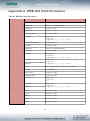
Appendix A. WEB GUI Valid Characters ....................................................................................... 90
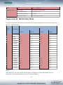
Appendix B. MCS Data Rate ......................................................................................................... 93
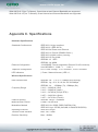
Appendix C. Specifications ........................................................................................................... 94
3
1. Introduction
1.1 Overview
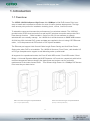
The CERIO 100GX-N eXtreme High Power 11n 150Mbps In Wall PoE Access Point is an
easy-to-install and cost-effective solution for most of indoor wireless deployments, The high
class access point perfect for installation including ;hotel , offices, Luxurious house .
To extend the range and increase the performance of our wireless network. The 100GX-N
provide both a RJ-45 wired connection as well as WiFi wireless connection and provide RJ11
Pass-through function , Build in stable ‘s Cerio Cen-OS 3.0 own software ,a network
administrator can centrally manage the 100GX-N via a Web browser an SNMP MIB browser
& VLAN tag. With included PoE, power and data are supplied to the unit using CAT5 Ethernet
cable. , It use be powered via PoE switch or PoE Injector available.
The Ethernet port support Link-On and Cable Length Power Saving and Link-Down Power
Saving also when PoE is not available. The 100GX-N Structure (Form Factor ) with bundle US
or EU type faceplate set to support In wall Mounting make up and install.
All supports four operational modes, the Pure AP with WDS mode / Pure WDS mode / Client
Bridge + Universal Repeater Mode and WISP Repeater +AP mode etc. respectively with built-in
remote management features simplify the deployment and reduce cost for continued
maintenance of the indoor Access Point .This eXtreme High Power 11n 150Mbps PoE Access
Point must be your best choice.
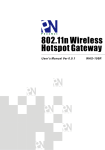
Main Unit with US-Type Faceplate Module
Main Unit with EU-Type Faceplate Module
(U.S.A. / Japan Specification)
(Europe / China Specification)
4
VLAN Tag / SNMP v2c/v3 and Web Based Management interface
Besides supporting IEEE 802.1Q Tag VLAN priority control ,The users to easily handle network
management and maintenance tasks for tthis units . The browser interface permits users to monitor
node condition, link quality, traffic flow, and event log of the 100GX-N units.
The web based management interface also allows Network administrators to easily configure ,
update , and monitor every 100GX-N station . SNMP private MIBs are available for advanced users
preferring to manage through their own network manager.
1.2 Package Contents
IW-100GX-N Packages
100GX-N Main Unit
RJ-45 UTP Cable
x1
x1
In Wall Faceplate Set - 1 (U.S.A Specification)
In Wall Faceplate Set - 2 (Europe Specification)
Wall Mounting Bracket Set
CD Manual
Quick Installation Guide
Warranty Card
x1
x1
x1
x1
x1
x1
WM-100GX-N Packages
100GX-N Main Unit
RJ-45 UTP Cable
Power Adapter (Power Supply)
PoE Adapter
Stand/Mounting Bracket
CD Manual
Quick Installation Guide
Warranty Card
x1
x1
x1
x1
x1
x1
x1
x1
5
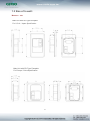
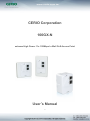
1.3 Size of In wall :
Measure : mm
Main Unit with US-Type Faceplate
For U.S.A. / Japan Specification
Main Unit with EU-Type Faceplate
For Europe / China Specification
6
1.4 Features
Operation Modes : Pure AP+WDS Mode, Pure WDS Mode, Client Bridge Universal
Repeater Mode, WISP Repeater + AP Mode
IEEE 802.11n 1Tx / 1Rx Design, Bandwidth of up to 150Mbps(Tx), 150Mbps(Rx) link rate
800mW at 2.4Ghz Output High Power
Support 8 Multiple-BSSID. And Support IEEE802.11f IAPP
Maximum Security with 802.1X, WAP, and WPA2
Integrated IEEE 802.3af Power over Ethernet (PoE).
Max WDS Link x 8 (Wireless Distribution Service) for Pure WDS Bridge
Build in Wireless RF Signal Enable and Disable by time scheduling function
Enable and Disable to Control and scintillation the dazzling LED light
Support IEEE802.1d Spanning Tree
Integrated IGMP v1/v2/v3 snooping functions and Support Web management
IEEE 802.1Q Tag VLAN priority control and SNMP v1/v2c/v3 , SNMP Traps Supported
Ping Watchdog function support
Auto Channel Scan and support Scan other AP site survey Single information
With bundle Stand Bracket support for Desktop & Wall and Ceiling Mountable Form Factor
Built-in controlled base’s Cerio CenOS3.0 software interface allows for communicating
with CERIO AM-Series AP Management WLAN Switch or Access Controller of network
management servers
Provide Traffic Monitor and Graphical GUI Status Interface.
7
Wireless Feature
Support IEEE802.11n,HT Tx/Rx Stream selection : 1 for 150Mbps(Tx),and 150Mbps(Rx)
Transmission power control : Layer 1~9
Channel selection : Manual or Auto
IEEE802.11f IAPP : to facilitate faster roaming for the stations among different APs nearby
No of associated clients per AP : 32
Support 8 virtual BSSID and associated clients per AP to 32 and the Pure WDS Max. 8
IEEE 802.11d -Multi country roaming
IEEE802.1Q VLAN tag support
IEEE 802.11e WMM QoS ,Diffserv / TOS,IEEE802.1p/COS
Authentication/Encryption (Wireless Security)
WEP 64/128/152 bit /EAP-TLS + Dynamic WEP , EAP-TTLS + Dynamic WEP,
PEAP/MSPEAP + Dynamic WEP
PA-PSK/TKIP,WPA-802.1x/TKIP, 802.11i WPA2-PSK/CCMP/AES 128/256bit, WPA2
(802.1x /CCMP / AES 128/256bit ), No. of registered RADIUS servers : 1
Setting for TKIP/CCMP/AES 128/256bit (ASCII 63 & HEX 64 )key’s refreshing period
WPA2-PSK/CCMP/AES, WPA2(802.1x /CCMP / AES)
Hidden SSID broadcast support
Access Control list (ACL) by MAC and IP Address
Quality of Service
IEEE802.11e WMM
IGMP Snooping V3 Support
DiffServ/TOS , IEEE 802.11p/COS, IEEE 802.1Q Tag VLAN priority control
Management
On line client status monitoring
Real time traffic monitor and status reporting supported
Web-Based management interface, Intuitive Web Management Interface
Support Firmware Upgrade via Web , Reset to Factory Defaults
Support SNMP v1/v2c/v3 , MIB II
SNMP Traps to a List of IP Address
Support Event log and Administrative Access : HTTP and HTTPS/SSL,SSH and support
CLI access via Telnet Management
8
2. Quick Installation
2.1 Basic Settings
100GX-N supports web-based configuration. Upon the completion of hardware installation,
100GX-N can be configured through a PC/NB by using its web browser such as Internet
Explorer 6.0 or later.
Default IP Address: 192.168.2.254
Default Subnet Mask: 255.255.255.0
Default Username and Password: root / default
IP Segment Set-up for Administrator's PC/NB
Set the IP segment of the administrator's computer to be in the same range as 100GX-N for
accessing the system. Do not duplicate the IP Address used here with IP Address of 100GX-N
or any other device within the network.
Example of Segment: (Windows XP)
Step1 :
Click Start -> Settings -> Control Panel, and then “Control Panel” window appears.
Step2 :
Click on “Network Connections”, and then “Network Connections” window appears.
Step3 :
Click right on “Local Area Connection”, and select Properties.
9
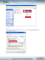
Step4 :
In “Local Area Connection Properties” window, select “Internet Protocol (TCP/IP)” and
click on Properties button.
10
Step5 :
Select “Use the following IP address”, and fix in IP Address : 192.168.2.X
ex. The X is any number by 1 to 253
Subnet mask : 255.255.255.0
And Click "OK" to complete the fixed computer IP setting
========END========
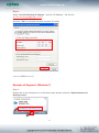
Example of Segment: (Windows 7)
Step 1 :
Please click on the computer icon in the bottom right window, and click “Open Network and
Sharing Center”
11
Step 2 :
In the Network and Sharing Center page, Please click on the left side of “Change adapter
setting” button
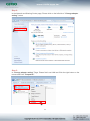
Step 3 :
In “Change adapter setting” Page. Please find Local LAN and Click the right button on the
mouse and Click “Properties”
12
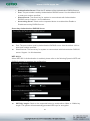
Step 4 :
In “Properties” page, please Click “Properties” button to TCP/IP setting
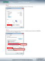
Step 5 :
In Properties page to setting IP address, please find “Internet Protocol Version 4 (TCP/IPv4)”
and double click or click “Install” button.
Double click
Or click Install button
13
Step 6 :
Select “Use the following IP address”, and fix in IP Address : 192.168.2.X
ex. The X is any number by 1 to 253
Subnet mask : 255.255.255.0
And Click "OK" to complete the fixed computer IP setting
Open Web Browser
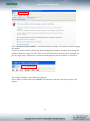
Without a valid certificate, users may encounter the following problem in IE7 when they try to
access system's WMI (https://192.168.2.254). There will be a “Certificate Error”, because the
browser treats system as an illegal website.
14
Click “Continue to this website” to access the system's WMI. The system's Overview page
will appear.
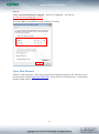
Launch as web browser to access the web management interface of system by entering the
default IP Address, http://192.168.2.254, in the URL field, and then press Enter. Browser will
pop up "login" page. Please key in username and password into the system on 100GX-N.
The system manager Login Page then appears.
Enter “root” as User name and “default” as Password, and then click OK to login to the
system.
15
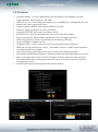
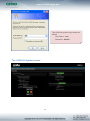
The 100GX-N system login default As
follows
User Name : root
Password : default
The 100GX-N System screen
16
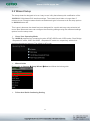
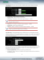
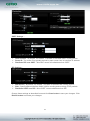
2.2 Wizard Setup
The setup wizard is designed to be an 'easy to use' utility that allows quick modification of the
100GX-N UI Web-based GUI interface settings. The wizard should take no longer than 5
minutes to use. Please be aware that the wizard doesn't give full access to all the setup options
in 100GX-N Indoor AP.
This is purely because the wizard has been designed for a quick and easy setup aimed at all
users. More advanced users can configure the remaining settings using the advanced settings
options from the setup menu.
Chose Your Operating Mode
The 100GX-N supports four operational modes, AP/AP+WDS mode, WDS mode, Client Bridge
+ Repeater AP mode, WISP and WISP + Repeater AP mode etc. respectively with built-in
remote management features. The default is AP mode.
Wizard Guide
Please click on System Setup Wizard Next and follow the below guide.
Follow And Guide Continuing Setting
17
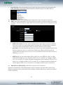
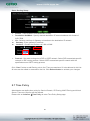
LAN setup Here are the instructions for setup your 100GX-N local LAN IP address and
netmask. If you don’t want change the default 100GX-N IP 192.168.2.254 address, please
keep the default and go next setup.
DNS If you don’t know for your ISP correct DNS IP address, Please click “No default
DNS server” to follow your ISP DNS related IP address.
Wireless Setup If you are not sure which setting to choose, Please then the default
setting to best WiFi smart channel judgment for auto channel, and adjust the output power
to level9 (100%) Extended service set ID indicated the SSID which the clients used to
connect to the access point ESSID.
18
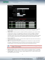
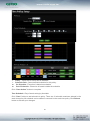
Wireless Security setup Suggested setting that you use wireless encryption
authentication type for security Type : to “WPA2-PSK” the cipher suite : to “AES”, Key
Type : to “ASCII” for 11n high speed mode.
Pre-shared Key : Enter the information for pre-shared key; Pre-shared key can be either
entered as a 256-bit secret in 64 HEX digits format or 8 to 63 ASCII characters. The
Pre-Shared key sample as “xxxxxxxx” wireless encryption key for wireless access.
19
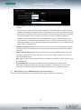
Finishing Wizard
Click Finish button to save your setting. please wait till completion of the reboot process.
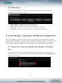
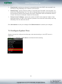
3. AP Mode Configuration
When AP mode is chosen, the system can be configured as an Access Point. This section provides
detailed explanation for users to configure in the AP mode with help of illustrations. In the AP mode,
functions listed in the table below are also available from the Web-based GUI interface.
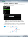
3.1 Chose Your Operating Mode ( AP Mode )
100GX-N Operating mode support four operational modes, AP mode, the WDS mode, the CPE
mode and the Client Bridge + Repeater AP mode, respectively with built-in remote
management features.
The system administrator can set the desired mode via this page, and then configure the
system according to their deployment needs, Please click on System -> Operating Mode and
follow the below setting.
20
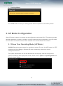
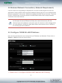
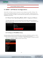
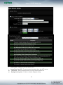
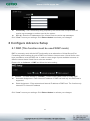
3.2 External Network Connection
Network Requirement
Normally, 100GX-N connects to a wired LAN and provides a wireless connection point to
associate with wireless client. Then, Wireless clients could access to LAN or Internet by
associating themselves with 100GX-N set in AP mode.
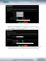
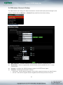
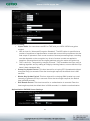
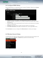
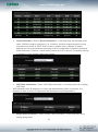
3.3 Configure 100GX-N LAN IP Address
Here are the instructions to setup the local IP Address and Netmask
Please click on System -> LAN and follow the below setting.
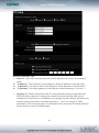
Ethernet Connection Type
Check either “Static IP” or “Dynamic IP” button as desired to set up the system IP of LAN
port.
Static IP: The administrator can manually setup the LAN IP address when static IP is
available/ preferred.
IP Address : The IP address of the LAN port; default IP address is 192.168.2.254
IP Netmask : The Subnet mask of the LAN port; default Netmask is 255.255.255.0
IP Gateway : The default gateway of the LAN port
Dynamic IP: This configuration type is applicable when the 100GX-N is connected to a
network with the presence of a DHCP server; all related IP information will be provided by
the DHCP server automatically.
21
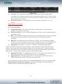
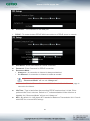
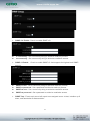
Hostname : The Hostname of the LAN port.
DNS: Check either “No Default DNS Server” or “Specify DNS Server IP” button as
desired to set up the system DNS.
Primary : The IP address of the primary DNS server.
Secondary : The IP address of the secondary DNS server.
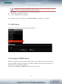
802.1d Spanning Tree
The spanning tree network protocol provides a loop free topology for a bridged LAN between
LAN interface and 8 WDS interfaces from wds0 to wds7. The Spanning Tree Protocol, which is
also referred to as STP, is defined in the IEEE Standard 802.1d
22
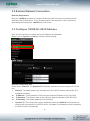
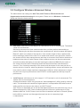
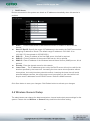
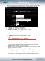
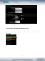
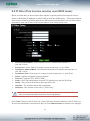
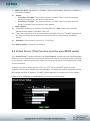
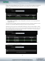
3.4 Wireless General Setup
The administrator can change the data transmission, channel and output power settings for the
system. Please click on Wireless -> General Setup and follow the below setting.
General Setup
MAC Address : The MAC address of the Wireless interface is displayed here.
Band Mode : Select an appropriate wireless band; bands available are 801.11 b/g/n
mixed mode
Country : a region, the 100GX-N support region for US,ETSI and Japan
Channel : Choosing the best WiFi channel
Auto Scan : Smart channel judgment, the function can auto choose use best Channe
AP List : the function support search neighborhood AP and print site survey list
23
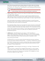
TX Power : You can adjust the output power of the system to get the appropriate
coverage for your wireless network. Specify digit numbers between level 1 to level 9 (the
unit is %) for your environment. If you are not sure which setting to choose, then keep the
default setting level 9 (100%).
RF(on/off) schedule : The 100GX-N can use the schedule control WiFi on or off
function.
Please refer 8.7 Time Policy
HT Physical Mode
Channel Bandwidth : The "20/40” MHz option is usually best. The other option is
available for special circumstances.
Extension Channel : Only for Channel Bandwidth “40” MHz. Select the desired channel
bonding for control.
MCS : This parameter represents transmission rate. By default (Auto) the fastest possible
transmission rate will be selected. You have the option of selecting the speed if
necessary.
Shout GI : Short Guard Interval, by default, it's “Enable”. it's can increase throughput.
However, it can also increase error rate in some installations, due to increased sensitivity
to radio-frequency reflections. Select the option that works best for your installation.
Aggregation : By default, it's “Enable”. To “Disable” to deactivated Aggregation.
A part of the 802.11n standard (or draft-standard). It allows sending multiple frames per single
access to the medium by combining frames together into one larger frame. It creates the larger
frame by combining smaller frames with the same physical source and destination end points and
traffic class (i.e. QoS) into one large frame with a common MAC header.
Aggregation Frames : The Aggregation Frames is in the range of 2~64, default is 32. It
determines the number of frames combined on the new larger frame.
Aggregation Size : The Aggregation Size is in the range of 1024~65535, default is
50000. It determines the size (in Bytes) of the larger frame.
Change these settings as described here and click Save button to save your changes. Click
Reboot button to activate your changes. The items in this page is for AP's RF general
settings and will be applied to all VAPs and WDS Link.
24
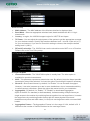
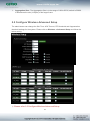
3.5 Configure Wireless Advanced Setup
The administrator can change the Slot Time, ACK Timeout, RTS threshold and
fragmentation threshold settings for the system. Please click on Wireless -> Advanced
Setup and follow the below setting.
Slot Time : Slot time is in the range of 9~1489 and set in unit of microsecond. The default
value is 9 microsecond.
Slot time is the amount of time a device waits after a collision before retransmitting a
packet. Reducing the slot time decreases the overall back-off, which increases throughput.
Back-off, which is a multiple of the slot time, is the random length of time a station waits
before sending a packet on the LAN. For a sender and receiver own right of the channel
the shorter slot time help manage shorter wait time to re-transmit from collision because of
hidden wireless clients or other causes. When collision sources can be removed sooner
and other senders attempting to send are listening the channel(CSMA/CA) the owner of
the channel should continue ownership and finish their transmission and release the
channel. Then, following ownership of the channel will be sooner for the new pair due to
shorter slot time. However, when long duration of existing collision sources and shorter slot
time exist the owners might experience subsequent collisions. When adjustment to longer
slot time can’t improve performance then RTS/CTS could supplement and help improve
performance.
ACK Timeout : ACK timeout is in the range of 1~372 and set in unit of microsecond. The
default value is 64 microsecond.
All data transmission in 802.11b/g request an “Acknowledgement” (ACK) send by receiving
radio. The transmitter will resend the original packet if correspondent ACK failed to arrive
within specific time interval, also refer to as “ACK Timeout”.
ACK Timeout is adjustable due to the fact that distance between two radio links may vary in
different deployment. ACK Timeout makes significant influence in performance of long
distance radio link. If ACK Timeout is set too short, transmitter will start to “Resend” packet
before ACK is received, and throughput become low due to excessively high
re-transmission.
25
ACK Timeout is best determined by distance between the radios, data rate of average
environment. The Timeout value is calculated based on round-trip time of packet with a
little tolerance, So, if experiencing re-transmissions or poor performance the ACK Timeout
could be made longer to accommodate.
Slot Time and ACK Timeout settings are for long distance links. It is important
to tweak settings to achieve the optimal result based on requirement.
Beacon Interval : Beacon Interval is in the range of 40~3500 and set in unit of millisecond.
The default value is 100 msec.
Access Point (AP) in IEEE 802.11 will send out a special approximated 50-byte frame,
called “Beacon”. Beacon is broadcast to all the stations, provides the basic information of
AP such as SSID, channel, encryption keys, signal strength, time stamp, support data rate.
All the radio stations received beacon recognizes the existence of such AP, and may
proceed next actions if the information from AP matches the requirement. Beacon is sent
on a periodic basis, the time interval can be adjusted.
By increasing the beacon interval, you can reduce the number of beacons and associated
overhead, but that will likely delay the association and roaming process because stations
scanning for available access points may miss the beacons. You can decrease the beacon
interval, which increases the rate of beacons. This will make the association and roaming
process very responsive; however, the network will incur additional overhead and
throughput will go down.
DTIM Interval : The DTIM interval is in the range of 1~255. The default is 1.
DTIM is defined as Delivery Traffic Indication Message. It is used to notify the wireless
stations, which support power saving mode, when to wake up to receive multicast frame.
DTIM is necessary and critical in wireless environment as a mechanism to fulfill
power-saving synchronization.
A DTIM interval is a count of the number of beacon frames that must occur before the
access point sends the buffered multicast frames. For instance, if DTIM Interval is set to 3,
then the Wi-Fi clients will expect to receive a multicast frame after receiving three Beacon
frame. The higher DTIM interval will help power saving and possibly decrease wireless
throughput in multicast applications.
RTS Threshold : TRTS Threshold is in the range of 1~2347 byte. The default is 2347
byte.
The main purpose of enabling RTS by changing RTS threshold is to reduce possible
collisions due to hidden wireless clients. RTS in AP will be enabled automatically if the
packet size is larger than the Threshold value. By default, RTS is disabled in a normal
environment supports non-jumbo frames.
26
Short Preamble : By default, it’s “Enable”. To Disable is to use Long 128-bit Preamble
Synchronization field.
The preamble is used to signal "here is a train of data coming" to the receiver. The short
preamble provides 72-bit Synchronization field to improve WLAN transmission efficiency
with less overhead.
IGMP Snooping : the process of listening to Internet Group Management Protocol (IGMP)
network traffic. The feature allows a network switch to listen in on the IGMP conversation
between hosts and routers. By listening to these conversations the switch maintains a
map of which links need which IP multicast streams. Multicasts may be filtered from the
links which do not need them and thus controls which ports receive specific multicast
traffic.
Greenfield : In wireless WLAN technology, greenfield mode is a feature of major
components of the 802.11n specification. The greenfield mode feature is designed to
improve efficiency by eliminating support for 802.11b/g devices in an all draft-n network. In
greenfield mode the network can be set to ignore all earlier standards.
WMM QoS : This affects traffic flowing from the access point to the client station.
Configuring QoS options consists of setting parameters on existing queues for different
types of wireless traffic. You can configure different minimum and maximum wait times for
the transmission of packets in each queue based on the requirements of the media being
sent. Queues automatically provide minimum transmission delay for Voice, Video,
multimedia, and mission critical applications, and rely on best-effort parameters for
traditional IP data.
As an Example, time-sensitive Voice & Video, and multimedia are given effectively higher
priority for transmission (lower wait times for channel access), while other applications and
traditional IP data which are less time-sensitive but often more data-intensive are expected
to tolerate longer wait times.
27
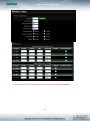
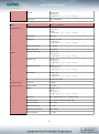
AC Type:
Queue
Data Transmitted
AP to Clients
Priority
Description
AC_BK
Background
Low
AC_BE
Best Effort
Medium
AC_VI
Video
High
AC_VO
Voice
High
High throughput. Bulk data that requires maximum
throughput and is not time-sensitive is sent to this
queue (FTP data, for example).
Medium throughput and delay. Most traditional IP
data is sent to this queue.
Minimum delay. Time-sensitive video data is
automatically sent to this queue.
Time-sensitive data like VoIP and streaming media
are automatically sent to this queue.
CWmin:Minimum Contention Window. This parameter is input to the algorithm that
determines the initial random backoff wait time ("window") for retry of a transmission.
The value specified here in the Minimum Contention Window is the upper limit (in
milliseconds) of a range from which the initial random backoff wait time is
determined.。
CWmax:Maximum Contention Window. The value specified here in the Maximum
Contention Window is the upper limit (in milliseconds) for the doubling of the random
backoff value. This doubling continues until either the data frame is sent or the
Maximum Contention Window size is reached. Once the Maximum Contention
Window size is reached, retries will continue until a maximum number of retries
allowed is reached. Valid values for the "cwmax" are 1, 3, 7, 15, 31, 63, 127, 255, 511,
or 1024. The value for "cwmax" must be higher than the value for "cwmin".。
28
AIFS:The Arbitration Inter-Frame Spacing Number specifies a wait time (in
milliseconds) for data frames。
TxOP Limit:Transmission Opportunity is an interval of time when a WME AP has the
right to initiate transmissions onto the wireless medium (WM). This value specifies (in
milliseconds) the Transmission Opportunity (TXOP) for AP; that is, the interval of time
when the WMM AP has the right to initiate transmissions on the wireless network.。
ACM bit:Admission Control Mandatory, ACM only takes effect on AC_VI and AC_VO.
When you do not click Checkbox, it means that the ACM is controlled by the
connecting AP. If you click Checkbox, it means that the Client is in charge。
No ACK policy bit:Acknowledgment Policy, WMM defines two ACK policies: Normal
ACK and No ACK. Click “Checkbox” indicates “No ACK”
When the no acknowledgement (No ACK) policy is used, the recipient does not
acknowledge received packets during wireless packet exchange. This policy is suitable in
the environment where communication quality is fine and interference is weak. While the
No ACK policy helps improve transmission efficiency, it can cause increased packet loss
when communication quality deteriorates. This is because when this policy is used, a
sender does not retransmit packets that have not been received by the recipient.
When the Normal ACK policy is used, the recipient acknowledges each received uncast
packet.。
Change these settings as described here and click Save button to save your changes.
Click Reboot button to activate your changes.
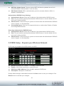
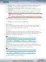
3.6 Create Virtual AP – Virtual AP Setup
The administrator can create Virtual AP via this page. Please click on Wireless -> Virtual AP
Setup and follow the below setting.
VAP: Display number of system's Virtual AP.
MAC Address : The MAC address of the VAP Interface is displayed here. When you
enable AP and reboot system, the MAC address will display here
29
ESSID: Display Virtual AP's ESSID; default is AP00~AP07.
Status: Display VAP status; default VAP0 is always on and only VAP0 can support WPS
function.
Security Type: Display Virtual AP's Security Type; default is disabled.
MAC Filter Setup: Click “Setup” button for configuring Virtual AP's Access Control List.
VAP Edit: Click “Edit” button for configuring Virtual AP's settings and security type.
Change these settings as described here and click Save button to save your changes. Click
Reboot button to activate your changes
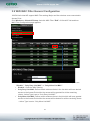
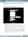
3.7 Virtual AP General Configuration
For each Virtual AP, administrators can configure general settings and security type. Click
Wireless -> Virtual AP Setup, click “Edit” of Virtual AP List and then Virtual AP Configuration
page appears.
30
ESSID: Extended Service Set ID indicates the SSID which the clients used to connect to
the VAP. ESSID will determine the service type of a client which is assigned to the
specified VAP.
Hidden SSID: Select this option to enable the SSID to broadcast in your network. When
configuring the network, it is suggested to enable this function but disable it when the
configuration is complete. With this enabled, someone could easily obtain the SSID
information with the site survey software and get unauthorized access to a private network.
With this disabled, network security is enhanced and can prevent the SSID from begin
seen on networked.
Client Isolation: Select Enable, all clients will be isolated from each other, that means all
clients can not reach to other clients.
IAPP: Inter Access-Point Protocol is designed for the enforcement of unique association
throughout a ESS(Extended Service Set) and for secure exchange of station's security
context between current access point (AP) and new AP during hand off period.
Notice: IAPP only used on WPA-PSK and WPA2-PSK security type. Only one
of VAPs can be enabled.
Maximum Clients: Enter maximum number of clients to a desired number. For example,
while the number of client is set to 32, only 32 clients are allowed to connect with this VAP.
VLAN Tag(ID): Virtual LAN, the system supports tagged VLAN. To enable VLAN function;
valid values are from 0 to 4094.
31
Security Type: Select the desired security type from the drop-down list; the options are
WEP, WPA-PSK, WPA2-PSK, WPA-Enterprise, WPA2-Enterprise and WEP 802.1X.
Disable: Data are unencrypted during transmission when this option is selected.
WEP: WEP, Wired Equivalent Privacy, is a data encryption mechanism based on a 64-bit,
128-bit or 152-bit shared key. Select WEP as the security type from the drop down list as
desired.
Key Length: The key size of WEP encryption can be 64bit, 128bit or 152bit.
WEP auth method: You can select the appropriate value: Open system (If enabling
this mode, there is no need authentication to access AP or Wireless NIC) or Shared
(Only those who are sharing the same key with the AP can connect with it).
Key Index: You can select the Key which you want to use. Other wireless station must
have the same key value to connect with 100GX-N, 4 different WEP keys can be
configured at the same time, but only one is used. Effective key is set with a choice of
WEP Key 1, 2, 3 or 4.
WEP Key #: You can chose either HEX or ASCII for your WEP key value, for 64bit
encryption strength can use 10 digits for HEX (0~9, a~f and A-F) or 5 digits for ASCII
(0~9, a~z and A~Z), for 128bit encryption strength can use 26 digits for HEX (0~9, a~f
and A-F) or 13 digits for ASCII (0~9, a~z and A~Z), for 152bit encryption strength can
use 32 digits for HEX (0~9, a~f and A-F) or 16 digits for ASCII (0~9, a~z and A~Z)
WPA-PSK (or WPA2-PSK): WPA-PSK is short for W-Fi Protected
Access-Pre-Shared Key. WPA-SPK uses the same encryption way with WPA, and the only
difference between them is that WPA-PSK recreates a simple shared key, instead of using the
user’s certification.
32
Cipher Suite: You can chose use AES or TKIP with your WPA / WPA2 encryption
method
AES is short for “Advanced Encryption Standard”, The AES cipher is specified as a
number of repetitions of transformation rounds that convert the input plaintext into the
final output of ciphertext. Each round consists of several processing steps, including
one that depends on the encryption key. A set of reverse rounds are applied to
transform ciphertext back into the original plaintext using the same encryption key.
TKIP is short for “Temporal Key Integrity Protocol”, TKIP scrambles the keys using a
hashing algorithm and, by adding an integrity-checking feature, ensures that the keys
haven’t been tampered with.
Group Key Update Period: This time interval for re-keying GTK (broadcast/multicast
encryption keys) in seconds. Enter the time-length required; the default time is 600
seconds.
Master Key Update Period: This time interval for re-keying GMK (master key used
internally to generate GTKs) in seconds. Enter the time-length required; the default
time is 83400 seconds.
Key Type: Check on the respected button to enable either ASCII or HEX format for the
Pre-shared Key.
Pre-Shared Key: Enter the information for pre-shared key; the format of the
information shall according to the key type selected. Pre-shared key can be either
entered as a 256-bit secret in 64 HEX digits format, or 8 to 63 ASCII characters.
WPA-Enterprise (or WPA2-Enterprise) General Setting
The RADIUS authentication and encryption will be both enabled if this selected.
33
General Setting :
Cipher Suite: You can chose use AES or TKIP with your WPA / WPA2 encryption
method
AES is short for “Advanced Encryption Standard”, The AES cipher is specified as a
number of repetitions of transformation rounds that convert the input plaintext into the
final output of ciphertext. Each round consists of several processing steps, including
one that depends on the encryption key. A set of reverse rounds are applied to
transform ciphertext back into the original plaintext using the same encryption key.
TKIP is short for “Temporal Key Integrity Protocol”, TKIP scrambles the keys using a
hashing algorithm and, by adding an integrity-checking feature, ensures that the keys
haven’t been tampered with.
Group Key Update Period: This time interval for re-keying GTK (broadcast/multicast
encryption keys) in seconds. Enter the time-length required; the default time is 600
seconds.
Master Key Update Period: This time interval for re-keying GMK (master key used
internally to generate GTKs) in seconds. Enter the time-length required; the default
time is 83400 seconds.
EAP Reauth Period: This time interval for re- authentication in seconds. Enter the
time-length required; the default time is 3600 seconds; 0 = disable re-authentication.
Authentication RADIUS Server Settings
34
Authentication Server: Enter the IP address of the Authentication RADIUS server.
Port: The port number used by Authentication RADIUS server. Use the default 1812
or enter port number specified.
Shared secret: The secret key for system to communicate with Authentication
RADIUS server. Support 1 to 64 characters.
Accounting Server: Check on the respected button to enable either Enable or
Disable accounting RADIUS server.
Secondary Authentication RADIUS Server
Server IP: Enter the IP address of the Authentication RADIUS server.
Port: The port number used by Authentication RADIUS server. Use the default 1812 or
enter port number specified.
Shared secret: The secret key for system to communicate with Authentication RADIUS
server. Support 1 to 64 characters.
WEP 802.1x
When WEP 802.1x Authentication is enabled, please refer to the following Dynamic WEP and
RADIUS settings to complete the configuration.
Dynamic WEP Settings
WEP Key length: Check on the respected button to enable either 64bits or 128bits key
length. The system will automatically generate WEP keys for encryption.
35
WEP Key Update Period: The time interval WEP will then be updated; the unit is in
seconds; default is 300 seconds; 0 = do not rekey.
EAP Reauth Period: EAP re-authentication period in seconds; default is 3600; 0 =
disable re-authentication.
Authentication RADIUS Server Settings
Authentication Server: Enter the IP address of the Authentication RADIUS server.
Port: The port number used by Authentication RADIUS server. Use the default 1812 or
enter port number specified.
Shared secret: The secret key for system to communicate with Authentication RADIUS
server. Support 1 to 64 characters.
Accounting Server: Check on the respected button to enable either Enable or Disable
accounting RADIUS server.
Secondary Authentication RADIUS Server
Authentication Server: Enter the IP address of the Authentication RADIUS server.
Port: The port number used by Authentication RADIUS server. Use the default 1812 or
enter port number specified.
Shared secret: The secret key for system to communicate with Authentication RADIUS
server. Support 1 to 64 characters.
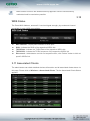
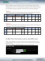
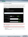
3.8 WDS Setup - Expand your Wireless Network
In AP mode only supports four WDS function on VAP0
Service: By default, it's “Disable”. To “Enable” to activate WDS
Enable: Click Enable checkbox to create WDS link.
WDS Peer's MAC Address: Enter the MAC address of WDS peer.
Description: Description of WDS link.
Change these settings as described here and click Save button to save your changes. Click
Reboot button to activate your changes.
36
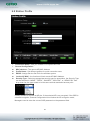
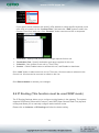
3.9 WiFi MAC Filter General Configuration
100GX-N all virtual AP support MAC Filter setting, Major can filter wireless users connected to
Access Point.
Click Wireless -> Virtual AP Setup, And click MAC Filter “Edit” of Virtual AP List and then
MAC Filter Configuration page appears.
Action: Select the desired access control type from the drop-down list; the options are
“Disable”, “Only Deny List MAC” or “Only Allow List MAC”.
Disable : Close the MAC filtering.
Only Deny List MAC: Define certain wireless clients in the list which will have denied
access to the Access Point while the access will be granted for all the remaining
clients - Action Type is set to “Only Deny List MAC”.
Only Allow List MAC: Define certain wireless clients in the list which will have granted
access to the Access Point while the access will be denied for all the remaining clients
– Action Type is set to “Only Allow List MAC”.
37
MAC Access Control is the weakest security approach. WPA or WPA2 security
methods should be used when possible.
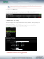
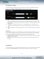
3.10
WDS Status
The Peers MAC Address, antenna 0/1 received signal strength, phy mode and channel
bandwidth for each WDS are available.
MAC Address : Display MAC address of WDS peer.
RSSI : Indicate the RSSI of the respective WDS's link.
TX/RX Rate : Indicate the TX/RX Rate of the respective WDS's link
TX/RX SEQ : Indicate the TX/RX sequence of the respective WDS's link
Disconnect : Administrator can kick out a specific client, click “Delete” button to kick out
specific WDS's link.
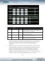
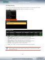
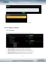
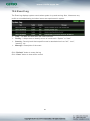
3.11 Associated Clients
The administrator can obtain detailed wireless information and all associated clients status via
this page. Please click on Wireless -> Associated Clients. The the Associated Clients Status
appears.
38
Wireless Information : Display the Virtual AP configuration information of the system.
VAP : Display number of system's Virtual AP.
ESSID : Extended Service Set ID of the Virtual AP.
Status : Display Virtual AP status currently.
Security Type : Security type activated by the Virtual AP.
Clients : Number of clients currently associated to the Virtual AP.
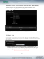
VAP0 Associated Client Status
MAC Address : Users already connected to the AP, will display the user's MAC number
RSSI : Show signal quality by users to connect the AP
TX/RX Rate : Show using upload/download the wireless bandwidth Rate
TX/RX SEQ : Show the TX/RX sequence.
TX/RX Bytes : Show Current usage
Connect Time : Show users connect Time.
Actions : The button is excluded at present connected users.
4. WDS Mode Configuration
When WDS mode is chosen, the system can be configured as an WDS mode. This section provides
detailed explanation for users to configure in the WDS mode with help of illustrations. In the WDS
mode, functions listed in the table below are also available from the Web-based GUI interface.
4.1 Chose Your Operating Mode ( WDS Mode )
The system administrator can set the desired mode via this page, and then configure the
system according to their deployment needs, Please click on System -> Operating Mode and
follow the below setting.
39
4.2 Configure 100GX-N LAN IP Address
Here are the instructions to setup the local IP Address and Netmask
Please click on System -> LAN and follow the below setting.
※ Please refer 3.3 Configure 100GX-N LAN IP Address LAN IP Setting.
40
4.3 Wireless General Settings
The administrator can change the data transmission, channel and output power settings for the
system. Please click on Wireless -> General Setup and follow the below setting.
※ Please refer 3.4 Wireless General Setup
4.4 Configure Wireless Advanced Setup
The administrator can change the Slot Time, ACK Timeout, RTS threshold and fragmentation
threshold settings for the system. Please click on Wireless -> Advanced Setup and follow the
below setting.
41
※ Please refer 3.5 Configure Wireless Advanced Setup
4.5 WDS Setup
The administrator could create WDS Links to expand wireless network. When WDS is enabled,
access point functions as a wireless bridge and is able to communicate with other access
points via WDS links. A WDS link is bidirectional and both side must support WDS. Access
points know each other by MAC Address. In other words, each access point needs to include
MAC address of its peer. Ensure all access points are configured with the same channel and
own same security type settings.
42
Security Type : Option is “Disable”, “WEP”, “TKIP”or “AES” from drop-down list. Needs
the same type to build WDS links. Security type takes effect when WDS is enabled.
WEP Key : Enter 5 / 13 ASCII or 10 / 26 HEX format WEP key.
AES Key : Enter 8 to 63 ASCII or 64 HEX format AES key.
WDS MAC List
Enable : Check “Enable” to create WDS link.
WDS Peer's MAC Address : Enter the MAC address of WDS peer.
VLAN Tag(ID): Virtual LAN, the system supports tagged VLAN with WDS. To enable
VLAN function; valid values are from 0 to 4094; space is disabled.
Description : Description of WDS link.
The WDS link needs to be set at same Channel and with same Security
Type.
Click Save button to save your changes. Click Reboot button to activate your changes.
43
4.6 WDS Status
The Peers MAC Address, antenna 0/1 received signal strength, phy mode and channel
bandwidth for each WDS are available.
MAC Address : Display MAC address of WDS peer.
RSSI : Indicate the RSSI of the respective WDS's link.
TX/RX Rate : Indicate the TX/RX Rate of the respective WDS's link
TX/RX SEQ : Indicate the TX/RX sequence of the respective WDS's link
5. Client Bridge + Repeater AP Mode Configuration
When Client Bridge + Repeater AP Mode is chosen, the system can be configured as an Client
Bridge + Repeater APMode. This section provides detailed explanation for users to configure in the
Client Bridge + Repeater AP Mode with help of illustrations. In the Client Bridge + Repeater AP
Mode, functions listed in the table below are also available from the Web-based GUI interface.
5.1 Chose Your Operating Mode(Client Bridge + Repeater
AP)
The system administrator can set the desired mode via this page, and then configure the
system according to their deployment needs, Please click on System -> Operating Mode and
follow the below setting.
44
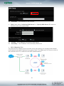
5.2 External Network Connection ( Network Requirement )
It can be used as an Client Bridge or Repeater AP to receive wireless signal over last mile
applications, helping WISPs deliver wireless broadband Internet service to new residential and
business customers. In this mode, 100GX-N is enabled with DHCP Server functions. The wired
clients of 100GX-N are in the same subnet from Main Base Station and it accepts wireless
connections from client devices.
When the 100GX-N configured as an Access Point and Client Station simultaneously,
the Wireless General and Advanced Setup also used simultaneously. But the
Security Type can be different. In the other word, the channel or other settings will be
the same between 100GX-N to Main Base Station and wireless client to 100GX-N,
but security type can be different.
5.3 Configure 100GX-N LAN IP Address
Here are the instructions for how to setup the local IP Address and Netmask. Please click on
System -> LAN and follow the below setting.
※ Please refer 3.3 Configure 100GX-N LAN IP Address LAN IP Setting.
45
DHCP Server
Devices connected to the system can obtain an IP address automatically when this service is
enabled.
DHCP : Check Enable button to activate this function or Disable to deactivate this
service.
Start IP / End IP: Specify the range of IP addresses to be used by the DHCP server when
assigning IP address to clients. The default range IP address is 192.168.2.10 to
192.168.2.70, the netmask is 255.255.255.0
DNS1 IP : Enter IP address of the first DNS server; this field is required.
DNS2 IP : Enter IP address of the second DNS server; this is optional.
WINS IP : Enter IP address of the Windows Internet Name Service (WINS) server; this is
optional.
Domain : Enter the domain name for this network.
Lease Time : The IP addresses given out by the DHCP server will only be valid for the
duration specified by the lease time. Increasing the time ensure client operation without
interruptions, but could introduce potential conflicts. Lowering the lease time will avoid
potential address conflicts, but might cause more interruptions to the client while it will
acquire new IP addresses from the DHCP server. Default is 86400 seconds
Click Save button to save your changes. Click Reboot button to activate your changes
5.4 Wireless General Setup
The administrator can change the data transmission, channel and output power settings for the
system. Please click on Wireless -> General Setup and follow the below setting.
46
General Setup
MAC Address : The MAC address of the Wireless interface is displayed here.
Band Mode : Select an appropriate wireless band; bands available are 801.11 b/g/n
mixed mode
Country : a region, the 100GX-N support region for US,ETSI and Japan
TX Power : You can adjust the output power of the system to get the appropriate coverage
for your wireless network. Specify digit numbers between level 1 to level 9 (the unit is %)
for your environment. If you are not sure which setting to choose, then keep the default
setting level 9 (100%)
RF(on/off) schedule : The 100GX-N can use the schedule control WiFi on or off function.
Please refer to the Time Policy setup.
HT Physical Mode
Channel Bandwidth : The "20/40” MHz option is usually best. The other option is
available for special circumstances.
MCS : This parameter represents transmission rate. By default (Auto) the fastest possible
transmission rate will be selected. You have the option of selecting the speed if necessary.
Shout GI : Short Guard Interval, by default, it's “Enable”. it's can increase throughput.
However, it can also increase error rate in some installations, due to increased sensitivity
to radio-frequency reflections. Select the option that works best for your installation.
Aggregation : By default, it's “Enable”. To “Disable” to deactivated Aggregation.
A part of the 802.11n standard (or draft-standard). It allows sending multiple frames per
single access to the medium by combining frames together into one larger frame. It creates
the larger frame by combining smaller frames with the same physical source and
destination end points and traffic class (i.e. QoS) into one large frame with a common MAC
header.
Aggregation Frames : The Aggregation Frames is in the range of 2~64, default is 32. It
determines the number of frames combined on the new larger frame.
47
Aggregation Size : The Aggregation Size is in the range of 1024~65535, default is 50000.
It determines the size (in Bytes) of the larger frame.
5.5 Configure Wireless Advanced Setup
The administrator can change the Slot Time, ACK Timeout, RTS threshold and fragmentation
threshold settings for the system. Please click on Wireless -> Advanced Setup and follow the
below setting.
※ Please refer 3.5 Configure Wireless Advanced Setup
48
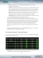
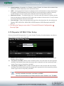
5.6 Site Survey
Use this tool to scan and locate WISP Access Points and select one to associate with. Please
click on Wireless -> Site Survey. Below depicts an example for site survey.
ESSID : Available Extend Service Set ID of surrounding Access Points.
MAC Address : MAC addresses of surrounding Access Points.
Signal/Noise dBm : Received signal strength of all found Access Points.
RSSI : Indicate the RSSI of the respective client's association.
Signal Quality (%) : Received signal strength of all found Access Points.
Channel : Channel numbers used by all found Access Points.
Security : Security type by all found Access Points.
Select : Click “Select” to configure settings and associate with chosen AP.
While clicking “Select” button in the Site Survey Table, the “ESSID” and “Security
Type” will apply in the Wireless General Setup. However, more settings are needed
including Security Key.
49
5.7 Station Profile
Connection Setup : Can you choose Fix or cycle to AP Link.
General Configuration :
MAC address : The remote AP MAC Address
Profile Name : Set different profiles for quick connection uses.
ESSID : Assign Service Set ID for the wireless system.
Lock to AP MAC : the function will lock remote AP MAC Address.
Security Type : Select an appropriate security type for association, the Security Type
can be selected in “NONE”, “OPEN”, “SHARED”, “WPA-PSK”, or “WPA2-PSK” from
drop-down list; the type needs to be the same as that associated access point.
Usually choose to connect an AP site, If the selected AP is an encrypted, If the SSID is
selected encryption, General Configuration list will show the AP encryption mode,
Managers need to enter the correct SSID password on the password field.
50
If you only click “Connect” button and does not click “Save” button. The selected
profile would not be saved on the Profile List
Change these settings as described here and click Save button to save your changes. Click
Reboot button to activate your changes.
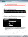
5.8 Remote AP Status
Show the remote bridge AP whether is link or unlinked
5.9 Repeater AP Setup
The network manager can configure related wireless settings, AP Setup, Security Settings, and
Access Control Settings.
Administrators can configure ESSID, SSID broadcasting, Maximum number of client
associations, security type settings and MAC Filter settings.
ESSID : Extended Service Set ID, When clients are browsing for available wireless
networks, this is the SSID that will appear in the list. ESSID will determine the service type
available to AP clients associated with the specified VAP.
Enable Repeater AP : choose Enable or Disable Repeater AP function, the default is
Disable
Hidden SSID : By default, it’s “Disable”. Enable this option to stop the SSID broadcast in
your network. When disabled, people could easily obtain the SSID information with the site
survey software and get access to the network if security is not turned on. When enabled,
network security is enhanced. It’s suggested to enable it after AP security settings are
archived and setting of AP clients could make to associate to it.
51
Client Isolation : By default, it’s “Disable”. Select “Enable”, all clients will be isolated from
each other, which means they can’t reach each other.
IAPP : Inter Access-Point Protocol is designed for the enforcement of unique association
throughout a ESS(Extended Service Set) and for secure exchange of station's security
context between current access point (AP) and new AP during hand off period.
Maximum Clients : The default value is 32. You can enter the number of wireless clients
that can associate to a particular SSID. When the number of client is set to 5, only 5 clients
at most are allowed to connect to this VAP.
Security Type : Select the desired security type from the drop-down list; the options are
Disable, WEP, WPA-PSK, WPA2-PSK, WPA-Enterprise, WPA2-Enterprise and WEP
802.1X.
※ The Security Type you can refer 3.7 Virtual AP General Configuration
Security Type
5.10 Repeater AP MAC Filter Setup
Continue Virtual AP Setup section. For each Virtual AP setting, the administrator can allow or
reject clients to access each Virtual AP.
Action: Select the desired access control type from the drop-down list; the options are
Disable, Allow or Reject.
Only Allow List MAC: Define certain wireless clients in the list which will have granted
access to the Access Point while the access will be denied for all the remaining clients –
Action Type is set to “Only Allow List MAC”.
Only Deny List MAC: Define certain wireless clients in the list which will have denied
access to the Access Point while the access will be granted for all the remaining clients Action Type is set to “Only Deny List MAC”.
MAC Access Control is the weakest security approach. WPA or WPA2
security methods should be used when possible.
There are a maximum of 20 clients allowed in this “Enable” List. The MAC
52
addresses of the wireless clients can be added and removed to the list
using the Add and Remove buttons.
6. WISP + AP Mode Configuration
When WISP + AP Mode is chosen, the system can be configured as an WISP + AP Mode. This
section provides detailed explanation for users to configure in the WISP + AP Mode with help of
illustrations. In the WISP + AP Mode, functions listed in the table below are also available from the
Web-based GUI interface.
6.1 Chose Your Operating Mode ( WISP + Repeater AP Mode )
The system administrator can set the desired mode via this page, and then configure the
system according to their deployment needs, Please click on System -> Operating Mode and
follow the below setting.
6.2 Configure CPE(WAN) Setup
It can be used as an Router AP with WDS function. In this mode, 100GX-N is a gateway enabled
with NAT and DHCP Server functions. The wireless clients connected to Internet.
There are Four connection types for the WAN port : Static IP, Dynamic IP, PPPoE and PPTP.
Please click on System -> CPE and follow the below setting.
53
Internet connection Type
Static IP : Users can manually setup the WAN IP address with a static IP provided by
WISP.
IP Address : The IP address of the WAN port; default IP address is 192.168.1.254
IP Netmask : The Subnet mask of the WAN port; default Netmask is 255.255.255.0
IP Gateway : The default gateway of the WAN port; default Gateway is 192.168.1.1
Dynamic IP : Please consult with WISP for correct wireless settings to associate with
WISP AP before a dynamic IP, along with related IP settings including DNS can be
available from DHCP server. If IP Address is not assigned, please double check with your
wireless settings and ensure successful association. Also, you may go to “WAN
Information” in the Overview page to click Release button to release IP address and click
Renew button to renew IP address again.
54
Hostname : The Hostname of the WAN port
PPPoE : To create wireless PPPoE WAN connection to a PPPoE server in network.
User Name : Enter User Name for PPPoE connection
Password : Enter Password for PPPoE connection
Reconnect Mode :
Always on – A connection to Internet is always maintained.
On Demand – A connection to Internet is made as needed.
When Time Server is enabled at the “On Demand” mode, the
“Reconnect Mode” will turn out “Always on”.
Manual – Click the “Connect” button on “WAN Information” in the Overview page to
connect to the Interne
Idle Time : Time to last before disconnecting PPPoE session when it is idle. Enter
preferred Idle Time in minutes. Default is “0”, indicates disabled. When Idle time is
disabled, the “Reconnect Mode” will turn out “Always on”
MTU : By default, it’s 1492 bytes. MTU stands for Maximum Transmission Unit. Consult
with WISP for a correct MTU setting.t.
55
PPTP : The Point-to-Point Tunneling Protocol (PPTP) mode enables the implementation
of secure multi-protocol Virtual Private Networks (VPNs) through public networks.
IP Address : The IP address of the WAN port
IP Netmask : The Subnet mask of the WAN port
PPTP Server IP Address : The IP address of the PPTP server
User Name : Enter User Name for PPTP connection
Password : Enter Password for PPTP connection
Reconnect Mode :
Always on – A connection to Internet is always maintained.
On Demand – A connection to Internet is made as needed.
When Time Server is enabled at the “On Demand” mode, the
“Reconnect Mode” will turn out “Always on”.
Manual – Click the “Connect” button on “WAN Information” in the Overview page to
connect to the Interne
Idle Time : Time to last before disconnecting PPPoE session when it is idle. Enter
preferred Idle Time in minutes. Default is “0”, indicates disabled. When Idle time is
disabled, the “Reconnect Mode” will turn out “Always on”
MTU : By default, it’s 1492 bytes. MTU stands for Maximum Transmission Unit. Consult
with WISP for a correct MTU setting.t.
MPPE Encryption : Microsoft Point-to-Point Encryption (MPPE) encrypts data in
Point-to-Point Protocol(PPP)-based dial-up connections or Point-to-Point Tunneling
Protocol (PPTP) virtual private network (VPN) connections. 128-bit key (strong) and
40-bit key (standard) MPPE encryption schemes are supported. MPPE provides data
security for the PPTP connection that is between the VPN client and the VPN server.
56
DNS : Check “No Default DNS Server” or “Specify DNS Server IP” radial button as desired
to set up system DNS.
Primary : The IP address of the primary DNS server.
Secondary : The IP address of the secondary DNS server.
NAT : The NAT support Enable and Disable Service
MAC Clone : The MAC address is a 12-digit HEX code uniquely assigned to hardware as
identification. Some ISPs require you to register a MAC address in order to access to
Internet. If not, you could use default MAC or clone MAC from a PC.
Keep Default MAC Address : Keep the default MAC address of WAN port on the system.
Clone MAC Address : If you want to clone the MAC address of the PC, then click the
Clone MAC Address button. The system will automatically detect your PC's MAC
address.
The Clone MAC Address field will display MAC address of the PC
connected to system. Click “Save” button can make clone MAC
effective.
Manual MAC Address : Enter the MAC address registered with your ISP.
Click Save button to save your changes. Click Reboot button to activate your changes
57
6.3 Configure 100GX-N LAN IP Address
Here are the instructions for how to setup the local IP Address and Netmask. Please click on
System -> LAN and follow the below setting.
LAN Setup
IP Address : The IP address of the LAN port; default IP address is 192.168.2.254
IP Netmask : The Subnet mask of the LAN port; default Netmask is 255.255.255.0
802.1d Spanning Tree
The spanning tree network protocol provides a loop free topology for a bridged LAN between
LAN interface and 8 WDS interfaces from wds0 to wds7. The Spanning Tree Protocol, which is
also referred to as STP, is defined in the IEEE Standard 802.1d
58
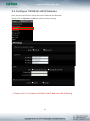
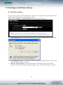
6.4 Configure DDNS Setup
Dynamic DNS allows you to map domain name to dynamic IP address. Please click on System
-> DDNS Setup and follow the below setting.
Enabled: By default, it’s “Disable”. The mapping domain name won’t change when
dynamic IP changes. The beauty of it is no need to remember the dynamic WAP IP while
accessing to it.
Service Provider: Select the preferred Service Provider from the drop-down list including
dyndns, dhs, ods and tzo
Hostname: Host Name that you register to Dynamic-DNS service and export.
User Name & Password: User Name and Password are used to login DDNS service.
Click Save button to save your changes Click Reboot button to activate your changes
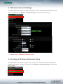
6.5 Wireless General Setup
The administrator can change the data transmission, channel and output power settings for the
system. Please click on Wireless -> General Setup and follow the below setting.
59
※ Please refer 3.4 Wireless General Setup Explanation
6.6 Configure Wireless Advanced Setup
The administrator can change the Slot Time, ACK Timeout, RTS threshold and fragmentation
threshold settings for the system. Please click on Wireless -> Advanced Setup and follow the
below setting.
60
※ Please refer 3.5 Configure Wireless Advanced Setup Explanation
61
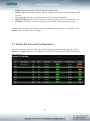
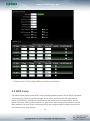
6.7 Site Survey
Use this tool to scan and locate WISP Access Points and select one to associate with. Please
click on Wireless -> Site Survey. Below depicts an example for site survey.
ESSID : Available Extend Service Set ID of surrounding Access Points.
MAC Address : MAC addresses of surrounding Access Points.
Signal/Noise dBm : Received signal strength of all found Access Points.
RSSI : Indicate the RSSI of the respective client's association.
Signal Quality (%) : Received signal strength of all found Access Points.
Channel : Channel numbers used by all found Access Points.
Security : Security type by all found Access Points.
Select : Click “Select” to configure settings and associate with chosen AP.
While clicking “Select” button in the Site Survey Table, the “ESSID” and “Security
Type” will apply in the Wireless General Setup. However, more settings are needed
including Security Key.
62
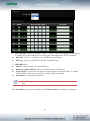
6.8 Station Profile
Connection Setup : Can you choose Fix or cycle to AP Link.
General Configuration :
MAC address : The remote AP MAC Address
Profile Name : Set different profiles for quick connection uses.
ESSID : Assign Service Set ID for the wireless system.
Lock to AP MAC : the function will lock remote AP MAC Address.
Security Type : Select an appropriate security type for association, the Security Type
can be selected in “NONE”, “OPEN”, “SHARED”, “WPA-PSK”, or “WPA2-PSK” from
drop-down list; the type needs to be the same as that associated access point.
Usually choose to connect an AP site, If the selected AP is an encrypted, If the SSID is
selected encryption, General Configuration list will show the AP encryption mode,
Managers need to enter the correct SSID password on the password field.
63
If you only click “Connect” button and does not click “Save” button. The selected
profile would not be saved on the Profile List
6.9 Remote AP Status
Show information of bridge signal link or unlink and remote SSID name by WISP. If set multiple
connections, The GUI list will show multiple AP information on “Remote AP Status”
6.10 Repeater AP Setup
The network manager can configure related wireless settings, AP Setup, Security Settings, and
Access Control Settings.
Administrators can configure ESSID, SSID broadcasting, Maximum number of client
associations, security type settings and MAC Filter settings.
※ Please refer 5.9 Repeater AP Setup Explanation
64
6.11 Repeater AP MAC Filter Setup
Continue Virtual AP Setup section. For each Virtual AP setting, the administrator can allow or
reject clients to access each Virtual AP.
Action: Select the desired access control type from the drop-down list; the options are
Disable, Allow or Reject.
Only Allow List MAC: Define certain wireless clients in the list which will have granted
access to the Access Point while the access will be denied for all the remaining clients –
Action Type is set to “Only Allow List MAC”.
Only Deny List MAC: Define certain wireless clients in the list which will have denied
access to the Access Point while the access will be granted for all the remaining clients Action Type is set to “Only Deny List MAC”.
1 MAC Access Control is the weakest security approach. WPA or WPA2 security
methods should be used when possible.
2 There are a maximum of 20 clients allowed in this “Enable” List. The MAC
addresses of the wireless clients can be added and removed to the list using the Add
and Remove buttons.
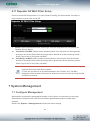
7 System Management
7.1 Configure Management
Administrator could specify geographical location of the system via instructions in this page.
Administrator could also enter new Root and Admin passwords and allow multiple login
methods.
Please click System -> Management and follow the below settings
65
System Information
System Name : Enter a desired name or use the default one.
Description : Provide description of the system.
Location : Enter geographical location information of the system. It helps administrator to
locate the system easier.
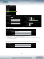
Root Password : Log in as a root user and is allowed to change its own, plus admin user’s
password.
New Password : Enter a new password if desired
Check New Password : Enter the same new password again to check.
66
Login Methods: Only root user can enable or disable system login methods and change
services port.
Enable HTTP : Check to select HTTP Service.
Enable HTTPS : Check to select HTTPS Service
HTTPS Port : The default is 443 and the range is between 1 ~ 65535.
If you already have an SSL Certificate, please click “Upload Key” button to
select the file and upload it.
Enable Telnet : Check to select Telnet Service
Telnet Port : The default is 23 and the range is between 1 ~ 65535.
Enable SSH : Check to select SSH Service
SSH Port : Please The default is 22 and the range is between 1 ~ 65535.
Click “Generate Key” button to generate RSA private key. The “host key
footprint” gray blank will display content of RSA key.
Ping Watchdog : The ping watchdog sets the 100GX-N Device to continuously ping a user
defined IP address (it can be the internet gateway for example). If it is unable to ping under the
user defined constraints, the 100GX-N device will automatically reboot. This option creates a
kind of "fail-proof" mechanism.
Ping Watchdog is dedicated for continuous monitoring of the particular connection to remote
host using the Ping tool. The Ping works by sending ICMP “echo request” packets to the target
host and listening for ICMP “echo response” replies. If the defined number of replies is not
received, the tool reboots the device.
Enable Ping Watchdog : control will enable Ping Watchdog Tool.
IP Address To Ping : specify an IP address of the target host which will be monitored by
Ping Watchdog Tool.
67
Ping Interval : specify time interval (in seconds) between the ICMP “echo requests” are
sent by the Ping Watchdog Tool. Default is 300 seconds.
Startup Delay : specify initial time delay (in seconds) until first ICMP “echo requests” are
sent by the Ping Watchdog Tool. The value of Startup Delay should be at least 60 seconds
as the network interface and wireless connection initialization takes considerable amount
of time if the device is rebooted. Default is 300 seconds.
Failure Count To Reboot : specify the number of ICMP “echo response” replies. If the
specified number of ICMP “echo response” packets is not received continuously, the Ping
Watchdog Tool will reboot the device.
Click Save button to save your changes Click Reboot button to activate your changes
7.2 Configure System Time
System time can be configured via this page, and manual setting or via a NTP server is
supported.
Please click on System -> Time Server and follow the below setting.
68
Local Time : Display the current system time.
Setup Time Use NTP : To synchronize the system time with NTP server.
Time Zone : Select a desired time zone from the drop-down list.
Daylight saving time : Enable or disable Daylight saving.
69
If the system time from NTP server seems incorrect, please verify your network
settings, like default Gateway and DNS settings
U
ser Setup : The management can set time by system time
Date: Setting the date for system.
Time : Setting the time for system.
Click "save" to save your settings. Click Reboot button to activate your changes
7.3 LED Setup
This feature can be turned on/off to control LED lights
7.4 Configure SNMP Setup
SNMP is an application-layer protocol that provides a message format for communication
between SNMP managers and agents. By enabling SNMP function, the administrator can
obtain the system information remotely.
Please click on System -> SNMP and follow the below setting.
70
SNMP v2c Enable: Check to enable SNMP v2c.
ro community : Set a community string to authorize read-only access.
rw community : Set a community string to authorize read/write access.
SNMP v3 Enable:
security.
Check to enable SNMP v3. And supports the highest level SNMP
SNMP ro user : Set a community string to authorize read-only access.
SNMP ro password : Set a password to authorize read-only access.
SNMP rw user : Set a community string to authorize read/write access.
SNMP rw password : Set a password to authorize read/write access.
SNMP Trap : Events such as col will report to an assigned server. d start, interface up &
down, and association & disassociation
71
Community : Set a community string required by the remote host computer that will
receive trap messages or notices send by the system.
IP(1~4) : Enter the IP addresses of the remote hosts to receive trap messages.
Click "save" to save your settings. Click Reboot button to activate your changes
8 Configure Advance Setup
8.1 DMZ (This function must be used WISP mode)
DMZ is commonly work with the NAT functionality as an alternative of Virtual Server(Port
Forwarding) while wanting all ports of DMZ host visible to Internet users. Virtual Server rules
have precedence over the DMZ rule. In order to use a range of ports available to access to
different internal hosts Virtual Server rules are needed.
Please click on Advance -> DMZ and follow the below setting
Service : The DMZ default by “Disable”. Check Enable radial button to enable DMZ.
Automatic Assignment : Enter Internal IP address of DMZ host and only one DMZ host is
supported.
Static Assignment : Enter external and internal IP address of DMZ host. The function only
external IP to Internal IP address
Click "save" to save your settings. Click Reboot button to activate your changes
72
8.2 IP Filter (This function must be used WISP mode)
Allows to create deny or allow rules to filter ingress or egress packets from specific source
and/or to destination IP address on wired (LAN) or Wireless (WAN) ports. Filter rules could be
used to filter unicast or multicast packets on different protocols as shown in the IP Filter Setup.
Important to note that IP filter rules has precedence over Virtual server rules.
Source Address/Mask : Enter desired source IP address and netmask. i.e.
192.168.2.10/32.
Source Port : Enter a port or a range of ports as start:end. i.e. port 20:80
Destination Address/Mask : Enter desired destination IP address and netmask. i.e.
192.168.1.10/32
Destination Port : Enter a port or a range of ports as start:end. i.e. port 20:80
In/Out : Applies to Ingress or egress packets.
Protocol : Supports TCP, UDP or ICMP.
Listen : Click Yes radial button to match TCP packets only with the SYN flag.
Policy : Deny to drop and Pass to allow per filter rules
Interface : The interface that a filter rule applies
Schedule : Can choose to use rule by “Time Policy”
All packets are allowed by default. Deny rules could be added to the filter list to
filter out unwanted packets and leave remaining allowed.
Click “Save” button to add IP filter rule. Total of 20 rules maximum allowed in the IP Filter List.
All rules can be edited or removed from the List. Click Reboot button to activate your changes.
73
When you create rules in the IP Filter List, the prior rules maintain higher priority. To allow
limited access from a subnet to a destination network manager needs to create allow rules first
and followed by deny rules. So, if you just want one IP address to access the system via telnet
from your subnet, not others, the Example 1 demonstrates it, not rules in the Example 2.
Example 1 :
Create a higher priority rule to allow IP address 192.168.2.2 Telnet access from LAN port first,
and deny Telnet access from remaining IP addresses in the same subnet.
Source
Destination
Rule
In/Out Protocol Listen Action Side
IP/Mask
Port IP/Mask
Port
192.168.2.2/
192.168.2.254/
1
22
In
TCP
n
Pass
LAN
32
32
192.168.2.0/
192.168.2.254/
2
22
In
TCP
n
Deny
LAN
24
32
Example 2 :
All Telnet access to the system from the IP addresses of subnet 192.168.2.x works with the rule
1 of Example 2. The rule 2 won’t make any difference.
Source
Destination
Rule
In/Out Protocol Listen Action Side
IP/Mask
Port
IP/Mask
Port
192.168.2.0/
192.168.2.254/
1
22
In
TCP
n
Pass
LAN
24
32
192.168.2.2/
192.168.2.254/
2
22
In
TCP
n
Deny
LAN
32
32
8.3 MAC Filter (This function must be used WISP mode)
Allows to create MAC filter rules to allow or deny unicast or multicast packets from limited
number of MAC addresses. Important and must note. That MAC filter rules have precedence
over IP Filter rules.
Please click on Advance -> MAC Filter Setup and follow the below setting.
74
MAC Filter Rule : By default, it’s “Disable”. Options are Disabled, Only Deny List MAC or
Only Allow List MAC.
Action :
Only Allow List MAC: The wireless clients in the MAC Filter List will be allowed to
access to Access Point; All others will be denied.
Only Deny List MAC : The wireless clients in the MAC Filter List will be denied to
access to Access Point; All others will be allowed.
MAC Address :
Enter MAC address (e.g. aa:bb:cc:00:00:0a) and click “Add” button, then the MAC
address should display in the MAC Filter List.
There are a maximum of 20 clients allowed in this MAC Filter List. The MAC addresses of
the wireless clients can be added and removed to the list using the Add and Delete
buttons.
Schedule : Can choose to use rule by “Time Policy”
Click Reboot button to activate your Setting
8.4 Virtual Server (This function must be used WISP mode)
The “Virtual Server” can also referred to as “Port Forward” as well and used interchangeably.
Resources in the network can be exposed to the Internet users in a controlled manner including
on-line gaming, video conferencing or others via Virtual Server setup. Don’t repeat ports’ usage
to avoid confusion.
Suppose you want to assign ports 21-25 to one FTP, Telnet and SMTP server (A in the
example), and port 80 to another (B in the example). You assign the LAN IP addresses and the
ISP assigns the WAN IP address. The NAT network appears as a single host on the Internet.
Please click on Advance -> Virtual Server and follow the below setting.
75
Service : By Default, It’s “Disable”. Check Enable radial button to enable Virtual Server.
Description : Enter appropriate message for resource sharing via Virtual Server.
Private IP : Enter corresponding IP address of internal resource to share.
Protocol Type : Select appropriate sessions, TCP or UDP, from shared host via multiple
private ports.
Private Port : A port or a range of ports may be specified as start:end; i.e. port 20:80
Public Port : A port or a range of ports may be specified as start:end; i.e. port 20:80
The Private Port and Public Port can be different. However, total number of
ports need to be the same.
Example : Public Port is 11 to 20 and the Private Port can be a 10 ports range.
Click “Add” button to add Virtual Server rule to List. Total of maximum 20 rules are allowed in
this List. All rules can be edited or removed from the List.
Schedule : Can choose to use rule by “Time Policy”
Other Notes
While creating multiple Virtual Server rules, the prior rules have higher priority. The Virtual
server rules have precedence over the DMZ one while both rules exist. Example 1 and 2
demonstrate proper usage of DMZ and Virtual Server rules.
Example 1 :
All connections should be redirected to 192.168.2.12 while DMZ is enabled. Since Virtual
Server rules have precedence over the DMZ rule all connections to TCP port 22 will be directed
to TCP port 22 of 192.168.2.10 and remaining connections to port TCP 20~80 will be
redirected to port TCP 20~80 of 192.168.2.11
Ex.
DMZ Enabled : 192.168.2.12
Rule
Protocol
Private IP
Private Port
Public Port
1
2
TCP
TCP
192.168.2.10
192.168.2.11
22
20:80
22
20:80
Example 2 :
All connections should be redirected to 192.168.2.12 while DMZ is enabled. Since Virtual
Server rules have precedence over the DMZ rule all other connections to TCP port 20~80 will
be redirected to port 20~80 of 192.168.2.11. The rule 2 won’t take effect.
Ex.
DMZ Enabled : 192.168.2.12
Rule
Protocol
Private IP
Private Port
Public Port
1
2
TCP
TCP
192.168.2.11
192.168.2.10
20:80
22
20:80
22
Click Reboot button to activate your changes.
76
8.5 Parental Control (This function must be used WISP
mode)
Parental Control allows you to block or allow specific kinds of Internet usage and traffic, such as
Internet access, designated services, and websites.
Please click on Advance -> Parental Control and follow the below setting.
Rules : Control can be managed by a rule. Use the settings on this screen to establish an
access policy.
Comment : Enter a descriptive name for this rule for identifying purposes.
MAC Address : Enter MAC address in valid MAC address format(xx:xx:xx:xx:xx:xx) and
click “Add” button to add in the MAC group of each rule. Click “Remove” button can
remove MAC address in the group of each rule. There are 10 MAC address maximum
allowed in each rule.
Local / Destination IP : Specify local(LAN)/ destination IP addresses range required for
this rule. If you specify local IP addresses range from 192.168.1.1 to 192.168.2.254. The
matches a range of local IP addresses include every single IP address from the first to
the last, so the example above includes everything from 192.168.1.1 to 192.168.2.254.
Protocol : Select Any or specify protocol(TCP, UDP, ICMP, Content Filter and Application)
from drop-down list. When you select ICMP or Layer 7 Application , the Local(LAN)/
Destination Port can not used.
77
If you want to block websites with specific URL address or using specific keywords, enter
each URL or keyworks in the “Content Filter” field and click “Add” button to add in the
Content Filter list of each rule. Click “Remove” button can remove URL or keywords.
Local Port : Specify local port(LAN port) range required for this rule
Destination Port : Specify destination port range required for this rule
Schedule : Can choose to use rule by “Time Policy”
Service : Check Enable button to activate this rule, and Disable to deactivate.
Click “Add” button to add control rule to List. There are 10 rules maximum allowed in this
Control List. All rules can be removed or edited on the List.
Click Reboot button to activate your changes.
8.6 IP Routing (This function must be used WISP mode)
The IP Routing Settings allows you to configure routing feature in the gateway. The system
supports RIP(Routing Information Protocol ) and OSPF(Open Shortest Path First) dynamic
routing and allows you to manually configure static network routes.
Please click on Advance -> IP Routing and follow the below setting.
78
OSPF Settings :
OSPF Service : By default, it's Disable. To Enable to activated OSPF routing service.
Route ID : The router ID is typically derived by each router from its interface IP address.
Distribute RIP over OSPF : Allow RIP routes will redistributed into OSPF.
RIP Settings :
RIP Service : By default, it's Disable. To Enable to activated RIP routing service.
Side : Specify desired interface WAN, LAN for sending and receiving of RIP packets.
Distribute OSPF over RIP : Allow OSPF routes redistributed into RIP.
Change these settings as described here and click Save button to save your changes. Click
Reboot button to activate your changes
79
Static Routing Setup :
Service : Click Enable to activated static routing.
Destination Net/Mask : Specify desired destination IP network address with format of
A.B.C.D/M
Via : Select a next hop of Gateway or Interface to the destination IP network.
Gateway : Enter gateway IP address
Interface : Choose the interface via LAN or WAN
Protocol : Set static routing rule to RIP or OSPF network. Select RIP to associate specific
network on RIP routing process. Select OSPF to associate specific network with the
specified area on OSPF routing process
Click “Save” button to add Routing rule to List. There are maximum 20 rules allowed in this List.
All rules can be edited or removed on the List. Click Reboot button to activate your changes.
8.7 Time Policy
Administrator can define time policy for Service Domain, IP Filtering, MAC Filtering and Virtual
Server. There are 10 policy can be defined.
Please click on Advance Time Policy to enter Time Policy Setup page.
80
Policy : There are 10 Policy can be selected.
Schedule Rule : Select desired schedule for this policy.
On Schedule : Execution is based on schedule
Out of Schedule : Execution is based outside the schedule
Click “Save Action” button to complete
Time Schedule : Day of week setting by timetable
Click “Save” button to add schedule to policy. There are 10 schedule maximum allowed in the
each time policy. All schedule can be edited or removed in the each time policy. Click Reboot
button to activate your changes.
81
9 Configure Utilities Setup
9.1 Profile setting
The Function is backup current configuration, restore prior configuration or reset back to factory
default configuration can be executed via this page.
Please click on Utilities -> Profile Setting and follow the below setting
Save Settings to PC : Click Save button to save the current configuration to a local disk.
Load Settings from PC : Click Browse button to locate a configuration file to restore, and
then click Upload button to upload.
Reset To Factory Default : Click Default button to reset back to the factory default
settings and expect Successful loading message. Then, click Reboot button to activate.
82
9.2 Firmware Upgrade
Firmware is the main software image that system needs to respond to requests and to manage
real time operations. Firmware upgrades are sometimes required to include new features or
bugs fix. It takes around 2 minutes to upgrade due to complexity of firmware. To upgrade
system firmware, click Browse button to locate the new firmware, and then click Upgrade button
to upgrade.
To prevent data loss during firmware upgrade, please back up current settings
before proceeding
Do not interrupt during firmware upgrade including power on/off as this may
damage system.
Firmware Information :Show currently the 100GX-N of system software version and
software date
Upgrade firmware : The upgrade firmware will support via local PC and TFTP Server and
HTTP URL to upgrade system
83
9.3 Network Utility
The administrator can diagnose network connectivity via the PING or TRACEROUTE utility.
Please click on Utilities -> Network Utility and follow the below setting.
Ping : This utility will help ping other devices on the network to verify connectivity. Ping
utility, using ICMP packets, detects connectivity and latency between two network nodes.
As result of that, packet loss and latency time are available in the Result field while running
the PING test.
IP/Domain : Enter desired domain name, i.e. www.google.com, or IP address of the
destination, and click ping button to proceed. The ping result will be shown in the Result
field.
Count : By default, it’s 5 and the range is from 1 to 50. It indicates number of connectivity
test.
Traceroute
Allows tracing the hops from the 100GX-N device to a selected outgoing IP address. It should
be used for the finding the route taken by ICMP packets across the network to the destination
host. The test is started using the Start button, click Stop button to stopped test.
Destination Host : Specifies the Destination Host for the finding the route taken by ICMP
packets across the network.
MAX Hop : Specifies the maximum number of hops( max time-to-live value) trace route
will probe.
9.4 Reboot
This function allows user to restart system with existing or most current settings when changes
are made. Click Reboot button to proceed and take around three minutes to complete.
84
The System Overview page appears upon the completion of reboot.
10 Configure Status
10.1 Overview
Detailed information on System, Network can be reviewed via this page
System Information : Display the information of the system.
Device Information : Display the information of the Port link.
CPU Information : Display the information of the system CPU
Memory information : Display the information of the system Memory.
Networking Information : Display the information of the network.
Wireless Clients : Display the information of the wireless user link.
85
10.2 DHCP Client (This function must be used WISP mode)
The administrator can view status of all DHCP Client Users on each DHCP Server.
Please click on Status DHCP Client to look DHCP information.
DHCP Server Status : Display the information of the DHCP Server.
DHCP Client List : Display the information of the DHCP Client users.
10.3 Extra Info
Users could pull out information such as Route table, ARP table, MAC table, Bridge table or
STP available in the drop-down list from system. The “Refresh” button is used to retrieve latest
table information.
Netstat Information : Select “NetStatus Information” on the drop-down list, the
connection track list should show-up. NetStatus will show all connection track on the
system, the information include Protocol, Live Time, Status, Source/Destination IP
address and Port. (This function must be used WISP mode)
86
Route Information : Select “Route Information” on the drop-down list to display route
table. 100GX-N could be used as a L2 or L3 device. It doesn’t support dynamic routing
protocols such as RIP or OSPF. Static routes to specific hosts, networks or default
gateway are set up automatically according to the IP configuration of system's interfaces.
When used as a L2 device, it could switch packets and, as L3 device, it’s capable of being
a gateway to route packets inward and outward.
ARP Table Information : Select “ARP Table Information” on the drop-down list to display
ARP table.
ARP associates each IP address to a unique hardware address (MAC) of a device. It is
important to have a unique IP address as final destination to switch packets to.
Bridge table information : Select “Bridge Table information” on the drop-down list to
display bridge table.
87
Bridge table will show Bridge ID and STP's Status on the each Ethernet bridge and its attached
interfaces, the Bridge Port should be attached to some interfaces (e.g. eth2, ra0~ra7 and
wds0~wds3).
Bridge MACs Information : Select “Bridge MACs Information” on the drop-down list to
display MAC table.
This table displays local MAC addresses associated with wired or wireless interfaces, but also
remember non-local MAC addresses learned from wired or wireless interfaces.
Ageing timers will be reset when existing MAC addresses in table are learned again or added
when new MAC addresses are seen from wired or wireless interfaces as well. When time runs
out for a particular entry, it will be pruned from the table. In that situation, switching packet to
that particular MAC address will be dropped.
Bridge STP Information : Select “Bridge STP Information” on the drop-down list to
display a list of bridge STP information.
88
10.4 Event Log
The Event log displays system events when system is up and running. Also, it becomes very
useful as a troubleshooting tool when issues are experienced in system.
Time : The date and time when the event occurred.
Facility : It helps users to identify source of events such “System” or “User”
Severity : Severity level that a specific event is associated such as “info”, “error”,
“warning”, etc.
Message : Description of the event.
Click “Refresh” button to renew the log
Click “Clear” button to clear all the record.
89
Appendix A. WEB GUI Valid Characters
Table B WEB GUI Valid Characters
Block
Field
Valid Characters
LAN
IP Address
IP Format; 1-254
IP Netmask
128.0.0.0 ~ 255.255.255.252
IP Gateway
IP Format; 1-254
Primary DNS
IP Format; 1-254
Secondary DNS
IP Format; 1-254
Hostname
Length : 32
0-9, A-Z, a-z
~!@#$%^*()_+-{}|:<>?[]/;`,
WAN
Manual MAC Address
12 HEX chars
IP Address
IP Format; 1-254
IP Netmask
128.0.0.0 ~ 255.255.255.252
IP Gateway
IP Format; 1-254
Hostname
Length : 32
0-9, A-Z, a-z
~!@#$%^*()_+-{}|:<>?[]/;`,
.=
Password
Length : 32
0-9, A-Z, a-z
~!@#$%^*()_+-{}|:<>?[]/;`,
.=
MTU
576 ~ 1492 for PPPoE; 1400 ~ 1460 for PPTP
Idle Time
0 ~ 60 minutes
Primary DNS
IP Format; 1-254
Secondary DNS
IP Format; 1-254
Hostname
Length : 32
0-9, A-Z, a-z
@-_.
User Name
Password
Length : 32
0-9, A-Z, a-z
~!@#$%^*()_+-{}|:<>?[]/;`,
Start IP
IP Format; 1-254
End IP
IP Format; 1-254
DNS1 IP
IP Format; 1-254
DNS2 IP
IP Format; 1-254
WINS IP
IP Format; 1-254
User name
DDNS
DHCP Server
.=
90
.=
Domain
Lease Time
Length : 32
0-9, A-Z, a-z
~!@#$%^*()_+-{}|:<>?[]/;`,
.=
600 ~ 99999999
Table B WEB GUI Valid Characters (continued)
Block
Field
Valid Characters
Management
System Name/ Location
Length : 32
0-9, A-Z, a-z
Space
~!@#$%^*()_+-{}|:<>?[]/;`,
SNMP
Description
32 chars
Password
Length : 4 ~ 30
0-9, A-Z, a-z
~!@#$%^*()_+-{}|:<>?[]/;`,
.=
HTTP/ HTTPS Port
1 ~ 65535
Telnet/ SSH Port
1 ~ 65535
RO/RW community
Length : 32
0-9, A-Z, a-z
~!@#$%^*()_+-{}|:<>?[];`,
.=
Length : 31
0-9, A-Z, a-z
~!@#$%^*()_+-{}|:<>?[];`,
.=
Length : 8 ~ 32
0-9, A-Z, a-z
~!@#$%^*()_+-{}|:<>?[];`,
.=
Length : 32
0-9, A-Z, a-z
~!@#$%^*()_+-{}|:<>?[];`,
.=
RO/RW user
RO/RW password
Community
IP
IP Format; 1-254
General Setup
Tx Power
1-100 %
Wireless Profile
Profile Name
32 chars
ESSID
Length : 31
Space
0-9, A-Z, a-z
~!@#$%^*()_+-{}|:<>?[]/;`,
Advanced Setup
.=
WEP Key
10, 26 HEX chars or 5, 13 ASCII chars
Pre-shared Key
8 ~ 63 ASCII chars; 64 HEX chars
Beacon Interval
20 ~ 1024
Date Beacon Rate
1 ~ 255
Fragment Threshold
256 ~ 2346
RTS Threshold
1 ~ 2347
91
.=
Table B WEB GUI Valid Characters (continued)
Block
Field
Valid Characters
Virtual AP Setup
ESSID
Length : 31
Space
0-9, A-Z, a-z
~!@#$%^*()_+-{}|:<>?[]/;`,
Maximum Clients
1 ~ 32
VLAN ID
1 ~ 4094
WEP Key
10, 26 HEX chars or 5, 13 ASCII chars
Group Key Update Period
>=60 seconds
PMK Cache Period
> 0 minute
Pre-Shared Key
8 ~ 63 ASCII chars; 64 HEX chars
Radius Server IP
IP Format; 1-254
Radius Port
1 ~ 65535
Shared Secret
8 ~ 64 characters
Session Timeout
>= 60
WEP Key
10, 26 HEX chars or 5, 13 ASCII chars
TKIP Key
8 ~ 63 ASCII chars; 64 HEX chars
AES Key
8 ~ 63 ASCII chars; 64 HEX chars
Peer's MAC Address
12 HEX chars
Description
32 chars
Source Address
IP Format; 1-254
Source Mask
0 ~ 32
Source Port
1 ~ 65535
Destination Address
IP Format; 1-254
Destination Mask
0 ~ 32
Destination Port
1 ~ 65535
MAC Filter
MAC address
MAC Format; 12 HEX chars
Virtual Server
Description
32 chars
Private IP
IP Formate; 1-254
Private/ Public Port
1 ~ 65535
DMZ
IP Address
IP Format; 1-254
QoS/
Comment
32 chars
WDS Setup
IP Filter
92
seconds; 0 is disable
.=
Block
Field
Valid Characters
Parental Control
MAC Address
MAC Format; 12 HEX chars
Local/ Destination IP
IP Formate; 1-254
Local/ Destination Port
1 ~ 65535
Upload & Download
8 ~ 8192 digital number
Appendix B. MCS Data Rate
The table below shows the relationships between the variables that allow for the maximum data rate
Table C MCS Data Rate
Data Rate (Mb/s)
Channel Bandwidth = 20
Channel Bandwidth = 40
Long Guard
Interval
Short Guard
Interval
Long Guard
Interval
Short Guard
Interval
BPSK
6.5
7.2
13.5
15.0
1
QPSK
13.0
14.4
27.0
30.0
2
QPSK
19.5
21.7
40.5
45.0
3
16-QAM
26.0
28.9
54.0
60.0
4
16-QAM
39.0
43.3
81.0
90.0
5
64-QAM
52.0
57.8
108.0
120.0
6
64-QAM
58.5
65.0
121.5
135.0
7
64-QAM
65.0
72.2
135.0
157.5
8
BPSK
13.0
14.4
27.0
30.0
9
QPSK
26.0
28.9
54.0
60.0
10
QPSK
39.0
43.3
81.0
90.0
11
16-QAM
52.0
57.8
108.0
120.0
12
16-QAM
78.0
86.7
162.0
180.0
13
64-QAM
104.0
115.6
216.0
240.0
14
64-QAM
117.0
130.0
243.0
270.0
15
64-QAM
130.0
114.4
270.0
300.0
MCS
Index
Modulation
0
Note :
When MCS=32, only Short Guard Interval option is supported, Channel Bandwidth=20 is not
supported. If Channel Bandwidth=40, the HT duplicate 6Mbps.
93
When MCS=0~7(One Tx Stream), Guard Interval and Channel Bandwidth are supported
When MCS=8~15(Two Tx Stream), Guard Interval and Channel Bandwidth are supported
Appendix C. Specifications
Hardware Specifications
Standards Conformance
Ethernet Configuration
Telephone Configuration
LED Indicators
IEEE 802.11 b/g/n compliant
IEEE 802.3 / IEEE 802.3u
IEEE 802.3af Power over Ethernet
IEEE 802.11i Preauth (PMKSA Cache )
IEEE 802.11d Multi country roaming
IEEE 802.1Q Tag VLAN
IEEE802.11f IAPP
IEEE802.11e WMM
10/100BASE-TX auto-negotiation Ethernet RJ-45 connector) ;
Auto MDI/MDI-X WAN * 1 , LAN * 1
RJ-11 Pass Through In x1 connector , Out x1 connector
( Power / Network Access ) LED x 1,
Wireless Specifications
Data Transfer Rate
Operating Channels
Transmit Power Variation
IEEE802.11b : 1 / 2 / 5.5 / 11Mbps (auto sensing)
IEEE801.11g : 6/ 9/ 12/ 18/ 24/ 36/ 48/ 54Mbps
IEEE802.11n : 150Mbps (Tx), 150Mbps (Rx)
2.412 ~ 2.462GHz (USA)
2.412 ~ 2.484GHz (Japan)
2.412 ~ 2.472GHz (Europe ETSI)
2.457 ~ 2.462 GHz (Spain)
2.457 ~ 2.472 GHz (France)
IEEE802.11b/g/n : 20/40MHz
CSMA / CA with ACK
IEEE 802.11b: DSSS (DBPK,DQPSK,CCK)
IEEE 802.11g/n: OFDM (64-QAM,16-QAM,QPSK,BPSK)
IEEE 802.11b/g/n:
Max : 29 ± 1 dBm
Receiver Sensitivity
Max : -96dBm
Frequency Range
Channel Spacing
Media Access Protocol
Modulation Method
94
Environmental & Mechanical Characteristics
Operating Temperature
Storage Temperature
Operating Humidity
Storage Humidity
Antenna
Form Factor
System Power Consumption
Input Power Require
Dimensions ( W x H x D )
Unit Weight
Certifications
-25 °C ~ 55 °C
-25 °C ~ 65 °C
5% to 90% Non-Condensing
Build in 1x 2.5dBi RF Antenna
Wall / In Wall
8 Watt Max.
803.3af 48V PoE Ethernet Interface Power In
Main Unit : 52 x 76.2 x 35mm
Faceplate Set : 70 x120x10 mm(US-Type )
Faceplate Set : 86 x 88 x10 mm(EU-Type )
72.5g
CE ,FCC,NCC、BSMI 、ROHS compliant
95