1
Owners Manual
© 2001 E-MU Systems
All Rights Reserved
FI12700 Rev. A
E-MU World Headquarters
E-MU Systems
1600 Green Hills Road
Scotts Valley, CA USA
95067-0015
Telephone: 831-438-1921
Fax: 831-438-8612
Internet: www.emu.com
Europe, Africa, Middle East
E-MU Systems
Suite 6, Adam Ferguson House
Eskmills Industrial Park
Musselburgh, East Lothian
Scotland, EH21 7PQ
Tel: +44 (0) 131-653-6556
Fax: +44 (0) 131-665-0473
Important Notice:
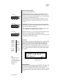
In order to obtain warranty service on your PX-7 unit, the serial number sticker
must be intact and you must have a sales receipt or other proof of purchase. If
there is no serial number sticker on the PX-7, please contact E-MU Systems at
once.
This product is covered under one or more of the following U.S. patents:
4,404,529; 4,506,579; 4,699,038; 4,987,600; 5,013,105; 5,072,645;
5,111,727; 5,144,676; 5,170,367; 5,248,845; 5,303,309; 5,317,104;
5,342,990; 5,430,244 and foreign patents and/or pending patents. All other
trademarks belong to their respective companies. Specifications and features are
subject to change without notice.
PX-7 Owners Manual i
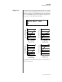
Table of Contents
Introduction ............................................................................. 1
Product Description .......................................................................................1
Important Safety Instructions .................................................. 3
Setup ...................................................................................... 13
Unpacking ....................................................................................................13
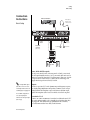
Connection Instructions..............................................................................14
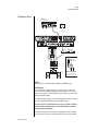
Basic Setup ..............................................................................................14
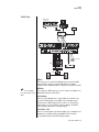
Studio Setup ............................................................................................15
Performance Setup ..................................................................................16
Power Down Sequence ............................................................................17
Rack Mounting PX-7 ...............................................................................17
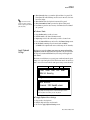
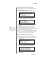
Instant Gratification ............................................................... 19
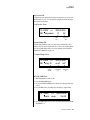
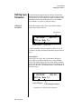
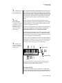
Playing Patterns & Songs ........................................................................19
Playing Songs ..........................................................................................21
Playing Demo Sequences ........................................................................22
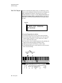
Auditioning Presets .................................................................................22
Selecting and Quick Editing Presets .......................................................23
Exploring the Master Arpeggiator ...........................................................25
Multi-Channel Arpeggiator ....................................................................26
Time to Save? .......................................................................................27
Basic Operations .................................................................... 29
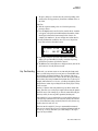
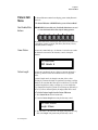
Power Switch ...........................................................................................29
Volume Control ......................................................................................29
12VDC Lamp ..........................................................................................29
Mode/View Buttons .....................................................................................30
Track/Channel +/- Buttons .....................................................................31
Data Entry Control .................................................................................31
Left/Right Cursor Buttons .......................................................................31
LED View Select Section...............................................................................31
ii E-MU Systems
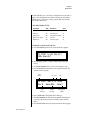
Sequencer Controls...................................................................................... 32
Stop Button ............................................................................................. 32
Play Button ............................................................................................. 32
Record Button ......................................................................................... 32
Song Record modes (from Song mode) .............................................. 32
Pattern Record modes (from Pattern mode) ....................................... 32
Tap Tempo ............................................................................................. 32
Edit Section .................................................................................................. 33
Song Edit Button .................................................................................... 33
Pattern Edit Button ................................................................................. 33
Preset Edit Button ................................................................................... 33
Global Button ......................................................................................... 33
Controllers Button .................................................................................. 33
Arpeggiator Button ................................................................................. 34
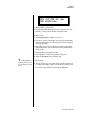
Real-time Controller Knobs ......................................................................... 35
Knob Functions ...................................................................................... 36
Quick Edit mode ................................................................................. 36
Programmable Knobs mode ................................................................ 37
Multichannel Volume Knobs .............................................................. 37
Multichannel Pan Knobs .................................................................... 38
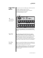
Trigger/Mute Buttons................................................................................... 39
Trigger Mode ........................................................................................... 39
Preset Menu Jump Keys .......................................................................... 39
Touchstrip, Transpose, Keypads & Glide ..................................................... 40
Touchstrip Hold ...................................................................................... 40
Transpose Buttons .................................................................................. 40
Rubber Keypads ...................................................................................... 40
Glide Button ........................................................................................... 40
Erase Button ............................................................................................ 41
Repeat Button ......................................................................................... 41
Preset Screen ................................................................................................ 42
MIDI Channel Selection ......................................................................... 42
Preset Selection ....................................................................................... 42
Channel Volume .................................................................................... 43
Channel Pan ........................................................................................... 44
Channel Arpeggiator .............................................................................. 44
Sound Navigator .......................................................................................... 45
Preset Category ....................................................................................... 45
Instrument Category .............................................................................. 45
Sequencer ...............................................................................47
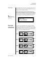
Overview ...................................................................................................... 48
Definitions ................................................................................................... 49
Events ..................................................................................................... 49
Tracks ...................................................................................................... 49
Patterns ................................................................................................... 49
Pattern Recording & Editing ............................................................... 50
The Asterisk ......................................................................................... 50
PX-7 Owners Manual iii
Standard MIDI Files .............................................................................50
Songs .......................................................................................................51
Song Record Modes .............................................................................51
Pattern Mode................................................................................................52
Pattern Play .............................................................................................52
Restart/Pattern Fire Key ..........................................................................53
Realtime Recording .................................................................................53
Preparing to Record a Pattern .................................................................53
Input Quantize ........................................................................................54
Count In ..................................................................................................55
First Note Record .....................................................................................56
Pattern Length ........................................................................................56
Metronome .............................................................................................57
Recording a Pattern .................................................................................57
Automatic Channel Assignment .........................................................61
Replace Record ........................................................................................62
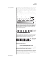
Grid Recording ........................................................................................63
What is Grid Recording? .....................................................................63
Step Time Recording ...............................................................................67
Note Value/Number of Ticks ............................................................68
Pattern Edit Menu ........................................................................................70
Track Enable/Mute Buttons ....................................................................70
Name Pattern ..........................................................................................70
Pattern Length ........................................................................................70
Setting Meter (Time Signature) ...............................................................71
Metronome .............................................................................................72
Loop Section ...........................................................................................73
In Pattern Mode ..................................................................................73
In Song Mode ......................................................................................74
Quantize ..................................................................................................75
Quantize Parameters ...........................................................................75
More about Swing ...............................................................................76
Scale/Shift Start Times ............................................................................77
Tips & Tricks ........................................................................................77
Scale/Shift Duration ................................................................................78
Thin Events .............................................................................................79
Erase Events ............................................................................................81
Transpose ................................................................................................82
Scale/Shift Velocity .................................................................................83
Extend Sequence Data To .......................................................................84
Erase Track ..............................................................................................85
Cut Track to Clipboard ...........................................................................86
Copy Track to Clipboard ........................................................................87
Paste Clipboard to Track .........................................................................88
Apply Clipboard Settings ........................................................................89
Explode/Combine Tracks ........................................................................90
Combine Tracks ...................................................................................90
Explode Tracks .....................................................................................90
Channel Assign .......................................................................................92
iv E-MU Systems
Multichannel Track Recording ............................................................... 93
Note List Editor ....................................................................................... 95
Event List Editor ..................................................................................... 96
Continuous Controller Edit ................................................................ 96
Continuous Controller Screen ............................................................ 96
Pitch Strip Edit .................................................................................... 96
Pitch Strip Screen ................................................................................ 96
Poly Pressure Edit ................................................................................ 97
Poly Pressure Screen ............................................................................ 97
Program Change Edit .......................................................................... 97
Program Change Screen ...................................................................... 97
The Conductor Track .............................................................................. 99
Conductor Track Screens .................................................................... 99
Revert to Saved Pattern ......................................................................... 101
Song Mode ................................................................................................. 102
Song Play .............................................................................................. 102
Song Step Recording ............................................................................. 102
Realtime Song Recording ...................................................................... 106
Song Edit Menu ......................................................................................... 109
Song Name ............................................................................................ 109
Event Source ......................................................................................... 109
Setting Meter (Time Signature) ............................................................ 110
Metronome ........................................................................................... 111
Quantize ............................................................................................... 111
Scale/Shift Start Times .......................................................................... 112
Scale/Shift Duration ............................................................................. 112
Thin Events ........................................................................................... 112
Erase Events .......................................................................................... 113
Transpose .............................................................................................. 114
Scale/Shift Velocity ............................................................................... 115
Cut Track to Clipboard ......................................................................... 116
Copy Track to Clipboard ...................................................................... 117
Paste Clipboard to Track ....................................................................... 118
Song Channel Assign ............................................................................ 119
Note List Editor ..................................................................................... 120
Event List Editor ................................................................................... 121
Continuous Controller Edit .............................................................. 121
Continuous Controller Screen .......................................................... 121
Pitch Strip Edit .................................................................................. 121
Pitch Strip Screen .............................................................................. 121
Poly Pressure Edit .............................................................................. 122
Poly Pressure Screen .......................................................................... 122
Program Change Edit ........................................................................ 122
Program Change Screen .................................................................... 122
Revert to Saved Song ............................................................................ 123
Live Performance Features ......................................................................... 124
XMix ..................................................................................................... 124
Using the Repeat Button for Live Performance .................................... 126
Mute Hold ............................................................................................. 126
Loop Section ...................................................................................... 127
PX-7 Owners Manual v
Restart/Pattern Fire Key .....................................................................127
Pattern Change Tempo Hold ............................................................127
Event Timing..............................................................................................128
Track Priority .....................................................................................128
Applications ...............................................................................................129
Using the Internal Sequencer with an External MIDI Keyboard .........129
How to Record the Audition Riffs ........................................................130
Controllers Menu ................................................................. 131
Realtime Control Functions.......................................................................132
Keyboard Transpose ..............................................................................132
Keyboard Channel ................................................................................132
Aftertouch Curves .................................................................................132
Local Control On/Off ...........................................................................133
Footswitch Jack Function .....................................................................134
Trigger Buttons Function ......................................................................135
Trigger Buttons .....................................................................................136
Trigger Button Select .........................................................................136
Latch on/off .......................................................................................136
MIDI Key ...........................................................................................136
MIDI Channel ...................................................................................136
Destination ........................................................................................136
Key Velocity .......................................................................................136
Triggers Pattern Select ...........................................................................137
Trigger Mode Quick Select ....................................................................138
Programmable Knobs ............................................................................138
Knob Preset Quick-Edit .........................................................................139
Real-time Controller Assignment .........................................................139
MIDI Footswitch Assign ........................................................................141
Tempo Controller .................................................................................141
Global Menu ........................................................................ 143
Multisetups.................................................................................................144
Restoring Multisetups ...........................................................................144
Multisetup Name ..................................................................................145
Saving Multisetups ................................................................................145
Defining Global Parameters .......................................................................146
Transpose/Tune .....................................................................................146
Bend Range ...........................................................................................146
Velocity Curve ......................................................................................147
Mix Output ...........................................................................................148
Master Effects .............................................................................................150
Effects Mode ..........................................................................................150
Effects Multi Mode Control ..................................................................150
Master FXA Algorithm ..........................................................................151
A Effect Types ....................................................................................151
FXA Parameters: Decay/HF Damping FxB -> FxA .................................152
FXA Send Amounts ...............................................................................152
vi E-MU Systems
Master FXB Algorithm .......................................................................... 152
B Effect Types .................................................................................... 153
FXB Parameters: Feedback/LFO Rate Delay Time ................................. 153
FXB Send Amounts ............................................................................... 153
Miscellaneous Parameters.......................................................................... 154
Edit All Layers Enable ........................................................................... 154
User Key Tuning ................................................................................... 154
Output Format ...................................................................................... 154
Screen Viewing Angle ........................................................................... 155
MIDI Menu ............................................................................157
Base Tempo ........................................................................................... 158
Pattern Change Tempo Hold ................................................................ 158
Rechannelize Input ............................................................................... 159
Knobs Output MIDI .............................................................................. 160
Transmit MIDI Clock ............................................................................ 160
External Song Start/Stop ....................................................................... 161
Merge MIDI In to MIDI Out ................................................................. 161
MIDI In Channels ................................................................................. 161
MIDI Enable .......................................................................................... 162
Receive Program Change ...................................................................... 162
MIDI Program Change -> Preset ........................................................... 163
MIDI SysEx ID ....................................................................................... 164
MIDI SysEx Packet Delay ...................................................................... 164
Send MIDI System Exclusive Data ........................................................ 164
MIDI Mode ........................................................................................... 166
Programming Basics .............................................................167
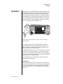
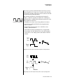
Modulation ................................................................................................ 168
Modulation Sources ................................................................................... 169
Random Sources ................................................................................... 170
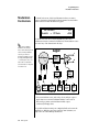
Modulation PatchCords............................................................................. 170
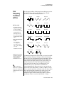
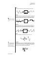
Envelope Generators.................................................................................. 171
Tempo-based Envelopes .................................................................... 172
Envelope Repeat ................................................................................ 172
Low Frequency Oscillators (LFOs) ............................................................. 173
Clock Modulation...................................................................................... 174
Modulation Destinations........................................................................... 176
Modulation Processors............................................................................... 177
Preset Modulation Processors .................................................................... 179
Using the Modulation Processors ......................................................... 181
More Examples ..................................................................................... 183
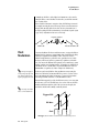
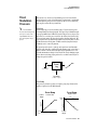
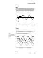
Dynamic Filters.......................................................................................... 185
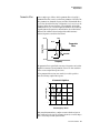
What is a Filter? .................................................................................... 186
Parametric Filters .................................................................................. 189
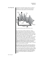
The Z-Plane Filter .................................................................................. 190
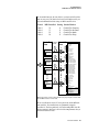
Signal Flow................................................................................................. 191
PX-7 Owners Manual vii
MIDI Channels & Real-time Controls .......................................................192
Bank Select Commands ........................................................................194
Stereo Mix Outputs ....................................................................................194
Preset Edit Menu .................................................................. 197
Preset Name ..........................................................................................198
Four Layer Architecture..............................................................................198
Selecting Layers .....................................................................................199
Defining Layer Parameters .........................................................................200
Selecting an Instrument ........................................................................200
Sound Navigator ................................................................................200
Defining Key Range ..............................................................................201
Defining the Velocity Crossfade Range ................................................203
Defining the Real-time Crossfade Range ..............................................205
Transposing the Instrument .................................................................208
Tuning ...................................................................................................209
Background: Transpose vs. Coarse Tuning .......................................209
Amplifier ...............................................................................................209
Volume Envelope ..................................................................................210
Selecting the Mode ............................................................................210
Defining the Volume Envelope .........................................................211
Chorusing the Layer .............................................................................212
Sound Start Offset, Delay & Key-up Layer ............................................212
Non-Transpose Mode ............................................................................214
Solo Mode .............................................................................................214
Assign Group .........................................................................................215
Glide ......................................................................................................216
Z-Plane Filters ........................................................................................217
PX-7 Filter Types ...................................................................................217
Filter Types ........................................................................................217
Filter Parameters ................................................................................219
Filter Envelope ......................................................................................220
Defining the Filter Envelope .............................................................221
Auxiliary Envelope ................................................................................221
Low Frequency Oscillators (LFOs) ........................................................222
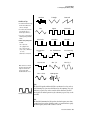
Shape .................................................................................................222
Sync ...................................................................................................223
Rate ....................................................................................................223
Delay ..................................................................................................225
Variation ............................................................................................225
PatchCords ............................................................................................226
Modulator Polarity ............................................................................227
Pitch Bend Range ..................................................................................229
Mix Output ...........................................................................................229
Common Preset Parameters.......................................................................230
Preset Effects .........................................................................................230
FXA Algorithm ......................................................................................232
A Effect Types ....................................................................................232
FXA Parameters .....................................................................................233
viii E-MU Systems
FXA Send Amounts ............................................................................... 233
FXB Algorithm ...................................................................................... 233
B Effect Types .................................................................................... 233
FXB Parameters ..................................................................................... 234
FXB Send Amounts ............................................................................... 234
Preset Patchcords .................................................................................. 234
Initial Controller Amount .................................................................... 236
Keyboard Tuning .................................................................................. 237
Preset Links ........................................................................................... 239
Preset Tempo Offset .............................................................................. 239
Audition Riff Selection ......................................................................... 240
Play Solo Layers .................................................................................... 240
Arpeggiator/Beats Menu ......................................................241
Arpeggiators ............................................................................................... 242
Arp Controllers ..................................................................................... 243
Arpeggiator Resolution ...................................................................... 243
Arpeggiator Extension ....................................................................... 243
Arpeggiator Velocity .......................................................................... 243
Arpeggiator Gate ............................................................................... 243
Arpeggiator Interval .......................................................................... 243
Master Arpeggiator Parameters .................................................................. 243
Status ..................................................................................................... 244
Mode ..................................................................................................... 244
Note Value ............................................................................................ 245
Arpeggiator Pattern Speed .................................................................... 245
Pattern .................................................................................................. 245
Velocity ................................................................................................. 246
Gate Time ............................................................................................. 246
Extension Count ................................................................................... 247
Extension Interval ................................................................................ 247
Sync ...................................................................................................... 248
Pre-Delay ............................................................................................... 248
Duration ............................................................................................... 249
Post-Delay ............................................................................................. 249
Recycle .................................................................................................. 250
Keyboard Thru ...................................................................................... 250
Latch ..................................................................................................... 250
Arp/Riff MIDI Out ................................................................................ 251
MIDI Song Start .................................................................................... 251
Send MIDI System Exclusive Data ............................................................. 252
Editing a User Arpeggiator Pattern ....................................................... 252
Pattern Step Number ............................................................................ 253
Key ........................................................................................................ 253
Key Offset .......................................................................................... 253
Tie ...................................................................................................... 254
Rest .................................................................................................... 254
Skip .................................................................................................... 254
End .................................................................................................... 254
PX-7 Owners Manual ix
Velocity .................................................................................................254
Duration ................................................................................................255
Repeat ....................................................................................................255
User Pattern Name ................................................................................255
Multichannel Arpeggiating ...................................................................256
Beats ...........................................................................................................257
Beats Mode ............................................................................................259
Status .................................................................................................259
Beats Channel ....................................................................................259
Trigger Channel .................................................................................259
Beats Controllers ...................................................................................262
Beat Velocity Group 1-4 ....................................................................262
Beat Xpose Group 1-4 ........................................................................262
Beat Busy ............................................................................................262
Beat Variation.....................................................................................263
Beats Keys/Trigger Layout .....................................................................264
1-Bar Trigger Option .........................................................................264
Beats Keys Offset ...................................................................................265
Beats Part Velocity ................................................................................265
Beats Part Transpose .............................................................................266
Beats Part Group ...................................................................................267
Master Riff .............................................................................................267
Riff Tempo ............................................................................................268
Riff Controllers .....................................................................................268
Effects ................................................................................... 269
Effects Overview.........................................................................................269
The Effects Sends ..................................................................................269
Effect Types ................................................................................................271
Effect Parameters ...................................................................................271
Decay .................................................................................................272
High Frequency Damping .................................................................272
Feedback ............................................................................................272
LFO Rate ............................................................................................272
Delay ..................................................................................................272
Effects Programmed in the Preset ..............................................................273
Master Effects .............................................................................................274
Effects Mode ..........................................................................................276
Flexible Effects Control .........................................................................276
Using the Effects Channel Settings in Multi Mode ..........................278
Effect B Into Effect A .............................................................................278
General Effect Descriptions........................................................................280
Reverb ...................................................................................................280
Chorus ...................................................................................................281
Doubling ...............................................................................................281
Slapback ................................................................................................281
Stereo Flanger ........................................................................................281
Delay .....................................................................................................282
x E-MU Systems
Stereo Delay .......................................................................................... 282
Panning Delay ...................................................................................... 282
Dual Tap ............................................................................................... 282
Vibrato .................................................................................................. 282
Distortion ............................................................................................. 282
Save/Copy Menu ..................................................................283
Save Pattern .......................................................................................... 283
Saving a Preset ...................................................................................... 284
Saving a Song ........................................................................................ 284
Copying Information ................................................................................ 285
Copy Preset ........................................................................................... 285
Copy Layer ............................................................................................ 285
Copy PatchCords .................................................................................. 286
Copy Preset PatchCords ....................................................................... 287
Copy Arpeggiator Settings .................................................................... 287
Copy Arpeggiator Pattern ..................................................................... 288
Copy Preset Bank .................................................................................. 288
Copy Sequencer Pattern ....................................................................... 289
Copy Song ............................................................................................ 289
Sound Authoring ....................................................................................... 290
Rename Flash SIMM ............................................................................. 291
Duplicate Flash ..................................................................................... 292
Compact Flash Now!.................................................................................. 293
Create Random Preset................................................................................ 293
Preset Programming .............................................................295
Editing Presets............................................................................................ 295
Changing the Instrument .................................................................... 295
Changing the Tuning of an Instrument .............................................. 296
Chorus .................................................................................................. 297
Volume Envelope ................................................................................. 297
Working with Filters ............................................................................. 299
Adding the Filter Envelope ............................................................... 301
Changing Filter Types ....................................................................... 303
Envelope Repeat ................................................................................ 303
Practice Modulating .............................................................................. 304
Troubleshooting ................................................................................... 305
Linking Presets ........................................................................................... 306
Appendix ...............................................................................307
Front Panel Knob Functions ...................................................................... 307
Knob Controller Descriptions .............................................................. 308
Presets ........................................................................................................ 308
PX-7 Preset Categories .......................................................................... 308
Preset Notes .......................................................................................... 309
Linked Presets..................................................................................... 309
PX-7 Owners Manual xi
Default and Template Presets ............................................................309
Retrigger/Strip ....................................................................................309
Up Layer ............................................................................................309
Play Through .....................................................................................309
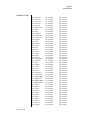
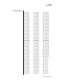
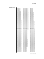
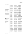
Preset Listing ..............................................................................................310
Pattern Listing ............................................................................................314
Song Listing................................................................................................314
Riff Listing ..................................................................................................315
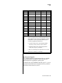
Instrument Notes .......................................................................................317
Flexible Kit Variations ...........................................................................317
Holes .....................................................................................................318
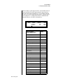
Instrument Listing .....................................................................................319
Example Percussion Maps ..........................................................................325
Arp Map Example ..................................................................................332
Velocity Curves ..........................................................................................333
PatchCord Amount Chart..........................................................................335
Shift Key Shortcuts.....................................................................................336
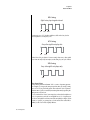
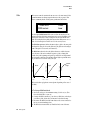
Rhythmic Notation ....................................................................................337
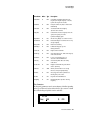
Time Signatures..........................................................................................337
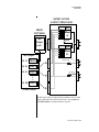
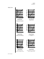
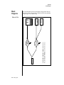
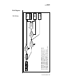
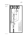
Block Diagrams ..........................................................................................338
Volume & Pan .......................................................................................338
Pads Routing .........................................................................................339
MIDI In .................................................................................................340
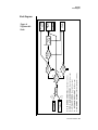
Block Diagrams .....................................................................................341
Triggers & Programmable Knobs ..........................................................341
Quick Edit .............................................................................................342
E-MU Expansion Sound Sets......................................................................343
Installing Sound SIMMs.............................................................................345
MIDI ...........................................................................................................348
Operating System Upgrades ..................................................................353
Received Channel Commands .............................................................355
SysEx Specification ...............................................................................355
Technical Specifications .............................................................................356
Props...........................................................................................................357
Warranty ....................................................................................................358
Index .................................................................................... 361
xii E-MU Systems
Introduction
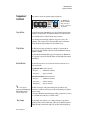
Product
Description
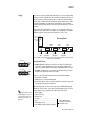
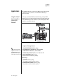
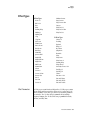
Upgradable Sounds
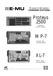
The PX-7 Command Station is a hybrid drum machine featuring a powerful
sequencer and 128-voice synthesizer. The E-MU sound engineers spent six
months meticulously sampling acoustic drum kits in professional studios
around the U.S. to build this diverse collection of drum sounds. These drum
kits have been optimized for the PX-7's advanced synthesis architecture,
with multiple cross-switch layers built into each instrument. PX-7 also
contains three additional, user-upgradable sound SIMM sockets, allowing
you to mix and match sound sets according to your needs. New sounds can
be added as easily as plugging in a new 16MB or 32MB SIMM module.
1024 Presets & more
PX-7 contains 512 user presets and 512 factory ROM presets, but it can be
expanded with literally thousands of ROM presets. (ROM presets are
automatically added when sound SIMMs are installed. As an example, a 32 MB
SIMM may contain up to 1024 ROM presets.) PX-7’s Sound Navigator makes it
easy to find the exact sound you want. It’s powerful, yet simple to use.
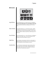
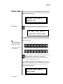
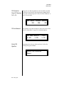
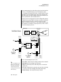
Multi-Function Controllers
Multi-function buttons allow you to trigger sequences, arpeggiators and
loops internally or on any of your other MIDI devices. They can act as Note
Inputs for Grid or Step recording, Track Select, Mute or MIDI Trigger
buttons (latched or unlatched).
Sixteen real-time controller knobs are also multi-function controls. These
knobs make it a snap to edit and modify internal preset parameters.
Another useful mode allows the knobs to control volume and pan for all
sixteen MIDI channels. These controllers are fully programmable and can
control internal preset or other MIDI equipment on multiple MIDI
channels. They can be programmed to adjust multiple internal parameters
at once, allowing complex levels of control. For example, a single knob can
simultaneously turn up filter cutoff, while detuning one sample, and
adjusting the release time of the volume envelope. Virtually every synth
parameter in the PX-7 is controllable using the real-time knobs or by any
internal or external control source.
PX-7 Owners Manual 1
Introduction
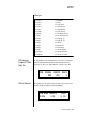
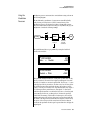
Super Sequencer
PX-7 contains a powerful, yet simple to use 16-track interactive sequencer.
You can record in real-time, step and grid modes and can switch modes
without ever stopping your creative flow. Sixteen dedicated Mute/Select
buttons allow you to add, monitor and modify parts on the fly without
cumbersome menu scrolling. It’s never been this easy to lay down your
ideas. The PX-7 Command Station can store over 300,000 notes and you
can import and export standard MIDI files (SMF) to and from your Mac or
PC using E-MU’s E-Loader program.
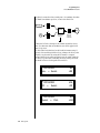
Multi-Channel Arpeggiators
PX-7’s Rhythmic Pattern Generator/Arpeggiator can play up to 32 synchronized arpeggiator patterns at once using a different sound for each! Arpeggiators are yet another way to create unique and unusual drum patterns.
Patterns can be edited using pattern flow commands such as: delay for 2
bars, play for 4 bars, hold for 2 beats and repeat. You can program or
download 100 user patterns in addition to the 200 factory patterns.
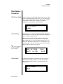
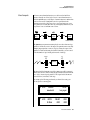
Ultra Powerful Synthesizer
The extremely flexible yet easy to use 4-layer synthesizer voices make it
easy to build sounds of any kind. Layers can be switched or crossfaded
using key position, velocity, real-time controllers or any modulation source.
128 voice polyphony ensures that you can play and sequence the most
complex material. PX-7 also contains 50 different 2nd to 12th order
resonant & modeling filters.
Sixty four modulation sources include three multistage envelopes and two
LFOs per layer, as well as full MIDI control over virtually every parameter.
The digital patch bay, with 24 cords per layer, (and 12 more cords per
preset) lets you connect modulation sources to 64 destinations in any
imaginable way. Synth parameters as well as arpeggiator and BEAT tempos
can be controlled from PX-7 internal clock (or an external MIDI clock). Up
to 8 LFOs and 12 envelopes can be perfectly synchronized at different rates.
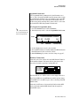
24-bit Effects
Once you have created your preset, you can add richness to your sound
using PX-7’s 24-bit stereo effects. You can choose a different effects setup
for each preset from over 60 algorithms. PX-7’s effects section is actually
two separate effects processors with control over each wet/dry mix level on
four effects sends. Effects Processor “A” contains primarily ambiance
algorithms like reverb and delays, while effects processor “B” contains
primarily spectral algorithms such as chorus, flange, phase, distortion, and
delay. Effects can be linked to each preset or used globally to further
enhance your sound.
Other features include multiple solo, voice assignment and performance
modes for expressive control, 12 user-definable alternate tunings, and, of
course, an extensive MIDI implementation.
2 E-MU Systems
Important Safety Instructions
Important Safety Instructions
Use in countries other than the U.S.A. may require the use of a different
line cord or attachment plug, or both. Refer all servicing to qualified service
personnel. There are no user serviceable parts or adjustments inside the
unit. There are no user serviceable parts inside the power supply enclosure.
WARNING: To reduce the risk of fire or electric shock, do not expose this
product to rain or moisture.
Grounding
Instructions
Mains Switch
Danger!
This product must be grounded. If it should malfunction or break down,
grounding provides a path of least resistance for electric current, reducing
the risk of electric shock. This product is equipped with a cord having an
equipment-grounding conductor and a grounding plug. The plug must be
plugged into an appropriate outlet properly installed and grounded in
accordance with all local codes and ordinances.
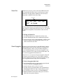
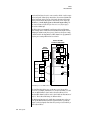
The front panel On/Off switch is a “Soft” power switch that can be used to
turn power on and off when the PX-7 is rack mounted. Use the AC power
switch on the rear panel if you wish to completely disconnect PX-7 from
the AC mains.
Improper connection of the equipment’s grounding conductor can result in
the risk of electric shock. Check with a qualified electrician or service
personnel if you are in doubt as to whether the product is properly
grounded. Do not modify the plug provided with this product. If it will not
fit the outlet, have a proper outlet installed by a qualified technician.
PX-7 Owners Manual 3
Important Safety Instructions
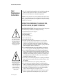
User
Maintenance
Instructions
1.
2.
The PX-7 should be kept clean and dust free. Periodically wipe the unit
with a clean, dry, lint free cloth. Do not use solvents or cleaners.
There are no user lubrication or adjustment requirements.
Caution -Servicing instructions are for use by qualified personnel only. To reduce
the risk of electric shock, do not perform any servicing other than that contained
in these operating instructions unless you are qualified to do so. Refer all servicing
to qualified service personnel.
INSTRUCTIONS PERTAINING TO A RISK OF FIRE,
ELECTRIC SHOCK, OR INJURY TO PERSONS
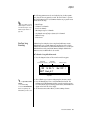
READ THESE INSTRUCTIONS: When using electric products, basic precautions should always be adhered to, including the following:
1.
Read all instructions before using PX-7.
2.
Keep these instructions.
Heed all warnings.
Follow these instructions.
Do not use near water.
Clean only with a dry cloth.
Install in accordance with E-MU’s instructions. Do not block any
openings. This apparatus should be situated so that its location or
position does not interfere with proper ventilation. The ventilation
should not be impeded by covering the ventilation openings with items
such as newspapers, tablecloths, curtains, etc.
Do not install near any heat sources such as radiators, heat registers,
stoves, or other apparatus (including amplifiers) which produce heat.
Do not defeat the safety purpose of the polarized or grounding-type
plug. A polarized plug has two blades with one wider than the other. A
grounding-type plug has two blades and a third grounding prong. The
wide blade or the grounding prong are provided for your safety. If the
provided plug does not fit into your outlet, consult an electrician for
replacement of the obsolete outlet.
Protect the power cord from being walked on or pinched, particularly at
plugs, convenience receptacles, and at the point where they exit from
the apparatus.
Use only attachments/accessories specified by E-MU Systems.
Use only with the cart, stand, tripod, bracket, or table specified by
E-MU or sold with the apparatus. When a cart is used, use caution when
moving the cart/apparatus combination to avoid injury from tip-over.
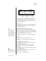
Unplug the PX-7 apparatus from the power outlet during lightning
storms or when left unused for a long period of time.
Refer all servicing to qualified service personnel. Servicing is required
when the apparatus has been damaged in any way, such as power
3.
4.
5.
This symbol is intended to
alert you to the presence of
important operating and
maintenance (servicing)
instructions in the literature
accompanying the unit.
6.
7.
8.
9.
10.
This symbol is intended to
alert you to the presence of
uninsulated dangerous
voltage within the product’s
enclosure that may be of
sufficient magnitude to
constitute a risk of electric
shock to persons.
11.
12.
13.
14.
4 E-MU Systems
Important Safety Instructions
15.
16.
17.
This symbol is intended to
alert you to use caution when
moving a cart/apparatus
combination to avoid injury.
18.
19.
20.
Radio and
Television
Interference
supply cord or plug is damaged, liquid has been spilled or objects have
fallen into the apparatus, the apparatus has been exposed to rain or
moisture, the apparatus does not operate normally or has been
dropped.
No open flame sources, such as lit candles, should be placed on the
apparatus.
The apparatus is designed for use in moderate climates.
The apparatus shall not be exposed to dripping or splashing. No objects
filled with liquids, such as vases, shall be placed on the apparatus.
To reduce the risk of injury, close supervision is necessary when using
the apparatus near children.
The apparatus should be connected only to a power supply of the type
described in the operating instructions and marked on the product.
This product, in combination with an amplifier and headphones and
speakers, may be capable of producing sound levels that could cause
permanent hearing loss. Do not operate for a long period of time at a
high volume level or at a level that is uncomfortable. If you experience
any hearing loss or ringing in the ears, consult an audiologist.
The equipment described in this manual generates and uses radiofrequency energy. If it is not installed and used properly —that is, in strict
accordance with our instructions— it may cause interference with radio
and television reception.
This equipment has been tested and complies with the limits for a Class B
computing device in accordance with the specifications in Subpart J of Part
15 of the FCC rules. These rules are designed to provide reasonable
protection against such interference in a residential installation. However,
there is no guarantee that the interference will not occur in a particular
installation, especially if a “rabbit ear” TV antenna is used.
If PX-7 does cause interference to radio or television reception, you can try
to correct the interference by using one or more of the following measures:
•
•
•
•
Turn the television or radio antenna until the interference stops.
Move PX-7 to one side or the other of the television or radio.
Move PX-7 farther away from the television or radio.
Plug PX-7 into an outlet on a different circuit than the television or
radio.
• Consider installing a rooftop antenna with a coaxial lead-in between the
antenna and television set.
PX-7 Owners Manual 5
Foreign Language Warnings - German
Foreign Language Warnings
- German
Wichtige
Sicherheitsvorschriften
Erdungsinstruktionen
Gefahr
Vorsicht
6 E-MU Systems
In Ländern ausserhalb den U.S.A. können andere Kabel oder Stecker
notwendig werden. Zur Verminderung des Risikos von Feuer oder eines
elektrischen Schlages übergebe man den Service an qualifizierte Fachleute.
Das Gerät niemals Regen oder Nässe aussetzen.
Das Gerät muss geerdet sein. Bei einem Defekt oder Ausfall bietet Erdung
dem elektrischen Strom den Weg des geringsten Widerstandes und
reduziert das Risiko eines Schlages. Dieses Gerät ist mit einem geerdeten
Kabel und Stecker ausgerüstet. Der Stecker muss in eine passende,
einwandfrei montierte und geerdete Steckdose in Übereinstimmung mit
den örtlichen Vorschriften eingeführt werden.
Unvorschriftsgemässer Anschluss des Gerätes kann zum Risiko eines
elektrischen Schlages führen. Im Zweifelsfalle über die ordnungsgemässe
Erdung soll ein qualifizierter Elektriker oder eine Serviecestelle beigezogen
werden. Ändern Sie den mitgelieferten Stecker nicht. Sollte er nicht in die
Steckdose passen, soll die einwandfreie Installation durch einen qualifizierten Techniker erfolgen.
Wird der PX-7 in einem Rackgestell montiert, muss ein offener
19-Zollrahmen verwendet werden.
Foreign Language Warnings - German
Unterhaltsinstruktionen
für anwender
1.
2.
3.
Vorsicht
PX-7 soll sauber und staubfrei gehalten werden. Das Gerät mit einem
sauberen und säurefreien Tuch periodisch abreiben. Keine Lösungsoder Reinigungsmittel anwenden.
Schmieren und Justieren sind nicht notwendig.
Bei weiteren Servicefragen wende man sich an eine qualifizierte Servicestelle.
Diese Gebrauchsanweisungen sind nur für qualifizierte Techniker
beabsichtigt. Um die Gefahr eines elektrischen Schlages zu vermeiden,
sollen Sie keine Arbeit unternehmen, die nicht in diesen Instruktionen
vorgeschrieben ist. Wenden Sie Sich bei weiteren Servicefragen an eine
qualifizierte Servicestelle.
INSTRUKTIONEN BETR. FEUERRISIKO,
ELEKTROSCHOCK ODER VERLETZUNG VON
PERSONEN
WARNUNG; Beim Einsatz elektrischer Geräte sollten
folgende Vorsichtsmassregeln stets beachtet werden:
1.
Dieses Symbol weist den
Anwender auf wichtige
Gebrauchs- und ServiceVorschriften in den beiliegenden Drucksachen.
2.
3.
4.
5.
6.
7.
Dieses Symbol verweist auf
nicht-isolierte Stromspannungen im Geräte-Innern,
welche zu einem elektrischen
Schlag führen könnten.
8.
Lesen Sie vor dem Einschalten des alle Instruktionen.
Zur Vermeidung von Verletzungsrisiken müssen Kinder bei eingeschaltetem PX-7 sorgfältig überwacht werden.
PX-7 nicht in der Nähe von Wasser in Betrieb nehmen -- z.B. in der
Nähe von Badewannen, Waschschüsseln, auf nassen Gestellen oder am
Swimmingpool.
PX-7 stets so aufstellen, dass seine Belüftung nicht beeinträchtigt wird.
PX-7 nicht in der Nähe von Hitze aufstellen, wie Heizkörper, offenem
Feuer, Öfen oder von Backöfen.
PX-7 ausschliesslich mit einem Netzgerät gemäss Bedienungsanleitung
und Gerätemarkierung verwenden.
Dieses Gerät kann bei Verwendung von Kopfhörern und Verstärkern
hohe Lautpegel erzeugen, welche zu bleibenden Gehörschäden führen.
Arbeiten Sie nicht während längerer Zeit mit voller Lautstärke oder
hohem Lautpegel. Stellen Sie Gehörverlust oder Ohrenläuten fest,
wenden Sie sich an einen Ohrenartz.
PX-7 kann mit einem polarisierten Kabelstecker (mit ungleichen
Stiften) ausgerüstet sein. Das geschieht für Ihre Sicherheit. Können Sie
den Stecker nicht in die Steckdose einführen, ändern Sie nicht den
Stecker ab, sondern wenden Sie sich an einen Elektriker.
PX-7 Owners Manual 7
Foreign Language Warnings - German
9.
10.
11.
12.
Das Netzkabel des PX-7 bei längerem Nichtgebrauch aus der Steckdose
ziehen.
Vermeiden Sie sorgfältig das Eindringen von Gegenständen oder
Flüssigkeiten durch die Gehäuseöffnungen.
Das Gerät soll durch qualifizierte Serviceleute gewartet werden, falls:
A. das Netzkabel beschädigt wurde, oder
B. Gegenstände oder Flüssigkeit in das Gerät gelangten,
C. das Gerät Regen ausgesetzt war, oder
D. das Gerät nicht normal oder einwandfrei arbeitet, oder
E. das Gerät stürzte oder sein Gehäuse beschädigt wurde.
Servicearbeiten sollten nur qualifizierten Fachleuten anvertraut werden.
DIESE INSTRUKTIONEN AUFBEWAHREN
8 E-MU Systems
Foreign Language Warnings - French
Foreign Language Warnings French
Instructions
de Sécurité
Importantes
Instructions
de Mise à la
Terre
Danger
Attention
Instructions
de
Maintenance
Une utilisation dans des pays autres que les U.S.A. peut nécessiter l’usage
d’un cordon d’alimentation différent. Afin de réduire les risques d’incendie
ou d’électrocution, référez-vous à un personnel de service qualifié, et
n’exposez pas cet appareil à la pluie ou à l’humidité.
Cet appareil doit être relié à la terre. Dans le cas d’une malfonction
éventuelle, la terre fournit un passage de moindre résistance pour le
courant électrique, réduisant ainsi les risques d’électrocution. Le PX-7 est
équipé d’un cordon muni d’un conducteur et d’une fiche devant être
branchée dans une prise appropriée et reliée à la terre en conformité avec
les normes locales.
Une connexion incorrecte peut résulter en des risques d’électrocution.
Vérifiez avec un technicien qualifié si vous avez des doutes quant à la
connexion. Ne modifiez pas vous-même le cordon d’alimentation livré avec
cet appareil; s’il ne rentre pas dans la prise, faites-en installer un autre par
un technicien qualifié.
Si le PX-7 est installé dans un rack, utilisez un rack standard ouvert de
48.25cm.
1.
2.
3.
Le PX-7 doit être maintenu propre et sans poussière. Nettoyez-le
périodiquement à l’aide d’un chiffon propre et non-pelucheux.
N’utilisez pas de solvants, ou d’autres produits de nettoyage.
Aucune lubrification et aucun réglage ne sont nécessaires de votre part.
Pour tout autre service, référez-vous à un personnel qualifié.
PX-7 Owners Manual 9
Foreign Language Warnings - French
Instructions Concernant les Risques d’Incendie,
d’Electrocution, ou de Blessures Corporelles.
ATTENTION: Lorsque vous utilisez des appareils électriques,
certaines précautions élémentaires doivent toujours être prises,
incluant les suivantes:
Ces instructions de dépanage sont destinées uniquement aux personnes
qualifiées. Afin d’éviter les risques d’électrocution, n’effectuez que les opérations décrites dans ce manuel, à moins que vous ne soyez qualifiê pour cela.
Faites effectuer toute r’eparation par une personne qualifié.
1.
2.
3.
Ce symbole vous alerte de la
présence d’instructions
importantes d’opération et
de maintenance dans la
notice accompagnant
l’appareil.
4.
5.
6.
7.
8.
Ce symbole vous alerte de
la présence d’un voltage
non-isolé dangereux à
l’intérieur de l’appareil,
pouvant être d’une
magnitude suffisante pour
constituer un risque
d’électrocution.
9.
10.
11.
12.
13.
10 E-MU Systems
Lisez bien toutes les instructions avant d’utiliser le PX-7.
Afin de réduire les risques de blessures, une attention particulière est
nécessaire en la présence d’enfants en bas âge.
N’utilisez pas le PX-7 dans ou près d’endroits humides - par exemple
près d’une baignoire, d’un lavabo, dans les toilettes, dans une cave
humide, sur un bar fréquenté, en présence d’un bull-dog en rut, ou
dans une piscine pleine. Protégez cet appareil de tout liquide,
éclaboussure ou fuite.
Le PX-7 doit être placé de façon à ce que sa position n’interfére pas avec
sa propre ventilation.
Le PX-7 doit être placé loin de sources de chaleur telles que des radiateurs, cheminées, fours, ou groupies en chaleur.
Le PX-7 doit uniquement être connecté à une alimentation du type
décrit dans les instructions d’opération et tel qu’indiqué sur l’appareil.
Une attention particulière doit être observée quant aux objets pouvant
tomber et aux liquides pouvant être versés sur et à l’intérieur de le PX-7.
Le PX-7 peut être équipé d’une fiche secteur polarisée (avec une broche
plus large que l’autre). C’est une mesure de sécurité. Si vous ne pouvez
pas brancher cette fiche dans une prise, ne neutralisez pas cette sécurité.
Contactez plutôt un électricien pour remplacer la prise obsolète.
Evitez de marcher sur le cordon d’alimentation ou de le coincer,
particuliêrement prês des prises de courant, des boitiers ‘electriques dt
du point de sortie de l’appareil.
Le cordon d’alimentation de le PX-7 doit être débranché lorsque ce
dernier n’est pas utilisé pendant une longue période.
Cet appareil, combiné avec un amplificateur, des haut-parleurs, et/ou
un casque, est capable de générer des niveaux sonores pouvant
occasionner une perte de l’ouïe permanente. Ne travaillez pas trop
longtemps à un volume trop élevé ou même inconfortable. Si vous
observez une perte de l’audition ou un bourdonnement dans les
oreilles, consultez un O.R.L.
N’utilisez que les accessoires sp’ecifi’es par E-MU Systems.
Cet appareil doit être examiné par un personnel qualifié lorsque:
A. Le cordon d’alimentation a été endommagé, ou
Foreign Language Warnings - French
14.
B. Des objets sont tombés, ou du liquide a été versé sur/à l’intérieur
de l’appareil, ou
C. Le PX-7 a été exposé à la pluie, ou
D. Le PX-7 est tombé, ou
E. Le PX-7 ne fonctionne pas normalement, ou affiche un
changement radical de performance.
Tout service doit être effectué par un personnel qualifié.
SAUVEGARDEZ CES INSTRUCTIONS
Interférences
Radio et
Télévision
L’appareil décrit dans cette notice génére et utilise une énergie de
fréquence-radio. S’il n’est pas installé et utilisé correctement - c’est à dire en
suivant strictement nos instructions - il peut occasionner des interférences
avec la réception d’une radio ou d’une télévision.
Cet appareil a été testé et est conforme aux normes de Classe A en accord
avec les spécifications du paragraphe J de la section 15 des lois FCC. Ces lois
sont désignées pour fournir une protection raisonnable contre de telles
interférences dans une installation résidentielle. Toutefois, il n’est pas
garanti qu’aucune interférence n’apparaisse dans des installations
particulières, et plus spécialement lorsqu’une antenne de télévision en
«oreilles de lapin» est utilisée.
Si le PX-7 occasionne des interférences , vous pouvez essayer de les corriger
en utilisant une ou plusieurs des mesures suivantes:
• Tournez l’antenne de la télé ou de la radio jusqu’à ce que les interférences disparaissent.
• Déplacez le PX-7 d’un côté ou de l’autre de la télé ou de la radio.
• Eloignez le PX-7 de la télé ou de la radio.
• Branchez le PX-7 sur une prise différente que la télé ou la radio.
• Installez une antenne sur le toit munie d’une connexion coaxiale entre
elle et le poste de télévision.
PX-7 Owners Manual 11
Foreign Language Warnings - French
Declaration of Conformity
Manufacturer:
E-MU Systems
1600 Green Hills Road
Scotts Valley, CA 95067-0015 USA
We hereby declare that the equipment listed herein conforms to the
harmonized standards of the following European Commission Directives:
89/336/EEC and 72/23/EEC.
Trade Name:
PX-7
Model Number:
7740
Under 89/336/EEC as amended by 92/31/EEC, and 93/68/EEC
In accordance with EN 55103-1:1996, Emission Environments E4
In accordance with EN 55103-2:1996, Immunity Environments E4
Test information is contained in a report by Atlas Compliance and
Engineering, Inc.
Dated July 5, 2001
Report No.: 0126EMUx17_103
Under 73/23/EEC as amended by 93/68/EEC
In accordance with EN 60950 with amendments A1, A2, A3, A4, A11
This Declaration is made July 5, 2001
12 E-MU Systems
Setup
This section thoroughly describes how to set up your new PX-7 for use.
Setup includes unpacking instructions, how to hook up the unit to your
sound system and, most importantly, how to turn the thing on and off.
Unpacking
Carefully remove PX-7 from the packaging material. Take care to save the
packing materials in case you need to transport the unit. Check to make
sure all components are included and in good condition. If there are
missing or damaged components, contact E-MU Systems immediately for
replacement or repair.
The PX-7 box should include the following components:
•
•
•
•
PX-7 unit
Power cable
This operation manual
Command Station CD-ROM
PX-7 Owners Manual 13
Setup
Basic Setup
Connection
Instructions
MIDI Sound Module
SAM PLE
I
TRANSPOSE
M ASTER/GLOBAL
SAM PLE M ANAGEMENT
MULTIMO DE
PRESET M ANAGEMENT
PRESET DEFINITION
The Headphone
Output is located
on the Front Panel
TRIGGERS
DIGITAL PROCESSING
INC/YES
ABC
1
O
DEC/NO
PRESET
DYNAM IC PROCESING
ENTER
VOLUME
GHI
LOAD
SAVE
AUDITION
TRIGGER MO DE
ESCAPE
3
M NO
5
6
WX Y
8
9
QZ
0
Basic Setup
DEF
2
TUV
7
DRIVE SELE
CT
JKL
4
PRS
M IDI
MIDI In
Power
Switch
110V/220V
50-60 Hz
(auto-select)
Main Outs to Mixer In
TO REDUCE THE RISK OF FIRE OR ELECTRICAL SHOCK,
DO NOT EXPOSE THIS PRODUCT TO RAIN OR MOISTURE.
USB for
E-Loader
Footswitch
Footswitch
Mixer
Amp
Speakers
Power Switch & AC Receptacle
The AC power switch located on the rear panel is a “hard” power switch.
The front panel On/Off switch is a “soft” power switch that can be used to
turn power on and off when the PX-7 is rack mounted. There is no 110/220
Volt power selector switch since PX-7 utilizes an auto-switching power
supply which accepts from 100V-250V, 50-60Hz.
The Right Main output
jack carries a mono mix of the
left and right channels when the
Left Main plug is not plugged in.
The Left Main output jack is a
stereo jack carrying both
channels when the right output
jack is empty.
14 E-MU Systems
Outputs
In order to reproduce PX-7’s wide dynamic range and frequency response,
use a high quality amplification and speaker system and a stereo setup is
highly desirable The headphone output is the same as the Main output
signal. The headphone jack is located on the left side of the front panel.
Footswitches 1 & 2
Connect one or more momentary footswitches for additional control. PX-7
auto-senses either normally-open or normally-closed switches when they
are plugged in. Their functions are programmable in the Controllers,
Footswitch menu and the Preset Edit, PatchCord menu.
Setup
Studio Setup
Studio Setup
MIDI Controller
(MIDI Keyboard, etc.)
R E A L
T IM E
C O N T R O L LE R S
A S S IG N A B L E
K E Y S
P R E S E T
L E V E L
E X IT
EN T E R
S A M P L E
P A G E
S EQ U E N C E R
P R E S E T S EL E C T
1
2
3
4
5
6
7
R E TU R N
8
9
0
.
Computer
EMULATOR
MIDI In
Additional
MIDI
Devices
MIDI Out
MIDI In
In
MIDI
Interface
Out
In
channels
1B-16B
S/PDIF = Main Outs
channels
1A-16A
Out
In
Footswitches
Mixer
Digital Audio Device
Amp
MIDI In
In this setup, PX-7 is controlled by MIDI messages received at the MIDI
input, which are routed by a computer MIDI interface. Any MIDI
controller, such as a MIDI keyboard or a computer, can control the module.
_
Use the main MIDI A
port for OS Downloads & SysEx
dumps.
MIDI Out
PX-7 contains two MIDI output ports (A & B) so that it can transmit on 32
MIDI channels instead of the usual 16.
Audio Outputs
Three sets of programmable stereo outputs (Main, Sub 1, and Sub 2) are
provided. The internal effects are available only on the Main outputs.
Specific presets (or MIDI channels) can be routed to one of these stereo
pairs in order to be processed further or mixed separately. The S/PDIF
output duplicates the function of the main outputs.
Footswitches 1 & 2
The two footswitch inputs accept either normally-open or normally-closed
momentary footswitches and are programmable in the Controllers,
Footswitch menu and the Preset Edit, PatchCord menu.
PX-7 Owners Manual 15
Setup
Performance Setup
Performance Setup
MIDI Controller
(MIDI Keyboard, Sequencer)
R E A L
T IM E
C O N T R O L LE R S
A S S IG N A B L E
K E Y S
P R E S E T
L E V E L
E X IT
EN T E R
S A M P L E
P A G E
Additional
MIDI
Devices
S EQ U E N C E R
P R E S E T S EL E C T
1
2
3
4
5
6
7
R E TU R N
8
9
0
.
EMULATOR
MIDI In
Effect Device
Main Outs to Mixer In
Send/Return
Send
MIDI Out
Digital Effect
S/PDIF In
Analog Out
Sub Output
Return
(To Main Output)
Tip
To Effect
Ring
From Effect
SEND/RETURN CABLE
Signal is sent out on tip of plug and
returned to main outputs via ring of plug.
MIDI In
In this setup, PX-7 is additionally controlled by a MIDI keyboard.
Audio Outputs
The Sub 1 and Sub 2 output jacks are stereo jacks. The tip of each jack
(accessed when a standard phone plug is inserted) connects to the left or
right output of that group. The S/PDIF output is a digital copy of the stereo
signal on the main outputs.
If you insert a stereo plug into one of the Sub Outputs, the ring of the plug
serves as a signal Return which sums into the Main outputs.
Therefore, the Sub 1 and Sub 2 jacks can serve as effect sends and
returns in order to further process selected instruments and then
return them to the main mix.
You can use the Sub 1 and Sub 2 jacks as send/returns in order to further
process selected PX-7 presets without using the effects bus on the mixing
16 E-MU Systems
Setup
Power Down Sequence
board. In a pinch, the effect returns can be used to sum additional instruments into the main outputs. It’s like having an extra line mixer when you
need more inputs!
Output Section
Effects
Processors
L Bus
R Bus
Tip
Tip
Tip
Tip
Ring
Ring
Ring
Ring
R
L
R
L
SUB 2
R
SUB 1
L
MAINS
You can use the Sub 1 and Sub 2 jacks as effect returns to the Main Outputs.
Note that the Effects Processors are only routed to the Main Outputs.
Power Down
Sequence
To avoid accidentally turning off the power while playing PX-7, the front
panel power switch incorporates a five second “fail-safe” feature when
powering down. Once the power down sequence has begun, you have five
seconds to press the power switch again and stop PX-7 from turning off.
POWERING DOWN : 4
Press On / Off to Abort . . .
****
Rack Mounting PX-7
PX-7 can be rack mounted if you so desire. You’ll need (6) rack spaces to fit
PX-7 into your rack. The black end caps remove easily with three screws to
reduce the width to 19 inches. Rack mounting ears are available from your
E-MU dealer (Model 7770).
PX-7 Owners Manual 17
Setup
Rack Mounting PX-7
18 E-MU Systems
Instant Gratification
This section presents step-by-step instructions for the most fundamental
operations to get you up and running as quickly as possible.
Playing Patterns &
Songs
PX-7 on, it comes up in Pattern mode. PX-7 comes with over a hundred
factory patterns. The Pattern screen is shown below.
T 01
STOP Ln:08
000 Ambideep
Bar:01 .1
0
1.
2.
To Play Patterns
Select a pattern using the data entry control.
Press the Play button, located near the center of the unit. The pattern
begins playing and the lower line of the display changes.
T 01
STOP Ln:08 Bar:01 .1
CurPat: 0020 NextPat: 0020
3.
While the pattern is playing, select another pattern using the data
entry control. The name of the pattern to be played next is now shown.
Notice that the Home/Enter LED is now flashing.
T 01
STOP Ln:08
0150 Club Luv
4.
Bar:01 .1
Press the Home/Enter button to select the new pattern. The lower line
of the display now shows the numbers of the Current and Next
PX-7 Owners Manual 19
Instant Gratification
Playing Patterns & Songs
patterns. The new pattern will begin playing when the current pattern
has finished.
T
01 STOP Ln:08 Bar:01 .1
CurPat: 0020 NextPat: 0220
5.
O
PX-7’s buttons have
been designed so that you can
slide your fingers across them to
quickly mute and unmute tracks.
Select a new pattern, press Stop, then press Play to change patterns
without waiting for the current pattern to end.
Track Muting
6. Press the Track Enable/Mute buttons to bring tracks in and out. Every
factory pattern has from eight to sixteen tracks. The LED in each button
illuminates when a track is enabled (unmuted). The diagram below
shows the default factory track assignments.
Track Mixing
7. Press the Mix button (located beneath the LCD) while a pattern is
playing. The Channel Volume display screen appears, showing the
volumes of all 32 channels.
CH VOLS
01A:125
8.
9.
Now press the Controller Function Select button (located above the
controller knobs) twice so that Volume is selected.
The sixteen controller knobs now function as volume controls for MIDI
channels 01A-16A.
• While we’re on the subject of Tracks and Channels, it might be a good
time to mention that in all the factory patterns, a given track will control
the MIDI channel of the same number. That means Track 1 will play the
preset on channel 01A, track 2 will play channel 02A and so on up to 16.
Feel free to turn the knobs and remix the pattern. The LEDs next to the
knobs flash to indicate activity on that channel/track.
Change the Sound
10. Adjust your remix so that track (the bass) is the most prominent
instrument in the mix.
11. Press the Preset View button and select Track using the Track/Channel
buttons to the left of the LCD.
12.
13.
20 E-MU Systems
Now repeatedly press the Controller Function Select button until
“Quick Edit” is selected.
Now the knobs control the bass sound. You know what to do.
Instant Gratification
Playing Songs
O
If you move the cursor
underneath the Preset Name
before changing the preset,
another bass preset will be
selected.
Turn the data entry control to completely change the preset.
15. Use the Track/Channel select buttons to change any of the presets. In
PX-7’s default mode, the active on whichever preset is showing in the
preset view screen. They can be set to always play a specific channel in
the Controllers menu (page 134).
• Nothing is made permanent until you save the pattern or preset, so play
around as much as you like.
14.
Jump Back
16. You can jump between Volume mode, Quick Edit mode or Pattern
mode at any time without missing a beat. Select a new pattern, tweak
parameters, change the mix, enable or mute tracks.
Playing Songs
O
Press the Pattern Mode
button while a Song is playing to
loop on the current pattern.
Pressing Song Mode continues
playing the song.
Now that you’ve explored Pattern mode a little, check out Song mode. In its
most basic form, a song is just a sequence of patterns chained together one
after another.
1.
2.
3.
To Play a Song
Select Song mode by pressing the Song button located underneath the
LCD. (Stop the sequencer first.)
Select one of the factory programmed songs using the data entry
control.
Press Play. The song begins playing.
PX-7 Owners Manual 21
Instant Gratification
Playing Demo Sequences
Playing Demo
Sequences
PX-7 has several factory demonstration sequences that let you hear what
this incredible machine can do. The actual number of demo sequences
depends on which ROM sounds sets are installed. You can play these demo
sequences by accessing the Demo Sequence page.
DEMO SEQUENCES
TripleXXX
1.
2.
3.
DRUM
To Play a Demo Sequence
Press and hold the Song and Pattern buttons at the same time to enter
the Demo Sequence page. The screen shown above appears.
Select a sequence using the data entry control. The Enter LED will be
flashing.
Press the Enter button to begin playing the selected sequence. The
following screen appears.
PLAYING: TripleXXX
Press ENTER to stop
4.
5.
6.
Auditioning Presets
O
To audition presets with
their programmed effects, switch
to Omni or Poly mode (located
in the MIDI menu). Remember
to switch back to Multi mode
before playing sequences again.
22 E-MU Systems
Press the Enter button again to stop playing the sequence.
When a demo sequence plays to the end, the next demo will automatically begin playing. The screen will display the new demo name.
With the sequence stopped, press any other button to Exit demo
sequence mode.
The front panel audition button allows you to hear any preset in PX-7
without even playing a note! When the Audition button is pressed, the
button’s LED will illuminate and a short “Riff” (programmed as part of the
preset) will play. The Riff is latched on and plays continuously until the
button is pressed again. Presets can be changed while Audition is latched.
The top line of the Preset View display changes to show the MIDI Bank
Select controller values needed to select the preset being auditioned. This is
an extremely handy feature when sequencing.
Instant Gratification
Selecting and Quick Editing Presets
Bank
1030
1.
2.
3.
4.
5.
6.
7.
Selecting and Quick
Editing Presets
MSB:019 LSB:0 DRUM
kit: DanceCommand
To Audition a Preset
Select Preset View mode by pressing the preset button in the Mode/
View section immediately below the LCD.
Select a preset by turning the data entry control while the cursor is
anywhere on the lower line. The preset number field (shown above) is
the normal position of the cursor and pressing the Enter button will
return the cursor to this position.
Press the Audition button on the front panel. The Audition LED will
illuminate and a short riff will play the selected preset.
Continue to select and audition presets.
Press the Audition button again to turn Audition mode off. The LED
will extinguish.
Play the rubber keypads.
Be sure to check out the transposition buttons and touchstrip.
The first thing you’ll do with the PX-7 is select and play the factory
provided presets. PX-7 comes standard with 8 banks containing 128 presets
each. See “Preset Screen” on page 42.
Channel
Number
C01A
1030
Initial
Volume
Setting
Initial
Pan
Setting
Arpeggiator
Setting
Preset
Location
V127 P01R A:off User
kit: DanceCommand
Blinking
Preset
Cursor Number
Bank
Number
Preset
Category
Preset
Name
The first four banks are User locations that can be overwritten and used to
store your own presets. The presets that come stored in the User presets are
duplicated in banks 0-3 of the “DRUM” ROM bank, so feel free to overwrite
them with your own presets. You won’t be losing anything.
PX-7 Owners Manual 23
Instant Gratification
Selecting and Quick Editing Presets
The ROM Card identifier is shown in the top right of the display. The preset
is identified in the bottom line of the main screen (the screen that appears
when you press the Mode/View Preset button).
Each bank of 128 presets is identified by a superscripted Bank Number to the
right of the preset number. The bank numbers reset to 0 at the start of each
ROM card you have installed. So with the DRUM ROM installed, the USER
banks will go from 0-3, then start over from 0-3 for the DRUM ROM banks.
Bank Organization
The User Banks
are duplicated
in the DRUM
ROM bank.
}
USER
USER
USER
USER
Bank 0
Bank 1
Bank 2
Bank 3
128 Presets
128 Presets
128 Presets
128 Presets
DRUM
DRUM
DRUM
DRUM
Bank 0
Bank 1
Bank 2
Bank 3
128 Presets
128 Presets
128 Presets
128 Presets
The four User Banks can hold 512 custom presets. Feel free to overwrite these since the
factory user presets are duplicated in nonvolatile ROM.
To the right of the preset number and bank is the preset Category name
followed by the Preset Name.
1.
2.
O
You can select presets
from the Preset Number, Bank
Number, Preset Category or
Preset Name fields.
3.
4.
Notice that an asterisk
appears in the display when you
change the knobs. This indicates
that you have edited the preset.
24 E-MU Systems
5.
To Change the Preset
Press the Preset button in the Mode/View box directly below the liquid
crystal display. The main Preset selection screen appears.
The cursor will be located under the first character in the Preset Number
field. This is the “Home” position which is selected instantly when you
press the Home/Enter button. Pressing either of the two cursor buttons
repeatedly also gets you there.
Turn the data entry control knob on the front panel to select a new
preset number. If you turn the knob slowly, the presets advance one
number for each “click” of the knob. If you spin the knob quickly, the
numbers advance much faster (more than one number per click).
Play the keyboard (or press the Audition button) and listen to the
sounds made by your PX-7!
TRY OUT ANY OF THE 16 KNOBS on the front panel (in Quick Edit
mode) and note how they change the sound of each preset! Don’t worry
about ruining the sound, the values are automatically reset as soon as
you select a new preset.
Instant Gratification
Exploring the Master Arpeggiator
Exploring the Master
Arpeggiator
PX-7’s multi-channel Pattern Generator/Arpeggiator is one of the greatest
features ever put in a synth. Let’s explore the Master Arpeggiator.
1.
2.
3.
To Arpeggiate a Single Preset:
Select a preset. Note that the factory presets all have prefixes which
describe the type of sound. For this investigation it might be best to
choose a preset with the prefix “arp,” for arpeggiator. These presets are
optimized for use with the arpeggiator.
Set the Arp parameter in the main preset selection screen to “M” for
Master Arpeggiator.
Press the Arp button in the Edit section of the front panel to access the
master Arpeggiator menu, then use the data entry control to scroll to
the screen shown below.
MASTER ARPEGGIATOR
Status
4.
O
Try using control knobs
15 & 16 to change the
arpeggiator parameters.
5.
6.
on
Make sure the arpeggiator Status is “on.” Play the keyboard to start
arpeggiating.
Press either cursor key repeatedly to move the cursor below the Status
field.
Turn the data entry control clockwise one click. The Mode screen
appears.
MASTER ARPEGGIATOR
Mode
up
7.
8.
9.
10.
Use the cursor keys to move the cursor to the Mode field (up, down, up/
down, forw asgn, backw asgn, forw/backw, random, pattern). Try out
the different modes as you play the keyboard.
Move the cursor back to the lower left position and explore the other
parameters. The Note Value parameter changes the rate of the arpeggios.
By the way, note value is a divisor based on the Master Tempo. Try
changing the tempo, but come right back.
Let’s check out the pattern generator. Go back to the Mode screen and
set the mode to “Pattern”.
Now advance to the Pattern screen (shown below) and move the cursor
to the Pattern Number field (the second field from the left).
PX-7 Owners Manual 25
Instant Gratification
Multi-Channel Arpeggiator
MASTER ARPEGGIATOR
Pattern 380 Inversions
O
Try the various patterns. There are 200 permanent factory patterns and
100 user locations to store the patterns you create. Each pattern can
have up to 32 notes.
See the Arpeggiator
Chapter for detailed information
on creating Patterns.
11.
Multi-Channel
Arpeggiator
PX-7 is totally unique in its ability to run up to 32 arpeggiators at once!
Even two or three patterns at once can create very complex sequences and
dynamic landscapes of sound.
Here’s one way to access this ultra-powerful feature. There is one arpeggiator for each MIDI channel. First you’ll assign three of the Trigger Keys to
MIDI channels 01A-03A. Next, you’ll assign arpeggiator presets to these
channels. Then you’ll become addicted to this new way of making music.
O
Make sure the “Trigger
Buttons Function” in the
Controllers menu is set to “Play
Note Events”.
Program the Trigger Keys
1. Press the Controllers button, then turn the data entry control until the
screen shown below appears.
2. Move the cursor until it is underneath the Latch field and turn Latch
mode On.
3. Move the cursor until it is underneath the Channel field (Ch) and set
the channel to 01A.
4. Move the cursor until it is underneath the Trigger field (T1) and
change the Trigger to T2 (trigger button 2).
5. Turn Latch On for trigger button 2 and set the channel to 02A.
6. Change the Trigger to T3 (trigger button 3).
7.
Turn Latch On for trigger button 3 and set the channel to 03A.
Set up the Presets
8. Press the Preset View button (located beneath the LCD). The preset
select screen appears.
9. Move the cursor underneath the Category field (as shown above) and
select the “arp” category.
10. Move the cursor underneath the preset name and select any “arp”
preset for channel 1A.
11. Press the “+” Track/Channel select button (located to the left of the
LCD), so that C02A is displayed.
12. Select any other “arp” preset for channel 2A.
13. Select channel 03A and choose another arp preset.
26 E-MU Systems
Instant Gratification
Multi-Channel Arpeggiator
Select Trigger Mode
14. Press the Selector Button in the upper left corner of the Command
Functions section. Pressing this button will switch between Track
Enable/Mute and Triggers mode. Select Triggers mode.
O
Sometimes a simple
volume change will bring out
hidden voices and patterns.
Play it!
15. Now press Trigger Buttons 1, 2 and 3. You should be hearing three
arpeggiators playing at once.
16. Change the arp preset on the current MIDI channel. Since the cursor is
located on the preset name, all your selections will be in the arp
category.
17. Press the Track/Channel button and change the arp presets for
channels 1A, 2A & 3A. Since each factory preset has differently
programmed arpeggiator settings, changing the preset not only changes
the sound, but the arpeggiator as well.
18. You can also play the keypads. You’ll be playing the preset currently
showing in the display.
19. Press the Control Select button above the knobs so that “Quick Edit” is
selected. Adjusting the front panel control knobs now modifies the
preset showing on the LCD.
20. Press the Control Select button above the knobs again so that
“Volume” is selected. The first three knobs now control the volume of
each arpeggiator preset.
There’s lots more to the arpeggiators. To find out more, refer to the
arpeggiator chapter beginning on page 243.
Time to Save?
Multisetups save your
entire PX-7 setup. Find out more
on page 146.
If you want to SAVE everything exactly as it is, continue on.
1.
2.
3.
4.
5.
6.
Press the Save/Copy button.
Rotate the data entry control until you get to the menu shown below.
Press the right cursor button to move to the lower line.
Name your Multisetup so you can find it later, then press Enter.
Scroll to the next screen using the data entry control.
Move the cursor to the lower line, select a location and press Enter.
To Record the Trigger Buttons
You can record the note trigger buttons into the sequencer in order to
automate your multi-arpeggiator performance. These instructions also
apply to recording trigger buttons without the arpeggiators.
1.
2.
Set up the multichannel arpeggiators as described on page 26.
Press the Pattern Edit button and scroll to the Channel Assign screen
shown below.
PX-7 Owners Manual 27
Instant Gratification
Multi-Channel Arpeggiator
If you want to record the
Trigger Buttons on a single MIDI
channel, set the track Channel
Assignment to the same channel
as the trigger buttons.
3.
Set the channel setting to MultiA and Dest: internal, as shown in the
screen below. (The trigger buttons are set to play on multiple MIDI channels.
if this track were not set to Multi, all channels would be rechannelized to the
selected channel and the triggers would play back incorrectly.)
T
01 CHANNEL ASSIGN
Channel: MultiA
Dest: int
4.
Make sure that the Trigger Buttons destinations are set to “seq” as
shown below. (This sends the trigger keys to the sequencer input.)
T1 TRIGGERS C3
Latch:on Ch: 01A
5.
6.
7.
8.
28 E-MU Systems
Vel: 127
seq
Set to
seq
Save the Multisetup.
Start with a new blank pattern and set the pattern length. Choose 20
bars or so to start.
Restore the Multisetup. (Just to make sure everything is set up correctly.)
Press Record, then Play. Start recording the trigger buttons.
Basic Operations
Basic Operations
C01A V127 P00 A:P User
0
019 kit:Whack Kit
The PX-7 front panel contains an LCD screen, 49 buttons, and 16 real-time
controller knobs. Functions are grouped logically and the controls are
arranged for ease of use.
Power Switch
The front panel On/Off switch is a “Soft” power switch that can be used to
turn power on and off when the PX-7 is rack mounted. Use the AC power
switch on the rear panel if you wish to completely disconnect PX-7 from
the AC mains.
The power switch incorporates a “fail-safe” feature when powering down.
Once the power down sequence has begun, you have five seconds to press
the power switch again and stop PX-7 from turning off.
Volume Control
This control is the master volume control for all audio outputs. The Volume
Control does not affect any editing or user interface operations. The front
panel volume control is a digital attenuator. For maximum dynamic range,
turn this knob all the way up and control the volume from your mixer or
amplifier.
12VDC Lamp
The BNC connector in the upper left corner of the PX-7 panel supplies 12
volts DC at 250 mA to power a standard mixing desk lamp. (Order E-MU
Model Number 7773 - Locking Lamp from your E-MU dealer.)
PX-7 Owners Manual 29
Basic Operations
Mode/View Buttons
Mode/View
Buttons
The Song and Pattern buttons change both the mode and current display
view. Pressing Song or Pattern places the PX-7 in the selected mode.
Since Song and pattern are Mode buttons, the LEDs stay on when they have
been selected, even if Preset or Mix view buttons are activated.
An asterisk (*) appears in
the Pattern, Song or Preset
display to indicate that the item
needs to be saved.
Song Mode
Display
:100 M:04/4
Bar:001.1
000 256 bar blank
Pattern Mode
Display
T 01
STOP Ln:01 Bar: 01.1
009 1 Smooth 6
The Preset button brings up the Preset/MIDI Channel selection screen
shown below. This important screen allows you to change the Preset,
Volume and Pan position for all 32 MIDI channels. The Preset button does
not change the Song or Pattern mode status and this screen can be edited
while a Pattern or Song is playing back.
Preset Select
Screen
C01
079 3
V127
P01 R
A:off
User
bts: Logic
The Mix button brings up a graphic display of the volume settings for all 32
MIDI channels. This is the same volume setting as in the Preset Select
screen except that all 32 MIDI channels can be simultaneously viewed and
edited. The Mix button does not change the Song or Pattern mode status
and this screen can be edited while a Pattern or Song is playing back.
Mix Screen
1.
30 E-MU Systems
CH VOLS
01A:125
To View the Pan Settings for all 32 Channels
Press the Home/Enter key (to move the cursor to “Home” position) and
turn the data entry control clockwise from the Mix screen.
Basic Operations
LED View Select Section
Track/Channel +/Buttons
These very handy buttons, located to the left of the LCD, serve as a shortcut
to increment or decrement the Track (in Pattern mode), the MIDI Channel
(in Preset mode), Layer (in Preset Edit mode) or Step Numbers (in Arpeggiator Edit mode).
Pressing the increment track button from 16 will wrap around to 1, and
pressing the decrement key from 1 will wrap back to 16. Channel selection
works in the same way.
Data Entry Control
The data entry control is a stepped, variable control switch used to change
parameter values. The wheel increments or decrements the current value
one unit with each click. This control incorporates acceleration, which
advances the value faster if the data entry control is turned quickly.
Left/Right Cursor
Buttons
These buttons move the cursor to the next parameter on the display. (The
cursor is a little flashing line underneath one of the parameters in the
display.) Press either cursor button until the cursor is underneath the
desired parameter. The cursor buttons have an auto-repeat feature which
advances the cursor when the button is held continuously.
The cursor can be moved bidirectionally using the data entry control while
either cursor select button is held down (for example, press and hold the
right cursor button and turn the data entry control).
LED View
Select Section
O
Selecting patterns using
this method allows you to see
the current and next pattern
numbers.
The numeric LED display in the center of the PX-7 can display: Tempo,
Pattern Number, the current Bar/Beat, or the MIDI Channel. Repeatedly
pressing the Select button cycles through the four modes.
Pressing the Edit button lights its associated LED and allows you to edit the
displayed value using the data entry control. Pressing Edit again deactivates
this mode. To select a new pattern, you must exit Edit mode for the new
pattern to be selected.
By pressing and holding the Edit button, and then turning the data entry
control, the displayed parameter can be quickly edited without latching the
Edit mode on.
PX-7 Owners Manual 31
Basic Operations
Sequencer Controls
Sequencer
Controls
Stop Button
These buttons control the sequencer transport functions.
The Tap-Tempo key
functions as a Shift
Key to access other
features. See pages 62,
125, and 140.
Pressing the Stop button immediately stops any currently playing Pattern
Sequence or Song Sequence. The sequence remains at its current location.
Press the Play button to resume from the current location.
Press the Stop button when the sequence is stopped to return to the
beginning of the sequence (RTZ). Pressing the Stop button a third time
reloads the initial setup information for the Pattern or Song.
Play Button
The Play button engages the transport, regardless of sequencer mode
(except in step edit). The LED in the button will be illuminated when the
sequence is running.
Pressing Play while in Record mode puts the sequencer into Pause mode.
The sequencer stops and the Play LED flashes. Pressing Play again resumes
Record mode.
Record Button
The Record button selects one of the three Pattern record modes or two
Song record modes.
Song Record modes (from Song mode)
• One press .............. Realtime record mode
• Two presses ........... Step record mode
Pattern Record modes (from Pattern mode)
• One press .............. Realtime record mode
• Two presses ........... Grid record mode
• Three presses ........ Step record mode
O
While a pattern is
playing, press and hold the Play
button and press Record to
jump into Grid Edit mode.
Tap Tempo
32 E-MU Systems
The LEDs to the right of the button indicate the record mode. After
selecting a record mode, the Play button LED will be flashing. Press Play to
begin recording.
You can press Record at any time during recording or playback to go in and
out of Realtime Record mode (i.e. Punch In & Out)
The Tap Tempo button allows you to change the tempo at any time by
tapping the button at the desired tempo. Three taps are initially required to
change the tempo and then the tempo follows with each subsequent tap.
Basic Operations
Edit Section
Edit Section
Song Edit Button
The Song Edit menu allows you to name and edit songs. An illuminated
LED in the button indicates that you are in Song Edit mode. For more information about Songs and Song mode, see page 103. When pressed in combination with the Pattern Edit button, Song Edit puts the PX-7 in Demo
mode.
Pattern Edit Button
The Pattern Edit menu allows you to name and edit patterns. An illuminated LED in the button indicates that you are in Pattern Edit mode. For
more information about Patterns and Pattern Editing, see page 52. When
pressed in combination with the Song Edit button, this button puts PX-7 in
Demo mode.
Preset Edit Button
The Preset Edit menu allows you to create and edit presets. An illuminated
LED in the button indicates that you are in Preset Edit mode. For more
information about the Preset Edit menu, see page 199.
Global Button
The Global menu contains parameters that affect the entire machine. An
illuminated LED in the button indicates that you are in the Global menu.
For more information about the Global menu, see page 145
Controllers Button
The Controllers menu contains parameters that are related to the front
panel controller knob and button triggers. An illuminated LED in the
button indicates that you are in the Controllers menu. For more information about the Controllers menu, see page 133.
PX-7 Owners Manual 33
Basic Operations
Edit Section
Arpeggiator Button
The Arpeggiator menu contains parameters that are related to the Master
Arpeggiator such as creating and editing arpeggiator patterns. An illuminated LED in the button indicates that you are in the Arpeggiator menu.
For more information about the Arpeggiator menu, see page 243
MIDI Button
The MIDI menu contains parameters that are MIDI related. An illuminated
LED in the button indicates that you are in the MIDI menu. For more information about the MIDI menu, see page 159.
MIDI Panic Button
Pressing the MIDI and Home/Enter buttons simultaneously sends a MIDI
“All Notes Off” and “All Sound Off” for all 32 MIDI channels.
Home/Enter Button
The Home/Enter button is dual purpose. In general, this button acts as the
“Home” button. For example, when in an Edit menu, this button snaps the
cursor to the page name field of the current screen. When viewing the
Preset Select screen, this button snaps the cursor to the preset number field.
The flashing green LED of the Home/Enter button indicates that pressing
the button will initiate a particular operation.
Save/Copy Button
The Save/Copy button is used to save changes to a pattern, song, preset,
copy data between presets, randomize presets and to move other types of
data. Selected groups of parameters, such as PatchCord settings, can be
copied between Presets and/or between Layers using this menu. The menu
is context-sensitive and will start at the appropriate save screen. See Save/
Copy on page 285 for more information.
The LED in the button illuminates to indicate that you are in the Save/
Copy menu. The LED also illuminates when any preset parameter has been
changed in the Edit menu (or if the front panel knobs have been moved
with Quick-Edit mode enabled).
Compare Button
The Compare button allows you to toggle between an edited version of a
preset and the original, unedited version. When a preset has been edited,
an asterisk appears in the preset name field and the Save/Copy LED flashes.
Press the Compare button, lighting it’s LED, to hear the unedited preset.
Press the Compare button again to hear the edited preset. If edits are made
to the preset while listening to the compared original version, compare
mode is aborted and the compare LED goes off.
Audition Button
When the Audition button is pressed, the LED next to the button will
illuminate and a short “Riff” (programmed as part of the preset) will play.
The Riff is latched on and plays continuously until the button is pressed
again. Presets can be changed while Audition is latched on. See “Bank Select
Commands” on page 196 for more information on selecting banks via MIDI.
34 E-MU Systems
Basic Operations
Real-time Controller Knobs
The top line of the Preset display changes to show the MIDI Bank Select
controller values needed to select the preset being auditioned. This handy
feature lets you know the exact Bank and Preset number.
MSB
Preset #
Real-time
Controller
Knobs
Bank
082 2
LSB
MSB:019 LSB:2
kit: Banger
DRUM
The Real-time Controller Knobs can serve several purposes. The first four
functions are selected using the Controller Function Select button above
the realtime control knobs. Preset Quick Edit can be enabled to use the
knobs for editing in the Preset Edit menu.
1.
2.
3.
4.
Quick Edit - Real-time control of internal synthesizer parameters and
“Quick Editing” the initial settings of the real-time controllers
Programmable Knobs - Real-time control of MIDI continuous
controllers on external synthesizers
Volume - Setting the volume of 16 channels.
Pan - Setting the pan position of 16 channels.
Controller Function Select
PX-7 Owners Manual 35
Basic Operations
Real-time Controller Knobs
Knob Functions
Quick Edit mode
The Real-time controller knobs provide direct control of the PX-7’s synthesizer parameters when the Controller Function Select is set to Quick Edit.
O
Quick Edit knob
movements can be recorded into
the sequencer using realtime
song or pattern record modes.
There is an LED next to each of the control knobs which illuminates to
indicate that the knob setting has been changed from the value
programmed in the preset (“Knobs Preset Quick Edit” mode must be
enabled in the Controllers menu). If the knob position is returned to the
original setting, the LED is extinguished.
Initial controller values can be stored in every preset. When you move a
knob with Quick-Edit enabled, the Initial Controller Value is updated with
the knob’s new value. The knob’s LED lights indicating that the preset value
has been changed. The MIDI A-P values are stored in the corresponding
Initial Controller Amount parameter in the Preset Edit menu (see “Initial
Controller Amount” on page 238). The Save/Copy button LED flashes to
remind you that the preset has been edited. “Quick-Edits” made to a preset
are lost if you select another preset before saving them.
The four rows of knobs always control the preset on the basic MIDI channel
(the channel showing on the preset select screen), when the control switch
is set to Quick Edit.
The labels (Filter Cutoff, Filter Q, Filter Attack, Filter Decay, etc.) printed on
these rows show how the factory ROM presets are programmed to respond.
(The controls may not exactly conform to the front panel labels depending on the
preset.) You can change the way a preset responds to MIDI A-P messages
from the Preset Edit menu (PatchCords). The knobs only generate a
message when you move a knob to a new value. The current value jumps to
the new value.
1.
2.
3.
4.
5.
6.
36 E-MU Systems
To Quick-Edit a Preset
Select Quick Edit mode using the Controller Function Select button.
Use the Control Knobs to change the sound of the current preset as
desired. An asterisk (*) appears in the preset view display indicating that
the preset has been modified.
Press the Save/Copy button. You may have to turn the data entry
control so that the display reads, “Save PRESET to.”
Press the right cursor button to select the bottom row.
Optional: Select a new preset location if you don’t want to overwrite
the current preset, or if the current preset is a ROM preset.
Press the Enter button to save the preset.
Basic Operations
Real-time Controller Knobs
Programmable Knobs mode
If the “Programmable Knobs” parameter in the Controllers menu is set to
“Ext,” or “Both,” the system sends MIDI controller messages when you turn
the Controller knobs. Each knob can be programmed to send on any MIDI
channel (01A-16B) and on any continuous controller number from 1-95.
The knobs only generate a message when you move a knob to a new value.
The Controller Knob LEDs always remain off in this mode.
O
Turning a knob while in
this screen automatically selects
that knob for programming!
1.
2.
To Program the Programmable Knobs
Press the Controllers button. Its LED will illuminate.
Turn the data entry control to select the Programmable Knobs screen.
Knob #
K1 PROGRAMMABLE KNOBS
Ctrl: 22
Ch:01A
Ext
CC#
3.
4.
5.
MIDI Chan
Int/Ext/Both/Seq
Use the left/right cursor controls to select the fields.
Select the MIDI Continuous Controller number, the MIDI channel, and
Internal/External or Both for each of the 16 knobs.
Save the Multisetup if you want to save these settings. See page 147.
Multichannel Volume Knobs
In this mode, each of the 16 knobs will control MIDI Channel Volume for
the like-numbered channel. This directly edits the value shown on the
preset select screen and is equivalent to sending MIDI cc#7.
CH VOLS
01A:098
View Mode must be set to “MIX” in order to see the display shown above.
When “Knobs MIDI Out” in the MIDI menu is enabled, any knob change
will send MIDI cc#7 to the MIDI out port as well as controlling the internal
channel volume.
In this mode, the LEDs next to the sixteen knobs blink to indicate MIDI
activity on the same numbered MIDI channel (from the sequencer or
external MIDI sources).
PX-7 Owners Manual 37
Basic Operations
Real-time Controller Knobs
Multichannel Pan Knobs
In this mode, each of the 16 knobs will control MIDI Channel Pan for the
like-numbered channel.This directly edits the value shown on the preset
select screen and is equivalent to sending MIDI cc#10.
CH PANS
01A:56 R
View Mode must be set to “MIX” in order to see the display shown above.
When “Knobs MIDI Out” in the MIDI menu is enabled, any knob change
will send MIDI cc#10 to the MIDI out port as well as controlling the
internal channel volume.
In this mode, the LEDs next to the sixteen knobs blink to indicate MIDI
activity on the same numbered MIDI channel (from the sequencer or
external MIDI sources).
38 E-MU Systems
Basic Operations
Trigger/Mute Buttons
Trigger/Mute
Buttons
The trigger button section serves multiple purposes which are listed below.
•
•
•
•
Assignable & latchable note triggers. See page 138.
Sequencer track select/mute buttons See page 20 and page 52.
Sequencer grid edit entry keys. See page 63.
Preset Edit menu jump keys. See below.
Mode Switch
O
Trigger button
presses can be recorded into
patterns and songs.
The mode switch is normally used to select between Triggers and Track
Select/Mute. In Sequencer Grid Edit, the mode switch is used to select step
resolution.
Trigger Mode
Select Triggers mode by pressing the mode select button so that the
“Triggers” LED is illuminated. Now the 16 buttons work like keyboard
notes. Each of the 16 buttons can be assigned to any MIDI note, on any
MIDI Channel (01A-16B), with any velocity (0-127), and can be set to be
latched or momentarily on. Latched note will hold until the button is
pressed again. Latched notes will be indicated by the LEDs. Trigger keys are
assigned from the Controllers menu. See page 138 for more information.
Preset Menu
Jump Keys
Whenever you are in the Preset Edit menu, the sixteen command buttons
function as “jump” buttons to the various screens in the Preset Edit menu.
The jump location is labelled directly below each button.
Pressing a jump button instantly takes you to the first screen in the selected
category. Pressing the button again takes you to the second screen in the
category and so on. Repeated pressing will rotate you back to the first
screen in the category.
PX-7 Owners Manual 39
Basic Operations
Touchstrip, Transpose, Keypads & Glide
Touchstrip,
Transpose,
Keypads &
Glide
The Touchstrip is a bi-directional controller which is normally connected to
control pitch. It can, however, be patched in to any modulation destination
in the Cords section of the Preset Edit menu. The Touchstrip is referred to
and programmed as “Pitch Wheel” in the Cords menu. See page 228.
Simply slide your finger along the touchstrip while playing the keypads to
hear pitch bend. There is a slight “dead band” in the very center of the strip
to facilitate starting on pitch. You can press anywhere along the strip and
the pitch will instantly jump to that setting. When you release your finger,
the pitch will jump back to normal.
Touchstrip Hold
The Touchstrip Hold button holds the pitch at the position last touched so
that it doesn’t jump back to center when released. The LED in the button
illuminates when this function is on.
Transpose Buttons
These buttons transpose the current range of the rubber keyboard up and
down in one octave intervals. The LEDs on either side of the transpose
buttons show the currently selected range. With no LEDs illuminated, the
keyboard is in its normal range, Middle C to High C (60-72). Each LED to
the right of the buttons stands for one octave up. Each LED to the left of
the buttons stands for one octave down.
Rubber Keypads
The velocity and pressure-sensitive keypads can play on any MIDI channel
as programmed in the Controllers menu. They are normally set to play on
the “Basic” channel, which means that they play the preset currently
showing in the preset view screen. The keypads output channel (mono)
pressure internally (routed in the PatchCords) and both channel and
polyphonic pressure over MIDI.
Glide Button
This button turns Glide (portamento) on or off for the current preset. The
LED in the button illuminates when Glide is turned on in the current
preset. See Glide on page 218.
40 E-MU Systems
Basic Operations
Touchstrip, Transpose, Keypads & Glide
Erase Button
When this button is latched on (LED illuminated) while recording a
pattern, any note played on the keyboard will remove that note from the
pattern as long as the keyboard key is held down. This allows you to
quickly removed any “flubbed” notes without having to enter Pattern Edit
mode.
In Grid record mode, pressing the Erase button while the cursor is on one of
the grid locations, removes the note from that location.
In Song step record mode, pressing the Erase button erases the currently
selected step from the song.
Repeat Button
_
Using the Repeat button,
even in play mode, causes the
current pattern to be dirtied
(asterisk showing). Although
nothing is actually recorded in
the current pattern, this could
cause an unsaved pattern to be
wiped out.
When this button is latched on (LED illuminated) while recording a
pattern, played notes will repeat at the current pattern quantize setting
(page 53). You can get some great effects with this feature by simultaneously changing the volume or pitch as the sound repeats.
In Song step edit mode, the Repeat button functions as a “Pattern Insert”
button. See page 104 for more information.
PX-7 Owners Manual 41
Basic Operations
Preset Screen
Preset Screen
_
The Preset Select screen is accessed by pressing the Preset View button
located directly under the LCD. This screen allows you to examine or set
the Preset, Volume, Pan Position and select the Preset (sound) for each of
the 32 MIDI channels.
Realtime changes made
to this screen are NOT recorded
as part of your pattern or song.
See page 59 to learn how to
record volume and pan
information into your sequences.
MIDI Channel
Selection
C01A
079 3
1.
2.
V127
P01 R
A:off
User
kit: Hide & Seek
To Change the MIDI Channel
Press the Preset View button to display the Preset Select screen.
Press the Track/Channel buttons located to the left of the liquid crystal
display to select channels 01A through 16B. The preset, volume and
pan settings for each channel will be displayed as you scroll through
the channels.
The channel number shown in the main screen is the Basic MIDI Channel
when in Omni or Poly modes.
Preset Selection
1.
2.
Contents
128 RAM Presets
128 RAM Presets
128 RAM Presets
128 RAM Presets
128 ROM Presets
128 ROM Presets
128 ROM Presets
??
Depending on
ROM sets installed
ROM 1
USER
Bank
0
1
2
3
0
1
2
*
An asterisk in the
preset view screen indicates
that the preset has been
modified.
(Change the preset without
saving to remove the
asterisk.)
42 E-MU Systems
3.
To Change the Preset
Press the Preset View button to display the Preset Select screen.
Press either cursor key until the cursor is underneath the preset
number. (The cursor is a little flashing line underneath one of the
parameters in the display.) As you rotate the data entry control, the
preset number and name changes.
The displayed preset is assigned to the displayed MIDI channel. Presets
are arranged into banks of 128, as shown in the diagram at left.
Bank Number
Preset
Number
C01A
V127
P01 R
079 2
kit: Sympel
A:off
User
*
Indicates that the
preset was modified
Using the screen above as an example, the superscripted number 2 in the
second line of the display identifies the current bank number.
• Select banks independently of the of the preset number by locating the
cursor on the Bank field and turning the data entry control.
Basic Operations
Preset Screen
MIDI BANK SELECT
MSB LSB
cc00 cc32
USER
USER
USER
USER
00
00
00
00
00
01
02
03
Bank 0
Bank 1
Bank 2
Bank 3
DRUM
DRUM
DRUM
DRUM
19
19
19
19
00
01
02
03
Bank 0
Bank 1
Bank 2
Bank 3
This chart shows the MSB and LSB numbers needed to select preset banks over MIDI.
Select a bank, then send the program change number. Without a bank select command,
presets are selected from within the current bank.
Channel Volume
Channel Volume sets the volume of the selected MIDI channel in relation
to the other channels. This is the same parameter as MIDI volume control
#7, and changes made over MIDI are shown in the display.
Volume
1.
2.
3.
C01
V127
P01 R
079 2
kit: Sympel
A:off
User
To Change the Channel Volume
Press the Preset View button to display the Preset Select screen.
Press either cursor key until the cursor is underneath the volume value.
Rotate the data entry control to select a volume level. The Channel
Volume range is 000-127.
PX-7 Owners Manual 43
Basic Operations
Preset Screen
Channel Pan
Channel Pan sets the stereo position of the selected MIDI channel. This
control operates like the balance control on your home stereo system.
Channel Pan is the same parameter as MIDI pan controller #10, and
changes made over MIDI are shown in the display.
Pan Position
C01
079 2
V127
P01 R
A:off
User
kit: Sympel
Note: Pan settings in the preset ADD algebraically with the Channel Pan
setting. Therefore, if the pan setting in the preset were set to “63R,” moving
the Channel Pan setting full left would return the sound to the center
position.
1.
2.
3.
Channel Arpeggiator
To Change the Channel Pan
Press the Preset View button to display the Preset Select screen.
Press either cursor key until the cursor is underneath the pan field.
Rotate the data entry control to select a pan value. 64L indicates a hard
left pan, 63R indicates a hard right pan. With a setting of “00,” the
sound is centered in the stereo field.
This function controls the arpeggiator for each MIDI channel. When the
channel arpeggiator mode is set to Off, then there is no arpeggiation on
that channel, regardless of what is set up in the Master Arpeggiator or
preset. If the channel arpeggiator is On, the preset’s arpeggiator is used,
regardless of whether or not it is turned on in the Preset Edit menu. This
lets you turn on arpeggiation from the main screen.
If the mode is set to “P” (for preset), the preset’s arpeggiator settings and
on/off status is used. If the mode is set to “M” (for master), the master
arpeggiator settings and on/off status (located in the Arp menu) are used.
See the “Arpeggiator/Beats Menu” on page 243 for more information.
1.
2.
3.
4.
5.
44 E-MU Systems
To Play the Arpeggiator (Quick Start)
From the Preset View screen, press either cursor key repeatedly until
the cursor is underneath the arpeggiator field (A:).
Rotate the data entry control to select “P” for preset.
Press either cursor key repeatedly until the cursor is underneath the
Preset Category field and select “arp:” using the data entry control.
Press the right cursor button to move it to the Preset Name field.
Play notes or chords on the keyboard. Change presets as desired to
audition the various patterns and presets.
Basic Operations
Sound Navigator
Sound
Navigator
Preset Category
Sound Navigator allows you to search through preset and instrument
categories to find the type of sound you’re looking for. Each preset and
instrument has a name and a three letter preset category. You can create
your own categories in order to group favorite presets. The preset category
is assigned in the Preset Edit menu (Preset Name). Instrument categories are
fixed.
When you want to find presets in a particular category, you simply change
the category field in the Preset View screen, then move the cursor to the
preset name field to scroll through all the presets in the selected category.
When the cursor is on the Preset Category field, turning the data entry
control selects different preset categories. The Name Field will change to
show the first preset in each category.
C01
064
V127
1
P00
1.
2.
1.
2.
Instrument Category
User
a rp: DA-Q Bee
Preset Category
A:off
Preset Name
To Change the Preset Category
From the Preset View screen (shown above), press either cursor key
repeatedly until the cursor is underneath the preset category field.
Rotate the data entry control to select one of the preset categories.
Preset Categories are displayed in alphabetical order.
To Select a Preset within a Category
After selecting a category, move the cursor to the Preset Name field.
Rotate the data entry control to scroll through the presets in the
selected category. Note that the preset numbers will no longer change
sequentially.
When the cursor is on the Instrument Category field (Preset Edit menu),
turning the data entry control selects different instrument categories. The
Name Field changes to show the first instrument in each category. Move
the cursor back to the instrument name to choose other instruments in the
selected category.
L1
INSTRUMENT
0023
ROM:DRUM
kit: SP1200
PX-7 Owners Manual 45
Basic Operations
Sound Navigator
46 E-MU Systems
Sequencer
The PX-7 Sequencer is an extremely powerful, yet easy to use MIDI
recording device. Several different methods of creating and editing
sequences are provided to suit your personal style of composition.
To Enable the Sequencer
PX-7 always powers up in pattern mode. Pattern mode can be selected from
any other screen by pressing the Pattern mode button below the LCD.
A Pattern can be immediately started by pressing the Play button. Press the
Song mode button to select Song mode.
_
Warning: Sequencer
Patterns and Songs are NOT
saved until you save them in the
Save/Copy menu.
An asterisk (*) appears in the
Pattern or Song display to
indicate that the item needs to
be saved. The Save/Copy button
LED will also be flashing to
remind you.
To Select a Song or Pattern
With the PX-7 in Song mode and the cursor in the Home position, turn the
data entry control to select a new song.
With the PX-7 in Pattern mode and the cursor in the Home position, turn
the data entry control to select a new pattern.
To Edit a Pattern
Select the pattern you wish to edit, then press the Pattern Edit button. Turn
the data entry control to scroll through the Pattern Edit menu items.
See page 70.
To Edit a Song
Select the song you wish to edit, then press the Song Edit button. Turn the
data entry control to scroll through the song edit menus. See page 110.
PX-7 Owners Manual 47
Sequencer
Overview
Overview
PX-7’s sequencer is a Song/Pattern based recorder featuring high resolution
recording at 384 ticks per beat. Multiple record modes - Song, Pattern, Grid,
Step & Realtime Record - allow you ultimate flexibility in the way you
compose you music. You can add, monitor and modify parts on the fly or
switch recording modes without ever stopping the sequencer. The
sequencer features 16 tracks, each of which can record from one (default) to
16 channels. Automated mixing and synth control is a snap. Read on and
discover just how fast and easy multitrack recording can be.
The diagram below shows the basic organization of the sequencer.
Song
Song Track
8 bars
Play
ay
Pattern
n 22
4 bars
Play
Pattern 4
8 bars
Play
Pattern 18
8 bars
Play
Pattern 4
END
Pattern
Track 1
Track 2
Track 3
Track 4
Up to 16 tracks per pattern
Track
1
MIDI
Ch. 1
Preset
105 0
Drums
Track
2
MIDI
Ch. 2
Preset
020 2
Bass
Track
3
MIDI
Ch. 3
Preset
116 2
Organ
Track
4
MIDI
Ch. 4
Preset
125 2
Guitar
A song can link patterns together and contains one extra track. Patterns can contain
up to 16 tracks. By default, each track uses the same numbered MIDI channel and plays
the preset on that channel.
A Pattern can contain up to 16 tracks, each of which is normally assigned
to a single channel and preset. (Tracks can also be set up to record and
playback multiple MIDI channel if you wish.)
Songs can link patterns together to form more complicated arrangements.
There is also an additional song track which can be used to record notes,
controllers, pattern mutes or any other MIDI data. Songs can be of any
length, unlike patterns which are limited to 32 bars.
48 E-MU Systems
Sequencer
Definitions
Definitions
In this section the various components of PX-7 sequences are described,
starting from the smallest units “events” and ending with the largest
element, a “song”. Songs can be up to 999 bars in length.
Events
Events are the smallest bits of information that are recorded into a
sequencer. Note-on, note-off, continuous controller messages, MIDI clocks,
and program change commands are all events.
Tracks
Tracks are groups of events that will (by default) be assigned to the same
numbered MIDI channel and will play the preset assigned to that channel.
You should probably stick to using this default setting if you don’t need
more than 16 tracks. Any of the 16 tracks can be muted on playback.
PX-7 presets (sounds) are completely separate from the sequencer tracks. If
you change the sound of a preset, it will sound different for all tracks that
use that preset. If you want to customize a factory sound, save it to a user
location and use the new preset in your sequence.
Tracks may also contain multiple MIDI channels. This feature allows the
PX-7 sequencer to control up to 64 different channels at once. There are 32
internal MIDI channels (1A-16A, 1B-16B), and two assignable MIDI ports,
each of which can carry 16 external MIDI channels. A track can be assigned
to play: internal sounds only, external sounds only (MIDI), both internal
and external, or not assigned at all. See page 92.
Multichannel track events can be programmed to play on their assigned
MIDI channels or can be “rechannelized” to a play on a single channel. See
page 92.
Patterns
Patterns are collections of tracks and are the basic unit of storage for
sequences. You cannot save a track unless it is part of a pattern.
Patterns can be up to 32 bars in length. After playing to the end of its
specified length, a pattern will loop back to the start. Looping repeats
indefinitely as long as the sequencer is running.
Note: Pattern Setup
information is saved as it was
set at the moment you saved the
pattern.
Important! You must have
recorded data on the track in
order for the Setup information
to be saved.
Patterns store the following information in non-volatile Flash memory,
which is recalled immediately before the pattern is played.
•
•
•
•
•
•
•
•
•
•
Pattern Name & Number
Track Events
Initial Tempo & Meter
Master FX setup
Track to MIDI Channel mapping ..........
Track Mutes ............................................
Bank/Program changes ..........................
Volume & Pan settings...........................
Mix Output setup...................................
Arp Status (off, on, preset, master) ........
These parameters are
stored for each track
used in the pattern.
PX-7 Owners Manual 49
Sequencer
Definitions
Pattern Recording & Editing
Patterns can be edited in three ways:
• Realtime Record - Events are stored in the designated track as they are
played on the keypad or from the MIDI input port. Events are overdubbed into the track as the track plays and loops. The original channel
of each event is maintained when recorded.
Individual events can be erased by pressing the realtime erase button
and re-playing the event during the time that the event occurs in the
pattern.
Press Once
Press Twice
• Grid Editing - In this mode, the sixteen trigger buttons become a time
grid. A note event is first selected and is then placed at any time location
by pressing the appropriate grid button.
The grid resolution can be changed to allow a whole measure or a fraction of a measure to be displayed on the button grid.
Press 3 Times
• Step Edit - In this mode, you can single-step through the time locations
(bars, beats, & ticks) and place events anywhere you want.
The play button jumps from the current location to the next note value
as determined by the resolution setting.
Asterisk
Appears
No
Asterisk
Pressing Rec
Changing:
tempo,
meter,
length,
name, chan.
assign, etc.
List Edit
(press enter)
Executing
an Edit
function
The Asterisk
When a pattern (or song) has been edited and needs to be saved an asterisk
(*) appears in the display. The Save/Copy LED will also be flashing as a
reminder to save your work. The asterisk and your edits remain in the
single edit buffer even if you change patterns. Edits are only erased by
saving the pattern, editing another pattern, invoking the “Revert To Saved”
feature, or turning the unit off. Saving saves the current pattern and NOT
the edit buffer.
T01
O
Use the “Revert to
Saved Pattern” feature to
remove the asterisk and discard
your pattern edits. See
page 102 for more
information.
STOP Ln: 08
Start of IT
0000
Bar: 01 . 1
*
Indicates that the Pattern
needs to be saved.
Standard MIDI Files
Patterns can also be imported from a Standard MIDI File (SMF) dump. SMF
type 0 files are imported with MIDI channels 1-16 going to the same
numbered PX-7 track. SMF type 1 files are imported with tracks 1-16 going
to the same numbered PX-7 track. Tracks 17 and above will not be imported
into PX-7.
50 E-MU Systems
Sequencer
Definitions
Songs
Songs are recorded on a single track which allows you to record Pattern Play
messages as well as real-time note and controller information. This lets you
link previously recorded patterns together to form more intricate arrangements, then overdub controller information such as volume, pan or other
controller information or additional note information. You can change
pattern length and track mutes in song mode without affecting your stored
patterns.
Song mode is also useful when you wish to record, playback or import a
sequence longer than 32 bars. For example, you could import a long multichannel sequence created on another sequencer as a PX-7 song.
…as set
when the
Song was
saved
tempo
preset
volume
pan
mix
arp
FX
Note
data
The Song Track
Note
data
Controller
data
Note
data
Pattern 032
Pattern 002
Pattern 204
Pattern
play/mutes
Pattern
play/mutes
Pattern
play/mutes
End
The Song Track contains Pattern Play events as well as real-time data (note-on/off, continuous
controllers and other MIDI data).
Press Once
Press Twice
Song Record Modes
• Realtime Record - Events are stored as they are played on the keypad,
controllers or from the MIDI input port as the single realtime track
plays. The original channel of each event is maintained when recorded.
• Step Edit - In this mode, you can single-step through the bar locations
and place Pattern Inserts wherever you want.
Songs store the following information in non-volatile Flash memory:
• Song Name & Number
• Realtime note & controller information
• Track Mutes (these can be recorded in real-time on the linear song track
and supersede the pattern track mutes.)
The 16 tracks of a song
can be assigned to either the A
or B channels using the “Song
Channel Assign” function on
page 120.
The following events are also saved as they were set when the Song was
saved. The “Event Source” option in the Song Edit menu (page 110) determines whether song or pattern events will be used in the song.
• Initial Tempo
• Master FX setup
• Event Source
• Volume ...................................................
These parameters are
• Pan .........................................................
stored for each channel
• Mix Output setup...................................
used in the song.
• Arp channel status (off/on/preset/master)
PX-7 Owners Manual 51
Sequencer
Pattern Mode
Pattern Mode
Pattern mode is selected by pressing the Pattern mode button beneath the
liquid crystal display. The screen shown below is displayed in Pattern mode
when the sequencer is stopped.
T01
STOP Ln: 04
Rock This
Bar: 01 . 1
0000
Pattern Play
Pressing Play in Pattern mode causes the selected pattern to
continuously play and loop. The display changes as shown.
T 01
STOP Ln:04 Bar:01 .1
CurPat: 0000 NextPat: 0000
The Track Mute buttons can be used to select specific tracks for playback.
The track mute settings are saved when the pattern is saved and restored
when the pattern is run.
L.E.D. Beat Markers
• The Tap Tempo LED stays on
slightly longer at each bar.
• The Tap Tempo LED flashes to
mark each quarter note.
Pressing the Stop button stops the pattern immediately. Pressing
Stop again rewinds the pattern to the beginning (RTZ).
Pressing the Stop button a third time reloads the initial setup
information for the Pattern (or Song).
To select another pattern while one is already playing: Turn the data
entry control in Pattern Mode/View. The lower line of the display changes
to show the name and number of the pattern you have selected. The
Home/Enter LED will be flashing.
T 01
STOP Ln:16
0020 Coolbone
52 E-MU Systems
Bar:01 .1
Sequencer
Pattern Mode
Press Enter to jump to the new pattern when the current pattern ends. The
lower line of the display now again shows the current and next pattern
numbers.
T
01 STOP Ln:08 Bar:01 .1
CurPat: 0020 NextPat: 0070
To start a new pattern immediately, press Stop, select the new pattern
and press Play.
or… To select a pattern while playing, press Enter, press Stop, then Play.
Restart/Pattern
Fire Key
Holding PLAY and tapping STOP will instantly RTZ (Return-To-Zero) and
continue playing. The stop key may be pressed many times while holding
the play key to get a “stutter” sequencing effect. This also serves the
purpose of instantly starting a new sequence if one is queued.
Hold PLAY & hit STOP to restart the pattern.
There can be a slight delay when restarting dense sequences, as there is no
time to pre-queue the initial events. Simpler patterns will restart faster as
there is less “pre-sequence” information to load.
Realtime Recording
As described on page 50, there are three ways to record patterns. Realtime
recording is the easiest way to begin recording. Notes and Controller events
are recorded into a pattern. External MIDI data can also be recorded.
Preparing to Record
a Pattern
Before you record a pattern there are a few things you’ll want to set up.
Most of these steps apply to realtime or step recording.
•
•
•
•
•
Erasing the pattern (if necessary).
Program the Metronome (if necessary). Page 72.
Define the pattern’s Time Signature and Pattern Length. Page 56.
Setting the Count-in length (if necessary). Page 55.
Setting Input Quantize (to correct timing errors in Realtime Recording,
to set the step rate in Step Recording, or to set the repeat rate when using
the front panel Repeat button). Page 53.
Select the desired Channel, Track and Preset for recording.
PX-7 Owners Manual 53
Sequencer
Pattern Mode
Input Quantize
Input quantize corrects your timing and places notes exactly on the note
value of your choice. You can choose any of the following note values:
quarter notes, quarter note triplets, 8th notes, 8th note triplets, 16th notes,
16th note triplets, 32nd notes, 32nd note triplets, 64th notes, 128th notes
and 64th note triplets.
The illustration below shows one measure of 4/4 music (there are four
quarter notes, 8 eighth notes, and 16 sixteenth notes in a measure of 4/4).
1
4
1
8
1
16
Suppose you wanted to record a bass drum beat on every quarter note. The
upper row of dots in the diagram below shows where you might have
played the four drum beats. The lower row of dots shows what happens
when Input Quantize is set to eighth note resolution. Each beat is now
moved to the nearest eighth note.
What you play
Beats fall on
Eighth Note Input Quantize
In the next example we’ll set Input Quantize to sixteenth note resolution.
In this example the beats you played have been assigned to the nearest
sixteenth note, which works on beats 3 & 4, but not on 1 & 2.
What you play
Beats fall on
Sixteenth Note Input Quantize
This brings up an important point.
Use the Lowest Quantization value needed.
If you’re recording a simple snare backbeat, there’s no point in using higher
quantization than eighth notes. To record something more complex, use a
finer resolution such as sixteenth or thirty-second notes.
You can change the Input Quantize setting in Pattern mode whether the
PX-7 is running or stopped, recording or not. You can also use different
resolutions on the same part. Use low resolution to record most of the part,
then switch to a finer resolution to add complexity.
54 E-MU Systems
Sequencer
Pattern Mode
Recording triplets is easy since there are four triplet modes (1/4t, 1/8t, 1/16t
and 1/32t). You can also switch between triplet and non-triplet modes to
record complex polyrhythms.
When Input Quantize is turned Off, you are recording in PX-7’s high
resolution mode in which beats can be placed on any one of 384 ticks per
measure. High resolution recording is great if you’re a good player and want
your performance captured as accurately as possible.
To Set Input Quantize
Input Quantize only works in Pattern mode.
1.
2.
Choose Pattern mode and select a Pattern.
Go into Record mode by pressing the Record button. The Pattern
Record screen shown below appears.
T01
REC+ Ln: 08 Bar: 01. 1
Quan: 8
Met: on
Cnt: 0
Note
Value
3.
4.
Count In
Choose the desired Input Quantize value using the data entry control.
Press Play to begin recording.
The Count-in feature lets you hear the metronome for either one or two
measures before recording begins. This helps you get the feel of the beat
before you actually begin recording.
1.
2.
To Set Count-in
Choose Pattern mode and select a Pattern.
Go into Record mode by pressing the Record button. The Pattern
Record screen shown below appears.
T01
REC+ Ln: 08 Bar: 01. 1
Quan: 8
Met: rec
CntIn: 0
Metronome
3.
4.
5.
Count-in
Move the cursor underneath the Count-in (Cnt) field using cursor keys.
Select 0, 1, or 2 bars of count-in using the data entry control.
Press Play to begin recording.
PX-7 Owners Manual 55
Sequencer
Pattern Mode
First Note Record
Dialing the count-in field past 2 displays a quarter note icon, indicating
first note record. This mode could also be called “First Event Record” since
recording actually begins when the first event of any type is received.
T
01 REC+ Ln:04 Bar: 01:1
Quan: 16 Met: off CntIn:
First Note Record Option
This feature has several modes of operation depending on the way you are
recording.
• If paused in record mode, the sequencer automatically starts rolling
when a recordable event is received.
• First note record mode also changes the way punch-in operations are
handled in “Replace Record” mode. These new modes are described on
page 62.
1.
2.
3.
4.
5.
6.
Pattern Length
To Record a Pattern using First Note Record:
Select an “Empty Sequence”.
Press the Preset button, select a preset, then press the Pattern button.
Press the Record button. The screen shown above appears:
Move the cursor to the CntIn field and turn the data entry control
clockwise until the quarter note appears.
Set up the track length, quantization and metronome as desired.
Recording will begin when you play a note or turn a controller knob.
You can set the length of a pattern from 1 to 32 bars, either before, after or
even during recording.
1.
2.
To Set the Pattern Length from the Main Pattern Screen
Select the pattern in Pattern mode.
Move the cursor to the Length (Ln) field using the cursor keys.
T01
STOP Ln: 02
Start of IT
Bar: 01 . 1
0000
3.
56 E-MU Systems
Set the Length of the pattern using the data entry control.
Sequencer
Pattern Mode
Metronome
The metronome is a timing aid when recording or playing back patterns
which produces an accented click on the first beat of each measure and a
softer click on other beats. This setting is NOT saved with the pattern.
1.
2.
3.
4.
Recording a Pattern
1.
To Set the Metronome
Go into Record mode by pressing the Record button.
Scroll to the Metronome screen using the data entry control.
Move the cursor underneath the Metronome field and set it to On, Off
or Rec using the data entry control. Set to On, the metronome plays
during recording and playback. Set to Rec, the metronome only plays
while recording.
The metronome value is set in the Pattern Edit menu. See page 72.
To Record a new Pattern
Press the Pattern mode button. The screen shown below appears.
T01
STOP Ln: 08
0000 Start of IT
For these instructions,
make sure Keyboard/Knob
Channel in the Controllers menu
is set to “Basic Channel”.
2.
3.
Select a Blank pattern to begin recording using the data entry control.
Press the Record button. The screen shown below appears.
Track Number
T01
REC
Quan: 8
Auto-Correct
4.
5.
6.
7.
Bar: 01. 1
Pattern Length
Ln: 08 Bar: 01. 1
Met: on
Cnt: 0
Metronome on/off
Count-in Bars
Set the Pattern Length and Input Quantize value. For more information on Input Quantize see page 53.
Set the number of count-in bars if you wish.
Select a Track number. The default value is Track one. This is fine for
the first track.
Press the Preset View button. The preset screen shown below appears.
C01A V127 P00 A:P
0503 kit:80’s Tones
8.
Current Position
User
Select a Preset for your first track.
PX-7 Owners Manual 57
Sequencer
Pattern Mode
9.
O
You can go in and out of
Record mode at any time by
pressing the Record button
Press the Preset View button again after you’ve selected a preset. The
LED will go out and you’ll be returned to the Pattern screen.
Get ready to record the first track!
10.
11.
Press Play to begin recording. Recording will begin after the count-in
period (if any). The pattern will loop when it reaches the end of its
length.
Press Stop when you’re finished recording.
Are you happy with your performance? If not, you can erase the track and
try again.
O
To Quick-Erase a Track:
Press and Hold the Erase button,
then press the Track button you
want to erase.
To Erase the Track
12.
13.
14.
15.
O
To Erase an Entire
Pattern: Copy an “Empty
Sequence” over the pattern.
(Save/Copy menu).
Press the Pattern Edit button and turn the data entry control until you
find the “Cut Track to Clipboard” screen.
Move the cursor to the lower line of the display under Track 1.
Press the flashing Enter button to erase the track.
Press the Pattern Edit button again to exit the menu, then go back to
step 10 and re-record the track.
To Erase Specific Notes
16.
Press the Erase button in Realtime Record mode and hold down the
keyboard note you wish to erase. The note will be erased when it
comes around in the pattern.
To Record another Track
Press the +Track button located to the left of the LCD. The track
number increments to Track 02.
18. Press the Preset View button. Notice that the MIDI channel has also
incremented to C02A. Select a preset.
19. Press the Preset View button again after you’ve selected a preset. You’ll
be returned to the Pattern screen.
20. Press the Stop button to return the beginning of the pattern.
21. Press Record, then Play to begin recording on track 2.
22. After recording track 2, check out the Track Enable buttons to mute
and un-mute the tracks.
23. A pattern must be SAVED or it will be erased when you power down or
record another pattern. See “Save Pattern” on page 285.
You can continue to add up to 16 tracks. If you need more than this,
keep in mind that you can add up to 16 channels of data to each track!
Normally, it’s simpler to use just one channel per track.
• To setup a track for multichannel playback see “Channel Assign” on
page 92.
17.
O
To Quick-Select a Track:
1. Press and hold Tap.
2. Press the Track Enable/Mute
button corresponding to the
track you wish to select.
58 E-MU Systems
Sequencer
Pattern Mode
O
The Event Source
parameter (page 110) controls
how pattern settings are used in
Song mode.
_
Too much controller
information can clog the
sequencer causing sluggish
performance and sloppy timing.
Use the “Thin Events” function
(page 79) to reduce the amount
of controller data in the pattern.
Saving Patterns
When you save a pattern (page 285), the following settings are also saved
(as set at the moment you saved). These setting are restored just before
pattern playback.
•
•
•
•
•
•
•
•
Tempo & Meter
Master FX setup (See page 152)
Track to MIDI Channel mapping (See page 92)
Track Mutes .....................................................
Bank/Program changes ...................................
Initial Volume & Pan settings.........................
Mix Output setup (See page 150) .....................
Arp Status (off, on, preset, master) ....................
These parameters
are stored for each
track used in the
pattern.
To Record Realtime Controller Data
You can mix and embellish your patterns by recording continuous
controllers along with note data.
1.
Start by recording and saving a pattern.
Recording Quick Edits
The Quick Edit knobs are only active on the Basic Channel (the channel
currently displayed in the Preset View screen).
2.
3.
4.
5.
Select Quick Edit mode by pressing the Controller Function Select
button.
Select the channel with the preset you wish to Quick Edit.
Practice your knob movements before recording by Playing the
pattern and twisting the knobs.
When you’re ready to record, press Record while the sequencer is
playing (to punch-in), then perform the knob movements.
Record Multitrack Volume and Pan Information
You can record Volume and Pan information for all 16 channels simultaneously by using Volume Knob mode. You’ll be recording multichannel
volume or pan data onto a track. The default channel assignment will
rechannelize this data to a single channel. You must change this.
6.
7.
8.
9.
Select a track for the Realtime Controller data.
Press the Pattern Edit button and scroll to the “Channel Assign” page.
Set the track to MultiA. Now the track will record multichannel data.
Press the Pattern Edit button to exit the menu.
Automating the Volume of each Channel
10. Select Volume knob mode by repeatedly pressing the Controller
Function Select button (page 35).
11. Select Mix View mode if you wish to view the volume settings.
PX-7 Owners Manual 59
Sequencer
Pattern Mode
12.
13.
Use the “Erase cc#
Events” function (page 81) to
erase controller data from the
pattern.
14.
15.
Press the Stop button twice to make sure the pattern starts at the
beginning.
Press the Record button in Pattern mode to get ready to realtime
record. The Play button LED will be flashing.
Press the Play button to begin recording. The controller knobs now
adjust the volumes of all 16 channels.
Press Stop when you’re finished recording.
Real-time Panning
16. Select Pan Knob mode by pressing the Controller Function Select
button.
17. Select Mix View mode by pressing the Mix button (if it’s not already
selected).
18.
19.
20.
21.
22.
1.
2.
3.
4.
5.
6.
Turn the data entry control clockwise to select Ch Pan view.
Press the Stop button twice to make sure the pattern starts at the
beginning.
Press the Record button in Pattern mode to get ready to record. The
Play button LED will be flashing.
Press the Play button to begin recording. The controller knobs now
adjust the pan positions of all 16 tracks.
Press Stop when you’re finished recording.
Erasing Controller Data
The Erase Events function (page 81) can be used to erase controller
data from a pattern.
Find the realtime controller number of the knob you wish to erase in
the Controllers menu.
(Volume is always cc#7, and Pan is always cc#10. The numbers of the 16
controller knobs can vary.)
Press the Pattern Edit button.
Scroll to Erase Events and move the cursor to the lower line of the
display.
Select the realtime controller number from step 2.
Press Enter to erase the controller data.
Using Realtime Repeat
When this button is latched on (LED illuminated) while recording or
playing back a pattern (or song), played notes will repeat at the current
pattern quantize setting (page 53). Simultaneously changing the volume or
pitch as the sound repeats can generate some great effects.
1.
2.
3.
60 E-MU Systems
Press the Record button once to go into Realtime Record mode.
Set the Input Quantize resolution on the LCD to the desired rate.
Press the Repeat button illuminating the LED.
Sequencer
Pattern Mode
Press Play to begin recording.
Play the Keypads (or keyboard). Notes now repeat according the Input
Quantize setting.
• You can change the Input Quantize setting at any time while recording.
4.
5.
Automatic Channel Assignment
Whenever you change a channel, the sequencer looks for a track that is
assigned to that channel. This feature automatically selects the proper track
in most cases, freeing you from having to think about it.
For your information, the algorithm works as follows:
1. If the current track is already assigned to this channel, or if this track is
a “multi” track containing this channel (i.e. MultiA if channel was set
to 07A) it does not change the current track.
2. If not, it starts at track 1 and looks for a track that is assigned to this
exact channel, and sets it to the first track that is.
3. If there wasn't one, again it starts at track 1 and looks for a “multi” track
that contains this channel, and sets it to the first track that does.
4. If none of the above succeed (meaning that this channel is not being
played on any track), it does not change the current track.
Also, changing the track in the list editors or channel assignment screens
sets the current track and vice versa.
PX-7 Owners Manual 61
Sequencer
Pattern Mode
Replace Record
Replace record is a new realtime record mode that selectively overwrites
track data upon recording new data over it.
Press and hold Tap and press the Record button when in real-time record
mode. “REC+” in the display changes to read “REPL”, indicating that you
are now in Replace Record mode.
Indicates Replace Record
T
01 REPL Ln:04 Bar: 01:1
Quan: 16 Met: off CntIn:
REC+ - - - - - - - - - - - - - - New data is added to the existing track data.
REPL - - - - - - - - - - - - - - New data overwrites exiting track data.
Replace record works differently depending on whether the first-note
record status is on or off. See the chart below.
Record LED
Solid - - - - Erasing Data
Flashing - - Rec. Armed
Mode
First Note Record On
First Note Record Off
Start Point
(Punch In)
Data will be replaced from
the moment you play any
sort of MIDI event that the
sequencer records; note,
controller data, etc.
Data will be erased (and
replaced) anytime its start
time is passed while replace
record is active.
End Point
(Punch Out)
Data will be erased until the earlier of the following:
A: The pattern reaches the loop point (patterns) or end
point (songs). At this point, the transport automatically
punches out (unless no data was played, see next row).
B: You punch out, either by pressing STOP or REC.
62 E-MU Systems
If No Data is
Recorded
During a
Loop
The transport stays in
“record armed” mode until
data is played, even over
the loop point. If you
punch out before recording
anything, no data is erased.
If you don’t play any data
during a pass, the record
mode will stay active over the
loop. If you manually punch
out without recording anything, data that was in the
region of recording will be
erased. Once you play data,
the next loop point will automatically punch out.
Playing
Existing
Data
The sequencer plays existing notes in the track until
the first data is played.
The sequencer will not play
any data on the track to be
recorded.
Sequencer
Pattern Mode
Grid Recording
Grid recording allows you to lay out notes along a pre-defined grid. This is a
very visual way to lay down a beat and it makes it easy to experiment, since
you can change everything by just turning buttons on and off. PX-7 brings
a host of new features to the party.
What is Grid Recording?
Grid recording can be visualized as a series of notes placed along a line
where each note can be turned On or Off with a button. In the example
below, you’ll hear sixteen notes to a measure in 4/4 time.
1
16
To program quarter notes, you would turn on one note out of every four as
shown below.
Quarter Notes
Turning on every other button with the 16th note grid selected gives you
Eighth notes.
Eighth Notes
PX-7 Owners Manual 63
Sequencer
Pattern Mode
The grid can be set up for 16th notes, 32nd notes, 8th note triplets or 16th
note triplets.
O
When using 32nd notes or recording patterns longer than one bar, the grid
displays as much of the pattern as it can then switches to the next section.
When playing one bar of 32nd notes, for example, the sixteen grid buttons
and LEDs show the first 16 notes, then switch to the second group of
sixteen notes.
Press and hold Play, then
press Record while a pattern is
playing to jump right into Grid
Record mode.
1
32
1
32
The liquid crystal display shows the status of the16 grid locations.
T01
GRID K: D5
B: 1. 1 03 V: 127
The time signature determines how the grid is laid out. The pattern below is
in 3/4 time and so only12 locations are needed.
T01
GRID K: D5
B: 1. 1 03 V: 127
Grid mode can also be used in conjunction with either of the other record
modes. You can go into grid record mode and edit a pattern you created in
realtime record mode, or you could start with grid recording and record
over it in either realtime or step mode.
To examine a pattern in grid mode, place the cursor under the Key field and
turn the data entry control while the pattern is playing. When you find a
recorded note, you’ll see bars appear and the grid button LEDs will
illuminate.
64 E-MU Systems
Sequencer
Pattern Mode
1.
To Record a Pattern using Grid Recording
Press the Pattern mode button. The screen shown below appears.
T01
STOP Ln: 08
Start of IT
Bar: 01. 1
0000
2.
3.
O
To Quick-Select a Track:
1. Press and hold Tap.
2. Press the Track Enable/Mute
button corresponding to the
track you wish to select.
4.
Select an empty sequence to begin recording using the data entry
control.
For now, set the pattern Length to 1 Bar. This will make Grid mode
easier to understand at first.
Press the Record button. The Realtime LED illuminates and the screen
shown below appears.
T01
REC
Quan: 8
5.
Ln: 01 Bar: 01. 1
Met: on
Cnt: 0
Press the Record button again. The Grid LED illuminates and the screen
shown below appears.
Track
Number
Current
Key
8 note
positions
________
GRID K: C1
B: 01. 1
Vel:000 _ _ _ _ _ _ _ _
T01
Bar:Beat
6.
7.
8.
9.
10.
Gate/Velocity
Select
Note
Gate/Velocity
8 note
positions
Press the Preset View button and select a preset to use for track one. A
“prc” or “kit” preset might be a good choice. Press the Preset View
button again after you’ve made your selection to return to the Grid
recording screen.
Select a note using the rubber keypads. Press the transposition buttons
to find other sounds. Note that the Current Key field in the LCD
changes as you play the keypad.
Now turn on a few of the grid buttons. It doesn’t matter which for now.
Press Play. You’ll be hearing some sort of rhythm.
Go ahead and change the grid buttons. Play around until you get
something you like.
PX-7 Owners Manual 65
Sequencer
Pattern Mode
The LCD will now probably look something like the next screen. The
vertical bars correspond to the grid buttons you’ve selected.
T01
GRID K: D5
B: 01. 1
Vel: 127
O
You could also assign
each new part to another Track
… or not. It’s up to you.
O
If you accidentally press
the Stop button by mistake,
simply press the Record button
twice to return to Grid mode.
Another Rhythm?
11. Without even stopping, play another note. Keep hunting until you find
one you like. The last played key will be the selected sound.
12.
With the new sound selected, turn on some grid buttons. (Note that
they all went off when you changed sounds.)
Change of Velocity
13. To pause the sequencer without exiting Grid mode, press the Play
button. Press the Play button again to continue.
14. Press one of the Grid buttons. The flashing cursor is now positioned
underneath that bar in the display.
T01
GRID K: D5
B: 01. 1 Vel: 127
15.
16.
17.
18.
O
You can also use the
data entry control to select
notes.
19.
20.
Now turn the data entry control. The height of the selected bar
changes, as does the velocity readout. This is one way to change the
velocities of grid notes.
You can also change the velocity by simply playing the velocity on the
keypads…or turn the 16 controller knobs to adjust the velocity
setting of the16 grid locations.
Turn some of the grid buttons on and off. Note that they now have the
same velocity as the last note you modified. Since velocity is often
coupled to volume in the preset, changing the velocities of note can
have a dramatic effect on the sequence.
Now press the Home/Enter button. The cursor is now underneath the
Key field. pause the sequencer by pressing the Play button.
Re-key the note. If you didn’t hit the right note the bars will disappear.
When you find a recorded note the bars will reappear.
Re-key the note playing hard and soft on the keypads. Note that when
you select grid buttons, the last played velocity is used.
Gate Percentage
21. You can adjust the time (percentage) that the “gate” stays on by pressing
the Controller Knob Select Button to toggle between Gate and
Velocity edit modes. Turn the 16 controller knobs in gate mode to
adjust the gate percentage.
66 E-MU Systems
Sequencer
Pattern Mode
The gate is analogous to the time that a key is held. Depending on the
settings of the envelope generators, this can have a dramatic effect on
the sound.
Double Time
22. With the sequencer running, select one of the Grid positions by
pressing its button.
23. Press the Repeat button located below the controller knobs. A number
now appears at the grid location which indicates the number of times
that the grid resolution has been increased for that location. For
example, if the number is 2, the note will play twice in that time slot.
• Pressing the Erase button while the cursor is on one of the grid locations, removes the note from that location.
T01
GRID K: D5
B: 1. 1
Vel: 127
24.
25.
Step Time Recording
2
Repeatedly pressing the repeat button increments the number. The
display goes up to nine times, but it will go even faster if you keep
pressing the repeat button. Special effects anyone?
The Erase button, located right next to the Repeat button, turns off the
grid locations (as does the grid button itself).
In this mode, you can insert events one at a time and place them exactly
where you want. In Step mode, key events, knobs or external MIDI events
are recorded into the current pattern step. The resolution of the step is
selected and indicated in the “Res” field on the LCD. In Step Record mode,
the Resolution (Res) setting determines the rhythmic value of each step. For
example, with Resolution set to 1/8 notes, you will step through the pattern
an eighth note at a time. Step recording records the actual “played” velocity
of note-on events.
Another cool feature is that each quantized step is from the current time
setting. This allows you to easily create complex offbeats using the quantize
feature.The way it works is simple. If you offset the current time using the
data entry control, the next step will be quantized from that point!
As an example, let’s say you started at Bar:01.01.0000 with Resolution set to
8. The next step would be Bar:01.01.0192, the next at Bar:01.02.0000 and
so on. If the initial time setting was instead, Bar:01.01.0050, the next step
would be, Bar:01.01.0242 (192 + 50).
When Auto mode is enabled (Y), the step is automatically incremented
when a note is entered. The step is not recorded and incremented until the
last “key up” of a chord. This allows you to make changes to the step as
long as one key is still held.
PX-7 Owners Manual 67
Sequencer
Pattern Mode
The Gate field allows you to set the note-on duration for note-on events. A
setting of 50% with eighth note resolution would keep the note held for
half that period (or a 16th note). Settings of greater than 100% hold the
note over into the next note.
Note Value/Number of Ticks
1.
Resolution
Ticks
Resolution
Ticks
Whole notes
1536
Eighth note triplets
128
Half notes
768
Sixteenth notes
96
Quarter notes
384
Sixteenth notes triplets
64
Quarter note triplets
256
32nd note
48
Eighth notes
192
32nd note triplets
32
To Record a new Pattern in Step Time
Press the Pattern mode button. The screen shown below appears.
T01
STOP Ln: 02
Start of IT
Bar: 01. 1
0000
2.
3.
4.
Select an empty sequence to begin recording using the data entry
control.
Set the Pattern Length. Choose a one or two bar length to start.
Press the Record button three times to select Step Record mode. The
screen shown below appears.
Track
Number
Bar
Beat
Tick
T01
STEP Bar: 01. 01. 0000
Res: 8
Gate: 85%
Auto:Y
Step
Resolution
5.
6.
7.
68 E-MU Systems
Gate On
Percentage
Auto Increment
On/Off
Select a Track number. The default value is Track one.
Turn Auto Increment On. This feature automatically increments the
step (by the selected step resolution) each time you press the Play
button.
Press the Preset View button. The preset screen shown below appears.
Sequencer
Pattern Mode
C01A V127 P00 A:P
0503 kit:80’s Tones
8.
9.
User
Select a Preset for your first track.
Press the Preset View button again after you’ve selected a preset. The
LED will go out and you’ll be returned to the Pattern screen.
Get ready to record!
10.
11.
12.
13.
14.
15.
O
To Erase a Track: Press
and Hold the Erase button, then
press the Track button you want
to erase.
Set the Step Resolution to eighth notes for now (8).
Play a note (or notes) on the keypad. The step records and increments
when you release the keys. Note the setting of the bar.beat.tick display
as the steps increment.
Keep adding notes to steps. You can also record knob settings. Simply
turn the knobs in any of the controller knob modes and these moves
will be recorded.
Press Stop when you’ve finished recording.
Press Stop again to rewind to the beginning of the pattern.
Change the Resolution and record another pass.
To Erase the Pattern:
There are several ways to erase entire pattern. Probably the easiest way
is to simply Save an empty sequence over the pattern you want to erase.
• You could also “Erase All Events” from the Pattern Edit menu.
16.
PX-7 Owners Manual 69
Sequencer
Pattern Edit Menu
Pattern Edit
Menu
Track Enable/Mute
Buttons
The Pattern Edit menu contains housekeeping, pattern editing filters and
other tools.
The Pattern Edit button is DISABLED unless you are in Pattern Mode!
IMPORTANT: In Pattern Edit mode, Track Enable/Mute buttons are used
to select which tracks will be affected by the editing operation.
Any enabled tracks will be edited and any disabled tracks will be unaffected
by the editing operation—Quantize, Thin Events, Erase Events, Velocity
Scale/Shift, Extend or Transpose.
Name Pattern
Patterns can be named with up to 16 characters. Position the cursor under
the character location and use the data entry control to change the
character.
PATTERN NAME
0061 Metallic 6
Pattern Length
Patterns can be anywhere from one to thirty two measures in length. A
pattern loops when it reaches the end whether in record or playback
modes.
A pattern’s length can also be changed at any time, before or after
recording. If you increase the length of a pattern after recording, it will play
silently for the extra time unless new data is recorded there. If you shorten
a pattern’s length after recording, it will play up to it’s new length then
loop. Changing the length of a pattern does not change any data until you
save it. If you save a shortened pattern, the unplayed data will be erased.
1.
2.
To Set the Pattern Length from the Pattern Edit menu
Select Pattern Edit mode from Pattern mode.
Locate the Pattern Length screen using the data entry control.
PATTERN LENGTH
Length: 32 bars
3.
70 E-MU Systems
Move the cursor to the lower line of the display using either cursor key,
then set the length of the pattern using the data entry control.
Sequencer
Pattern Edit Menu
1.
2.
To Set the Pattern Length from the Main Pattern Screen:
Select the pattern in Pattern mode.
Move the cursor to the Length (Ln) field using the cursor keys.
T01
STOP Ln: 02
Start of IT
Bar: 01 . 1
0000
3.
Setting Meter
(Time Signature)
Set the Length of the pattern using the data entry control.
PX-7 allows you to set almost any conceivable time signature. The
numerator (indicating number of beats in a measure) can be set from 1 to
99. The denominator (indicating the rhythmic value of each beat) can be
set to 1, 2, 4, 8, 16, 32, or 64. The time signature can be changed at any
time before or after recording.
The meter setting affects the bar:beat display, the pattern length,
metronome accent, and the grid recording display.
For background information about Time Signatures, see page 339.
1.
2.
3.
To Set the Time Signature
Select the pattern in which you want to record.
Press the Pattern Edit button. The Pattern Edit menu screen displays
the menu page most recently selected since powering up PX-7.
Scroll to the Meter screen using the data entry control. The meter
setting will probably show the 04/4 default time signature.
METER
04 / 4
4.
5.
6.
7.
8.
METRONOME
off
VALUE
1/8
Press the right cursor button once to move the cursor underneath the
numerator field.
Set the time signature numerator value using the data entry control.
Press the right cursor button again to move the cursor underneath the
denominator field.
Set the time signature denominator value using the data entry
control.
Press the Pattern Edit button again to exit pattern edit mode.
PX-7 Owners Manual 71
Sequencer
Pattern Edit Menu
Metronome
O
The metronome is a timing aid when recording or playing back patterns
and songs and can be set to a wide variety of different beats. The
metronome produces an accented click on the first beat of each measure
and a softer click on other beats. The following metronome beat options are
available:
The higher metronome
speeds are useful when recording
a fast part since you may slow
the tempo way down and still
hear where you are in the
pattern.
Symbol
Symbol
1/1
whole notes
1/2d
dotted half notes
1/2
half notes
1/4d
dotted quarter notes
1/4
quarter notes
1/8d
dotted eighth notes
1/8
eighth notes
1/4t
quarter note triplets
1/16
sixteenth notes
1/8t
eighth note triplets
1/32
thirty-second notes
1/16t
sixteenth note triplets
denom
uses the denominator
value of the meter setting
The metronome setting is NOT saved with the pattern.
1.
O
Play the pattern to listen
to the Metronome while you set
the Value.
2.
To Set the Metronome
Press the Pattern Edit button. The Pattern Edit menu screen displays
the menu page most recently selected since powering up PX-7.
Scroll to the Metronome screen using the data entry control.
METER
04 / 4
3.
METRONOME
off
VALUE
1/8
Move the cursor underneath the Metronome field and turn the
metronome to On, Off or Rec using the data entry control.
• Off - the metronome doesn’t play.
• On - the metronome plays during recording and playback.
• Rec - the metronome only plays while recording.
4.
72 E-MU Systems
Move the cursor underneath the Value field and set the metronome
beat value using the data entry control.
Sequencer
Pattern Edit Menu
Loop Section
2. Select Function
1. Press & Hold
The Tap-Tempo
key functions as
a Shift Key to
access the new
features.
In Pattern Mode
This feature allows you to specify a subsection of a pattern to loop. In a live
performance, you can specify a temporary region to loop while the pattern
is playing then turn off the loop to go on to the next section. This feature is
really useful for recording and editing, since you can set the loop to a
specific bar of your pattern in grid or realtime modes.
TEMPORARY BAR REGION
on
From: 3
Thru: 6
Temporary Bar Region
From:3
Thru:6
bar
bar
bar
bar
bar
bar
bar
bar
1
2
3
4
5
6
7
8
bar
bar
bar
bar
3
4
5
6
Played -
Loop Section is a temporary loop which is not saved with the pattern or
multisetup. Loop Section defaults to “off” upon pattern change. While loop
is enabled, the Stop LED will blink.
An interesting detail is that the loop can be set to jump across the start and
end points of the pattern. For example, let’s say you’re looping an eight bar
pattern. If the “From” point were set to 7 and the “Thru” point set to 2,
then the pattern would play bars 7-8-1-2, 7-8-1-2, etc.
Temporary Bar Region
From:7
Thru:2
bar
bar
bar
bar
bar
bar
bar
bar
1
2
3
4
5
6
7
8
bar
bar
bar
bar
7
8
1
2
Played -
PX-7 Owners Manual 73
Sequencer
Pattern Edit Menu
In Song Mode
Loop Section works a little differently in Song mode where it simply
specifies alternate start and end points. When the song reaches the
endpoint, it stops and auto locates to the start point. In both pattern and
song modes, RTZ still locates to the beginning of the sequence.
To Set the Temporary Bar Region from the Pattern & Song menus
The loop points and the loop on switch can be set while the sequencer is
either running or stopped.
1. Locate the Temporary Loop Points screen in the pattern or song menu.
2. Use the cursor buttons to move the cursor to the lower line of the
display.
3. Turn the Loop on.
4. “From” sets the loop start point and “Thru” sets the loop end point.
Shift-Key Method to Set the Temporary Bar Region
These hidden “power-user” features are designed to be used while the
pattern or song is playing, but the loop points can be set when the
sequencer is either running or stopped.
Setting the Loop From and Thru Points
1. Start the sequencer.
2. To set the “Loop From” point: Hold Tap and hit Select (to the left of the
LED display) when the pattern or song is playing, or is located to, the
desired bar.
3. To set the “Loop Thru” point: Hold Tap and hit Edit (to the right of the
LED display) when the pattern or song is playing, or is located to, the
desired bar.
Turning the Loop On and Off
4. Hold Tap and hit the Stop button. This toggles Loop on and off.
74 E-MU Systems
Sequencer
Pattern Edit Menu
Quantize
The timing can also be changed after a pattern has been recorded. Quantize
moves all the note start times in the track to fall on (or closer to) the
specified time values.
1.
2.
3.
4.
To Quantize a Pattern
Select the pattern.
Select the Track(s) you wish to quantize using the Track Enable/Mute
buttons.
Press the Pattern Edit button.
Scroll to the Quantize screen shown below using the data entry
control.
QUANTIZE Resolution: 16
Amount: 75% Swing: 50%
5.
6.
Set up the Quantize parameters as desired. The Home/Enter LED will
be flashing once the cursor is moved to one of the editable fields.
Press Enter to Quantize or add Swing. Press any other button to Cancel
the operation.
Quantize Parameters
Resolution- Sets the desired note value to which note-on events will be
corrected. With sixteenth notes selected, Quantize will move
played notes toward, or exactly onto, sixteenth note time slots.
Amount -
Controls how much quantization is applied. With a setting of
100%, events are moved all the way to the specified note value.
With a setting of 50%, events are moved 50% closer to the
specified note value.
Before
After
Quantization
Resolution: 8
Amount:
50%
With an amount of 50%, notes are moved 50% closer to the
specified Quantization value.
Swing -
Swing adds a rhythmic feel by shifting the time allocated to
every other grid point in a pattern. In the default case where
swing is set to 50% (No Swing), the first eighth note takes up
50% of the quarter note and the second eighth note takes up
the remaining 50% of the time.
PX-7 Owners Manual 75
Sequencer
Pattern Edit Menu
50% Swing
Eighth notes play at regular intervals
0%
50% 100%
If swing were set to 67%, the first eighth note falls on the beat, but the
second eighth note is delayed by 67%.
67% Swing
Every other eighth note plays late
67%
0%
Values below 50% give a kind of “reverse swing” where every other eighth
note comes in early. Odd, but maybe just the thing for your style of music.
30% Swing
Every other eighth note plays early
30%
More about Swing
Swing can help add a more human “feel” to a series of repeating patterns.
For example, if you repeat the same pattern four times, try setting a swing
factor of 54% for, say, the third pattern. This results in a series of patterns
which are more psycho-acoustically interesting than merely repeating the
same pattern over and over.
67% is considered the “classic” jazz swing factor, where the first eighth note
is 2/3 of a quarter note, and the second eighth note is 1/3 of a quarter note
(i.e. the second eighth note behaves more like an eighth note triplet). If this
sounds too “perfect”, try a swing factor of 64% instead. The results will be
similar, but the “feel” will be slightly different.
76 E-MU Systems
Sequencer
Pattern Edit Menu
Scale/Shift Start
Times
This filter allows you to either scale (multiply by a value) or shift (add a
value to) the start times of notes. The scale function is performed before the
shift value is added.
Scale -
Scale Start Time
Shift -
Before…
Multiplies all note start times by a percentage from 0% to 800%.
Scaling by 100% would leave all note start times untouched.
Scaling by 50% would shorten the section by one half and it
would play twice as fast.
Adds or subtracts a specific note time in quarter notes and ticks
to note-on events in the selected tracks.
Events shifted past the end of the sequence will be deleted on
save only. That is, if you change your mind, you can slide
events back into the playing loop. Events shifted earlier than
tick 0 for notes and tick 1 for events will clip at that tick, possibly bunching up events.
Tips & Tricks
Scaled by 50%
• In addition to the percentages, certain exact ratios are provided and are
displayed as fractions. (2/3, 4/3, 5/3, 8/3, 10/3, 20/3) These ratios are
useful for changing between duplets and triplets.
• Subtracting a few ticks with the shift function can be used to “push” the
beat giving the music a sense of urgency. Adding a few ticks can impart a
more laid back feel.
Shift Start Time
Before…
• Since a single note can be selected (cursor down to the key range field
and play the key), individual drums can be shifted forward or back.
• The Shift feature can be used to compensate for a preset with a slow
attack. Simply shift the track earlier (negative value) a little so that your
pad or string swell comes in right on the beat.
1.
2.
3.
D-F shifted by +1 quarter note
To Scale or Shift Note Start Times:
Select the pattern you wish to edit.
Press the Pattern Edit button.
Scroll to the Scale/Shift Start Times screen shown below using the data
entry control.
SCALE/SHIFT START TIMES
Scale: 100% Shift: +00.000
Quarter Notes
O
Tip: To shift all notes
forward or back by a particular
amount, set Scale to 100%,
(this zeros the value) then set
Shift to the desired amount.
4.
5.
Ticks
Select the amount of note start time scaling or shift (offset). The
Home/Enter LED will be flashing once the cursor is moved to the lower
line of the display.
Press Enter. The screen shown below appears and the track buttons will
be flashing to remind you to select the tracks you want to edit.
PX-7 Owners Manual 77
Sequencer
Pattern Edit Menu
SELECT TRACKS AND RANGE
Key Range: C-2 to:G8
Low Key
6.
7.
8.
Scale/Shift Duration
High Key
Select the Track(s) you wish to Scale or Shift using the Track Enable/
Mute buttons.
Select a key range for filtering. The default setting is all keys. Keys can
be selected from the keyboard when the cursor is on the key fields.
Press Enter to scale/shift the note start times. Press any other menu
button to Cancel the operation.
This filter allows you to either scale (multiply by a value) or shift (add a
value to) the note durations in the selected tracks. The Scale function is
performed before the Shift value is added.
Scale -
Shift -
1.
2.
3.
4.
O
Tip: To set all notes to a
particular value, set Scale to 0%,
(this zeros the value) then set
Shift to the desired duration.
Multiplies all note durations by a percentage from 0% to 125%.
Scaling by 100% would leave all note durations untouched. Scaling by 50% would cut all note durations in half.
Adds or subtracts a specific note duration in quarter notes and
ticks to note-on events in the selected tracks.
To Scale or Shift Note Duration
Select the pattern you wish to edit.
Select the Track(s) you wish to Scale or Shift using the Track Enable/
Mute buttons.
Press the Pattern Edit button.
Scroll to the Scale/Shift Note Duration screen shown below using the
data entry control.
SCALE/SHIFT NOTE DURATION
Scale: 87% Shift: +00.000
Quarter Notes
5.
78 E-MU Systems
Ticks
Select the amount of note duration scaling or shift (offset). The
Home/Enter LED will be flashing once the cursor is moved to the lower
line of the display.
Sequencer
Pattern Edit Menu
6.
Press Enter. The screen shown below appears to remind you to select
the tracks you want to filter. Select a key range for filtering. The default
setting is all keys.
SELECT TRACKS
Key Range: C-2 to:G8
Low Key
7.
Thin Events
Press Enter to scale/shift the note durations. Press any other menu
button to Cancel the operation.
Event thinning is usually performed to reduce the amount of extraneous
controller data and thus reduce the memory size of patterns. This filter
reduces the number of events in a musical fashion. Events may be reduced
by a specified amount from 1 to 128. The setting represents the smallest
change that will be kept. For example, if the setting were set to 3 and you
were thinning a controller sweep that went 1-2-3-4-5-6-7, you would be left
with:1-4-7. The filter also keeps any change in direction values.
1
2
3
4
5
6
7
1
3
If too much data is
recorded into a pattern, the
sequencer may slow or clog. Use
the “Thin Events” function to
reduce the amount of
extraneous data in the pattern.
(All the “|” get kept.)
4
7
The setting
represents the smallest
change that will be kept.
_
High Key
Direction Changes are always kept.
The following types of events can be thinned:
•
•
•
•
•
Tempo
Poly Aftertouch
Channel Aftertouch
Pitch Wheel (Touchstrip)
Any Continuous Controller (1-95)
PX-7 Owners Manual 79
Sequencer
Pattern Edit Menu
1.
2.
3.
4.
To Thin Events in a Pattern
Select the pattern you wish to edit.
Select the Track(s) you wish to thin using the Track Enable buttons.
Press the Pattern Edit button.
Scroll to the Thin Events screen shown below using the data entry
control.
THIN EVENTS
chan aftertouch
5.
6.
Amt: 40
Select the type of event you want thinned, then set the amount of
thinning. The Home/Enter LED will be flashing once the cursor is
moved to one of the editable fields.
Press Enter. The screen shown below appears to remind you to select
the tracks you want to thin. Select a key range for thinning. The default
setting is all keys.
SELECT TRACKS
Key Range: C-2 to:G8
Low Key
7.
80 E-MU Systems
High Key
Press Enter to thin events. Press any other menu button to Cancel the
operation.
Sequencer
Pattern Edit Menu
Erase Events
Specific types of events can be completely erased from a pattern.
The following types of events can be erased:
•
•
•
•
•
•
•
•
•
•
•
All Track Events
Notes
All Controllers
Program Changes
SysEx Data
Meter
Tempo
Poly Aftertouch
Channel Aftertouch
Pitch Wheel (Touchstrip)
Any Continuous Controller (1-119)
To Erase Events from a Pattern
1.
2.
3.
4.
Select the pattern you wish to edit.
Select the Track(s) you wish to erase using the Track Enable/Mute
buttons.
Press the Pattern Edit button.
Scroll to the Erase Events screen shown below using the data entry
control.
ERASE EVENTS
program change
5.
6.
Select the type of events you want erased. The Home/Enter LED will be
flashing once the cursor is moved to the lower line of the display.
Press Enter. The screen shown below appears to remind you to select
the tracks you want to erase. Select a key range. The default setting is all
keys.
SELECT TRACKS
Key Range: C-2 to:G8
7.
Press Enter to erase the events. Press any other menu button to Cancel
the operation.
PX-7 Owners Manual 81
Sequencer
Pattern Edit Menu
Transpose
All notes in a pattern can be transposed up or down from -127 to +127
semitones. For example with a setting of +7, all notes in the pattern would
be transposed up a perfect fifth.
Warning: If you transpose notes past the hard limits of 0 and 127, those
notes will be erased from the pattern.
1.
2.
3.
4.
To Transpose a Pattern
Select the pattern you wish to edit.
Select the Track(s) you wish to Transpose using the Track Enable/Mute
buttons.
Press the Pattern Edit button.
Scroll to the Transpose screen shown below using the data entry
control.
TRANSPOSE
+7 semitones
5.
6.
Select the amount of transposition you want. The Home/Enter LED
will be flashing once the cursor is moved to the lower line of the
display.
Press Enter. The screen shown below appears to remind you to select
the tracks you want to transpose. Select a key range. The default setting
is all keys.
SELECT TRACKS
Key Range: C-2 to:G8
7.
82 E-MU Systems
Press Enter to transpose the selected tracks. Press any other button to
Cancel the operation.
Sequencer
Pattern Edit Menu
Scale/Shift Velocity
This filter allows you to either scale (multiply by a value) or shift (add a
value to) the velocity values of notes in a pattern. The Scale function is
performed before the Shift value is added.
Scale -
Shift -
1.
2.
3.
4.
O
Tip: To set all notes to a
particular velocity value, set
Scale to 0%, then set Shift to the
desired velocity.
Multiplies all note-on velocities by a percentage from 0% to
125%. Scaling by 100% would leave all velocity values
untouched. Scaling by 50% would cut all velocity values in half.
Adds or subtracts a specific velocity value (-127 to +127) to
every note-on event in the pattern.
To Scale or Shift Velocity
Select the pattern you wish to edit.
Select the Track(s) you wish to Scale or Shift using the Track Enable/
Mute buttons.
Press the Pattern Edit button.
Scroll to the Scale/Shift Velocity screen shown below using the data
entry control.
SCALE/SHIFT VELOCITY
Scale: 87% Shift: +0
5.
6.
Select the amount of velocity scaling or shift. The Home/Enter LED
will be flashing once the cursor is moved to the lower line of the
display.
Press Enter. The screen shown below appears to remind you to select
the tracks you want to velocity scale or shift. Select a key range. The
default setting is all keys.
SELECT TRACKS
Key Range: C-2 to:G8
7.
Press Enter to change velocity in the selected tracks. Press any other
button to Cancel the operation.
PX-7 Owners Manual 83
Sequencer
Pattern Edit Menu
Extend Sequence
Data To
This feature lets you change the length of any selected tracks after
recording a pattern. If you are lengthening a pattern, the pattern is looped
to fill in the empty space. If you set the length shorter than the existing
pattern, the pattern will be truncated.
You can set the pattern length before you extend so that only those
bars will be copied. The copied data will be merged with the data in the
subsequent bars of the pattern.
To Extend the 1st Bar over 4 Bars
1. Set Pattern
Length to 1-bar
Bar 1
Bar 2
Bar 3
Bar 4
Bar 1
Bar 2
Bar 3
Bar 4
2. Extend Sequence
Data to 4-bars
1.
2.
3.
4.
5.
To Extend the Length of Selected Tracks
Select the pattern you wish to extend.
Select the Track(s) that you want to extend using the Track Enable/
Mute buttons.
Press the Pattern Edit button from pattern mode.
Scroll to the Pattern Length screen and set the length to the measures
you wish to extend. For example, if you want to copy the first measure,
set the length to 1.
Scroll to Extend Sequence Data using the data entry control.
EXTEND SEQUENCE DATA TO
bar: 8
6.
7.
Move the cursor to the lower line of the display and select the new
pattern length.
Press Enter. The following screen appears.
--- PERFORM OPERATION? --Enter = Yes
8.
84 E-MU Systems
Other = Cancel
Press Enter again to extend the pattern or any other menu button to
cancel the operation.
Sequencer
Pattern Edit Menu
Erase Track
An entire track or a section of a track can be erased in a single operation.
This feature makes it easy to erase a flubbed take or erase a section of track
before pasting new data.
Erase Pattern or Song Track
Start
Bar
Length = 3Bars
Before
Bar - 1
2
3
4
5
6
7
8
2
3
4
5
6
7
8
After
Bar - 1
1.
2.
To Erase a Track
Press the Pattern Edit or Song Edit button.
Scroll to the Erase Track screen shown below using the data entry
control.
ERASE TRACK
Track: 1
Bar:01
Track to be
Erased
3.
4.
5.
6.
7.
Start
Location
Len:32
Length in
bars
Select the track you want to erase. The Home/Enter LED will be
flashing once the cursor is moved to the lower line of the display.
Select the first Bar you want to erase. The bar range for patterns is 0132; the bar range for songs is 001-999.
Select the Length of the track you want erased.
Press Enter to erase the selected section of the Track.
Press any other menu button or exit the edit menu to Cancel the
operation.
PX-7 Owners Manual 85
Sequencer
Pattern Edit Menu
Cut Track to
Clipboard
O
An individual track or a section of a track can be cut or copied and held on
a digital “clipboard” so that it can be pasted into another track or pattern.
This function cuts or removes a track (or section of a track) from the pattern
and places it on the clipboard, where it will be held until it is replaced with
another cut or copy operation, or the power to PX-7 is turned off.
Cutting a section from a track will leave a blank space in the track.
Cut track can be used as
a way to erase a track.
The cut section is placed on the clipboard leaving a blank space in the
track where the data was cut out.
O
Tracks can be freely cut,
copied or pasted between songs
and patterns.
1.
2.
3.
To Cut a Track
Select the pattern you wish to edit.
Press the Pattern Edit button.
Scroll to the Cut Track to Clipboard screen shown below using the
data entry control.
CUT TRACK TO CLIPBOARD
Track: 1
Bar:04 Len:07
4.
5.
6.
86 E-MU Systems
Select the track to be cut. The Home/Enter LED will be flashing once
the cursor is moved to the lower line of the display.
Select the Start Bar and the Length (in bars) to be cut.
Press Enter to cut the track. Press any other menu button to Cancel the
operation.
Sequencer
Pattern Edit Menu
Copy Track to
Clipboard
An individual track or a section of a track can be copied and held on a
digital “clipboard” so that it can be pasted into another track or pattern.
This function makes a digital copy of the selected track and places it on the
clipboard, where it will be held until it is replaced with another cut or copy
operation, or the power to PX-7 is turned off.
1.
2.
3.
To Copy a Track
Select the pattern you wish to edit.
Press the Pattern Edit button.
Scroll to the Copy Track to Clipboard screen shown below using the
data entry control.
COPY TRACK TO CLIPBOARD
Track: 1
Bar:06 Len:07
4.
5.
6.
Select the track to be copied. The Home/Enter LED will be flashing
once the cursor is moved to the lower line of the display.
Select the Start Bar and the Length (in bars) to be copied.
Press Enter to copy the track. Press any other menu button to Cancel
the operation.
PX-7 Owners Manual 87
Sequencer
Pattern Edit Menu
Paste Clipboard to
Track
_
Preset settings are NOT
pasted to the destination track.
(Preset Settings = volume, pan,
preset, arp status, and send bus
assignments.)
Once a track (or a section of a track) has been cut or copied to the
“clipboard”, it can be pasted into another track or pattern from 1 to 99
times. The Paste operation Merges the clipboard data with the data on the
destination track. It adds the new information to the existing data with the
start of the data in the clipboard placed at the selected bar position.
Because of the data merging feature, the Paste operation can be used to
“bounce down” multiple tracks to a single multichannel track. See below.
Specified
Bar
Paste
Use Apply Clipboard Settings,
(page 89) to paste the preset
settings.
Clipboard
Tracks
Paste x3
Specified
Bar
2-bars
1
2
3
Total Extension = 6 bars
O
Tracks can be freely cut,
copied or pasted between songs
and patterns.
1.
2.
3.
Clipboard
To Paste the Clipboard into a Track
Press the Pattern Edit button.
Cut or Copy data to the clipboard. See pages 86 and 87.
Scroll to the Paste Clipboard to Track screen shown below using the
data entry control.
PASTE CLIPBOARD TO TRACK
Track: 1
At Bar:06
X:3
Destination
Track
88 E-MU Systems
Start
Location
Number
of Pastes
Sequencer
Pattern Edit Menu
4.
You will not hear the
results of the Paste operation
until the sequence cycles around.
(Hint: Press RTZ)
5.
6.
7.
1.
2.
3.
4.
5.
Apply Clipboard
Settings
Select the track where you want the clipboard data to be pasted. The
Home/Enter LED will be flashing once the cursor is moved to the lower
line of the display.
Select the bar where the clipboard contents will be pasted.
Select the number of times you want the clipboard data pasted.
Press Enter to paste the data. Press any other menu button to Cancel
the operation.
To Bounce Tracks
Copy the first track you wish to bounce.
Paste the track to the desired destination track.
Repeat steps 1 & 2 for the other tracks you wish to bounce down.
Press the Pattern Edit button and scroll to the Channel Assign screen.
Set the Track containing all your bounced tracks to MultiA.
(or MultiB if the original tracks were recorded using the “B” channels.)
This function copies the volume, pan, preset, arp status, and send bus
assignments (Global Mix Output) from the clipboard to the selected track. If
the clipboard contains multichannel data, the settings will be applied for
each channel.
This feature is useful when you copy and paste a track and want the preset
settings to be copied and pasted as well. This feature can also be used if you
want to record a new track with the same preset settings on another track.
C10A V090 P00
830 hit: Krunchy
A:P
User
MIX OUTPUT
channel 10A: Send2->main
Apply Clipboard Settings pastes the data indicated by the arrows.
This setup data is saved when you save the pattern.
1.
2.
3.
To Apply Clipboard Preset Settings:
Copy a track to the clipboard.
Paste the clipboard data to another track.
Scroll to the Apply Clipboard Settings screen.
PX-7 Owners Manual 89
Sequencer
Pattern Edit Menu
APPLY CLIPBOARD SETTINGS
Track: 1
4.
5.
Move the cursor to the lower line and select the track you want the
setup data copied to.
Press Enter to apply the setup data to the selected track.
Explode/Combine
Tracks
These functions facilitate the interchange between single multi-channel
tracks and multiple single-channel tracks. Both of these functions use the
clipboard as the intermediary step in the conversion.
O
Combine Tracks
Combine allows you to
free up tracks by converting
multiple tracks into a single
multichannel track.
The new multichannel track can
be routed externally or can
control MIDI channels 1B-16B.
This function takes all selected tracks (selected by pressing the flashing mute
keys), combines them into a single multichannel track and transfers them
to the clipboard, overwriting any previous clipboard data.
Combine
Track 1
Track 2
Track 4
Track 8
Ch. 1 + 2 + 4 + 8
Selected Tracks
Clipboard
Tracks
Converted into
MIDI Channels
Note that any A/B channel routing will be lost, although the 16 channel
assignments will be preserved. Merging 02A, 04B, 13A will result in channel
2, 4, and 13 transmitting on the port (A or B) already assigned to the track
that you paste into.
Explode Tracks
This function takes multichannel data on the clipboard and divides it up by
MIDI channel over all existing tracks, mixing with any data already there.
Channel 1 will go to track 1, channel 2 to track 2, etc. This is the case even
if the track routings do not match. (i.e. if track 7 is assigned to channel 3).
Explod
e
Ch. 1 + 2 + 4 + 8
Clipboard
90 E-MU Systems
Track 1
Track 2
Track 4
Track 8
Channels Converted
to Tracks
Merged with Existing Tracks
Track 1
Track 2
Track 3
Track 4
Track 5
Track 7
Track 8
Resulting Pattern
Sequencer
Pattern Edit Menu
1.
2.
To Combine Multiple Tracks into a Single Multitrack:
Select the pattern you wish to edit and press the Pattern Edit button.
Scroll to the Combine Selected Tracks To Clipboard screen shown
below using the data entry control.
COMBINE SELECTED TRACKS
TO CLIPBOARD: do it
3.
Move the cursor to the lower line of the display using either the left or
right cursor key and press Enter. The following screen appears.
SELECT TRACKS
Press Enter When Done . . .
4.
_
If you don’t set the
destination track to Multi A or B,
the track will be rechannelized
into a single MIDI channel.
5.
6.
7.
8.
1.
2.
Select the tracks you wish to combine using the flashing Track Enable/
Mute buttons.
Press Enter. The selected tracks will be copied to the clipboard.
Set the destination track to Multi A or B. (Channel Assign screen.)
Use the Paste Clipboard To Track function to paste the multichannel
track into the existing pattern or into another pattern.
If you’re pasting to another sequence use the Apply Clipboard Settings
function (page 89) to copy the clipboard’s volume, pan, preset, arpeggiator status, and send bus assignments to the selected track.
To Explode the Clipboard Data into Multiple Tracks:
Select the pattern you wish to edit and press the Pattern Edit button.
Scroll to the Explode Clipboard To Tracks screen shown below using
the data entry control.
EXPLODE CLIPBOARD TO
TRACKS: do it
3.
Move the cursor to the lower line of the display using either the left or
right cursor key and press Enter. The following screen appears.
- - PERFORM OPERATION? - Enter=Yes Other=Cancel
4.
Press Enter. The clipboard data will be divided up and merged with
exiting pattern tracks.
PX-7 Owners Manual 91
Sequencer
Pattern Edit Menu
Channel Assign
This important screen assigns each track to a Main channel (01A-16B). This
“rechannelizes” the data on the track to the channel you choose here. The
default mode of operation for PX-7 is to have tracks assigned to the samenumbered MIDI channel. This convention makes it easy to keep everything
organized and it works well for most recording.
Because tracks can be recorded with multiple MIDI channels, “Multi A” and
“Multi B” options are provided in the channel selection field. The Multi
options route data to either the A or B channels (internal or external). For
example, you could route a multichannel track to only use the B channels.
O
You might want to
designate a certain track to
handle external program
changes. Set this track to “Ext”
and choose “MultiA” or
“MultiB”.
Each track can also be routed to: internal MIDI channels, the external MIDI
ports, both, or none. Channels 1A-16A and Multi A are routed to MIDI port
A and channels 1B-16B and Multi B are routed to MIDI port B, if “ext” or
“both” is selected as a destination for that track.
Important Note: Program change messages are NOT transmitted externally if the destination is set to Both. To transmit program changes to
external MIDI devices, set the destination to External (EXT).
Track
Channel
Destination
Track
1
Chan
1A
Track
2
Chan
2A
Internal
Track
3
Multi
B
Internal
Track
16
Chan
3B
Internal
both
Internal
Multiple
Channels
none
92 E-MU Systems
Sequencer
Pattern Edit Menu
1.
2.
3.
To Assign Tracks to MIDI Channels
Select the pattern you wish to edit.
Press the Pattern Edit button.
Scroll to the Select Track Changes screen shown below using the data
entry control.
T 01
CHANNEL ASSIGN
Channel: 01A:
Dest:both
4.
5.
6.
7.
Multichannel Track
Recording
1.
The Channel Assignment
screen is a MIDI rechannelizer.
The Multi A or B assignments
allow multiple MIDI channels on
a track.
Select the desired destination for the track.
Press the Pattern Edit button again to exit the module.
Each of PX-7‘s 16 tracks can contain multichannel MIDI data. Because
tracks can be routed internally or externally on either of the two MIDI
ports, the PX-7 sequencer can actually control up to 64 separate MIDI
channels (16 internal-A, 16 internal-B, 16 MIDI port-A, 16 MIDI port-B).
Once a track is enabled for multichannel recording you can record into it
using the rubber keypads or external MIDI data.
O
Select the desired track(s).
Select the desired channel for the track.
To Setup a Track for Multichannel Recording
Select the pattern you wish to record.
Playback Setup (steps 2-7 set up the track for multi-channel play back)
2. Press the Pattern Edit button.
3. Scroll to the Select Track Changes screen shown below using the data
entry control.
T01
CHANNEL ASSIGN
Channel: 01A:
Dest:both
4.
5.
6.
7.
Select the desired track.
Set the track to MultiA or MultiB.
Select the desired destination for the track (internal, external or both).
Press the Pattern Edit button again to exit the module.
PX-7 Owners Manual 93
Sequencer
Pattern Edit Menu
Continue on to Record a Multichannel Track using the Rubber Keypads…
8. Press the Controllers button and make sure “Keyboard/Knob Channel”
is set to “Basic”. This feature automatically changes the channel of the
keypad to whatever channel is shown in the preset view display.
9. Make sure the multichannel track you set up (step 4 above) is selected.
10. Set the Pattern Length.
Ready to Record
11. Press the Preset View button.
12. Select a preset for channel 01A.
13. Press Record, then Play. Start playing!
Record Channel 2
14. Select channel 02A.
15. Select a preset for channel 02A.
16. Press Record, then Play. Start playing!
17. Continue to record channels.
94 E-MU Systems
Sequencer
Pattern Edit Menu
Note List Editor
Individual MIDI notes in the pattern can be edited, inserted or deleted from
this screen. Place the cursor underneath the “Event Scroll Field” shown
below and turn the data entry control to navigate through events.
• Hold the Enter button and turn the data entry control to scroll through
events when the cursor is on any other field
Event Scroll Field
(scroll though events)
Track Number
T
01 NOTE <->
C01 C#1
v:100
MIDI
Channel
MIDI
Note
Note
Velocity
Time Location
002.03.008
dur:00.083
Note
Duration
• Erase button - - - - - Erases the currently selected note.
• Repeat button - - - - Duplicates the currently selected note, allowing you
to edit and create a new note.
1) Press Repeat.
2) Change the time, channel, or MIDI note.
Note: You cannot have two events with the exact same time and data in
a pattern. PX-7 will delete any duplicate events as soon as you increment
the event or exit the screen.
1.
2.
3.
4.
5.
To Edit a MIDI Note
Select the pattern you wish to edit.
Press the Pattern Edit button.
Scroll to the Note List Editor screen shown below using the data entry
control.
Press the Enter button as prompted by the display to begin editing.
Select the Track that you want to edit using the Track/Channel select
button near the LCD.
T
01 NOTE <->
C01 C#1
v:100
6.
7.
O
You can edit notes and
note velocity by playing the
keyboard.
8.
9.
002.03.008
dur:00.083
Press the right Cursor button to move the cursor underneath the Event
Scroll field (<->).
Turn the data entry control to scroll through the event list and locate
the event you want to edit.
Move the cursor to the data field you want to edit and make changes
using the data entry control.
Press the Pattern Edit button to exit the Pattern Edit module.
PX-7 Owners Manual 95
Sequencer
Pattern Edit Menu
Event List Editor
Continuous controller, pitch wheel. mono pressure, poly pressure and
program change MIDI messages can be edited, inserted or deleted using this
menu. Place the cursor underneath the “Event Scroll Field” shown
below and turn the data entry control to navigate through events.
The event list editor also allows you access to the Conductor Track which sets
the tempo and meter for the pattern.
Hold the Enter button and turn the data entry control to scroll through
events when the cursor is on any other field.
• Erase button - - - - - Erases the currently selected event.
• Repeat button - - - - Duplicates the currently selected event, allowing
you to edit and create a new event.
1) Press Repeat.
2) Change the time, channel, or MIDI event type.
• Note: You cannot have two events with the exact same time and data in
a pattern. PX-7 will delete any duplicate events as soon as you increment
the event or exit the screen.
Continuous Controller Edit
Continuous controller numbers 1-95 can be edited. Continuous controllers
and Channel Pressure messages may range in value from 0-127.
Continuous Controller Screen
Track Number
Event Scroll Field
(scroll though events)
Time Location
T
01 EVENT <->
002.03.008
C01 controller #1
v:52
MIDI
Channel
Event
Type
Controller
No. Field
Event
Value
Pitch Strip Edit
Pitch messages are bidirectional and may range in value from -8192 to
+8191.
Pitch Strip Screen
T
01 EVENT <->
C01 pitch strip:
002.03.004
-49
Bidirectional Pitch Value
96 E-MU Systems
Sequencer
Pattern Edit Menu
Poly Pressure Edit
Polyphonic pressure (aftertouch) messages are assigned on a per note basis
and have range of 0-127. PX-7 can generate polyphonic pressure messages,
but it cannot receive them.
Poly Pressure Screen
T
01 EVENT <->
C01 polypress:
002.03.004
C1
62
MIDI
Note
Poly Pressure
Value
Program Change Edit
_
In order to send program
changes to external devices, the
Track must be assigned to an
“external” channel. See page 92
for details.
Program change numbers from 0-127, and on any bank number, can be
inserted, deleted or edited in this screen. If you do not select bank numbers
(off), the program change will be sent to the currently selected bank. See
“Bank Select Commands” on page 196.
Program Change Screen
T
01 EVENT <->
C01 prog: 10
Program
Change
Number
1.
2.
3.
4.
5.
003.02.026
m:off
l:off
Bank
Number MSB
cc:0
Bank
Number LSB
cc:32
To Edit a MIDI Event
Select the pattern you wish to edit.
Press the Pattern Edit button.
Scroll to the Event List Editor screen shown below using the data entry
control.
Press the Enter button as prompted by the display to begin editing.
Select the Track that you want to edit using the Track/Channel select
button near the LCD.
PX-7 Owners Manual 97
Sequencer
Pattern Edit Menu
T
01 EVENT <->
C01 controller #1
6.
7.
8.
9.
O
By Popular Request ->
1.
2.
002.03.008
v:52
Press the right Cursor button to move the cursor underneath the Event
Scroll Field (<->).
Turn the data entry control to scroll through the event list and locate
the event you want to edit.
Move the cursor to the data field you want to edit and make changes
using the data entry control.
Press the Pattern Edit button to exit the Pattern Edit module.
To Insert an Internal or External MIDI Program Change
Select the pattern you wish to edit.
Press the Pattern Edit button.
Insert the Program Change Event
3. Scroll to the Event List Editor screen shown below using the data entry
control.
4. Press the Enter button as prompted by the display to begin editing.
5. Select an Empty Track using the Track/Channel select button near the
LCD. (Use an empty track for now to keep things simple.) The display reads:
T
6.
_
Important: If you
choose location 001.01.001 the
program change will only occur
when the pattern is first selected.
See page 129 for details.
98 E-MU Systems
7.
8.
06
EVENT <->
001.01.001
- no events in track -
Press the right Cursor button to move the cursor underneath the Time
Field.
Turn the data entry control and set the time to the location where you
want the program change to occur.
Move the cursor to the lower line of the display and select the “prog”
event type as shown below.
Sequencer
Pattern Edit Menu
T
06 EVENT <->
003.02.026
C01 prog: 50
m:0
l:1
MIDI Channel
See page 196 for more
information about MIDI Bank
Select commands.
Program No.
Bank LSB
Bank MSB
9.
Set the MIDI channel, program change number and bank select LSB
and MSB if applicable. If the bank selects are set to “off” no bank select
command will be transmitted.
10.
Press Repeat and change the data fields as desired if you want to insert
another program change or other event.
PX-7 Owners Manual 99
Sequencer
Pattern Edit Menu
If you want to insert
internal program changes
choose Internal and set the
channel number or Multi.
Set the Track to Transmit Externally
11. Press Home/Enter and scroll to the “Channel Assign” screen.
T
06 CHANNEL ASSIGN
Channel: MultiA
Dest: Ext
12.
13.
14.
The Conductor Track
In order for the program change to be transmitted, the track must be
assigned to an External destination (or Both).
You must also set the channel to the same channel as the program
change or to Multi. Use MultiA or MultiB if you want to send program
changes on multiple MIDI channels. (MultiA goes out port A; MultiB goes
out port B.)
Save the Pattern.
The conductor track (track 0) allows you to insert tempo and meter changes
anywhere in the pattern. Select the track below track 1 and the first screen
shown below will appear.
Conductor Track Screens
T
CT EVENT <->
003.01.000
C01 tempo: 138 bpm
T
CT EVENT <->
003.01.000
C01 meter:
04/4
1.
2.
3.
4.
5.
100 E-MU Systems
To Insert a Tempo Change into the Conductor Track
Select the pattern you wish to edit.
Press the Pattern Edit button.
Press the (-) Track/Channel button until “CT” appears in the track
field.
Press the Enter button as prompted by the display to begin editing.
Move the cursor to the lower line of the display and select tempo.
Sequencer
Pattern Edit Menu
Track field
T
CT
Time Location
EVENT <->
002.03.008
tempo: 120 bpm
Tempo/Meter field
6.
To Insert a new Event:
1) Press the Repeat button.
2) Modify the Time & Tempo.
7.
8.
9.
10.
1.
2.
3.
4.
5.
6.
BPM field
Move the cursor under the bpm field and set the tempo.
Set the Time Location where you want the tempo change to occur.
If you want to add another tempo change, press the Repeat button on
the PX-7 front panel.
Change the Time Location and Tempo.
Press the Pattern Edit button to exit the Pattern Edit module.
To Remove or Edit a Tempo Change from the Conductor Track
Select the pattern you wish to edit.
Press the Pattern Edit button.
Press the (-) Track/Channel button until “CT” appears in the track
field.
Press the Enter button as prompted by the display to begin editing.
Press the right Cursor button twice to move the cursor underneath the
Event Scroll field (<->).
Turn the data entry control to scroll through the event list and locate
the tempo change you want to edit.
Event Scroll Field
(scroll though events)
T
7.
8.
9.
CT
EVENT <->
002.03.008
tempo: 120 bpm
Press the front panel Erase button on PX-7 to erase the tempo event.
Simply change the Tempo or Location fields to modify the tempo or
time of the event.
Press the Pattern Edit button to exit the Pattern Edit module.
To Insert or Edit Meter Changes
Meter changes are inserted and edited exactly like tempo changes.
PX-7 Owners Manual 101
Sequencer
Pattern Edit Menu
Revert to Saved
Pattern
This screen allows you to discard any edits made to the pattern and restore
the last saved version. This is not the same as an “Undo” function since
Revert permanently discards any edits you have made since saving. This
function removes the asterisk in the display that appears after you’ve edited
the pattern.
REVERT TO SAVED PATTERN
0000 A2DJ
102 E-MU Systems
Sequencer
Song Mode
Song Mode
Song mode is selected by pressing the Song mode button beneath the
liquid crystal display. The screen shown below is displayed in Song mode.
See “Songs” on page 51.
:150 M: 04 / 4
0000 Start of IT
Song Play
Bar: 001 . 1
Pressing Play in Song mode causes the selected song to play.
Pressing the Stop button stops the song immediately. Pressing
Stop again rewinds the song to the beginning (RTZ). Pressing Stop
a third time reloads the initial setup information for the Song.
Song Step Recording
As described on page 51, songs can be recorded in two ways. Step recording
involves inserting pattern play events into the song track to form more
intricate arrangements of patterns.
1.
To Step Record a Song
Press the Song mode button. The screen shown below appears.
Song Tempo
(if song events selected)
Song Meter
:150 M: 04 / 4
0000 Start of IT
Current Location
Bar: 001 . 1
Song Name
2.
3.
Select a Blank song to begin recording using the data entry control.
Press the Record button twice to select Step Record mode. The Step
record LED illuminates and the screen shown below appears.
Song Step
Number
S01
Step
Length
Current
Position
STEP Ln: 04
Bar:001
-----------NONE----------Step Contents
(None, Stop, Pattern)
PX-7 Owners Manual 103
Sequencer
Song Mode
4.
Hot Tip: You can
audition patterns In Song Step
Record by pressing the Play
button. Press Play again to stop
auditioning.
S01
STEP Ln: 04
0000 Ambideep
5.
6.
You must press the
Enter button to confirm each
step change. Any changes
you make without pressing
Enter will be discarded.
The cursor is on the lower line of the display. Turn the data entry
control to select a Pattern for step one.
Press Enter to choose the pattern and increment the step counter. Note
that the current position (Bar) field now indicates the bar position just
beyond the length of the first pattern.
Select another pattern for song step 2. Press the Play button to
audition the pattern before pressing Enter.
S02
0010
7.
8.
Bar:001
STEP Ln: 99
Amsterdam
Bar:009
Press Enter when you’ve made your selection and the step counter
increments again.
Continue to add Patterns. When you’re ready for the Song to end,
turn the data entry control counter-clockwise and select the STOP
command. If you don’t insert a “Stop” command, the last pattern will
simply continue to play indefinitely.
To Edit a Song
Changing the Length of Patterns
1. While in Step Record mode, you can move the cursor to the Length
(Ln) field and change the length of the pattern at that step. Lengthening a pattern will cause it to loop. Shortening a pattern will truncate
the playback to the selected length.
You can move the cursor
to any field and change it while
in step record mode.
Deleting a Pattern
2. Pressing the Erase button (located below the controller knobs) erases
the currently selected step from the song.
Inserting a Pattern
You can insert a pattern at any bar of the song by pressing the Repeat
button. Patterns can be inserted into a Song in two different ways.
• Insert - If you insert a pattern play event in the middle of a step, the pattern will be split at that bar location. The song stays the same length.
• Repeat - If you insert a pattern play event at a step location, the current
step will be duplicated and all events (including both step events and
linear track events) will be slid forward to accommodate the insertion of
the new step (with length equal to the duplicated step). Note that Delete
still functions as is, only deleting the step event, not any data or time.
104 E-MU Systems
Sequencer
Song Mode
Inserting a Pattern in the Middle of a Step (split)
3. Move the cursor beneath the Bar field and select the insert point
between two step numbers.
4. Press the Repeat button. The step will be divided at the insert point.
Please refer to the diagram below.
Insert
If you press Repeat between pattern change events,
a Pattern Play Event is inserted, splitting the previous
pattern. The linear track information remains intact.
Insert
Bar 7
Song Track
Pattern Track
A
Bar 1
After A
4 bars
B
Bar 5
B
C
4 bars
4 bars
D
Bar 9
Bar 13
C
D
B
S05
S04
S03
S02
S01
4 bars
Bar 17
STOP
2 bars 2 bars
You can change the pattern after Insert.
5.
If you want to change the pattern of a step, simply change it, then
press Enter.
Inserting a Pattern at a Step (repeat)
6. Use the Track/Channel keys to select a Step number.
7. Press the Repeat button (located below the controller knobs), then
press Enter. The current step will be duplicated and all events
(including both step events and linear track events) will be slid forward
to accommodate the insertion of the new step (with length equal to the
duplicated step). Note that the Delete button only deletes the step
event, not any data or time.
8. Change the pattern to the desired pattern.
PX-7 Owners Manual 105
Sequencer
Song Mode
Step Repeat
If you press Repeat at a pattern change event,
the Pattern Play Event is duplicated and the
linear track information is pushed forward in time.
Repeat
Song Track
Pattern Track
After
A
B
C
D
A
B
B
C
D
You can change the pattern after the Repeat operation.
To Insert a Pattern at the beginning of a Song
9. Scroll to the first step in the song and press Repeat.
10. Press the (-)Track/Channel key to move back one step.
11. Select the desired pattern, then press Enter.
Inserting Track Mutes
12. You can enable or disable Track Mutes anywhere in the song by simply
selecting or deselecting them while in record mode. Mute commands
can be erased or modified in the Song Event List Editor.
Stop the Song
13. Turn the data entry control counter-clockwise until you find the
STOP command. This will be the last step of your song.
Time to Save?
14. Changes are not made permanent until you Save the song. An asterisk
will appear in the Song display if the Songs has been modified and
needs to be saved. The Save/Copy button LED will also be flashing.
Press Save/Copy, scroll to the Save Song screen, select a location and
press Enter.
106 E-MU Systems
Sequencer
Song Mode
The following parameters are also saved with the Song. Set these parameters, then save the song again if you wish. The “Event Source” option in
the Song Edit menu (page 110) determines whether song or pattern events
will be used in the song.
The 16 tracks of a song
can be assigned to either the A
or B channels using the “Song
Channel Assign” function on
page 120.
Realtime Song
Recording
•
•
•
•
•
•
•
Initial Tempo
Volume for 16 channels
Pan for 16 channels
Mix Output setup for 16 channels
Arp channel status (off/on/preset/master) for 16 channels
Master FX setup
Event Source
Realtime Song Recording lays down a single track which may contain
multichannel: note, program change and controller data (but no SysEx).
Realtime data will retain its recorded channel information so you can lay in
multichannel note and controller information. Multiple channel information received over MIDI will also be recorded.
1.
To Record a Song in Realtime mode
Press the Song mode button. The screen shown below appears.
Song Tempo
(if song events selected)
Song Meter
(for metronome)
:150 M: 04 / 4
0000 Start of IT
Current Location
Bar: 001 . 1
Song Name
O
To Quick-Select a MIDI
Channel:
1. Press and hold Tap.
2. Press the Track Enable/Mute
button corresponding to the
MIDI channel you wish to select.
2.
3.
4.
Select a Blank song to begin recording using the data entry control.
Press the Record button once to select Realtime Record mode. The
Realtime record LED illuminates and the screen shown below appears.
If you have already step recorded any pattern inserts, their numbers will
appear on the lower line of the display.
Set the metronome to On or Rec if you want a timing reference.
PX-7 Owners Manual 107
Sequencer
Song Mode
Song Tempo
Current Location
:130 - - - REC - - - Bar: 001 . 1
Quan: off
Met: rec
CntIn: 0
AutoCorrect
5.
Metronome
on/off/rec
Count-in
Bars
Press the Play button to begin realtime recording. As in Pattern Record
Mode, the Record button can be pressed at any time to disable
recording. Similarly, the Play button can be pressed while recording to
affect a “record-pause” mode.
To Erase Specific Notes:
6.
_
Too much controller
information can clog the
sequencer causing sluggish
performance and sloppy timing.
Use the “Thin Events” function
(page 113) to reduce the
amount of controller data in the
song.
1.
4.
5.
6.
7.
8.
108 E-MU Systems
Start by recording and saving a song by following the instructions on
page 103.
Volume Mixing
3.
Use the “Erase cc#
Events” function (page 114) to
erase controller data from the
song.
To Overdub Realtime Controller Data over Patterns
This may be the most common way to use Realtime Song mode. After
arranging your song using step record mode, you can mix and embellish
your song by recording continuous controllers over the top. You might also
want to add additional musical lines over your patterns.
2.
Press the Erase button in Realtime Record mode and hold down the
keyboard note you wish to erase. The note will be erased when it
comes around in the pattern.
9.
10.
Press Song Edit and scroll to the Event Source page.
Move the cursor to the lower line and select “volume: song events
only”.
Press Song Edit again to exit the menu.
Select Volume knob mode by repeatedly pressing the Controller
Function Select button (page 35).
Select Mix View mode if you wish to view the volume settings.
Press the Stop button twice to make sure the song starts at the
beginning.
Press the Record button in Song mode to get ready to record. The Play
button LED will be flashing.
Press the Play button to begin recording. The controller knobs now
adjust the volumes of all 16 tracks.
Press Stop when you’re finished recording.
Sequencer
Song Mode
Realtime Panning
11. Select Pan Knob mode by pressing the Controller Function Select
button.
12. Select Mix View mode by pressing the Mix button (if it’s not already
selected).
13. Turn the data entry control clockwise to select Ch Pan view.
14. Press the Stop button twice to make sure the song starts at the
beginning.
15. Press the Record button in Song mode to get ready to record. The Play
button LED will be flashing.
16. Press the Play button to begin recording. The controller knobs now
adjust the pan positions of all 16 tracks.
17. Press Stop when you’re finished recording.
Recording Quick Edits
The Quick Edit knobs always record on the Basic Channel (the channel
currently displayed in the Preset View screen).
18.
19.
20.
21.
1.
2.
3.
4.
5.
6.
Select Quick Edit mode by pressing the Controller Function Select
button.
Select the channel with the preset you wish to Quick Edit.
Practice your knob movements before recording by playing back the
song and twisting the knobs.
When you’re ready to record, press Record, then Play, then perform
the knob movements.
Erasing Controller Data
The Erase Events function (page 114) can be used to erase controller
data.
Find the realtime controller # of the knob you wish to erase in the
Controllers menu.
(Volume is always cc#7, and Pan is always cc#10. The numbers of the 16
controller knobs can vary.)
Press the Song Edit button.
Scroll to Erase Events and move the cursor to the lower line of the
display.
Select the realtime controller number from step 2.
Press Enter to erase the controller data.
PX-7 Owners Manual 109
Sequencer
Song Edit Menu
Song Edit
Menu
Song Name
The Song Edit menu allows you to name and edit songs as well as control
which controller data will be used when the song is played.
The Song Edit button is DISABLED unless you are in Song Mode.
An PX-7 Song is a one track sequence of any length. Pattern Play events will
typically be recorded into a song so that specific patterns will begin playing
at specific bar locations (only one pattern can play at a time). Note-on/off,
controller and program change information can also be recorded into the
Song track.
Songs can be named with up to 16 characters. Position the cursor under the
character location and use the data entry control to change the character.
SONG NAME
Blue Beats
Event Source
This function determines how certain controls programmed into the
pattern will be used in the song.
Event Source is a playback filter. Realtime Song data will be recorded
regardless of the Event Source settings, but it might be confusing if you
don’t hear what you just recorded. Therefore, it’s always a good idea to
check the Event Source settings before recording realtime song data.
•
•
•
•
•
•
•
When you save a
sequence (song or pattern) it
picks up the current settings and
saves them at the head of the
track.
Tempo
Preset (program change)
Volume
Pan
Mix
Arp
Master Effects (FX)
For each type of control listed above, you can choose one of these options:
•
•
•
•
Song Events Only
1st Pattern Only
All Patterns
Song & Patterns
Uses song events; ignores pattern events
Uses events from the 1st pattern; ignores song events
Uses the events programmed into each pattern
Uses both song and pattern events
The song and pattern option makes the song track extremely flexible
because the song track can be used for volume mixing, realtime control or
lead lines over a traditional pattern-based song structure. The song and
pattern option also allows presets to be selected correctly when using
channels 1B-16B for song events.
110 E-MU Systems
Sequencer
Song Edit Menu
1.
2.
3.
To Set the Event Sources for a Song
Select the Song you wish to edit in Song mode.
Press the Song Edit button.
Scroll to the Event Source screen shown below using the data entry
control.
EVENT SOURCE
tempo:
song events only
Setting Meter
(Time Signature)
4.
Select: Song Events Only, First Pattern Only, All Patterns, or Song &
Patterns for each event type.
5.
Press the Song Edit button again to exit the module.
PX-7 allows you to set almost any conceivable time signature. The
numerator (indicating number of beats in a measure) can be set from 1 to
99. The denominator (indicating the rhythmic value of each beat) can be
set to 1, 2, 4, 8, 16, 32, or 64. The time signature can be changed at any
time before or after recording.
The meter setting affects the bar:beat display, the pattern length,
metronome accent, and the grid recording display.
For more information about Time Signatures, see page 339.
1.
2.
3.
To Set the Time Signature
Select the song in which you want to record in Song mode.
Press the Song Edit button. The Song Edit menu screen displays the
menu page most recently selected since powering up PX-7.
Scroll to the Meter screen using the data entry control. The meter
setting will probably show the 04/4 default time signature.
METER
04 / 4
4.
5.
6.
7.
8.
METRONOME
off
VALUE
1/8
Press the right cursor button once to move the cursor underneath the
numerator field.
Set the time signature numerator value using the data entry control.
Press the right cursor button again to move the cursor underneath the
denominator field.
Set the time signature denominator value using the data entry
control.
Press the Song Edit button again to exit Song Edit mode.
PX-7 Owners Manual 111
Sequencer
Song Edit Menu
Metronome
The metronome is a timing aid when recording or playing back songs and
can be set to a wide variety of different beats. The metronome produces an
accented click on the first beat of each measure and a softer click on other
beats. The metronome beat options are listed on page 72.
The metronome setting is NOT saved with the Song.
1.
O
Play the pattern to listen
to the Metronome while you set
the Value.
2.
To Set the Metronome
Press the Song Edit button. The Pattern Edit menu screen displays the
menu page most recently selected since powering up PX-7.
Scroll to the Metronome screen using the data entry control.
METER
04 / 4
3.
METRONOME
off
VALUE
1/8
Move the cursor underneath the Metronome field and turn the
metronome to On, Off or Rec using the data entry control.
• Off - the metronome doesn’t play.
• On - the metronome plays during recording and playback.
• Rec - the metronome only plays while recording.
4.
Quantize
Move the cursor underneath the Value field and set the metronome
beat value using the data entry control.
The timing of note events can be changed after a song has been recorded.
Quantize moves all the note start times in the track to fall on (or closer to)
the specified time values. See “Quantize” on page 75 for more information
about quantization.
Note: This filter quantizes note data recorded in Realtime Song mode. It
does NOT affect the notes in Patterns.
1.
2.
3.
To Quantize Note Events in a Song
Select the song.
Press the Song Edit button.
Scroll to the Quantize screen using the data entry control.
QUANTIZE Resolution: 16
Amount: 75% Swing: 50%
4.
5.
112 E-MU Systems
Set up the Quantize parameters as desired. The Home/Enter LED will
be flashing once the cursor is moved to one of the editable fields.
Press Enter to Quantize or add Swing. Press any other button to Cancel.
Sequencer
Song Edit Menu
Scale/Shift Start
Times
See “Scale/Shift Start Times” on page 77.
Scale/Shift Duration
See “Scale/Shift Duration” on page 78.
Thin Events
Event thinning is usually performed to reduce the amount of extraneous
controller data and thus reduce the memory size and microprocessor load.
This filter reduces the number of events in a musical fashion. The setting
represents the smallest change that will be kept. See page 79 for more information. The filter also keeps change in direction values.
Note: This filter thins note and controller data recorded in Realtime Song
mode. It does NOT affect Pattern data.
The following types of events can be thinned:
•
•
•
•
•
1.
2.
3.
Tempo
Poly Aftertouch
Channel Aftertouch
Pitch Wheel (Touchstrip)
Any Continuous Controller (1-95)
To Thin Events from a Song
Select the song you wish to edit.
Press the Song Edit button.
Scroll to the Thin Events screen using the data entry control.
THIN EVENTS
chan aftertouch
4.
5.
Amt: 40
Select the type of event you want thinned, then set the amount of
thinning. The Home/Enter LED will be flashing once the cursor is
moved to one of the editable fields.
Press Enter. Select a key range for thinning. The default setting is all
keys.
SELECT KEY RANGE
Key Range: C-2 to:G8
Low Key
6.
High Key
Press Enter to thin events. Press any other button to Cancel the
operation.
PX-7 Owners Manual 113
Sequencer
Song Edit Menu
Erase Events
Specific types of events can be completely erased from a song.
Note: This filter erases event data recorded in Realtime Song mode. It does
NOT affect Pattern data.
Events that can be Erased
Notes
Program Changes
SysEx Data
Meter
Any Continuous Controller (1-95)
1.
2.
3.
Tempo
Poly Aftertouch
Channel Aftertouch
Pitch Wheel
To Erase Events from a Song
Select the song you wish to edit.
Press the Song Edit button.
Scroll to the Erase Events screen shown below using the data entry
control.
ERASE EVENTS
program change
4.
5.
Select the type of events you want erased. The Home/Enter LED will be
flashing once the cursor is moved to the lower line of the display.
Press Enter. Move the cursor to the lower line to select a key range for
erasure. The default setting is all keys.
SELECT KEY RANGE
Key Range: C-2 to:G8
Low Key
6.
114 E-MU Systems
High Key
Press Enter to erase the events. Press any other button to Cancel the
operation.
Sequencer
Song Edit Menu
Transpose
All notes in a song can be transposed up or down from -127 to +127
semitones. For example with a setting of +7, all notes in the song would be
transposed up a perfect fifth.
Note: This filter transposes note data recorded in Realtime Song mode. It
does NOT affect notes recorded into Patterns.
1.
2.
3.
To Transpose Notes in a Song
Select the song you wish to edit.
Press the Song Edit button.
Scroll to the Transpose screen using the data entry control.
TRANSPOSE
+7 semitones
4.
5.
Select the amount of transposition you want. The Home/Enter LED
will be flashing once the cursor is moved to the lower line of the
display.
Press Enter. Move the cursor to the lower line to select a key range to be
transposed. The default setting is all keys.
SELECT KEY RANGE
Key Range: C-2 to:G8
Low Key
6.
High Key
Press Enter to transpose the pattern. Press any other button to Cancel
the operation.
PX-7 Owners Manual 115
Sequencer
Song Edit Menu
Scale/Shift Velocity
This filter allows you to either scale (multiply by a value) or Scale (add a
value to) the velocity values of notes in a song. The Scale function is
performed before the Shift value is added.
Scale -
Shift -
Multiplies all note-on velocities by a percentage from 0% to
125%. Scaling by 100% would leave all velocity values
untouched. Scaling by 50% would cut all velocity values in half.
Adds or subtracts a specific velocity value (-127 to +127) to
every note-on event in the song.
Note: This filter scales velocity data recorded in Realtime Song mode. It
does NOT affect the velocity values of Pattern data.
1.
2.
3.
O
Tip: To set all notes to a
particular value, set Scale to 0%,
(this zeros the value) then set
Shift to the desired duration.
To Scale or Shift Velocity
Select the song you wish to edit.
Press the Song Edit button.
Scroll to the Scale/Shift Velocity screen shown below using the data
entry control.
SCALE/SHIFT VELOCITY
Scale: 87%
Shift: +0
4.
5.
Select the amount of velocity scaling or shift. The Home/Enter LED
will be flashing once the cursor is moved to the lower line of the
display.
Press Enter. Move the cursor to the lower line to select a key range to be
velocity scaled or shifted. The default setting is all keys.
SELECT KEY RANGE
Key Range: C-2 to:G8
Low Key
6.
116 E-MU Systems
High Key
Press Enter to change velocity in the song. Press any other button to
Cancel the operation.
Sequencer
Song Edit Menu
Cut Track to
Clipboard
O
A section of the a track can be cut or copied and held on a digital
“clipboard” so that it can be pasted into another location in the track. The
clipboard contents will be held until replaced with another cut or copy
operation, or the power to PX-7is turned off. Cutting a section from a track
will leave a blank space in the Song.
Pattern Play events are NOT affected by the cut operation. Pattern play
events must be edited using Step Record.
Cut track can be used as
a way to erase a track.
The cut section is placed on the clipboard leaving a blank space
in the song track where the data was cut out.
1.
2.
3.
To Cut a Section of the Song Track
Select the song you wish to edit.
Press the Song Edit button.
Scroll to the Cut Track to Clipboard screen shown below using the
data entry control.
The Track Number
cannot be changed in a Song
since there is only one track.
CUT TRACK TO CLIPBOARD
Track: 1
Bar:04 Len:07
4.
5.
Select the Start Bar and the Length (in bars) to be cut. The Home/Enter
LED will be flashing once the cursor is moved to the lower line of the
display.
Press Enter to cut the track. Press any other menu button to Cancel the
operation.
PX-7 Owners Manual 117
Sequencer
Song Edit Menu
Copy Track to
Clipboard
A section of a track can be copied and held on a digital “clipboard” so that
it can be pasted into another location on the song track. This function
makes a digital copy of the track and places it on the clipboard, where it
will be held until it is replaced with another cut or copy operation, or the
power to PX-7 is turned off. The copied Paste functions.
Pattern Play events are NOT affected by the copy operation. Pattern play
events must be edited using Step Record.
Song Track
The copied section is placed on the clipboard leaving the song
track intact and untouched.
1.
2.
3.
The Track Number
cannot be changed in a Song
since there is only one track.
Select the pattern you wish to edit.
Press the Pattern Edit button.
Scroll to the Copy Track to Clipboard screen shown below using the
data entry control.
COPY TRACK TO CLIPBOARD
Track: 1
Bar:06 Len:07
4.
5.
118 E-MU Systems
To Copy a Track
Select the Start Bar and the Length (in bars) to be copied. The Home/
Enter LED will be flashing once the cursor is moved to the lower line of
the display.
Press Enter to copy the track. Press any other menu button to Cancel
the operation.
Sequencer
Song Edit Menu
Paste Clipboard to
Track
O
Once a track or track section has been cut or copied to the clipboard, it can
it can be pasted into another location on the song track from 1 to 99 times.
The Paste operation Merges the clipboard data with the data on the destination track at the selected bar position. This feature allows you to “bounce
down” multiple tracks to a single multichannel track. See below.
Pattern Play events are NOT affected by the Paste operation. Pattern
play events must be edited using Step Record.
Tracks can be freely cut,
copied and pasted between
songs and patterns.
Specified
Bar
Paste
Song Track
Clipboard
Paste x3
Specified
Bar
2-bars
1
2
3
Total Extension = 6 bars
1.
2.
3.
The Track Number
cannot be changed in a Song
since there is only one track.
_
You will not hear the
results of the Paste operation
until the sequence cycles around.
(Hint: Press RTZ)
Clipboard
To Paste the Clipboard into a Track
Select the pattern you wish to edit.
Press the Pattern Edit button.
Scroll to the Paste Clipboard to Track screen shown below using the
data entry control.
PASTE CLIPBOARD TO TRACK
Track: 1
At Bar:06
X:1
4.
5.
6.
Select the bar where the clipboard contents will be pasted.
Select the number of times you want the clipboard data pasted.
Press Enter to paste the data. Press any other menu button to Cancel
the operation.
PX-7 Owners Manual 119
Sequencer
Song Edit Menu
Song Channel Assign
_
This screen allows you to assign the song track to channels1A-16A, or 1B16B, or to MIDI Out port A. The song track can be routed to: internal MIDI
channels (either A or B), the external MIDI port, both, or none. Multi A is
routed to MIDI port A if “ext” or “both” is selected as a destination.
Selecting “None” disables playback.
Important Note:
Program change messages are
NOT transmitted externally if
the destination is set to Both. To
transmit program changes to
external MIDI devices, set the
destination to External (EXT).
T
Channel: MultiA
The Channel Assign
screen “rechannelizes” track
data to play on the selected
channel. If you want to playback
multi-channel data, set the track
to “MultiA” or “MultiB”.
01 CHANNEL ASSIGN
Dest:both
To Assign the Song Track to the A or B channels
1.
Press the Song Edit button.
2.
Scroll to the Song Channel Assign screen shown above using the Data
Entry control.
3.
Select MultiA if you want the a multi-channel song track to go to
channels 1A-16A or MIDI port A. Select MultiB if you want a multichannel song track to go to channels 1B-16B or MIDI port B.
Select the desired destination for the track (internal channels, external
MIDI channels, both, or none).
Press the Song Edit button again to exit the module.
4.
5.
A or B
Destination
A
Channels
Song
Track
B
Channels
Internal
Channels 1B-16B
used internally
Song
Track
B
Channels
Internal
MIDI Port B used
Song
Track
B
Channels
Internal
Song disabled
both
none
120 E-MU Systems
Channels 1A-16A
used internally
Song
Track
Internal
MIDI Port A used
Sequencer
Song Edit Menu
Note List Editor
Individual MIDI notes in the song can be edited, inserted or deleted from
this screen. Place the cursor underneath the “Event Scroll Field” shown
below and turn the data entry control to navigate through events.
• Hold the Enter button and turn the data entry control to scroll through
events when the cursor is on any other field.
Event Scroll Field
(scroll though events)
Track 01
T
01 NOTE <->
C01 C#1
v:100
MIDI
Channel
MIDI
Note
Note
Velocity
Time Location
002.03.008
dur:00.083
Note
Duration
• Erase button - - - - - Erases the currently selected event.
• Repeat button - - - - Duplicates the currently selected note, allowing you
to edit and create a new note.
1) Press Repeat.
2) Change the time, channel, or MIDI note.
Note: You cannot have two events with the exact same time and data in
a song. PX-7 will delete any duplicate events as soon as you increment
the event or exit the screen.
1.
2.
3.
4.
To Edit a MIDI Note
Select the song you wish to edit.
Press the Song Edit button.
Scroll to the Note List Editor screen shown below using the data entry
control.
Press the Enter button as prompted by the display to begin editing.
T
01 NOTE <->
C01 C#1
v:100
5.
6.
O
You can edit notes and
note velocity by playing the
keyboard.
7.
8.
002.03.008
dur:00.083
Press the right Cursor button to move the cursor underneath the Event
Scroll Field (<->).
Turn the data entry control to scroll through the event list and locate
the event you want to edit.
Move the cursor to the data field you want to edit and make changes
using the data entry control.
Press the Song Edit button to exit the Song Edit module.
PX-7 Owners Manual 121
Sequencer
Song Edit Menu
Event List Editor
Continuous controller, pitch wheel. mono pressure, poly pressure, track
mutes and program change messages can be edited, inserted or deleted
using this menu. Place the cursor underneath the “Event Scroll Field”
shown below and turn the data entry control to navigate through
events.
The event list editor also allows you access to the Conductor Track which sets
the tempo and meter for the pattern.
Hold the Enter button and turn the data entry control to scroll through
events when the cursor is on any other field.
• Erase button - - - - - Erases the currently selected event.
• Repeat button - - - - Duplicates the currently selected event, allowing
you to edit and create a new event.
1) Press Repeat.
2) Change the time, channel, or MIDI event.
• Note: You cannot have two events with the exact same time and data in
a pattern. PX-7 will delete any duplicate events as soon as you increment
the event or exit the screen.
Continuous Controller Edit
Continuous controller numbers 1-95 can be edited. Continuous controllers
and Channel Pressure messages may range in value from 0-127.
Continuous Controller Screen
Track 01
Event Scroll Field
(scroll though events)
Time Location
T
01 EVENT <->
002.03.008
C01 controller #1
v:52
MIDI
Channel
Event
Type
Controller
No. Field
Event
Value
Pitch Strip Edit
Pitch messages are bidirectional and may range in value from -8192 to
+8191.
Pitch Strip Screen
T
01 EVENT <->
C01 pitch strip:
002.03.004
-49
Bidirectional Pitch Value
122 E-MU Systems
Sequencer
Song Edit Menu
Poly Pressure Edit
Polyphonic pressure (aftertouch) messages are assigned on a per note basis
and have range of 0-127. PX-7 can generate polyphonic pressure messages,
but it cannot receive them.
Poly Pressure Screen
T
01 EVENT <->
C01 polypress:
002.03.004
C1
62
MIDI
Note
Poly Pressure
Value
Program Change Edit
Program change numbers from 0-127, and on any bank number, can be
inserted, deleted or edited in this screen. If you do not select bank numbers
(off), the program change will be sent to the currently selected bank. See
“Bank Select Commands” on page 196.
Program Change Screen
T
01 EVENT <->
C01 prog: 10
Program
Change
Number
003.02.026
m:off
l:off
Bank
Number MSB
cc:0
Bank
Number LSB
cc:32
To Edit a MIDI Event
1.
Select the pattern you wish to edit.
2.
Press the Pattern Edit button.
Scroll to the Event List Editor screen shown below using the data entry
control.
Press the Enter button as prompted by the display to begin editing.
3.
4.
T
5.
01
EVENT
event:
<->
002.03.008
mute
Trk:02
Press the right Cursor button to move the cursor underneath the Event
Scroll Field (<->).
PX-7 Owners Manual 123
Sequencer
Song Edit Menu
6.
7.
8.
Revert to Saved Song
Turn the data entry control to scroll through the event list and locate
the event you want to edit.
Move the cursor to the data field you want to edit and make changes
using the data entry control.
Press the Pattern Edit button to exit the Pattern Edit module.
This screen allows you to discard any edits made to the song and restore the
last saved version. This is not the same as an “Undo” function since Revert
permanently discards any edits you have made since saving. This function
removes the asterisk in the display that appears after you’ve edited the
song.
REVERT TO SAVED SONG
0000 Patterns 0-9
124 E-MU Systems
Sequencer
Live Performance Features
Live
Performance
Features
This section details some of the “power-user” features of PX-7 designed for
playing and modifying patterns in a live situation.
1. Press & Hold
2. Select Function
The Tap-Tempo
key functions as
a Shift Key to
access the new
features.
XMix
_
This great feature allows you to replace tracks of the currently playing
pattern with tracks from any other pattern. It’s designed both for performance use and as a quick way to experimentally swap tracks. Tracks can be
replaced with data from any other track. If you’re happy with the results,
you can save the current pattern to any location using the Save/Copy
function.
The Source pattern must
be loaded, which generally takes
about half a second, before new
tracks can be replaced.
The Source Pattern is loaded
when the “Select Dest Track”
screen appears.
Replace
Armed Pattern (Source)
Current Pattern (Destination)
XMix lets you replace tracks in the currently playing pattern with tracks
from any other pattern while the pattern is playing.
1.
2.
To Replace Tracks using XMix
Play a pattern.
Press and hold Tap, then press Play. The display changes to:
XMIX Select Source Patrn
DestPat: 0220 SrcPat: 0220
PX-7 Owners Manual 125
Sequencer
Live Performance Features
3.
4.
Select the Source Pattern using the data entry control. (This is the
pattern you want to copy tracks from.)
Press Enter to lock in your Source Pattern selection. The display
changes to:
XMIX Select Dest Track
DestPat: 0220 SrcPat: 0250
5.
The track enable LEDs will be lit on tracks which have recorded data.
Muted tracks will be flashing. Select the track you want to replace by
pressing its track button. The display changes to:
XMIX Select Source Track
DestPat: 0220 SrcPat: 0250
6.
1.
2.
3.
4.
XMix Quick Reference
Hold Tap and hit Play.
Select the Source Pattern.
Select the Dest. Track.
Select the Source Track.
• Press Play to Exit XMix.
The track enable LEDs will be flashing on any tracks with recorded data.
Select the new track you want by pressing its track button. The old
track in the destination pattern will instantly be replaced with the new
track from the source pattern.
To Change the Mute Settings while in XMix mode:
7. The Track Enable/Mute LED is normally off while in XMix mode. Press
the Track Enable/Mute button (lighting the LED) to switch the
buttons back into mute select mode. Press the button again to go back
into XMix track select mode.
To Replace Another Track
8. Notice that the display is back to the one shown in step four. To replace
another track, simply select the next one you want replaced. Then
select the source track and it’s done!
To Select Another Source Pattern
9. Turn the data entry control to select another source pattern. The
display changes to read Select Source Pattern. Select a new source
pattern, then press Enter to lock it in.
10. Select the Destination Track, then the Source Track. Done.
To Exit XMix Mode:
11.
Press the Play button.
To Save the New Pattern
• The Save/Copy LED is flashing. Press the Save/Copy button to jump to
the Save Pattern screen.
126 E-MU Systems
Sequencer
Live Performance Features
Using the Repeat
Button for Live
Performance
The repeat button is functional during playback. The quantization value,
accessible from the record or record paused screen determines the repeat
rate. Note that this is NOT the quantization setting located in the pattern
and song edit menus. Repeat does not function when the sequencer is
stopped or paused or when the current track is muted. In addition, any
screen or mode that overrides the repeat button such as list edit precludes
using realtime repeat.
1.
_
Using the Repeat button,
even in play mode, causes the
current pattern to be dirtied
(asterisk showing). Although
nothing is actually recorded in
the current pattern, this could
cause an unsaved pattern to be
wiped out.
Mute Hold
To Use the Repeat Button during Pattern or Song Playback
From song or pattern mode press the Record button. The following
screen appears:
T
01 REC
Quan: 16
Ln:04 Bar: 01:1
Met: off CntIn: 0
Select the desired quantization (repeat) value.
3. Press Stop to exit record mode.
4. Select the desired pattern or song.
5. Press Play.
6. Press the Repeat button illuminating the LED.
• Play the pads or keyboard. Notes will repeat at the selected
quantization rate.
2.
Track mutes can be held from pattern to pattern by holding the Tap button
while pressing Enter so select the next pattern. This live performance
feature allows you to keep the song at the same level of complexity when
changing patterns.
While the
Pattern is
Playing:
Hold TAP & hit ENTER
to hold the Mute settings.
To Use the Mute Hold feature while a Pattern is Playing
4.
Play a pattern.
Change the track mutes as desired.
Select a new pattern using the data entry control.
Hold the Tap button while pressing Enter.
5.
The track mute settings of the previous pattern will remain in effect.
1.
2.
3.
PX-7 Owners Manual 127
Sequencer
Live Performance Features
Hold TAP while selecting
a new Pattern with the
Data Entry Control
to hold the Mute settings.
While the
Pattern is
Stopped:
1.
2.
3.
4.
To Use Mute Hold while a Pattern is Stopped
Select a pattern.
Change the track mutes as desired.
Hold the Tap button and select a new pattern using the data entry
control.
The track mute settings of the previous pattern will remain in effect.
Direct
Pattern
Access:
1.
2.
3.
4.
5.
Hold TAP while selecting
a new Pattern with the
Trigger Buttons to
hold the Mute settings.
To Use Mute Hold in conjunction with Direct Pattern Access
Follow the instructions on page 139 to set up direct pattern access.
Select a pattern.
Change the track mutes as desired.
Hold the Tap button while selecting a new pattern using the trigger
buttons. (Triggers must be selected in the Command Function section.)
The track mute settings of the previous pattern will remain in effect.
Loop Section
See “Loop Section” on page 73.
Restart/Pattern Fire Key
See “Restart/Pattern Fire Key” on page 53.
Pattern Change Tempo Hold
See “Pattern Change Tempo Hold” on page 160.
128 E-MU Systems
Sequencer
Event Timing
Events at Tick 0 are only
editable if the track is set to
“Ext”. You can only remove or
edit data from this location.
This is allowed so that you can
remove unwanted data going to
external synths.
The following information is intended for advanced users. If you are just
getting started with PX-7 you can skip this section for now.
Songs and patterns both contain pre-sequence setup information that is
loaded just before a song or sequence plays. This pre-sequence information
is not reloaded when a pattern loops. Reloading this setup information
each time a pattern looped would cause data clogging and possible timing
errors in the sequence.
• The first two ticks (0 & 1) are reserved for pre-sequence setup information. Tick 0 is reserved for the internal pre-sequence setup information.
Tick 1 is used to place your own pre-sequence setup information so
that it won’t loop and cause timing errors.
• Events (controller data, program changes, sysex, etc.) are played before
Notes, even if they are located on the same numbered Tick. This is done
so that volume changes and other programming information will be in
place when the notes turn on.
When a track is set to “ext” (external transmit only), you will be allowed
to see the tick 0 spot for EVENTS. This allows you to remove any presequence setup data (which is stored at Tick 0) left over from when the
track may have been internal or both.
Events
tick 0
tick 1
Notes
Pattern/Song Setup Info Pre-Sequence
Reserved for User Events
Setup Info
tick 0
tick 1
Loop
Event Timing
tick 2
tick 2
tick 3
tick 3
This chart shows how notes and other MIDI events are recorded at the beginning of a
pattern or song.
Notes are played after other MIDI events. Ticks 0 and 1 are reserved for pre-sequence
setup information which does not loop. Beginning at tick 2 of the pattern or song,
information is recorded normally (events first, then notes).
Track Priority
The PX-7sequencer handles lower numbered tracks first. Therefore, you
should put your most timing-critical data on low numbered tracks.
Normally this will not be important since the sequencer timing is so good,
but if you create very dense sequences, this information might be useful.
PX-7 Owners Manual 129
Sequencer
Applications
Applications
Using the Internal
Sequencer with an
External MIDI
Keyboard
These examples may help you with some common setups. When you have
a working setup, it’s a good idea to save and name the Multisetup to
preserve your work.
In this setup, an external MIDI keyboard transmitting on a single MIDI
channel is used to record into the internal sequencer. This demonstrates the
new Rechannelize Input feature which frees you from changing the MIDI
channel of your controller keyboard.
XL-7, MP-7 or PX-7
If Channel Assign in the
song/pattern edit menu is set to
to external or both, you’ll get
duplicate MIDI data if steps 2 &
3 in the setup are not set to Off.
1.
2.
3.
4.
5.
6.
Setup the Following Controls:
RECHANNELIZE INPUT (MIDI) - always
KEYBOARD OUTPUTS MIDI (MIDI) - don’t transmit
KNOBS OUTPUT MIDI (MIDI) - don’t transmit
MERGE MIDI IN TO OUT (MIDI) - Out A: off, Out B: off
LOCAL CONTROL (Controllers) - on
Save and Name the Multisetup. (Global)
Optional Steps:
7.
8.
130 E-MU Systems
TRIGGERS (Controllers) - Seq
(If you want to record them into the sequencer.)
PROGRAMMABLE KNOBS (Controllers) - Seq
(If you want to record them into the sequencer.)
Sequencer
Applications
1.
2.
3.
4.
To Record a Sequence:
Select an empty pattern or song.
Press Preset View and select a preset for your first track.
Press Record, then setup the Quantize, Metronome and Length
parameters.
Press Play to begin recording. Recording begins after the count-in
period (if any). If you’re recording into a Pattern it will loop when it
reaches the end of its length.
To Record another Track
5. Press the Track button to the left of the LCD to increment the track
number.
6. Press Preset View and select a preset for the next track.
7. Press the Stop button twice to return to the beginning of the song or
pattern.
8. Press Record, then Play to begin recording.
9. Repeat steps 5 through 8 to continue laying down tracks.
Optional: Recording Tracks to control an External Sound Module
The diagram on page 130 shows two external sound modules connected.
The channel assignment screen controls the routing of sequencer tracks
to internal and external MIDI channels.
1. Set CHANNEL ASSIGN (Song/Pattern Edit) - Destination - ext
T
08 CHANNEL ASSIGN
Channel: 08A
Dest: ext
2.
How to Record the
Audition Riffs
Set the MIDI channel as desired for the external sound module.
Channels 01A-16A go to the “A” MIDI port; channels 01B-16B go to the
“B MIDI port.
We’ve had many requests for info on how to do this and so here it is.
1.
2.
3.
4.
5.
6.
7.
8.
9.
Start with a new blank pattern and set the pattern length.
Connect MIDI OutA to MIDI In using a standard MIDI cable.
Press the Preset View and Audition buttons.
Select the Preset and Audition Riff you want to record.
Turn off Audition and press the Pattern View button.
Press the Record button once to get ready for Realtime recording.
Select First Note Recording in the Count In field. The number will
change to a quarter note.
Press the Audition button. Recording will begin.
Press Stop at the end of the pattern length.
PX-7 Owners Manual 131
Sequencer
Applications
132 E-MU Systems
Controllers Menu
The Controllers menu contains functions related to the keypad, knobs or
trigger buttons of PX-7. For example, the programmable knobs and triggers
are programmed in this menu. All Controllers menu data is saved with the
Multisetup. See page 146 for more information about Multisetups.
To enable the Controllers menu
Press the Controllers button, lighting the LED. The Controllers Menu
screen displays the menu page most recently selected since powering up
PX-7. The cursor appears below the first character of the screen heading on
line one.
To select a new screen
Press the Home/Enter button or press the Cursor button repeatedly until
the cursor is below the screen title heading. Rotate the data entry control to
select another screen.
To modify a parameter
Press either Cursor button repeatedly (or hold down the right cursor button
while turning the data entry control) until the cursor is below the desired
parameter value. Rotate the data entry control to change the value.
To return to the previously selected Mode/View screen
Press the Controllers button, turning off the LED.
PX-7 Owners Manual 133
Controllers Menu
Keyboard Transpose
Realtime
Control
Functions
Keyboard Transpose
This section describes how set up the Realtime Controllers on PX-7.
Realtime Controllers are performance controls such as the controller knobs,
velocity-sensitive keypads, and trigger buttons.
This option allows you to offset the transposition of the in semitone
intervals. This is allows you to easily play in different keys with the one
octave keypad and lets you access different groups of instruments in a drum
map. The transpose range is ±36 semitones.
KEYBOARD TRANSPOSE
+00 semitones
Keyboard Channel
This option allows you to select which channel is controlled by the front
panel knobs. You can select any of the 32 channels or “Basic”. The “Basic”
channel is the normal connection. With Basic selected, the knobs always
control the preset showing in the Preset View screen.
in Quick Edit mode the
front panel knobs only control
the “Basic Channel”.
Aftertouch Curves
PX-7‘s internal voices do not use the poly aftertouch data, even though it
can be transmitted out over MIDI.
AFTERTOUCH CURVES
channel: 1
Aftertouch is called
“Pressure” in the Preset Edit,
Cords menu. Pressure must be
programmed in the Cords
section for Aftertouch to have
any effect on the sound. See
page 228 for more information
about PatchCords.
134 E-MU Systems
1.
2.
3.
4.
poly: off
To Change the Aftertouch Curve:
Press the Controllers button.
Scroll to the Aftertouch Curves screen using the data entry control.
Move the cursor to the channel field and select curve 1-4 or off.
Press the Controllers button again to leave the menu.
Curve 2
Linear
Played Pressure
Played Pressure
Curve 3
Curve 4
Played Pressure
Local Control On/Off
Result Pressure
Curve 1
Result Pressure
Result Pressure
Result Pressure
Controllers Menu
Local Control On/Off
Played Pressure
Local Control is used to disconnect the controllers (knobs, footswitches)
from the sound generating section. Even though disconnected from the
internal synthesizer, the keypad and controllers are still transmitted over
MIDI. Local Control is normally turned Off when recording into an
external MIDI sequencer (set sequencer to Echo Thru). Played data and
recorded data are merged in the computer sequencer and then sent back to
the module. This feature can also be used if you want to control another
MIDI sound generator from the rubber keypads without playing internal
sounds.
LOCAL CONTROL
on
CHANGE
ignored
MIDI local control mode change messages can either be accepted or
ignored depending on the setting of the change field. With this set to
“ignored”, an incoming command to turn local control on or off would be
ignored.
PX-7 Owners Manual 135
Controllers Menu
Footswitch Jack Function
C01A
0
019
Turning Local Control Off allows you to use the Echo Thru feature on your sequencer
while sequencing. In conjunction with Echo Thru, Local Control Off allows you to record
into the external sequencer and hear the correct whether you are recording or playing
back the sequence.
Footswitch Jack
Function
The two footswitch jacks on PX-7’s rear panel can be programmed to
perform a variety of functions. The footswitch jacks are designed to accept
momentary footswitches which connect the tip and ring. PX-7 senses
either normally-on or normally-off switches on power-up.
Each footswitch can be independently programmed. The following
functions can be controlled via the footswitches.
FOOTSWITCH JACK FUNCTION
1: MIDI FtSw
2: Tap Tempo
136 E-MU Systems
• MIDI Footswitch
In this mode the footswitch is routed to the PatchCord in the Preset Edit, Cords menu. (See pages 228
and 236.) It is also transmitted out on the Footswitch Controller number as programmed in the
Controllers menu. (See page 143.)
• Play/Stop
Pressing the footswitch once activates the Play
button on the front panel. Pressing the footswitch
again activates the front panel Stop button.
• Play
Pressing the footswitch activates the Play button on
the front panel. This works well in combination
with the following function.
• Stop/RTZ
Pressing the footswitch activates the front panel
Stop button. Pressing the footswitch again invokes
the Return-to-Zero function.
Controllers Menu
Trigger Buttons Function
Trigger Buttons
Function
O
See “Trigger Mode Quick
Select” on page 140 for another
way to select trigger modes.
• Punch I/O
When the sequencer is playing, the footswitch will
activate the Record button in order to punch-in to
record mode. Pressing the footswitch again will
punch-out of record.
When the sequencer is stopped, repeatedly pressing
the footswitch cycles through the three record
modes: realtime, grid & step record.
• Tap Tempo
Pressing the footswitch activates the front panel Tap
button, allowing you to tap in the current tempo
with your foot.
• Channel +
Pressing the footswitch increments the MIDI
channel number.
• Channel -
Pressing the footswitch decrements the MIDI
channel number.
• Sequence +
Pressing the footswitch increments the current
pattern or song number. The next pattern will begin
playing when the current pattern ends.
• Sequence -
Pressing the footswitch decrements the current
pattern or song number. The next pattern will begin
playing when the current pattern ends.
This option selects the function of the front panel “Triggers” button. The
“Triggers” button can be used to Play Beats Parts, to Play Note Events or
to Select Patterns.
• Play Beats Parts
In this mode and when the Triggers button is
selected, the sixteen command buttons turn Beats
parts on and off.
• Play Note Events
In this mode and when the Triggers button is
selected, the sixteen command buttons work like
keyboard notes. Each button can be assigned to any
MIDI note, on any MIDI Channel (01-16), with any
velocity (0-127), and can be set to be latched or
momentarily on.
• Select Patterns
In this mode and when the Triggers button is
selected, pressing one of the Trigger buttons in pattern select mode causes the programmed pattern to
be “armed” to play next. The armed trigger button
LED will flash and the pattern will begin playing at
the next loop. The trigger button LED will be solidly
illuminated while the selected pattern is playing.
TRIGGER BUTTONS FUNCTION
Play Note Events
PX-7 Owners Manual 137
Controllers Menu
Trigger Buttons
Trigger Buttons
O
Use the Trigger Button
Key Velocity to adjust the volume
of Beats relative to volume of the
Pattern or Song.
Select Triggers mode by pressing the mode select button so that the
“Triggers” LED is illuminated. Now the 16 buttons work like keyboard
notes. Each of the 16 buttons can be assigned to any MIDI note, on any
MIDI Channel (01A-16B), with any velocity (0-127), and can be set to be
latched or momentarily on. Latched notes will hold until the button is
pressed again. Latched notes will be indicated by the LEDs. Each trigger can
also be routed to: the internal synth engine, to the MIDI ports, both
internal and MIDI, or to the sequencer input.
Simply move the cursor from the “TRIGGERS” field and play a note to enter
the MIDI key and velocity. Pressing a Trigger Button anytime while in this
screen automatically selects that trigger button for programming!
See the block diagram showing “Triggers & Programmable Knobs” on
page 343 for detailed information about the actual routing path.
Trigger Button Select
O
T1 TRIGGERS D3
Latch:off Ch: 01A
Trigger button
presses can be recorded
into patterns and songs.
Latch on/off
O
Latched buttons are
especially useful for triggering
arpeggiated presets.
1.
2.
3.
4.
5.
1.
2.
138 E-MU Systems
MIDI Key
MIDI Channel
Key Velocity
Vel: 127
seq
Destination
To Setup the Trigger Buttons to trigger MIDI Notes:
Press the Controllers button. Its LED will illuminate.
Turn the data entry control to select the “TRIGGERS” screen.
Use the left/right cursor controls to select the fields shown above.
Select the MIDI key, the MIDI channel, the Velocity, Latch on/off and
destination for each of the 16 trigger buttons.
Save the Multisetup if you want to save these settings. See page 147.
To Play the Trigger Buttons:
Press the Mode button so that the Triggers LED illuminates.
Play the Trigger buttons.
Controllers Menu
Triggers Pattern Select
Triggers Pattern
Select
You can select one of 16 patterns using the Trigger buttons. Pressing one of
the trigger buttons in pattern select mode causes the programmed pattern
to be armed. The armed trigger button LED will flash. The armed pattern
will begin playing at the next loop. The trigger button LED will be solidly
illuminated while the selected pattern is playing.
This feature can be put to good use in combination with the “Restart
Pattern Fire Key” described on page 53.
Trigger buttons are programmed by choosing the Select Patterns option in
the “Trigger Buttons Function” mode in the Controllers menu.
TRIGGER BUTTONS FUNCTION
Select Patterns
This screen in the Controllers menu allows you to select a pattern for each
of the 16 buttons.
One set of assignments (16 triggers to 16 patterns) will be saved per
multisetup.
1.
2.
3.
4.
1.
2.
3.
4.
5.
6.
To Program the Trigger Buttons to Select Patterns:
Press the Controllers button. Its LED will illuminate.
Turn the data entry control to select the Triggers Pattern Select screen.
Use the left/right cursor controls to select fields and select a pattern for
each of the 16 trigger buttons.
Save the Multisetup if you wish to save these settings.
To Select Patterns Using the Trigger Buttons:
Press the Controllers button. Its LED will illuminate.
Turn the data entry control to select the Trigger Buttons Function
screen.
Move the cursor to the lower line, set the selection to Select Patterns.
Press Enter.
Press the Mode button so that the Triggers LED illuminates.
Press the Trigger Buttons to select patterns.
PX-7 Owners Manual 139
Controllers Menu
Trigger Mode Quick Select
Trigger Mode
Quick Select
The three trigger button modes: Play Note Events, Play Beats Parts, Select
Patterns, can be selected without having to go into the Controller menu.
The Tap Tempo button again functions as a shift-key in combination with
the Trigger Mode button.
Repeatedly pressing the Trigger Mode button rotates through the three
trigger button modes. One of the three LEDs shown below will illuminate
while the Trigger Mode button is depressed to indicate the selected mode.
Hold TAP & hit TRIG MODE BUTTON to select trigger mode.
Play
Note
Events
1.
2.
3.
Programmable
Knobs
O
This cool feature allows
your PX-7 to function as a MIDI
Continuous Control center for
other MIDI gear in your system.
Just set up the programmable
knobs as desired, then name
and save the Multisetup.
140 E-MU Systems
Play
Beats
Parts
Select
Patterns
To Quick Select the Trigger Mode
Press and Hold the Tap button.
Press the Trigger Mode button. One of the three LEDs shown above
will illuminate, indicating the selected trigger mode.
Press the Trigger Mode button repeatedly to rotate through the three
modes.
If this parameter is set to “Ext,” or “Both,” the system sends MIDI controller
messages when you turn the Controller knobs. If set to External, the knobs
do NOT control internal synth parameters and only used as external MIDI
controllers. When the programmable knobs are routed to “Seq” they can be
recorded into the internal sequencer.
Each knob can be programmed to send on any MIDI channel (01A-16B)
and on any continuous controller number from 1-95 The “Controller
Function Select” button (page 35) must be set to “Program” in order to
transmit. The knobs only generate a message when you move a knob to a
new value. The Controller Knob LEDs always remain off in this mode.
See the block diagram showing “Triggers & Programmable Knobs” on
page 343 for detailed information about the actual routing path.
Controllers Menu
Knob Preset Quick-Edit
O
Turning a knob while in
this screen automatically selects
that knob for programming!
To Program the Programmable Knobs
1.
Press the Controllers button. Its LED will illuminate.
2.
Turn the data entry control to select the “Programmable Knobs” screen.
Knob #
K1 PROGRAMMABLE KNOBS
Ctrl: 22
Ch:01A
Ext
CC#
3.
4.
5.
Knob Preset
Quick-Edit
MIDI Chan
Int/Ext/Both/Seq
Use the left/right cursor controls to select the fields.
Select the MIDI Continuous Controller number, the MIDI channel, and
Internal/External/Both/Sequencer for each of the 16 knobs.
Save the Multisetup if you want to save these settings. See page 147.
“Quick-Edit” changes the initial controller setting in the preset whenever
you move a Control Knob. This parameter selects whether or not the front
panel Controller Knobs are used to Quick-Edit the currently selected preset.
See “Real-time Controller Knobs” on page 35 in the Operations chapter for
more details.
KNOBS PRESET QUICK-EDIT
disabled
Real-time Controller
Assignment
Use these three pages to assign sixteen real-time control sources. Each MIDI
Controller is assigned a letter (A - P). The front panel Controller Knobs and
sixteen MIDI controller numbers share the A-P controller routings. These
screens let you select which MIDI real-time controllers numbers will be
received (from 1 to 31 and from 64 to 95) and which controller numbers
will be transmitted over MIDI if the front panel controls are turned.
The PatchCord routing and amount in the Preset Edit menu determine
what effect the controller has on each preset. Real-time controllers are
shown in the PatchCord menu as MIDI A through MIDI P.
The Real-time Controller assignment also specifies which controller
numbers are transmitted when the “Knobs MIDI Out” is enabled (see
“Knobs Output MIDI” on page 162).
PX-7 Owners Manual 141
Controllers Menu
Real-time Controller Assignment
O
Tip: PX-7 factory presets
have certain synth parameters
assigned to each controller letter
and so these are “Global”
controller assignments.
For example, assigning a MIDI
controller to “A” in this screen
would let you control filter Fc for
all the factory presets. See
“Front Panel Knob Functions” on
page 309.
REALTIME CONTROLLER #
A: 74 B: 71 C: 25 D: 26
REALTIME CONTROLLER #
E: 73 F: 75 G: 85 H: 72
REALTIME CONTROLLER #
I: 78 J: 77 K: 27 L: 28
REALTIME CONTROLLER #
M: 01 N: 03 O: 82 P: 83
Note: Controllers 7 and 10 are already assigned to Volume and Pan for each
MIDI channel. Controllers 91 & 93 are the standard controller numbers for
reverb and chorus send amounts, but are not assigned.
Following are a few of the standardized MIDI Controller numbers as
defined by the MIDI manufacturers association. The controllers shown in
Bold are automatically routed to the destination (volume & pan) or have
their own PatchCord source. Others, such as Portamento Time, can be
routed using a PatchCord to have the desired effect.
1 - Modulation Wheel
2 - Breath Controller
3 - Aftertouch
4 - Foot Pedal
5 - Portamento Time
6 - Data Entry
142 E-MU Systems
7 - Volume
8 - Balance
9 - Undefined
10 - Pan
11 - Expression
Controllers Menu
MIDI Footswitch Assign
MIDI Footswitch
Assign
Like the MIDI Controllers, you can assign three MIDI footswitches to MIDI
footswitch numbers. Footswitches numbers are from 64-79. Destinations
for the footswitch controllers are programmed in the PatchCord section of
the Preset Edit menu. The rear panel footswitches 1 & 2 are connected to
footswitch controllers 1 & 2 in this screen. Pressing a footswitch transmits
on the MIDI controller number programmed here. Footswitch 3 routes
incoming MIDI footswitch data to the PatchCord section of PX-7.
FOOTSWITCH CONTROLLER #
1: 64
2: 65
3: 66
Tempo Controller
This function allows a MIDI controller to change the Base Tempo of the
Master Clock. The Master Clock is used by the sequencer, arpeggiators,
clock divisor PatchCords, tempo-based envelopes and synced LFOs. (See
“Clock Modulation” on page 176.) You can assign any controller number
from 0-31, mono key pressure, or the Touchstrip to change the Global
Tempo.
A different controller can be used to change the tempo up or down. The
Touchstrip can be assigned to both the up and down parameters to vary the
tempo up and down from a single controller. If any other controller is
assigned to both the up and down parameters, PX-7 redefines the center of
the controller’s range as zero (so it acts like a pitch wheel).
MIDI Controller values are added to the Base Tempo with a range of ±64.
When the controller is set to “off” the tempo returns to its original setting.
Controllers are only recognized on the selected MIDI channel, unless PX-7
is in Omni mode, in which case all channels are accepted. This control has
no effect when using an external clock.
TEMPO CONTROLLER#
Up: 03
Down: 09
CHAN
16B
PX-7 Owners Manual 143
Controllers Menu
144 E-MU Systems
Global Menu
The Global menu contains functions that affect the overall operation of
PX-7. For example, changing the Master Tune parameter changes the
tuning of all the presets, not just the one currently displayed.
To enable the Global menu
Press the Global button, lighting the LED. The Global Menu screen displays
the menu page most recently selected since powering up PX-7. The cursor
appears below the first character of the screen heading on line one.
_
Warning: Global Menu
changes are automatically saved
when you exit the menu. If the
power is turned off before you
exit the menu any changes you
have made will be lost.
To select a new screen
Press the Home/Enter button or press the Cursor button repeatedly until
the cursor is below the screen title heading. Rotate the data entry control to
select another screen.
To modify a parameter
Press either Cursor button repeatedly (or hold down the right cursor button
while turning the data entry control) until the cursor is below the desired
parameter value. Rotate the data entry control to change the value.
To return to the previously selected screen
Press the Global button, turning off the LED.
PX-7 Owners Manual 145
Global Menu
Multisetups
Multisetups
A Multisetup includes ALL the following parameters:
O
The PX-7 automatically
loads Multisetup 00 on power
up. Use this location to store
your default settings.
O
A Multisetup is a group of parameters that you might associate with a
particular performance setup or song. It is like a “snapshot” of the current
configuration of the PX-7. There are 64 setups numbered 0-63. All the
Multisetups are user programmable except 63, the factory setup.
Multisetup Ideas:
• Load live performance
settings.
•
•
•
•
Preset/Volume/Pan/Arp assignments for each of the 32 MIDI channels.
Multisetup Name
ALL Controllers menu parameters
ALL Global Menu parameters, except…
User Key Tuning Tables
• ALL Arp Menu parameters, except…
User Arp Patterns
• ALL MIDI Menu parameters, except…
MIDI Program Change->Preset Map
• Load programmable knob
setting for external MIDI
gear.
When a Multisetup is selected, it overwrites the current Preset/Vol/Pan/Arp
selections on all MIDI channels. It also overwrites the Controllers, Global,
Arp, and MIDI menu parameters (with the exceptions noted above).
• Call up presets, vol & pan
when using an external
keyboard or sequencer.
If you make changes to any of these menus, PX-7 will retain the changes,
even if power is turned off. They are of course, overwritten when you
restore a Multisetup.
Restoring
Multisetups
PX-7 contains 64 Multisetup locations. These are all User locations except
location 63, which is a factory defined Multisetup.
Multisetups can be restored using a MIDI Bank Select command.
Select: cc00 = 80, cc32 = 00, (dec) then send a Program Change command
corresponding to the Multisetup you wish to select.
RESTORE MULTISETUP
003 Jazzercide
1.
146 E-MU Systems
To Restore (Select) a Multisetup:
From the Global menu, scroll to the Restore Multisetup screen using
the data entry control. The menu page most recently selected since
powering up PX-7 will be displayed. The cursor appears below the first
character of the screen heading on line one.
Global Menu
Multisetups
2.
3.
4.
Multisetup Name
Press either cursor button to move the cursor to the bottom line of the
screen.
Now, use the data entry control to select a Multisetup. The Enter LED
will be flashing.
Press the Enter button to load the selected Multisetup.
Multisetups can be named to make it easier to remember their purpose.
1.
Scroll to the “Setup Name” screen (shown below) using the data entry
control.
MULTISETUP NAME
020 User Setup 23
2.
3.
4.
Saving Multisetups
1.
2.
Press either cursor button to move the cursor to the bottom line of the
screen.
Change the characters using the data entry control. Change the cursor
position using the cursor buttons.
Press Enter or move the cursor to the top line when you’re finished
naming the multisetup.
To Save a Multisetup:
Set the Preset, Volume, Pan and Arp settings (in Preset View mode) for
all channels. Set the Global, MIDI, and Controllers menu parameters
the way you want them.
Press the Global button, then scroll to the “Save Setup” screen (shown
below) using the data entry control.
SAVE SETUP TO
020 Destination Multisetup
3.
4.
5.
Press either cursor button to move the cursor to the bottom line of the
screen.
Now, use the data entry control to select the destination location. The
Enter LED will be flashing.
Press the Enter button to save the Multisetup.
PX-7 Owners Manual 147
Global Menu
Defining Global Parameters
Defining
Global
Parameters
Transpose/Tune
Global setup parameters affect overall performance, range, and global
effects. This section describes the Global parameters and how to define
them.
The Transpose parameter transposes the key of all presets, in semitone
intervals. The transpose range is ± 24 semitones.
Master Tune adjusts the fine tuning of all presets so that you can tune PX-7
to other instruments. The master tuning range is ± 1 semitone in 1/64th
semitone increments (1.56 cents). A master tune setting of “+00” indicates
that PX-7 is perfectly tuned to concert pitch (A=440 Hz).
MASTER TRANSPOSE
+00 semitones
Bend Range
The Master Bend Range parameter sets the range of the touchstrip or pitch
wheel if you have a MIDI keyboard connected. This affects only presets that
have their individual Pitch Bend range (defined in the Preset Edit menu) set
to Master. See page 231. The maximum pitch bend range is ±12 semitones or
one octave in each direction.
MASTER BEND RANGE
+/- 7 semitones
148 E-MU Systems
TUNE
+00
Global Menu
Defining Global Parameters
Incoming velocity data or keypad velocity can be altered by one of thirteen
velocity curves. These specially designed curves allow you to customize the
dynamic feel of the pads to your individual playing style, or to better adapt
PX-7 to a external MIDI controller. You can select one of thirteen global
velocity curves or to leave the data unaltered (linear).
MASTER VELOCITY CURVE
13
120
Result Velocity
Result Velocity
120
100
Linear
80
60
40
20
100
Curve 2
80
60
40
20
0
0
0
20
40
60
0
80 100 120
20
40
60
80 100 120
Played Velocity
Played Velocity
120
Result Velocity
120
Result Velocity
Velocity Curve
100
Curve 9
80
60
40
20
100
80
60
Curve 13
40
20
0
0
0
20
40
60
80 100 120
Played Velocity
0
20
40
60
80 100 120
Played Velocity
For a complete list of all available velocity curves, see “Velocity Curves” on
page 336 of the Appendix.
PX-7 Owners Manual 149
Global Menu
Defining Global Parameters
Mix Output
The Mix Output parameter allows you to override the routing assignments
made in each preset and instead assign the outputs according to MIDI
channel. For each of the 32 MIDI channels, you can select Send 1-4, or
Preset. When Preset is selected, the output assignment defined in the Preset
Edit menu is used.
MIX OUTPUT
channel 16A: Send2->main
Indicates that the dry signal is
routed to the Main output jacks.
The Output Routing field (pointed to by the arrow) reflects the true
routing of Send 2 or Send 3 to either:
1) the effects processor input or… 2) the rear panel submix jacks.
Since the Sub 1 output is NOT being used, the signal is routed through the
effects processors, then on to the main outputs. If a plug were inserted into
one of the Sub 1 jacks the destination field would read “Sub1” and the dry
signal would be routed directly to the Sub 1 outputs on the back panel.
MIX OUTPUT
channel 15A: use preset
Send Routings
Send 1 - Main Outputs
Send 2 - Subout 1 or Main Outs
Send 3 - Subout 2 or Main Outs
Send 4 - Main Outputs
The Sends function as effect processor inputs (effect sends). Send 2 and
Send 3 are also used to route sounds to the Sub 1 and 2 outputs on the back
panel. When a plug is inserted into the associated Submix jack on the back
panel, the Dry portion of the Send is disconnected from the effects
processor and the signal is routed directly to the output jack. The Arrow
points to the actual output routing. If you don’t want the wet portion of
the signal in the main mix, turn down the Send Level. The entire Send is
disconnected from the Effects Processors even if only one plug is inserted into the
Submix jack.
The four Effect Sends allow you to get the most out of the two effect
processors. For example, with Effect B set to an echo algorithm, you could
route one MIDI channel to Send 3 and set the effect amount to 80%.
Another MIDI channel could be routed to Send 4 with an effect amount of
only 5%. This is almost like having two different effects!
The Mix Output function is also useful when sequencing since it lets you
route specific MIDI channels (and thus sequencer tracks) to specific Sub
outputs (on the back panel) where there they can be processed with EQ or
other outboard effects.
150 E-MU Systems
Global Menu
Defining Global Parameters
OUTPUT SECTION
& EFFECTS PROCESSORS
MIDI Channel 1A
FX Sends
Preset
Send 2 10%
MIDI Channel 2A
Preset
Send 3 0%
Send 4 0%
MIDI Channel 3A
S
E
N
D
MIDI Channel 16A
1
FX Sends
Send 4 15%
S
E
Chorus
M
A
I
N
Send 1 0%
Send 3 20%
MIDI CHANNEL
Effect
A
B➟A
Send 2 0%
MIDI Channel 1B
Hall 1
Send 1 15%
Effect
B
Jack
Detect
N
D
2
S
U
B
1
MIDI Channel 2B
MIDI Channel 3B
S
E
N
D
3
MIDI Channel 16B
S
E
MIDI CHANNEL
N
D
Jack
Detect
S
U
B
2
4
Sends 2 and 3 can be routed to the effects processors or to rear panel submix jacks. When
a plug is inserted into a Submix jack, the dry portion of the Send is disconnected from
the effects processor and is routed directly to the Submix output jacks.
PX-7 Owners Manual 151
Global Menu
Master Effects
Master Effects
The digital effect processors can be programmed as part of the preset (using
the Preset Edit menu) so that effects will change along with the preset.
However, there are only two effect processors, and so you cannot have a
different effect on each preset when in Multi mode.
The Master Effects settings assign the effect processors “globally” for all
presets to provide a way to use the effects in Multi mode. Detailed information is presented in the Effects chapter (see Effects on page 271).
Effects Mode
The FX Mode page enables or bypasses the effects. When the FX Mode is set
to “bypass,” the effects are turned off on a global scale. This includes Effects
programmed in the preset.
FX MODE
enabled
Effects Multi Mode
Control
The routing scheme for the two stereo effects processors provides a lot of
versatility. When in multi mode, you can “use master settings” which
applies the Master effects settings to all 32 MIDI channels.
FX MULTIMODE CONTROL
use master settings
If you want more control, you can use the “channel” setting which applies
the effects settings of the preset on a specified channel to all the other
channels. Changing the preset on the specified channel changes the effect.
FX MULTIMODE CONTROL
preset on channel 1
If you are in Omni or Poly modes this parameter is disabled and the
message in parentheses explains that PX-7 is currently in Omni mode.
FX MULTIMODE CONTROL
(using Omni mode)
152 E-MU Systems
Global Menu
Master Effects
Master FXA
Algorithm
This function selects the type of effect used for the “A” effect. The following
effect types are available.
MASTER FXA ALGORITHM
Room 1
A Effect Types
1.
Room 1
23.
BBall Court
2.
Room 2
Room 3
Hall 1
Hall 2
Plate
Delay
Panning Delay
Multitap 1
Multitap Pan
3 Tap
3 Tap Pan
Soft Room
Warm Room
Perfect Room
Tiled Room
Hard Plate
Warm Hall
Spacious Hall
Bright Hall
Bright Hall Pan
Bright Plate
24.
Gymnasium
Cavern
Concert 9
Concert 10 Pan
Reverse Gate
Gate 2
Gate Pan
Concert 11
Medium Concert
Large Concert
Large Concert Pan
Canyon
DelayVerb 1
DelayVerb 2
DelayVerb 3
DelayVerb 4 Pan
DelayVerb 5 Pan
DelayVerb 6
DelayVerb 7
DelayVerb 8
DelayVerb 9
3.
4.
5.
6.
7.
8.
9.
10.
11.
12.
13.
14.
15.
16.
17.
18.
19.
20.
21.
22.
25.
26.
27.
28.
29.
30.
31.
32.
33.
34.
35.
36.
37.
38.
39.
40.
41.
42.
43.
44.
PX-7 Owners Manual 153
Global Menu
Master Effects
FXA Parameters:
Decay/HF Damping
FxB -> FxA
This page lets you define the parameters of the selected Effects algorithm.
Use this page to setup the effect decay, high frequency damping amount
and to route “B” effects through the “A” effects. See “Effect Parameters” on
page 273 for more details.
FXA
FXA Send Amounts
DECAY
040
HFDAMP
096
These parameters set the effects amounts for each of the four stereo effects
busses. See “Master Effects” on page 276 for detailed information.
FXA SEND AMOUNTS
2: 50%
3: 10%
Master FXB
Algorithm
1:100%
4: 0%
This parameter selects the type of effect used for the “B” effect. The
following effect types are available.
MASTER FXB ALGORITHM
Chorus 1
154 E-MU Systems
FxB>FxA
001
Global Menu
Master Effects
B Effect Types
1.
2.
3.
4.
5.
6.
7.
8.
9.
10.
11.
12.
13.
14.
15.
16.
FXB Parameters:
Feedback/LFO Rate
Delay Time
Chorus 1
Chorus 2
Chorus 3
Chorus 4
Chorus 5
Doubling
Slapback
Flange 1
Flange 2
Flange 3
Flange 4
Flange 5
Flange 6
Flange 7
Big Chorus
Symphonic
18.
19.
20.
21.
22.
23.
24.
25.
26.
27.
28.
29.
30.
31.
32.
Ensemble
Delay
Delay Stereo
Delay Stereo 2
Panning Delay
Delay Chorus
Pan Delay Chorus 1
Pan Delay Chorus 2
Dual Tap 1/3
Dual Tap 1/4
Vibrato
Distortion 1
Distortion 2
Distorted Flange
Distorted Chorus
Distorted Double
The FXB parameters setup the characteristics of the effect. Use this page to
define the feedback amount, the LFO rate and delay amount for the
selected type “B” effect. See “Effect Parameters” on page 273 for details.
FXB
FXB Send Amounts
17.
FEEDBK
000
LFORATE
003
DELAY
0
These parameters set the effects amounts for each of the four stereo effects
busses. See the Effects chapter for detailed information.
FXB SEND AMOUNTS
2: 50%
3: 10%
1:100%
4: 0%
PX-7 Owners Manual 155
Global Menu
Miscellaneous Parameters
Miscellaneous
Parameters
Edit All Layers Enable
This function allows you to turn the Edit All Layers feature on or off. “Edit
All Layers” is an Edit menu feature which allows you to select all layers (the
letter “A” appears in the layer field) in order to edit all four layers simultaneously. Because this feature can be confusing to the beginning
programmer, it can be disabled here in the Global menu.
EDIT ALL LAYERS
enabled
User Key Tuning
O
The user key tuning can
be used to tune individual
percussion instruments.
Output Format
User Key Tuning lets you create and modify 12 user definable tuning tables.
The initial frequency of every key can be individually tuned, facilitating the
creation of alternate or microtonal scales.
Using the cursor keys and the data entry control, select the user table
number, the key name, the coarse tuning and the fine tuning. The key
name is variable from C-2 to G8. Coarse Tuning is variable from 0 to 127
semitones. The fine tuning is variable from 00 to 63 in increments of 1/64
of a semitone (approx. 1.56 cents). For each preset, the specific tuning table
is selected in the Preset Edit menu. See page 239.
USER KEY TUNING
Key: C1
Crs: 036
The Output Format parameter sets the digital audio output format. The
available formats are S/PDIF, and AES pro. If you are using the digital
output, choose either S/PDIF or AES pro to match the format of the
receiving device.
OUTPUT FORMAT
S/PDIF
156 E-MU Systems
Table: 1
Fine: 00
Global Menu
Miscellaneous Parameters
_
Although the S/PDIF digital output can transmit AES Pro format, you’ll
need an adapter cable for the electrical connections. The diagram below
shows how an adapter cable for AES pro should be wired.
DON’T CHEAP OUT!
Always use high quality cable for
digital audio connections.
To AES
Device
1
+
2
N.C.
3
-
Pin
RCA
Shield
From
PX-7
Digital OUT
If you use an adapter cable to connect the S/PDIF digital audio output to AES gear, make
sure to use high quality, low capacitance cable.
Screen Viewing
Angle
This function changes the viewing angle of the display so that you can read
it easily from either above or below the unit. The angle is adjustable from
+7 to -8. Positive values will make the display easier to read when viewed
from above. Negative values make the display easier to read from below.
VIEWING ANGLE
+0
PX-7 Owners Manual 157
Global Menu
Miscellaneous Parameters
158 E-MU Systems
MIDI Menu
Most of the parameters in PX-7 that relate to MIDI are contained within
this menu. You can merge MIDI data, change the continuous controller
assignments, turn program changes off or on, and lots more.
MIDI menu settings are saved with the current Multimap.
To enable the MIDI menu
Press the MIDI button, lighting the LED. The MIDI Menu screen displays
the menu page most recently selected since powering up PX-7. The cursor
appears below the first character of the screen heading on line one.
_
Warning: MIDI Menu
changes are automatically saved
when you exit the menu. If the
power is turned off before you
exit the menu any changes you
have made will be lost.
To select a new screen
Press the Home/Enter button or press the Cursor button repeatedly until
the cursor is below the screen title heading. Rotate the data entry control to
select another screen.
To modify a parameter
Press either Cursor button repeatedly (or hold down the right cursor button
while turning the data entry control) until the cursor is below the desired
parameter value. Rotate the data entry control to change the value.
To return to the previously selected Mode/View screen
Press the MIDI button, turning off the LED.
PX-7 Owners Manual 159
MIDI Menu
Base Tempo
Base Tempo
PX-7 contains an internal Master Clock which runs the sequencer, arpeggiators, synchronizes the LFOs when in tempo-based mode, controls the
times of tempo-based envelopes, and can be used as a modulation source in
the PatchCords section.
You’ll notice that there are two tempo values shown in the display.
• Base Tempo - This is the base tempo setting before being modified by
the Tempo Controller (if engaged). See “Tempo Controller” on page 143.
• (Current Tempo) - This is the actual tempo! The current tempo is
equal to the base tempo modulated by the MIDI controller specified in
the Tempo Controller screen. If no MIDI Tempo controller message has
been received since the last Base Tempo change, the Current Tempo will
be equal to the Base Tempo.
The LED to the right of the button blinks at the current tempo rate.
To
1.
2.
Change the Base Tempo
Move the cursor to the lower line of the display.
Adjust the Base Tempo using the data entry control.
BASE TEMPO (0 = MidiClk)
120 bpm (current: 182)
O
You can also tap tempo
using a footswitch. See
page 136.
3.
1.
2.
Pattern Change
Tempo Hold
160 E-MU Systems
To Use an External MIDI Clock:
Move the cursor to the lower line of the display.
Turn the data entry control all the way counter-clockwise and select
“ext” to use an external MIDI clock source.
This option determines if the tempo should change when you change
patterns on playback. This feature is designed for performing live.
CHAINED PATTERNS
change to a new tempo
In software versions,
below 2.0, the Tempo did
NOT change when you
changed patterns.
To Tap Tempo - Tap the Tap button at least three times. Keep tapping
to continuously update the tempo on each tap. The tap tempo range is
25-300 bpm. The Base Tempo values range from 1 through 300 beats
per minute (BPM).
1.
If set to “keep constant tempo”, the tempo will be set by the first
pattern played. If set to “change to a new tempo” the tempo settings
programmed into each pattern will be used on playback.
MIDI Menu
Rechannelize Input
Rechannelize Input
This feature makes it easier to record to the internal sequencer using an
external keyboard. Rechannelize Input changes the channel of incoming
MIDI data according to the settings in the Channel Assignment screen.
To record multiple tracks, you simply change the track number and preset.
You don’t have to change the channel number of your external MIDI
controller.
Rechannelize Input can be set to Off, Always or On Record. When set to
On Record, the input will only be rechannelized when the Record LED is
illuminated (Record or Record-Pause mode). This allows normal MIDI
channel routing except when recording, when the channel data will be
changed to match the current track.
RECHANNELIZE INPUT
To Track Dest: always
1.
2.
3.
4.
5.
6.
7.
8.
9.
10.
Using Rechannelize Input to Record from a MIDI Keyboard:
Select an empty pattern.
Set Rechannelize Input to Always.
Select a preset for Channel 1 (C01A) from the Preset View screen.
(Note that your MIDI keyboard always plays the preset assigned to the
channel shown in the display.)
Turn Preset View Off to show the pattern screen again.
Press Record, then set the Pattern Length, Quantize & Metronome.
Press Play to begin recording.
Press Stop when finished. (Press Stop twice to Return to Zero.)
Select a preset for Channel 2 (C02A) from the Preset View screen.
Notice that the keyboard now plays the new preset.
Press Record, then Play to begin recording.
Continue to record tracks.
PX-7 Owners Manual 161
MIDI Menu
Knobs Output MIDI
Out A
Out B
Rechannelize
Input
Screen
Rechan
On/Off
MIDI In
Channel
Assignment
Screen
On
Off
Sequencer
Track
Routing
MIDI Out
(0-31)
Synth
Engine
Sequencer
Recording
Input
Pads
The Rechannelize Input feature routes performance data through the Sequencer
Track Routing so that you don’t have to change channels on your MIDI keyboard.
Knobs Output MIDI
This function allows you to select whether or not knob data is transmitted.
The knobs transmit on the controller numbers defined by the Real-time
Controller Assign parameter (See page 141).
KNOBS MIDI OUT
don’t transmit
Transmit MIDI Clock
This option enables or disables the transmission of MIDI clock from the
MIDI out port. When PX-7 is running on its own internal clock (page 160)
it transmits 24 MIDI clocks per quarter note. When PX-7 is slaved to an
external MIDI clock, it mirrors the incoming clock data.
TRANSMIT MIDI CLOCK
off
162 E-MU Systems
MIDI Menu
External Song Start/Stop
External Song Start/
Stop
This feature lets the sequencer receive or ignore incoming MIDI Song Start
(0xFA), Continue (0xFB), Stop (0xFC) and Song Position Pointer (0xF2)
messages.
EXTERNAL SONG START/STOP
accepted
To use the instrument as a MIDI sound module with an external sequencer,
set this control to “ignored.” In this setting the internal sequencer won’t
start up every time your computer sequencer sends a start command.
If you’re using and external MIDI controller to start and stop the internal
sequencer, set this control to “accepted.”
Merge MIDI In to
MIDI Out
MIDI data received at the MIDI In port can be merged with outgoing MIDI
data at either, or both of the two MIDI out ports.This allows you to connect
a MIDI keyboard to PX-7 and control both the PX-7 and any other external
synthesizers down the line.
MERGE MIDI IN TO OUT
Out A: off
Out B: on
MIDI In Channels
This menu allows MIDI data received at the MIDI input port to control
either the internal “A” or “B” channels. With this switch set to “B”, you
could play an external MIDI keyboard on channels 1B-16B while channels
1A-16A remain dedicated to the internal sequencer.
MIDI IN CHANNELS
0 to 16: A
PX-7 Owners Manual 163
MIDI Menu
MIDI Enable
MIDI Enable
MIDI Enable lets you turn each MIDI channel on and off independently
when in Multi mode. This feature is helpful when you have other devices
connected to the same MIDI line and do not want the PX-7 unit to respond
to the MIDI channels reserved for the other devices.
MIDI ENABLE
channel 01A: On
Because the MIDI Enable function only makes sense if you are in Multi
mode, PX-7 disables this feature when in Omni or Poly mode.
Receive Program
Change
In Multi
Mode
MIDI ENABLE
channel 16B: On
In Omni
Mode
MIDI ENABLE
(using Omni mode)
Use this function to instruct PX-7 to utilize or ignore incoming MIDI preset
changes or Bank Select commands for each channel. Use the cursor buttons
to select the channel number field, then use the data entry control to select
a channel number. Use the cursor button again to select the On/Off field
and the data entry control to change the value.
RECEIVE PROGRAM CHANGE
channel 01A : on
164 E-MU Systems
MIDI Menu
MIDI Program Change -> Preset
MIDI Program
Change -> Preset
You can also remap incoming MIDI program changes to a different
numbered preset. This is a handy feature when your master keyboard
cannot send a bank change or you want to reorder preset numbers. Any
preset can be mapped to any incoming MIDI program change number.
For example, you could set up the Program -> Preset map to call up preset
#12 whenever PX-7 receives MIDI program change #26.
The four fields shown below are editable.
The Program->Preset
Change only works for program
changes received in Bank 0.
MIDI PROG CHNG
->
000
O
Programs and presets are
the same thing. “Preset” is the
E-MU term for MIDI Program.
0
1
2
3
4
0
0000
User
ROM Bank
Incoming Program
Change in Bank 0
PRESET
Program No.
5
0
0
0
0
2
0
1
0
0
1
0
0
0
2
0
0
0
0
0
0
0
0
0
0
0
0
0
0
0
0
6
0
7
8
Bank No.
9
0
0
0
0
0
1
0
4
0
0
0
0
0
0
0
0
0
0
0
0
0
0
0
0
0
0
0
0
0
0
0
0
0
0
0
0
0
0
0
0
0
0
0
0
0
0
0
00 01 02 03 04 05 06 07 08 09
10 44 91 50 01 15 88 99 78 32 88
2
20 34 73 106 55 43 75 12 120 121 100
Selected
Program
30 30 31 32 33 34 35 36 37 38 39
40 40 41 42 43 44 45 46 47 48 49
Mapped
Program
50 50 51 52 53 54 55 56 57 58 59
60 60 61 62 63 64 65 66 67 68 69
70 70 71 72 73 74 75 76 77 78 79
0
0
0
0
0
0
0
0
0
0
0
0
0
0
0
0
0
0
0
0
80 80 81 82 83 84 85 86 87 88 89
90 90 91 92 93 94 95 96 97 98 99
0
0
0
0
0
0
0
0
0
0
0
0
0
0
0
0
0
0
0
0
0
0
0
0
0
0
0
0
100 100 101 102 103 104 105 106 107 108 109
110 110 111 112 113 114 115 116 117 118 119
120 120 121 122 123 124 125 126 127
In this chart, program changes 10-29 have been remapped to new preset numbers. All
other presets are selected normally.
PX-7 Owners Manual 165
MIDI Menu
MIDI SysEx ID
MIDI SysEx ID
_
WARNING: When
transferring SysEx data from one
PX-7 to another, the ID numbers
of both units must be the same.
MIDI SysEx Packet
Delay
This page defines the MIDI system exclusive (SysEx) device ID number. The
SysEx ID lets an external programming unit to distinguish between
multiple PX-7 units connected to the same preset editor. In this case each
unit must have a unique SysEx ID number.
MIDI SYSEX ID
000
The MIDI SysEx Packet Delay command lets you specify the amount of
delay between MIDI SysEx packets going out of PX-7 so that your computer
sequencer can record this large chunk of data over a longer period of time.
On playback from the sequencer, the SysEx data will be fed more slowly
into PX-7 so that the its input buffer does not overflow, causing an error.
Many sequencers allow you to “Time Stamp” SysEx data as it is recorded.
This is the preferred mode for recording SysEx data.
The packet delay range is from 0 through 8000 milliseconds. A delay value
of zero allows full speed MIDI transfer. If you are experiencing data transmission errors, try increasing the delay value until the problem disappears.
MIDI SYSEX PACKET DELAY
300 milliseconds
Send MIDI System
Exclusive Data
This command transmits MIDI System Exclusive (SysEx) data to the MIDI
Out port of PX-7. The MIDI data can be sent to a computer, sequencer or to
another PX-7. When transferring data between two PX-7s be sure both
units have the same SysEx ID number! Using the cursor key and the data
entry control, select the type of MIDI data you want to transmit. Following
are descriptions of the types of MIDI data that can be transmitted.
Current Multisetup
Transmits all parameters in the Global menu except Tuning Tables,
Program/Preset Map and Viewing Angle. Transmits the entire Controllers
menu.
Program /Preset Map
Transmits the MIDI Program -> Preset Map.
Tuning Tables
Transmits all 12 user User Tuning Tables.
166 E-MU Systems
MIDI Menu
Send MIDI System Exclusive Data
O
The Preset, Volume,
and Pan information for all 32
channels is included when the
Multi mode Map settings are
transmitted or received.
Multimode Map
Transmits the following parameters:
• Multimode Basic Channel
• Multimode Effects Control Channel
• Multimode Tempo Control Channel
and for each MIDI Channel…
•
•
•
•
•
_
WARNING: When
transferring SysEx data from one
PX-7 to another, the ID numbers
of both units must match.
Preset, Volume, & Pan
Mix Output
Multimode Channel Enable
Multimode Bank Map
Multimode Receive Program Change
Bank 0 User Presets
Transmits all the user defined presets in Bank 0.
Bank 1 User Presets
Transmits all the user defined presets in Bank 1.
Bank 2 User Presets
Transmits all the user defined presets in Bank 2.
Bank 3 User Presets
Transmits all the user defined presets in Bank 3.
Any Individual Preset
Transmits only the selected preset.
The Enter LED will be flashing. Press the Enter button to confirm the
operation. To receive MIDI data, simply send the MIDI data into PX-7 from
another PX-7 or from a computer/sequencer.
SEND MIDI SYSEX DATA
bank 1 user presets
To Record MIDI SysEx Data into an External Sequencer:
1.
Setup the sequencer to receive system exclusive data.
Place the sequencer into record mode, then Send MIDI Data.
2.
To Receive MIDI SysEx Data from an External Sequencer:
Simply play back the sequence containing the SysEx data into PX-7.
PX-7 Owners Manual 167
MIDI Menu
MIDI Mode
MIDI Mode
MIDI Mode selects one of the three MIDI modes: Omni, Poly or Multi.
MIDI MODE
multi
CHANGE
ignored
The MIDI Mode Change parameter specifies whether mode changes made
through an external MIDI controller are accepted or ignored.
The MIDI modes are as follows:
Omni
Responds to note information on all MIDI channels and plays the preset
currently displayed in the main screen.
Poly
Responds only to note information received on the currently selected MIDI
channel (on the preset selection screen) and plays that channel’s associated
preset.
Multi
Responds to data on any combination of MIDI channels and plays the
specific preset associated with each of the MIDI channels. You must select
multi mode for multitimbral operation.
168 E-MU Systems
Programming Basics
This chapter explains how PX-7 sounds are constructed and contains
important background information on how to create your own custom
presets.
Your initial involvement with PX-7 will most likely be using the existing
presets and selecting MIDI channels. While the factory presets are very
good, there are some things you will probably want to change eventually,
perhaps the LFO speed, the filter frequency or the attack time. You may also
want to make your own custom presets using complex modulation
routings. This instrument will do far more than you can imagine and whole
new classes of sound are just waiting for you to discover them.
Each preset can consist of up to four instrument layers. Each of the four
layers can be placed anywhere on the keyboard and can be crossfaded or
switched according to key position, velocity, or by using a real-time control
such as a wheel, slider, pedal, LFO or envelope generator. A preset can also
be “linked” with up to 2 more presets creating additional layering or splits.
PX-7 has an extensive modulation implementation using two multi-wave
LFO’s (Low Frequency Oscillators), three multi-stage envelope generators
and the ability to respond to multiple MIDI controllers. You can simultaneously route any combination of these control sources to multiple destinations.
There are 512 user locations (User Banks 0-3) available to store your own
creations or edited factory presets. It’s easy and fun to edit or create your
own unique presets.
PX-7 Owners Manual 169
Programming Basics
Modulation
Modulation
To modulate means to dynamically change a parameter, whether it be the
volume (amplitude modulation), the pitch (frequency modulation), and so
on. Turning the volume control on your home stereo rapidly back and
forth is an example of amplitude modulation. To modulate something we
need a modulation source and a modulation destination. In this case, the
source is your hand turning the knob, and the destination is the volume
control. If we had a device that could turn the volume control automatically, we would call that device a modulation source.
Volume
Turning the volume control back and forth on your home stereo is an example of
Amplitude Modulation.
PX-7 is designed so that each of the variable parameters, such as the
volume, has an initial setting which is changed by a modulation source.
Therefore in the case of volume, we have an initial volume that we can
change or modulate with a modulation source.
Two main kinds of modulation sources on PX-7 are Envelope Generators and
Low Frequency Oscillators. In the example above, an envelope generator
could be routed to automatically turn the volume control as programmed
by the envelope. Or, a low frequency oscillator could be routed to turn the
volume up and down in a repeating fashion.
Positive modulation adds to the initial amount. Negative modulation
subtracts from the initial amount.
Summing Nodes
All the modulation inputs on PX-7 are summing nodes. This means that
you can connect as many modulation sources as you want to an input (such
as Pitch or AmpVol). Modulation sources are simply added algebraically—
connecting two knobs one set to -100 and the other set to +100 yields a net
value of zero.
170 E-MU Systems
Programming Basics
Modulation Sources
Modulation
Sources
Modulation sources include Envelope Generators, Performance Controllers and
Low Frequency Oscillators. In the previous example, an envelope generator
was routed to automatically turn the volume control as programmed by the
envelope, or, a low frequency oscillator could be routed to turn the volume
control up and down in a repeating fashion. The following is a list of the
modulation sources used in PX-7.
Keyboard Key
Which key is pressed. Sometimes referred to as, “Keyboard Tracking”.
Key Velocity
How fast the key is pressed.
Release Velocity
How fast the key is released.
Gate
High if the key is pressed, low when the key is released.
O
Tip: Try routing Key
Glide to Filter Frequency if you
want the filter to smoothly
follow pitch in solo mode.
Routing Key Glide to Pan creates
another interesting effect.
Key Glide
A smoothly changing control source based on the Glide Rate and the
interval between the last two notes played.
Pitch and Mod Controllers
Synthesizer pitch bend and modulation controllers.
Keyboard Pressure (mono aftertouch)
Key Pressure applied after the keypad is initially pressed.
Pedal
A continuously variable pedal controller.
Miscellaneous Controllers A -P
Any type of MIDI continuous controller data.
Low Frequency Oscillators (2 per layer)
Generate repeating waves.
Envelope Generators (3 per layer)
Generate a programmable “contour” which changes over time when a key
is pressed.
Noise & Random Generators
Generate spectrums of noise and random signals.
Footswitches
Change a parameter when the switch is pressed.
Clock Divisor
The master tempo clock can be divided and used as a modulation source.
PX-7 Owners Manual 171
Programming Basics
Modulation PatchCords
Random Sources
Random modulation sources can be used when you want the timbre of the
sound to be “animated” in a random or non-consistent manner.
• Key Random 1 & 2 generate different random values for each layer
which do not change during the note.
• The White & Pink Noise Generators produce varying random values.
Both white and pink noise sources are low frequency noise designed
for control purposes. Either noise source can be filtered even more by
passing it through a lag processor.
• The Crossfade Random function generates the same random value
for all layers in a preset. This source is designed to be used for crossfading and cross-switching layers, although you may find other uses.
Modulation
PatchCords
The controller Knobs
assignments printed on the front
panel are the system defaults.
You can change any of these
assignments using the Real-time
Controller Assignment page in
the MIDI menu (see page 164
for details).
When setting up modulation with the PX-7, you define a modulation
source and a modulation destination. Then, you connect the source to the
destination using “PatchCords.” PX-7’s PatchCords are connected in the
software. PX-7 has 24 general purpose PatchCords for each layer.
You can connect the modulation sources in almost any possible way to the
modulation destinations. You can even modulate other modulators. Each
PatchCord also has an amount parameter which determines “how much”
modulation is applied to the destination. The modulation amount can be
positive or negative. Negative values invert the modulation source.
Modulation
Source
LFO 1
172 E-MU Systems
Amount +/-
-
+
Destination
Amp
Volume
Modulation
Source
Destination
LFO 1
LFO 2
Amp Env
Filt Env
Aux Env
Wheel
Pressure
etc.
Amp Vol
Pitch
Pan
LFO Rate
Aux Env
Env Atk
Glide
etc.
Programming Basics
Envelope Generators
Envelope
Generators
_
An envelope can be described as a “contour” which is used to shape the
sound over time in a pre-programmed manner. There are three envelope
generators per layer and all of them are the rate/level type.
This is how the rate/level (time based) envelopes work: When a key is
pressed, envelope starts from zero and moves toward the Attack 1 Level at
the Attack 1 Rate. As soon as it reaches this first level, it immediately begins
the next phase and moves toward the Attack 2 level at the Attack 2 rate. As
long as the key is held down, the envelope continues on through the Decay
1 and Decay 2 stages. If the key is still held when the envelope reaches the
end of Decay 2, it simply waits there for you to release the key. When you
release the key, the envelope continues into the Release 1 and Release 2
stages, stopping at the end of the Release 2 stage. PX-7’s envelope generators provide great flexibility for programming both complex and simple
envelopes.
2
y1
Dcy2
Rl
s1
At
k1
Atk
Dc
If two adjacent segments
have the same level in a “timebased” envelope, the segment
will be skipped. Adjacent
segments must have different
levels for the rate control to work.
Sustain
Level
Rls2
level
time
Key
Down
ADSR mode: To create
a standard ADSR envelope: Set
Atk1, Atk2 & Dcy1 Level to 100,
Rls 1 & 2 level to 0, and Atk2,
Dcy1, Rls2 Rates to 0. Program
Atk1, Dcy2 and Rls1 segments
as you wish. See page 301.
O
By routing the Auxiliary
or Filter Envelopes to control the
pitch (PatchCords) you can
easily hear the shape of the
envelopes you are creating.
Key
Released
All three envelope generators have the six stages described above. The
Volume Envelope generator controls the volume of the voice over time.
The Filter Envelope generator is a general purpose envelope most often
used to control the filter frequency. Unlike the Volume Envelope, however,
the Filter Envelope can have a negative level value as well as a positive
level. There is also an Auxiliary Envelope generator which is a general
purpose envelope. The Auxiliary Envelope is identical to the Filter Envelope
and can have negative as well as positive levels. You can adjust the time of
each stage to create myriad envelope shapes, which in turn shape the
sound over time.
• Volume envelopes contour the way the volume of a sound changes
over time determining how we perceive that sound. For example, a
bell struck with a hammer is instantly at full volume, then slowly dies
away. A bowed violin sound fades in more slowly and dies away
slowly. Using PX-7’s Volume Envelope, you can simulate the different
types of natural instrument volume envelopes by programming them
appropriately.
PX-7 Owners Manual 173
Programming Basics
Envelope Generators
Tempo-based Envelopes
Tempo-based envelopes are based on Time which is controlled by the
Master Tempo (located in the Global menu). The Master Tempo rate scales the
time of the Tempo-based envelope segments. The Master Tempo can also be
derived from an external MIDI clock to synchronize the envelope times
with external sequencer or arpeggiator tempo changes. See page 160.
Tempo-Based Envelopes
= Initial Setting
= Increase Master Tempo
= Decrease Master Tempo
Envelope Repeat
The Envelope Generators can also be made to repeat. When the envelope
repeat function is On, the Attack (1&2) and Decay (1&2) stages will
continue to repeat as long as the key is held. As soon as the key is released,
the envelope continues through its normal Release stages (1 & 2).
Only the Filter and
Auxiliary Envelopes have the
repeating feature.
1
Dcy
1
s1
Atk
Rl
2
Dcy
2
Atk
Rl
s1
level
Repeat
Re..
time
Key Down
Key Released
The diagram above show how the looping envelopes work. When the key is
pressed the envelope goes through its regular Attack 1, Attack 2, Decay 1
and Decay 2 stages. In non-looping mode, the envelope would hold at the
end of the Decay 2 stage until the key was released. In looping mode
however, it jumps back to the Attack 1 stage and repeats the first four
stages. It continues to loop through these four stages until the key is
released where it immediately jumps to the Release 1 stage.
174 E-MU Systems
Programming Basics
Low Frequency Oscillators (LFOs)
Low
Frequency
Oscillators
(LFOs)
A Low Frequency Oscillator or LFO is simply a wave which repeats at a slow
rate. The PX-7 has two multi-wave LFOs for each channel. The LFO
waveforms are shown in the following illustration.
Random
Triangle
Sawtooth
Sine
Squ are
33% Pulse
2 5 % Pu lse
1 6 % Pu lse
12% Pulse
LFO Tricks & Tips:
• The Random LFO wave is
truly random and is different
for each voice and layer.
• The Pattern (Pat) waveforms
will sound the same on
different layers and voices.
• Sine + Noise is very useful for
simulating trumpet and flute
vibrato.
Pat: Octaves
(two cords)
Pat: Sus4 trip
C
F
G
★ When routing Hemi-quaver
to Pitch:
+38 = major scale
-38 = phrygian scale
+76 = whole tone scale
(+38) + (+76) = diminished
Pat: Fifth+Octave
+ Octave
- Octave
Pat: Neener
C
G
C
Sine 1 ,2
Sine 1,3,5
C
A#
G
odd amount = S+H sound
Sine + Noise
Note: References to musical
intervals in the pattern LFO
shapes are with the LFO
routed to pitch and a
PatchCord amount of +38.
Try combining the
Pattern LFOs, or controlling the
amount of one with another, or
combining them with the clock
divisors.
Hemi-qu aver
By examining the diagram of the LFO waveforms, you can see how an LFO
affects a modulation destination. The shape of the waveform determines
the result. Suppose we are modulating the pitch of an instrument. The sine
wave looks smooth, and changes the pitch smoothly. The square wave
changes abruptly and abruptly changes from one pitch to another. The
sawtooth wave increases smoothly, then changes back abruptly. The
sound’s pitch follows the same course. Controlling the pitch of an
instrument is an easy way to hear the effects of the LFO waves.
Like the Auxiliary Envelope, LFOs can be routed to control any real-time
function such as Pitch, Filter, Panning, or Volume. A common use for the
LFO is to control the pitch of the sound (LFO -> Pitch). This effect is called
vibrato and is an important performance effect. Many presets use this
routing with the modulation wheel controlling “how much” LFO
modulation is applied. Another common effect, Tremolo, is created by
controlling the volume of a sound with the LFO (LFO -> Volume).
PX-7 Owners Manual 175
Programming Basics
Clock Modulation
You might use the LFOs to add a slight bit of animation to the sound by
routing the LFO to control the filter. For this effect, set the LFO “amount”
low for a subtle effect.
When a PatchCord amount is a negative value, the LFO shape is inverted.
For example, inverting the sawtooth wave produces a wave that increases
abruptly, then smoothly glides down. (Since the inverted sawtooth wave is
now negative, adding DC with a cord amount of +100 will make it positive again.
See page 184 for information on how to use a DC Cord.)
Ne gativ e Amo unt
-
Sawtooth
Clock
Modulation
Envelopes are triggered
on the positive going edge of the
clock. LFOs are triggered on the
negative going edge of the clock.
+
Inverted Sawtooth
You can use the Master Clock as a modulation source, to trigger the Filter or
Auxiliary Envelope generators, trigger Sample Start, synchronize the LFOs,
or directly as a square wave modulation source. The Clock source is
available in eight divisions (octal whole note, quad whole note, double
whole note, whole note, half note, quarter note, eighth note, sixteenth
note). You can use the different rates separately or in conjunction to create
complex “synchro-sonic” rhythm patterns. You can also use a MIDI Clock
as the Master Clock to synchronize to an external MIDI device such as a
drum machine or sequencer. (See Master Tempo in the Global menu.)
Clocks are routed exactly like the other modulations sources using the
PatchCords. The PatchCord Amount MUST be positive (+) for the clock to
pass. By modulating the PatchCord Amount, you can route the divided
clocks using real-time controllers or other modulation sources.
When an LFO is triggered by a clock, the LFO wave resets to zero every time
the clock wave goes low. If the LFO rate is close to the clock rate, the LFO
virtually synchronizes with the clock. If the two rates are far apart, the
waveform of the LFO will be mildly or radically altered.
The tempo of the master
clock is set in the Global menu.
Triggered LFO
LFO Wave
Clock
LFO Trigger causes the LFO to reset each time the clock waveform goes low.
176 E-MU Systems
Programming Basics
Clock Modulation
LFOs can also be perfectly synchronized with the clock at any of 25 note
divisions. This allows you to create very cool “synchro-sonic” effects that
work perfectly at any tempo. Choosing one of the note divisors in the LFO
rate screen selects the synced LFO function.
There are many possibilities for clock modulation and retrigger. For
example, you can create a repeating six segment curve of any shape by
triggering the Filter or Auxiliary Envelope generators with the clock. A few
other possibilities are listed below.
LFO Synced to 1/4 Note Clock
• Turn different voice layers on and off using different clock divisors.
• Switch between Auxiliary and Filter Envelope retriggering using a
slider or footswitch.
• Retrigger LFOs or Envelopes using noise or other LFOs to create
random or semi random effects.
• Alter the LFO waveform by modulating the rate of a triggered LFO.
• Route multiple clocks with different divisors to the same destination
(such as pitch) to create complex patterns. (Hint: Adjust the PatchCord
Amounts.)
Eighth
Note
Quarter
Note
Adding these two clocks together in equal amounts produces a stairstep waveform.
16th
Note
8th
Note
Quarter
Note
Adding multiple clocks with unequal amounts produces complex repeating patterns.
PX-7 Owners Manual 177
Programming Basics
Modulation Destinations
Modulation
Destinations
The PatchCords section of the Preset Edit menu is where you connect
sources to destinations. Each PatchCord has an amount associated with it
which controls how much modulation is applied.
L1
PATCHCORD
ModWhl -> RTXfade
Layer
L
Z-Plane
Filter
Instrument
Amp
R
Gain
Envelope
Gen.
LFOs
Vol
Pan
Chorus
Pitch
Freq.
Glide
All the modulation
destinations are summing
nodes. This means that you can
connect as many modulation
sources as you want to a
destination. Modulation sources
are simply added algebraically
— connecting two sources, one
with a value of -100 and the
other with a value of +100 yields
a net value of zero.
The PatchCords screen above and the diagram below show how
modulation sources are connected to destinations. The modulation sources
can control any of the destinations in the layer.
Start Offset
#01
+036
Mod
Wheel
Envelope
Gen.
MIDI
Controls
Envelope
Gen.
Key #
Velocity
Gate
Mod.
Proc.
• Note-on modulation sources, such as key, velocity and gate output a
single value at note-on time. Realtime modulation sources such as
LFOs, envelope generators and modulation wheels output
continuously changing values.
The possible modulation routings are completely flexible as shown in the
diagram above. Multiple sources can control the same destination, or a
single source can control multiple destinations.
178 E-MU Systems
Programming Basics
Modulation Processors
Modulation
Processors
Modulation processors are devices which can modify modulation sources
such as LFOs and envelope generators before they are applied to a destination. Modulation processors let you create patches and do tricks which
would not be possible otherwise. These modulation processors are independently programmable on each of the four layers.
Switch
Outputs a digital “1” when the input is greater than “0”.
Switch
(above zero)
Summing Amp
Lets you add several modulation signals together before applying them to a
destination. This processor can save PatchCords when routing the output
to multiple destinations.
DC
Sum
Lag Processors
Slows down rapid changes in the input signal. The output “lags” behind the
input at a pre-programmed rate. There are two lag processors, Lag 0 and Lag
1. Lag 1 has a longer lag time than Lag 0.
Lag
Processor
Absolute Value
This function inverts negative input values and outputs only positive
values. This device is also called a full wave rectifier.
Absolute
Value
PX-7 Owners Manual 179
Programming Basics
Modulation Processors
Diode
The diode blocks negative input values, passing only positive values.
Diode
Flip-Flop
The value of a digital
“1” is equal to the PatchCord
amount.
The output of this processor alternates between a digital “1” and digital “0”
each time the input goes positive from zero or a negative value. With an
LFO input, the output will be a square wave of half the input frequency.
x
x
Flip-Flop
y
y
Quantizer
With the input PatchCord set to 100%, the output value is limited to 16
discrete values. The value of the input PatchCord controls the number of
steps. The value of the output PatchCord controls the size of the steps.
# of
Steps
Size of
Steps
Quantizer
4x Gain
This processor amplifies the modulation source by a factor of 4.
4x
Gain
O
Summing Amps can be
useful in complicated patches
where you want to control a
combination of modulation
signals with a single patchcord.
Lag Inputs
The Lag processors can be used as 2 additional summing amps. Lag0sum
and Lag1sum are modulation sources which equal the sum of PatchCords
connected to the Lag in destination. The summing amp is located before
the lag processor as shown in the following illustration.
Sum Node
Lag
Lag 0 sum
180 E-MU Systems
Lag 0
Programming Basics
Preset Modulation Processors
Preset Modulation
Processors start working as soon
as the preset is selected. The
Layer Modulation Processors
take effect only when a key is
pressed.
Preset Lag
Like the Layer Lag processors (described on page 179) the Preset Lag slows
down rapid changes in the input signal. The output “lags” behind the input
at a pre-programmed rate. Unlike the layer level lag processors, the preset lag
takes effect as soon as the preset is selected. In contrast, the layer level lag
processors begin acting only after a keyboard key has been depressed. The
Preset Lag also has a Lag Amount input which controls the lag time. Positive
lag amounts increase the lag time. A MIDI controller (front panel knob) is
commonly used to control lag amount.
The preset lag can be used to “spin-up” and “spin-down” an LFO which
controls some other effect, perhaps left/right panning, pitch, or the filter. A
MIDI footswitch could be used as the input to the lag which acts to slow
down the instantaneous change of the switch. The slowly changing output
value is then routed using a layer patchcord to crossfade between layers or
change the speed of an LFO.
Preset
Lag
ex. footswitch
Lag Amount
(+ value = longer)
Preset Ramp
This processor generates a positive or negative going slope whenever the
first key is depressed on the MIDI channel.
1st Note
Played
Preset Ramp
Preset Ramp
Positive Rate
Negative Rate
original
value
original
value
time
decrease
O
There are also two “Preset Level” modulation processors located in the
“Preset Patchcords” screen of the Edit menu. It is important to understand
that although the preset processors originate at the Preset Level PatchCords,
their output is used in the Layer PatchCords.
increase
Preset
Modulation
Processors
time
1st Note
Played
PX-7 Owners Manual 181
Programming Basics
Preset Modulation Processors
The preset ramp instantly resets when all notes have been released and the
next first key on the MIDI channel is pressed. The Ramp Rate polarity
(+ or -) determines if the ramp will be positive or negative going. The value
of the ramp rate sets the increment. Large values produce fast ramps and
small values produce slow ramps. Multiple inputs can be connected to the
ramp rate (just like all the other destinations in PX-7).
The patch below shows an application for the Preset Ramp which generates
an adjustable decay envelope ONLY on the first note played to bring in the
sound from another layer. Instead of routing the output to the Amp
Volume you could just as easily route it to control Pitch, LFO Speed or any
other destination you can think of. Study this patch if you want to learn a
few new tricks using the patchcords.
One Layer
Real Rocket Science
Initial Setting
-96 dB (off)
Percussion
Instrument
Z-Plane
Filter
R
Amp
Vol
Pan
L
Cord
+100
Invert
DC
Rate
Preset
Ramp
Out
Cord
-100
Decay Time
(MIDI G)
Cord
-100
Perc. Amount
(MIDI H)
Preset
Cords
1.
O
The combination of the
DC & Perc. Decay Time Cords
has the effect of reversing the
Percussion Decay Time knob.
The decay time increases as the
knob is turned up.
2.
3.
4.
5.
6.
182 E-MU Systems
Cord
+100
Layer
Cords
DC - Sets initial ramp Fast-Positive (+100)
Decay Knob - Inverted value slows ramp as the knob value is increased.
Ramp Out Cord - Inverts Ramp slope (downward).
Amp Vol - Initial setting is Off (-96dB). Ramp cannot overcome this
negative bias.
Perc. Amt - When this knob is turned up, the positive bias on the Amp
is restored so that so that the Ramp can now affect Amp Volume.
Volume Envelope - Fast Attack, Full Sustain, No Release
Programming Basics
Preset Modulation Processors
Using the
Modulation
Processors
Modulation processors are inserted into a modulation routing as shown in
the following diagram.
The modular analog synthesizers of yesteryear were incredibly flexible,
partly because processing devices could be connected in any order.
Modulation processors are designed according to this modular concept.
They can be linked and used in a wide variety of ways limited only by your
imagination. Consider the following example:
Velocity ~
Switch
Cord
Pitch
Cord
Switch On when
Velocity > 0
Switch value
is Scaled by
Cord Amount
The patch illustrated above is programmed by setting the PatchCord
screens as shown below.
L1
#01
+100
L1
#02
+022
PATCHCORD
Vel+- -> Switch
PATCHCORD
Switch -> Pitch
This particular modulation shifts the overall pitch up a fifth when the key
velocity exceeds 64. Velocities below 64 play at normal pitch. Notes with
velocities of 64 and above are raised a perfect fifth. The Velocity “~” source
scales the played velocity around zero. In other words, low velocities (below
64) will have negative values and high velocities (64 and above) will be
positive. A velocity of 64 would be zero. The Switch module only outputs a
“1” if the input value is greater than zero. This digital “1” value can be
scaled through the attenuator on the PatchCord to raise or lower the pitch
by any amount. In this case, a scaling value of +22 raises the pitch by a
perfect fifth. The amount of the PatchCord on the input to the switch is
unimportant because ANY velocity value equal or greater than 64 will flip
the switch. If the input PatchCord amount were a negative value however,
the action of the velocity would be reversed and velocities less than 64
would raise the pitch and velocities equal or greater than 64 would play the
original pitch.
PX-7 Owners Manual 183
Programming Basics
Preset Modulation Processors
But what if you want the velocity switch point to be something other than
64? Thanks to modulation processors, it can be done. Here's how.
Velocity ~
Cord
Switch
21
DC
Pitch
Cord
Switch On when
Velocity > 0
Cord
Switch value
is Scaled by
Cord Amount
Connect the DC level to the input of the switch along with the velocity
value. Note that more than one modulation source can be applied to the
input of a processor.
DC offset adds a fixed value based on the PatchCord Amount setting. If
applied to the switch along with the velocity, it changes the velocity value
required to trip the switch. By setting the DC amount to a negative
amount, higher velocity values are required to trip the switch. Setting the
DC value to a positive value would bring the velocity switch point down.
The PatchCord screens for this patch are shown below.
L1
#01
+100
L1
#02
-021
L1
#03
+022
PATCHCORD
Vel+- -> Switch
PATCHCORD
DC ->
Switch
PATCHCORD
Switch -> Pitch
184 E-MU Systems
Programming Basics
Preset Modulation Processors
More Examples
To derive a smooth random function you could route the Pink Noise
generator through one of the Lag Processors. A smooth random wave is
useful in small amounts to add a degree of natural variation to timbre when
routed to filter cutoff. Normal pink noise is low pass filtered audio
frequency noise with a 3 dB/octave slope to give equal energy per octave.
PX-7 pink noise is actually more like very low frequency filtered noise, but
it is perfect for use as a random control source.
Pink
Noise
Lag
Processor
Cord
Filter
Cutoff
Cord
Lag Smooths
Pink Noise
Smooth
Random Function
The Quantizer can generate interesting whole-tone scales when envelope
generators or LFOs are routed to the input. The quantizer turns a smoothly
changing input signal into a series of steps. By routing the output of the
quantizer to Pitch and adjusting the PatchCord amounts, you can control
both the number of steps and the pitch interval of each step.
Number
of
Steps
Size
of
Steps
Quantizer
Cord
Cord
The input PatchCord amount controls how many steps will be generated.
With a sawtooth wave (LFO+) feeding the input and the PatchCord amount
set to 100%, sixteen steps are generated. The output PatchCord amount
controls the size (or interval) of the steps.
Try setting up the following patch exactly as shown below using your
favorite preset as a starting point.
L1
LFO1
SHAPE
sawtooth
L1
LFO1
RATE
0.35Hz
SYNC
key sync
DELAY
000
VAR
000
PX-7 Owners Manual 185
Programming Basics
Preset Modulation Processors
O
The 4x Amp can be used
to get more steps or increase the
interval of the Quantizer.
L1
#01
+030
L1
PATCHCORD
Quantize -> Pitch
#02
+100
L1
#03
-050
PATCHCORD
LFO1+ -> Quantize
O
Experiment with this
patch by connecting other
sources and destinations to the
Quantizer.
PATCHCORD
DC ->
Pitch
This patch generates an ascending arpeggio every time a key is pressed. A
diagram of the patch is shown below. The patch is very straightforward
except for the DC offset which was added to bring the pitch down into
tune. (Sometimes you have to fix a problem, but using the mod processors
there's usually a way around it to achieve the desired result.)
LFO+
Number
100%
Size
100%
Quantizer
Pitch
Cord
Cord
Cord
DC
-50%
You can start to see some of the possibilities (and there are many).
Whenever you find yourself wishing for some esoteric type of control, take
a minute to think and see if there is a way to achieve the desired result
using the modulation processors.
186 E-MU Systems
Programming Basics
Dynamic Filters
The block diagram of the PX-7’s signal path is shown below.
L
Z-Plane
Filter
Instrument
Amp
R
Q
Vol Pan
Start Offset
Glide
Retrigger
Glide
Freq.
Pitch
To understand how a filter works, we need to understand what makes up a
sound wave. A sine wave is the simplest form of sound wave. Any
waveform, except a sine wave, can be analyzed as a mix of sine waves at
specific frequencies and amplitudes.
Any waveform can be analyzed as a mixture of sine waves.
One way to represent complex waveforms is to use a chart with frequency
on one axis and amplitude on the other. Each vertical line of the chart
represents one sine wave at a specific amplitude and frequency.
100
80
Amplitude
Dynamic
Filters
60
40
20
40
80
160
360
720 1440 2880 ...
Frequency
PX-7 Owners Manual 187
Programming Basics
Dynamic Filters
What is a Filter?
Most sounds are complex waves containing many sine waves of various
amplitudes and frequencies. A filter is a device which allows us to
remove certain components of a sound depending on its frequency. For
example, a low-pass filter lets the low frequencies pass and removes only the
high frequencies as illustrated in the following diagram.
Cutoff Frequency
100
Amplitude
80
Output of Filter
Low Pass
Filter
60
40
20
40
80
160 360 720 1440 2880 ...
Frequency
A filter that lets only the high frequencies pass is called a high-pass filter as
illustrated in the following diagram.
Initial Frequency
100
Amplitude
80
Filter Output
High Pass
Filter
60
40
20
40
80
160 360 720 1440 2880 ...
Frequency
188 E-MU Systems
Programming Basics
Dynamic Filters
A filter which only lets a certain band of frequencies pass is called a
band-pass filter.
Center Frequency
100
Filter
Output
Amplitude
80
Band Pass
Filter
60
40
20
40
80
160 360 720 1440 2880 ...
Frequency
A notch filter is just the opposite of a band-pass filter and is used to
eliminate a narrow band of frequencies.
Amplitude
Another control found on traditional filters is called Q or resonance. A
lowpass filter with a high Q emphasizes the frequencies around the cutoff
frequency. The following chart shows how different amounts of Q affect
the low-pass filter response. In terms of sound, frequencies around the
cutoff tend to “ring” with high Q settings. If a filter with high Q is slowly
swept back and forth, various overtones are “picked out” of the sound and
amplified as the resonant peak sweeps over them. Bells and gongs are real
world examples of sounds which have a high Q.
Low Q
Med Q
High Q
Frequency
PX-7 Owners Manual 189
Programming Basics
Dynamic Filters
Another characteristic of a filter is the number of poles it contains. Traditional synthesizer filters were usually either 2-pole or 4-pole filters. The PX7 has selectable 2, 4, and 6-pole low-pass filters. The number of poles in a
filter describes the steepness of its slope. The more poles, the steeper the
filter's slope and the stronger the filtering action. The tone controls on your
home stereo are probably one-pole or two-pole filters. Parametric equalizers
are usually either two-pole or three-pole filters.
Amplitude
In terms of vintage synthesizers, Moog and ARP synthesizers used 4-pole
filters, Oberheim and E-mu synthesizers were famous for their 2-pole filter
sound.
6-pole
4-pole
Lowpass Lowpass
2-pole
Lowpass
Frequency
Using a filter, we have a way to control the harmonic content of a sound.
As it turns out, even a simple low-pass filter can simulate the response of
many natural sounds.
For example, when a piano string is struck by its hammer, there are initially
a lot of high frequencies present. If the same note is played softer, there are
fewer high frequencies generated by the string. We can simulate this effect
by routing keyboard velocity to control the low-pass filter. The result is
expressive, natural control over the sound.
If you use an envelope generator to control the cutoff frequency of a filter,
the frequency content can be varied dynamically over the course of the
note. This adds animation to the sound as well as simulates the response of
many natural instruments.
190 E-MU Systems
Programming Basics
Dynamic Filters
A more complex type of filter is called a parametric filter or Swept EQ. A
parametric filter allows control over three basic parameters of the filter. The
three parameters are: Bandwidth, Frequency and Gain. The Bandwidth allows
you to select the width of the range of frequencies to be boosted or cut, the
Frequency defines the center frequency of the bandwidth, and the Gain
parameter either boosts or cuts the frequencies within the selected band by
a specified amount. Frequencies not included in the selected band are left
unaltered. This is different from a band-pass filter which attenuates
(reduces) frequencies outside the selected band.
Freq.
+18 dB
Boost
Amplitude
Parametric
Filter
0 dB
Bandwidth
Cut
-18 dB
Frequency
The parametric filter is quite flexible. Any range of frequencies can be either
amplified or attenuated. Several parametric sections are often cascaded in
order to create complex filter response curves.
If four parametric filter sections were cascaded, it would be possible to
create the following complex filter response.
4 Parametric Equalizers
20
dB Magnitude
Parametric Filters
15
10
5
0
-5
500
10,000
15,000
20,000
Linear Frequency - Hertz
Many natural instruments have complex resonances which are based on
their soundboard or tube size. The resonance shown above would be impossible to create using a normal synthesizer filter.
PX-7 Owners Manual 191
Programming Basics
Dynamic Filters
The Z-Plane Filter
A Z-plane filter is a filter which can change its function over time. In a
Z-plane filter, we start with two complex filter types and interpolate
between them using a single parameter. See the following diagram.
Morph
Amplitude
B Filter
A Filter
Morph
Frequency
The Z-plane filter has the unique ability to change its function over time.
Filters A and B represent two different complex filters or “frames.”
Changing a single parameter, the Morph, changes many complex filter
parameters simultaneously. Following along the Morph axis you can see
that the filter response smoothly interpolates between the two filters. This
is the essence of the Z-plane filter. Through the use of interpolation, many
complex parameters are condensed into one manageable entity.
Consider, as an example, the human vocal tract, which is a type of complex
filter or resonator. There are dozens of different muscles controlling the
shape of the vocal tract. When speaking, however, we don't think of the
muscles, we just remember how it feels to form the vowels. A vowel is really
a configuration of many muscles, but we consider it a single object. In
changing from one vowel to another, we don't need to consider the
frequencies of the resonant peaks. You remember the shape of your mouth
for each sound and interpolate between them.
This Z-plane filter sweep can be controlled by an envelope generator, an
LFO, modulation wheels or pedals, keyboard velocity, key pressure, and so
on. In fact, any of the modulation sources can control the Z-plane filter.
Because creating the complex filtering is difficult and very time consuming,
we have created 50 different filters and installed them permanently in ROM
for your use. You simply select and use the filters in a manner similar to
choosing an instrument. Because there are so many types of instruments
and filters to choose from, the number of possible permutations is
staggering.
192 E-MU Systems
Programming Basics
Signal Flow
Signal Flow
Going back to the Signal Path diagram for a single channel we can
reexamine the complete signal path.
Instrument
Sample
Pitch Start
Z-Plane
Filter
Freq
R
DCA
Pan
Q
L
Volume
Filter
Envelope
Velocity
Volume
Envelope
Instrument
This is the sampled sound wave. The pitch of the instrument can be
modulated by any modulation source. The sample start point can be
changed only at the time the note is played.
Z-Plane Filter
The Z-Plane Filter is used to shape the harmonic content of an instrument.
The filter envelope is commonly used to shape the harmonic content
dynamically over time but the filter frequency can be modulated by any
source. The Q parameter can be modulated only at note-on time. There are
50 types of filters available. See “Filter Types” on page 219 for a complete
list of the filters.
Digitally Controlled Amplifier (DCA)
Together with the Volume Envelope, the DCA is used to shape the volume
contour of a sound. The DCA can be controlled by any modulation source.
Velocity is often used as a modulation source for the DCA so that the harder
you play, the louder the sound becomes.
Pan
Adjusts the balance of sound to the left and right channels. Pan can be
modulated by any modulation source.
PX-7 Owners Manual 193
Programming Basics
MIDI Channels & Real-time Controls
MIDI Channels
& Real-time
Controls
The front panel control knobs send out real-time controller information on
separate continuous controller numbers. There is a set of 95 continuous
controller numbers for each MIDI channel. Some continuous controllers,
such as modulation wheel, volume, and pan have standardized numbers.
For example, volume is usually sent on continuous controller #7. The front
panel controller knobs on are pre-programmed to control the PX-7.
The following MIDI
controls are automatically routed
in PX-7:
Pitch Wheel
Modulation Wheel
Aftertouch
Pedal
Volume
Pan
Expression
The MIDI real-time controllers may seem confusing at first, but they are
really very simple once you understand them. You already know that there
are 16 MIDI channels per MIDI cable. Each MIDI channel uses three basic
types of messages; note on/off, preset changes, and continuous controller
messages.The rubber keypads, in addition to telling PX-7 which note was
played, can also send aftertouch real-time control information, which
simply means control occurring in real-time or “live.” Real-time control
sources include such things as controller knobs, pitch wheels or touchstrips, modulation wheels, control pedals and aftertouch. These are used to
add more expression or control.
pwh
01
03
04
07
10
11
MIDI
Channel 1
MIDI
Channel 2
MIDI
Channel 3
MIDI
Channel 16
Note
On/Off
Note
On/Off
Note
On/Off
Note
On/Off
Program
Change
Program
Change
Program
Change
Program
Change
Continuous
Controllers
Continuous
Controllers
Continuous
Controllers
Continuous
Controllers
Any MIDI controller can be routed to any modulation destination. First,
you have to know which controller numbers your keyboard transmits. Most
modern MIDI keyboards let you select a controller number for each control
on the keyboard. For example, it may let you select a number from 0-31 for
the data slider. The realtime controller numbers that the keyboard
transmits must match the numbers PX-7 is receiving, otherwise nothing
will happen when you move the controls.
Suppose you wanted to send the four data sliders on your master keyboard.
PX-7 can handle up to 16 MIDI controllers (A-P) of your choosing. “MIDI
A-P” are simply names for the internal connections that link external MIDI
continuous controllers to the PatchCord section of PX-7. There are two
parts to the connection. First, MIDI controller numbers are assigned to the
letters A-P in the Controllers menu. Next, the letters A-P are connected to
synthesizer control parameters in the PatchCord section of the Preset Edit
menu. The PatchCord Amount scales the amount of each controller by a
positive or negative value.
The factory presets have the MIDI A-P controls connected to standard
synthesizer functions (marked on the front panel). By choosing any four of
194 E-MU Systems
Programming Basics
MIDI Channels & Real-time Controls
the 16 standard functions, the four sliders on your keyboard will work the
same on every preset. The chart below shows how this might work if your
keyboard transmitted the slider settings on MIDI controllers 21-24.
MIDI Controller # Routing Standard Function
74
A
Controls Filter Frequency
71
B
Controls Filter Resonance
25
C
Controls Filter Attack
26
D
Controls Filter Decay
16 Control
Knobs
Preset Edit
Menu
A
31
64
95
MIDI
A
-
B
-
C
-
P
-
+
Controller
A
B
0
1
2
31
64
95
+
Controller
B
C
0
1
2
31
64
95
MIDI
+
Controller
C
Cord
MIDI
MIDI
P
0
1
2
31
64
95
Cord
0
1
2
Cord
Controllers
Menu
Cord
Control
Slider 1
Slider 2
Slider 3
Slider 4
MIDI
Controller
P
+
Amount
Patchcord Destinations
Key Sustain
Fine Pitch
Pitch
Glide
Chorus Amount
Sample Start
Sample Loop
Sample Retrigger
Filter Frequency
Filter Q
Amplifier Volume
Amplifier Pan
Amplifier Crossfade
Volume Envelope Rates
Volume Envelope Attack
Volume Envelope Decay
Volume Envelope Release
Filter Envelope Rates
Filter Envelope Attack
Filter Envelope Decay
Filter Envelope Release
Aux. Envelope Rates
Aux. Envelope Attack
Aux. Envelope Decay
Aux. Envelope Release
LFO 1 & 2 Rates
LFO 1 & 2 Trigger
Lag Processor
Summing Amp
Switch
Absolute Value
Diode
Quantizer
4x Gain
Cord 1-24 Amount
FXA Send 1-4
FXB Send 1-4
Preset Lag In
Preset Lag Amount
Preset Ramp Rate
Preset
Cords
MIDI A-P are internal connections which simultaneously carry front panel controller knob
data and MIDI continuous controller data.
The 16 controller knobs on the PX-7 front panel work just like MIDI realtime controllers. The controller knobs are permanently assigned to
controllers A-P. The front panel knob (A-P) and incoming MIDI controller
messages assigned to that letter, both control the same parameter that you
select in the PatchCord screen.
PX-7 Owners Manual 195
Programming Basics
Stereo Mix Outputs
Bank Select
Commands
When the original MIDI specification was developed, no synthesizer had
more than 40 preset locations. At that time being able to select up to 128
presets didn’t seem like much of a limitation. So it was that the original
MIDI specification provided for the selection of up to 128 presets.
Musicians wanted MORE presets and so the MIDI specification was later
amended to include Bank Select Commands. It was decided that Bank
Select Commands would use Continuous Controllers 0 and 32 to allow the
selection of up to 16,384 banks of 128 presets (over two million presets).
Because Bank Selects are implemented using Continuous Controllers, the
Bank Selections can be made per channel. (This is getting better and better.)
For each MIDI channel, you can select any of 16,384 banks and then one of
the 128 presets in the bank. Of course no synthesizer has 16,384 banks
(yet), but hey, it’s nice to know it’s possible (for that really BIG project).
When you press the
Audition button, the Bank Select
MSB and LSB are displayed on
the top line of the display.
Continuous Controller (CC) 0 is the MSB (most significant byte) and CC 32
is the LSB (least significant byte). Normally you send both the MSB and LSB
controllers to implement a bank change.
PX-7 remembers the MSB and the LSB that were last sent (or last changed
from the front panel). For example, if you have already set the Bank MSB to
04, you need only send the LSB to change banks within the PX-7 sound set.
See the MIDI Bank Select chart below.
The selected bank remains selected until you change it (either via MIDI or
by changing the bank from the front panel). Standard MIDI Program
Change commands select from 128 presets within the selected bank.
Stereo Mix
Outputs
This feature is useful for adding signal processing (EQ, reverb, etc.) of
individual sounds prior to final mixdown.
The routing can be performed according to MIDI channel from the Mix
Output screen in the Global menu. Simply assign each channel to the
desired output.
Global
Menu
MIX OUTPUT
channel 01: Send 2
To route a particular preset to a Send, first go to the Mix Output screen in
the Global menu and set the MIDI channel to “Preset”.
196 E-MU Systems
Programming Basics
Stereo Mix Outputs
Global
Menu
MIX OUTPUT
channel 01: Preset
Next set the Mix Output routing in the preset to the desired output (for
each layer). Yes, you can send each layer to a different send if you want.
Preset Edit
Menu
L1
MIX OUTPUT
Send 2
By sending different amounts of presets to the effects, subtle or striking
effects can be achieved using the two effect processors. This feature allows
you to get the most out of two effects since you can have eight different
mixes.
For more information, refer to the diagram on the following page or, See
“Mix Output” on page 150.
PX-7 Owners Manual 197
Programming Basics
Stereo Mix Outputs
OUTPUT SECTION
& EFFECTS PROCESSORS
FX Sends
Send 2 10%
Send 3 0%
Send 4 0%
Mix
Output
Send 1
S
E
N
D
1
FX Sends
PRESET
Send 4 15%
Ch 2A
SEND 2
Ch 3A
SEND 3
S
E
S
U
B
1
Jack Detect
2
S
E
3
GLOBAL MENU
Effect
B
N
D
N
D
Ch 16B SEND 4
Chorus
M
A
I
N
Send 1 0%
Send 3 20%
Mix Output
Effect
A
B➟A
Send 2 0%
Ch 1A
Hall 1
Send 1 15%
PRESET
EDIT MENU
Jack Detect
S
U
B
2
S
E
N
D
4
The Mix Output screen in the Global menu assigns each MIDI channel to a
Send (1-4) or to “Preset”.
The Mix Output screen in the Preset Edit menu is ONLY used if the Global
Mix Output is set to “Preset”. Otherwise the Preset Edit menu Mix Output
settings are ignored.
198 E-MU Systems
Preset Edit Menu
The Preset Edit Menu contains four layers of preset parameters that you can
modify and then save as preset information in one of the user preset
locations. There are four instrument layers in the Preset Edit menu. See the
illustration on page 200 for a description of the Preset Layer model.
While the Preset Edit
menu is activated, all incoming
MIDI preset changes on the
selected channel are ignored.
_
If there is no “A” option
in the Layer field, you must
enable the “Edit All Layers”
function in the Global Menu
(page 156).
To Access the Preset Edit Menu
Press the Preset Edit button, lighting the LED. The Preset Edit Menu screen
displays the menu page most recently selected since powering up PX-7. The
cursor appears below the first character of the screen heading on line one.
To Scroll through Layers
Place the cursor below the layer field. Rotate the data entry control to select
a layer (1-4).
You can also select All Layers by choosing “A” in the layer field. When All
Layers is selected, the existing parameter value for any field will be
displayed if the values of all four layers are equal. If the values of all four
layers are NOT equal, the value of layer 1 will be displayed with flashing
characters. If you change the parameter value, all layers will assume the
new value and the display will stop flashing.
To Scroll through Pages
Whenever you are in the Preset Edit menu, the sixteen command buttons
function as “jump” buttons to various screens in the Preset Edit menu,
which are labelled below each button. Pressing a jump button instantly
takes you to the first screen in the selected category. Pressing the button
again takes you to the second screen in the category and so on. Repeated
pressing will rotate you back to the first screen in the category.
You can also change pages by placing the cursor below the page title field.
This will automatically be done when you press the Home/Enter button.
Rotate the data entry control to scroll through the pages.
To Change a Parameter
Place the cursor below the parameter field. Rotate the data entry control to
change the parameter value.
PX-7 Owners Manual 199
Preset Edit Menu
Four Layer Architecture
Preset Name
The Preset names consists of two parts: a 3 letter preset category and a 12
letter preset name. Position the cursor under the character location and use
the data entry control to change the character.
The preset category is used in conjunction with the Sound Navigator
feature. Using the Sound Navigator, a category is selected and the presets in
that category are listed in alphabetical order. Creating categories makes it
easier to find specific sounds when you need them. For more information
on Sound Navigator, see Sound Navigator in Chapter 2: Operations.
You can also select
characters using the keypads or
MIDI keyboard.
Four Layer
Architecture
PRESET NAME
0001 syn: VOSIM-Voc
PX-7 provides a 4 layer instrument structure. Each layer is a complete
synthesizer voice with 50 filter types, over 64 modulation sources, more
than 64 modulation destinations and 24 patchcords to connect everything
together. In addition, the four layers can be crossfaded or switched by key
position, velocity or any real-time modulation source.
Instrument
Z-Plane Filter
Layer 1
R
DCA
Pan
L
Instrument
Z-Plane Filter
Layer 2
R
DCA
Pan
L
Instrument
Z-Plane Filter
Layer 3
R
DCA
Pan
L
Instrument
Layer 4
Z-Plane Filter
R
DCA
Pan
L
200 E-MU Systems
Preset Edit Menu
Selecting Layers
Selecting Layers
In most of the Preset Edit screens, the selected layer is shown in the upper
left corner of the display. Layers 1-4 or All can be selected by positioning
the cursor on this field and using the data entry control to change the layer.
In the screen shown below, Layer 1 is selected.
When “All Layers” (A) is selected, the existing parameter value for any field
will be displayed if all layers are equal. If the layer parameter values are
NOT equal, the value of Layer 1 will be displayed with flashing characters.
If you move the data entry control all values will be equal to this new value
and the parameter value will no longer flash.
PX-7 Owners Manual 201
Preset Edit Menu
Defining Layer Parameters
Defining Layer
Parameters
Selecting an
Instrument
The Preset Edit menu parameters define the four layers and include the
instrument assigned to the layer, the ranges of the layer, tuning, envelopes,
filters, and patch cords. These parameters are defined for each layer on an
individual basis (based on the currently selected layer). See “Common
Preset Parameters” on page 232 for global preset settings.
The Instrument parameter defines which of the available instrument
sounds is played by the current layer.
ROM SIMM Name
L1
INSTRUMENT
ROM: PX-7
0078 bas : Booty Q 2
Instrument Category
Instrument Name
To select an instrument for the selected layer(s), move the cursor to the
bottom line of the display and change the instrument using the data entry
control.
Sound Navigator
Sound Navigator also works to help select Instruments although the
category names are predefined. When the cursor is on the Instrument
Category field, turning the data entry control selects different instrument
categories. The Name Field will change to show the first instrument in each
category. Move the cursor to the instrument name to select instruments in
the selected category.
L1
INSTRUMENT
ROM: PX-7
0078 bas : Booty Q 2
1. Choose Category
2. Scroll through Instruments
Selecting Categories of Instruments using Sound Navigator.
202 E-MU Systems
Preset Edit Menu
Defining Key Range
Defining Key Range
The Key parameter defines the range on the keyboard used by the current
layer. The Key range is from C-2 through G8.
Middle C
C-2
C-1
C0
C1
C2
C3
C4
C5
C6
C7
C8
G8
To define the range, set the low key value and the high key value.
You can select key numbers by simply pressing the desired keyboard key
when the cursor is positioned on the low or high key field in the display.
Fade In
L1
KEY:
LO FADE
C-2 000
Fade Out
HIGH
C2
FADE
012
Layers can be crossfaded according to key position by adjusting the Low
and High Fade parameters. The first Fade field determines how many
semitones it takes the layer to Fade In from the low key. The second Fade
field determines how many semitones it takes the layer to Fade Out to the
high key. The screen shot above and the diagram below show Layer 1 being
faded out over a one octave range.
C-2
C-1
C0
C1
C2
C3
C4
C5
C6
C7
C8
G8
Layer 1
Layer 2
Layer 3
Switch
Layer 4
With a High Fade value of zero (as in layer 3 of the diagram), the layer
simply switches off at the high key.
PX-7 Owners Manual 203
Preset Edit Menu
Defining Key Range
To Switch Layers According to Key Position
The Key Range parameter allows you to create a “split” keyboard with up to
four sounds adjacent to each other on the keyboard. This is shown in the
diagram below.
C0
C1
C2
Layer 1
Layer 2
Switch
You can select key
numbers by simply pressing the
desired keyboard key when the
cursor is positioned on the low
or high key field n the display.
C3
C4
C5
Layer 3
Switch
Layer 4
Switch
Just assign the low and high key range for each of the four layers with Fade
set to zero. Set the Low and High Keys so they don’t overlap other layers.
L1
KEY:
LO
C0
FADE
000
HIGH
F1
FADE
000
L2
KEY:
LO
F#1
FADE
000
HIGH
C3
FADE
000
L3
KEY: LO
C#3
FADE
000
HIGH
F#4
FADE
000
L4
KEY: LO
G4
FADE
000
HIGH
C6
FADE
000
If two layers do overlap, both will play as shown in the next example.
204 E-MU Systems
C6
Preset Edit Menu
Defining the Velocity Crossfade Range
To Stack Layers
If the ranges of two or more Layers overlap it is called stacking layers. All
Layers assigned to a key sound when the key is played. This is shown in the
following diagram. It’s very easy to stack layers. Simply duplicate the key
ranges for any layers you want to stack.
C0
C1
C2
C3
C4
C5
C6
Layer 1
Layer 2
L1
L2
Defining the Velocity
Crossfade Range
KEY: LO
C0
FADE
000
HIGH
C6
FADE
000
KEY: LO
C0
FADE
000
HIGH
C6
FADE
000
Velocity is a measure of how hard the key is pressed. Velocity Range lets you
control the volume of the layers using velocity. Using this function you can
crossfade or cross-switch between layers according to how hard you play
the keyboard.
Set the velocity range of the layer by defining the high and low velocity
values. Values range from 0 (off) to 127 (hardest).
L2
VEL: LO
36
FADE
012
HIGH
96
FADE
012
PX-7 Owners Manual 205
Preset Edit Menu
Defining the Velocity Crossfade Range
The Fade fields define the velocity crossfade range for the currently selected
layer. The first Fade field defines the Fade In range for the low velocity
value. The second defines the Fade Out range for the high velocity value.
Velocity
0
Layer 1
Layer 2
Fade
36
127
Layer 3
Fade
Layer 4
Switch
96
With soft playing, Layer 1 sounds. As you play harder, Layer 1 gradually fades out and
Layer 2 fades in. When the keyboard is played hard, Layer 3 plays.
To Set Up a Velocity Crossfade Between Layers
Set the velocity fades so that layer 1 fades out with higher key velocity,
while layer 2 fades in. At a velocity of 64, the two sounds are equal volume.
You may want to adjust the fade in and fade out points to achieve a natural
sounding crossfade. These parameters vary depending on the sounds.
Layer
Layer 1
1
Layer
2 2
Layer
L1
L2
206 E-MU Systems
127
Increasing Velocity
0
VEL: LO
000
FADE
000
HIGH
127
FADE
127
VEL: LO
000
FADE
127
HIGH
127
FADE
000
Preset Edit Menu
Defining the Real-time Crossfade Range
Defining the
Real-time Crossfade
Range
The Real-time Crossfade window lets you control the volume of the four
layers using a real-time controller such as a front panel knob, a pedal or an
LFO or Envelope generator. The controller is defined by the PatchCord
parameter (see “PatchCords” on page 228).
The Fade fields define the crossfade range in velocity for the currently
selected layer. The first Fade field defines the Fade In amount for the low
Real-time Control value. The second defines the Fade Out amount for the
high Real-time Control value. The Fade value range is from 0 to 127.
Realtime Control Value
0
Layer 1
Layer 2
Fade
127
Layer 3
Fade
Layer 4
Switch
After the Ranges and Fades have been adjusted for each layer in the Realtime Crossfade screen, you must assign a real-time controller to RTXfade
(Real-time Crossfade) on each Layer in the PatchCord screen. Set the
PatchCord Amounts to +100.
To Set Up a Real-time Crossfade Between Two Layers
As the real-time control (knob, pedal, LFO, etc.) is increased, Layer 1 fades
out as Layer 2 fades in. This example only uses two of the possible four
layers. Refer to the screen diagrams below.
L1
L2
1.
2.
3.
RT: LO
000
RT: LO
000
FADE
000
FADE
127
HIGH
127
HIGH
127
FADE
127
FADE
000
Select a preset.
Press the Preset Edit button to access the Preset Edit menu.
Go to the Instrument page and select instruments for Layers 1 and 2.
PX-7 Owners Manual 207
Preset Edit Menu
Defining the Real-time Crossfade Range
4.
5.
6.
7.
8.
9.
Press Enter, then use the data entry control to advance to the Real-time
Crossfade page.
Define the High and Low range of each Layer. In this example the entire
range of 0-127 is used.
Define the Fades for each Layer. This is just an initial setting. The Range
and Fade parameters may have to be adjusted later to get a smooth
crossfade.
Press Home/Enter and use the data entry control to advance to the
PatchCord page. Select Layer 1.
Select the modulation source for the crossfade (knob, pedal, LFO,
Envelope) and set the destination to RTXfade. Set the Cord Amount to
+100.
Select Layer 2. Select the same source and destination for the crossfade
and set the Cord Amount to +127.
L1
PATCHCORD
MidiA
->
RTXfade
10.
#01
+100
Play the keyboard while adjusting the real-time controller. Go back to
the Real-time Crossfade screens to fine tune the crossfade if necessary.
Decreasing the fade size will narrow the region where both layers are
sounding.
To Randomly Cross-Switch Between Four Layers
In certain situations, you may want to switch between several layers
randomly. Crossfade Random is a modulation source specifically designed
to handle this situation. Unlike the other random sources, Crossfade
Random generates one random number for all layers each time a key is
pressed.
To set up a four layer Cross-Switch, simply assign each of the four layers to
a different Real-time Crossfade range, then assign XfdRnd to RTXfade in
the PatchCords for each layer.
Realtime Control Value
0
16
32
Layer 1
64
Layer 2
Switch
208 E-MU Systems
48
80
96
Layer 3
Switch
112
Layer 4
Switch
127
Preset Edit Menu
Defining the Real-time Crossfade Range
1.
2.
3.
Press the Preset Edit button to access the Preset Edit menu.
Go to the Instrument screen and select Instruments for Layers 1
through 4.
Press Enter, then use the data entry control to advance to the Real-time
Crossfade page.
L1
4.
5.
6.
7.
RT: LO
000
FADE
000
HIGH
031
FADE
000
L2
RT: LO
032
FADE
000
HIGH
063
FADE
000
L3
RT: LO
064
FADE
000
HIGH
095
FADE
000
L4
RT: LO
096
FADE
000
HIGH
127
FADE
000
Define the High and Low range of each Layer as shown above.
Press Home/Enter and use the data entry control to advance to the
PatchCord page. Select Layer 1.
Select XfdRnd as the modulation source and RTXfade as the destination. Set the Cord Amount to +100.
Repeat step 6 for the remaining three layers.
PX-7 Owners Manual 209
Preset Edit Menu
Transposing the Instrument
L1
PATCHCORD
XfdRand -> RTXfade
8.
Transposing the
Instrument
#01
+100
That’s it! Now set each Layer up the way you want. Try radically
different instruments, filter settings, or tunings. Or you can make each
layer just slightly different for a more natural effect. Try adjusting the
Fades or overlapping the ranges if you want more than one layer to play
at once.
The Transpose parameter lets you transpose the key of the current layer’s
Instrument. Transpose works by shifting the keyboard position in semitone
intervals relative to middle C. Use this parameter to transpose different
layers apart by semitone intervals. For example, by transposing one layer by
+7 semitones, it will track other layers at a perfect fifth interval.
C-2
C-1
C0
C1
C2
C3
C4
C5
C6
C7
C8
G8
The transposition range varies for each instrument. The software limiters
have been removed in order to provide extreme transpositions. The upper
and lower transposition range is now limited by the original pitch, the
sample rate of the instrument’s sample and the G-chip interpolation
hardware.
L1
TRANSPOSE
+36 semitones
210 E-MU Systems
Preset Edit Menu
Tuning
Tuning
The Tuning parameter changes the pitch of the key in semitone and 1/64
semitone intervals.
L1
TUNING
Coarse:
+36
Fine:
+63
Use the Coarse field to shift the tuning by semitone intervals. Use the Fine
field to shift tuning by 1/64 semitones (or 1.56 cents) intervals.
Background: Transpose vs. Coarse Tuning
Transpose works by shifting the keyboard assignment of the Instrument (as
if you were sliding the keyboard up and down with the Instrument
remaining in the same position). Coarse Tuning keeps the instrument
placement on the keyboard and actually tunes the samples up using a
digital process called interpolation. Use Course Tuning on drum instruments to change the pitch while keeping sample placement constant.
Coarse Tuning can also be useful to slightly change the timbre of the
instrument.
Amplifier
This parameter sets the initial volume and pan position of the current layer.
These values can be changed using any Real-time Controller set up in the
PatchCords. The value range for the volume is from -96 dB to +10 dB. 0 dB
is the default setting. Routinely turning the volume up to +10 dB is not
recommended because it doesn’t allow other modulation sources to
increase the volume further.
L1
AMPLIFIER
Volume: +10dB
Pan: 48L
This field determines the initial Pan value for the current layer. The value
range for Pan is from 64L to 0 (left) and 0 to 63R (right). Pan adjusts the
volume into the left and right output channels relative to the Pan setting in
the main Preset Select screen (see “Channel Pan” on page 44). So, if you, for
example, set the Pan value in the Preset Select screen to 64L and set this
Pan value to 63R, the actual pan amount would be 0 as these two pan
parameters are relative to each other.
PX-7 Owners Manual 211
Preset Edit Menu
Volume Envelope
Volume Envelope
An envelope can be described as a “contour” which is used to shape the
sound over time. The Volume Envelope controls the volume of the sound in
the current layer over time. The way the volume of a sound evolves has a
profound effect on how we perceive the sound.
Each instrument has its own Factory preset Volume Envelope setting. The
Volume Envelope allows you to program your own envelope settings.
Selecting the Mode
O
Factory Mode is useful
for Instruments containing
multiple drums, since each drum
can have its own envelope
settings.
A factory drum kit envelope
actually contains a separate
envelope for every voice on every
key instead of a single global
envelope.
_
If two adjacent segments
have the same level in a “timebased” envelope, the segment
will be skipped. Adjacent
segments must have different
levels for the rate control to work.
The Mode field determines whether the layer will use the instrument’s
default envelope (Factory) or use the user-programmed Volume Envelope.
There are three mode options and repeat.
• Factory: Uses the factory preset envelope contained in each instrument.
If you select the “Factory” mode, the Volume Envelope parameters are
disabled and the factory defined settings are used instead.
L1
VOLUME ENVELOPE
Mode: factory
• Time-based: Defines the Volume Envelope rates from 0 to 127 (approximately 1 ms to 160 seconds). The Master clock has no affect on timebased rates.
• Tempo-based: The Volume Envelope times vary based on the master
tempo setting. Note values are displayed instead of a number when the
time corresponds to an exact note value. Tempo-based envelopes are
useful when using external sequencers and arpeggiators because the
envelope rates compress and expand according to the Master Tempo setting, keeping the envelopes in sync with the sequence or arpeggio.
Tempo-Based Envelopes
= Initial Setting
= Increase Master Tempo
= Decrease Master Tempo
Tempo-based envelope rates change according to the Master Tempo rate.
212 E-MU Systems
Preset Edit Menu
Volume Envelope
See the Programming
Basics section of this manual for
detailed information about how
the Envelopes work.
Defining the Volume Envelope
The Volume Envelope controls the volume of the layer over time. The
Volume Envelope has six stages to the contour: Attack 1, Attack 2, Decay 1,
Decay 2, Release 1 and Release 2. When a key is pressed, the Envelope goes
through the first four stages. If you continue to hold down the key, the
envelope holds at the Decay 2 level. When the key is released, the envelope
continues through the Release stages ending at the Release 2 level.
L1
VOL ENV
Attack 1
RATE
LEVEL
84
100%
As soon as the Attack 1 level is reached, the Attack 2 phase begins. When
the Attack 2 Level is reached, the Decay 1 phase begins. When the key is
released, the envelope immediately jumps to the Release 1 stage, then the
Release 2 stage finally ending at the Release 2 level.
If you have selected the factory mode, the Volume Envelope parameter
screen looks like the following illustration.
L1
VOL ENV
RATE
(using factory envelope)
LEVEL
_
y1
Dcy2
Rl
s1
At
k1
2
Atk
Dc
If the Release 2 level is set
at a value other than zero, the
note will continue to sound after
the key is released. This might be
useful for drone effects, but the
channel won’t stop sounding
until all channels are used up.
Sustain
Level
Rls2
level
time
Key
Down
Key
Released
On the Volume Envelope, levels can only be set to positive values.
The value range is from 0 to +100.
PX-7 Owners Manual 213
Preset Edit Menu
Chorusing the Layer
Chorusing the Layer
_
WARNING: Because it
works by doubling instruments,
Chorusing halves the number of
notes you can play.
Chorusing “thickens” the sound by doubling the sound in stereo and then
detuning it. Every layer with chorus turned on uses twice the polyphony
for that layer.
L1
CHORUS
off
WIDTH
100%
The first field in this screen turns Chorus On or Off and allows you to adjust
the amount of detuning (1 to 100%). The Width parameter controls the
stereo spread. 0% reduces the chorus to mono and 100% provides the most
stereo separation.
Sound Start Offset,
Delay & Key-up
Layer
Sound Start sets where the instrument begins playing when you hit a key.
Setting the Start Offset amount to “0” plays the sample from the beginning.
Higher values move the Sample Start Point further into the sample toward
the end. There is also a PatchCord source which can be used to change the
Sound Start point at note-on time.
L1
SOUND
START
127
DELAY
0
Sample
Start
Controlling the Sound Start using Key Velocity (< Amt -) brings in the attack of the wave
only when you play hard. This is especially effective with percussion instruments.
Delay defines the time between when you hit a key (note-on) and the onset
of the current layer’s note and the start of the envelopes (if applicable).
Delay values below zero are Tempo-based values, meaning the time is based
on the Master Tempo setting. Note values are displayed by adjusting the
Delay Time value below zero. The sound will be delayed by the selected
note value based on the master clock.
214 E-MU Systems
Preset Edit Menu
Sound Start Offset, Delay & Key-up Layer
Key Up Layer - The synthesizer layers can be programmed to play when a
key is Released instead of when it is pressed. This feature has a multitude of
applications, including the simulation of key-up sounds of a harpsichord or
piano damper pedal noise. You can also create complex sounds with a
different instrument on the release. The volume of a key-up layer could be
controlled using a pedal or wheel to articulate controllable guitar squeaks
or other sounds.
The envelopes play through all six stages on a key-up layer, except that
there is no sustain. The key sustain is ignored so that the sound won’t just
keep sustaining forever when a key is released, but otherwise the envelopes
operate normally. Depending on the Key-up sound, you may have to adjust
the envelope settings for the desired response. If you can’t hear the key-up
layer, it ususally means that the Decay 2 Rate is too short.
L2
SOUND
START
0
DELAY
keyup
Turn data
entry control
fully CCW.
Key up layers interact with the sustain cord destination. For example, if a
note is played with the sustain pedal held, the release layer will sound
when the sustain pedal is released.
The Key-up feature cannot be used together with Solo mode. If solo
mode is selected, the key-up trigger action will be disabled. The Key-up
feature CAN be used in conjunction with Assign Group, Mono if you want
to limit the polyphony of the key-up channel to a single channel. This is
especially useful when simulating damper pedal sounds.
The Key-up layer responds to key-down velocity just like a normal layer.
This is done to facilitate layering with a key-down layer. (i.e. when the keydown layer is softer, the key-up layer will also be softer.)
1.
2.
3.
4.
5.
6.
To Program a Key-Up Layer
Select a preset and press the Preset Edit button.
Scroll to the Instrument screen and select a sound for your Key-up layer.
(For example, program Layer 1 to be your primary sound and Layer 2 your
key-up sound.)
Scroll to the Sound Start screen shown above using the data entry
control.
Select the layer of your key-up sound.
Move the cursor to the Delay field and turn the data entry control
counter-clockwise until the display changes to read “key-up” as shown
above.
Play the keyboard or keypads. You should now hear your key-up sound
when you release the key.
PX-7 Owners Manual 215
Preset Edit Menu
Non-Transpose Mode
Non-Transpose
Mode
This function turns keyboard transposition On or Off for the current layer.
With Nontranspose “on,” the keyboard will not control the pitch of the
instrument. This is a useful function for drones, attack “chiffs,” or other
sound effects which you may not want to track the keyboard.
L1
NONTRANSPOSE
off
Solo Mode
Provides the playing action of a monophonic instrument such as a lead
synthesizer by preventing more than one note from sounding at once.
There are eight different solo modes provided. Try setting up different
layers with different solo mode and glide rates or combine solo mode with
polyphonic playing modes.
L1
SOLO MODE
synth (low)
O
In order to define a
monophonic glide (see the
Portamento parameter), you
must be in Solo mode.
The Solo modes are:
Multiple Trigger: Last note priority. No key-up action. Retriggers
envelopes and samples when a key is pressed.
Melody (last): Last note priority. No key-up action.
First solo note: Envelopes start at Attack segment from zero. Samples
start at the beginning.
If previous note is releasing: Envelopes start at Attack segment, but from
current level. Samples start at the beginning.
When playing “Legato”: Envelopes continue from current segment and
level. Samples start at the loop or the beginning if unlooped.
Melody (low): Same as Melody (last), but with low note priority. Newly
played keys which are higher than the lowest solo key held do not sound.
Melody (high): Same as Melody (last), but with high note priority. Newly
played keys which are lower than the highest solo key held do not sound.
Synth (last): Similar to Melody (last) but this mode has key-up action.
When you release the currently sounding solo key while holding other keys
down, the highest held solo key sounds in a Legato fashion.
216 E-MU Systems
Preset Edit Menu
Assign Group
Synth (low): Same as Synth (last) but with low note priority. When you
release the currently sounding solo key while holding other keys down, the
lowest held solo key sounds in a Legato fashion (MiniMoog).
Synth (high): Same as Synth (last) but with high note priority. When you
release the currently sounding solo key while holding other keys down, the
highest held solo key sounds in a Legato fashion.
Fingered Glide: Same as Synth (last), except that Glide is disabled when
playing Staccato, enabled when playing Legato.
Assign Group
Use the Assign Group parameter to assign a certain number of channels to
each layer. By assigning all voices in the preset to assign groups, important
parts are protected from being “stolen” by more recently played keys. Or
you can assign a voice, such as an open high hat, to a mono channel so it is
cancelled by a closed high hat on the same mono channel. Layers rotate
within their assigned “bin” of channels, not interfering with other bins.
L1
ASSIGN GROUP
poly all
The modes are:
Poly All: Notes are played polyphonically with dynamic channel
assignment using all 64 channels.
Poly 16 A-B: Two bins of 16 channels each. Notes are played polyphonically with dynamic channel assignment using no more than 16 channels.
Poly 8 A-D: Four bins of 8 channels each. Notes are played polyphonically
with dynamic channel assignment using no more than 8 channels each.
Poly 4 A-D: Four bins of 4 channels each. Notes are played polyphonically
with dynamic channel assignment using no more than 4 channels each.
Poly 2 A-D: Four bins of 2 channels each. Notes are played polyphonically
with dynamic channel assignment using no more than 2 channels each.
Mono A-I: Nine monophonic channels. Any layers assigned to the same
letter interrupt each other without affecting other layers.
PX-7 Owners Manual 217
Preset Edit Menu
Glide
Glide
Glide creates a smooth transition from one note to the next instead of the
normal instantaneous change in pitch when a new key is pressed. This
effect is commonly heard on slide guitars, synthesizers and violins.
L1
GLIDE RATE
0.000 sec/oct
CURVE
linear
The front panel Glide Button LED comes on when the any layer of the
current preset has a glide rate greater than 0.000 seconds (regardless of if a
PatchCord is connected or not). Pressing the button turns the LED and
glide off. Pressing the front panel glide button when all layers are set to a
glide of 0.000 turns glide on with a rate of 0.142 seconds/octave.
The Glide Rate parameter defines the time it takes to glide to the new pitch
(the larger the value, the slower the glide rate) The glide rate value range is
from 0 through 32.738 seconds (zero means off).
The Glide Curve describes how the glide accelerates as it slides between
notes. Because of the ear’s non-linear response to pitch, a linear glide
sounds slow at the beginning and speeds up toward the end. Exponential
curves actually sound smoother and more linear. Eight exponential curves
are provided. Choose one that suits your style.
Last
Note
New
Note
Exp1
Last
Note
Glide Speed
Glide Speed
Glide Speed
Linear
New
Note
Last
Note
Exp8
New
Note
Glide can be either polyphonic or monophonic depending of the state of
Solo Mode.
1.
2.
3.
4.
218 E-MU Systems
To Set up a Glide Rate Knob:
Set at least one layer to the minimum setting of 0.002 sec/oct. (This
forces the Glide LED to come on.)
Connect the MIDI controller of your choice to Glide Rate on the layers
you’d like to glide. Adjust the Cord Amount for the desired range.
Disconnect the MIDI controller from whatever else it was connected to
before you started mucking about.
The Glide button turns Glide on/off and the knob controls the rate.
Preset Edit Menu
Z-Plane Filters
Z-Plane Filters
A filter is a device which changes the output of a signal (sound) by
removing certain elements of the signal based on the frequency and
amplitude. The “Order” of a filter defines the number of filter elements it
contains. The more elements, the more complex the filter.
PX-7 contains 50 different types of E-MU’s celebrated Z-plane filters. In
addition to the standard Low pass, High pass and Band pass filters, PX-7
contains Swept Octave Equalizers, Phasers, Flangers, Vocal Formant Filters,
and digital models of classic synthesizer filters.
In the filter chart below you will notice that the “Order” of the filters varies
from 2 to 12 order. Higher order filters have more sections and can produce
more complex formants. PX-7 can produce 128 filters of up to 6th order or
64 filters of 12th order complexity. Therefore, if you decided to use all 12th
order filters, PX-7 would be limited to 64 voices.
PX-7 Filter Types
This screen allows you to choose the type of filter for the current layer.
L1
FILTER
Phazer 2 E4
Ord
6
Type
PHA
Filter Name
Order
Type
Description
Smooth
02
LPF
Typical OB type low-pass filter with a shallow
12 dB/octave slope.
Classic
04
LPF
4-pole low-pass filter, the standard filter on
classic analog synths. 24 dB/octave rolloff.
Steeper
06
LPF
6-pole low-pass filter which has a steeper slope
than a 4-pole low-pass filter.
36 dB/octave rolloff!
MegaSweepz
12
LPF
“Loud” LPF with a hard Q. Tweeters beware!
EarlyRizer
12
LPF
Classic analog sweeping with hot Q and
Lo-end.
Millennium
12
LPF
Aggressive low-pass filter. Q gives you a
variety of spiky tonal peaks.
KlubKlassik
12
LPF
Responsive low-pass filter sweep with a wide
spectrum of Q sounds
VOW Vowel/ formant
BassBox-303
12
LPF
Pumped up lows with TB-like squelchy Q
factor.
EQ+
EQ boost
Shallow
02
HPF
2-pole high-pass filter. 12 dB/octave slope.
EQ-
EQ cut
Deeper
04
HPF
Classic 4-pole high-pass filter. Cutoff sweep
progressively cuts 4th Order High-pass.
SFX
Special Effect
Band-pass1
02
BPF
Band-pass filter with 6 dB/octave rolloff on
either side of the passband and Q control.
Band-pass2
04
BPF
Band-pass filter with 12 dB/octave rolloff on
either side of the passband and Q control.
Filter Types
LPF
Low-pass filter
PHA
Phaser
HPF
High-pass filter
FLG
Flanger
BPF
Band-pass filter
PX-7 Owners Manual 219
Preset Edit Menu
PX-7 Filter Types
220 E-MU Systems
Filter Name
Order
Type
Description
ContraBand
06
BPF
A novel band-pass filter where the frequency
peaks and dips midway in the frequency range.
Swept1>1oct
06
EQ+
Parametric filter with 24 dB of boost or cut and
a one octave bandwidth.
Swept2>1oct
06
EQ+
Parametric filter with 24 dB of boost or cut. The
bandwidth of the filter is two octaves wide at
the low end of the audio spectrum, gradually
changing to one octave wide at the upper end.
Swept3>1oct
06
EQ+
Parametric filter with 24 dB of boost or cut. The
bandwidth of the filter is three octaves wide at
the low end of the audio spectrum, gradually
changing to one octave wide at the upper end.
DJAlkaline
12
EQ+
Band accentuating filter, Q shifts “ring”
frequency.
AceOfBass
12
EQ+
Bass-boost to bass-cut morph
TB-OrNot-TB
12
EQ+
Great Bassline “Processor.”
BolandBass
12
EQ+
Constant bass boost with mid-tone Q
control.
BassTracer
12
EQ+
Low Q boosts bass. Try sawtooth or square
waveform with Q set to 115.
RogueHertz
12
EQ+
Bass with mid-range boost and smooth Q.
Sweep cutoff with Q at 127.
RazorBlades
12
EQ-
Cuts a series of frequency bands.
Q selects different bands.
RadioCraze
12
EQ-
Band limited for a cheap radio-like EQ
AahAyEeh
06
VOW
Vowel formant filter which sweeps from “Ah”
sound, through “Ay” sound to “Ee” sound at
maximum frequency setting. Q
varies the apparent size of the mouth cavity.
Ooh-To-Aah
06
VOW
Vowel formant filter which sweeps from “Oo”
sound, through “Oh” sound to “Ah” sound at
maximum frequency setting.
Q varies the apparent size of mouth cavity.
MultiQVox
12
VOW
Multi-Formant, Map Q To velocity.
Ooh-To-Eee
12
VOW
Oooh to Eeee formant morph.
TalkingHedz
12
VOW
“Oui” morphing filter. Q adds peaks.
Eeh-To-Aah
12
VOW
“E” to “Ah” formant movement.
Q accentuates “peakiness.”
UbuOrator
12
VOW
Aah-Uuh vowel with no Q. Raise Q for throaty
vocals.
DeepBouche
12
VOW
French vowels! “Ou-Est” vowel at low Q.
PhazeShift1
06
PHA
Recreates a comb filter effect typical of phase
shifters. Frequency moves position of notches.
Q varies the depth of the notches.
Preset Edit Menu
PX-7 Filter Types
Filter Name
Order
Type
Description
PhazeShift2
06
PHA
Comb filter with slightly different notch
frequency moving the frequency of notches.
Q varies the depth of the notches.
FreakShifta
12
PHA
Phasey movement. Try major 6 interval and
maximum Q.
CruzPusher
12
PHA
Accentuates harmonics at high Q.
Try with a sawtooth LFO.
FlangerLite
06
FLG
Contains three notches. Frequency moves frequency and spacing of notches.
Q increases flanging depth.
AngelzHairz
12
FLG
Smooth sweep flanger. Good with vox waves.
DreamWeava
12
FLG
Directional Flanger. Poles shift down at low Q
and up at high Q.
MeatyGizmo
12
REZ
Filter inverts at mid-Q.
DeadRinger
12
REZ
Permanent “Ringy” Q response.
Many Q variations.
ZoomPeaks
12
REZ
High resonance nasal filter.
AcidRavage
12
REZ
Great analog Q response. Wide tonal range. Try
with a sawtooth LFO.
BassOMatic
12
REZ
Low boost for basslines. Q goes to
distortion at the maximum level.
LucifersQ
12
REZ
Violent mid Q filter! Take care with Q
values 40-90.
ToothComb
12
REZ
Highly resonant harmonic peaks shift in
unison. Try mid Q.
EarBender
12
WAH
Midway between wah & vowel. Strong
mid-boost. Nasty at high Q settings.
FuzziFace
12
DST
Nasty clipped distortion. Q functions as
mid-frequency tone control.
BlissBatz
06
SFX
Bat phaser from the Emulator 4.
KlangKling
12
SFX
Ringing Flange filter. Q “tunes” the ring
frequency.
Filter Parameters
The Freq and Q parameters control various elements of the filter depending
on the type of filter used. See the table in the Filter Types section for details
about what the Freq and Q fields control in each filter.
L1
FILTER
Freq:
255
Q:
019
PX-7 Owners Manual 221
Preset Edit Menu
Filter Envelope
Filter Envelope
The Filter Envelope is normally used to control the filter frequency and has
six stages. Unlike the Volume Envelope, the Filter Envelope must be
patched to the Filter Frequency using a PatchCord. In this respect, it can be
thought of as a general purpose envelope generator which is normally
patched to control the filter. The Filter Envelope Levels can be negative as
well as positive.
There are three mode options:
• Time-based: Defines the Filter Envelope rates from 0 to 127 (approximately 1 ms to 160 seconds). The Master clock has no affect on timebased rates.
L1
FILT ENV
Attack 1
RATE
84
LEVEL
100%
• Tempo-based: The Filter Envelope times vary based on the master tempo
setting and are displayed in values such as 1, 2, 3, etc. Note values are
displayed instead of a number when the time corresponds to an exact
note value. Tempo-based envelopes are useful when using arpeggiators
and sequencers because the envelope rates compress and expand according to the Master Tempo setting, keeping the envelopes in sync with the
music. See the illustration on page 174.
L1
FILT ENV
Attack 1
RATE
1/4
LEVEL
100%
• Envelope Repeat: The Envelope Generators can also be made to repeat.
When the envelope repeat function is On, the Attack (1&2) and Decay
(1&2) stages will continue to repeat as long as the key is held. As soon as
the key is released, the envelope continues through its normal Release
stages (1 & 2). For more information see page 174.
1.
To Turn on Envelope Repeat:
Move the cursor until it is underneath the Mode field as shown below.
L1
FILTER ENVELOPE
Mode: time-based
2.
222 E-MU Systems
Turn the data entry control clockwise. The lower line changes to:
Preset Edit Menu
Auxiliary Envelope
L1
FILTER ENVELOPE
Repeat: off
3.
+100
1
y1
0
Sustain
k2
At
Dc
The default PatchCord
settings connect the Filter
Envelope to Filter Frequency but
the envelope can be routed to
any real-time control destination
using a PatchCord.
Rls
The Filter Envelope controls the filter frequency of the layer over time. The
Envelope has six stages to the contour: Attack 1, Attack 2, Decay 1, Decay 2,
Release 1 and Release 2. When a key is pressed, the Envelope goes through
the first four stages. If the key continues to be held, the envelope holds at
the Decay 2 level. When the key is released, the envelope immediately
jumps to the Release 1 stage, then the Release 2 stage finally ending at the
Release 2 level.
k1
See the Programming
Basics section of this manual for
detailed information about how
the Envelopes work.
Defining the Filter Envelope
At
Move the cursor underneath the on/off field, then turn the data entry
control clockwise so that Repeat is On.
time
Rl
s2
Dcy
2
-100
Key Down
Auxiliary Envelope
Key Released
The Auxiliary Envelope is a supplementary general purpose envelope that
can be routed to any real-time control destination in the PatchCords. It is
identical to the filter envelope generator. See “Filter Envelope” on page 222
for full details.
PX-7 Owners Manual 223
Preset Edit Menu
Low Frequency Oscillators (LFOs)
Low Frequency
Oscillators (LFOs)
A Low Frequency Oscillator or LFO, is simply a wave that repeats at a slow
speed. PX-7 has two LFOs per layer identified on the display as LFO1 and
LFO2.
An LFO can be routed to any real-time control destination using a
PatchCord. LFOs have a myriad of uses, some of which probably haven’t
been thought of yet. The following examples show a few common uses.
• Control the pitch of the sound (LFO -> Pitch). This effect is called
“vibrato” and is an important performance tool. Many presets use this
routing with the modulation wheel controlling “how much” modulation is applied.
• Create a “tremolo” effect by routing the LFO to control the volume
(LFO -> AmpVolume).
• Add a bit of animation to the sound by routing the LFO to control the
filter. Set the PatchCord amount low for a subtle effect.
The LFOs have five parameters: Shape, Sync, Rate, Delay and Variation.
Shape
LFO waveforms have different shapes. The shape of the waveform determines the effect of the LFO. LFOs have traditionally been used to add
vibrato or repeating movement to a sound. These new shapes offer a lot of
new programming possibilities.
L1
LFO1
SHAPE
sawtooth
SYNC
key sync
If you modulate the pitch of an instrument, it’s easy to visualize the shape
of the waveform. For example, the sine wave has a smooth, rolling shape
that changes the pitch smoothly. The square waveform changes between
two pitches abruptly. A sawtooth waveform increases the pitch smoothly,
then abruptly changes back down. The available waveforms are shown on
the following page.
224 E-MU Systems
Preset Edit Menu
Low Frequency Oscillators (LFOs)
R a n do m
T ri a n g l e
S a wtooth
LFO Tricks & Tips:
• The Random LFO wave is truly
random and is different for
each voice and layer.
Si n e
Squ a re
3 3 % Pu ls e
25% Pulse
16% Pulse
1 2 % Pu ls e
• The Pattern (Pat) waveforms
will sound the same on
different layers and voices.
• Sine + Noise is very useful for
simulating trumpet and flute
vibrato.
★ When routing Hemi-quaver
to Pitch:
+38 = major scale
-38 = phrygian scale
+76 = whole tone scale
(+38) + (+76) = diminished
P a t : Oct a v es
(two cords)
P a t : F i f t h + Oc ta ve
+ Octave
Pa t: S u s 4 tr ip
C
odd amount = S+H sound
F
G
- Octave
P a t : N een er
C
G
C
Si n e 1 , 2
S ine 1 ,3 ,5
C
Note: References to musical
intervals in the pattern LFO
shapes are with the LFO
routed to pitch and a
PatchCord amount of +38.
A#
G
Si n e + N o i s e
Hem i -qu a v er
Sync
LFO Synced to 1/4 Note Clock
The Sync field specifies whether the LFO is synchronized to a key stroke or
is Free Running. Key Sync starts the LFO wave at the beginning of its cycle
each time you press a key on the controller. In Free Run mode, the LFO
wave begins at a random point in its cycle each time you press a key on the
controller.
Rate
The Rate field determines the LFO speed in absolute frequency rate values
or tempo-based note values. All values equal to or greater than zero specify
absolute frequency values from 0.08 Hz to 18.14 Hz.
PX-7 Owners Manual 225
Preset Edit Menu
Low Frequency Oscillators (LFOs)
Values less than zero specify tempo-based rates. If you modulate the rate of
a tempo-based LFO, the rates will jump between the tempo-based note
values with each PatchCord increment of “1”. As an example: if the LFO
rate was set to 8/1 and you patched the Mod Wheel to control rate with a
PatchCord amount of +1, turning the Mod Wheel to maximum would
change the LFO rate to 4/1d. Refer to the chart below.
L1
226 E-MU Systems
LFO1
RATE
0.08Hz
DELAY
60
Tempo-based Rates
(based on Master Tempo)
Display
octal whole note
8/1
dotted quad whole note
4/1d
octal whole note triplet
8/1t
quad whole note
4/1
dotted double whole note
2/1d
quad whole note triplet
4/1t
double whole note
2/1
dotted whole note
1/1d
double note triplet
2/1t
whole note
1/1
dotted half note
1/2d
whole note triplet
1/1t
half note
1/2
dotted quarter note
1/4d
half note triplet
1/2t
quarter note
1/4
dotted 8th note
1/8d
quarter note triplet
1/4t
8th note
1/8
dotted 16th note
1/16d
8th note triplet
1/8t
16th note
1/16
dotted 32nd note
1/32d
16th note triplet
1/16t
32nd Note
1/32
VAR
020
Preset Edit Menu
Low Frequency Oscillators (LFOs)
Delay
The Delay parameter defines the amount of time between hitting a key on
the controller and the onset of the LFO modulation. Delay can be used to
simulate an effect often used by acoustic instrument players where the
vibrato is brought in only after the initial note pitch is established. The
following illustration demonstrates how delay works.
time
Delay
key
down
All Delay values equal to or greater than zero specify absolute time rates
from 0 to 127. Values less than zero specify Tempo-based mode. Refer to the
previous table for times and tempo-based rates.
Variation
LFO Variation sets the amount of random variation of the LFO each time
you press a key on the controller. This creates a chorus or ensemble effect
since each note played has a slightly different modulation rate. The higher
the value entered, the greater the note to note variation in the LFO.
_
The Variation value range is from 0 through 100.
Variation is disabled
when a Tempo-Based LFO is
selected.
LFO variation changes the rate of each note to create an “ensemble” effect.
PX-7 Owners Manual 227
Preset Edit Menu
PatchCords
PatchCords
PatchCords tie everything together by connecting modulation sources to
destinations. Each PatchCord has its own Amount control which can be
positive or negative (negative amounts invert the signal). In addition, the
PatchCord amounts themselves can be controlled by any modulation
source. PX-7 provides 24 patches for each layer.
There are three permanently connected control routings: volume envelope
to amplifier, pitch wheel to pitch and key to pitch. All other connections
must be made using the PatchCords.
Modulation
Source
Amount +/-
-
LFO 1
+
Destination
Amp
Volume
Modulation
Source
Destination
LFO 1
LFO 2
Amp Env
Filt Env
Aux Env
Wheel
Pressure
etc.
Amp Vol
Pitch
Pan
LFO Rate
Aux Env
Env Atk
Glide
etc.
Each patch has an amount field which determines how much modulation
is applied to the destination. The modulation amount can be positive or
negative. Negative values invert the input. The amount value range is from
-100 to +100.
L1
PATCHCORD
RlsVel
->
AmpVol
L1
PATCHCORD
Key+
->
FiltRes
228 E-MU Systems
#01
+100
#24
-27
Preset Edit Menu
PatchCords
Modulator Polarity
You will notice that some of the modulation sources have symbols
following their names. For example, there are three Velocity modulation
sources, Vel +, Vel ±, and Vel <.
Control
Value
+
±
<
0
63
127
Control Value Applied
0
-63
-127
63
0
-63
127
+64
0
+ modulation ADDS to the
initial value. (Normal)
± centers around Zero.
(Use for LFOs, Filt. Freq.)
< modulation SUBTRACTS
from the initial value
“+” Modulation: Uses only the positive half of the range, adding to the
current value. For example, if the filter frequency were set to 100 and you
patched Vel+ to the filter, the filter frequency would increase from 100 as
velocity was applied.
“±” Modulation: Uses both sides (full) range and both adding and
subtracting from the current value. For example, if the filter frequency
were set to 100 and you patched Vel ± to the filter, the filter frequency
would decrease from 100 with key velocities of 63 or less and increase from
100 with key velocities of 64 and above. Therefore with medium velocity,
the Filter frequency is approximately where you set it at 100.
An LFO ± works the same way; on the positive half of the cycle it increases
the initial amount and on the negative half of the cycle it decreases the
initial amount. With a ± modulation source, a value of 64 equals 0.
“<” Modulation: Uses only the negative half of the range, subtracting
from the current value. For example, if the Amplifier Volume were set to
+3 dB and you patched Vel < to AmpVol, the volume would be at +3 dB
only when maximum key velocity were applied. Lower key velocities would
scale back the volume. In general, < modulation is the proper choice when
modulating Volume.
PX-7 Owners Manual 229
Preset Edit Menu
PatchCords
Here is a list of all layer modulation sources and destinations in PX-7.
Important! The Touchstrip
is programmed from the
PitchWhl modulation source.
Modulation Sources:
Modulation Destinations
Off
Off
Key (+, +)
KeySust (Key Sustain)
Velocity (+, +, <)
FinePtch (Fine Pitch)
RlsVel (Release Velocity)
Pitch
Gate
Glide
Pressure (Aftertouch)
ChrsAmt (Chorus Amount)
PitchWhl (Pitch Wheel, TouchStrip)
‘SStart (Sample Start) -note-on)
ModWhl (Modulation Wheel)
SLoop (Sample Loop)
Pedal
SRetrig (Sample Retrigger)
MIDI Volume (Controller 7)
FiltFreq (Filter Frequency)
MIDI Pan (Controller 10)
‘FiltRes (Filter Resonance -note-on)
MIDI Expression (Controller 11)
AmpVol (Amplifier Volume)
Note: Flip-Flop Footswitches
1 & 2 remain in their last
condition when a new preset
is selected.
MIDI A-P
AmpPan (Amplifier Pan)
PLagOut (Preset Lag Out)
RTXfade (Real-time Crossfade)
PRampOut (Preset Ramp Out)
VEnvRts (Volume Envelope Rates -all)
FootSw1 - 3 (Foot Switch 1-3)
VEnvAtk (Volume Envelope Attack)
Flip-Flop Footswitch 3 resets to
the Off condition whenever a
new preset is selected.
FootFF (Flip-Flop Foot Switch 1 -3)
VEnvDcy (Volume Envelope Decay)
Note: The Envelope Sustain
parameter controls the Decay 2
Level segment of the envelope
generator.
Key Glide
VEnvSus (Volume Envelope Sustain)
VolEnv +, +, < (Volume Envelope)
VEnvRls (Volume Envelope Release)
FilEnv +, +, < (Filter Envelope)
FEnvRts (Filter Envelope Rates -all)
AuxEnv +, +, < (Auxiliary Envelope)
FEnvAtk (Filter Envelope Attack)
LFO 1 & 2 (+, +)
FEnvDcy (Filter Envelope Decay)
White (White Noise)
FEnvSus (Filter Envelope Sustain)
Pink (Pink Noise)
FEnvRls (Filter Envelope Release)
XfdRand (Crossfade Random)
FEnvTrig (Filter Envelope Trigger)
KeyRand 1 & 2 (Key Random)
AEnvRts (Auxiliary Envelope Rates -all)
Lag 0 sum (summing amp out)
AEnvAtk (Auxiliary Envelope Attack)
Lag 1 sum (summing amp out)
AEnvDcy (Auxiliary Envelope Decay)
Lag 0 & 1 (Lag Processor)
AEnvSus (Auxiliary Envelope Sustain)
Clk Divisors (Octal, Quad, Double
Whole, Whole, Half, Qtr, 8th,16th)
AEnvRls (Auxiliary Envelope Release)
DC (DC Offset)
AEnvTrig (Auxiliary Envelope Trigger)
Summing Amp
LFO 1 & 2 Rate
Switch
LFO 1 & 2 Trigger
Absolute Value
Lag Processor In 0 & 1
Diode
Sum (Summing Amp)
Flip-Flop
Switch
Quantizer
Abs (Absolute Value)
4x Gain
Diode
Quantize
Flip-Flop
Gain 4x
Cord 1-24 Amount
230 E-MU Systems
Preset Edit Menu
Pitch Bend Range
Pitch Bend Range
Specifies the Pitch Wheel range in semitones for the current layer. Pitch
Wheel is a standard synthesizer control which is transmitted as a MIDI
continuous controller message used (normally) to bend the pitch up and
down.
The PitchBend range is from 0 to +12 semitones or “Master.” A setting of
“0” turns the pitch wheel Off for the current layer. The Master setting uses
the Pitch Bend range defined in the Global menu.
L1
Mix Output
PITCHBEND RANGE
+/- 12 semitones
This feature allows you to program the Effect Send as a part of the preset.
Note that for this feature to work, the Mix Output setting in the Global
menu MUST be set to “Preset” on the selected MIDI channel. If you want to
define output routing by MIDI channel, set it up using the Mix Output page
in the Global menu. See “Mix Output” on page 150 for more information.
L1
MIX OUTPUT
Send2->main
FX Send
Routing
Output
Routing
The Sends function as effect processor inputs (effect sends). The Output
Routing field shows the true routing of the Sends to the Main output.
1.
2.
3.
4.
To Control the Mix Output from the Preset:
Move the cursor until it is underneath the Layer field and change the
Layer using the data entry control.
Move the cursor until it is underneath the FX Send Routing field and
change the Send (1-4) using the data entry control.
Locate the MIX OUTPUT screen in the Global menu.
Set the MIDI channel you are using to “use preset”.
PX-7 Owners Manual 231
Preset Edit Menu
Preset Effects
Common
Preset
Parameters
Preset Effects
This section of the Preset Edit menu chapter describes parameters that
affect all layers in the preset.
PX-7 has two stereo effects processors. When playing presets one at a time,
the two processors can be programmed as part of the preset. The diagram
below shows how the effects are integrated into the signal path using a
parallel effects send/return model, similar to a mixing console.
FX Send Amount
Reverb, Delay
Effect
A
Sum
Layers
Main
Outs
Dry Signal
Sum
Effect
B
Chorus, Flange
FX Send Amount
Refer to the Effects chapter for additional information and instructions for
setting up both the Preset Effects and the Master Effects.
232 E-MU Systems
Preset Edit Menu
Preset Effects
OUTPUT SECTION
& EFFECTS PROCESSORS
FX Sends
PRESET
EDIT MENU
Send 2 10%
Send 3 0%
Send 4 0%
Mix
Output
Send 1
S
E
N
D
1
FX Sends
PRESET
Send 4 15%
Ch 2A
SEND 2
Ch 3A
SEND 3
S
E
S
U
B
1
Jack Detect
2
S
E
3
GLOBAL MENU
Effect
B
N
D
N
D
Ch 16B SEND 4
Chorus
M
A
I
N
Send 1 0%
Send 3 20%
Mix Output
Effect
A
B➟A
Send 2 0%
Ch 1A
Hall 1
Send 1 15%
Jack Detect
S
U
B
2
S
E
N
D
4
The Mix Output setting in the Global Menu determines if the Preset’s Mix
Output routing will be used. This allows the Sends to be programmed by
either MIDI Channel or by Preset, whichever you prefer.
PX-7 Owners Manual 233
Preset Edit Menu
FXA Algorithm
FXA Algorithm
This screen selects the effect type for Effect Processor A. The “A” effects
consist of different reverb types and digital delays. Move the cursor to the
lower line of the display and select the effect you want.
FXA ALGORITHM
Lg Concert Pan
A Effect Types
1.
2.
3.
4.
5.
6.
7.
8.
9.
10.
11.
12.
13.
14.
15.
16.
17.
18.
19.
20.
21.
22.
234 E-MU Systems
Room 1
Room 2
Room 3
Hall 1
Hall 2
Plate
Delay
Panning Delay
Multitap 1
Multitap Pan
3 Tap
3 Tap Pan
Soft Room
Warm Room
Perfect Room
Tiled Room
Hard Plate
Warm Hall
Spacious Hall
Bright Hall
Bright Hall Pan
Bright Plate
23.
24.
25.
26.
27.
28.
29.
30.
31.
32.
33.
34.
35.
36.
37.
38.
39.
40.
41.
42.
43.
44.
BBall Court
Gymnasium
Cavern
Concert 9
Concert 10 Pan
Reverse Gate
Gate 2
Gate Pan
Concert 11
Medium Concert
Large Concert
Large Concert Pan
Canyon
DelayVerb 1
DelayVerb 2
DelayVerb 3
DelayVerb 4 Pan
DelayVerb 5 Pan
DelayVerb 6
DelayVerb 7
DelayVerb 8
DelayVerb 9
Preset Edit Menu
FXA Parameters
FXA Parameters
The FXA parameters are Decay, High Frequency Damping, and the FxB to
FxA send. Decay sets the length of time it takes an effect to fade out. HF
Damping causes the high frequency energy to fade away more quickly
during the reverb decay. FxB to FxA controls the amount of the “B” effect
sent through effect “A”. This allows you to place the two effects in series
and create setups such as “distortion through reverb” among others. Please
refer to the Effects chapter for more information about the effects.
FXA DECAY
048
FXA Send Amounts
HFDAMP
064
These parameters set the effects amounts for each of the four stereo effects
busses.
FXA SEND AMOUNTS
2: 50%
3: 10%
FXB Algorithm
FxB>FxA
000
1:100%
4: 0%
This screen selects the effect type for Effect Processor A. Move the cursor to
the lower line of the display and select the effect you want.
FXB ALGORITHM
Panning Delay
B Effect Types
1.
2.
3.
4.
5.
6.
7.
8.
9.
10.
11.
Chorus 1
Chorus 2
Chorus 3
Chorus 4
Chorus 5
Doubling
Slapback
Flange 1
Flange 2
Flange 3
Flange 4
12.
13.
14.
15.
16.
17.
18.
19.
20.
21.
22.
Flange 5
Flange 6
Flange 7
Big Chorus
Symphonic
Ensemble
Delay
Delay Stereo
Delay Stereo 2
Panning Delay
Delay Chorus
23.
24.
25.
26.
27.
28.
29.
30.
31.
32.
PanDelay Chorus 1
PanDelay Chorus 2
Dual Tap 1/3
Dual Tap 1/4
Vibrato
Distortion 1
Distortion 2
Distorted Flange
Distorted Chorus
Distorted Double
PX-7 Owners Manual 235
Preset Edit Menu
FXB Parameters
FXB Parameters
The FXB parameters are Feedback, LFO Rate and Delay. Feedback sends the
output of the effect back into the input. This creates multiple echoes on a
delay effect and intensifies a chorus or flange effect. LFO Rate allows you to
change the speed of the modulation oscillator for flange and chorus effects.
Delay sets the length of the delay line. This affects the time between
echoes, or the tone of flange effects.
FXB
FXB Send Amounts
FEEDBK
032
LFORATE
003
These parameters set the effects amounts for the four stereo effects busses.
FXB SEND AMOUNTS
2: 50%
3: 10%
Preset Patchcords
DELAY
200ms
1:100%
4: 0%
Preset PatchCords give you real-time control of global parameters. The
effect processors are a powerful synthesis tool and this feature lets you
control and use them in exciting new ways. For example, you can dynamically adjust the effects mix during a sequence or live performance.
There are many exciting performance possibilities using Preset PatchCords
to control Arpeggiator parameters and Effects Sends. The front panel knobs
15 & 16 are usually connected to Arp parameters in factory presets marked
“arp:” Be sure to try out these controls.
O
To crossfade between
effects.
1) Set FXA Send 1 to 100%.
2) Set FXB Send 1 to 0%.
3) Set FX Cord #1 to FXA Send 1
at -100.
4) Set FX Cord #2 to FXB Send 1
at +100.
Increasing the controller amount
will crossfade from FXA to FXB.
236 E-MU Systems
There are 12 Preset PatchCords per preset with a source, a destination and
an amount control. The amount can be set from -100 to +100. The Preset
PatchCord controls are added to the FX Send Amounts set in the Global or
Preset Edit menus. In other words, multiple sources connected to destinations are summed.
PRESET CORDS
Pedal
-> FXBSend2
#01
+100
Preset Edit Menu
Preset Patchcords
Modulation Sources:
Off
PitchWhl (Pitch Wheel)
ModWhl (Modulation Wheel)
Pedal
MIDI Volume (Controller 7)
MIDI Pan (Controller 10)
MIDI A-L
Footswitch 1
Flip-Flop Footswitch 1
Footswitch 2
Flip-Flop Footswitch 2
Footswitch 3
Flip-Flop Footswitch 3
DC
Modulation Destinations
Off
Effect A Send 1
Effect A Send 2
Effect A Send 3
Effect A Send 4
Effect B Send 1
Effect B Send 2
Effect B Send 3
Effect B Send 4
Preset Lag In
Preset Lag Amount
Preset Ramp Rate
Arp Resolution
Arp Extension
Arp Velocity
Arp Gate
Arp Interval
Beats Velocity, Group 1-4
Beats Transpose (Xps) Group 1-4
Beats Busy
Beats Variation
PX-7 Owners Manual 237
Preset Edit Menu
Initial Controller Amount
This parameter sets the initial value of MIDI controllers A-P when the preset
is first selected. The front panel Control Knobs can be thought of as front
panel MIDI controllers because in the PX-7, they are treated just as if they
originated from an external MIDI device. Refer to the following diagram.
There are 4 Initial Controller Amount screens (A-D, E-H, I-L, M-P).
Preset Edit
Menu
A
0
1
2
31
MIDI
95
Controller
A
0
1
2
MIDI
64
A
-
B
-
C
-
P
-
+
B
31
95
Controller
B
0
1
2
MIDI
64
C
31
95
Controller
C
0
1
2
MIDI
64
+
Cord
MIDI
+
P
31
64
95
Controller
P
Cord
16 Control
Knobs
Cord
Controllers
Menu
Cord
Initial Controller
Amount
+
Amount
Patchcord Destinations
Key Sustain
Fine Pitch
Pitch
Glide
Chorus Amount
Sample Start
Sample Loop
Sample Retrigger
Filter Frequency
Filter Q
Amplifier Volume
Amplifier Pan
Amplifier Crossfade
Volume Envelope Rates
Volume Envelope Attack
Volume Envelope Decay
Volume Envelope Release
Filter Envelope Rates
Filter Envelope Attack
Filter Envelope Decay
Filter Envelope Release
Aux. Envelope Rates
Aux. Envelope Attack
Aux. Envelope Decay
Aux. Envelope Release
LFO 1 & 2 Rates
LFO 1 & 2 Trigger
Lag Processor
Summing Amp
Switch
Absolute Value
Diode
Quantizer
4x Gain
Cord 1-24 Amount
FXA Send 1-4
FXB Send 1-4
Preset Lag In
Preset Lag Amount
Preset Ramp Rate
Preset
Cords
External MIDI controller numbers are assigned to the Letters A-P in the
Controllers menu. The Initial Controller Amount value is sent to the
PatchCord destination when the Preset is first selected. If you move the
Control Knob, then that value replaces the initial value. If MIDI controller
data is received it will similarly replace the knob or initial setting.
INITIAL CONTROLLER AMT
A:017
B:112
C:127
D: off
The Initial controller amounts can be set from 000-127 or they can be
turned Off. If set to Off, the current controller value is used when the preset
is first selected. Setting the Initial Amount to “off” uses the values from the
previously selected preset.
238 E-MU Systems
Preset Edit Menu
Keyboard Tuning
Keyboard Tuning
In addition to the standard equally divided octave tuning, PX-7 contains
twelve factory programmed tunings and 12 user-definable tunings. The
Keyboard Tuning parameter selects which tuning is used by the current
preset. The User Tuning tables are defined in the Global menu.
The factory Keyboard Tuning tables are described in the following table.
Tuning Tables
Description
Equal Temperament
Standard Western tuning
12 equally spaced notes per octave.
Just C
Just intonation. Based on small interval ratios. Sweet
and pure, non-beating intervals.
Vallotti
Valotti & Young non-equal temperament. Similar to 12
tone equal temperament. Each key has a different
character for a given scale.
19-Tone
19 tone equal temperament. 19 notes per octave.
Difficult to play, but works well with a sequencer.
Gamelan
5 tone Slendro and 7 tone Pelog. (Javanese.) Pelog are
white keys, Slendro are black keys. Exotic tunings of
Gamelan flavor.
Just C2
Allows you to play the following chords in the key of C:
C, E, F, G, A, B, C#m, D#m, Em, F#m, G#m, Am, Bm
Just C-minor
Allows you to play the following chords in the key of C:
C, E, F, G, A, B, Em, Am, Bm, C#m, D#m, G#m
Just C3
Allows you to play the following chords in the key of C:
C, D, F, Bb, C#m, Dm, Em, F#m, G#m, Am
Werkmeister III
A “well” temperament developed in the 17th century.
Although you can play in all keys, each key sounds
slightly different.
Kirnberger
Another well temperament developed by Johann
Philipp Kirnberger where no pitch is more than 12
cents off from equal temperament.
Scarlatti
A variant of Meantone tuning which was used from the
15th to 18th centuries.
Repeating Octave
Middle C octave is repeated up and down the keyboard.
Link with a preset in equal temperament to form
unusual inversions up and down the keyboard.
User 1-12
Define your own tuning tables (Global menu).
Refer to “User Key Tuning” on page 156 in the Global Menu chapter for
instructions on how to define your own Keyboard Tunings.
PX-7 Owners Manual 239
Preset Edit Menu
Keyboard Tuning
The Just C Tuning Tables
PX-7 implements the
MIDI Tuning Dump protocol
which allows you to create
tuning tables on your personal
computer and download them
via MIDI. There are several
computer applications available
on the internet which let you
create and download tuning
tables via MIDI.
Well Tempered and Just were standard keyboard tunings up until the 20thcentury when the current “equal tempered” scale became prevalent. In an
equal tempered scale, the octave is equally divided into 12 parts. In Just or
Well Tempered scales, the 12 notes are separately tuned to produce pure
chords. However, in Just tunings you are limited to playing certain chords
and if you play the wrong chord it may sound very BAD!
PX-7 allows you to modulate between keys by providing you 12 user tuning
tables. Tuning tables can be changed as you play using a program change
(create several presets with the same sound and different tuning tables), by
MIDI SysEx command (using a programmable MIDI footswitch or other
device), or using a continuous controller (link 2 presets and crossfade
between them using a controller).
The Just C2, Just C min, Just C3 Tuning Tables
These new tuning tables take the concept of just intonation a step beyond
previous E-MU products. Fully explaining the mysteries of just intonation is
beyond the scope of this manual, but the subject is covered exhaustively in
Hermann Helmholtz’s On the Sensations of Tone, available at most libraries
and bookstores.
The new tables are called Just C2, Just C3, and Just C Minor. Try playing in
the key of C/Cm using each table. You’ll quickly discover both the wonders
and the frustrations of just intonation! In Just C, for example, you’ll find
that the chords C, Em, F, G, and Am sound beautiful. If you hold one of
these chords, you’ll hear no “beating”. After playing for a few minutes,
switch back to Equal Temperament for a rude awakening!
At this point you might wonder why anyone would use Equal Temperament to begin with. For the answer to that question, play a D, Dmi, or Bb
chord!.The intervallic ratios that make the C & G chords sound so pure
make the D chord sound horribly out of tune. That's why we had to include
Just C3. In this tuning, D, Dmi and Bb sound in tune, but the G chord will
sound wrong.
Each of the 4 tables allows you to play a different group of common chords
in just intonation. Sadly, there is no single 12 note tuning that will allow all
of the common chords to be in tune, and of course that's why they
invented the equal temperament tuning system that we use today.
Just C
Play these chords: C,
E, F, G, A, Cm, C#m, Em, F#m, Gm, Am
Just C2
Play these chords: C,
Just C2 minor
Play these chords: C,
Just C3
Play these chords: C,
240 E-MU Systems
E, F, G, A, B, C#m, D#m, Em, G#m, Am, Bm
Db, D, Eb, G, Ab, Cm, Em, Fm, Gm
D, F, Bb, C#m, Dm, Em, F#m, G#m, Am
Preset Edit Menu
Preset Links
Preset Links
You can link presets to other presets to create layering or keyboard splits.
The current preset can be linked with up to two other presets (Links 1 & 2).
Each linked preset can be assigned to a specific range in order to create
keyboard splits or can be assigned a velocity range to switch links according
to key velocity. In addition, you can specify Volume, Pan, Transpose and
Delay settings for each Link. The modulation parameters specified in each
preset remain in effect for each preset in the link.
Links provide an easy way to create new sounds by combining the existing
presets. Or, you can create your own custom stacked presets with up to 12
layers! We’re talking LARGE sounds here. Of course Links can also be used
when you just want to stack up two sounds.
As an example, let’s stack two presets to create a big sound. Start with a
preset you like, then go into the Links screen and start scrolling through
the preset list while you play to hear both presets together. When you find
a winner, simply Save the preset and you’re finished!
• You can “Split” the keyboard up to 12 ways by using combinations of the
Layers and Links.
• By adjusting the Velocity for the link, you can bring in the link by
playing hard.
• Transposing the Link can radically change the sound.
• The delay parameter lets you create surprise effects, echoes or cascades of
sound as you continue to hold the keys.
Preset Tempo Offset
This function allows you to double or halve the Master Tempo as it applies
to this preset. When playing or sequencing several presets in Multimode,
the Master Tempo may be too fast or slow for one preset. Using this feature,
you can adjust the tempo for the misbehaving preset. The Tempo Offset can
use the current tempo or be set to half or twice the current tempo.
TEMPO OFFSET
use current tempo x 2
PX-7 Owners Manual 241
Preset Edit Menu
Audition Riff Selection
Audition Riff
Selection
O
A Riff is a short pre-recorded musical phrase which can be anything from a
single note to a full 16-track sequence. This function allows you to assign a
Riff to a Preset. The Preset Riff will be used when the front panel Audition
button is pressed.
Listening to the Riffs is a
quick way to learn the sounds in
PX-7. If a preset has hidden
tricks or controllers, these will be
shown off in the Riff.
The Riffs themselves cannot be modified.
Play Solo Layers
When constructing multilayer sounds it is often useful to turn off one or
more of the layers so you can hear what you’re doing! This feature allows
you to temporarily solo individual layers or listen to them in any combination. This screen differs from the other Preset Edit screens in that it is
NOT saved with the preset. The values reset each time you exit the Preset
Edit menu.
AUDITION SELECTION
Plays:KEY-MiddleC
Solo is activated by setting any layer to On (On = the layer is being Soloed).
Any layers set to On will play and any layers set to Off will be muted. If all
layers are set to Off, then Solo mode ends and all layers play normally.
When you exit the Preset Edit menu, all layers play normally.
PLAY SOLO LAYERS
1: off
2: off
3: off
242 E-MU Systems
4: off
Arpeggiator/Beats Menu
Arpeggiator/Beats Menu
PX-7 can run up to 32 simultaneously synced arpeggiators, each with a
different preset sound. The arpeggiators can either play one of 7 chord
arpeggios or can be set to play a pattern, which is a stored sequence of
notes. Combined with sequencer, the number of musical permutations is
staggering!
Beats mode (page 259) allows you to trigger, latch and unlatch synced loops
and grooves from separate keys on your keyboard. Simply select a bts:
preset and play the 16 trigger keys to bring specific Parts in and out. This is
Macro-Music!
To
enable the Arpeggiator/Beats menu
Press the Arp button, lighting the LED. The Arp screen displays the menu
page most recently selected since powering up PX-7. The cursor appears
below the first character of the screen heading on line one.
To
select a new screen
Press the Home/Enter button or press the Cursor button repeatedly until
the cursor is below the screen title heading on the top line of the display.
Rotate the data entry control to select another screen.
To
modify a parameter
Press either Cursor button repeatedly (or hold down the right cursor button
while turning the data entry control) until the cursor is below the desired
parameter value. Rotate the data entry control to change the value.
Arp parameters are
automatically saved to the
current multisetup when you exit
the menu, but you may wish to
save to another location.
To
If another Multisetup is
“Restored” any unsaved
changes will be lost if you
haven’t saved the Multisetup.
To
access a submenu
The Master Arpeggiator screens have submenus which are accessed by
pressing the cursor buttons to move the cursor to the lower left corner of
the display. Select the submenu function using the data entry control.
save Arpeggiator parameters
Press the Save/Copy button and scroll to “Save Setup To”. Select a Setup
number and press Enter. See “Saving Multisetups” on page 147.
To
return to the previously selected Mode/View screen
Press the Arp button, turning off the LED.
PX-7 Owners Manual 243
Arpeggiator/Beats Menu
Arpeggiators
Arpeggiators
An arpeggiator moves a pattern of notes sequentially over a range of the
keyboard. PX-7 has the unique ability to play a different arpeggiator on
each MIDI channel!
Arpeggiator settings can be defined as part of the preset (using the Arp
parameters in the Preset Edit menu), or globally in the Master Arpeggiator
menu. The preset and master arpeggiators have the same parameters which
we define in this chapter.
The Arp field in the main screen defines which arpeggiator settings will be
used. “M” uses the master Arpeggiator settings and on/off status (as defined
in the Master Arpeggiator menu). “P” uses the preset’s arpeggiator settings
and on/off status (as defined in the Preset menu). Choosing “On” uses the
preset’s arpeggiator settings regardless of whether or not it is turned on in
the Edit menu and Off turns off the arpeggiator regardless of the settings
and status specified in either menu.
_
SAVE your Arp setups
and name them using the “Save
Setup To” function located in the
Global menu. See“Saving
Multisetups” on page 147.
Arp Settings in the
Preset are Used
C01A
0473
V127
P00
A:P
User
arp: Sine Drum
All arpeggiators share PX-7’s master clock and its current setting. The
master clock can be PX-7’s internal clock or an external MIDI clock
(page 160). Although the arpeggiators use the master clock setting, the
tempo divisor can be unique for each arpeggiator setup.
Arpeggiator modes include up, up/down, forward assign, backward assign,
forward/backward assign and random as well as play Patterns. Patterns are
pre-recorded sequences of notes and rests. All key-on notes play the
pattern. For example, if you play a chord, all the notes in the chord play the
pattern in harmony. PX-7 contains 200 factory patterns and 100 user
definable patterns.
244 E-MU Systems
Arpeggiator/Beats Menu
Arp Controllers
Arp Controllers
The Arpeggiators can be controlled using the front panel real-time
controllers or external MIDI continuous controllers. Controllers are
patched to Arps via the Preset PatchCords located in the Preset Edit menu.
See “Preset Patchcords” on page 236. The following Preset PatchCord destinations control the Arpeggiators.
Arpeggiator Resolution (ArpRes)
This control changes the Arpeggiator Note Value, which defines the length
of the notes when playing arpeggiated chords. It adds to the note value set
in the Arpeggiator Note Value screen. See “Note Value” on page 247.
Arpeggiator Extension (ArpExt)
This control changes the Arpeggiator Extension Count. It adds to the
extension count programmed in the Arpeggiator Note Value screen. See
“Extension Count” on page 249.
Arpeggiator Velocity (ArpVel)
This control changes the Arpeggiator Velocity Value. It scales the velocity
value set in the Arpeggiator Note Value screen. See “Velocity” on page 248.
Arpeggiator Gate (ArpGate)
This control changes the Arpeggiator Gate Time. It adds to the gate time set
in the Arpeggiator Gate Time screen. See “Gate Time” on page 248.
Arpeggiator Interval (ArpIntvl)
This control modulates the Arpeggiator Extension Interval. It adds to the
extension programmed in the Arpeggiator Extension Interval screen. See
“Extension Interval” on page 249.
Master
Arpeggiator
Parameters
The Master Arpeggiator is defined in the Arp menu. The Arpeggiator mode
selected on the main Preset view screen (A:M or A:P) determines whether
the Master arpeggiator or the Preset menu arpeggiator settings are used.
To
1.
2.
3.
4.
Access the Master Arpeggiator Parameters
Press the Arp menu button lighting the LED. The Arpeggiator menu
screen displays the menu page most recently selected since powering up
PX-7. The cursor appears below the first character of the screen heading
on line one.
Use the right cursor button to advance the cursor to the first field in the
bottom line of the screen.
Now, use the data entry control to access the various Master
Arpeggiator parameters.
Save your Arpeggiator settings using the “Save Setup” function on the
Save/Copy menu.
PX-7 Owners Manual 245
Arpeggiator/Beats Menu
Status
Status
The Status parameter turns the Master Arpeggiator on and off. The Channel
Arpeggiator setting in the main screen overrides this setting. For example, if
you set the Arpeggiator in the main screen to “off,” and turn it “on” here, it
still will not play.
MASTER ARPEGGIATOR
Status
Mode
off
The Mode parameter determines the direction or pattern mode of the
arpeggiated notes.
MASTER ARPEGGIATOR
Mode
up
The eight arpeggiator modes are:
246 E-MU Systems
•
Up
Held notes arpeggiate continuously from lowest to
highest pitch.
•
Down
Held notes arpeggiate continuously from highest to
lowest pitch.
•
Up/Down
Held notes arpeggiate continuously from lowest to
highest pitch, then from highest to lowest, then repeat
this cycle.
•
Fwd Assign
Held notes arpeggiate continuously in the order in
which the keys were pressed.
•
Bkwd Assign
Held notes arpeggiate continuously in the reverse order
in which the keys were pressed.
•
Fwd/Bkwd
Held notes arpeggiate continuously in the order in
which the keys were pressed, then arpeggiate in the
reverse order that they were pressed. The cycle is then
repeated.
•
Random
Held notes arpeggiate continuously in a random
fashion.
•
Pattern
Held notes play the selected pattern (see “Pattern” on
page 247 for details).
Arpeggiator/Beats Menu
Note Value
Note Value
The Note Value determines the duration of each note played. This
parameter is used in non-pattern mode only.
MASTER ARPEGGIATOR
Note Value
Note value has no effect
when the mode is set to
“pattern.”
1/8 dot
Following is a list of possible Note Values and the relative number of clocks
used for each.
Note Value
MIDI Clock
Double Whole Note......................192
Dotted Whole Note........................ 144
Double Note Triplet ....................... 128
Whole Note.....................................96
Dotted Half Note.............................. 72
Whole Note Triplet .......................... 64
Half Note ........................................48
Dotted Quarter Note ........................ 36
Half Note Triplet .............................. 32
Quarter Note...................................24
Dotted Eighth Note.......................... 18
Quarter Note Triplet......................... 16
8th Note..........................................12
Dotted 16th Note ............................... 9
8th Note Triplet.................................. 8
16th Note..........................................6
Dotted 32nd Note ........................... 4.5
16th Note Triplet................................ 4
32nd Note .........................................3
Arpeggiator Pattern
Speed
The Arpeggiator Pattern Speed parameter lets you change the playback rate
of Patterns by 1/4x, 1/2x, 1x (normal), 2x or 4x normal speed.
Pattern
This field lets you choose the pattern used when the arpeggiator Mode is set
to “Pattern.” There are 200 factory programmed patterns and you can
create an additional 100 user definable patterns (see “Editing a User Arpeggiator Pattern” on page 254).
MASTER ARPEGGIATOR
Pattern
991 Pattern Name
PX-7 Owners Manual 247
Arpeggiator/Beats Menu
Velocity
Velocity
The Velocity parameter determines the velocity at which each note arpeggiates. Velocity can be defined by the velocity value specified (from 1
through 127), or by the actual velocity of the played note (played). Bear in
mind that velocity values do not have an effect on the sound unless the
preset is programmed to respond to velocity.
MASTER ARPEGGIATOR
Velocity
Gate Time
The Gate Time parameter works together with the Note Value parameter.
Just as Note Value defines the length of a note, the Gate Time sets the
percentage of the Note Value time played. This can have a dramatic effect
on the sound depending on how the envelope generators are programmed.
MASTER ARPEGGIATOR
Gate
The note-on time is used
for the start-of-time when
calculating note durations. See
“Duration” on page 251.
played
100%
With a Gate Time setting of 100% the note is held on until the next note
starts. The envelope generators never advance to the Release stages. With a
Gate Time setting of 50%, the note is released halfway through the note
cycle and the envelope generators proceed to their release stages until the
next note occurs. Refer to the following illustration.
Selected Note Value (8th notes, 16th notes, etc.)
Gate
Time
100%
75%
50%
25%
248 E-MU Systems
key-on
time
key-on
time
key-on
time
Arpeggiator/Beats Menu
Extension Count
Extension Count
The Extension Count parameter specifies how many times the Extension
Interval is carried out. With an Extension Count of 0, the arpeggio plays
only the notes pressed. With an Extension Count of 1, the arpeggio plays
the notes pressed, then plays the same notes (in the same order), transposed by the Extension Interval amount. The cycle is then repeated.
MASTER ARPEGGIATOR
Extension Count
4
For example, with the Extension Interval set to 12 (an octave) and an
Extension Count of 2, and with the Arpeggiator Mode set to Fwd Assign, if
you played E2, then C2, then G2, the arpeggiated sequence would consist
of: E2, C2, G2, then E3, C3, G3, and then E4, C4, G4. The Extension Count
values range from 0 through 15. Refer to the following illustration.
Back
2
1
3
5
4
6
Extend 1
8
7
9
Extend 2
Played
Extension Interval
The Extension Interval specifies the additional intervals played when you
press a key. For example, suppose you played C2 with an Interval of 7 (a
Major 5th), Up mode, and an Extension Count of 2. The arpeggio alternates
between C2 and G2.
The Extension Interval values range from 1 through 16.
MASTER ARPEGGIATOR
Extension Interval
7
PX-7 Owners Manual 249
Arpeggiator/Beats Menu
Sync
Sync
The Sync parameter defines when a note is played in relation to when the
key is pressed. When set to “Key Sync”, the note sounds the instant a key is
pressed. When set to “Quantized”, the note does not sound until the next
occurrence of the selected note value.
MASTER ARPEGGIATOR
Sync
key sync
The following diagram illustrates how Key Sync and Quantize work.
Key
Pressed
Note Sounds
Immediately
Key Sync
Quarter Notes
Note Doesn't Sound until
the Next Quarter Note
Quantize
Quarter Notes
Pre-Delay
The Pre-Delay value determines how long the arpeggiator is delayed before
becoming active after the first “note-on.” During the pre-delay period,
notes are played normally (as if the arpeggiator was off). After the pre-delay
period has elapsed, the arpeggiator kicks in. Once you release all the keys
on the controller, the pre-delay starts over with the next note-on. In combination with the Duration parameter, Pre-Delay lets you create many more
variations in the arpeggio patterns. Please refer to the diagram on page 252.
You can play the preset normally as long as you don’t hold the notes longer
than the Pre-Delay. If you do, the arpeggiator starts in. When used in
conjunction with multiple arpeggiators, Pre-Delay allows you to offset the
time between the different patterns.
MASTER ARPEGGIATOR
Pre-Delay
250 E-MU Systems
off
Arpeggiator/Beats Menu
Duration
Duration
This parameter defines how long the arpeggiator plays before stopping. The
Duration is specified in note values. Therefore if an arpeggio were running
at a 16th Note Value and the Duration were set to a whole note, the arpeggiator would play 16 steps before stopping. After the duration has elapsed,
the arpeggiator remains inactive until the key is released. If Duration is set
to Off, the arpeggio repeats as long as the notes are held (Infinite Duration).
MASTER ARPEGGIATOR
Duration
1 / 1d
Duration can be used to modify the patterns and increase the possible
pattern combinations and variations. Because this parameter limits the
length of arpeggiator play time, it can change the arpeggio pattern when
the Duration is less than the length of the arpeggio. You can set the
arpeggio to repeat continuously using the Recycle function described below.
Post-Delay
This parameter is only relevant when both the “Duration” and “Recycle”
parameters are not in the “Off” state. The Post-Delay value determines how
long the arpeggiator is delayed after the Duration period. Please refer to the
diagram on page 252. During the post-delay period, notes are played
normally (as if the arpeggiator was off). After the post-delay period has
elapsed, the arpeggiator either jumps to the beginning of the Pre-Delay
period or to the beginning of the Duration period depending on the
Recycle setting.
If the arpeggiator is playing an extension when the Duration expires, the
notes in the extension will continue to sound during the Post-Delay (and
Pre-Delay if on). On the next pass through the Duration period, the
extension continues where it left off.
Post-Delay increases the number of possible variations in the beat and
allows the recycle loop to be set to an exact measure of time.
MASTER ARPEGGIATOR
Post-Delay
off
PX-7 Owners Manual 251
Arpeggiator/Beats Menu
Recycle
Keys
Pressed
Notes Sound
Arp Plays
Notes Sound
Pre-Delay
Duration
Post-Delay
ec
R
R
ec
Recycle
yc
le o
n
y c l e o N o - Pre Dly
n/
Recycle enables the pattern or arpeggio to repeat. This parameter works
together with the Duration and Pre/Post Delay parameters to allow the loop
to be set to an exact measure of time. The “on/No-PreDelay” option
bypasses the predelay period. With Recycle turned Off, the pattern or
arpeggio stops at the end of the Post-Delay period.
MASTER ARPEGGIATOR
Recycle
on/No-PreDly
Keyboard Thru
When enabled, Keyboard Thru merges the sustained played notes with the
the arpeggiated notes. With a sustained preset, this can produce the effect
of two parts playing at once.
MASTER ARPEGGIATOR
Keyboard Thru
Latch
With Latch mode On, any notes you play remain on until you press them
again. Latched notes can also be halted by turning Latch off in this screen,
or by turning off the Arpeggiator for the channel in the main screen.
MASTER ARPEGGIATOR
Latch
252 E-MU Systems
off
on
Arpeggiator/Beats Menu
Master Arpeggiator Parameters
Use the Key Range parameter to set the keyboard range for the arpeggiator.
Notes inside the range will arpeggiate while notes outside the specified
range will not arpeggiate. Use the Extensions parameters to exceed the
upper boundary of the Key Range (see the information about Extensions
beginning on page 249).
MASTER ARPEGGIATOR
Key Range
C-2->G8
Move the cursor under the first key and use the data entry control to define
the lowest key to be arpeggiated. Move the cursor under the second key
value and use the data entry control to define the highest key to be arpeggiated.
Arp/Riff MIDI Out
This screen allows you to set whether or not arpeggiator and/or riff data is
transmitted out the MIDI ports for all channels with arps on. The options
are: don’t transmit, transmit arps, transmit riff, or transmit both.
ARP / RIFF MIDI OUT
transmit arps
The arpeggiators are
contained within the preset
which is why a “dummy” preset
must be used.
To
1.
2.
3.
4.
5.
6.
MIDI Song Start
Transmit Arpeggiator Data to another MIDI Device:
Set Arp/Riff MIDI Out (above) to Transmit Arps or Transmit Both.
Select an arp: preset.
If you don’t want the internal PX-7 preset to sound, create a “dummy”
preset with no instruments selected and the arpeggiator turned on.
Name and Save this preset.
Connect MIDI Out to MIDI In on your external MIDI synth. (Channels
1A-16A go out the MIDI A port. Channels 1B-16B go out the MIDI B port.)
Go into the MIDI menu and turn “Rechannelize Input” Off. This
prevents double notes from sounding on the sustained pads.
Name and Save the Multisetup if you want to keep the setup.
The arpeggiator, beats and the sequencer are all synchronized to the same
clock (internal or MIDI) Although the arp or beats notes are synced to the
clock, they may still be out of sync with the downbeat or first note of the
sequence. This feature allows the arps, beats or both, to “resync” to the first
beat of the sequence when the sequencer is started. This feature also works
when receiving MIDI Song Start from an external source.
PX-7 Owners Manual 253
Arpeggiator/Beats Menu
Editing a User Arpeggiator Pattern
O
If you are using the
internal sequencer, it’s probably
best to leave this parameter set
to “resync arps & riffs”.
As an example, suppose you are playing the arps live as an intro to your
song. When you press play, the sequencer immediately starts, but your arp
pattern will probably not be on the beat with the sequence. With resync
on, the arps stay in perfect sync with the first beat of the sequence.
MIDI SONG START
resyncs arps & beats
Send MIDI
System
Exclusive Data
Transmits the Arpeggiator Patterns via the MIDI out port as MIDI System
Exclusive data to another PX-7 or to a computer/sequencer for backup.
Using the cursor key and the data entry control, select the MIDI data you
want to transmit. See Send MIDI System Exclusive Data in the Master chapter
for additional details about recording SysEx.
User Patterns
Transmits all the User patterns.
000 to 990
Send data as you would
a regular sequence. Sending
data in one huge chunk may
clog the MIDI input buffer on
PX-7.
Editing a User
Arpeggiator Pattern
Transmits only the individual pattern you have selected.
SEND MIDI SYSEX DATA
All User Arp Patterns
PX-7 lets you create and edit your own arpeggiator patterns. Using the Edit
User Pattern menu, you can create up to 100 user patterns and each pattern
can be up to 32 steps in length.
When you edit a pattern, you are writing directly into memory—no Save
command is required (however you must exit the Arp module). This is
different from the Edit menu where you must Save a preset before it will be
overwritten. If you want to modify an existing pattern and keep the
original, you must first COPY the pattern you want to edit to another
location using the function in the Save/Copy menu (See page 290). Refer to
the instructions below and the following parameter descriptions to create
your own patterns.
254 E-MU Systems
Arpeggiator/Beats Menu
Pattern Step Number
Bank 0 = User Patterns
Bank 1 = Factory Patterns
Bank 2 = Factory Patterns
O
Before editing a Pattern,
select Master Arpeggiator (M) in
the main screen and set the
Arpeggiator to the Pattern you
are editing. This lets you hear
the Pattern as you edit it.
EDIT USER PATTERN
011 DRUMnBASS 1
To
1.
2.
Select the Pattern to Edit
From the Edit User Pattern screen shown above, move the cursor to the
bottom line and select the pattern you want to edit. The Enter LED
begins flashing. Press Enter to move back to the Home position.
Select the next screen in the list, “User Pattern Edit”. This is where you
edit the currently selected pattern.
PTRN
S01
Pattern Step
number
3.
KEY
+0
VEL
ply
DUR
1/8
RPT
2
Key offset
Velocity
Duration
Repeat
Move the cursor to the lower line of the display. For each step, you can
select: key, velocity, duration, and number of repeats.
Pattern Step Number
You can set up to 32 steps for each arpeggiator pattern. This field selects
which step you will be editing from 1 to 32.
Key
This parameter defines what happens during the current step. The Key
parameter can do one of five different operations. Following is a description
of each of the key functions and how to use them.
Key Offset
This parameter defines not the actual note of the arpeggiator playback, but
instead specifies the amount of offset, in semitones, from the original note
played. You can set a Key Offset from -48 to +48 for each step. For example,
if you play a “C” on the keyboard with the Key Offset amount for the first
step set to “+1,” the first step in the pattern will be “C#.”
PX-7 Owners Manual 255
Arpeggiator/Beats Menu
Velocity
-48
-36
-24
Offset
-12
0
Played
Note
+12
+24
+36
+48
+ Offset
Tie
_
This function extends the duration of notes beyond the values given in the
duration field by “tying” notes together. You can tie together any number
of consecutive steps.
IMPORTANT: The Gate
function in the arpeggiator
MUST be set to 100% when
using the tie function, otherwise
the tied note is retriggered
instead of extended.
+2
tie
-5
Step 1
Step 2
Step 3
Rest
Instead of playing a note, you can define the step as a Rest. The Duration
parameter specifies the length of the rest. Rests can be tied together to form
longer rests.
Skip
This command simply removes the step from the pattern. The Skip feature
makes it easy to remove an unwanted step without rearranging the entire
pattern. You’ll be happy to know that the velocity, duration and repeat
parameters are remembered if you decide to put the step back later.
End
This command signals the end of the pattern. Any steps programmed after
the step containing the End command are ignored.
Velocity
Each note in the pattern plays using either a preset velocity value (from
1 through 127), or using the actual velocity of the played note (ply).
Note: Velocity values will not have an effect on the sound unless velocity is
programmed to do something in the preset.
256 E-MU Systems
Arpeggiator/Beats Menu
Duration
Duration
This parameter sets the length of time for the current step, defined as a note
value, based on the Master Tempo. The selectable note durations are
described below.
1/32
1/16t
1/32d
1/16
1/8t
1/16d
1/8
1/4t
1/8d
1/4
Repeat
1/2t
1/4d
1/2
1/1d
1/1t
1/2d
1/1
2/1t
2/1
Half Note Triplet
Dotted Quarter Note
Half Note
Dotted Whole Note
Whole Note Triplet
Dotted Half Note
Whole Note
Double Whole Note
Triplet
Double Whole Note
Each step can be played from 1 to 32 times. A repeat setting of “1” indicates
the step will be played one time (not repeated one time or played twice).
To
1.
2.
3.
4.
User Pattern Name
32nd Note
16th Note Triplet
Dotted 32nd Note
16th Note
8th Note Triplet
Dotted 16th Note
8th Note
Quarter Note Triplet
Dotted Eighth Note
Quarter Note
Edit a User Pattern
The first field in the Edit User Pattern field defines the pattern’s step
number. Start with the pattern Step 01.
Define the Key Offset, Velocity, Duration and Repeat values.
Repeat steps 1 and 2 until you have setup the desired number of steps
in the pattern.
Set the Key Offset to “End” on the last step in the pattern.
The User Pattern Name page lets you enter a name for any User Arpeggiator
Pattern.
PTRN
S01
To
1.
2.
KEY
+0
VEL
ply
DUR
1/8
RPT
2
Name a User Pattern
From the Pattern Edit screen shown above, position the cursor under
the PTRN field.
Turn the data entry control clockwise. The following screen appears.
PX-7 Owners Manual 257
Arpeggiator/Beats Menu
Multichannel Arpeggiating
USER PATTERN NAME
000 Mod Sycle
3.
4.
5.
6.
Multichannel
Arpeggiating
Move the cursor to the bottom line and edit the Pattern name using
the data entry control and Cursor keys.
Move the cursor to the “Home” position (shown above) by pressing the
Home/Enter button.
Turn the data entry control counter-clockwise one click to return to
the Pattern Edit screen.
Turn the data entry control counterclockwise multiple clicks to jump
back to the main Arpeggiator menu screen.
Presets with the arpeggiator assigned will play when they receive MIDI
note-on data from the keypad, internal sequencer or external MIDI source.
Please refer to the instructions on page 26 to learn one way to perform
using multiple arpeggiators.
258 E-MU Systems
Arpeggiator/Beats Menu
Multichannel Arpeggiating
Beats
O
Remember to SAVE your
preset once you assign a BTS or
KIT riff.
Beats is a another independent, 16-track play-only sequencer optimized for
live performance and groove creation. BTS riffs, which are permanently
stored in sound ROM, are special multi-part Audition Riffs. (See pages 22, 34
& 242.) By playing keyboard or trigger keys you trigger, latch and unlatch
different parts of these synced loops and grooves. Any preset can be
selected and used by assigning a BTS riff (or KIT riff) in the Preset Edit menu.
Here’s
1.
2.
3.
4.
_
Beats (bts:) Riffs are
special 16-part audition riffs
made especially for use with
Beats mode. KIT riffs may have
four or five parts.
Other riffs usually have only one
part recorded.
O
By assigning Trigger
Buttons to the keyboard Beats
Layout Keys, you can trigger
Beats and MIDI notes using the
Trigger buttons.
how it works:
Select a bts: preset, …or assign a BTS riff to one of the percussion
presets in the Preset Edit Menu. KIT riffs also have several tracks.
Set the “Trigger Buttons Function” in the Controllers menu to Play
Beats Parts.
Select Triggers in the Command Functions section.
Each of the Beats Parts is assigned to a trigger key. Bring each part in or
out by pressing that key. Keys can also be Latched (press the key once to
turn the part on, press it again to turn the part off). Other control keys
allow you to Mute All Parts, Clear All Parts, and Start & Stop the beat.
For BTS Riffs the 16 parts are arranged in the following manner:
Main Groove
Alt. Groove
1. Kick1
2. Snare1
3. Hihat1
4. Perc1
5. Kick2
6. Snare2
7. Hihat2
8. Perc2
Perc / Fills
Instr/Wild
9. Perc3/Fill1
10. Perc4/Fill2
11. Perc5/Fill3
12. Perc6/Fill4
13. Inst1/Wild1
14. Inst2/Wild2
15. Inst3/Wild3
16. Inst4/Wild4
For each Beats Riff, you have 2 Grooves, 4 Fills which correspond to the
four parts of the Main and Alternate groove, and 4 Instrument parts. By
adding and removing parts, you control the complexity of the groove.
Each part can also be scaled by Key Velocity, allowing you to fade parts in
and out (if velocity is routed to volume) as you play, or can be Transposed
over a six octave range. Each part can be assigned to any one of four Groups,
which allow multiple parts to be triggered from a single key. You can only
access Groups using the keyboard trigger keys. See the Factory Setup
diagram on the next page.
The factory BTS riffs range from 4-16 bars long, using 4 to 16 tracks each.
Normally you’ll use the Command Function buttons to bring parts in and
out. Beat Parts can also be assigned to groups so that multiple parts can be
triggered from a single key press. The Group Triggers, Clear Parts, Trigger
Hold and Mute keys are only accessible via MIDI or the keypads.
Trigger layouts are saved with the Multisetup. The Factory Multisetup (63)
has all the Beats controls assigned to the keyboard as shown in the diagram
on the following page. These MIDI note numbers have been placed below
the lowest key on the keyboard so as not to interfere with normal playing.
Setting the Beats Keys Offset function (page 267) to +48 will allow you to
access these hidden control keys.
PX-7 Owners Manual 259
Arpeggiator/Beats Menu
Multichannel Arpeggiating
Factory Setup
Group 3
Inst 2/Wild 2
Inst 4/Wild 4
Snare 1
Perc 1
By assigning Trigger
Buttons to the keyboard Beats
layout keys shown at right,
you can trigger Beats and
MIDI notes at the same time
using the Trigger buttons.
Clear Parts
Trig. Hold
HiHat 2
Perc 3/Fill 1
Perc 5/Fill 3
Multisetup 63
C-2
C-1
Start/Stop
Mute
Kick 1
HiHat 1
Kick 2
Snare 2
Perc 2
Perc 4/Fill 2
Perc 6/Fill 4
Inst 1/Wild 1
Inst 3/Wild 3
Group 1
Group 2
Group 4
Main
Groove
C0
Alternate
Groove
The chart above shows the Factory Multisetup assignment of each Part, the 4 Groups and
the Control Keys. These assignments can be modified to suit your personal preference,
then saved in one of the Multisetup locations.
O
Starting Beats mode
with the Start/Stop key allows
you to start the sequencer rolling
silently. Then you can bring Parts
in and out using the “Busy”
control.
• Start/Stop Trigger
• Clear Parts
O
If Mute is set to 1-bar,
the Part mutes for 1 bar then
un-mutes.
260 E-MU Systems
• Mute
• Trig Hold
Starts the beat sequencer from the beginning of
the sequence. When latched, pressing once starts
and pressing again stops. When unlatched, the
sequence runs as long as the key is held.
Once the Beats sequencer is started, it continues to
run even if no triggers are active.
Start/Stop doesn’t clear latched parts when it stops
the sequencer. Any trigger played after stopping
will not only start the sequencer and play that trigger's part, but also play all previously latched parts.
Clears any enabled parts. This control provides a
quick and easy way to shut off all latched Parts.
Latch mode has no effect on this key.
Mutes all Parts while held, but the Beats sequencer
continues running.
When this key is held, all other Trigger Keys
behave as if they were in Latch mode.
Arpeggiator/Beats Menu
Beats Mode
The Beats sequencer plays as long as any Beats triggers are active. Beats riffs
can also be Restarted using a MIDI Song Start command even if the Beats
channel is not currently selected. The Audition LED illuminates whenever
the Beats sequencer is running (even if no Parts are playing).
Pressing the Audition button or starting a Demo causes the Beats sequencer
to stop. Pressing the Audition button plays the riff assigned to the preset.
BTS and KIT riffs have multiple parts. Other riffs usually have one part.
All Arp/Beats parameters are saved with the Multisetup.
Beats Mode
This screen turns Beats mode on and has several other features which allow
flexible control over Beats mode. There are several status modes that
determine when Beats will be turned on and which Riff will be used.
Beats and BEAT Triggers can be set to different MIDI channels. This allows
you to perform on two MIDI channels at once with a keyboard that only
transmits on a single MIDI channel.
BEATS MODE
BtsCh: Basic
The Basic Channel is the
MIDI channel currently displayed
in the Main Screen.
Status: P
TrigCh:Basic
Status
• Off . . . . . . . Beats mode off.
• On. . . . . . . . Beats mode on. The Riff assigned in the preset is used.
• P . . . . . . . . . Beats mode is turned on ONLY if the Riff assigned in the
preset is a “bts:” riff. The Riff assigned in the preset is used.
(Default setting)
• M . . . . . . . . Beats mode on. The Master Riff is used (Arp/Beats menu).
BEATS MODE
BtsCh: Basic
Status: P
TrigCh:Basic
Beats Channel (BtsCh)
• 01-16 . . . . . Selects the MIDI channel on which Beats play.
• Basic . . . . . . Beats play on the MIDI channel displayed in the Main Screen.
Trigger Channel (TrigCh)
• 01-16 . . . . . . . Selects the MIDI channel on which Trigger Keys will be active.
• Basic . . . . . . . . Sets the Trigger Keys to the MIDI channel displayed on the
Main Screen.
PX-7 Owners Manual 261
Arpeggiator/Beats Menu
Beats Mode
_
The “Trigger Buttons
Function” (page 137) changes
the 16 trigger buttons into
“Beats Part Mute” buttons.
Beats Setup:
Set the Trigger Buttons to Beats Mode
1. Press the Controllers button on the front panel.
2. Turn the data entry control clockwise until you find the “TRIGGER
BUTTONS FUNCTION” screen.
3. Set the lower line of the display to read, “Play Beats Parts”.
4. Press the Controllers button on the front panel again to exit the menu.
Set the Trigger Buttons to be Triggers
5. Press the Triggers button in the Command Functions section of the
front panel. OK, now you’re ready to start playing Beats.
O
You can create your own
Beats presets by assigning a BTS
riff in the Preset Edit menu.
Selecting Beats Presets (see sidebar)
1.
• If you don’t select a preset with
a BTS or KIT riff assigned, only
the first trigger key may work.
• Riffs marked “BTS” have 16
parts. KIT riffs usually have 4
parts.
Playing Beats:
Press the right cursor button twice so that the cursor is located
beneath the Category field.
C01 V127 P00 A:P
User
0
036
bts: SynhissOrgan
Category Field
2.
3.
4.
Preset Name Field
Turn the data entry control until bts: is shown in the Category field.
Press the right cursor button so that the cursor is underneath the
Preset Name field.
Now turning the data entry control selects ONLY bts: presets!
Play Beats
5. Press any of the sixteen front panel Trigger Buttons. Notice that each
button brings in a specific part. The chart below shows which buttons
control which part in bts: presets.
6.
7.
262 E-MU Systems
Main Groove
Alt. Groove
1. Kick1
2. Snare1
3. Hihat1
4. Perc1
5. Kick2
6. Snare2
7. Hihat2
8. Perc2
Perc / Fills
9. Perc3/Fill1
10. Perc4/Fill2
11. Perc5/Fill3
12. Perc6/Fill4
Instr/Wild
13. Inst1/Wild1
14. Inst2/Wild2
15. Inst3/Wild3
16. Inst4/Wild4
Also notice that the Audition LED comes on when Beats begin playing.
Beats are simply multitrack Audition Riffs. You can use the Audition
button to turn Beats on and off.
Try out a few different bts: presets.
Arpeggiator/Beats Menu
Beats Mode
Get Busy!
The Controller knobs can be programmed to control Beats. Check it out!
8.
Scroll to the Preset PatchCords screen in the Preset Edit menu. The
screen below appears.
PRESET PATCHCORDS
Midi O
-> ArpVel
9.
10.
11.
#01
+100
Move the cursor under the Cord destination and change it to BtsVari.
Exit the Preset Edit menu.
Turn controller Knob 15 /O with a Beats Riff playing. This knob now
controls the Beats Variation parameter. Beats Variation changes which
parts are playing without changing the number of parts. This makes it
easy to try out different combinations of Beat Parts.
Try hooking controller knobs up to other Beats controls such as Beats
Busy. See “Beats Controllers” on page 264 for more information.
To Play Beats on a different MIDI channel:
Beats can be assigned to a certain MIDI channel while you play the
keyboard on another channel. (Make sure you have Beats mode set up correctly
as described in “Beats Setup” on page 262.)
1.
Press the Arp button and turn the data entry control until the screen
shown below appears.
BEATS MODE
BtsCh: Basic
2.
3.
4.
O
Wrong FX? In Omni
mode, the FX assigned to
channel 2 will be used. In Multi
mode, the Master FX settings
will be used.
5.
6.
7.
8.
Status: P
TrigCh:Basic
Set the Beats Channel (BtsCh) to 01.
Select any bts: preset on channel 1 (main screen).
Press any of the sixteen Beats buttons to start your Beat playing. (Do
NOT start Beats by pressing the Audition button.)
Press the + Channel button to the left of the LCD to select channel 2.
Select a preset to jam along with the Beat.
The Trigger Keys now play Beats and the other keys play the preset on
channel 2.
The Audition button can be used to turn the Beat off. (If you try to use it
to turn Beats on while on channel 2, the Riff on channel 2 will play.)
PX-7 Owners Manual 263
Arpeggiator/Beats Menu
Beats Controllers
Beats Controllers
Beats can be controlled using the front panel real-time controllers or
external MIDI continuous controllers. Controllers are patched to Beats
via the Preset PatchCords located in the Edit menu. The following Preset
PatchCord destinations control Beats.
Beat Velocity Group 1-4 (BtsVelG1 -> BtsVelG4)
Parts assigned to one of the four Beats groups can have their velocity scaled
by the controller input. Since most “bts” presets have velocity controlling
volume, this control can be used to mix the relative levels of the Groups.
Beats velocity works as a percent addition. An input value of 0 (or no Cord)
means change the velocity by 0%. A full scale modulation setting of 100%
in the PatchCord adds 100% to the velocity value 100% + 100% = 200%. A
PatchCord setting of -100% subtracts 100% from the velocity (making it 0).
Beat velocity scalings are reset with a preset change.
Beat Xpose Group 1-4 (BtsXpsG1 -> BtsXpsG4)
Parts assigned to one of the four Beats groups are transposed by the
controller input. Transpose works by shifting the keyboard position and
not by changing the tuning of individual notes. Therefore, on a Beats
presets (bts), where different instruments are assigned to each key,
Transpose has the effect of changing the instrument used by a particular
part. This control ADDS to the Part Transpose set in the Beats Transpose
screen (page 268). Beat transpose offsets are reset with a preset change.
Tick
909 Click
Machine Kick
Kick
Snare
808 Snare
Simmons Tom
909 Tom
Tom Wave
909 Tom
Waver Tom
909 Tom
Cymbal
Ride Cymbal
Splash Cymbal
Splashy Cymbal
Ride Cymbal
Bongo Tone
Bongo Tip
Low Conga
Timbale 3
Agogo Hi-Tone
Cabasa
Guiro
Guiro
Guiro
Wood Block
Wood Block
Triangle Mute
Triangle Open
Kick
Fun Scratch
Original Transposed
Part
+12
Crowd
Beat Busy (BtsBusy)
This destination determines which parts are enabled. Beat Busy will accept
either positive or negative values.
• Positive values Add parts to whatever parts are triggered
• Negative values Remove parts that are triggered.
264 E-MU Systems
Arpeggiator/Beats Menu
Beats Controllers
O
A PatchCord amount of
50% is enough to drive Beat
Busy to the maximum setting.
O
Hot Tip!
Bidirectional Mod Knob:
Set Controller M to BtsBusy with
a Cord amount of +100, then
add a DC bias to BtsBusy with a
Cord amount of -50. The
controller knob now adds or
subtracts “Busyness”.
Suppose the pitch wheel (which can output both positive and negative values)
were connected to Beat Busy and four Key Triggers are down. As the pitch
wheel is moved from center to fully up, the remaining parts will be enabled
until the pitch wheel is fully up and all parts are playing. Moving the pitch
wheel from center to fully down, the four triggered parts are sequentially
removed until at the most negative position of the wheel, no parts are
playing.
The Busy control acts on the Beats condition whenever the control is
changed. Playing more triggers without changing the Busy control simply
adds them until the Busy control is changed again, at which point it will
possibly add or subtract parts as needed.
The interaction between the Busy control, Triggers, Part Velocity and Group
Velocity can get complicated, but works according to this simple rule:
WHICHEVER CONTROL WAS LAST CHANGED TAKES OVER
When interacting with the Group Velocity scale control, the Busy control
ignores group velocity even when it is set to zero, enabling and disabling
parts as necessary. If the Group Velocity is changed after the Busy control, it
takes control, scaling parts as it deems necessary.
The Busy control does take the Part velocity into account when adding and
subtracting parts. If a part has a velocity of 0%, it is removed from the list of
parts that the Busy control adds or subtracts. Therefore, you can use the
Part Velocity control to remove parts you don’t want to hear.
O
Cool Tip! Connecting
Key Pressure to Beat Busy at
50% increases BEAT complexity
the harder you press.
Brings in Parts
Beat
Busy
Removes Parts
Played
Positive controller values bring in new Parts and negative controller values remove
Parts that are latched or held. In this example, the Pitch Wheel is connected to
Beat Busy since it outputs negative as well as positive values.
Beat Variation (BtsVari)
Beat Variation varies which Parts are brought in and out using the Beat
Busy control. Increasing this control mixes up the order in which Parts are
brought in and out, thus providing even more permutations to the Beat.
PX-7 Owners Manual 265
Arpeggiator/Beats Menu
Beats Keys/Trigger Layout
Beats Keys/Trigger
Layout
_
Save your Beats Keys
Layouts and all other Arp/Beats
parameters using “Save Setup”
function in the Global menu.
This screen assigns the 16 Beats Triggers to keyboard notes on the Beats
channel. For each Part, Group and Control Key you can select the following
options:
• Key . . . . . . . . . Selects which keyboard key triggers the Part
• Latch . . . . . . . . The first key press turns the Part on, the next turns it off.
• Unlatch . . . . . . The Part plays only while the key is held.
• 1-bar . . . . . . . . The Part plays for one bar then stops.
BEATS KEYS LAYOUT
Part 1
Key: C1
unlatch
1-Bar Trigger Option
The 1-bar option requires a bit of explanation. When a trigger key is pressed
before the last beat of the measure, the part will continue playing until the
end of the measure. If the Trigger Key is pressed after the last beat of the
measure, the part waits until the next measure before playing. Then it plays
for the entire measure and stops. The time signature and the measure
bounds are determined by the particular Beats Riff you are playing.
Trig Key
pressed before
the last beat
1
2
Part continues
to end of measure
then stops.
3
4
1
Measure 1
2
3
Measure 1
266 E-MU Systems
3
4
Measure 2
Trig Key
pressed
here
1
2
4
Part begins at
next measure and
plays entire measure
1
2
3
Measure 2
4
Arpeggiator/Beats Menu
Beats Keys Offset
Beats Keys Offset
This function slides the Beats Trigger keys (assigned in the previous screen) up
and down the keyboard. This makes it easy to change the keyboard location
of the trigger keys without having to re-assign each key. A positive offset
moves the group of triggers up the keyboard by the designated number of
keys. Negative offsets move the trigger group lower on the keyboard.
BEATS KEYS OFFSET
+000 keys
Negative Offset
Positive Offset
Trigger
Keys
Beats Keys Offset slides the entire group of beats triggers up or down the keyboard.
Beats Part Velocity
O
Each note of a Beats Riff can have its recorded velocity scaled by a value
(from 0 to 120%) of the recorded velocity or the actual played velocity of
the trigger key can be used (trigger vel). For example, if a note’s velocity is
80, scaling by 110% will increase the note’s velocity to 88. This feature
allows you to control the mix of the different parts in advance or “on-thefly” as you play. If a part’s velocity is set to 0%, that part will be removed
from the mix.
Use Beats Part Velocity to
adjust the volume of Beats
relative to volume of the Pattern
or Song.
Select Part
P1
BEATS PART VELOCITY
Scaled by: trigger vel
1.
2.
3.
4.
5.
To Set the Velocity for each Part:
Press the left cursor button to move the cursor under the Part field.
Select the Part number using the Data Entry Control. Parts 1-16 can be
selected. (All parts, shown as an “A”, can be edited at once if “Edit All
Layers” is enabled in the Master menu.)
Move the cursor to the bottom line using the cursor keys and adjust the
Velocity Scaling percentage using the Data Entry Control.
Repeat steps 1 through 3 for all the Parts you wish to adjust.
Press the Enter/Home button or use the cursor keys to move the cursor
back to the screen heading.
PX-7 Owners Manual 267
Arpeggiator/Beats Menu
Beats Part Transpose
Beats Part Transpose
Each Part of a Beat Riff can be transposed up to 36 semitones up or down.
Transpose works by shifting the keyboard position and not by changing the
tuning of individual notes. Therefore, on a Beats preset (bts:), where
different instruments are assigned to each key, Transpose has the effect of
changing the instrument used by a particular part. On a preset where a
single sound covers the entire keyboard, Transpose will actually transpose
the sound.
Select Part
P1
BEATS PART TRANSPOSE
+00 semitones
1.
2.
3.
4.
5.
To set the Transposition for each Part:
Press the left cursor button to move the cursor under the Part field.
Select the Part number using the Data Entry Control. Parts 1-16 can be
selected. (All parts, shown as an “A”, can be edited at once if “Edit All
Layers” is enabled in the Master menu.)
Move the cursor to the bottom line using the cursor keys and adjust the
Transposition in semitones using the Data Entry Control.
Repeat steps 1 through 3 for all the Parts you wish to adjust.
Press the Enter/Home button or use the cursor keys to move the cursor
back to the screen heading.
268 E-MU Systems
Tick
909 Click
Machine Kick
Kick
Snare
808 Snare
Simmons Tom
909 Tom
Tom Wave
909 Tom
Waver Tom
909 Tom
Cymbal
Ride Cymbal
Splash Cymbal
Splashy Cymbal
Ride Cymbal
Bongo Tone
Bongo Tip
Low Conga
Timbale 3
Agogo Hi-Tone
Cabasa
Guiro
Guiro
Guiro
Wood Block
Wood Block
Triangle Mute
Triangle Open
Kick
Fun Scratch
Original Transposed
Part
+12
Crowd
Arpeggiator/Beats Menu
Beats Part Group
Beats Part Group
This screen is where you assign Parts to one of the four Groups. By
grouping, you can play multiple parts with a single key. A part can be in
one and only one group, or in no groups.
Select Part
P1
BEATS PART GROUP
Group: 2
_
All Parts assigned to a
Group will stop playing when
the Group key is triggered, then
untriggered even if the individual
Parts in the Group are latched.
1.
2.
3.
4.
5.
Master Riff
To Assign a Part to a Group:
Press the left cursor button to move the cursor under the Part field.
Select the Part number using the Data Entry Control. Parts 1-16 can be
selected. (All parts, shown as an “A”, can be edited at once if “Edit All
Layers” is enabled in the Master menu.)
Move the cursor to the bottom line using the cursor keys and select the
Group (1-4 or none) using the Data Entry Control.
Repeat steps 1 through 3 for all the Parts you wish to assign.
Press the Enter/Home button or use the cursor keys to move the cursor
back to the screen heading.
The Master Riff is selected from this screen. The Master Riff is used when
Master (M) is selected for Beats in Beats mode enable screen.
MASTER RIFF
Plays: TranzAmbient 1
1.
2.
3.
4.
PX-7
To Assign the Master Riff:
Use the cursor buttons to move the cursor to the lower line of the
display.
Select the desired Riff using the Data Entry Control. (Beats Riffs are
identified by the bts: prefix.)
If there is more than one ROM in your unit you can select Riffs from
any ROM set. Move the cursor under the ROM ID and select using the
Data Entry Control.
Press the Enter/Home button or use the cursor keys to move the cursor
back to the screen heading.
PX-7 Owners Manual 269
Arpeggiator/Beats Menu
Riff Tempo
Riff Tempo
This setting determines whether Riff Tempo (the tempo stored with each
Riff) or the Current Tempo (the Base Tempo from the Master Clock) will be
used for Beats. Use “Current Tempo” if you want to synchronize Beats with
the Pattern/Song sequencer.
To control the Riff Tempo from MIDI clock, set Riff Tempo to “use current
tempo” and Base Tempo to “use MIDI”.
RIFF TEMPO
use riff tempo
1.
2.
3.
Riff Controllers
To Set the Riff Tempo Mode:
Use the cursor buttons to move the cursor to the lower line of the
display.
Select “use riff tempo” or “use current tempo” using the Data Entry
Control.
Press the Enter/Home button or use the cursor keys to move the cursor
back to the screen heading.
Riffs contain preprogrammed real-time control information. This function
allows you to turn these controllers On or Off for the Riffs. This control
affects Audition Riffs as well as Beats Riffs.
RIFF CONTROLLERS
use riff controllers
1.
2.
3.
270 E-MU Systems
To Turn Riff Controllers On or Off:
Use the cursor buttons to move the cursor to the lower line of the
display.
Select “use riff controllers” or “ignore riff controllers” using the Data
Entry Control.
Press the Enter/Home button or use the cursor keys to move the cursor
back to the screen heading.
Effects
Effects
Overview
PX-7 has two stereo effects processors. When playing presets one at a time,
the two processors can be programmed as part of the preset. When the
MIDI Mode is set to “multi,” the PX-7 uses a global effects assignment
(Master Effects). The diagram below shows how the effects are integrated
into the signal path using a parallel effects send/return model, similar to a
mixing console.
FX Send Amount
Reverb, Delay
Effect
A
Sum
Preset
Main
Outs
Dry Signal
Sum
Effect
B
Chorus, Flange
FX Send Amount
The Effects Sends
On a mixing console you can control the amount of signal each channel
Sends to the effect bus. This allows each channel to be placed in a slightly
different “sonic space” which creates an airy, open sound.
PX-7 uses this basic concept, but works in a slightly different manner. There
are four effects busses: Send1-Send4. Each preset or each MIDI channel (you
determine which), can be directed to one of the four busses. Each effect
processor has four Send Amounts which allow you to set the wet/dry mix
on each of the four busses going into the effect. A setting of 0% is
completely dry (no effect). A setting of 50% contains an equal mix of
affected and normal (dry) signal.
PX-7 Owners Manual 271
Effects
Effects Overview
Send 2 and Send 3 are also used to route sounds to the Sub 1 and 2 outputs
on the back panel. When a plug is inserted into the associated Submix jack
on the back panel, the Dry portion of the Send is disconnected from the
effects processor and the Dry signal is routed directly to the output jack.
The Arrow (->) in the display points to the actual output routing. The
Dry Send is disconnected from the Effects Processors even if only one plug is
inserted into a Submix pair.
The Effects Send is programmed for each layer in the Preset Edit menu.
These routings can be overruled in the Global menu Mix Output screen by
changing the submix setting from “preset”, which uses the preset routing,
to Send1-Send4. In the diagram below, MIDI channel 1A is programmed to
obey the preset routing which in this case is Send 1.
OUTPUT SECTION
& EFFECTS PROCESSORS
FX Sends
Send 2 10%
Send 3 0%
Send 4 0%
Mix
Output
Send 1
S
E
N
D
1
FX Sends
PRESET
Send 4 15%
Ch 2A
SEND 2
Ch 3A
SEND 3
S
E
S
U
B
1
Jack Detect
2
S
E
3
GLOBAL MENU
Effect
B
N
D
N
D
Ch 16B SEND 4
Chorus
M
A
I
N
Send 1 0%
Send 3 20%
Mix Output
Effect
A
B➟A
Send 2 0%
Ch 1A
Hall 1
Send 1 15%
PRESET
EDIT MENU
Jack Detect
S
U
B
2
S
E
N
D
4
Individual layers or entire MIDI channels can be routed to any of the four busses.
The four Effect Sends allow you to get the most out of the two effect
processors. For example, with Effect B set to an echo algorithm, you could
route one MIDI channel to Send 3 and set the effect amount to 80%.
Another MIDI channel could be routed to Send 4 with an effect amount of
only 5%. This is almost like having two different effects!
The Mix Output function is also useful when sequencing since it lets you
route specific MIDI channels (and thus sequencer tracks) to specific Sub
outputs (on the back panel) where there they can be processed with EQ or
other outboard effects.
272 E-MU Systems
Effects
Effect Types
Effect Types
A Effect Types
Room 1-3
Hall 1 & 2
Plate
Delay
Panning Delay
Multitap 1
Multitap Pan
3 Tap
3 Tap Pan
Soft Room
Warm Room
Perfect Room
Tiled Room
Hard Plate
Warm Hall
Spacious Hall
Bright Hall
Bright Hall Pan
Bright Plate
BBall Court
Gymnasium
Cavern
Concert 9
Concert 10 Pan
Reverse Gate
Gate 2
Gate Pan
Concert 11
Effect Parameters
Medium Concert
Large Concert
Large Concert Pan
Canyon
DelayVerb 1-3
DelayVerb 4-5 Pan
DelayVerb 6-9
B Effect Types
Chorus 1-5
Doubling
Slapback
Flange 1-7
Big Chorus
Symphonic
Ensemble
Delay
Delay Stereo
Delay Stereo 2
Panning Delay
Delay Chorus
Pan Delay Chorus 1 & 2
Dual Tap 1/3
Dual Tap 1/4
Vibrato
Distortion 1 & 2
Distorted Flange
Distorted Chorus
Distorted Double
“A” Effect types contain Reverb and Delay effects. “B” Effect types contain
Chorus, Flange and Distortion effects. There are 44 “A” effects and 32 “B”
effects. In addition to the effect type, there are user adjustable parameters
for each effect. The “A” effects have programmable Decay and High
Frequency Damping. The “B” effects have user programmable Feedback,
LFO Rate, and Delay Time.
PX-7 Owners Manual 273
Effects
Effect Types
Decay
The Decay parameter is used when setting “A” type effects. Decay sets the
length of time it takes an effect to fade out. When setting up reverb effects,
Decay controls the room size and the reflectivity of the room. For larger
room sizes and greater reflectivity, set the Decay value higher. When setting
up delay effects, the Decay parameter controls how many echoes are
produced or how long the echoes last. The greater the value, the more
echoes and longer lengths of time. The Decay value range is from 0 through
90.
High Frequency Damping
The HF Damping parameter is used when setting “A” type effects. High
Frequency energy tends to fade away first as a sound is dissipated in a room.
the HF Damping parameter adjusts the amount of damping applied to the
signal’s high frequency elements which, in turn, changes the characteristics
of the room. Rooms with smooth, hard surfaces are more reflective and
have less high frequency damping. Rooms filled with sound absorbing
materials, such as curtains or people, have more high frequency damping.
The value range for High Frequency Damping is from 0 through 127.
Feedback
The Feedback parameter is used when setting “B” type effects. The Chorus
and Flange effects have a controllable feedback loop after the delay
element. Feeding back a small amount of the signal intensifies the effect by
creating multiple cancellations or images. Higher feedback values increase
the amount of the Feedback loop. The Feedback value range is from 0 to
127.
LFO Rate
The LFO Rate parameter is used when setting “B” type effects. Both Chorus
and Flange effects use a Low Frequency Oscillator (LFO) to animate the
effect. LFO applied to a chorus effect creates the slight changes necessary
for a realistic choral effect. Applied to a flanger effect, the LFO moves the
comb filter notches and adds animation to the sound. The LFO Rate value
range is from 0 to 127.
Delay
_
Tempo-synced delay can
cause a “zipper” noise if the
tempo is changing while the
sound is playing.
274 E-MU Systems
Flanging, chorus and echoes are all based on a delay line where the signal is
delayed by some time period and then mixed back with the unaltered
signal. This parameter specifies the how much time passes before you hear
the delayed signal. On some effects, this value cannot be changed. In this
case, the field contains a dash. The Delay value range is from 0ms to 635ms.
Synchronize the delay time to the master clock by setting the delay time
below zero. The delay time can be set to any of the standard clock divisors
(listed on page 247) in order to lock the echoes to the beat of the song.
Effects
Effects Programmed in the Preset
Effects
Programmed
in the Preset
Effects are normally programmed as part of the preset allowing you to have
a different effect for each. This section describes how to program and
modify PX-7’s preset effects.
1.
O
2.
Tip: The factory
presets have their own custom
effects settings. To hear these
effects, set the MIDI mode to
Poly or Omni mode. Remember
to switch back to Multi mode for
sequencing.
To Program the Effects as Part of the Preset:
Press the Preset Edit button. The LED illuminates and the Preset Edit
screen appears.
Use the data entry control to select the FXA Algorithm screen.
FXA ALGORITHM
Lg Concert Pan
3.
4.
Select an Effect. Do not select the “Master Effect” setting or the global
effects set up in the Global menu will be used instead of the Preset
Effect settings.
Use the data entry control to select the FXA parameter screen.
FXA
DECAY
90
HFDAMP
127
FxB>FxA
127
The FxB -> FxA parameter lets you route the B effect through the A effect.
See “Effect B Into Effect A” on page 280.
5.
6.
Set the other effect parameters to your preference. Refer to the information in the last section for detailed descriptions of these parameters.
Use the data entry control to select the FXB Algorithm screen.
FXB ALGORITHM
Distorted Flange
7.
8.
Select an Effect. Do not select the “Master Effect” setting or the global
effects set up in the Global menu will be used instead of the Preset
Effect settings.
Use the data entry control to select the FXB parameter screen.
PX-7 Owners Manual 275
Effects
Master Effects
FXB
9.
10.
Master Effects
FEEDBK
127
LFORATE
127
DELAY
635ms
Set the other effect parameters to your preference. Refer to the information in the last section for detailed descriptions of these parameters.
Save the preset. The programmed effects setting will be saved along
with the preset.
When playing single presets, the effects are normally programmed as part
of the preset. In Multimode, and when selecting effects via the sequencer,
the Master effects are used, since there are only two effect processors to
serve 32 MIDI channels.
You might also want the effects to be programmed on a global basis when
in Omni or Poly modes. You could choose your favorite reverb, for
example, and have it applied to any preset you select.
1.
2.
To Program the Master Effects
Press the Global menu button. The LED illuminates and the Global
screen appears.
Use the data entry control to select the FXA Algorithm screen.
FXA ALGORITHM
Lg Concert Pan
3.
4.
Select an Effect.
Use the data entry control to select the FXA parameter screen.
FXA
DECAY
90
HFDAMP
127
FxB>FxA
127
The FxB -> FxA parameter lets you route the B effect through the A effect.
See “Effect B Into Effect A” on page 280.
276 E-MU Systems
Effects
Master Effects
5.
6.
Set the other effect parameters to your preference. Refer to the information in the last section for detailed descriptions of these parameters.
Use the data entry control to select the FXB Algorithm screen.
FXB ALGORITHM
Distorted Flange
7.
8.
Select an Effect.
Use the data entry control to select the FXB parameter screen.
FXB
9.
10.
11.
_
The MIDI mode (MIDI
Menu) must be set to Omni or
Poly mode in order to select the
effects in the preset.
FEEDBK
127
LFORATE
127
DELAY
145ms
Set the other effect parameters to your preference. Refer to the information in the last section for detailed descriptions of these parameters.
Press the Preset Edit menu button. The LED illuminates and the Preset
Edit menu displays the last screen used.
Use the data entry control to access the FXA Algorithm page and select
“Master Effect A.”
FXA ALGORITHM
Master Effect A
12.
13.
Repeat step 11 for the FXB Algorithm
Save the preset. The Master effects routing will be saved along with the
preset.
PX-7 Owners Manual 277
Effects
Master Effects
Effects Mode
This control provides a true bypass of the effects engine. Bypass is a useful
feature if you are using external effects at the mixing console and want to
turn the effects off for all presets.
1.
2.
To Bypass the Effects:
Press the Global menu button. The LED lights and the last Global
parameter screen used is displayed.
Use the data entry control to select the Effects Mode screen.
FX MODE
enabled
3.
4.
5.
Use the cursor button to advance the cursor to the bottom line in the
screen.
Use the data entry control to change the value.
Press the Enter key to save the settings.
The Effects Mode values are “enabled” and “bypassed.” Enabling the Effects
Mode turns on effects. Selecting “bypassed” turns off the effects.
Flexible Effects
Control
The effects processor controls are very flexible. The effects can be controlled
in three different ways to suit your personal preference and to adapt to
different situations.
When in Omni or Poly mode, effects are normally programmed as part of
the preset. In Multi mode, the two effects processors can be controlled
using the Master settings or by using the effects settings of a preset on a
specific MIDI channel. Effects can be programmed in the following ways:
You can create special
“Effects Presets” which are
assigned to the FX Multi mode
Control channel, then use
standard MIDI Program Change
commands to switch effects
during sequence playback.
278 E-MU Systems
1.
Programmed as part of the preset when playing single presets
(Omni or Poly Modes).
2.
Programmed from the Master Effects Section when playing
either single presets (preset Effect Type set to “Master”) or
when in Multi Mode. This is the typical mode when using the
sequencer because the master effects settings are saved with
each pattern.
3.
Programmed from the designated control preset when in Multi
Mode.
Effects
Master Effects
Refer to the following diagram for a look at how effects are programmed.
1
Master
FX
Preset
FX
Effects are part
of the Preset
(Omni or Poly Mode)
2
Master
FX
Preset
Ch 1A FX
Master Effects
3
Selected by Sequencer
(Multi mode)
Preset
Ch 16B FX
Master
FX
Preset
Ch 1A FX
(Multi mode)
Selected FX Control Channel
1.
2.
Preset
FX
Ch 16B
One Channel's
Preset determines
the Effect Settings
To Program the Effects Globally for all Presets in Multi Mode:
Press the MIDI menu button. The LED illuminates and the MIDI menu
screen appears.
Use the data entry control to select the MIDI mode page. Choose
“multi” for the mode.
MIDI MODE
multi
CHANGE
accepted
PX-7 Owners Manual 279
Effects
Master Effects
3.
The Master effects are
selected by the sequencer. If you
want the sequencer to set the
effects, set Multimode Control to
“Use Master Settings”.
Move the cursor to the Multi mode Effects Control page using the data
entry control.
FX MULTIMODE CONTROL
use master settings
4.
5.
Set the Effect Control channel to use master settings using the data entry
control.
Press the Enter key to save the settings and return to the main screen.
Using the Effects Channel Settings in Multi Mode
In Multi mode, the two effects processors can be controlled from the Master
Effects settings or they can follow the effects settings of the preset on a
special MIDI channel. The effect settings on this special channel will be
applied to all the other MIDI channels. This allows the effects to be
changed during a sequence simply by changing the preset on a specified
MIDI channel.
1.
2.
3.
4.
5.
Effect B Into Effect A
To Program the Effects by Channel Number in Multi Mode
Press the MIDI menu button. The LED illuminates and the MIDI menu
screen appears.
Use the data entry control to select the MIDI mode page. Choose
“multi” for the mode.
Move the cursor to the Multi mode Effects Control field using the data
entry control
Set the Effect Control to “preset on Channel #” (where # is replaced by
the actual channel number from 1A through 16B) using the data entry
control.
Press Enter to save the settings and return to the main screen.
The output of effects processor B can be routed into effects processor A.
This connects the effects in series instead of their normal parallel configuration. Two effects connected in series sound very different than the same
two effects in parallel. For example, a chorus patched through reverb can
turn a bland string section into a lush wall of sound. The B –>A amount can
also be controlled for even more flexibility.
To Send the Output of Effect B through Effect A:
In this example, 100% of Effect B will be sent into Effect A.
1.
280 E-MU Systems
Access the FXA parameter screen (in either the Global or Preset Edit
menus) that contains the FXB –>FXA parameter.
Effects
Master Effects
FXA
2.
3.
DECAY
127
HFDAMP
127
FxB>FxA
127
Set this amount to 127. Press the cursor button to return the cursor to
the top line in the display.
Use the data entry control to select the FXA submix routing parameter
screen.
FXA SEND AMOUNTS
2: 20%
3: 30%
4.
5.
6.
7.
8.
9.
1: 10%
4: 40%
Press the cursor buttons to advance the cursor to the Main field.
Set the Main send amount to any amount other than zero.
Press the cursor button again to return the cursor to the FXA title. Use
the data entry control to advance to the FXB Algorithm page.
Select an effect.
Advance to the FXB submix routing page and set the Main FXB send
percentage to zero.
Play the keyboard and you should hear the B Effect running through
Effect A. This patch is shown below.
Main Send
50%
Effect B
Main Send
0%
B➟A
Effect A
100%
PX-7 Owners Manual 281
Effects
General Effect Descriptions
General Effect
Descriptions
Reverb
Reverberation is a simulation of a natural space such as a room or hall. The
reverb algorithms in PX-7 simulate various halls, rooms and reverberation
plates. In addition, there are several other reverb effects such as Gated
Reverbs, Multi Tap (early reflections), Delay and Panning effects. There are
two adjustable parameters on the reverb effects - Decay Time and High
Frequency Damping.
AMPLITUDE
Decay time defines the time it takes for the reflected sound from the room
to decay or die away. The diagram below shows a generalized reverberation
envelope.
Pre
Reflex
Delay Cluster
TIME
Reverb
Decay Time
After an initial pre-delay period, the echoes from the closest walls or ceiling
are heard. These first echoes, or the early reflection cluster, vary greatly
depending on the type of room. Roughly 20 milliseconds after the early
reflection cluster, the actual reverberation begins and decays according to
the time set by the Decay Time parameter.
High frequency energy tends to fade away first as a sound is dissipated in a
room. The High Frequency Damping parameter allows you adjust the
amount of high frequency damping and thus change the characteristics of
the room. Rooms with smooth, hard surfaces are more reflective and have
less high frequency damping. Rooms filled with sound absorbing materials
such as curtains or people have more high frequency damping.
General Descriptions of the Reverb Types
Room: Programs simulate small rooms with high frequency absorption
caused by drapes and furniture.
Plates: Simulates plate type reverbs with their tight, dense, early
reflections and sharp reverb buildup.
Hall: Presets recreate the open, spacious ambience of large concert halls.
Gated Reverbs: Add ambience only while the original signal is still
sounding. As soon as the signal falls below a threshold, reverb is cut off.
Delay: Programs can be used to create echo and doubling effects.
Multi Tap: Programs consist of the reflection cluster only without the
reverb decay.
282 E-MU Systems
Effects
General Effect Descriptions
Chorus
The function of a chorus device is to thicken the sound or to make one
voice sound like many. This effect is usually created by mixing one or more
delayed versions of the signal with the original. The delay times used are
too short to be perceived as an echo, but long enough so that comb filtering
does not occur. In addition, the delay time is varied via a low frequency
oscillator to simulate the random differences which occur when multiple
instruments are playing together. A slight amount of feedback improves the
effect by creating multiple images of the sound as it recirculates again and
again.
All the choruses are true stereo using two separate delay lines controlled by
a single set of controls. The delay times are slightly different for each
channel and the LFO phase is inverted on one channel to help contribute
to the overall chorus effect. The LFO Rate and Depth settings are critical to
achieving a realistic effect, with faster LFO rates generally requiring less LFO
amount and vice-versa.
Doubling
When a copy of a sound delayed by about 26 milliseconds is added back to
the original, two audio images are perceived by your brain. When the
delayed image is slightly varied or modulated, the illusion of two voices is
created.
Slapback
Slapback is a single short echo in the range of 50-60 milliseconds. A sound
delayed by this length of time is perceived as a discrete and separate image
which is useful for a thickening effect or as a pre-delay for reverb simulating
a hard, reflective surface such a gymnasium wall.
Stereo Flanger
A flanger consists of a short audio delay line whose output is mixed
together with the original signal. Mixing the delayed and original signals
results in multiple frequency cancellations called a comb filter. Since the
flanger is a type of filter, it works best with harmonically rich sounds.
This is the frequency response of a Comb Filter.
Flanging was originally created using two tape recorders playing identical
recordings. By exactly synchronizing the two decks and then slowing the
speed of one by grasping the tape reel flanges, the flanging effect was born.
PX-7 Owners Manual 283
Effects
General Effect Descriptions
The PX-7 flanger is a stereo device consisting of two separate delay lines
controlled by a single set of controls. A Low Frequency Oscillator (LFO)
varies this initial delay setting, changing the frequency of the notches and
adding animation to the sound. LFO Rate controls the rate of change and
LFO Depth controls how much the LFO changes the delay.
The Feedback control sends some of the delayed signal through the delay
line again. When feedback is used the comb filter notches are deepened.
Delay
Delay is an effect which can be used for doubling, reverb pre-delay, or
echoes.
Delay Time is variable from 0-635 mS and controls the time between
echoes. Feedback and determines how long the echoes continue sounding.
“Infinite” delay effects are also possible without the risk of runaway.
Stereo Delay
Similar to delay except that the delay line outputs a stereo signal from the
mono input. The two output signals are a few milliseconds apart to create a
stereo image. The delay times are variable from 0-635 mS.
Panning Delay
A panning delay is similar to the normal delay lines except that the echoes
bounce back and forth between the two stereo speakers.
Dual Tap
These are delay lines where the signal is “tapped off” at two unevenly
spaced locations. When feedback is used, multiple complex echoes are
produced. The fraction in some of the algorithm names (i.e. 1/3, 1/4) refers
to the time ratio between the taps.
Vibrato
Basically, this a delay line modulated by an LFO, but with none of the
original signal added in. The LFO modulation creates a Doppler shift and a
resultant cyclical pitch shift. The vibrato created in this manner sounds
very different than vibrato created by frequency modulating the sample.
Distortion
Distortion uses a technique called “soft-clipping” to create additional
harmonics in the signal. As the level increases, the top of the waveform
becomes somewhat squared. As the level increases further, it transforms
into a true square wave.
Soft clipping gradually squares the edges of the waveform as the amplitude is increased.
284 E-MU Systems
Save/Copy Menu
The Save/Copy button is used to save changes to a pattern, song, preset,
copy data between presets, randomize presets and to move other types of
data. The menu is context-sensitive and will start at the appropriate save
screen. If multiple items need to be saved, then the screens have the
following priority: pattern, song, preset. Use the data entry control to
navigate to other pages that support copying information.
Save Pattern
Changes made to the current pattern are not made permanent until the
pattern is saved. The upper right corner of the display shows the percent of
memory available for saving patterns. When the display reads 0%, you are
out of memory and will not be able to save until you have erased other data
from the sequencer.
When a pattern (or song) has been edited and needs to be saved, an asterisk
(*) appears in the display. The asterisk and your edits remain on the edited
pattern even if you change patterns. Edits are only erased by saving the
pattern, editing another pattern, invoking the “Revert To Saved” feature
(page 102), or turning the unit off.
SAVE PATTERN to
0000 Any Pattern Number
Examine interesting
presets to learn how they work
using the Edit menu.
1.
2.
3.
4.
5.
20%
Percentage of
Remaining
Memory
To Save a Sequencer Pattern
With the Mode/View selector in “pattern” mode, select the pattern
you want to save.
Press the Save/Copy menu button.
Move the cursor to the bottom line on the display and select a destination pattern location.
Press Enter when you have made your selection. The Enter LED is
flashing indicating that PX-7 is waiting for your response.
The Sequencer Pattern is now saved into the chosen location.
PX-7 Owners Manual 285
Save/Copy Menu
Saving a Preset
Saving a Preset
Any time you make a change to a preset, either using the Preset Edit menu
or by changing the Controller Knobs in Quick Edit mode, you must save
the preset in order for the change to become permanent. When you save a
preset it erases any existing preset information in that location. Make sure
that the destination location does not contain preset information you want
to keep.
Each time you change a
preset parameter, an asterisk
appears in the preset name and
the Save/Copy button LED
illuminates reminding you to
save your work.
SAVE PRESET to
0201 Destination Preset
1.
2.
3.
4.
Saving a Song
User
To Save a Preset
Press the Save/Copy menu button.
Move the cursor to the bottom line on the display.
Select the new preset location using the data entry control.
Press the Home/Enter button.
Changes made to the current song are not made permanent until the song
is saved.
When a song (or pattern) has been edited and needs to be saved, an asterisk
(*) appears in the display. The asterisk and your edits remain on the edited
song even if you change songs. Edits are only erased by saving the song,
editing another song, invoking the “Revert To Saved” feature (page 124), or
turning the unit off.
SAVE SONG to
004 :Blank
1.
2.
3.
4.
286 E-MU Systems
30%
To Save a Song
Press the Save/Copy menu button.
Move the cursor to the bottom line of the display.
Use the data entry control to select the new location for the song. The
Enter LED will be flashing.
Press Enter when you have made your selection. The display will
momentarily flash “Saving Song”, and the song will be saved.
Save/Copy Menu
Copy Preset
Copying
Information
Copy Preset
The Copy operations let you copy information from any preset or layer to
any other preset or layer. To use the copy command, first select the preset or
layer to which you want to copy (the destination location). Then, from the
copy screen, select the preset or layer you want to copy to the currently
selected location (the source location). Using the copy commands you can
copy preset, layer, PatchCord and arpeggiator information.
The Copy Preset command lets you copy all of the preset information from
one location into the preset of the current location. The preset information
in the source location (the preset location from which you want to copy) is
not deleted from the original location, just copied to the destination
location.
COPY PRESET from
0093 pad: Dreamer
All the Sound Navigator
features work when using the
Copy functions.
1.
2.
3.
4.
5.
6.
Copy Layer
PX-7
To Copy a Preset
Select the Preset you want to copy information into.
Press the Save/Copy menu button.
Select “Copy Preset from” using the data entry control.
Select the preset you want to copy using the data entry control. The
ROM Bank, Preset Number, Bank Number, Category and Preset Name
fields are all selectable.
Press the Home/Enter button.
A warning appears asking you to confirm once more. Press the Home/
Enter button to copy the selected preset into the current location.
The Copy Layer command lets you copy any layer information from one
preset into any layer of the current preset location. The layer information
in the source location (the layer location from which you want to copy) is
not deleted from the original location, just copied to the destination
location.
COPY LAYER
User
1
020 Source Preset
L1 -> L4
PX-7 Owners Manual 287
Save/Copy Menu
Copy PatchCords
1.
2.
3.
4.
5.
6.
7.
8.
Copy PatchCords
To Copy a Layer
Select the Preset and Layer you want to copy information into.
Press the Save/Copy menu button.
Move the cursor to the bottom line on the display.
Select the preset location using the data entry control, of the preset
containing the information you want to copy into the current preset.
Move the cursor to the top line in the display.
Select the layer of the source preset in the first field on the right.
Select the destination layer in the second field.
Press the Home/Enter button.
The Copy Patch Cord command lets you copy the PatchCord settings from
one layer of the preset location into the current layer of the current preset
location. The preset information in the source location (the preset location
from which you want to copy) is not deleted from the original location, just
copied to the destination location.
COPY CORDS
User
1
020 Source Preset
1.
2.
3.
4.
5.
6.
7.
8.
288 E-MU Systems
L1 -> L4
To Copy a PatchCord
Select the Preset and Layer you want to copy information into.
Press the Save/Copy menu button.
Move the cursor to the bottom line on the display.
Select the preset location using the data entry control, of the preset
containing the information you want to copy into the current preset.
Move the cursor to the top line in the display.
Select the layer of the source preset in the first field on the right.
Select the destination layer in the second field.
Press the Home/Enter button.
Save/Copy Menu
Copy Preset PatchCords
Copy Preset
PatchCords
The Copy Preset PatchCord command lets you copy the preset patchcord
settings from one preset location into the current preset location. The
preset information in the source location (the preset location from which
you want to copy) is not deleted from the original location, just copied to
the destination location.
COPY PRESET CORDS
0201 Source Preset
1.
2.
3.
4.
5.
Copy Arpeggiator
Settings
User
To Copy a Preset PatchCord
Select the Preset you want to copy information into.
Press the Save/Copy menu button.
Move the cursor to the bottom line on the display.
Select the preset containing the information you want to copy.
Press the Home/Enter button.
This function lets you copy the Arpeggiator settings from any ROM or RAM
preset location into the current RAM (User) preset.
COPY ARP SET from
0520 syn: Syn Chaos
1.
2.
3.
4.
5.
6.
PX-7
To Copy the Arpeggiator Settings
From the Preset View display, select the User Preset you want to copy
the Arp setting into.
Press the Save/Copy menu button.
Move the cursor to any of the fields on the bottom line on the display.
Use the data entry control to select the preset you want to copy from.
Press Enter when you have made your selection. The Enter LED is
flashing indicating that PX-7 is waiting for your response.
The Arp Settings are copied into the current preset.
PX-7 Owners Manual 289
Save/Copy Menu
Copy Arpeggiator Pattern
Copy Arpeggiator
Pattern
This function lets you copy the Arpeggiator pattern from any ROM or RAM
preset to any RAM (user) pattern.
COPY ARP PAT from
961 TRANCED
1.
2.
3.
4.
PX-7
To Copy the Arpeggiator Pattern
Press the Save/Copy menu button.
Move the cursor to any of the fields on the bottom line on the display.
Use the data entry control to select the preset you want to copy from.
Press Enter when you have made your selection.
Overwrite pattern:
000 No Control
5.
Copy Preset Bank
Press Enter. The Arp Pattern is copied into the selected User Pattern.
The Copy Preset Bank command lets you copy an entire bank from any
ROM or RAM bank location to any RAM (user) bank. This function can be
especially useful after installing a new sound SIMM.
COPY BANK
From: PX-7 2
ROM or RAM
Preset Location
1.
2.
3.
4.
5.
6.
290 E-MU Systems
To: User
Bank No.
1
Destination
Bank No.
To Copy a Preset Bank
Press the Save/Copy menu button.
Move the cursor to the “From” field on the bottom line on the display.
Use the data entry control to select the preset bank you want to copy
from.
Move the cursor to the “To” field on the bottom line on the display.
Use the data entry control to select the User preset bank you want to
copy into.
Press the Home/Enter button to overwrite the bank.
Save/Copy Menu
Copy Sequencer Pattern
Copy Sequencer
Pattern
This function lets you copy a sequencer pattern from any location into the
current pattern location.
COPY PATTERN from
961 TRANCED
1.
2.
3.
4.
30%
To Copy the Sequencer Pattern
Press the Save/Copy menu button.
Move the cursor to any of the fields on the bottom line on the display.
Use the data entry control to select the pattern you want to copy from.
Press Enter when you have made your selection.
press ENTER to overwrite
0630 No Control
5.
Copy Song
Press Enter. The pattern is copied into the current Pattern location.
This function lets you copy a song from any location into the current song
location.
COPY SONG from
002 ENTRANCED
1.
2.
3.
4.
To Copy the Song
Press the Save/Copy menu button.
Move the cursor to any of the fields on the bottom line on the display.
Use the data entry control to select the song you want to copy from.
Press Enter when you have made your selection.
press
5.
30%
ENTER
to
overwrite
Press Enter. The song is copied into the current song location.
PX-7 Owners Manual 291
Save/Copy Menu
Copy Song
Sound
Authoring
Copy User Bank
to Flash
This is a special purpose function to be used with the Flash sound
authoring feature. Flash Sound SIMMs created on an EOS Ultra sampler can
be used as a custom PX-7 bank. Presets are then created in a User bank.
When the bank of presets is finished, it can be copied, using this function,
to the Flash SIMM. Flash SIMMs contain two separate memory locations.
One of these memories contains the sound samples and the other memory
can hold four banks of 128 presets.
WARNING: dangerous voltages are exposed inside PX-7! Make sure
power is completely disconnected from PX-7 before removing the top
panel. Replace the top panel before restoring power to the unit. The two
sound SIMM sockets in PX-7, marked 0 and 1, are located behind the
controller knobs on the circuit board.The destination Flash SIMM must
be placed in SIMM socket 1.
COPY USER BANK TO FLASH
From: User0
To: Flash2
_
If there is no Flash SIMM
in the unit, the error message,
“Requires Flash SIMM” will be
displayed.
1.
2.
3.
4.
5.
6.
To Copy a User Bank to Flash
Make sure a Flash SIMM is inserted into the extra SIMM socket.
Press the Save/Copy menu button.
Rotate the data entry control to select the “Copy User Bank” function
shown above.
Move the cursor to the “From” field and select the User bank that you
want to copy to the Flash SIMM.
Move the cursor to the “To” field and select the Flash bank that you
want to contain the User bank.
Press Enter. The Enter LED will flash and the screen below appears.
Press ENTER to Overwrite
Flash SIMM Presets
7.
Press Enter again to confirm. The following screen appears:
COPYING USER BANK TO FLASH
Done. Please Reboot Now.
8.
292 E-MU Systems
The Flash presets cannot be used until PX-7 is rebooted (power off then
on). Reboot the PX-7 and verify that the new Flash bank has been
properly copied.
Save/Copy Menu
Rename Flash SIMM
Rename Flash SIMM
This utility allows you to rename the Flash SIMM and change its ID
number. Flash SIMMs can have any five letter name you choose. Each Flash
SIMM in a PX-7 unit must have a unique ID number (106-119).
The field in the upper right corner selects between multiple Flash SIMMs. If
only one Flash SIMM is installed, the field cannot be modified.
The Flash ID is the MSB
of the MIDI Bank Select
command used to select the
Sound Bank.
_
If there is no Flash SIMM
in the unit, the error message,
“Requires Flash SIMM” will be
displayed.
RENAME FLASH SIMM
New Name: Drums
1.
2.
3.
4.
5.
6.
Flash
ID: 110
Make sure a Flash SIMM is inserted in a PX-7 SIMM socket.
Press the Save/Copy menu button.
Rotate the data entry control to select the “Rename Flash SIMM”
function shown above.
Move the cursor to the “New Name” field and rename the SIMM using
the data entry control to select the letter and the cursor keys to select
the position.
Set the Sound ID number for the SIMM. It doesn’t matter which
number you choose as long as the same number isn’t used in another
SIMM.
Press Enter. The following screen appears and the Enter LED will be
flashing.
Press ENTER to Update
Flash SIMM data
7.
Press Enter again to confirm or any other button to abort. The
following screen appears:
CHANGING SIMM NAME & ID
(takes about 2 minutes)
8.
The Flash presets cannot be used until PX-7 is rebooted (power off then
on). Reboot the PX-7 and verify that the new Flash bank has been
properly renamed.
PX-7 Owners Manual 293
Save/Copy Menu
Duplicate Flash
Duplicate Flash
This utility allows you to duplicate Flash SIMMs using PX-7. Both Sound
and Preset data is copied when a Flash SIMM is duplicated. A factory sound
SIMM cannot be copied using this utility.
WARNING: dangerous voltages are exposed inside PX-7! Make sure
power is completely disconnected from PX-7 before removing the top
panel. Replace the top panel before restoring power to the unit.
The two sound SIMM sockets in PX-7 are marked 0 and 1. These are located
behind the controller knobs on the circuit board. The Flash SIMM you want
to copy MUST be placed into SIMM Socket 0. The destination Flash SIMM
must be placed in SIMM socket 1.
DUPLICATE SLOT 0 FLASH
Start
1.
_
If there are no Flash
SIMMs in the unit, or if the
SIMMs are in the wrong slots,
an error message will be
displayed.
2.
3.
4.
Make sure the two Flash SIMM are located in the required PX-7 SIMM
sockets.
Press the Save/Copy menu button.
Rotate the data entry control to select the “Duplicate Flash SIMM”
screen shown above.
Move the cursor to the bottom line and press Enter. The following
screen appears and the Enter LED will be flashing.
Press ENTER to overwrite
the Flash SIMM in Slot 1
5.
Press Enter again to confirm or any other button to abort. The
following screen appears and the SIMM is copied.
DUPLICATING SLOT 0 -> SLOT 1
(Takes about 5 minutes)
6.
294 E-MU Systems
When PX-7 has finished duplicating the SIMM, turn power off, remove
the copied SIMM, then reboot. That’s it!
Save/Copy Menu
Duplicate Flash
Compact Flash
Now!
This option allows you to manually compact Flash RAM. Before the explanation of this feature, a little back ground. The Command Stations use nonvolatile “Flash” memory for sequences, presets and multisetups. As you
make changes to memory by recording, saving, etc., the flash memory
becomes fragmented, with small blocks of memory scattered around the
address space. When the Flash RAM becomes too fragmented to perform
efficiently, the Command Station automatically “defragments” the Flash
RAM, compacting it into a single continuous block. The compaction
process can take several minutes, an extremely long time if you happen to
be on stage when the Command Station decides that it’s time to compact.
This feature allows you to manually compact Flash RAM before a performance to avoid the annoying pause in operation at a critical moment.
Because Flash RAM has a finite number of write operations before it goes
bad, the Command Station will not allow you to manually compact when
there is more than 100K bytes of compacted memory remaining.
MANUALLY COMPACT NOW
not for everyday use ! !
1.
2.
3.
Create
Random
Preset
To Manually Compact Flash RAM
Press the Save/Copy menu button.
Move the cursor to the bottom line on the display.
Press the Home/Enter button.
This is a great feature which creates a new preset using portions of the ROM
presets as source material. By merging random presets, really great
sounding presets can be generated with ease. Use this feature to generate
wild new sounds, get new programming ideas or just for fun.
RANDOMIZE PRESET
0000 Any User Preset
Examine interesting
presets to learn how they work
using the Edit menu.
1.
2.
3.
4.
User
To Create a Random Preset
Press the Save/Copy menu button.
Move the cursor to the bottom line on the display and press Enter.
A new random preset will be created.
Don’t like it? Press Enter again to generate a new random sound.
PX-7 Owners Manual 295
Save/Copy Menu
Duplicate Flash
296 E-MU Systems
Preset Programming
There is so much you can do with the PX-7 it’s impossible to describe it all.
This chapter is will give you a few ideas for programming your own custom
sounds and contains step-by-step instructions to help you get started. In
order to get the most from this chapter, we recommend you actually try
each example.
Editing Presets
One of the easiest ways to make a new preset is to edit an existing preset.
This is also an excellent way of becoming familiar with PX-7. If you don’t
like what you hear, simply select a new preset, then PX-7 reverts to the
original sound. Changes are not permanent until you Save them (see
“Saving a Preset” on page 286).
Let’s experiment and modify a few parameters of an existing preset. We’ll
start with functions that have an obvious effect on the sound: Instrument
Select, Tuning, and Chorus.
Changing the
Instrument
Changing the instrument is the easiest and most dramatic way to modify
an existing preset.
1.
2.
3.
O
The Preset Edit Jump
Buttons are located in the
“Command Functions” section
of the front panel.
To Change the Instrument for the Current Layer
Press the Preset View button and choose any cool preset.
Press the Preset Edit button.
Press the #1 Jump button twice to jump directly to the Instrument
page. See “Preset Menu Jump Keys” on page 39.
L1
INSTRUMENT
0025 kit:MS20
4.
5.
ROM:DRUM
Move the cursor down to the bottom line (using a Cursor button).
Use the data entry control to change the instrument. This changes the
instrument for the current layer (in this case it’s L1).
PX-7 Owners Manual 297
Preset Programming
Editing Presets
6.
7.
8.
Play the keyboard as you scroll through the various instruments.
To Change the Instrument for any Layer in the Preset
Move the cursor back up to the first field in the first line (the layer).
Use the data entry control to select the layer you want.
L2
INSTRUMENT
0028 kit:808
9.
ROM:DRUM
Repeat steps 3 and 4 for each selected layer. Find an instrument that
sounds good when combined with the previous instruments selected.
With all these great instruments to work with, you really can’t go wrong.
Now let’s play with the tuning.
Changing the Tuning
of an Instrument
Tuning the selected layer of the preset changes the pitch of the key on the
controller. If the numbers are “00,” it means that the instruments are tuned
to concert pitch (A=440 Hz). The Coarse tuning value represents whole
semitone intervals. The Fine tuning value shifts the pitch in 1/64 semitones
(or 1.56 cents).
1.
To Tune the Instrument of the Current Layer
Press the #3 Jump button twice to jump directly to Tuning page.
L1
2.
3.
TUNING
Coarse: +36
Fine:
+6
Move the cursor to the Coarse field (using the cursor button).
Set the value to +12 to shift the pitch up a whole octave. To shift the
pitch in smaller units than a semitone, use the Fine field.
Try tuning one of the instruments to a perfect fifth above the other by
setting the Coarse value to +7.
Tuning an instrument far out of its normal range completely changes the
character of the sound. For example, if you tune a bass drum up 2 octaves,
it's going to sound rather petite. On the other hand, if you tune it down an
octave, you can probably rattle plaster off the walls! Experiment with
radical pitch shifting. You'll be surprised at the results.
298 E-MU Systems
Preset Programming
Editing Presets
Chorus
_
WARNING: Since it
works by doubling the
instruments, Chorusing halves
the number of notes you can
play on PX-7.
This is an easy one. Chorus works by doubling the instruments and
detuning them slightly. The larger the chorus value, the more detuning
occurs. The Width parameter controls the stereo spread. A Width value of
0% reduces the chorus to mono, a value of 100% provides the most stereo
separation. Chorus is useful when you want to “fatten up” a part quickly
and easily.
1.
2.
To Chorus a Layer
Press the #5 Jump button to jump directly to the Chorus page.
Use the cursor buttons to advance the cursor to the Chorus field (the
first field in the bottom line of the display). Use the data entry control
to turn on chorus.
L1
3.
CHORUS
off
WIDTH
100%
Select a Width value based on the amount of detuning you want.
Smaller numbers mean less detuning, larger ones more.
You can select various amounts of chorusing for each of the instruments,
just play around with the Chorus and Width parameter until you like what
you hear.
Volume Envelope
Every sound you hear, whether it’s a piano note, a drum, or a bell, has a
characteristic volume curve or envelope. This Volume Envelope shapes the
volume of the sound which grows louder or softer in various ways during
the course of the sound. The volume envelope of a sound is one of the clues
our brain uses to determine what type of sound is being produced.
An envelope shapes the sound or volume of the sound over time. The
envelope generators in PX-7 all have six stages to the contour: Attack 1,
Attack 2, Decay 1, Decay 2, Release 1 and Release 2. When you press a key
on the keyboard, the envelope goes through each of the first four stages,
advancing to the next stage when the defined Level for each is reached. As
long as you continue to hold the key down, the envelope continues
through the first four stages holding at the end of the Decay 2 level until
the key is released. When you release the key, the envelope jumps to the
Release stages (no matter where the envelope is when you release the key)
ending at the Release 2 level.
PX-7 Owners Manual 299
Preset Programming
Editing Presets
2
y1
Dc
Atk
Piano
Rl
k1
s1
At
level
Dcy2
Rls2
Sustain
time
Organ
Strings
Percussion
Key Down
Key Released
Every instrument in PX-7 has it's own predetermined volume envelope
which is used when the Volume Envelope parameter is set to “factory.” By
setting the Volume Envelope to “time-based” or “tempo-based,” you can
reshape the instrument's natural volume envelope any way you want. By
reshaping the volume envelope of a instrument, you can dramatically
change the way the sound is perceived. For example, you can make
“bowed” pianos or backward gongs. The diagrams to the left show the
characteristic volume envelopes of a few common sounds.
In preparation for this experiment choose almost any of the standard organ
(org:) presets which continues to sustain when the key is held down. Go to
the Instrument page and set it to “None” on all layers except Layer 1. Now
you’re ready to play with the Volume Envelope.
1.
To Setup the Volume Envelope
Go to the Volume Envelope mode screen, by pressing the “Amp” jump
button, and set the Volume Envelope mode to “time-based.”
L1
VOLUME ENVELOPE
Mode: time-based
2.
Front panel knobs 5-8
are routed to the volume
envelope parameters and thus
affect the settings. You may
want to disconnect the
PatchCords to gain total control
of the envelope parameters.
(Alternately, you can create a
completely blank preset and start
from there.)
300 E-MU Systems
Now move on to the next screen to set the Volume Envelope
parameters.
L1
VOL ENV
Attack 1
3.
TIME
50
LEVEL
100%
Increase the Attack 1 time value and play a note. The attack controls
the time it takes for the sound to reach the Attack level when a key is
pressed and held.
Preset Programming
Editing Presets
4.
5.
Move the cursor to the first field in the bottom line and use the cursor
buttons to advance to the Release pages.
Increase the Release 1 and 2 times. Note the effect as you release the key
on the controller. The Release stages controls the time it takes for the
sound to die away when a note is released.
To Setup the Volume Envelope as an ADSR
The classic synthesizer ADSR (Attack-Decay-Sustain-Release) envelope is
easy to create using the PX-7 six segment envelope generators. The trick is
to only use segments: Attack1, Decay2, and Release1.
1.
2.
3.
4.
Set Atk1, Atk2 & Dcy1 levels to 100.
Set Rls1 & Rls2 levels to 0.
Set Atk2, Dcy1 and Rls2 rates to 0.
Program the Atk1, Dcy2 and Rls1 segments as you wish. Decay 2 level is
your Sustain level.
Dc
Atk
1
y2
level
Used
Unused
Atk1
Dcy2
Rls1
Atk2
Dcy1
Rls2
Sustain
Level
Rls1
time
Key
Down
Working with Filters
Key
Released
The filters make it possible to remove certain components of the sound. A
low pass filter removes the high frequency components or put another way,
it “lets the low frequencies pass.” A high-pass filter removes the low
frequency components from the sound letting only the high frequencies
pass. See “PX-7 Filter Types” on page 219 for a complete list of PX-7’s filters
and their descriptions.
In preparation for the next tutorial, select “zzz:blank” preset. (Select the
Preset Category and spin the data entry control all the way to the left).
1.
1.
Go to the Instrument screen (Preset Edit menu) and select Instrument
#132 - wav:Worm 3. This is a harmonically rich sound. Since filters
work by removing or accentuating certain frequencies, we want to
make sure that we have a lot of frequencies to start with.
Advance to the Filter Type screen using the data entry control. Select
the Classic 4th order filter.
PX-7 Owners Manual 301
Preset Programming
Editing Presets
L1
FILTER
Classic
2.
Ord
4
Type
LPF
Go to the Filter Frequency and Q screen. Position the cursor in the Freq:
field as shown in the following illustration.
L1
FILTER
Freq: 255
Q: 000
The Frequency parameter determines the filter cutoff frequency or the
frequency the filter uses as the highest frequency allowed to pass.
If you play the keyboard now, you should hear the raw sound. Slowly
decrease the filter cutoff frequency value as you play the keyboard. The
sound gets more and more dull as you remove more and more high
frequencies from the sound. At some point, the sound completely disappears. (You have filtered out everything.) The chart on the following page
illustrates what you just did.
Cutoff Frequency
100
Amplitude
80
Output of Filter
60
40
20
40
80
160 360 720 1440 2880 ...
Frequency
3.
4.
5.
302 E-MU Systems
Open the filter back up to 255, then move the cursor to the Q field.
Set the Q to 10, then move the cursor back under the Freq value. As you
change the frequency, notice that the sound now has a sharp, nasal
quality. A high Q boosts or amplifies the frequencies at the cutoff
frequency (Fc).
Reset the cutoff frequency to the lowest setting and the Q to 00.
Preset Programming
Editing Presets
Adding the Filter Envelope
Now let's modulate the Filter Frequency with the Filter Envelope. The Filter
Envelope is a device that can automatically change the filter frequency
during the course of the note. Before we define the Filter Envelope, we need
to patch the Filter Envelope to the Filter Frequency.
1.
To Setup the Filter Envelope
Go to the PatchCord screen by pressing the Cords Jump Key.
L1
PATCHCORD
RlsVel ->
AmpVol
2.
3.
4.
#01
+100
Move the cursor below the first field in the bottom line of the display.
This is the Source field. Use the data entry control to change the
Source to “FiltEnv” as shown in the following illustration.
Advance the cursor to the next field. This is the Destination field. Use
the data entry control to change the destination to “FiltFreq.”
Move the cursor to the last field in the line. This is the Amount field.
The Amount field determines the amount of modulation applied. Set
this value to “+100.”
L1
PATCHCORD
FiltEnv+
->
FiltFreq
#01
+100
This setup connects the Filter Envelope Generator to the Filter Cutoff as
shown in the following diagram.
Instrument
R
Filter
Fc
DCA
Pan
Q
L
Filter Env.
5.
Now, return to the Filter Envelope Mode screen. Set the Mode to
“time-based.”
PX-7 Owners Manual 303
Preset Programming
Editing Presets
L1
FILTER ENVELOPE
Mode: time-based
O
6.
Front panel knobs 1 & 2
are normally routed to the filter
parameters in the factory
presets.
Connect the MidiA PatchCord to
FiltFreq +100 and MidiB
PatchCord to FiltRes +100 to
regain knob control over the filter
parameters.
Advance to the Filter Envelope parameter page.
L1
FILT ENV
Attack1
7.
FILT ENV
Attack1
9.
LEVEL
100%
Move the cursor underneath the time field and change the value to
about +50. Now when you press a key the filter slowly sweeps up.
L1
8.
RATE
50
RATE
50
LEVEL
+88%
Change the attack rate and note the change in the sound.
Set the envelope parameters as shown in the following table.
Envelope Phase
Time
Level %
Attack 1
40
65
Attack 2
65
100
Decay 1
80
85
Decay 2
25
50
Release 1
97
20
Release 2
73
0
With the above setup, the filter sweeps up, then Decays back down to
the Decay 2 Level until you release the key. Then it sweeps down at the
Release rates. Play with the envelope parameters for awhile to get a feel
for their function. (If you're having trouble understanding the Envelope
Generators, please refer to the Programming Basics section in this
manual.)
304 E-MU Systems
Preset Programming
Editing Presets
Changing Filter Types
Go back to the Filter Type screen shown below and move the cursor down
the lower line of the display. Change the filter type while playing the
keyboard. There are 50 different filter types.
L1
FILTER
Aah-Ay-Eeh
Ord
6
Type
VOW
These filters are extremely powerful and have been carefully crafted to offer
maximum flexibility and musical control. You may want to change the
Envelope (PatchCord) Amount, Q and/or the Filter Frequency to get the
right sound for each filter and instrument. These three controls, coupled
with the Filter Envelope, are perhaps the most important controls on any
synthesizer. Take the time to learn how they interact with each other and
you will be able to create the most amazing sounds.
Envelope Repeat
The Envelope Generator can also be made to repeat. When the envelope
repeat function is On, the Attack (1&2) and Decay (1&2) stages will
continue to repeat as long as the key is held.
1.
2.
To Make the Filter Envelope Repeat:
Go to the Filter Envelope Mode screen shown below.
Move the cursor to the Mode field.
L1
FILTER ENVELOPE
Mode:
time-based
3.
Turn the data entry control clockwise. The Mode field will change to
Repeat as shown below.
L1
FILTER ENVELOPE
Repeat: on
4.
5.
Move the cursor to the on/off field and turn Envelope Repeat On.
Play a key on the keyboard. You should now hear the envelope
repeating.
PX-7 Owners Manual 305
Preset Programming
Editing Presets
6.
Practice Modulating
Go back to the envelope parameter page and adjust the Attack 1&2,
and Decay 1&2 parameters. The repeating envelope cycles through
these four stages as long as the key is held.
• Try modulating the pitch with the Filter Envelope generator.
• Use Velocity to modulate the Filter Envelope PatchCord or the Filter
Frequency. This brightens the sound as you play harder.
• Program the LFO to modulate Filter Frequency and Volume (PatchCord screen).
• Modulate the LFO with the other LFO, with Velocity, and with the
Touchstrip or Pitch Wheel.
• Examine the Factory presets to learn how they’re constructed. There
are lots of cool synthesis tricks you can use in your own presets.
• We’ve programmed the front panel knobs our way, but since they’re
completely programmable there’s no reason why you can’t create
your own custom controls.
• Think of ten exotic modulation routings, then try them out.
Experimentation is the key to learning how to control PX-7.
306 E-MU Systems
Preset Programming
Editing Presets
Troubleshooting
A common source of confusion when working with the filter envelope is
that the Attack or Release parameters might not seem to be working
correctly. If you are not getting the expected result, try to analyze the
situation. There will be many times when you will have to stop for a
minute and think, “What am I trying to do and why isn't it working?”
When this happens (and it will), don't panic. Troubleshooting is a normal
part of the synthesis process. Simply examine the various parameters and
try to be as analytical as possible as you solve the problem. The solution is
usually simple. (“The filter is already wide open and can't open any more.”
or “Another PatchCord is connecting something to the parameter and
affecting it.”) Learning to play any instrument takes a little patience and
practice.
Referring to the diagram below which shows the PX-7 signal flow, notice
that the DCA comes after the Filter. The DCA controls the final volume of
the sound, so if the filter's release is longer than the release for the DCA,
you won't hear it, because the DCA has already shut off the sound.
Instrument
Z-Plane
Filter
R
DCA
Pan
L
You’re getting the general idea by now. Remember not to select a new
preset before saving the current one or all your changes will be lost (the
preset reverts to the last saved version). If you want to save your creation,
select the Save/Copy menu and select a destination preset location for your
masterpiece, then press Enter.
Because you can save your work, it’s worth spending time to get the sound
just right. When designing sounds you become an instrument builder as
well as a musician. With PX-7 you can design the custom radical instruments you’ve always wanted!
PX-7 Owners Manual 307
Preset Programming
Linking Presets
Linking
Presets
Using the Link pages in the Edit menu is a quick and easy way to create new
sounds. Use the Links to “layer” presets and to “split” a keyboard into
sections containing different sounds.
1.
2.
O
3.
To Layer Two Presets
Select the first preset you want to layer.
Press the Preset Edit button.
Go to the Link screen by pressing the Links Jump Key.
See “Preset Links” on
page 241 for more information.
LINK 1
off
4.
5.
1.
2.
4.
To Create a Split Keyboard Using Links
Follow steps 1 through 4 above.
Press Enter and use the Jump Key to advance to the next page.
C-2
308 E-MU Systems
KEY
B4
VEL
000 127
Set the keyboard range of the linked preset as desired.
Press Enter and use the data entry control to go to the Key Range page
using the Ranges jump key.
L1 KEY:LO
C5
5.
DRUM
Move the cursor to the second line of the display. Select the preset you
want to link with the preset you selected in step 1. Play the keyboard as
you scroll through the various presets to hear the results.
If you want the link to be a permanent part of the preset, be sure to save
the preset. Otherwise, simply change the preset to erase your work.
LINK 1
RANGE
3.
PRESET
FADE
000
HIGH
G8
FADE
000
Set the range of the original preset so it fills the remaining keyboard
area. Save the preset.
Appendix
This section provides some of the more technical information about PX-7.
In this appendix, you will find information about velocity curves, MIDI
commands and PatchCord charts.
Front Panel
Knob
Functions
The front panel knob functions are standardized for most of the factory
presets. The typical functions of the controller knobs are described below.
Match the controller knobs on an external MIDI controller to the Realtime
Controller Assignments in the MIDI menu if you want to externally control
these functions.
PX-7 Owners Manual 309
Appendix
Presets
Knob Controller
Descriptions
A - Filter Cutoff ............ Filter Frequency
B - Filter Q ..................... Filter Resonance
C - Filter Attack ............. Filter Envelope Attack Rate
D - Filter Decay.............. Filter Envelope Decay and Release Rate
The functions shown
here are the factory programmed
settings. The Front Panel Knobs
can be reprogrammed for each
preset and stored in any of the
User Presets. See page 228.
E - Amp Attack .............. Volume Envelope Attack Rate
F - Amp Decay .............. Volume Envelope Decay Rate
G - Amp Sustain............. Volume Envelope Sustain Level
H - Amp Release ............ Volume Envelope Release Rate
I - Velocity -> Amp ....... Key Velocity to Volume
J - Velocity -> Filter....... Key Velocity to Filter Frequency
K - LFO 2 Amount ......... LFO 2 Amount
L - LFO 2 Rate ............... LFO 2 Frequency
M -Mod 1 ...................... Modulation Wheel (Usually vibrato)
N - Mod 2 ...................... Usually 1 Octave Upshift
O - Arp Velocity............. Scales the Velocity of Arpeggiated Notes
P - Arp Gate................... Controls the Gate Time of Arpeggiated Notes
Presets
PX-7 Preset
Categories
The PX-7 presets are organized in categories according to the types of
sound. Listed below are the categories and their three letter prefixes:
arp: Arpeggiated
bas: Bass instrument
bel: Bells
bts: BEATS presets
cmb: Combination of instruments
key: Keyboard instrument, organ
kit:
led: Leads
Drum kit
org: Organ
prc: Percussion
syn: Synthesizer
sfx: Sound Effects
wnd: Wind instrument
vox: Vocals
zzz: Default or template presets
310 E-MU Systems
Appendix
Presets
Preset Notes
Linked Presets (lnk:)
Links are provided for the general MIDI percussion below B0 and above F3,
and for all the GM, cymbals, hats and toms.
NOTE: Toms 1, 2 and 3 links have all the toms per kit per octave. You’ll
need to use transpose in the link to find the ones you want for your preset
by dialing up or down in increments of 12.
Default and Template Presets (zzz:)
• The most common default is 127-3. It makes use of factory envelopes.
• A completely blank default is 126-3.
• A default set to make use of time base envelopes instead of factory envelopes is offered at 125-3.
• An expressive default is offered at 106-3 that allows all the E-H knobs to
work better while still using factory envelops.
• 119-3 provides a template for creating stereo-sounding drums. Just layer
the same sounds on 1 and 3 (hatless kits) and the hats on 2 and 4 (in
multiple trigger mode) and voila!
• 123-3 offers a 4 Layer template for creating your own velocity switched
kit. Just change the instruments and mess with the velocity ranges. An
example is included. If three layers are all you want to use, set the fourth
to none and adjust switch points. Same if only two layers are desired.
Retrigger/Strip
• Preset 077-0 Repeater 13 - This preset has retrigger assigned to M
(mod wheel). It turns it off/on and changes speed for jungle mania.
• Preset 111-0 kit:Strip Repeat- This preset uses the touch strip to retrigger drums. Use Touchstrip hold to lock on or off.
Up Layer
A new feature allows new sounds to play when the note is released (See Keyup Layer on page 215). Some presets with Up in their names make use of this
feature. Example:115-0 kit:Echo Up Up. Hold it down for normal play,
release for echo.
Play Through
A special instrument 779 rom:Play Through, has been created that plays
through all of memory. One example of its use is in preset 32:janzJoint*E1.
If you hold E1 and turn Mod wheel (M) the sample start will change.
Holding the touch strip or locking it on then moving it will do the same.
PX-7 Owners Manual 311
Appendix
Preset Listing
Preset Listing
312 E-MU Systems
User Bank 0, PX-7 Bank 0
0. kit:True
43. kit:HandOfAfrica
86. kit:Solid State2
1. kit:Drums 102
44. kit:AM LO-FI 909
87. kit:Solid State3
2. kit:BreadnButter
45. kit:S Echo Kit
88. kit:TechnoState1
3. kit:Studio
46. kit:Player 1
89. kit:TechnoState2
4. kit:Funky
47. kit:Player 2
90. kit:Hip Hop 1
5. kit:Stadium
48. kit:Studio Rock
91. kit:Hip Hop 2
6. kit:Brush
49. kit:Classic Rock
92. kit:Hip Hop 3
7. kit:Super 9
50. kit:drawkcaB
93. kit:Hip Hop 4
8. kit:SweetAsSuga!
51. kit:Funk-o-Matic
94. kit:Hip Hop 5
9. kit:Sintickets
52. kit:Tommy Leigh
95. kit:Hip Hop 6
10. kit:[[WideLoad]]
53. kit:Swinger
96. kit:Hip Hop 7
11. bts:FullOnRockin
54. kit:1200 Remix
97. kit:Hip Hop 8
12. kit:BeatboxTight
55. kit:MS Bumper
98. kit:Hip Hop 9
13. kit:Inteletronic
56. kit:Hertz Spiral
99. kit:Hip Hop 10
14. kit:Break'Crunch
57. kit:Live Ringer
100. kit:Hip Hop 11
15. bts:X<-PolyNation
58. kit:ElectromiX
101. kit:BackNForth
16. kit:Studious
59. kit:Hand Built
102. kit:Mod Tom Rev
17. kit:StayUp4Ever
60. kit:Nemesis
103. kit:Dancecommand
18. kit:Quasimatic
61. kit:G Rider
104. kit:Overloaded
19. kit:Funk Review
62. kit:Big Booty
105. kit:Overloaded 2
20. kit:Studied
63. kit:InTheStudio
106. kit:Mouthoff
21. kit:Staple
64. kit:Rock
107. kit:Player1 St 2
22. kit:Stadi Yum
65. kit:Dub Style
108. kit:Player2 St2
23. kit:Klap Ruse 1
66. kit:Highboy )
109. kit:All Bells
24. kit:Jazzazz
67. kit:Migrane
110. kit:Ballad ?
25. kit:RoomToMove
68. kit:Twinmill
111. kit:StripRepeat
26. kit:Sweeper
69. kit:GarageJam
112. kit:Best Effect
27. kit:Pitcher
70. kit:Egg Beater
28. kit:NY Tight
71. kit:HotRodz Kit
29. kit:Tite Trap
72. kit:Peashooter
30. kit:Happy Hour
73. kit:Boomy
31. kit:SuperSquishy
74. kit:FunkyBooster
32. kit:JanzJoint*E1
75. kit:MouthBoosteR
33. kit:StudioAltSnr
76. kit:HipHopster4
34. kit:All Purpose
77. kit:Repeater13
35. kit:BrushSwiped
78. kit:MoDeffeKtOR2
36. kit:SpikedPunch
79. kit:RockReunion
37. kit:RockParty
80. kit:PlayWithIt!
38. kit:Natural Kit
81. kit:Choke*ItPTCH
39. kit:Small B Kit
82. kit:HatRingExp2*
40. kit:Big Studio K
83. kit:StereoSpread
41. kit:Broken 8-bit
84. kit:St Spread 2
42. kit:Sweepy Kit
85. kit:Solid State1
113. kit:Vynalizer
114. kit:Bonus
115. kit:Echo Up Up
116. kit:Echo Up 2
117. kit:PedalKeyHat
118. kit:Mix It
119. kit:StereoBrush
120. kit:Skewer
121. kit:BoilerMaker
122. kit:James Funk
123. kit:Hybrid 1
124. kit:Alien Kit 1
125. kit:Alien Kit 2
126. kit:Hip Hop V
127. kit:SP1200+
Appendix
Preset Listing
Preset Listing
User Bank 1, PX-7 Bank 1
0. kit:Fyuchrbrakez
43. arp:DA-Basic 13
86. arp:Marching SN
1. kit:Ruffneck Kit
44. arp:DA-Basic 14
87. arp:Species M
2. kit:Divebomb Tom
45. arp:DA-Basic 15
88. arp:Congo Bongo
3. kit:Deep Fun
46. arp:DA-Basic 16
89. arp:Jelly Pulse
4. kit:Quazz
47. arp:DA-Basic 17
90. arp:Sun Jamaica
5. kit:OddSkool*IDM
48. arp:DA-Basic 18
91. arp:Basic C1+ 1
6. kit:Sink-It-Deep
49. arp:DA-Basic 19
92. arp:Basic C1+ 2
7. bts:EchoTekEthno
50. arp:DA-Basic 20
93. arp:Basic C1+ 3
8. kit:DropN'Grind
51. arp:DA-Hippie 1
94. arp:Basic C1+ 4
9. bts:RaunchStomp!
52. arp:DA-P Chaser
95. arp:Basic C1+ 5
10. kit:NVironments
53. arp:DA-F1 Chaser
96. key:PercoLate
11. kit:Multomeldo
54. arp:DA-F2 Chaser
97. key:Tuna Perca
12. kit:Filter Funk
55. arp:DA-D&B
98. key:Faithfull EP
13. bts:BodyDouble-1
56. arp:DA-Jumpper
99. key:VirtualWurli
14. bts:BodyDouble-2
57. arp:DA-Alien
100. key:Harmones
15. kit:EyeDM-1 @100
58. arp:DA-Vocalism
101. key:Tine EP
16. kit:EyeDM-2 @100
59. arp:DA-The Bump
102. key:RodeY
17. bts:Introference
60. arp:DA-Bck&Forth
103. key:ms.Cherchee
18. kit:Techschure
61. arp:DA-E Rule
104. key:Twinker
19. kit:Nasty Ringer
62. arp:DA-Back Attk
105. key:MegaRode
20. kit:LookoutBeLow
63. arp:DA-Cymbalism
106. org:Mod Org
21. kit:Blue Heights
64. arp:DA-Q Bee
107. org:Shaper
22. bts:ElectroClash
65. arp:DA-Wordly
108. org:Homer
23. kit:Warbly w/Pad
66. arp:DA-Filter DB
109. org:Epilog
24. kit:Power!
67. arp:DA-Repeater
110. org:Kristal Org
25. kit:Tribal
68. arp:DA-Dbl Time
111. org:In Klav
26. kit:PseudoArpy-1
69. arp:DA-Late 8
112. org:Arky Organ
27. kit:PseudoArpy-2
70. arp:DA-Odesa
113. syn:Wayfayer
28. kit:Sayrpeggio-1
71. arp:DA-Up&Away
114. syn:Penta Synth
29. kit:Sayrpeggio-2
72. arp:DA-Slicer
115. syn:Myster Keyz
30. kit:Sayrpeggio-3
73. arp:DA-Groovy Z
116. syn:Warm Strings
31. arp:DA-Basic 01
74. arp:DA-Tommee
117. syn:Early String
32. arp:DA-Basic 02
75. arp:DA-Zoommy
118. syn:SinthStrings
33. arp:DA-Basic 03
76. arp:DA-Stereo Rg
119. syn:Supa Brass
34. arp:DA-Basic 04
77. arp:DA-Indio
120. syn:Cats Coomb
35. arp:DA-Basic 05
78. arp:DA-Big Boy
121. syn:Tubs Brass
36. arp:DA-Basic 06
79. arp:DA-March On
122. syn:New East
37. arp:DA-Basic 07
80. arp:DA-Flying
123. syn:Bogtoon
38. arp:DA-Basic 08
81. arp:DiscoSnap
124. syn:Sluicy
39. arp:DA-Basic 09
82. arp:Squareorama
125. syn:Shimmerman
40. arp:DA-Basic 10
83. arp:Dirty H Hop
126. syn:Glimmerman
41. arp:DA-Basic 11
84. arp:TranceWave
127. syn:Demican MW
42. arp:DA-Basic 12
85. arp:BlingBling
PX-7 Owners Manual 313
Appendix
Preset Listing
Preset Listing
314 E-MU Systems
User Bank 2, PX-7 Bank 2
0. prc:All Kicks 1
43. prc:Cage
86. kit:Hanger
1. prc:All Kicks 2
44. prc:GeeBe El
87. prc:Wowzers
2. prc:All Snares 1
45. bts:Cozmik*Beetz
88. prc:Yowzers
3. prc:All Snares 2
46. kit:D&B Ambience
89. prc:Klosenhousen
4. prc:All Snares 3
47. kit:Jabberwocky
90. kit:Kruushoo
5. prc:All Hats 1
48. kit:basPTCHbndC1
91. prc:Kangeroo J
6. prc:All Hats 2
49. kit:Beat Mine
92. prc:CloudMallets
7. prc:All Toms 1
50. kit:U-U Boy
93. prc:Underwater
8. prc:All Toms 2
51. kit:Jazz Brsh
94. prc:Arpegiations
9. prc:All Cymbals
52. kit:Tribalrush
95. prc:Rainforest
10. prc:All Congas +
53. kit:Kolas MW
96. prc:Xylo Fantasy
11. prc:All Shakers
54. kit:Oct Suit
97. prc:SteelFantasz
12. prc:All Bells
55. kit:Echoeister
98. prc:Highlander
13. prc:All Snaps +
56. kit:Danger
99. prc:Laserimbas
14. prc:All Scratch
57. kit:Gater Alley
100. prc:CymbiOsis
15. prc:All Misc
58. kit:Power Shots
101. prc:Thumb
16. prc:Vibe
59. kit:AmBIGuous
102. prc:Scratch Up
17. prc:Xylo
60. kit:Gut Groove
103. prc:KickSnareUp1
18. prc:Marimba
61. kit:AxioAtomic
104. prc:KickSnareUp2
19. prc:Kalimba
62. kit:Syncratic
105. prc:WhipSnapper
20. prc:Log Drum
63. kit:Salty
106. prc:DarkIndustry
21. prc:Flexi
64. kit:Big Hip
107. prc:Temple Bell
22. prc:Steel
65. kit:Pinnacles 1
108. prc:TaikoDruming
23. prc:Eastern
66. kit:Pinnacles 2
109. prc:ForbidenCave
24. prc:Rainstick
67. kit:Syntactix
110. prc:Xyloair
25. prc:Taiko
68. kit:Stack 909
111. prc:Vibrations
26. prc:Belltree
69. kit:We Dance
112. prc:Calimba
27. prc:TubularBell
70. kit:Back Beast 1
113. prc:Blow Bot
28. prc:Glock Bell
71. kit:Back Beast 3
114. prc:Klosencouter
29. prc:Dance Kicks
72. kit:Back Beast 2
115. prc:Stawlnallcrs
30. prc:HipHopKicks
73. kit:SquashAttack
116. prc:Skaree
31. prc:Brush Swipe
74. kit:Rand Delay
117. prc:Gongsho
32. prc:Hand Drums
75. kit:PhazySquishy
118. prc:Maareid:(
33. prc:Carnaval 1
76. kit:Q Phase
119. prc:Yowee!
34. prc:Carnaval 2
77. prc:Pow Toms
120. prc:Zowee!
35. prc:Carnaval 3
78. prc:KlapTrax
121. prc:Kangeroo
36. prc:Mallets 1
79. kit:Sympel
122. prc:Baysik
37. prc:Mallets 2
80. kit:Lo SkooL
123. prc:Baysicer
38. prc:Mallets 3
81. prc:SycoCushon
124. prc:kwagmire
39. prc:Mallets 4
82. kit:Banger
125. prc:SWowln
40. prc:Ambicil
83. prc:Cortoon
126. kit:B Adds Bass*
41. prc:Angelic 01
84. prc:SkareeMoo
127. kit:Drums102BASS
42. prc:Drumattic
85. prc:SkareeMoo V2
Appendix
Preset Listing
Preset Listing
User Bank 3, PX-7 Bank 3
0.
1.
2.
3.
4.
5.
6.
7.
8.
9.
10.
11.
12.
13.
14.
15.
16.
17.
18.
19.
20.
21.
22.
23.
24.
25.
26.
27.
28.
29.
30.
31.
32.
33.
34.
35.
36.
37.
38.
39.
40.
41.
42.
kit:X*SpearmintL
kit:Cross{+}Hair
kit:Outbreak@118
kit:Filt 2D Rim
bas:Acoustician
bas:ConeBlower
bas:Finger
bas:Fret S
bas:Abyss
bas:Sassy
bas:DX +
bas:FM +
bas:New Wave
bas:Snappy
bas:Mad Boomy
bas:Octave Pick
bas:Juno Bass
bas:PhaseBass
bas:Chugalug
bas:Stand
bas:Beep
bas:Fooger
bas:Dirty Finger
bas:Organ Bass
bas:Saw Bass
bas:OldSkool B
bas:VintageSquar
bas:Scuzzy
bas:Forage
bas:Sined Punch
bas:Kalimba Deep
bas:SlapUpright
bas:Lolyfinger
bas:Hapyfinger
bas:Punchee
bas:Acoustic 2
kit:Squeezvortex
bts:Bottom Floor
kit:Lectrophonic
kit:Dubadelic105
sfx:FrozenWindBe
sfx:Schvitz
sfx:Hempi MW
43. cmb:Otala
86. cmb:Culture
44. led:Square Dove
87. cmb:DiscoVery
45. led:Nasal Lead
88. cmb:Voice Jammer
46. led:Up*
89. cmb:Odd Mix
47. led:New Wave
90. cmb:Orch
48. led:Dove Love
91. cmb:OrchFade
49. led:L9
92. sfx:SandInvasion
50. led:Snappy
93. syn:SawKeys
51. led:Simplicity
94. syn:VintagePolyS
52. led:Kliy Max
95. syn:Deep Pad
53. led:uuhh!hoo
96. sfx:Solar Flare
54. led:resh!hfuo
97. sfx:Infernal
55. vox:Rez Tracker
98. sfx:Death Star
56. vox:S&H Vox
99. prc:Gongsho
57. vox:VoXilium
100. sfx:Pink Noise
58. wnd:Easy Winds
101. syn:Microtune
59. wnd:Meta Flute
102. syn:Puffy
60. wnd:Bottle
103. sfx:Spacechime
61. wnd:Ocarina
104. sfx:B Galactica
62. wnd:New Wind
105. sfx:Woodpecker
63. wnd:Ancestor
106. zzz:expressive
64. wnd:Sassy Brass
107. lnk:GM 1
65. wnd:Sassy Brass2
108. lnk:Cym1
66. wnd:Blow Pad
109. lnk:Cym2
67. wnd:Blowin It
110. lnk:Cym3
68. wnd:Cartman
111. lnk:Cym4
69. hit:Don stop
112. lnk:Cym5
70. hit:OneChord1Drm
113. lnk:Hats 1
71. hit:PostModern
114. lnk:Hats 2
72. hit:Sax Hop
115. lnk:Hats 3
73. hit:Banjovi
116. lnk:Hats 4
74. hit:GuitStarted
117. lnk:Hats 5
75. hit:Music Stabs
118. lnk:Hats 6
76. hit:Faithless
119. zzz:StereoSpread
77. bel:Pastoralis D
120. lnk:Toms 1
78. bel:Lagrimas
121. lnk:Toms 2
79. bel:FlexTimeUp
122. lnk:Toms 3
80. bel:Ring Up
123. zzz:4LayerMap
81. bel:BabyBell
124. lnk:GM 2
82. bel:Misty
125. zzz:timebase
83. hit:Quitit
126. zzz:blank
84. kit:Regba
127. zzz:defaultv1.0
85. cmb:Bad Mangos
PX-7 Owners Manual 315
Appendix
Pattern Listing
Pattern Listing
The PX-7 factory patterns range from 4-16 bars long using 8 to 16 tracks
each. Use the Track Enable/Mute buttons to bring parts in and out. All
instrument tracks are in the key of C.
0.
1.
2.
3.
4.
5.
6.
7.
8.
9.
10.
11.
12.
13.
14.
15.
16.
17.
18.
19.
20.
21.
22.
23.
24.
25.
26.
27.
28.
29.
30.
Rock This
Falling Leaves
Coolbone
Bring It On
4th Street RnB
Nasty Nemesis
Nova SS
FunkyShuffle
Swingstar
Missy Raw
Xepha
Cancun Playa
Fn Furious
Sunshine
Planet Chill
UnderWorld
Last Call
Crazy Breaks
Cazzio2000
-Carnaval
Slickin
Lectric Jungle
Carribean
Raise It
High Roller
HairDragon
Nikki G
QuirckyTwoStep
8 Bit Geek
Oh Lord
ArkTec
Song Listing
0.
1.
316 E-MU Systems
Dig This
Fn Fury
31. Nasty Ringer
62. Electrofunk
32. Chocolate Cream
63. Fast Break
33. Gaijin
64. Freakbeat Grind
34. JZ Pimping
65. Fyuchrbrakez
35. Move Your Body
66. BeatBox DnB
36. Nomad
67. Plump Beats
37. On The Run
68. Tech Housey
38. Lo Skool
69. Kloseencounter
39. Summer Five
70. Simple Man
40. Layed Back
71. Aligaytor
41. Mission Glory
72. Aw man
42. PuffTuff
73. Balladeer
43. -PingPong
74. Basiker
44. Tetrion
75. Bugged Bunny
45. Traveller
76. Fucha Samba
46. Voodoo Cave
77. Go Bac
47. Big Rock
78. Shakeit
48. BoBo-ChaCha
79. Bounce House
49. DB Shuffle
80. Direct X
50. Double It Up
81. Memorial Day
51. Knockin
82. StraightRock
52. La Muumba
83. Rock1
53. Mo Jungle
84. 3Beat
54. One Drop
85. 8Beat
55. Shuffle Back
86. 16Beat
56. Rock On
87. SoftRock
57. Pok Hop
88. Bossanova
58. Swing Me
89. Polka
59. Dave's Band
90. Disco
60. Depth Funk
61. Drum & Bass 1
Appendix
Riff Listing
Riff Listing
1. AUD-C Triad
45. BEL-Pastoralis D
89. KIT-Electromix 3
2. AUD-C1 (4 bars)
46. BTS-BodyDouble1
90. KIT-Eramoti
3. AUD-C3 (1 bar)
47. BTS-BodyDouble2
91. KIT-Eye DM 2
4. AUD-C3 (2 Bars)
48. BTS-BottomFloor
92. KIT-Funk-o-matic
5. AUD-C3 (4 Bars)
49. BTS-CozmikBeetz
93. KIT-FunkoMatic 2
6. AUD-C4
50. BTS-EchoTek
94. KIT-G Rider
7. AUD-Cm7
51. BTS-FilterFunk
95. KIT-G Rider 2
8. AUD-Cm9
52. BTS-FullOnRockin
96. KIT-Hand Built
9. AUD-Cmaj7
53. BTS-Introference
97. KIT-Hertz Spiral
10. AUD-Cs Up
54. BTS-RaunchStomp
98. KIT-Highboy
11. AUD-Cs Up-Down
55. BTS-XpolyNation
99. KIT-Highboy 2
12. BAS-Abyss
56. CMB-Hempi
100. KIT-Hip Hop 1
13. BAS-Acoustician
57. CMB-Odd Mix
101. KIT-Hip Hop 10
14. BAS-Acoustician 2
58. CMB-Otala
102. KIT-Hip Hop 10 2
15. BAS-Beep
59. CMB-Regba
103. KIT-Hip Hop 11
16. BAS-Chugalug
60. HIT-Don Stop
104. KIT-Hip Hop 2
17. BAS-Chugalug 2
61. HIT-Sax Hop
105. KIT-Hip Hop 2 2
18. BAS-ConeBlower
62. KEY-Percolate
106. KIT-Hip Hop 3
19. BAS-Dirty Finger
63. KEY-TWinkler
107. KIT-Hip Hop 4
20. BAS-DX+
64. KIT-1200 Remix
108. KIT-Hip Hop 5
21. BAS-Finger
65. KIT-Alien 2
109. KIT-Hip Hop 5 2
22. BAS-Finger 2
66. KIT-BacknForth
110. KIT-Hip Hop 6
23. BAS-FM+
67. KIT-basPTCHbndC1
111. KIT-Hip Hop 6 2
24. BAS-Fooger
68. KIT-Beat Mine
112. KIT-Hip Hop 8
25. BAS-Fooger 2
69. KIT-Big Booty
113. KIT-Hip Hop 9
26. BAS-Fret St
70. KIT-Big Booty 2
114. KIT-Hip Hop 9 2
27. BAS-Juno
71. KIT-BlueHeights
115. KIT-Hiphopster 4
28. BAS-Juno 2
72. KIT-Bluesman
116. KIT-Hiphopster 4 2
29. BAS-Mad Boomy
73. KIT-BreakCrunch
117. KIT-HopHop V
30. BAS-New Wave
74. KIT-Broken
118. KIT-In the Studio
31. BAS-Octave Pick
75. KIT-Chillavibe
119. KIT-Inteletronic
32. BAS-Octave Pick 2
76. KIT-Classic Rock
120. KIT-Jabberwocky
33. BAS-Old Skool B
77. KIT-ClassicRock2
121. KIT-Jazz Brsh
34. BAS-Organ Bass
78. KIT-Danccommand
122. KIT-Kolas
35. BAS-Phase
79. KIT-DB Ambience
123. KIT-Lectrophonic
36. BAS-Sassy
80. KIT-Digadedaa
124. KIT-Mouthful
37. BAS-Saw Bass
81. KIT-DivebombTom
125. KIT-MS Bumper
38. BAS-Scuzzy
82. KIT-Drawcab
126. KIT-MS Bumper 2
39. BAS-Snappy
83. KIT-DrawkcaB
127. KIT-MS Bumper 3
40. BAS-Stand
84. KIT-DrawkcaB 2
128. KIT-Natural Funk
41. BAS-Stand 2
85. Kit-Dub Style
129. KIT-Nemesis
42. BAS-Sub
86. KIT-Egg Beater
130. KIT-Nemesis 2
43. BAS-Vintage Sq
87. KIT-Electromix
131. KIT-Oddskool
44. BAS-Wizard
88. KIT-Electromix 2
132. KIT-Outbreak
PX-7 Owners Manual 317
Appendix
Riff Listing
Riff Listing
318 E-MU Systems
133. KIT-Overload 2
151. KIT-Sweepy
169. PRC-Kicks
134. KIT-Player 1
152. KIT-Swinger
170. PRC-Lagrimas
135. KIT-Player 1 2
153. KIT-Swinger 2
171. PRC-Mallets 1
136. KIT-Player 1 3
154. KIT-Techschure
172. PRC-Mallets 2
137. KIT-Player 1 4
155. KIT-Tommy Lee
173. PRC-Mallets 3
138. KIT-Player 1st
156. KIT-Tommy Lee 2
174. PRC-Mallets 4
139. KIT-Player 2
157. KIT-Tribalrush
175. PRC-Shakin
140. KIT-Player 2 2
158. KIT-U-U Boy
176. PRC-Stawln
141. KIT-Player 2 3
159. KIT-XPolyNation
177. PRC-Swoln
142. KIT-Quasimatic
160. LED-Nasal Riff
178. PRC-Yowie
143. KIT-Skewer
161. PRC-All Snare 1
179. PRC-Zowie
144. KIT-Small B Kit
162. PRC-Ambicil
180. SFX-Deathstar
145. KIT-Solid State3
163. PRC-BabyBell
181. SYN-Blowing
146. KIT-Solid States
164. PRC-Baysicer
182. SYN-Demican
147. KIT-Solidstate 1
165. PRC-Baysik
183. SYN-GeeBe El
148. KIT-St Spread 2
166. PRC-Crazey
184. SYN-Organing
149. KIT-Studio Rock
167. PRC-Drumattic
185. SYN-SawKeying
150. KIT-Studio Rock2
168. PRC-InTheClouds
186. WND-Fluffykins
Appendix
Instrument Notes
Instrument
Notes
This PX-7 drum ROM represents a dramatic departure from any ROM we
have created previously. Instead of trying to pack as many tiny samples into
32 MB of space, we decided to offer fewer, more realistic acoustic drum kits.
The samples were recorded at 24-bit, 48kHz with several mics, mixed to
stereo, then converted to 16-bit and mixed to mono. Each drum was
sampled at a myriad of velocities. We preserved those velocity levels and
picked the best matches to create instruments that had velocity switches
built in. Some components are 8 samples deep! The results are drum kits
with real room ambience and unequalled expressiveness.
Flexible Kit Variations
We’ve provided lots of different ways to create new kits based on existing
instruments. We’ll use the “Bread n Butter” kit as an example. Each of the
other five acoustic kits follow the basic template.
003 kit:Bread & Butter- This is a complete kit with all velocity-switch
layers built in. This kit is presented as an all in one instrument, including hi
hats and generic general MIDI percussion below B0 and above F3.
008 kit:B&B No Hats- This is the same kit as 003, with nothing on the keys
where the hi hats would be.
009 kit:BnB no GM- This is the same kit without hats or general MIDI
percussion.
018 kit:B&B HOTLayer - This kit presents just the hottest velocity level
layer of the kit without hats or General MIDI percussion.
711 kit:BnBNoGMNoPan - This kit presents the kit without toms panned.
716 kit:BnB No GM v2 - Tis variation provides a different velocity switch
feel for the same instrument based on creating different switch points
between the layers of samples per key. For example, it will be harder to
reach the top velocity in one layout. Various versions follow.
789 kit:BnB Layer 1 - This variation presents only the lowest velocity layer.
Note: The 4th layer may
or may not be the same as the
HOT layer instrument earlier,
depending on the kit.
790-792 - These kits present three other velocity layers separately so that
you can create your own layering and switching.
780 kit:B&B Clap - D#1 has the GM standard clap on D#1 instead of the
press roll or other cool snare sound we provide usually on D#1.
PX-7 Owners Manual 319
Appendix
Instrument Notes
Holes
Each component group of each acoustic kit is also provided under its own
prefix. Only the keys used by those components (in a standard drum map)
are filled, leaving the rest blank for layering.
Example:
0075 cym:BreadnButter (C#2, D2, D#2, E2 etc.)
0053 hat:BreadnButter (F#1, G#1, A#1)
0059 kik:BreadnButter (B0, C1)
0064 snr:BreadnButter (C#1, D1, D#1, E1)
0069 tom:BreadnButter (F1, G1 A1, etc.)
0050 gen:GM noKickB0 (below C0 and above F3)
This way, you can mix and match components from different kits into your
own custom kit in a preset. You can use link presets (lnk:___) if you run out
of layers).
Example:
1.
2.
3.
4.
5.
Starting with preset 127-3 (the basic default), select 060 kik:Studio for
layer 1.
Select 0064 snr:BreadnButter for layer 2.
Select 055 hat:Studio 2 for layer 3.
Select 072 tom:Stadium Rock for layer 4.
Go to Link 1 and assign preset 111-3 lnk:Cym 4 for the cymbals and if
desired, assign 107-3 lnk:GM 1 for the extraneous percussion up the
keyboard and below B0.
You have now created a custom kit and you can adjust the pans and
volumes, filters, tunings and envelopes of each component separately.
(Or just dial up separate MIDI channels for each component and do it the
multitimbral way!)
You can also mix various acoustic and synth kit layers on top of each other
for blended hybrid kits. When in doubt, use key range limits to confine
drums to the keys you desire.
You can find each velocity layer of each component separately in their
respective prc instruments. For example, 080 prc:All Kicks 1 contains every
kick sample in the box one per key. And 163 prc: Kick 1 through 255
prc:Kick 93 offer each individual kick pitched on C4 and stretched over the
entire keyboard for your listening pleasure.
For instant gratification, plr (player) instruments have been created
especially for PX-7 owners to use transpose and audition important parts if
each major acoustic kit with and without hats and also the some of the
synth kits. These can be heard in presets 000-0 and 001-0.
320 E-MU Systems
Appendix
Instrument Listing
Instrument
Listing
O Certain drum kits
(50, 52, 74, 159. 161,
etc.) have empty keys so
that you can insert drums
of your own choosing.
To insert a new sound onto
an empty key, simply layer
another drum kit and limit
its range to just that key.
Use the Transpose function
to select which instrument
is placed on the empty key.
0. :None
43. kit:Hip 2 2
86. prc:All Hats 2
1. plr:AcousticKits
44. kit:Hip 2 4
87. prc:All Toms 1
2. plr:Synth Kits
45. kit:Hip 2 7
88. prc:All Toms 2
3. kit:BreadnButter
46. kit:Hip 2 10
89. prc:All Cymbals
4. kit:Studio
47. kit:Forword/Back
90. prc:Congas etc
5. kit:Funky R&B
48. kit:Mouth Jam
91. prc:All Shakers
6. kit:Stadium Rock
49. gen:GM Perc Only
92. prc:All Bells
7. kit:Jazz Brush
50. gen:GM No KickB0
93. prc:SnapsClapTam
8. kit:B&B No Hats
51. gen:Alt GM Perc
94. prc:AllScratches
9. kit:StudioNoHats
52. gen:Alt NoKickB0
95. prc:All Misc
10. kit:Funky NoHats
53. hat:BreadnButter
96. prc:Vibraphone
11. kit:StadiumNoHat
54. hat:Studio
97. prc:Xylophone
12. kit:Brush NoHats
55. hat:Studio 2
98. prc:Marimba
13. kit:BnB No GM
56. hat:Funky R&B
99. prc:Kalimba
14. kit:Studio No GM
57. hat:Stadium Rock
100. prc:FM Log Drum
15. kit:Funky No GM
58. hat:Jazz Brush
101. prc:Taiko
16. kit:Stadium NoGM
59. kik:BreadnButter
102. prc:Bodran
17. kit:Brush No GM
60. kik:Studio
103. prc:E2SteelDrums
18. kit:B&B HOTLayer
61. kik:Funky R&B
104. prc:Steel Drum
19. kit:StdioHOTLayr
62. kik:Stadium Rock
105. prc:Eastern
20. kit:FunkyHOTLayr
63. kik:Jazz
106. prc:Rainstick
21. kit:Stadium HOT
64. snr:BreadnButter
107. prc:Flexitone
22. kit:JazzHOTLayer
65. snr:Studio
108. prc:BellTree
23. kit:SP1200
66. snr:Funky R&B
109. prc:Glock Bell
24. kit:E2 DRUM
67. snr:Stadium Rock
110. prc:Tubular Bell
25. kit:MS20
68. snr:Jazz Brush
111. bas:Sine Boomer
26. kit:MS20b
69. tom:BreadnButter
112. bas:Synth Hummer
27. kit:SK-1
70. tom:Studio
113. bas:Bagg
28. kit:808
71. tom:Funky R&B
114. bas:Moog
29. kit:909
72. tom:Stadium Rock
115. bas:Finger
30. kit:Zero Kit
73. tom:Brush Jazz
116. bas:DX EP Bass 2
31. kit:1983 Kit
74. tom:SynNoSnares
117. bas:FM Bass
32. kit:Hard Kit
75. cym:BreadnButter
118. bas:Acoustic
33. kit:Doom Kit
76. cym:Studio
119. wav:Sine
34. kit:Tecno 1
77. cym:Funky R&B
120. wav:Sine Squared
35. kit:Tecno 2
78. cym:Stadium Rock
121. wav:Sine InvSqrd
36. kit:Hip 1
79. cym:Brush Jazz
122. wav:Sine Cubed
37. kit:Hip 2
80. prc:All Kicks 1
123. wav:SineInvCubed
38. kit:Hip 3
81. prc:All Kicks 2
124. wav:P10 Saw
39. kit:Hip 4
82. prc:All Snares 1
125. wav:101 Saw
40. kit:Hip 5
83. prc:All Snares 2
126. wav:101 Square
41. kit:Hip 6
84. prc:All Snares 3
127. wav:JX Square
42. kit:Hip 7
85. prc:All Hats 1
128. wav:P10 Triangle
PX-7 Owners Manual 321
Appendix
Instrument Listing
Instrument Listing
322 E-MU Systems
129. wav:JX Pulse
174. prc:Kick 12
219. prc:Kick 57
130. wav:Worm 1
175. prc:Kick 13
220. prc:Kick 58
131. wav:Worm 2
176. prc:Kick 14
221. prc:Kick 59
132. wav:Worm 3
177. prc:Kick 15
222. prc:Kick 60
133. hit:Modern
178. prc:Kick 16
223. prc:Kick 61
134. hit:Disco String
179. prc:Kick 17
224. prc:Kick 62
135. hit:Saxx
180. prc:Kick 18
225. prc:Kick 63
136. hit:Fret
181. prc:Kick 19
226. prc:Kick 64
137. wnd:Ocarina
182. prc:Kick 20
227. prc:Kick 65
138. wnd:Bottle Blow
183. prc:Kick 21
228. prc:Kick 66
139. nse:White Noise
184. prc:Kick 22
229. prc:Kick 67
140. hat:SP1200
185. prc:Kick 23
230. prc:Kick 68
141. hat:E2
186. prc:Kick 24
231. prc:Kick 69
142. hat:MS20
187. prc:Kick 25
232. prc:Kick 70
143. hat:SK-1
188. prc:Kick 26
233. prc:Kick 71
144. hat:808
189. prc:Kick 27
234. prc:Kick 72
145. hat:909
190. prc:Kick 28
235. prc:Kick 73
146. hat:Tecno
191. prc:Kick 29
236. prc:Kick 74
147. hat:Hip 1
192. prc:Kick 30
237. prc:Kick 75
148. hat:Hip 2
193. prc:Kick 31
238. prc:Kick 76
149. hat:Hip 2 2
194. prc:Kick 32
239. prc:Kick 77
150. hat:Mouth Jam
195. prc:Kick 33
240. prc:Kick 78
151. tom:SP1200
196. prc:Kick 34
241. prc:Kick 79
152. tom:E2
197. prc:Kick 35
242. prc:Kick 80
153. tom:MS20
198. prc:Kick 36
243. prc:Kick 81
154. tom:SK-1
199. prc:Kick 37
244. prc:Kick 82
155. tom:808
200. prc:Kick 38
245. prc:Kick 83
156. tom:909
201. prc:Kick 39
246. prc:Kick 84
157. tom:Backwrds
202. prc:Kick 40
247. prc:Kick 85
158. tom:Mouth Jam
203. prc:Kick 41
248. prc:Kick 86
159. plr:Kits NoHats1
204. prc:Kick 42
249. prc:Kick 87
160. plr:Only Hats 1
205. prc:Kick 43
250. prc:Kick 88
161. plr:Kits NoHats2
206. prc:Kick 44
251. prc:Kick 89
162. plr:Only Hats 2
207. prc:Kick 45
252. prc:Kick 90
163. prc:Kick 1
208. prc:Kick 46
253. prc:Kick 91
164. prc:Kick 2
209. prc:Kick 47
254. prc:Kick 92
165. prc:Kick 3
210. prc:Kick 48
255. prc:Kick 93
166. prc:Kick 4
211. prc:Kick 49
256. prc:Tympani
167. prc:Kick 5
212. prc:Kick 50
257. prc:Snare 1
168. prc:Kick 6
213. prc:Kick 51
258. prc:Snare 2
169. prc:Kick 7
214. prc:Kick 52
259. prc:Snare 3
170. prc:Kick 8
215. prc:Kick 53
260. prc:Snare 4
171. prc:Kick 9
216. prc:Kick 54
261. prc:Snare 5
172. prc:Kick 10
217. prc:Kick 55
262. prc:Snare 6
173. prc:Kick 11
218. prc:Kick 56
263. prc:Snare 7
Appendix
Instrument Listing
Instrument Listing
264. prc:Snare 8
309. prc:Snare 53
354. prc:Snare 98
265. prc:Snare 9
310. prc:Snare 54
355. prc:Snare 99
266. prc:Snare 10
311. prc:Snare 55
356. prc:Snare 100
267. prc:Snare 11
312. prc:Snare 56
357. prc:Snare 101
268. prc:Snare 12
313. prc:Snare 57
358. prc:Snare 102
269. prc:Snare 13
314. prc:Snare 58
359. prc:Snare 103
270. prc:Snare 14
315. prc:Snare 59
360. prc:Snare 104
271. prc:Snare 15
316. prc:Snare 60
361. prc:Snare 105
272. prc:Snare 16
317. prc:Snare 61
362. prc:Snare 106
273. prc:Snare 17
318. prc:Snare 62
363. prc:Snare 107
274. prc:Snare 18
319. prc:Snare 63
364. prc:Snare 108
275. prc:Snare 19
320. prc:Snare 64
365. prc:Snare 109
276. prc:Snare 20
321. prc:Snare 65
366. prc:Snare 110
277. prc:Snare 21
322. prc:Snare 66
367. prc:Snare 111
278. prc:Snare 22
323. prc:Snare 67
368. prc:Snare 112
279. prc:Snare 23
324. prc:Snare 68
369. prc:Snare 113
280. prc:Snare 24
325. prc:Snare 69
370. prc:Snare 114
281. prc:Snare 25
326. prc:Snare 70
371. prc:Snare 115
282. prc:Snare 26
327. prc:Snare 71
372. prc:Snare 116
283. prc:Snare 27
328. prc:Snare 72
373. prc:Snare 117
284. prc:Snare 28
329. prc:Snare 73
374. prc:Snare 118
285. prc:Snare 29
330. prc:Snare 74
375. prc:Snare 119
286. prc:Snare 30
331. prc:Snare 75
376. prc:Snare 120
287. prc:Snare 31
332. prc:Snare 76
377. prc:Snare 121
288. prc:Snare 32
333. prc:Snare 77
378. prc:Snare 122
289. prc:Snare 33
334. prc:Snare 78
379. prc:Snare 123
290. prc:Snare 34
335. prc:Snare 79
380. prc:Snare 124
291. prc:Snare 35
336. prc:Snare 80
381. prc:Snare 125
292. prc:Snare 36
337. prc:Snare 81
382. prc:Snare 126
293. prc:Snare 37
338. prc:Snare 82
383. prc:Snare 127
294. prc:Snare 38
339. prc:Snare 83
384. prc:Snare 128
295. prc:Snare 39
340. prc:Snare 84
385. prc:Snare 129
296. prc:Snare 40
341. prc:Snare 85
386. prc:Snare 130
297. prc:Snare 41
342. prc:Snare 86
387. prc:Tom 1
298. prc:Snare 42
343. prc:Snare 87
388. prc:Tom 2
299. prc:Snare 43
344. prc:Snare 88
389. prc:Tom 3
300. prc:Snare 44
345. prc:Snare 89
390. prc:Tom 4
301. prc:Snare 45
346. prc:Snare 90
391. prc:Tom 5
302. prc:Snare 46
347. prc:Snare 91
392. prc:Tom 6
303. prc:Snare 47
348. prc:Snare 92
393. prc:Tom 7
304. prc:Snare 48
349. prc:Snare 93
394. prc:Tom 8
305. prc:Snare 49
350. prc:Snare 94
395. prc:Tom 9
306. prc:Snare 50
351. prc:Snare 95
396. prc:Tom 10
307. prc:Snare 51
352. prc:Snare 96
397. prc:Tom 11
308. prc:Snare 52
353. prc:Snare 97
398. prc:Tom 12
PX-7 Owners Manual 323
Appendix
Instrument Listing
Instrument Listing
324 E-MU Systems
399. prc:Tom 13
444. prc:Tom 59
489. prc:Hat 40
400. prc:Tom 14
445. prc:Tom 60
490. prc:Hat 41
401. prc:Tom 15
446. prc:Tom 61
491. prc:Hat 42
402. prc:Tom 16
447. prc:Tom 62
492. prc:Hat 43
403. prc:Tom 17
448. prc:Tom 63
493. prc:Hat 44
404. prc:Tom 18
449. prc:Tom 64
494. prc:Hat 45
405. prc:Tom 19
450. prc:Hat 1
495. prc:Hat 46
406. prc:Tom 20
451. prc:Hat 2
496. prc:Hat 47
407. prc:Tom 21
452. prc:Hat 3
497. prc:Hat 48
408. prc:Tom 22
453. prc:Hat 4
498. prc:Hat 49
409. prc:Tom 23
454. prc:Hat 5
499. prc:Hat 50
410. prc:Tom 24
455. prc:Hat 6
500. prc:Hat 51
411. prc:Tom 25
456. prc:Hat 7
501. prc:Hat 52
412. prc:Tom 26
457. prc:Hat 8
502. prc:Hat 53
413. prc:Tom 27
458. prc:Hat 9
503. prc:Hat 54
414. prc:Tom 28
459. prc:Hat 10
504. prc:Hat 55
415. prc:Tom 29
460. prc:Hat 11
505. prc:Hat 56
416. prc:Tom 30
461. prc:Hat 12
506. prc:Hat 57
417. prc:Tom 31
462. prc:Hat 13
507. prc:Hat 58
418. prc:Tom 32
463. prc:Hat 14
508. prc:Hat 59
419. prc:Tom 33
464. prc:Hat 15
509. prc:Hat 60
420. prc:Tom 34
465. prc:Hat 16
510. prc:Hat 61
421. prc:Tom 35
466. prc:Hat 17
511. prc:Hat 62
422. prc:Tom 36
467. prc:Hat 18
512. prc:Hat 63
423. prc:Tom 37
468. prc:Hat 19
513. prc:Hat 64
424. prc:Tom 38
469. prc:Hat 20
514. prc:Hat 65
425. prc:Tom 39
470. prc:Hat 21
515. prc:Hat 66
426. prc:Tom 40
471. prc:Hat 22
516. prc:Hat 67
427. prc:Tom 41
472. prc:Hat 23
517. prc:Hat 68
428. prc:Tom 42
473. prc:Hat 24
518. prc:Hat 69
429. prc:Tom 43
474. prc:Hat 25
519. prc:Hat 70
430. prc:Tom 44
475. prc:Hat 26
520. prc:Hat 71
431. prc:Tom 45
476. prc:Hat 27
521. prc:Hat 72
432. prc:Tom 46
477. prc:Hat 28
522. prc:Hat 73
433. prc:Tom 47
478. prc:Hat 29
523. prc:Hat 74
434. prc:Tom 48
479. prc:Hat 30
524. prc:Hat 75
435. prc:Tom 50
480. prc:Hat 31
525. prc:Hat 76
436. prc:Tom 51
481. prc:Hat 32
526. prc:Hat 77
437. prc:Tom 52
482. prc:Hat 33
527. prc:Hat 78
438. prc:Tom 53
483. prc:Hat 34
528. prc:Hat 79
439. prc:Tom 54
484. prc:Hat 35
529. prc:Hat 80
440. prc:Tom 55
485. prc:Hat 36
530. prc:Hat 81
441. prc:Tom 56
486. prc:Hat 37
531. prc:Hat 82
442. prc:Tom 57
487. prc:Hat 38
532. prc:Hat 83
443. prc:Tom 58
488. prc:Hat 39
533. prc:Hat 84
Appendix
Instrument Listing
Instrument Listing
534. prc:Hat 85
579. prc:Conga etc 6
624. prc:Bell 6
535. prc:Hat 86
580. prc:Conga etc 7
625. prc:Bell 7
536. prc:Hat 87
581. prc:Conga etc 8
626. prc:Bell 8
537. prc:Cymbal 1
582. prc:Conga etc 9
627. prc:Bell 9
538. prc:Cymbal 2
583. prc:Conga etc 10
628. prc:Bell 10
539. prc:Cymbal 3
584. prc:Conga etc 11
629. prc:Bell 11
540. prc:Cymbal 4
585. prc:Conga etc 12
630. prc:Bell 12
541. prc:Cymbal 5
586. prc:Conga etc 13
631. prc:Bell 13
542. prc:Cymbal 6
587. prc:Conga etc 14
632. prc:Bell 14
543. prc:Cymbal 7
588. prc:Conga etc 15
633. prc:Bell 15
544. prc:Cymbal 8
589. prc:Conga etc 16
634. prc:Bell 16
545. prc:Cymbal 9
590. prc:Conga etc 17
635. prc:Bell 17
546. prc:Cymbal 10
591. prc:Conga etc 18
636. prc:Bell 18
547. prc:Cymbal 11
592. prc:Conga etc 19
637. prc:Snap etc 1
548. prc:Cymbal 12
593. prc:Conga etc 20
638. prc:Snap etc 2
549. prc:Cymbal 13
594. prc:Conga etc 21
639. prc:Snap etc 3
550. prc:Cymbal 14
595. prc:Conga etc 22
640. prc:Snap etc 4
551. prc:Cymbal 15
596. prc:Conga etc 23
641. prc:Snap etc 5
552. prc:Cymbal 16
597. prc:Conga etc 24
642. prc:Snap etc 6
553. prc:Cymbal 17
598. prc:Conga etc 25
643. prc:Snap etc 7
554. prc:Cymbal 18
599. prc:Conga etc 26
644. prc:Snap etc 8
555. prc:Cymbal 19
600. prc:Conga etc 27
645. prc:Snap etc 9
556. prc:Cymbal 20
601. prc:Conga etc 28
646. prc:Snap etc 10
557. prc:Cymbal 21
602. prc:Shaker 1
647. prc:Snap etc 11
558. prc:Cymbal 22
603. prc:Shaker 2
648. prc:Snap etc 12
559. prc:Cymbal 23
604. prc:Shaker 3
649. prc:Snap etc 13
560. prc:Cymbal 24
605. prc:Shaker 4
650. prc:Snap etc 14
561. prc:Cymbal 25
606. prc:Shaker 5
651. prc:Snap etc 15
562. prc:Cymbal 26
607. prc:Shaker 6
652. prc:Snap etc 16
563. prc:Cymbal 27
608. prc:Shaker 7
653. prc:Snap etc 17
564. prc:Cymbal 28
609. prc:Shaker 8
654. prc:Snap etc 18
565. prc:Cymbal 29
610. prc:Shaker 9
655. prc:Snap etc 19
566. prc:Cymbal 30
611. prc:Shaker 10
656. prc:Snap etc 20
567. prc:Cymbal 31
612. prc:Shaker 11
657. prc:Snap etc 21
568. prc:Cymbal 32
613. prc:Shaker 12
658. prc:Snap etc 22
569. prc:Cymbal 33
614. prc:Shaker 13
659. prc:Snap etc 23
570. prc:Cymbal 34
615. prc:Shaker 14
660. prc:Snap etc 24
571. prc:Cymbal 35
616. prc:Shaker 15
661. prc:Snap etc 25
572. prc:Cymbal 36
617. prc:Shaker 16
662. prc:Snap etc 26
573. prc:Cymbal 37
618. prc:Shaker 17
663. prc:Snap etc 27
574. prc:Conga etc 1
619. prc:Bell 1
664. prc:Snap etc 28
575. prc:Conga etc 2
620. prc:Bell 2
665. prc:Snap etc 29
576. prc:Conga etc 3
621. prc:Bell 3
666. prc:Snap etc 30
577. prc:Conga etc 4
622. prc:Bell 4
667. prc:Snap etc 31
578. prc:Conga etc 5
623. prc:Bell 5
668. prc:Snap etc 32
PX-7 Owners Manual 325
Appendix
Instrument Listing
Instrument Listing
O
Instruments 759-778
are specially designed for use
with the new PX-7 arp
patterns. See page 334 for a
brief description of their use
These special instruments and
patterns were developed by Dr.
LILY for use in treating severe
Chorophobia. Please use them
responsibly.
O
Instrument 779: Play
Through plays across the
sample boundaries in ROM
and can be used for sound
effects. Adjust the Coarse
Tuning and Sound Start
parameters to begin
exploring.
326 E-MU Systems
669. prc:Snap etc 33
715. kit:Jazz No Pan
761. arp:D Arp 3
670. prc:Scratch 1
716. kit:BnB No GM v2
762. arp:D Arp 4
671. prc:Scratch 2
717. kit:StudioNoGMv2
763. arp:D Arp 5
672. prc:Scratch 3
718. kit:Funky NoGMv2
764. arp:D Arp 6
673. prc:Scratch 4
719. kit:StadiumNoGM2
765. arp:D Arp 7
674. prc:Scratch 5
720. hat:BnB v2
766. arp:D Arp 8
675. prc:Scratch 6
721. hat:Studio v2
767. arp:D Arp 9
676. prc:Scratch 7
722. hat:Funky R&B v2
768. arp:D Arp 10
677. prc:Scratch 8
723. hat:Stadium v2
769. arp:D Arp 11
678. prc:Scratch 9
724. kit:BrushNoGM v2
770. arp:D Arp 12
679. prc:Scratch 10
725. kit:BnB No GM v3
771. arp:D Arp 13
680. prc:Misc 1
726. kit:StudioNoGMv3
772. arp:D Arp 14
681. prc:Misc 2
727. kit:FunkyNoGM v3
773. arp:D Arp 15
682. prc:Misc 3
728. kit:Stadium v3
774. arp:D Arp 16
683. prc:Misc 4
729. kit:BrushNoGM v3
775. arp:D Arp 17
684. prc:Misc 5
730. kit:BrushNoGMv3b
776. arp:D Arp 18
685. prc:Misc 6
731. hat:BnB v3
777. arp:D Arp 19
686. prc:Misc 7
732. hat:Studio v3
778. arp:D Arp 20
687. prc:Misc 8
733. hat:Studio 2 v2
779. rom:Play Through
688. prc:Misc 9
734. hat:Funky R&B v3
780. kit:B&B Clap D#1
689. prc:Misc 10
735. hat:Stadium v3
781. kit:Studio Clap
690. prc:Misc 11
736. kit:BrushNoGM v4
782. kit:Funky Clap
691. prc:Misc 12
737. prc:Misc 29
783. kit:Stadium Clap
692. prc:Misc 13
738. prc:Hand Drums
784. kit:Brush Clap
693. prc:Misc 14
739. prc:Carnaval 1
785. hat:BnB HOT
694. prc:Misc 15
740. prc:Carnaval 2
786. hat:Studop HOT
695. prc:Misc 16
741. prc:Carnaval 3
787. hat:Funky HOT
696. prc:Misc 17
742. prc:Cymthing
788. hat:Stadium HOT
697. prc:Misc 18
743. prc:janisean
789. kit:BnB Layer 1
698. prc:Misc 19
744. prc:Satellites
790. kit:BnB Layer 2
699. prc:Misc 20
745. kit:Power EM
791. kit:BnB Layer 3
700. prc:Misc 21
746. kit:Power NoHat
792. kit:BnB Layer 4
701. prc:Misc 22
747. hat:Power Hats
793. kit:StudioLayer1
702. prc:Misc 23
748. kit:Tribal 1 EM
794. kit:StudioLayer2
703. prc:Misc 24
749. kit:Tribal NoHat
795. kit:StudioLayer3
704. prc:Misc 25
750. hat:Tribal Hats
796. kit:StudioLayer4
705. prc:Misc 26
751. kit:DeepFun EM
797. kit:Funky Layer1
706. prc:Misc 27
752. kit:DeepFunNoHat
798. kit:Funky Layer2
707. prc:Misc 28
753. hat:DeepFun Hats
799. kit:Funky Layer3
708. plr:Kits2 NoPans
754. kit:Quazz EM
800. kit:Funky Layer4
709. gen:GM PercNoPan
755. kit:Quazz NoHats
801. kit:Stadium Lyr1
710. gen:Alt GM NoPan
756. hat:Quazz Hats
802. kit:Stadium Lyr2
711. kit:BnBNoGMNoPan
757. hat:Bonus
803. kit:Stadium Lyr3
712. kit:Studio NoPan
758. bas:Acoustic v2
804. kit:Brush Layer1
713. kit:Funky No Pan
759. arp:D Arp 1
805. kit:Brush Layer2
714. kit:StadiumNoPan
760. arp:D Arp 2
806. kit:Brush Layer3
Appendix
Example Percussion Maps
Example
Percussion
Maps
The following percussion maps will give you a general idea of how most of
the percussion instruments are laid out.
plr:Acoustic Kits
Instrument #1
O
Player Kits have a
different drum kit on each
octave. Press the Transpose
buttons to switch drum kits.
MIDI
Key #
Kick Drum
Darstan Snare
Scratch it
Busta Kick
Busta Kick
Tympani Hit
Hi Crash Choke
Ludwig Kick
Ludwig Snare
Ludwig Snare #2
Low Floor Tom
Hi Floor Tom
Low Tom
Crash Cymbal
Kick Drum
Ludwig Snare
Wood Snare
GretchTom
GretchTom
GretchTom
Ride Cymbal
Kick Drum
Darstan Snare
Darstan No-Snare
Tom
Tom
Tom
Zildjian Med Crash
Bass Drum
Deep Snare
Buju Snare
Floor Tom
Tom 3
Tom 2
Ride Cymbal
BDW Jazz Kick
Snare Brush
Snare Brush 2
DW Tom Brush
DW Tom Brush
DW Tom Brush
Rivit Ride
Voc Kick
Voc Snare
Voc Choo
Voc Kick
VocTom
Voc Tom
Voc Bass Drum
Voc Crash
24
26
28
29
31
33
35
36
38
40
41
43
45
47
48
50
52
53
55
57
59
60
62
64
65
67
69
71
72
74
76
77
79
81
83
84
86
88
89
91
93
95
96
98
100
101
103
105
107
Mini Kick
2JRule Snare
Closed Hi-Hat
Brush Hat
Big Open Hat
Ludwig Rim
Ludwig Ruff
Closed Hat
Pedal Hat
Open Hat
Side Stick
Buzz Roll
Closed Hat
Pedal Hat
Open Hat
Darstan Stick
Darstan Rim
Hat Tip
Pedal
Half Open Hat
Snare X-stick
Timbale
Hi-Hat Tip
Hi-Hat 2 Pedal
Loose/Open Fizz
Chuck Brush
Snare Swipe
Zildjian Brush Hat
Brush Hat Pedal
Open Hat
Voc Side Stick
VocFinger Snap
Voc Closed Hat
Voc Pedal Hat
Voc Open Hat
108
PX-7 Owners Manual 327
Appendix
Example Percussion Maps
plr:Synth Kits
Instrument # 2
MIDI
Key #
SP-12 Kick
SP-12 Snare
SP-12 Snare 2
SP-12 Tom
SP-12 Tom
SP-12 Tom
808 Cymbal
Kick
Ludwig Snare
Side Stick
Roto Tom
Roto Tom
Roto Tom
Ride Bell
Kick Drum
Snare
Snare
Simmons Tom
Simmons Tom
Simmons Tom
Crash Cymbal
MS-20 Kick
MS-20 Snare
MS-20 Snare 2
MS-20 Tom 1
MS-20 Tom 2
MS-20 Tom 3
MS-20 China Cymbal
Corey Kick
Bootsy Snare
Brown Snare
Tom Tom
Tom Tom
Acoustic Crash
Acoustic Crash 2
Az Stereo Kick
Az Clap 2
Corey Clap 2
909 Low Tom
909 Mid Tom1
909 Mid Tom2
Dry Cymbal
Rubber
Snare
2JRule Snare
TR-55 Low Tom/Bass
Mid Tom
Analog Lo Tom
Ride
Kick
328 E-MU Systems
24
26
28
29
31
33
35
36
38
40
41
43
45
47
48
50
52
53
55
57
59
60
62
64
65
67
69
71
72
74
76
77
79
81
83
84
86
88
89
91
93
95
96
98
100
101
103
105
107
108
SP-12 Hard Clap
SP-12 Short Clap
SP-12 Closed Hat
SP-12 Short Hat
SP-12 Short Hat
Snare
2JRule Snare
Tip Hat
Brush Hat
Big Open Hat
Claps
Claps
Closed Hi-Hat
Pedal Hi-Hat
Open Hi-Hat
MS-20 FX
MS-20 Rim
MS-20 Closed Hat
MS-20 Open Hat
MS-20 Open Hat 2
Az Snare
Corey Clap
Az Hi-Hat
Corey Hi-Hat
Corey Hi-Hat 2
Az Clap/Snare
Corey Clap 3
Corey Hat 3
Corey Hat 4
Az Hat 2
Rimshot
Busta Clap
Busta Hat
High Hat
Hip Hat
Appendix
Example Percussion Maps
kit:BreadnButter
Instrument # 3
MIDI
Key #
White Noise
Scratch
Rim Shot
SK-1 Bass Drum
Ludwig Kick (3 layer)
Ludwig Kick (4 layer)
Ludwig Snare (4 layer)
Ludwig Tight Snare (5 layer)
Tom (4 layer)
Tom 2 (4 layer)
Tom 2 (4 layer)
Tom 2 (4 layer)
Roto Tom (2 layer)
Roto Tom (2 layer)
China Cymbal (2 layer)
Ride Ping Bell
Splash Cymbal
Hi Crash Cymbal
Ride Ping
Hi Bongo (2 layer)
Conga (2 layer)
Low Conga (2 layer)
Timbale (2 layer)
High Agogo (2 layer)
Cabasa
Short Whistle (2 layer)
Long Whistle (2 layer)
Long Guiro (2 layer)
Hi Wood Block
Low Wood Block
Quica/Bongo (3 layer)
Open Triangle
Jingle Bell
Bell Tree (down)
Soprano Drum
28
29
31
33
35
36
38
40
41
43
45
47
48
50
52
53
55
57
59
60
62
64
65
67
69
71
72
74
76
77
79
81
83
84
86
88
Tabla
89
91
909 Clave
Low Block
93
95
MS-20 Squeak
Scratch
TR-55 Clave
Chime
Ludwig Rim
Ludwig Ruff (2 layer)
Closed Hi-Hat (3 layer)
Pedal Hi-Hat (3 layer)
Open Hi-Hat (4 layer)
Crash Cymbal
Ride Ping
Tamborine
Cowbell (3 layer)
Vibra Slap
Open Bongo (2 layer)
Conga Tone (3 layer)
Low Timbale (2 layer)
Low Agogo (2 layer)
Shaker (2 layer)
Short Guiro (2 layer)
909 Clave (2 layer)
Quica/Bongo (3 layer)
Mute Triangle
Shaker
Rim/Clap
Soprano Drum
Tabla
Hi Block
96
Triangle Mute
Shaker
Ambient Rasp
Tick
Soprano Drum
98
100
101
103
105
Open Triangle
Low Ambient Rasp
Soprano Drum
PX-7 Owners Manual 329
Appendix
Example Percussion Maps
kit:Studio
Instrument # 4
MIDI Key #
26
MS-20 Rim
Scratch-It!
Side Stick Dist
SK-1 Bass Drum
Gretsch Kick (5 layer)
Gretsch Kick 2 (6 layer)
Ludwig Snare (9 layer)
Wood Snare (4 layer)
Gretsch Tom (6 layer)
Gretsch Tom 2 (7 layer)
Roto Tom (5 layer)
Roto Tom 2 (2 layer)
Roto Tom 2 (2 layer)
Roto Tom 2 (2 layer)
China Cymbal (2 layer)
Ride Cymbal 2
Splash Cymbal
Remix Crash Cymbal
Paiste Crash 2
Bongo (2 layer)
Conga Open/Dead (2 layer)
Tumba Open/Slap (2 layer)
Dumbek (2 layer)
Agogo shrt/lng (2 layer)
Shakerine
Whistle shrt/lng (2 layer)
Hi Whistle shrt/lng (2 layer)
Low Guiro Scratch
Temple Block
Low Temple Block
Metal Cup High
Rebar Open
28
29
31
33
35
36
38
40
41
43
45
47
48
50
52
53
55
57
59
60
62
64
65
67
69
71
72
74
76
77
79
81
MS-20 Squeak
Scratch Stop
TR-55 Clave
SK-1 Bass Drum
Side Stick (5 layer)
Buzz Roll
Closed Hi-Hat (2 layer)
Pedal Hi-Hat (3 layer)
Open Hi-Hat (2 layer)
Paiste Crash (3 layer)
Ride Cymbal
Nanjira Hit (2 layer)
Satellite Cowbell (3 layer)
African Vibra-slap
Low Bongo (2 layer)
Conga Open/Slap (3 layer)
Small Dumbek (2 layer)
Agogo shrt/lng (2 layer)
Shaker (2 layer)
Low Guiro Chif
Corey Clap
Metal Cup
Rebar Hit
kit:Stadium Rock
Instrument # 6
MIDI Key #
MS-20 Rim
Scratch
Ambient Thwack
SK-1 Bass Drum
Ludwig Kick (3 layer)
Ludwig Kick Mix (6 layer)
DP Snare (3 layer)
Buju Snare (3 layer)
Floor Tom (3 layer)
Floor Tom 2 (2 layer)
Floor Tom 3 (3 layer)
Tom Tom (3 layer)
Tom Tom 2 (2 layer)
Tom Tom 2 (2 layer)
China Splash (2 layer)
Ride Bell (2 layer)
Thin Cymbal
Thin Cymbal
Ride Ping (long)
Hi Bongo (2 layer)
Conga open/dead (2 layer)
Tumba tone/slap (2 layer)
Dumbek (2 layer)
High Agogo (2 layer)
Shakerine
Short Whistle (2 layer)
Long Whistle (2 layer)
Guiro Scratch (2 layer)
Hi Wood Block
Low Wood Block
Metal Cup Low
Rebar Open Ring
28
29
31
33
35
36
38
40
41
43
45
47
48
50
52
53
55
57
59
60
62
64
65
67
69
71
72
74
76
77
79
81
83
330 E-MU Systems
MS-20 Squeak
Scratch It!
TR-55 Clave
SK-1 Bass Drum
Snare X-Stick (2 layer)
Timbale Rim/Hit (3 layer)
Closed Hi-Hat (2 layer)
Pedal Hi-Hat (2 layer)
Open Hi-Hat Fizz (2 layer)
Crash Cymbal
Ride (velo->midbell) (3 layer)
Najira Hit (2 layer)
Satellite Bell (3 layer)
African Vibra-Slap
Low Bongo (2 layer)
Conga slap/open (3 layer)
Small Dumbek (2 layer)
Low Agogo (2 layer)
Shaker (2 layer)
Short Guiro (2 layer)
Clave
Metal Cup Hi
Rebar Hit
Shaker
Appendix
Example Percussion Maps
kit:Funky R&B
Instrument # 5
MIDI
Key #
26
White Noise
Scratch
Rim Shot
SK-1 Bass Drum
Kick Drum (4 layer)
Sine Kick (5 layer)
Darstan Snare (5 layer)
Darstan No-Snare (5 layer)
Tom Tom Low (4 layer)
Tom Tom Med (4 layer)
Tom Tom Hi (4 layer)
Roto Tom (2 layer)
Roto Tom (2 layer)
Roto Tom (2 layer)
China Splash (2 layer)
Rock Ride Bell
Splash Cymbal
Hi Crash Cymbal
Zildjian Med FX
Hi Bongo (2 layer)
Conga (2 layer)
Low Conga (2 layer)
Center/Rim Timbale (2 layer)
Agogo Bell (2 layer)
Maraca (short)
Samba Whistle (2 layer)
Samba Whistle (2 layer)
Long Guiro
Hi Temple Block
Low Temple Block
Cuica/Bongo (3 layer)
Triangle Ring
Sleigh Bells
Bell Tree (down)
Soprano Drum
28
29
31
33
35
36
38
40
41
43
45
47
48
50
52
53
55
57
59
60
62
64
65
67
69
71
72
74
76
77
79
81
83
84
86
88
Tabla Tap
89
91
909 Clave
Low Temple Block
93
95
MS-20 Squeak
Scratch
TR-55 Clave
Triangle
Darstan Sidestick (4 layer)
Darstan Rim (4 layer)
Hi-Hat Tip (4 layer)
Hi-Hat Pedal (2 layer)
Hi-Hat Half Open (3 layer)
Zildjian Medium Crash
Rock Ride Cymbal
Tamborine
Noddy Cowbell (6 layer)
Vibra-Slap
Open Bongo (2 layer)
Conga Tone (3 layer)
Center/Rim Timbale (2 layer)
Low Agogo Bell (2 layer)
Shaker (2 layer)
Short Guiro (2 layer)
Corey Clap
Cuica/Bongo (3 layer)
Triangle Mute
Shaker
Clap/Rim Shot (2 layer)
Soprano Drum
Tabla Rim
Hi Temple Block
96
Open Triangle (mute)
Shaker (short)
Derek's Ambient Rasp
Rim Shot
Soprano Drum
98
100
101
103
105
Open Triangle (ring)
Derek's Ambient Rasp Lo
Soprano Drum
PX-7 Owners Manual 331
Appendix
Example Percussion Maps
kit:Jazz Brush
Instrument # 7
MIDI Key #
MS-20 Rim
Scratch
Ambient Thwack
SK-1 Bass Drum
DW Jazz Kick (3 layer)
DW Jazz Kick 2 (4 layer)
Snare Brush 2 (4 layer)
Snare Brush 3 (2 layer)
DW Tom Brush (3 layer)
DW Tom Brush (3 layer)
DW Tom Brush (3 layer)
Roto Tom (2 layer)
Roto Tom (2 layer)
Roto Tom (2 layer)
China Splash (2 layer)
22" Rivit Ride (4 layer)
Thin Cymbal
Glass Shaker
Ride Ping (long)
Hi Bongo (2 layer)
Conga open/dead (2 layer)
Tumba tone/slap (2 layer)
Dumbek (2 layer)
High Agogo (2 layer)
Shakerine
Short Whistle (2 layer)
Long Whistle (2 layer)
Guiro Scratch (2 layer)
Hi Wood Block
Low Wood Block
Metal Cup Low
Rebar Open Ring
28
29
31
33
35
36
38
40
41
43
45
47
48
50
52
53
55
57
59
60
62
64
65
67
69
71
72
74
76
77
79
81
83
MS-20 Squeak
Scratch It!
TR-55 Clave
SK-1 Bass Drum
Snare Brush (3 layer)
Snare Swipe
Brush Hat
Pedal Brush Hat
Open Brush Hat
18" Rivit Crash (3 layer)
14" China (3 layer)
Najira Hit (2 layer)
Satellite Bell (3 layer)
African Vibra-Slap
Low Bongo (2 layer)
Conga slap/open (3 layer)
Small Dumbek (2 layer)
Low Agogo (2 layer)
Shaker (2 layer)
Short Guiro (2 layer)
Clave
Metal Cup Hi
Rebar Hit
Shaker
gen:Alt GM Perc
Instrument # 51
MIDI Key #
MS-20 Rim
Scratch It!
Ambient Thwack
SK-1 Bass Drum
Power Kick
28
29
31
33
35
MS-20 Squeak
Scratch
TR-55 Clave
SK-1 Bass Drum
36
38
40
41
43
45
47
48
50
52
53
55
57
59
Hi Bongo (2 layer)
Conga (2 layer)
Tumba(2 layer)
Dumbek (2 layer)
High Agogo (2 layer)
Shakerine
Short Whistle (2 layer)
Long Whistle (2 layer)
Guiro Scrape
Hi Wood Block
Low Wood Block
Metal Cup Low
Rebar Hit (tone)
332 E-MU Systems
60
62
64
65
67
69
71
72
74
76
77
79
81
Najira Hit (2 layer)
Satellite Bell (3 layer)
African Vibra-Slap
Open Bongo (2 layer)
Conga Tone (3 layer)
Small Dumbek (2 layer)
Low Agogo (2 layer)
Shaker (2 layer)
Guiro Chiff
Clave
Metal Cup
Rebar Hit (short)
Appendix
Example Percussion Maps
gen:GM Perc Only
Instrument # 49
MIDI
Key #
White Noise
Scratch
Rim Shot
SK-1 Bass Drum
Kick 1
28
29
31
33
35
MS-20 Squeak
Scratch
TR-55 Clave
Triangle Tone
36
38
40
41
43
45
47
48
50
52
53
55
57
59
Hi Bongo (2 layer)
Conga (2 layer)
Low Conga (2 layer)
Timbale Rim/Hit (2 layer)
High Agogo (2 layer)
Maraca
Short Whistle (2 layer)
Long Whistle (2 layer)
Guiro Scrape (2 layer)
Hi Wood Block
Low Wood Block
Quica/Bongo (3 layer)
Open Triangle
Jingle Bell
Bell Tree (down)
Soprano Drum
60
62
64
65
67
69
71
72
74
76
77
79
81
83
84
86
88
Tabla
89
91
909 Clave
Low Block
93
95
Tamborine
Noddy Cowbell (3 layer)
Vibra-Slap
Open Bongo (2 layer)
Conga Tone (3 layer)
Low Timbale Rim/Hit (2 layer)
Low Agogo (2 layer)
Shaker (2 layer)
Short Guiro (2 layer)
909 Clave (2 layer)
Quica/Bongo (3 layer)
Mute Triangle
Shaker
Rim/Clap
Soprano Drum
Tabla 2
Hi Block
96
Triangle Mute
Shaker
Ambient Rasp
Tick
Soprano Drum
98
100
101
103
105
Open Triangle
Low Ambient Rasp
Soprano Drum
PX-7 Owners Manual 333
Appendix
Example Percussion Maps
Arp Map Example
Instrument # 49
There are 20 special Drum Arpeggiator (DA) instruments at locations 759778. These special key maps were designed to be combined with the DrumArp patterns DA01-DA50, located in arp pattern bank three. The “arp:”
presets are all set up with an arp instrument and a drum arp assigned.
The diagram below shows the layout of one of these special patterns. These
instruments are laid out so that a simple up or down arpeggio produces a
drum pattern. The pattern is embedded in the instrument!
Exploring the Special Instruments & Arp Patterns:
This example uses the “master” arp, but you can also use the preset arp.
1.
2.
3.
4.
5.
Select the Master Arpeggiator in the main screen (A:M).
Set up a preset using one of the special Drum Arp instruments (759778).
Turn the master arp on and select one of the DA patterns (DA01-DA50).
Play C (key 36) and listen to the pattern. Playing other notes changes
the order in which the percussion instruments are played.
Mix and match the different arp instruments and the DA patterns.
There are LOTS of possible combinations.
O Tips & Tricks
• Use the standard up/down/
random arp settings instead of
patterns.
Instrument 760
arp:D Arp 2
Key Number
36 37 38 39 40 41 42 43 44 45 46 47 48 49 50 51 52 53 54 55 56 57 58 59
• Create presets with several arp
instruments laid across the
keyboard, then use the arp
extension to play through them.
• Combine DArp instruments
using the four layers and key
ranges to create even more
permutations.
Instrument
• Use the multi-channel arp
trick on page 26 with the drum
arps.
Kick 1
Kick 2
Kick 3
Kick 4
Snare
Hi-Hat 1
Hi-Hat 2
Hi-Hat 3
Shaker 1
Shaker 2
Crash
Claps
• Try multiple arp layers with
velocity switching.
36 38 40 41 43 45 47 48 50 52 53 55 57 59
334 E-MU Systems
Appendix
Velocity Curves
This section provides diagrams and descriptions of the PX-7 velocity curves.
120
Result Velocity
Result Velocity
120
100
Linear
80
60
40
20
0
100
Curve 1
80
60
40
20
0
0
20
40
60
80 100 120
0
Played Velocity
40
60
80 100 120
Compresses velocity range.
120
120
Result Velocity
Result Velocity
20
Played Velocity
Linear, no change to velocity.
100
Curve 2
80
60
40
20
0
100
80
60
Curve 3
40
20
0
0
20
40
60
80 100 120
0
Played Velocity
20
40
60
80 100 120
Played Velocity
Expands velocity range.
Soft -> Loud
Expands dynamics in low range,
emphasizing medium velocity values
and compressing high velocity values.
120
100
80
60
Curve 4
40
20
Result Velocity
120
Result Velocity
Velocity
Curves
100
Curve 5
80
60
40
20
0
0
0
20
40
60
80 100 120
Played Velocity
Expands velocity range.
Outputs high values.
0
20
40
60
80 100 120
Played Velocity
Shifts velocity values upward.
Good dynamic range.
PX-7 Owners Manual 335
Appendix
Velocity Curves
Velocity Curves
120
Result Velocity
120
100
Curve 6
80
60
40
20
100
60
40
20
0
0
0
20
40
60
80 100 120
0
20
40
60
80 100 120
Played Velocity
Played Velocity
Shifts velocity values up while
compressing the midde range.
Similar to Curve 6.
120
Result Velocity
y
120
100
Curve 8
80
60
40
20
0
100
Curve 9
80
60
40
20
0
0
20
40
60
80 100 120
0
20
40
60
80 100 120
Played Velocity
Played Velocity
Similar to Curve 6 with more
emphasis on the middle range.
Extreme dynamic range
compression.
120
y
Result Velocity
120
100
Curve 10
80
60
40
20
100
Curve 11
80
60
40
20
0
0
0
20
40
60
80 100 120
Played Velocity
Extreme dynamic range
compression. Outputs low values.
336 E-MU Systems
Curve 7
80
0
20
40
60
80 100 120
Played Velocity
Extreme dynamic range compress
but doesn't output low values
Appendix
PatchCord Amount Chart
120
Result Velocity
Result Velocity
120
100
Curve 12
80
60
40
20
0
80
60
Curve 13
40
20
0
0
PatchCord
Amount Chart
100
20
40
60
80 100 120
0
20
40
60
80 100 120
Played Velocity
Played Velocity
Less severe version of Curve 11.
Extreme expansion of
velocity range.
The following chart shows the PatchCord “Amount” settings in order to get
semitone intervals when modulation sources are connected to pitch.
Semitone
PatchCord
Amount
Semitone
PatchCord
Amount
1
3
21
66
2
6
22
69
3
approx. 9
23
approx. 72.5
4
approx. 12
24
approx. 76
5
16
25
79
6
19
26
82
7
22
27
88
8
25
28
91
9
28
29
approx. 95
10
approx. 31
30
98
11
35
31
12
38
32
13
41
33
14
44
34
15
47
35
16
50
36
17
approx. 53
37
18
57
38
19
60
39
20
63
40
PX-7 Owners Manual 337
Appendix
Shift Key Shortcuts
Shift Key
Shortcuts
This chart lists the hidden shift-key shortcuts for PX-7.
Key Combination
338 E-MU Systems
Function
PLAY + STOP
Resets Current Pattern or starts queued pattern
TAP + STOP
Toggles Temporary Bar Region (Loop) on or off
TAP + SELECT
Sets Loop Start location
TAP + EDIT
Sets Loop End location
TAP + REC
Replace Record Mode
TAP + PLAY
XMIX Mode
TAP + TRIGGER
Selects the Trigger Button function
TAP + TRACK MUTE
Selects Track
ERASE + TRACK MUTE
Erases all Track Data on the selected track
ENTER + MIDI
MIDI Panic Button (Sends All Notes Off)
ENTER
(while powering up)
OS Update Mode
AUDITION
(while powering up)
Product Design Credits
Both Cursor Keys
(while powering up)
Diagnostics (Designed for repair & test technicians)
USE CAUTION! - Some tests erase user data.
Appendix
Rhythmic Notation
Rhythmic
Notation
This extremely brief overview is intended solely as a refresher and memory
jogger; for a detailed description of rhythmic notation, see any good book
on music theory.
Measures
A piece of music is divided into measures, and each measure is divided into
notes. The number of notes, and rhythmic value of the notes, depends both
on the composition and the time signature (see Appendix C).
Note values
With a measure written in 4/4, there are four beats per measure, with each
beat representing a quarter note. Thus, there are four quarter notes per
measure of 4/4 music.
There are two eighth notes per quarter note. Thus, there are eight eighth
notes per measure of 4/4 music.
There are four sixteenth notes per quarter note. Thus, there are sixteen
sixteenth notes per measure of 4/4 music.
There are eight thirty-second notes per quarter note. Thus, there are thirtytwo thirty second notes per measure of 4/4 music.
There are also notes which span a greater number of beats than quarter
notes. A half-note equals two quarter notes. Therefore, there are two halfnotes per measure of 4/4 music. A whole note equals four quarter notes.
Therefore, there is one whole note per measure of 4/4 music.
Triplets
The above notes divide measures by factors of 2. However, there are some
cases where you want to divide a beat into thirds, giving three notes per
beat. Dividing a quarter note by three results in eighth note triplets. The
reason why we use the term “eighth note triplets” is because the eighth
note is closest to the rhythmic value which we want. Dividing an eighth
note by three results in sixteenth note triplets. Dividing a sixteenth note by
three results in thirty-second note triplets.
Time
Signatures
A time signature (also called metric signature) describes the meter of a piece
of music. It consists of two numbers arranged like a fraction, such as 3/4, 4/
4, etc. The top number (numerator) indicates the number of beats in each
measure, while the bottom number (denominator) indicates the rhythmic
value of each beat. For example, with a 3/4 time signature the numerator
indicates that there are three notes per measure, while the denominator
indicates that each of these notes is a quarter note. 4/4 indicates that each
measure includes 4 quarter notes. Usually the downbeat (1st beat) of each
measure is emphasized by a metronome to help you get a feel for the meter.
3/4 and 4/4 are the most common time signatures, but they are by no
means the only ones. In jazz, both 5/4 (where each measure has five 1/4
notes) and 7/4 (where each measure has seven 1/4 notes) are often used. In
practice, complex time signatures are played like a combination of simpler
time signatures; for example, some 7/4 compositions would have you count
each measure not as “1, 2, 3, 4, 5, 6, 7” but as “1, 2, 3, 4, 1, 2, 3”. It’s often
easier for musicians to think of 7/4 as one bar of 4/4 and one bar of 3/4,
since as we mentioned, 4/4 and 3/4 are extremely common time signatures.
PX-7 Owners Manual 339
Appendix
Block Diagrams
Block
Diagrams
These block diagrams show the internal signal routings and the functions
of the various screens. They should prove highly useful when programming
complex setups or for troubleshooting.
340 E-MU Systems
Synth
Engine
Sequencer
Recording
Input
B - LOCAL CONTROL (Controllers menu)
A - KNOBS OUTPUT MIDI (MIDI menu)
Off
Local
Control
On
Vol/Pan
B
Off
A
Knobs
Transmit
MIDI
On
Out A
Out B
MIDI Out
(0-31)
Volume & Pan
On
Off
Local
Control
C
E - CHANNEL ASSIGN (Pattern/Song Edit menu)
D - RECHANNELIZE INPUT (MIDI menu)
C - LOCAL CONTROL (Controllers menu)
B - KEYBOARD OUTPUTS MIDl (MIDI menu)
A - KEYBOARD CHANNEL (Controllers menu)
Off
Kybd
Transmit
MIDI
B
On
Off
Rechan
On/Off
D
On
Sequencer
Track
Routing
E
Sequencer
Recording
Input
Synth
Engine
Out A
Out B
MIDI Out
(0-31)
Pads Routing
Pads
Channel
A
Appendix
Block Diagrams
Block Diagrams
PX-7 Owners Manual 341
342 E-MU Systems
D - CHANNEL ASSIGN (Pattern/Song Edit menu)
C - MIDI IN CHANNELS (MIDI menu)
B - MERGE MIDl IN TO OUT (MIDI menu)
Off
Rechan
On/Off
On
C
B
MIDI In
A or B
On
A
D
On
Channel +16
Sequencer
Track
Routing
Soft
Thru B
Off
B
Sequencer
Recording
Input
Synth
Engine
MIDI Out
(0-31)
Out A
Out B
MIDI In
A - RECHANNELIZE INPUT (MIDI menu)
MIDI In
A
Soft
Thru A
Off
B
Appendix
Block Diagrams
Block Diagrams
Per
Knob
Channel
A
B
Int
Int/Ext
Both/Seq
Seq
E - CHANNEL ASSIGN (Pattern/Song Edit menu)
D - RECHANNELIZE INPUT (MIDI menu)
C - LOCAL CONTROL (Controllers menu)
Local
Control
Off
C
Local
Control
Ext
Off
Both
B - PROG. KNOBS/TRIGGERS (Controllers menu)
A - KEYBOARD CHANNEL (Controllers menu)
Programmable
Knobs
Triggers
Per
Trigger
C
On
On
Rechan
On/Off
Off
D
On
E
Sequencer
Track
Routing
Triggers &
Programmable
Knobs
Synth
Engine
Out A
Out B
MIDI Out
(0-31)
Sequencer
Recording
Input
Appendix
Block Diagrams
Block Diagrams
PX-7 Owners Manual 343
344 E-MU Systems
Basic
Channel
Off
Local
Control
On
Rechan
On/Off
E - KNOBS PRESET QUICK EDIT (Controllers menu)
Off
C
D - CHANNEL ASSIGN (Pattern/Song Edit menu)
C - RECHANNELIZE INPUT (MIDI menu)
B - LOCAL CONTROL (Controllers menu)
A - KNOBS OUTPUT MIDI (MIDI menu)
Quick Edit
B
On
On
Sequencer
Track
Routing
D
E
Knobs
Quick
Edit
Off
On
Sequencer
Recording
Input
Preset
Edit
Synth
Engine
Out A
Out B
MIDI Out
(0-31)
Quick Edit
Off
Knobs
Transmit
MIDI
A
Appendix
Block Diagrams
Block Diagrams
Appendix
E-MU Expansion Sound Sets
E-MU
Expansion
Sound Sets
Eleven different ROM expansions are currently available, with more being
developed every day. ROM expansions typically add 32MB of sound data
and 512 additional presets. Adding new sounds is like getting a new
instrument and a sure way to spark your creativity. ROM Expansions are
available from your E-MU dealer. Also check out the official E-MU web site:
www.emu.com for the latest sounds.
Orchestral Sessions VOLUME 1
The Orchestral Sessions Vol. 1 expansion 32 MB ROM offers you the most
realistic and comprehensive collection of section strings available,
complete with legato, spiccato, pizzicato and tremolande samples, and
includes special presets for 4 speaker applications.
Orchestral Sessions VOLUME 2
The Orchestral Sessions Vol. 2 expansion 32 MB ROM offers you the most
realistic and comprehensive collection of woodwinds, brass, percussion,
and solo strings available, complete with velocity switching between p/mf/
ff samples, special presets for 4 speaker applications and a percussion
battery with over 20 instruments.
Siedlaczek Orchestra Special Edition
The Peter Siedlaczek Advanced Orchestra Special Edition puts 32 MB of his
finest ensembles onto a single expansion ROM. String, brass, woodwind
and percussion ensembles are included in a variety of styles (i.e. vibrato,
tremolo, pizzicato, sordino, etc.), to give you a diverse collection of
samples.
Protozoa
E-MU presents the 16 MB Protozoa expansion ROM—the ultimate sound
compilation containing presets from the ground breaking Proteus sound
modules, all optimized for your ’s advanced synthesis and filter architecture.
Sounds of the ZR
The Sounds of the ZR Expansion ROM faithfully reproduces the diverse
sounds of ENSONIQ’s popular ZR-76 keyboard, including William Coakley’s
Perfect Piano. You’ll find everything from synths and orchestral instruments to one of the finest pianos ever sampled in one soundset.
Definitive B-3
John Novello and E-MU present the 32 MB Definitive B-3 expansion ROM,
a diverse collection of tone wheel organ drawbar settings sampled direct
and with rotary speakers (chorale and tremolo) to give you the most
versatile and playable B-3 available!
PX-7 Owners Manual 345
Appendix
E-MU Expansion Sound Sets
X-Lead
The X-Lead soundset consists primarily of analog, noise and modern
synthesizer waveforms. These sounds are rich in harmonic texture and are a
perfect match with the Z-plane filters in your Proteus® family sound
module. With the included software upgrade, you now have access to
dynamic and rhythmic features not found on any other instrument.
PURE PHATT
The 32 MB Pure Phatt is E-MU’s latest Hip-Hop soundset that produces the
freshest and newest sounds and grooves from top notch producers from the
East, Southeast and West coasts. Pumping leads and basses, silky pads and
those unique hits, scratches and drones, that your mix needs to bring it to
the next level, are ready to provide the love.
World Expedition
An amazing collection of traditional instruments from the four corners of
the globe including exotic stringed instruments, winds, percussion, and
chromatic percussion. World Expedition provides you with the most
realistic ethnic soundset in the world. Discover a world of sounds to bring
to your music.
Techno Synth
Rob Papen and E-MU introduce the 32 MB Techno Synth Construction Yard
Expansion ROM, a compilation of synth, techno, and ambient sounds from
one of Europe’s finest programmers. From atmospheric pads to punchy subbasses and crunch drum loops, these sounds will help you tear up the dance
floor!
Beat Garden
Dutch sound designer Rob Papen and E-MU introduce the 32 MB Beat
Garden expansion ROM, a diverse palette of all-new Electronica/Dance
beats, synths, basses, drumkits, acoustic and electronic percussion.
Experience the Beat Garden for yourself and add a unique dimension to
your tracks.
Proteus Pop Collection
The 32 MB Proteus Pop Collection offers you all of the bread and butter
sounds of E-MU's Proteus 2500 Module and PK-6 keyboard with 640 diverse
presets covering everything from traditional keyboards and orchestral
instruments to electric guitars, world percussion and drum kits.
ENSONIQ Project
The 32 MB ENSONIQ Project Expansion ROM delivers the sounds of
ENSONIQ's acclaimed Urban Dance Project and Real World collections with
the Hip-Hop and World sounds heard on countless hits, all optimized for
E-MU's powerful synthesis and filter architecture.
346 E-MU Systems
Appendix
Installing Sound SIMMs
Installing
Sound SIMMs
PX-7 can be easily expanded to contain up to 128 MB of sound data
(4 SIMMs). The sound SIMM sockets are located inside the unit.
1.
2.
3.
4.
5.
Open the Unit
IMPORTANT: Unplug power from the unit before opening!
Carefully turn the unit keypad-side down on a soft, padded surface.The
bottom panel is secured by eight phillips head screws — four along the
rear edge and four along the front edge. Remove the eight screws and
place them where they won’t roll away or get lost.
Holding the bottom panel and the top piece together, carefully turn the
entire unit right-side up again.
Carefully lift the rear of the top panel, tilting it upward. Do this slowly
so as not to stress the ribbon cables.
Continue to open the unit as if you were opening a book, so that the
top piece is resting on the buttons and knobs as shown below. Take care
not to stress or damage the fragile ribbon cables.
The service position for PX-7. The Sound ROM sockets can be seen at lower left
1.
2.
To Remove ROM SIMMs (if necessary):
Orient the unit so that the rear panel is facing you. Ground yourself by
touching a grounded object. (Such as the chassis of another piece of
equipment connected to the wall socket with a three-prong power plug.)
On each end of the SIMM socket there is a silver or plastic tab. Use a
screwdriver or a ball point pen to squeeze the tabs toward the outside of
the socket while gently nudging the SIMM toward the right side of the
unit. The old SIMM should “hinge” to the right and can now be
removed.
PX-7 Owners Manual 347
Appendix
Installing Sound SIMMs
ROMs can be installed in
any available SIMM location.
The physical position of the
sound set does not affect the
order that they appear in the
LCD.
1.
2.
Install a New ROM SIMM
Ground yourself by touching a grounded object, then remove the
memory SIMM modules from the static protected packaging.
Notice that one end of the SIMM connector is notched. This notch
should be oriented towards the rear panel of the unit. When installing
multiple SIMMS, install the SIMM into the lowest numbered socket first
(i.e. first CN-5, then CN-6, then CN-7, then CN-8).
Notch
un
7
CN
a
re
8
CN
it
f
ro
1. Set SIMM into
socket with the
notch toward rear
of unit.
6
CN
5
CN
2. Tilt the SIMM up
so that both tabs
click and lock the
SIMM into place.
3.
4.
5.
6.
7.
348 E-MU Systems
t
ni
nt
u
of
fro
Gently set the SIMM deep into the SIMM socket at a 45º angle with the
notch toward the rear of the unit. Without forcing the insertion, let the
board rest in the socket as deep as it will go. It should rest naturally in
place at this 45° angle. Refer to the diagram on the previous page.
While applying a slight downward pressure on the top of the SIMM to
keep it from popping out of the socket, tilt the SIMM board into a
vertical position. You should hear an audible click. Make sure both sides
of the silver tabs have latched.
Reassemble the Unit
Lift the top panel into a vertical position so you have some slack on the
ribbon cables.
Press on the ribbon cable connectors to ensure they are properly seated
before closing the unit.
Replace the top panel and all eight screws. The screws are all identical.
Make sure to replace all eight screws or grounding problems could
result.
Appendix
Installing Sound SIMMs
Test It
The installation is almost finished.
1.
2.
3.
4.
5.
Turn the unit right-side up and plug in the power cord.
Turn on power.
Press the Preset View button.
Move the cursor under the ROM field and turn the data entry control to
verify that your new sound ROM has been recognized.
Play the presets on the new ROM banks and verify that they sound OK.
Problems?
1.
2.
Disconnect power immediately.
Open the unit, and try re-seating the ROM SIMMs. If you’re still having
problems, return the unit to its original configuration and call EMU
Systems Customer Service at (831) 438-1921. Telephone support hours
are 8:00-5:00 PST, Monday through Friday.
PX-7 Owners Manual 349
Appendix
MIDI
MIDI
MIDI Implementation Chart (part 1)
MIDI Information
Transmitted
Recognized
Remarks
MIDI Channels
1-16A, 1-16B
1-16
32 MIDI Chan.
Note Numbers
0-127
0-127
Program Change
0-127
0-127
Bank Select Response?
No
Yes
Modes: Omni (Mode 1)
Mono (Mode 2)
Poly (Mode 3)
Mode 4 (Y/N)
Multi (Mode 5)
No
No
No
No
No
Yes
Yes
Yes
No
Yes
Note On Velocity
Yes
Yes
Note Off Velocity
No
MSB + LSB
Yes
Channel Aftertouch
Yes
Poly (Key) Aftertouch
No
Pitch Bend
Yes
Active Sensing
No
No
System Reset
No
No
Tune Request
No
No
System Exclusive
Sample Dump Standard
File Dump
MIDI Tuning
Master Volume
Master Balance
Notation Information
Turn GM1 System On
Turn GM2 System On
Turn GM1 System Off
Other (See Remarks)
Yes
No
Yes
Yes
No
No
No
No
No
No
No
Yes
No
Yes
Yes
Yes
No
No
No
No
No
No
NRPNs
No
No
RPN 00 (Pitch Bend Sensi.)
RPN 01 (Chan. Fine Tune)
RPN 02 (Chan Coar. Tune)
RPN 03 (Tuning Prog Sel.)
RPN 04 (Tuning Bank Sel.)
RPN 05 (Mod Depth Rang)
No
No
No
No
No
No
No
No
No
No
No
No
MIDI Clock
Yes
Yes
Song Position Pointer
Yes
Yes
Song Select
No
No
MIDI Timing & Sync
350 E-MU Systems
Received only
when synced to
MIDI clock
Appendix
MIDI
MIDI Information
Transmitted
Recognized
Remarks
Start
Continue
Stop
Yes
Yes
Yes
Yes
Yes
Yes
Start/Continue
response only
from the stopped
transport state.
MIDI Time Code
No
No
MIDI Machine Control
No
No
MIDI Show Control
No
No
General MIDI Compat?
Is GM default mode?
No
No
No
No
DLS compatible?
Import DLS Files?
Export DLS Files?
No
No
No
No
No
No
Import Std MIDI files
Export Std MIDI files
Yes
Yes
Yes
Yes
Extension Capability
PX-7 Owners Manual 351
Appendix
MIDI
MIDI Implementation Chart (part 2 - Controllers)
Control #
Function
Transmitted
Recognized
0
Bank Select MSB
Yes
Yes
1
Mod Wheel MSB
2
Breath Cntrl MSB
No
No
4
Foot Cntrl MSB
Yes
No
*
5
Portamento MSB
No
No
*
6
Data Entry MSB
No
No
*
7
Chan Volume MSB
Yes
Yes
*
8
Balance MSB
No
No
*
Yes
3
* see note
*
9
*
10
Pan MSB
Yes
Yes
*
11
Expression MSB
No
Yes
*
12
Effect Cntrl 1 MSB
No
No
*
13
Effect Cntrl 2 MSB
No
No
*
14
*
15
*
16
GenPur Ctrl 1 MSB
*
17
GenPur Ctrl 2 MSB
*
18
GenPur Ctrl 3 MSB
*
19
GenPur Ctrl 4 MSB
*
20
*
21
*
22
*
23
* see note
24
*
25
™
Yes
Yes
* Filt Attck
26
™
Yes
Yes
* Filt Decy
27
*
28
*
29
*
30
*
31
*
32
Bank Select LSB
*
33
Mod Wheel LSB
*
34
Breath Cntrl LSB
*
35
36
352 E-MU Systems
Remarks
*
Foot Cntrlr LSB
*
Appendix
MIDI
Control #
Function
Transmitted
Recognized
37
Portamento LSB
*
38
Data Entry LSB
*
39
Chan Volume LSB
*
40
Balance LSB
*
41
Remarks
*
42
Pan LSB
*
43
Expression LSB
*
44
Effect Cntrl 1 LSB
*
45
Effect Cntrl 2 LSB
*
46
*
47
*
48
Gen Pur Ctrl 1 LSB
*
49
Gen Pur Ctrl 2 LSB
*
50
Gen Pur Ctrl 3 LSB
*
51
Gen Pur Ctrl 4 LSB
*
52
*
53
*
54
*
55
*
56
*
57
*
58
*
59
*
60
*
61
* see note
62
*
63
*
64
Sustain Pedal
Yes
Yes
*
65
Portamento on/off
No
No
*
66
Sostenuto
No
No
*
67
Soft Pedal
*
68
Legato Footswitch
*
69
Hold 2
*
70
Variation
71
Timbre/Har Inten
Yes
72
Release Time
Yes
*
73
Attack Time
Yes
*
74
Brightness
Yes
*
*
Yes
*
PX-7 Owners Manual 353
Appendix
MIDI
Control #
Function
Transmitted
Recognized
Remarks
75
Sound Cntrlr 6 ™
Yes
Yes
* Decay
76
Sound Cntrlr 7
77
Sound Cntrlr 8 ™
Yes
Yes
* Vel->Filt
78
Sound Cntrlr 9 ™
Yes
Yes
* Vel->amp
79
Sound Cntrlr 10
Yes
Yes
See note
80
Gen Purp Cntrlr 5
Yes
Yes
See note
81
Gen Purp Cntrlr 6
82
Gen Pur Ctrlr 7 ™
Yes
Yes
* Arp Vel
83
Gen Pur Ctrlr 8 ™
Yes
Yes
* Arp Gate
84
Portamento Cntrl
Yes
Yes
85
*
*
* Sustain
86
*
87
*
88
*
89
*
90
*
91
Effects 1 Depth
*
92
Effects 2 Depth
*
93
Effects 3 Depth
*
94
Effects 4 Depth
*
95
Effects 5 Depth
*
96
Data Increment
97
Data Decrement
98
NRPN (LSB)
99
NRPN (MSB)
100
RPN (LSB)
101
RPN (MSB)
102
103
104
105
106
107
108
109
110
111
112
354 E-MU Systems
™
*
Appendix
MIDI
Control #
Function
Transmitted
Recognized
Remarks
120
All Sound Off
No
Yes
See note
121
Reset All Contlrs
No
Yes
122
Local Cntrl on/off
No
No
123
All Notes Off
No
Yes
124
Omni Mode Off
No
Yes if enabled
125
Omni Mode On
No
Yes if enabled
126
Poly Mode Off
No
Yes if enabled
127
Poly Mode On
No
Yes if enabled
113
114
115
116
117
118
119
NOTES:
* PX-7 can transmit and receive ANY continuous controller number
from 1 to 95. Because of PX-7’s powerful synth engine, many of the
standard MIDI controllers can be user programmed to provide the
desired function. A “Yes” response in this chart means that a
controller is programmed by default in PX-7.
Controller 79 is hard-coded to the Mix Output parameter.
0=Use Preset, 1=Send 1, 2=Send 2, 3=Send 3, 4=Send 4
Controller 80 is hard-coded to the Arp Status parameter.
0=Off, 1=On, 2=P (preset), 3=M (master)
Value of 0 = reset all except vol & pan; value of 127 = reset all.
Other: Pan: -64 = hard left, +63 = hard right
Operating System Upgrades
PX-7’s operating system can be updated using the USB port or the MIDI
interface using E-MU’s E-Loader utility. E-Loader comes with a set of
detailed instructions for upgrading the operating system.
You’ll find E-Loader on the CD-ROM that came with your PX-7, or you can
download it from the E-MU web site (www.emu.com). There you will also
find the latest software revision for your PX-7.
PX-7 Owners Manual 355
Appendix
MIDI
Product ID for PX-7 = 0F (15)
MIDI Device Inquiry Responses
Family
MSB 0x04 (Musical Instruments)
LSB
0x04 (ROM Players)
Members
MSB 0x00 (Proteus 2000 series)
LSB
0x02
0x03
0x04
0x05
0x06
0x07
0x08
0x09
0x0A
0x0B
0x0C
0x0D
0x0E
0x0F
0x10
0x11
0x12
0x13
0x14
0x15
0x16
0x17
0x18
Audity 2000
Proteus 2000
B-3
XL-1
Virtuoso 2000
Mo’Phatt
B-3 Turbo
XL-1 Turbo
Mo’Phatt Turbo
Planet Earth
Planet Earth Turbo
XL-7
MP-7
Proteus 2500
Orbit 3
PK-6
XK-6
MK-6
Halo
Proteus 1000
Vintage Pro
Vintage Keys
PX-7
There is only one edit buffer which is used by the current preset (the preset
shown in the display). You can edit only one preset at a time via SysEx
commands, although these presets can be edited independently of the
current preset edited using the Front Panel. Remote Preset selection is
independent of the edit buffer. Changing the current preset erases the edit
buffer.
356 E-MU Systems
Appendix
MIDI
Received Channel
Commands
Channels number (n) = 0-15. Message bytes are represented in hex. All
other numbers are decimal. Running Status is supported.
Command
Message
Comments
Note Off
8n kk vv
Note On
9n kk vv
velocity 0 = note off
Key Aftertouch
An kk vv
kk = 0-127 vv = 0-127
Program Change
Cn vv
0-127
Channel Aftertouch
Dn vv
0-127
Pitch Bend
En ll mm
l = lsb, m = msb
Real-time Controller
Bn cc vv
cc = 00-31, 64-95
Footswitch
Bn cc vv
cc = 64-79, vv ≥ 64 = on
Volume
Bn 07 vv
0-127
Pan
Bn 0A vv
0=left, 127=right, 64=center
All Sound Off
Bn 78 00
turns all sound off
Reset All Controllers
Bn 79 00
ignored in omni mode
All Notes Off
Bn 7B 00
ignored in omni mode
Omni Mode Off*
Bn 7C 00
forces all notes & controls off
Omni Mode On*
Bn 7D 00
forces all notes & controls off
Mono Mode On (Poly Off)*
Bn 7E 00
forces all notes & controls off
Poly Mode On (Mono Off)*
Bn 7F 00
forces all notes & controls off
Bank Select MSB
Bn 00 bb
bb = bank MSB (see page 196)
Bank Select LSB
Bn 20 bb
bb = bank LSB (see page 196)
Special Notes:
• From Omni Mode ...........Omni Off turns Poly On.
• From Poly Mode .............Omni On turns Omni On; Mono On turns
Mono On.
• From Mono Mode...........Mono Off turns Poly On; Omni On turns
Omni On.
• From Multi Mode ...........Omni On turns Omni On; Omni Off or Mono
Off turns Poly On; Mono On turns Mono On.
• All other changes have no effect.
SysEx Specification
PX-7 contains an extensive set of MIDI SysEx commands. (Virtually every
parameter is controllable via SysEx.) Because of the size and technical nature
of the System Exclusive specification, it is beyond the scope of this manual.
The complete SysEx specification for PX-7 is available on the official E-mu
Systems, Inc. web site: www.emu.com
PX-7 Owners Manual 357
Appendix
Technical Specifications
Technical
Specifications
Audio Channels:
128
MIDI:
MIDI In, (2) MIDI Out
MIDI Channels:
32
Presets:
512 user presets. (The number of ROM
presets is determined by the sound SIMMs
installed.)
Sequencer
358 E-MU Systems
Timing Resolution:
1/384 quarter note
Tracks:
16 tracks +1 song track (16 channels/track)
Patterns:
1024 pattern locations
Songs:
512 song locations
Filters:
2nd order to 12th order filters
(50 different types)
Audio Outputs:
6 polyphonic analog outputs
Submix Inputs:
4 analog inputs (sum to main outs)
Digital Output:
S/PDIF stereo (20-bit, AES-pro compatible)
Max. Output Level:
+4 dB
Output Impedance:
1000 Ohms
Sound Memory:
32 MB (expandable to 128 MB)
Data Encoding:
16-bit linear data
Effects Engine:
24-bit internal processing
Sample Playback Rate:
44.1 kHz
Signal to Noise:
>92 dB
Dynamic Range:
>90 dB
Frequency Response:
20 Hz - 20 kHz (+2/-1 dB)
THD + Noise:
< 0.02% (1kHz sine wave, A-weighting)
IMD
< 0.05%
Stereo Phase
Phase Coherent +/- 1º at 1 kHz
Power Consumption:
20 Watts
Voltage Input:
90VAC-260VAC at 50Hz-60Hz
Appendix
Props
Props
PROJECT
Sound Dept. Director
PX-7 Sound Dept. Design Manager
Marketing Project Manager
Program Manager
Manual
Mechanicals
Software
Tim Swartz
Janis Chaffin
Sean Wilhelmsen
Linda Haas
Riley Smith
John Fertig, Efren Ibarreta
Aaron Eppolito
SAMPLES
Tim Swartz
Alex Strudley
Janis Chaffin
Fred Zimmerman
Ed Dickie
INSTRUMENTS
Janis Chaffin
Ed Dickie
Alex Strudley
Ed Mann
PRESETS
Janis Chaffin
Sean Wilhelmsen
Craig Russo
Tim Swartz
Ed Dickie
Laurence Rapaccioli
Alex Strudley
Ed Mann
GLOWorm
NEW ARPEGGIATORS
Sean Wilhelmsen
RIFFS & PATTERNS
Ron E. Beck
Craig Russo
Aaron Bryant
Ed Mann
Fred Zimmerman
Laurence Rapaccioli
GLOWorm.
DEMOS
TripleXXX
Lovely
JaBootie
Ron E. Beck
Fred Zimmerman
Ron E. Beck
PX-7 Owners Manual 359
Appendix
Warranty
Warranty
Please read this warranty, as it gives
you specific legal rights.
Limited Warranty
This product is warranted, to the original consumer purchaser, to be free of
all defects in workmanship and materials for a period of one (1) year
(warranty period is two (2) years in the European Union, effective Jan-12002), from the date of such purchase from an authorized E-MU Systems
dealer, provided that: (a) the Warranty Registration Card is filled out and
returned to E-MU Systems within 14 days of the purchase date; (b) the
E-MU Systems service center is provided a copy of the consumer purchaser’s
sales receipt; and (c) E-MU Systems has confirmed the validity of the subject
unit's serial number.
Warranty
Restrictions
Specifically, but without limitation, E-MU Systems does not provide
warranty service for:
• Damages due to improper or inadequate maintenance, accident, abuse,
misuse, alteration, unauthorized repairs, tampering, or failure to follow
normal operating procedures as outlined in the owner’s manual;
• Deterioration or damage of the cabinet;
• Damages occurring during any shipment of the unit;
• Any unit which has been modified by anyone other than
E-MU Systems.
• Any unit with an invalid or wholly or partially obliterated serial number.
NO OTHER EXPRESS OR IMPLIED WARRANTY IS MADE, AND E-MU
SYSTEMS SPECIFICALLY DISCLAIMS ANY IMPLIED WARRANTY OF
MERCHANTABILITY, SATISFACTORY QUALITY, AND FITNESS FOR A
PARTICULAR PURPOSE. E-MU SYSTEMS’S LIABILITY UNDER WARRANTY
IS LIMITED TO REPAIR OR REPLACEMENT OF THE UNIT, OR REFUND, AT
EMU’S OPTION. IN NO EVENT WILL E-MU SYSTEMS BE LIABLE FOR LOSS
OF REVENUE OR SAVINGS, LOSS OF TIME, INTERRUPTION OF USE, OR
ANY OTHER CONSEQUENTIAL, INDIRECT, INCIDENTAL, SPECIAL OR
EXEMPLARY DAMAGES.
The foregoing will apply notwithstanding the failure of essential purpose of
any remedy provided herein. Some jurisdictions do not allow the exclusion
of implied warranties or conditions, or limitations on how long an implied
warranty or condition may last, so the above limitations may not apply.
This warranty gives you specific legal rights. You may have other rights
which vary from jurisdiction to jurisdiction.
360 E-MU Systems
Appendix
Warranty
How To Obtain
Warranty Service
All E-MU Systems products are manufactured with the highest standards of
quality. If you find that your unit does require service, it may be done by
any authorized E-MU Systems service center. If you are unable to locate a
service center in your area, please contact EMU’s Service Department at
(831) 438-1921. They will either refer you to an authorized service center in
your area or ask that you return your unit to the E-MU Systems factory.
When returning your unit to the E-MU Systems factory, you will be issued a
Return Merchandise Authorization (RMA) number. Please label all cartons,
shipping documents and correspondence with this number.
E-MU Systems suggests you carefully and securely pack your unit for return
to the factory. (Do not send the power cord or operation manual.) Send the
unit to E-MU Systems, Inc., 1600 Green Hills Road, Scotts Valley, CA
95066. You must pre-pay shipping charges to E-MU Systems.
E-MU Systems will pay return shipping charges. You will be responsible for
any damage or loss sustained during shipment in any direction.
3/9
PX-7 Owners Manual 361
Appendix
Warranty
362 E-MU Systems
Index
Symbols
Index
Symbols
“±, +, -” modulation polarity 229
Numerics
19-tone tuning 239
1-bar trigger 266
1st Pattern Only 110
2-pole filters 190
4-pole filters 190
6-pole filters 190
A
A effect types 273, 274
Absolute Value Processor 179
AC Power Switch 3, 29
AC Receptacle 14
ADSR Envelopes 301
AES Pro Output Format 156
Aftertouch
mono 171
Algorithm
FXA 275, 276
FXB 275, 277
master FXA 153
master FXB 154
All Layers 199, 201
All Notes Off, MIDI 34
All Patterns 110
All Sound Off, MIDI command 34
Alternate Tunings 156, 239
Amount
patchcord 194, 228
quantization 75
Amplifier 211
Amplitude 219, 300
envelope 212
modulation 170
Apply Clipboard Settings 89
Arp/Riff MIDI Out 253
Arpeggiator 44
button 34
channel 44
controllers 245
copy pattern 290
copy settings 289
copying settings 290
delay 250, 251
duration 257
enabling in song mode 110
extension 245
extension count 249
extension interval 249
factory patterns 247
gate 245
gate time 248
guided tour 25
instruments 334
interval 245
key offset 255
key range 253
keyboard thru 252
latch mode 252
master parameters 245
MIDI data transmit 253
MIDI song start 254
mode 246
modes 244
patchcord destinations 237
pattern 244, 247
pattern naming 257
pattern speed 247
resolution 245
song start resync 253
status 246
user patterns 254
velocity 245, 248
Assign
group 217
tracks to MIDI channels 92, 93, 120
Asterisk
in pattern name 50, 285, 286
in preset name 42, 286
in song name 286
removing from pattern 102
removing from song 124
using repeat button 41
Attack
envelope 213, 223, 230, 304
Audition
beats 261
button 34
patterns in song step record 104
patterns while recording songs 104
preset 22
riff 242
PX-7 Owners Manual 363
Index
B
Auto Mode
pattern step mode 67
Auto-correct
description 54
pattern 75
song 112
Automated Mixing
in pattern mode 59
in song mode 108
Automated Pan
in a pattern 60
in song mode 109
Automatic Channel Assignment,
sequencer 61
Automating Volume Changes 59
Auxiliary Envelope 173, 223
B
B Effect Types 273, 274
Balance 193
Band-Pass Filter 189, 219
Bandwidth 191
Bank Number 24, 42
Bank Select Display 35
Banks 24
selecting 42
selecting via MIDI 43
Bar/Beat display 31
Base Tempo 160
Basic Channel 42, 261
Basic Setup 14
Basics, programming 169
Beat Markers 52
Beats 243, 261
busy 264
channel 261
initial setup 262
keys layout 266
keys offset 267
MIDI data transmit 253
part group 269
part transpose 268
part velocity 267
patchcord destinations 237
played using trigger buttons 259
riffs 259
song start resync 253
variation 265
example 263
velocity group 1-4 264
xpose group 1-4 264
Bend Range 148
Bi-directional Controller 40
BNC Connector 29
364 E-MU Systems
Bounce Tracks
pattern 89
Breath Controller 142
Bts Busy 264
Button
arpeggiator 34
audition 34
compare 34
controllers 33
cursor 31
glide 40
global 33
home/enter 34, 133, 145, 159, 243
MIDI 34
pattern edit 33
preset edit 33
repeat 41, 60
save/copy 34, 285
song edit 33
touchstrip hold 40
transpose 40
trigger 39
C
Category
instrument 45
preset 45
Center Frequency 191
Change
filter type 305
MIDI preset 164
preset 24, 42
Channel
arpeggiator 44
assign 92
MIDI enable 164
pan 44
selection, MIDI 42
volume 43
Channel Aftertouch
erasing events from a song 114
erasing from a pattern 81
thinning events in a song 113
thinning from a pattern 79
Chorus 273
width 299
Chorus, effect 283
Chorusing 214, 299
Clear Beats Part 259, 260
Clipboard
apply settings 89
copy track to 87, 118
cut track to 86, 117
exploding data into multiple
tracks 91
Index
D
paste to track 88, 119
Clock
divisor 171
MIDI output enable 162
modulation 177
sync delay time to 274
using external MIDI 160
Clogging the Sequencer 108
Coarse Tuning 211, 298
Comb Filter 220
Comb Filter, effect 274, 283
Combine Tracks 90
Compacting Flash 295
Compare Button 34
Conductor Track 100
Connection Instructions 14
Continuous Controller 194
editing
pattern 96
song 122
erasing events from a song 114
erasing from a pattern 81
thinning events in a song 113
thinning from a pattern 79
Contour, envelope 171, 213
Control
data entry 31
effects multi mode 152
keys 260
volume 29
Controller
assigning real-time 164
bi-directional 40
footswitch 14, 15, 143
keypad 40
knobs 35, 36, 37, 38, 141, 195
modes 35
programming 140
menu 133
MIDI 141, 194
MIDI #10 44
MIDI #7 43, 194
MIDI real-time 194
pan knobs 38
programmable knobs 37, 140
quick edit 36
realtime assignment 141
realtime knobs 35
standardized MIDI numbers 142
tempo 143
touchstrip 40
trigger buttons 39, 134
Controllers Button 33
Copy
bar of a pattern 84
layers 287
patchcord 288
preset 287
preset banks 290
preset patchcords 289
track to clipboard 87, 118
Count-in 55
Crossfade
between effects 236
random 172
ranges 207
Current Tempo 160
Cursor
buttons 31
definition 31
Curve
glide 218
velocity 149
volume 299
Cut, track to clipboard 86
Cutoff Frequency 189, 302
D
Damping, high frequency 274, 282
DArp 334
Data Entry Control 31
DC Offset, example 186
DCA 193, 307
Decay
effect A 154, 274
effects 274
envelope 299
Default Assignment, beats 260
Default Preset Notes 311
Default Settings, multisetup 146
Defragment, flash ram 295
Delay
arpeggiator 250, 251
effect B 155
effects 273, 274, 284
sync to master clock 274
layer 214
LFO 227
master FXB 155
preset link 241
Delete
notes from a pattern
grid mode 67
realtime record mode 58
notes from a song
realtime record mode 108
pattern, from a song 104
Demo Sequences 22
Descending Arpeggiator 244
PX-7 Owners Manual 365
Index
E
Design Credits 338
Destinations, modulation 178, 230
Device ID 166
Diagnostic Mode 338
Digital Output Format 156
Diode Processor 180
Disable Tracks 92, 120
Display Edit Button 31
Display, viewing angle 157
Distortion Effect 273, 284
Double & Detune 214, 299
Double Time, grid record 67
Doubling, effect 283
Drum Kit Variations 319
Drum Layer Notes 319
Drum Mappings 321
Dual Channel Beats 261
Dual Tap, delay effect 284
Duplets, changing to triplets 77
Duration
arp pattern 257
pattern step mode, note-on 68
Dynamic Filter 187
Dynamic Range 358
E
Echo Thru, Local Control on/off 135
Edit All Layers Enable 156
Edit Controls 33
Edit Display Button 31
Editing
arp user patterns 254
MIDI notes
in a pattern 95
in a song 121
presets 297
Effect Diagram 232, 233, 235
Effects
A type 273
B into effect A 280
B submix routing 155
B type 273
busses 271
by channel number 280
chorus 283
crossfade between 236
decay 274
delay 274, 284
sync to master clock 274
description 282
distortion 284
doubling 283
dual tap delay 284
366 E-MU Systems
enabling in song mode 110
feedback 274, 284
flanger 283
FXA decay 154
FXA HF Damping 154
FXB feedback 155
FXB->FXA 154, 275
global 279
HF damping 274
LFO rate 155, 274
master 271, 276, 279
A algorithm 153
B algorithm 154
FXB->FXA 276
LFO rate 155
mode, bypass 278
multi mode control 152
panning delay 284
patchcords 236
preset 232, 275
processor 271
programming in the preset 275
returns 17
reverb 282
routing diagram 151
saved with a pattern 49, 59
saved with a song 51
send amounts 271
sends 150
patchcord destinations 237
slapback 283
stereo delay 284
submix routing, A 154, 235, 236
type A 153, 234, 273, 274
type B 155, 235, 274
vibrato 284
E-Loader 355
Enable
controllers menu 133
MIDI channels 164
quick-edit mode 141
Enter Button 34
Envelope
ADSR, programming 301
attack 213, 223, 230
auxiliary 223
decay 299
filter 222, 303, 306
generator 171, 173
example 190
mode, factory 300
mode, filter 303
release 299
repeat 305
repeating 174
reverberation 282
volume 212, 213, 299, 300
Index
F
Equal Temperment Tuning 239
Erase
button 41
deleting patterns with 41, 104
in grid record mode 41, 67
controller data 60
in a pattern 60
in a song 109
entire pattern 58
events 81
from a pattern 58, 67, 81
in a song 108, 109, 114
notes
from a pattern 58, 67
from a song 108
pattern event 96
pattern note 95
song event 122
song note 121
tempo changes 101
track 58, 69
Errors, data transmission 166
Event List Editor
pattern 96
song 122
Event Scroll Field 95, 96, 121, 122
Event Source 51, 107, 110
Event Timing 129
Events
thinning in a pattern 80
thinning in a song 113
Explode Tracks 90
Extend Sequence Data To 84
Extension
count, arpeggiator 249
interval, arpeggiator 249
External Clock, MIDI 160
External MIDI Keyboard, connection
example 130
External Program Changes 98
External Song Start/Stop 163
F
Factory
envelope mode 300
patterns, arpeggiator 247
Fail-Safe Power Off 29
Fc 221, 302
Feedback 274, 284
FXB 155
Feel, adding using swing 75
Fills, beats 259
Filter
2-pole 190
4-pole 190
6-pole 190
bandpass 189, 219
changing type 305
comb 220, 274
definition 188
dynamic 187
envelope 173, 222, 303, 306
attack 304
envelope mode 303
frequency 221, 222, 230, 302
highpass 188, 301
lowpass 188
mode 303
morph 192
notch 189
parametric 191
pole 190
programming 301
Q 221, 302
swept EQ 191
troubleshooting 307
tutorial 187
type 301, 305
changing 305
Z-plane 192, 193, 219
Fine Tuning 211, 298
Fingered Glide. solo mode 217
First Key, modulation 182
First Note Record 56
Flanger Effect 273, 283
Flash Memory, compacting 295
Flashing LEDs 52
Flip-Flop Processor 180
Footswitch 143, 171
connecting 14, 15
programming 136
Format, output 156
Free Running LFO 225
Frequency
filter 222, 230
center 191
cutoff 189
instrument 210, 211
Frequency Modulation 170
Front Panel Knobs 35, 140, 309
FX Cords 236
FXA Algorithm 275, 276
FXA Parameters 235
FXB -> FXA 275, 276, 280
FXB Algorithm 235, 275, 277
master 154
FXB Parameters 236
FXB Submix Routing 155
PX-7 Owners Manual 367
Index
G
G
Gain Processor 180
Gamelan Tuning 239
Gate 171
% in grid mode 66
pattern step mode 68
time 248
Generator
envelope 171
filter envelope 222, 306
noise & random 171
volume envelope 212
Glide 218
curve 218
key 171
rate 171, 218
Global
button 33
controller assignments 142
effects 276, 279
menu 145
Grid
editing 50
mode
double time 67
jumping into from play mode 32
velocity change 66
recording, description 63
Grooves, beat 259
Group
assigning channels to a 217
beats 259
H
Hidden Features 338
High Frequency Damping 154, 274,
282
Highpass Filter 188, 301
Hold, mutes from pattern to
pattern 127
Holes, in drum instruments 320
Home Position 24
Home/Enter Button 34, 133, 145, 159,
243
I
Implementation Chart, MIDI 350, 352
Initial
pan position 211
setup
reloading pattern & song 32, 52,
103
volume 211
368 E-MU Systems
Input Quantize 54
Input, rechannelize MIDI 161
Insert
meter changes 101
pattern 104
pattern event 96
track mutes into a song 106
Installing in a Rack 17
Instrument 193, 297
category 45
selecting 202
special arp 334
Instrument Notes 319
Internal Program Changes 98
Inverting LFO Waves 176
J
Jump Buttons
preset edit menu 39
using 297
Just C Tuning 239
description 240
Just Intonation 239
K
Key
glide 171
layout, beats 266
offset, arpeggiator 255
range
arpeggiator 253
keyboard 204
preset link 241
sync, arpeggiator 250
trigger 266
tuning 156
velocity 171
Key Up Layer 215
Keyboard
beats trigger layouts 259
key 171
layering & splitting 308
pressure 171
range 203, 204
semitone transpose 134
splitting 308
thru, arpeggiator 252
tracking 171
transpose
on/off 216
tuning 239
19-tone 239
equal temperment 239
gamelan 239
Index
L
just C 239
Kirnberger 239
repeating octave 239
Scarlatti 239
Vallotti 239
Werkmeister III 239
Keyboard/Knob Channel 134
Keypads 40
Kirnberger Tuning 239
Knob
controller 35, 195
keyboard/knob channel 134
programmable controller 140
typical functions 309
Knob Preset Quick-Edit 141
Knobs Output MIDI 162
L
Lag Amount, preset lag 181
Lag Processor 179
Lamp Power Connection 29
Latch
beats part 266
keys in beats 259
mode, arpeggiator 252
triggers 39
Layer
copy 287
definition 200
instrument 169
presets 308
selecting 201
LED Display 31
Left/Right Cursor Buttons 31
Legato 216
LFO 224
effect B 155
flanger 284
key sync 225
master FXB rate 155
rate 274
rate, effect 155
tricks & tips 225
trigger 176
variation 227
waveforms 175
waveshape 224
Linked Preset Notes 311
Linking Presets 241, 308
Live Performance Features 125
Load, pattern/song setups 32, 52
Local Control On/Off 135, 136
Loop
envelopes 174
pattern in song mode 21
section 73, 128
Low Frequency Oscillator 171, 175,
224
delay 227
free running 225
sync 224, 225
variation 227
Lowpass Filter 188
example 190
M
Manually Compact Now 295
Master
arpeggiator 25
parameters 245
bend range 148
clock
current tempo 160
modulation 176
sync delay time to 274
effects 152, 271, 276, 279
FXA algorithm 153
FXB algorithm 154
riff 261, 269
tempo, offset 241
Measure, definition 339
Melody Solo Mode
high 216
last 216
low 216
Memory
checking remaining 285
compacting flash 295
reducing size
in song 113
size, reducing
in pattern 79
Meter
definition 339
erasing events from a song 114
erasing from a pattern 81
inserting or editing changes 101
setting in a pattern 71
Metronome 57, 72, 112
MIDI
A-P assignments 141
arp data, transmit 253
bank select display 22, 35
basic channel 42
beats data, transmit 253
channel
A or B select 163
inc/dec using a footswitch 137
routing outputs by 150
PX-7 Owners Manual 369
Index
M
selection 42
shift 161
tempo controller 143
clock
output enable 162
continuous controller 171, 194
assignment 141
knobs 140
controller #7 43
device ID 166
enable 164
event step editing
in a song 123
pattern 97, 98
external clock 160
footswitch assign 136, 143
implementation chart 350, 352
inputs A & B 15
knob transmit 162
menu button 34
mode 164, 271
multi mode 168
multichannel data 93
note edit
in a pattern 95
in a song 121
note triggers 39, 137, 138
omni mode 168
out
knob enable 162
pan control #10 44
panic button 34, 338
poly mode 168
port A & B assignments
pattern 92
song 120
program change, in pattern 98
real-time controllers 194
receive program change 164
received channel commands 357
recording sysex data 167
send sysex data 167
sequencer, recording into an
external 135
song start 254
received/ignored 163
song start resync 253
standardized controller
numbers 142
sysex data, sending 166
sysex packet delay 166
sysex, send/receive 167
MIDI In Channels 163, 164
Minimoog, solo mode 217
Missing Drums 319
Mix
button 30
370 E-MU Systems
display 37
enabling in song mode 110
view screen 30
using 59
Mix Output 231
description 150
function 272
programmed in the preset 231
Mod Wheel 171
Mode
arpeggiator 246
latch 252
controller 35
effects 278
factory envelope 300
filter envelope 303
MIDI 164, 271
mono 357
multi 168, 271, 357
non-transpose 216
omni 168, 278, 357
poly 168, 278, 357
solo 216
time-based envelope 303
Mode/View Buttons 30
Modulation 229
amplitude 170
clock 177
delay time 274
definition 170
destinations 178
note-on 178
polarity 229
processors 179, 183
random 172
routing 228
sources 171
sources & destinations 230
wheel 142
Momentary Footswitch 14
Mono Aftertouch 171
Mono A-I, assign group 217
Mono Mode 357
Morph Filter 192
Multi A/B Channels 92
Multi Channel
arpeggiators 26
converting tracks to 90
MIDI data 93
pan knobs 38
track recording 93
volume knobs 37
Multi Mode 168, 271, 357
effects control 152
map, send/receive 167
Multiple Trigger, solo mode 216
Index
N
Multisetup
default setup 146
definition 146
name 147
restoring 146
saving 147
send/receive 166
Mute
beats 259, 260
buttons 39
hold feature 127
N
Name
multisetup 147
pattern 70
preset 200
song 110
user arp pattern 257
Noise & Random Generators 171
Non-Transpose Mode 216
Notch Filter 189
Note
and event order 129
duration
scaling in a pattern 113
shifting in a pattern 113
erasing from a pattern 58, 67, 81
erasing from a song 108, 114
list editor
pattern 95
song 121
start time, scale/shift 77
value, arpeggiator 247, 251
value, definition 339
Note-On Modulation 178
O
Octave Transpose Buttons 40
Offset, arpeggiator key 255
Omni Mode 168, 278, 357
On Record, rechannelize 161
Operating System, upgrading 355
OS Update Mode 338
Output
format 156
jacks 14, 15, 16, 17
mix 150, 231, 272
mono 14
routing 231
Overall Tuning, adjusting 148
Overdub, realtime controller data 108
P
Packet Delay, MIDI sysex 166
Pan 193
automation in a pattern 60
automation in song mode 109
channel 44
enabling in song mode 110
initial 211
knob control of 38
preset link 241
Panic Button, MIDI 34
Panning Delay, effect 284
Parametric Filters 191
Part, beat 259
Paste
clipboard to track 88, 119
preset settings 89
Patchcord 172, 228
amount 194, 228
copy 288
example 183
routing 178
Pattern
arpeggiator 244, 247
duration 257
naming 257
repeat 257
speed 247
user 254
velocity 256
audition in song step record 104
edit button 33
edit menu 70
holds tempo when changing 160
inc/dec, using a footswitch 137
length 70
loop in song mode 21
selection using trigger buttons 139
sequencer
information saved with a 59
length 56
changing in a song 104
in main pattern screen 71
mode display 30
number display 31
record modes 32, 50
setup information 49, 59
Pause Mode 32
Pedal 171
Percussion Maps 327
Performance Controllers 35, 39, 40,
171
Pink Noise, example 185
Pitch Wheel 171
erasing events from a song 114
PX-7 Owners Manual 371
Index
Q
erasing from a pattern 81
master bend range 148
range 231
thinning events in a song 113
thinning from a pattern 79
Pitch, shifting 298
Pitchbend Range 231
Play
button 32
pattern 19, 52
patterns & songs 19
solo layers 242
song 21, 103
trigger buttons 138
Play Through Instrument 311
Play/Stop
using a footswitch 136
Polarity
modulation & LFO 229
ramp rate 182
Pole, filter 190
Poly Aftertouch
erasing events from a song 114
erasing from a pattern 81
thinning events in a song 113
thinning from a pattern 79
Poly All, assign group 217
Poly Mode 168, 278, 357
Poly Pressure Editing
pattern 97
song 123
Poly, assign group 217
Portamento 218
Power Consumption 358
Power Down Sequence 17
Power Switch 14
Power Up Settings 146
Pre-sequence Setup 129
Preset
architecture 200
audition 22
category 24, 45
change enable 164
changes, enabling in song mode 110
changes, recording external 98
changing 24
copy 287
edit button 33
editing 297
effects 232, 275
links 241, 308
menu jump buttons 39
MIDI changes 164
naming 200
random 295
372 E-MU Systems
select screen 30
selecting 23, 42
tempo offset 241
user 167
view button 30
view screen 42
Preset Lag Processor 181
patchcord destinations 237
Preset Notes 311
Preset Ramp Processor 181
patchcord destinations 237
Pressure Curves (aftertouch) 134
Priority of Sequencer Tracks 129
Processor
4x gain 180
absolute value 179
diode 180
effect 271
flip-flop 180
modulation 183
preset lag 181
preset ramp 181
quantizer 180
Product Description 1
Program Change
editing
pattern 97
song 123
enabling in song mode 110
erasing events from a song 114
erasing from a pattern 81
inserting into a pattern 98
receive enable 164
Program->Preset Map 165
send/receive 166
Programmable Knobs 140
enabling 37
Programming Basics 169
Punch In & Out 58
using a footswitch 137
Pushing the Beat 77
Q
Q 189, 220, 221, 302, 305
Quantization, explained 54
Quantize
pattern 75
song 112
Quantized, arp sync 250
Quantizer 180, 186
example 185
Quarter Note
in record screen 56
marker 52
Index
R
Quick Edit
enabling 141
mode 36
recording in a pattern 59
recording in song mode 109
Quick Erase, track 58
Quick Select
MIDI channels 107
track 58, 65
trigger mode 140
R
Rack Mounting 17
Ramp Rate 182
Random
creating presets 295
crossfade 172
crosswitch 208
generator, noise and 171
modulation sources 172
Range
arp extension count 249
key 203, 204
pitchbend 231
velocity 205
Rate
effect, LFO 155, 274
glide 218
LFO 225
master FXB LFO 155
Rate/Level Envelopes 173
Realtime Control of Arps 245
Realtime Controller 134
assignment 141, 164
crossfading 207
data
recording in a pattern 59
tutorial 194
Realtime Crossfade 207
Realtime Pattern Record 50, 53
Realtime Song Record 51, 107
Receive Program Change 164
Receiving MIDI SysEx Data 167
Rechannelize Data 92
Rechannelize Input 161, 342
Record
audition riffs into a pattern 131
button 32
first note record 56
MIDI sysex data 167
new pattern 57
pattern in step time 68
pattern using grid record 65
quick edits 59
realtime controller data
in a pattern 59
replace record mode 62
song in realtime mode 107
song track mutes 51
trigger buttons 27
Record-Pause Mode 32, 108
Rectifier 179
Reducing Pattern Size 79
Release Layer 215
Release Velocity 171
Release, envelope 299
Reload, pattern/song setups 32, 52
Rename, arpeggiator pattern 257
Repeat
arpeggiator pattern 257
button 41
inserting events 96, 122
inserting pattern notes 95
inserting patterns with 105
inserting song notes 121
inserting tempo changes 101
recording with 60
using for live performance 127
song event 122
song note 121
Replace Record Mode 62
Replace Tracks, using XMix 125
Reset Current Pattern 338
Resolution, quantize 75
Resonance, filter 189, 220, 221, 305
Restart Pattern Fire Key 53
Restoring Multisetups 146
via MIDI command 146
Return Signal 16
Return To Zero 32, 52, 103
Reverb 273, 282
envelope 282
Revert to Saved Pattern 101, 124
Riff
assignment 242
controllers 270
listing 317
playing 22, 34
recording into a pattern 131
tempo 270
ROM Card Identifier 24
ROM Installation 347
Routing
FXA submix 154, 235, 236
FXB submix 155
modulation 228
output 150, 231, 271
RTZ 52, 103
Rubber Keypads 40
PX-7 Owners Manual 373
Index
S
S
S/PDIF
output 15
output format 156
Save
arp menu parameters 146
arp parameters 243
controllers menu parameters 146
global menu parameters 146
MIDI menu parameters 146
multiple arp setup 27
multisetup 147
preset 286
preset/volume/pan/arp
assignments 146
song 106
Save/Copy
button 34, 285
menu 285
Scale/Shift
note duration 78
start times 77
velocity
in a pattern 83
in a song 116
Scarlatti Tuning 239
Screen Viewing Angle 157
Selecting
control data in a song 110
menus with jump buttons 297
patterns 52
using trigger keys 139
presets 23, 42
Semitones, transpose keyboard by 134
Send
amount 271
FXA 154, 235, 236
FXB 155
effect 150
preset effect 231
Sequencer
controls 32
definitions 49
events, definition 49
metronome 72, 112
name pattern 70
note duration scale 78
note duration shift 78
note time shift 77
overview 48
pattern
definition 49
erase events 81
grid recording 63
length 70
paste track 88
374 E-MU Systems
scale/shift note duration 78
scale/shift velocity 83
step mode
gate 68
step resolution 67
step time record 67
time signature 71
track copy 87
track cut 86
track erase 58
transpose 82
velocity shift 83
play button 52
quantize 75
amount 75
resolution 75
realtime recording a pattern 53
rechannelize 161
RTZ 52
song
definition 51
track copy 118
track cut 117
song start resyncs beats/arps 253
stop button 52
swing 75
track
combine 90
explode 90
track mute buttons 52
track setup information 49
tracks, definition 49
transpose pattern 82
Setting Meter
pattern 71
song 111
Setup
basic 14
performance 16
studio 15
Shift Key 73, 125, 127, 140
functions
set temporary bar region 74
trigger mode 140
xmix 125
shortcut list 338
Shift Note Duration 78
pattern 77
Signal Path 193, 271
SIMM Installation 347
Slapback 283
Soft Power Switch 3, 29
Software, upgrading 355
Solo Layer 242
Solo Mode 216
Index
T
Song
& pattern buttons 30
auto-correct 112
channel assign screen 120
deleting a pattern 41, 104
edit menu 110
erase events 114
event source 111
events only 110
inserting a pattern 104
meter 111
name 110
parameters saved with 107
playing 103
quantize 112
realtime mode 107
record modes 32, 51
setup information 51
start, MIDI 254
step recording 103
thin events 113
time signature 111
track 51
transpose 115
velocity scale/shift 116
Song & Pattern
event source 110
Song Mode 103
button 103
display 30
realtime record 51
step Eedit 51
Song Start 163
Song Start Resync 253
Sound Memory Installation 347
Sound Navigator 45
selecting instruments 202
Sound Start 214
Sources, modulation 230
Special Arp Instruments 334
Specifications, technical 358
Split Keyboard 241, 308
using links 308
Stack
layers 205
presets 241
Standard MIDI Files 50
Standardized MIDI Controller
Numbers 142, 352
Start Time
note scale/shift 77
Start/Stop Beats 259, 260
Step Edit
patterns 50
songs 51
Step Recording 67
song mode 103
step-by-step 68
Step-By-Step Preset Programming 297
Stereo Delay, effect 284
Stolen Voices 217
Stop Button 32, 53, 103
Stop/RTZ
using a footswitch 136
Studio Setup 15
Stutter Effect, restarting patterns 53
Sub Output Jacks 16
Submix Routing
FXA 154
FXB 155
Summing Amp 179, 180
Summing Nodes 170
Swept EQ Filter 191
Swing 75
definition 76
Switch Processor 179, 183
Sync
arp key 250
arp/beats to MIDI song start 253
delay effect to master clock 274
LFO 224, 225
Synth Solo Mode
high 217
last 216
low 217
SysEx
packet delay 166
System Exclusive
device ID 166
erasing from a pattern 81
send data 167
T
Tap Button, used as shift key 73, 338
Tap Tempo 32, 160
using a footswitch 137
Technical Specifications 358
Template Preset Notes 311
Tempo
base 160
change
using conductor track 100
change via MIDI controller 143
controller 143
display 31
enabling in song mode 110
erasing events from a song 114
erasing from a pattern 81
hold, when changing patterns 160
PX-7 Owners Manual 375
Index
U
offset 241
thinning events in a pattern 79
thinning events in a song 113
Tempo-based Envelope 174, 212, 222,
300
Temporary Bar Region 73
Thin Events
pattern 79
song 113
Ticks 0 & 1 129
Ticks-per-note Chart 68
Time
arpeggiator gate 248
master FXB delay 155
Time Signature
pattern 71
song 111
Time-based Envelope 173, 212, 222,
300, 303
Touchstrip 40, 306
erasing from a pattern 81
master bend range 148
thinning events in a song 113
thinning from a pattern 79
Track
& MIDI channel display 31
combine 90
copy to clipboard 87
cut to clipboard 86
explode 90
extending the length of 84
mixing 20
mute buttons 52
mutes
recording into a song 106
muting 20
priority 129
quick erase 58
quick select 58, 65, 107
setup information, saving 49
Track/Channel +/- Buttons 31
Transmission Errors 166
Transmit MIDI Clock 162
Transmit MIDI, knob 162
Transpose 148, 210, 211
arpeggiator 249
beat part 268
buttons 40
pattern 82
preset link 241
rubber keypads 134
Trig Hold, beats 260
Trigger Buttons 39, 137, 138
controlling multiple arps 26
quick select 140
376 E-MU Systems
recording into a sequence 27
selecting patterns using 139
Trigger Channel 261
Trigger Key 259
Trigger Mode 39, 138
quick select 140
Triplets, changing to duplets 77
Triplets, definition 339
Troubleshooting 307
Tune 148
Tuning 211, 298
19-tone 239
coarse 298
equal temperment 239
fine 298
gamelan 239
just C 239
key 156
keyboard 239
Kirnberger 239
repeating octave 239
Scarlatti 239
Vallotti 239
Werkmeister 239
Tutorial
filter 187
how to record the audition riffs 131
inserting a tempo change 100
inserting patterns in a song 105
inserting program changes 98
kit variations 319
record realtime controller data over
patterns 108
recording a pattern
grid record mode 65
realtime record mode 57
step record mode 68
recording into the sequencer with an
external MIDI keyboard 130
replacing tracks using xmix 125
setup a track for multichannel
recording 93
special arps 334
synth programming 297
U
Unlatch Beats Part 266
Up Layer 215, 311
USB Port 14, 355
User
banks 24
key tuning 156
presets 167
tuning tables 156
Index
V
User Pattern
arpeggiator 254
naming 257
repeat 257
velocity 256
V
Vallotti Tuning 239
Value, metronome 72, 112
Variation
beats 265
LFO 227
Velocity
arpeggiator 248
changing in grid record 66
crossfade 205, 206
curve 149, 335
key 171
preset link 241
recording in pattern step mode 67
release 171
scale
pattern 83
song 116
sensitive keypads 40
shift
pattern 83
song 116
user pattern 256
Vibrato, effect processor 284
Viewing Angle, screen 157
Voices, stolen 217
Volume
automation in pattern 59
channel 43
control 29
control #7 43
curve 299
enabling in song mode 110
envelope 173, 193, 212, 213, 299,
300
mixing in song mode 108
preset link 241
X
XMix 125
Z
Zipper noise, with tempo-synced
delay 274
Z-Plane Filter 192, 193, 219
zzz preset prefix 311
W
Waveform
inverting 176
LFO 175
Werkmeister Tuning 239
Wheel
modulation 171
pitch 171
Width, chorus 299
PX-7 Owners Manual 377
Index
Z
Notes
378 E-MU Systems