1
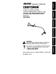
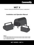
R SERIES
Loudspeakers With
Unparalleled Musicality, Superior Voice Projection
and Premium Weather Resistance
Installation and Operation Manual
Models: R.5-MAX and R2-MAX
WEATHER-RESISTANT • R-SERIES
IMPORTANT SAFETY INSTRUCTIONS
RIGGING AND ELECTRICAL SAFETY
Always follow these basic safety precautions when using
or installing R SERIES loudspeakers and accessories:
DANGER: The loudspeakers described in this manual
are designed and intended to be ‘flown’ or suspended
using a variety of rigging hardware, means, and
methods. Installation of loudspeakers should only be
performed by trained and qualified personnel. It is strongly
recommended that a licensed and certified professional
structural engineer approve the mounting design. Severe
injury and/or loss of life may occur if these products are
improperly installed! All electrical connections must
conform to applicable city, county, state, and national
(NEC) electrical codes.
•Read these instructions prior to assembly.
•Keep these instructions for reference.
•Heed all warnings.
•Follow all instructions, particularly those pertaining to
rigging, mounting, hanging and electrical connections.
•Only use attachments and accessories that are
specified and approved by the manufacturer.
•Refer all servicing to qualified service personnel.
Servicing is required when the apparatus has been
damaged in any way, such as power-supply cord or
plug is damaged, liquid has been spilled or objects
have fallen into the apparatus, does not operate
normally, or has been dropped.
The terms caution, warning, and danger may be used
in this manual to alert the reader to important safety
considerations. If you have any questions or do not
understand the meaning of these terms, do not proceed
with installation. Contact your local dealer, distributor, or
call Community directly for assistance. These terms are
defined as:
CAUTION: describes an operating condition or user
action that may expose the equipment or user to
potential damage or danger.
WARNING: describes an operating condition or user
action that will likely cause damage to the equipment
or injury to the user or to others in the vicinity.
DANGER: describes an operating condition or user
action that will immediately damage the equipment
and/or be extremely dangerous or life threatening
to the user or to others in the vicinity.
These servicing instructions are for use by qualified service
personnel only. To reduce the risk of fire or electric shock do
not perform any servicing other than that contained in the
operating instructions unless you are qualified to do so.
DANGER: R SERIES rigging fittings are rated at a
Working Load Limit of 100 lbs (45.4 kg) with a 10:1
safety margin. No single rigging fitting should ever
be subjected to a load that is greater than 100 lbs. Failure
to heed this warning could result in injury or death!
IMPORTANT: Refer to the sections on installation
and connections later in this manual for additional
information on rigging and electrical safety.
DANGER: It is possible to experience severe
electrical shock from a power amplifier. Always
make sure that all power amplifiers are in the “OFF"
position and unplugged from an AC Mains supply before
performing electrical work.
DANGER: It is essential that a safety cable (not
supplied) be utilized whenever an R SERIES
Loudspeaker is installed. The safety cable must
be secured to a suitable load-bearing point separate
from the loudspeaker mounting point, with as little
slack as possible so as not to develop undue kinetic
force if the mounting bracket (yoke) were to fail. Utilize
one of the unused threaded mounting points on the
enclosure for this purpose.
CAUTION: Installation of R SERIES loudspeakers should only be performed by trained and qualified personnel. It is strongly
recommended that a licensed and certified professional structural engineer approve the mounting. Severe injury and/or
loss of life may occur if this product is improperly installed.
Page 2
Installation and Operation Manual
R.5-MAX, R2-MAX
UNPACKING AND INSPECTION
SYSTEM INFORMATION
Community R SERIES loudspeakers are engineered and
manufactured to be rugged and they are carefully packed
in sturdy cartons. Make sure that the number of cartons
shown on the freight documents have actually been
delivered. It is wise to thoroughly inspect each unit after
it has been removed from the packaging, as damage could
occur during shipping.
PHYSICAL FEATURES / GENERAL DESCRIPTION
Please note that once the shipment has left your dealer
or the Community factory, the responsibility for damage
is always borne by the freight company. If damage has
occurred during shipping, you must file a claim directly
with the freight company. It’s very important to contact
the freight company as soon as possible after receiving
your shipment, as most freight companies have a short
time limit within which they will investigate claims. Be
sure to save the carton and the packing material, as most
claims will be denied if these materials are not retained.
Your Community dealer and the factory will try to help in
any way they can, but it is the responsibility of the party
receiving the shipment to file the damage claim.
It is always a good idea to retain the carton and packing
materials indefinitely, if possible, in the event that the unit
may need to be returned to your dealer or distributor for
repair.
IN THE CARTON
Each shipping carton contains the following items:
The R.5-MAX and R2-MAX are the premier products in the
R SERIES line. They are designed for premium quality music
reproduction with very low distortion and high output.
The R.5-MAX: This fully passive, true point source
loudspeaker produces a very flat frequency response
without external equalization. It features a 600W
neodymium LF driver with aluminum demodulation ring
and a large format 1.4" exit HF driver with copper shorting
ring and hybrid resonance damping diaphragm. It is ideal
for critical music reproduction in challenging acoustic
environment applications indoors or outdoors. Two horn
patterns are available: 60° x 60° and 90° x 60°.
The R2-MAX delivers the same great pattern control and
vocal intelligibility as a standard R2, but with the addition
of premium drivers, a signal aligned MF/HF horn, very flat
frequency response, higher broadband output, and lower
distortion. The R2-MAX features dual 12" 600W neodymium
LF drivers with aluminum demodulation rings, large
format 1.4" exit HF drivers with copper shorting rings and
hybrid, resonance damping diaphragms, and higher output
M200HP midrange compression drivers. It is ideal for critical
music reproduction in difficult acoustic environments. The
R2-MAX is a modern stadium loudspeaker, designed to
meet the needs of today’s modern sporting venues. Output
is biamp only. Three coverage patterns are available:
60° x 40°, 60° x 60° and 90° x 40°.
•One (1) R SERIES loudspeaker
•One (1) Steel mounting yoke (pre-installed)
•Multi-angle aiming strap [R.5-MAX (1), R2-MAX (2)]
•One (1) Installation and operation manual
•One (1) Warranty card
•Mounting hardware:
R.5-MAX (all models): 3/8" x 1-1/4" threaded studs
(x3), 3/8" lock washers (x3), 3/8" flat washers (x3),
and 3/8"-16 hex nuts (x3). All hardware is stainless
steel.
R2-MAX (all models): 1/2" hex bolts (2" x3, 1-1/4" x3),
1/2" lock washers (x6), 1/2" flat washers (x7),
1/2" hex nut (x1), and 2" OD rubber gaskets (x5). All
hardware is stainless steel. Much of the hardware
may be preinstalled on the enclosure.
R.5-MAX, R2-MAX
R SERIES FEATURES / TECHNOLOGY
R-MAX loudspeakers offer numerous features and
technologies that provide unprecedented sonic quality and
installation flexibility. Some of these include:
•Unique full-range high output loudspeakers with
advanced passive crossover technology
•All models are weather-resistant, UV stabilized and
suitable for outdoor direct exposure
•Protective steel grilles and mounting brackets are
covered with a rugged, zinc-rich epoxy dual-layer
powder-coat finish for superior resistance to weather
•Stainless steel hardware
•R.5-MAX models are available in black, white, or light
grey finish and R2-MAX models are available in a
light grey finish (standard). Custom colors are also
available.
Installation and Operation Manual
Page 3
PRODUCT FEATURES IDENTIFICATION
TYPICAL R.5-MAX FULL-RANGE MODEL
Safety Cable Attachment Point: (Utilize empty rigging point. User must supply appropriate fastener and safety cable)
Installer to supply hardware for
top attachment of strap to yoke
Yoke
Aiming Strap
Grille
3/8"-16 Rigging points
(sides and back)
5 Rigging Points (3/8"-16)
(sides + back)
FRONT
Gland Nut / Cable
REAR
TYPICAL R2-MAX FULL-RANGE MODEL
Safety Cable Attachment Point: (Utilize empty rigging point. User must supply appropriate fastener and safety cable)
Grille
Yoke
Angle Securing Straps
(5) 1/2"-13
Rigging points
HF/MR Connection
(white) Gland Nut
(5) 1/2"-13
Rigging points
LF Connection
(black) Gland Nut
FRONT
Page 4
Suggested Safety Cable Attachment Point
(user must supply appropriate 1/2"-13
fastener and safety cable)
Installation and Operation Manual
REAR
R.5-MAX, R2-MAX
RIGGING / SUSPENSION AND SAFETY
TERMINOLOGY: The terms “rigging", “flying" and
“suspension" are often used interchangeably to describe
the installation of loudspeaker systems above ground level.
None of these terms pertain to, or attempt to describe, the
actual method that is used (cables, brackets, chains, etc.).
DANGER: The loudspeakers described in this manual
are designed and intended to be suspended using a
variety of rigging hardware, means, and methods. It
is essential that all installation work involving the
suspension of these loudspeaker products be performed
by competent, knowledgeable persons who understand
safe rigging practices. Severe injury and/or loss of life may
occur if these products are improperly suspended.
DANGER: All rigging fittings and inserts must remain
sealed with the included hardware or they must be
fitted with properly rated optional mounting
hardware. Any missing fasteners will compromise the
weather resistance of the enclosure.
COMMUNITY RIGGING HARDWARE WARRANTY:
Community warrants that its loudspeaker systems and
its optional mounting and rigging hardware have been
carefully designed and tested. Community loudspeakers
may be safely suspended when each loudspeaker model
is suspended with Community-manufactured mounting
and rigging brackets specifically designed for use with that
particular model of loudspeaker. This warranty applies
only for use under normal environmental conditions, and
when all loudspeakers, component parts, brackets and
hardware are assembled and installed in strict accordance
with Community’s installation guidelines contained
herein. Beyond this, Community assumes no further or
extended responsibility or liability, in any way or by any
means whatsoever. It is the responsibility of the installer
to insure that safe installation practices are followed,
and that such practices are in accordance with any and
all local, state, federal, or other, codes, conditions, and
regulations that may apply to, or govern the practice of,
rigging, mounting, and construction work in the relevant
geographic territory. Any modifications made to any parts
or materials manufactured or supplied by Community shall
immediately void all pledges of warranty or surety, related
in any way to the safe use of those parts and materials.
IMPORTANT NOTES ON RIGGING LOUDSPEAKERS
There are three areas of responsibility for rigging
loudspeakers. The first is the building structure. Always
consult with the building architect or structural engineer
to assure the ability of the structure to support the
loudspeaker system. The second area of responsibility is
the loudspeaker itself. Community certifies its loudspeaker
systems and rigging accessories for suspension when
they are properly installed according to our published
guidelines. The third area of responsibility is everything
between the loudspeaker and the building structure and
the actual process of installation. The installing contractor
assumes this responsibility. Loudspeaker rigging should
be performed only by certified rigging professionals
using certified rigging hardware chosen for the specific
application. Prior to installation, the contractor should
present a rigging plan, with drawing and detailed parts
list, to a licensed structural engineer (P.E.) or architect for
written approval.
WARNING: R SERIES rigging fittings are rated at a
Working Load Limit of 100 lbs (45.4kg) with a 10:1
safety margin. No single rigging fitting should ever
be subjected to a load that is greater than 100 lbs. Failure
to heed this warning could result in injury or death!
ACCEPTABLE MOUNTING POINT LOADING
The mounting points should always be used so that either
shear force is applied perpendicular to the direction of and
in tight proximity to the mounting hole, or tension force
is applied perpendicular to the enclosure surface. See
Figure 1 below.
DANGER: Use the mounting points only as described
above. Do not use them in such a way as to apply
sideways leverage to them. Failure to follow this
instruction could result in immediate failure of the
mounting points resulting in damage to the loudspeaker
and serious injury or death to personnel
NOT Correct
Correct
Bracket spaced away
from enclosure
Yoke tight against
enclosure (R.5-MAX)
or rubber washer and
enclosure (R2-MAX)
WARNING
NON-COMMUNITY RIGGING HARDWARE:
Non-Community hardware used for rigging an
R SERIES loudspeaker must be certified by the supplier for
such use and must be properly rated for safety.
Yoke
Custom
Bracket
Enclosure
Figure 1. Mounting point load
R.5-MAX, R2-MAX
Installation and Operation Manual
Page 5
INSTALLATION
BEFORE YOU START
MOUNT THE R.5-MAX LOUDSPEAKER
q Read all instructions and gather tools necessary before
starting the installation. Please read all safety instructions
and warnings regarding rigging and installation of the
loudspeaker. The "q" preceding each step can be used to
check off each step as it is completed (or applicable).
q Attach the R.5-MAX loudspeaker to the yoke. See
Figure 2. The mounting point holes are approximately
7/16" (11mm) deep. The threaded studs used should not
extend into the hole more than 3/8" (9.5mm). Lift the
loudspeaker into place between the yoke arms. Attach as
shown. Support the enclosure until all connections are
made. Tighten bolts to finger tight (enough to hold the
loudspeaker in position).
Every effort has been made to ensure that the information
contained in this manual was complete and accurate at
the time of printing. However, due to ongoing technical
advances, changes or modifications may have occurred that
are not covered in this publication. The latest version of this
manual is always available at www.communitypro.com.
The revision date can be found on the rear cover.
The R.5-MAX and the R2-MAX have differing mounting
instructions. Please refer to the appropriate instruction for
your loudspeaker model.
WARNING: Loudspeakers are heavy. To prevent
injury or damage, they should be supported during
the mounting process until the connection is secure.
Enclosure
Yoke
3/8" SS
Lock Washer
INSTALL THE R.5-MAX
3/8" SS
Hex Nut
MOUNT THE YOKE
Attach the yoke to the support structure prior to mounting
the loudspeaker enclosure. Five (5) integral threaded
mounting points on the four sides and the back of the
enclosure line up with the yoke or can be used for a custom
fabricated mounting. The unused holes have plugs or
hardware that can be removed if these holes are needed
for mounting or attaching the aiming strap.
Notes: The plugs are purposely designed to "catch" on the
mounting point threads and may be somewhat difficult
to remove. All unused holes must be filled with either
the supplied hardware or plugs to maintain the weatherresistance of the enclosure. The R.5-MAX has threaded
studs rather than hex head bolts as the supplied mounting
hardware.
q Determine the appropriate location and orientation,
and mount the yoke to the support structure. Hardware to
mount the yoke to the structure is not included and should
be specified by a structural engineer, load-rated for the
intended use, and be suitably weather-resistant.
Note: If the center hole is used to mount a yoke on the
R.5-MAX, the angle securing strap must also be attached
as shown in Figure 3 prior to securing the hardware.
Page 6
Rigging Points
(if unused, plug with 5/16" plugs)
3/8" SS Flat Washer
3/8"-16 x 1-1/4" SS Stud
(leave 3/4" sticking out)
Figure 2. Mount the R.5-MAX loudspeaker to the yoke
SECURE THE ANGLE
q Determine the approximate angle of downward tilt.
It must be angled at least 15° down from horizontal to
maintain the stated enclosure EIEMA rating and reduce the
possibility of rain and other precipitation compromising
the performance. Bend and attach the angle securing
strap(s) as shown in Figure 3. Hardware to attach the
strap to the yoke is not included and should be supplied
by the installer and be suitably weather resistant. Tighten
the yoke hardware until sufficiently tight enough to hold
the angle. Do not use excessive force when tightening
mounting hardware.
ATTACH SAFETY CABLE
q Attach a safety cable to one of the open mounting
points (see Product Features page 4). The safety
cable and hardware are not included. Please consult a
structural engineer for the appropriate cable for the load
and application. The safety cable must be secured to a
suitable load-bearing point separate from the loudspeaker
mounting point, with as little slack as possible, so as not to
develop undue kinetic force if the loudspeaker mount were
to fail.
Installation and Operation Manual
R.5-MAX, R2-MAX
R.5-MAX
Yoke
0°
Securing Strap
X°
Angle Securing Strap
(determine approximate
hole to use based on
chart at right)
11
10
9
8
7
6
5
4
3
2
1
3/8" SS Flat Washer
3/8" SS Hex Nut
3/8" SS Lock Washer
3/8"-16 x 1-1/4" SS Stud
(leave 3/4" sticking out)
Hardware to secure the strap to the yoke
appropriate for yoke attachment to the
structure must be supplied by the installer
Hole #
1
2
Down Angle
3°
6°
3
4
5
6
7
8
9
10
11
14° 18° 20° 25° 29.5° 36° 41.5° 47° 50°
Figure 3. Attach the angle securing strap to the R.5-MAX
INSTALL THE R2-MAX
WARNING: Loudspeakers are heavy. To prevent
injury or damage, they should be supported during
the mounting process until the connection is secure.
q The R2-MAX loudspeaker is shipped with the yoke
attached. If it is necessary to position the yoke differently,
please remove the mounting hardware and reserve the
hardware for repositioning. Attach the R2 loudspeaker
to the yoke. See Figure 4a. Determine and orient the
loudspeaker correctly for the coverage desired for your
application. Mount the loudspeaker to the yoke with the
rubber washers between the yoke and enclosure and
attach as shown. This is intentionally a tight fit to maintain
weather resistance. Tighten bolts to finger tight (enough to
hold the loudspeaker in position).
q Attach the short flat end of the contour strap to the
mounting point located at the back/center of the enclosure
bell using the bolt, rubber washer, flat washer, and lock
washer supplied in the mounting point. Make sure that
the rubber washer is between the contour strap and the
enclosure. See Figure 4b. Leave the other end (the long
flat end) of the contour strap temporarily unattached.
Eventually this will be attached to the mounting point
below where the yoke crossbar is positioned when the
loudspeaker is mounted and aimed properly.
The short flat end of the contour
strap goes to the rear and the long
flat end should be attached to one
of the side mounting points.
1/2" SS
Lock Washer
Contour Strap
1/2"-13 SS
Hex Bolt
1/2" x 1-1/4"
SS Hex Bolt
1/2" SS Lock Washer
1/2" SS Flat Washer
1/2" SS Flat Washer
2" OD Rubber Gasket
2" OD
Rubber Gasket
Figure 4a. Mount the R2-MAX loudspeaker to the yoke
R.5-MAX, R2-MAX
Figure 4b. Attach the contour strap
Installation and Operation Manual
Page 7
R2-MAX INSTALLATION (cont'd)
q Mount the R2-MAX and yoke to the support structure.
If the center hole is being used to mount the yoke, that
hardware must be installed before attaching the securing
strap to the yoke. All mounting hardware must be supplied
by the installer and be weather-resistant and properly
rated for the weight and potential wind load by a structural
engineer.
q Attach the free end of the contour strap to the enclosure
as shown in Figure 5b. Make sure that the rubber washer is
located between the contour strap and the enclosure.
Contour Strap
1/2" x 1-1/4" SS Hex Bolt
Fig 5a
Fig 5b
1/2" SS Lock Washer
Fig 5c
1/2" SS Flat Washer
Fig 4a
Fig 4b
2" OD Rubber Gasket
Figure (connection) reference key
q Attach the securing strap to the yoke. Align the short bent
end with the 9/16" hole with the yoke, and attach as shown
in Figure 5a. The securing strap should be positioned on
the yoke crossbar with the long end positioned over the
contour strap.
1/2" SS
Lock Washer
1/2"-13
SS Hex Nut
1/2" SS
Flat Washer
1/2" x 2"
SS Hex Bolt
Yoke
Angle
Securing Strap
Figure 5b. Attach the contour strap to the enclosure
q Fully attach the securing strap to the contour strap as
shown in Figure 5c. First ensure that the loudspeaker is
aimed at the appropriate angle. Bend the securing strap
towards the enclosure to put it on the bolt previously
installed on the contour strap. You will have to bend the
securing strap towards the enclosure to put it on the
bolt. First place one of the 1/4" flat washers on the bolt,
followed by the securing strap. Finish with the remaining
1/4" flat washer, 1/4" lock washer, then secure with a
1/4"-20 hex nut.
Attach the 1/4" hardware to the holes
that best match the angle desired
Figure 5a. Attach the securing strap to the yoke
q Determine the approximate angle of downward tilt and
adjust the angle accordingly. It must be angled at least 5°
down from horizontal to maintain the stated enclosure
EIEMA rating and reduce the possibility of rain and other
precipitation compromising the performance. Once the
aiming angle is set, bend the securing strap against the
contour strap. The series of holes in the securing strap
should line up with one of the three 5/16" (8 mm) holes
in the contour strap. This determines where to locate the
bolt in the contour strap to attach the securing strap. Lift
the contour strap away from the R2 enclosure and put
the 1/4"-20 x 1" (25 mm) stainless steel bolt in this hole
so that the bolt head is between the contour strap and
the enclosure. Secure it with a lock washer and hex nut as
shown at right
Page 8
Contour Strap
Angle Securing Strap
1/4" SS Lock Washer
1/4"-20 SS Hex Nut
1/4" SS Flat Washer
1/4"-20 SS Hex Nut
1/4" x 1" SS Hex Bolt
Figure 5c. Attach the securing strap to the contour strap
Installation and Operation Manual
R.5-MAX, R2-MAX
WIRING AND ELECTRICAL SAFETY
All standard R-MAX loudspeakers come with attached
SJOW rated input cables, 12' (3.6m) in length. The cable
enters the enclosure through a waterproof gland nut. The
other end of the cable is un-terminated. Beyond this length,
line-loss calculations should be performed when selecting
additional wiring to prevent losses in output due to voltage
drops resulting from increased impedance. Please contact
Community’s TAG Team (Technical Applications Group) for
additional assistance (email: [email protected],
phone: (610) 876-3400, or toll-free (800) 523-4934 in the
US and Canada).
q Wire the loudspeaker. A typical installation method is
to bring the cable into a waterproof junction box (J-box)
equipped with a waterproof gland nut. Connections within
the J-box may be made with barrel-type crimp connectors,
wire nuts, solder and heat-shrink, or terminal strips.
Terminate per your local electrical code.
STANDARD WIRING (R.5-MAX)
Connect as shown in Figure 6.
(–) ( Black)
(+) ( White)
Figure 6. Standard wiring
BIAMP WIRING
All R2-MAX are biamp models and have color coded gland
nuts (and a label on the enclosure - see Figure 7 below)
that will indicate what input the cable is designated for.
The cables are 2-conductor standard weather-resistant
cables 12' (3.6m) in length.
MF/HF connection
(white gland nut)
We recommend using barrel-type crimp connectors
that are crimped with a forged crimp tool (such as
Klein 1005) or a ratcheting tool (such as Klein T1720), as
this method, when properly executed, results in a gastight connection that is quick and easy to accomplish.
IMPORTANT: All electrical installation connections
for loudspeaker lines are subject to all applicable
governmental building and fire codes. The selection
of appropriate electrical hardware to interface with the
R SERIES loudspeaker lies solely with the installation
professional.
Community
recommends
that
an
appropriately licensed engineer, electrician, or other
qualified professional identify and select the appropriate
conduit, fittings, wire, etc. for the installation.
DANGER: The output power capabilities of audio
amplifiers present a danger to installers. To
minimize the risk of electric shock from
loudspeaker connecting cables, confirm that the power
amplifiers are turned “off" before connecting loudspeaker
cable(s) to the loudspeaker or amplifier. Always follow
local electrical codes and proper electrical safety
procedures.
WARNING: After wiring the amplifier(s) to the
loudspeaker(s), first power-up all devices that are
upstream of the amplifier, such as mixers,
equalizers, compressor/limiters, etc., before powering-up
the amplifier. This is to avoid passing any clicks or pops that
may originate in the upstream devices to the loudspeakers.
The amplifier should initially be powered-up with its gain
controls turned all the way down. After making sure that a
continuous signal is present, such as a CD playing, slowly
raise the level of the gain controls to establish that the
wiring has been installed correctly. Only then should the
loudspeaker be operated at normal output levels.
R.5-MAX, R2-MAX
LF connection
(black gland nut)
Figure 7. Labeled cables - R2-MAX
FINAL ASSEMBLY AND TESTING
q All holes should be filled with the provided hardware or
other suitable replacement in order to maintain weatherresistance.
q Attach a safety cable to an attachment point on each
loudspeaker. The safety cable and hardware are not
included. Please consult a structural engineer for the
appropriate cable for the load and application. The safety
cable attachment points should not be located on opposite
sides of the cabinet in such a manner that they present a
significant force that pulls the insert points away from each
other. The safety cable must be secured to a suitable loadbearing point separate from the loudspeaker mounting
point, with as little slack as possible, so as not to develop
undue kinetic force if the R SERIES mounting were to fail.
q Power and test the system.
Installation and Operation Manual
Page 9
MAINTAINING WEATHER RESISTANCE
SERVICE AND SUPPORT
GUIDELINES FOR R SERIES OUTDOOR USE
INFORMATION AND APPLICATION ASSISTANCE
R SERIES is suitable for outdoor direct exposure installation
when used as recommended. For best results in outdoor
applications, follow these guidelines:
For more information on installing and operating your
R SERIES loudspeaker, please refer to Community’s web
site at communitypro.com. For application support, service
or warranty information, refer to Community’s web site or
contact Community's TAG Team (Technical Applications
Group) for additional assistance at 610-876-3400 or tollfree (US and Canada) at 800-523-4934.
•Always orient the loudspeaker so the mouth of the
horn is, at a minimum, pointing at least 5 degrees
downward. Failure to do this could result in water
collecting inside the enclosure under extreme weather
conditions.
•When handling an R SERIES loudspeaker, be careful not
to scratch or scrape the finish on the grille, bracket, or
enclosure.
To obtain specific warranty information and available
service locations for countries other than the United States
of America, contact the authorized Community Distributor
for your specific country or region.
•All mounting holes must be sealed off with the plugs
or stainless steel bolts, washers, and rubber washers
supplied. If, for any reason, the hardware must be
removed, seal off the hole with silicone caulking or
some other suitable weather-tight sealant.
•The rubber washers supplied with the mounting bolts
must always seat against the enclosure (R2-MAX only).
•The grille assembly is designed to prevent normal and
wind-driven rain from directly entering the mouth of
the loudspeaker. The grille is not designed to withstand
such things as being directly sprayed from a hose;
therefore this should be avoided.
•If you use any hardware in place of hardware provided
with your R SERIES loudspeaker, it should also be made
of stainless steel.
Page 10
Installation and Operation Manual
R.5-MAX, R2-MAX
SPECIFICATIONS
R.5-66 MAX
R.5-96 MAX
Loudspeaker Type:
2 way, full-range, coaxial
2 way, full-range, coaxial
Driver Complement:
LF: 1 x 12" with neodymium motor and
aluminum demodulation ring
HF: 1 x 1.4" exit compression driver
with 2.87" voice coil
LF: 1 x 12" with neodymium motor and
aluminum demodulation ring
HF: 1 x 1.4" exit compression driver
with 2.87" voice coil
70 Hz to 20 kHz (-10 dB)
70 Hz to 20 kHz (-10 dB)
95 Hz to 19 kHz (-3 dB)
95 Hz to 20 kHz (-3 dB)
600W RMS, 1200W Program
69 volts RMS, 138 volts momentary peak
600W RMS, 1200W Program
69 volts RMS, 138 volts momentary peak
131 dB (137 dB Peak)
130 dB (136 dB Peak)
130 dB (136 dB Peak)
129 dB (135 dB Peak)
Sensitivity (1W / 1m)
Free Space SPL3,5:
103 dB (125 Hz - 10 kHz)
103 dB (250 Hz - 4 kHz)
102 dB (125 Hz - 10 kHz)
103 dB (250 Hz - 4 kHz)
Nominal Impedance:
8 ohms, 4.8 ohms @ 200 Hz minimum
8 ohms, 4.8 ohms @ 200 Hz minimum
Nominal Beamwidth (-6dB):
60° x 60°, 1.6 kHz to 10 kHz
90° x 60°, 1.6 kHz to 10 kHz
Axial Q / DI:
18.7/12.7, 1.6 kHz to 10 kHz
13.8/11.4, 1.6 kHz to 10 kHz
Operating Range1:
Frequency Response1:
Max Input Ratings:
Maximum Output2
without EQ3:
with EQ4:
Crossover Frequency:
Recommended Processing6:
Recommended Amplifier:
Input Connection:
Controls:
Rigging Provisions:
Construction:
900 Hz
DSP with CONEQ™ power response correction
1200W to 1800W at 8 ohms
12 foot (3.6m) SJOW #16-2 cable
None
Five 3/8"-16 rigging points, Zinc-rich epoxy dual-layer powder-coated yoke
Rotomolded LLDPE plastic
Finish:
Black, White or Light Grey (RAL# 9004, 9003, 7038)
Grille:
3-layer Weather-Stop™ with polyester mesh, foam, zinc-rich epoxy dual-layer powder-coated
perforated steel color-matched to enclosure
Environmental:
Dimensions H x W x D:
Net weight:
IP55W per IEC 529 at 5° down-tilt, Designed to MIL-STD-810G
16" x 16" x 16.19" (406 x 406 x 411 mm)
44 lbs (20 kg) loudspeaker only, 47 lbs (21.3 kg) with yoke bracket
1. Operating range and frequency response parameters are stated with DSP equalization applied.
2. Calculated based on power rating and sensitivity, exclusive of power compression.
3. Raw driver or system response prior to applying any filters for frequency response or power response correction.
4. Recommended equalization as published in the Community Loudspeaker Library within Community's Resyn™ software.
5. Free field anechoic sensitivity, calculated using input voltage that would produce 1W at the nominal impedance.
6. Community's dSPEC226 loudspeaker signal processor DSP and Resyn™ software include CONEQ™ 1000 point FIR filter power response correction filters within the
preconfigured speaker file for this model of loudspeaker.
Community strives to improve its products on a continual basis. Specifications are therefore subject to change without notice.
Note: Every effort has been made to insure that the information contained in this manual was complete and accurate at the time of
printing. However, due to ongoing technical advances, changes or modifications may have occurred that are not covered in this manual.
Visit Community at http://www.communitypro.com for the latest version of this manual and the most recent product information.
R.5-MAX, R2-MAX
Installation and Operation Manual
Page 11
SPECIFICATIONS
R2-64 MAX
R2-66 MAX
R2-94 MAX
SYSTEM
TRANSDUCERS
LF:
MF:
HF:
2 x 12" inherently weather-resistant cones with 3" voice coil, neodymium motor and aluminum demodulation ring
1 x 2" exit, M200HP compression, 3.5" diaphragm, 2.2" Voice coil, high temp non-metallic diaphragm
1 x 1.4" exit compression, 2.87" voice coil, copper shorting ring, titanium diaphragm with mylar surround
Operating Mode:
Biamp (Passive MF/HF)
Operating Range1:
70 Hz to 22 kHz (-10 dB)
70 Hz to 22 kHz (-10 dB)
70 Hz to 22 kHz (-10 dB)
Frequency Response1:
85 Hz to 18 kHz (-3 dB)
85 Hz to 20 kHz (-3 dB)
85 Hz to 20 kHz (-3 dB)
60° x 40°, 1.6 kHz to 10 kHz
60° x 60°, 1.6 kHz to 10 kHz
90° x 40°, 1.6 kHz to 10 kHz
24.89/13.96, 1.6 kHz to 10 kHz
17.13/12.34, 1.6 kHz to 10 kHz
14.75/11.69, 1.6 kHz to 10 kHz
133 dB (139 dB Peak)
132 dB (138 dB Peak)
133 dB (139 dB Peak)
132 dB (137 dB Peak)
132 dB (137 dB Peak)
131 dB (136 dB Peak)
Nominal Beamwidth (-6dB):
Axial Q / DI:
Maximum Output
without EQ3:
with EQ4:
2
Crossovers5
LF:
MF:
Passive MF/HF:
Recommended Processing6:
4th order (24 dB/oct) 450 Hz, Active
8th order (48 dB/oct) 450 Hz, Active
8th order (48 dB/oct) 3.3 kHz
DSP with CONEQ™ power response correction
PERFORMANCE
Maximum Input Ratings
LF:
MF/HF:
Sensitivity7 LF:
MF/HF:
1200W Continuous (98V) / 4800W Peak (196V)
150W Continuous (35V) / 300W Peak (70V)
103 dB (100 Hz - 500 Hz)
108 dB (400 Hz - 18 kHz)
103 dB (100 Hz - 500 Hz)
108 dB (400 Hz - 18 kHz)
103 dB (100 Hz - 500 Hz)
107 dB (400 Hz - 18 kHz)
Maximum Output8
(without EQ)3 LF:
MF/HF:
134 dB (140 dB peak)
130 dB (136 dB peak)
134 dB (140 dB peak)
130 dB (136 dB peak)
134 dB (140 dB peak)
129 dB (135 dB peak)
(with EQ)4 LF:
MF/HF:
133 dB (139 dB peak)
129 dB (135 dB peak)
133 dB (139 dB peak)
129 dB (135 dB peak)
133 dB (139 dB peak)
128 dB (134 dB peak)
Nominal Impedance
LF:
MF/HF:
SYSTEM
Input Connection:
Enclosure:
Finish:
Rigging Provisions:
Grille:
Environmental:
Dimensions – H x W x D:
Loudspeaker Unit Weight:
8 ohms, (9.3 ohms @ 250 Hz minimum)
8 ohms, (5.6 ohms @ 5 kHz minimum)
2 x 12' (3.6 m) 16-2 SJOW cables
Hand-laminated multilayer fiberglass
Paintable, light grey gel-coat (RAL #7038)
(5) 1/2"-13 rigging points; Steel zinc-rich epoxy dual-layer powder-coated bracket;
(2) Aluminum aiming straps to secure angle
3-layer Weather-Stop™ with polyester mesh, foam, and zinc-rich epoxy dual-layer powder-coated
perforated steel, color-matched to enclosure
IEC529 IP55W rating with a minimum 5° down-tilt, Designed to MIL-STD-810G
24.75" x 24.75" x 30.75" (629 x 629 x 781 mm)
92 lbs (42.2 kg) loudspeaker only, 115 lbs (52.2 kg) with yoke bracket
1. Operating range and frequency response parameters are stated with DSP equalization applied.
2. Calculated algebraic sum of LF and passive MF/HF with recommended active crossover based on power rating and sensitivity, exclusive of power compression.
3. Raw driver or system response prior to applying any filters for frequency response or power response correction.
4. Recommended equalization as published in the Community Loudspeaker Library within Community's Resyn™ software.
5. Resultant engineered acoustical response of crossover network and components.
6. Community's dSPEC226 loudspeaker signal processor DSP and Resyn™ software include CONEQ™ 1000 point FIR filter power response correction filters within the
preconfigured speaker file for this model of loudspeaker.
7. Free field anechoic sensitivity, calculated using input voltage that would produce 1W at the nominal impedance.
8. Calculated based on power rating and sensitivity, exclusive of power compression.
Page 12
Installation and Operation Manual
R.5-MAX, R2-MAX
R-MAX SPEC SHEET PROCESSING DETAILS
COMMUNITY LOUDSPEAKER DATA: “TRUE TO SPECIFICATION”
Ever since Community pioneered the measurement and publication of detailed loudspeaker specifications in 1976, we
have striven to present the most relevant, useful, and technically correct loudspeaker data to our customers. Community
believes that our customers are best served by having published data and specifications that accurately depict the real world
performance of our loudspeaker systems and work properly with computer-based loudspeaker modeling software.
In the beginning, this was an easy task. Community’s engineers provided the data and we published it with no modifications. As
time progressed, however, other loudspeaker manufacturers’ marketing departments began to evaluate their specifications
prior to publication to make sure that their loudspeakers were presented in the best possible way. This often meant omitting
specifications that were not flattering in competitive comparisons. Some manufacturers have now taken these marketing
specs to extremes, while others simply leave out important details needed to convey the full loudspeaker performance
characteristics.
In contrast, Community continues to present its data in a “full-disclosure”, detailed engineering format. Professional
designers and end users appreciate this approach, but some customers may not have the time or expertise to compare
spec sheets, validate the numbers, and then sit back and ask themselves, “Did what I just read make sense? Does it all add
up?” Unfortunately, when this happens, the manufacturer with the most inflated, unrealistic numbers and the most highly
smoothed (and sometimes DSP processed without annotation) frequency responses may appear to be the best choice. That
is, until the loudspeakers are installed in the field and don’t meet expectations.
Thus, for Community’s R-MAX loudspeaker product line, we chose the approach that allows us to present our specifications
in the traditional “full-disclosure” format while also providing them in a more competitive format that allows our products to
be directly compared to other manufacturers.
EQUALIZED VS. UN-EQUALIZED OUTPUT SPL
Here’s an example. As shown in Figure 8, R-MAX spec sheets include Maximum Output SPL for each model with and without
equalization.
Maximum Output2
without EQ3: 133 dB (139 dB Peak)
with EQ4: 132 dB (138 dB Peak)
Figure 8. R2-64MAX “Maximum System Output” ratings from the spec sheet
In contrast, most manufacturers provide only the Maximum Output SPL without EQ. This is a glaring omission because,
once the loudspeaker has been equalized, its Maximum Output SPL can only be as high as the output of its least powerful
component (transducer). For example, in a 3-way loudspeaker, the passive MF/HF Maximum Output SPL may be stated as
“134 dB”. But, if the MF is 10 dB higher in output than the HF, the equalized Maximum Output SPL may be 5-10 dB lower than
this single number. In many cases the LF output is a few dB lower still, reducing the loudspeaker’s overall equalized Maximum
Output SPL even further.
Community purposely designed the R-MAX series with drivers that have well-matched outputs. Thus, R-MAX models do not
require excessive equalization and that means the overall Maximum Output SPL of an equalized vs. un-equalized R-MAX
loudspeaker does not change by more than a dB for any model. This is an important differentiating feature of R-MAX Series
specifications – the Maximum Output SPL that is achievable in the real world before and after processing is clearly stated
on the spec sheet. Designers will not have to piece together data from multiple documents to tell their customers what kind
of performance to expect. Community has made it clear and unambiguous. But this is not the only type of equalization that
reduces Maximum Output SPL and becomes a hidden omission on some spec sheets.
LOW FREQUENCY “BOOST” EFFECT ON OUTPUT SPL
In many cases, the equalized loudspeaker response shown on a spec sheet includes significant boost applied to the lowfrequency driver to increase LF extension. However, every dB of LF boost reduces the loudspeaker’s overall Maximum Output
SPL by approximately the same amount. This means that the LF driver is likely to reach its excursion limit (and/or activate the
system limiter) before the loudspeaker’s specified maximum power level has been applied.
For example, consider a loudspeaker system with the following LF driver parameters: 97 dB 1W/1m sensitivity, 2000 watts
(63V @ 2 Ohms) maximum input and a calculated Maximum Output SPL of 130 dB SPL. While not explicitly stated on the spec
sheet, the processor settings downloaded from the manufacturer’s website specify a +6 dB boost at 70 Hz, via a parametric
EQ (PEQ) filter, to achieve the LF response shown in the spec sheet’s frequency response graph.
R.5-MAX, R2-MAX
Installation and Operation Manual
Page 13
LOW FREQUENCY “BOOST” EFFECT (continued)
Now, as a thought experiment, imagine that we apply the specified maximum of 63 Volts to the entire loudspeaker before
applying the recommended +6 dB boost at 70 Hz. The entire bandwidth of the loudspeaker would then be operating at its
2000 watt limit. Now, add the +6 dB boost at 70 Hz into the signal chain. The flat portion of the driver pass band will still be
receiving 63V, but at 70 Hz the voltage will be 6 dB higher, or about 127V, which is the equivalent of about 8000 watts! Clearly,
the LF driver cannot handle 8000 watts continuously, so some compromise must be made.
To protect the LF driver from over excursion or thermal damage, we’ll need to limit the voltage at 70 Hz to the specified
maximum of 63V (2000 watts). Since we’ve boosted 70 Hz with the +6 dB PEQ filter, this is the only frequency that is able to
reach the full 2000 watt input. The remainder of the loudspeaker’s pass band will receive 6 dB less input voltage, or about
32V, which corresponds to only 500W. Figure 9 illustrates the situation.
1818
32V + 6dB = 63V (2000W)
applied to driver at 70 Hz
1212
Non-boosted portion
of driver has only 32V
(500W) applied
+6dB
66
+0dB
00
‐6-6
-12
‐12
-18
‐18
10
100
1000
Frequency (Hz)
‐24
Figure 9. Generic DSP EQ transfer function with +6 dB @ 70 Hz boost
‐30
With any loudspeaker, for every 3‐36dB of LF boost, the resultant maximum amount of power available to the flat portion of
the pass band is cut in half. And, 6 dB10of boost results in one 100
quarter of the original power.
For our example loudspeaker, this
1000
means the Maximum Output SPL in the flat portion of the pass band is reduced from 130 dB down to 124 dB.
Most manufacturers’ spec sheets do not discuss the EQ transfer function used to create the frequency response curve
and they may not disclose the LF boost that has been applied. This makes it difficult or impossible to determine the actual
Maximum Output SPL with EQ. Sometimes, the spec sheet will show “unprocessed” and “processed” response curves. These
provide some indication of the LF boost. However, it is still time consuming to calculate the actual LF boost and its effect on
Maximum Output SPL. Complicating matters further, acoustic simulation and coverage prediction software does not usually
account for the differences in real-world output that occur as the result of this LF boost, even when the EQ filters are included
in the loudspeaker source file. Modern acoustic simulation software predicts loudspeaker system results so well that many
users may not realize they have overlooked the effect of EQ boost until the system has been installed and it either cannot
reach the intended output levels, or the LF extension must be reduced in order to achieve the output levels.
COMMUNITY’S ALTERNATE APPROACH
As a contrast to the competitive loudspeaker in our thought experiment, Figure 10 shows the published response curves,
with notation, for Community’s R2-64MAX.
Note the asterisk after “(processed multi-amp*)”. This refers the reader to the explanation you are now reading. These R-MAX
curves include LF boost to produce the result shown in the frequency response chart. However, other manufacturers may
use much greater boost (in excess of 6 dB) to achieve their published results.
Frequency Response Resolution >180Hz ~ 12Hz, <180Hz ~ 3Hz, 1/6 Octave Smoothing, 1W
FREQUENCY RESPONSE
(processed multi-amp*)
Frequency Response (EQ3)
1/6 Octave Smoothing
— Complete, — High Frequency — Low Frequency 1/6 Octave Smoothing
120
120
110
110
1/6 Octave Smoothing, 1W/1m
— High Frequency — Low Frequency
110
110
Amplitude (dB SPL)
Amplitude (dB SPL)
Amplitude (dB SPL)
Amplitude (dB SPL)
120
120
FREQUENCY
RESPONSE (unprocessed)
High Frequency
Low Frequency
100
100
90
90
80
80
100
100
90
80
80
70
70
10
10
100
100
Frequency (Hz)
1000
1000
Frequency (Hz)
10000
10000
70
70
10
10
100
100
Frequency (Hz)
1000
1000
10000
10000
Frequency (Hz)
Figure 10. R2-64MAX Spec Sheet Frequency Response Graphs
Page 14
Installation and Operation Manual
R.5-MAX, R2-MAX
COMMUNITY'S ALTERNATE APPROACH (continued)
In the spirit of our efforts to offer “full-disclosure” specifications and DSP settings, we limited the R-MAX LF boost to no more
than 6 dB. Figures 11 and 12 show a comparison of the R2-64MAX with and without the 6 dB LF EQ boost, and the EQ transfer
function for each.
R2-64MAX FREQUENCYFrequency Response (EQ1)
RESPONSE, +6dB @90Hz BOOST
1/6 Octave Smoothing
1/6 Octave Smoothing
120
1/6 Octave Smoothing
1/6 Octave Smoothing
120
120
110
110
Amplitude (dB SPL)
Amplitude
(dB SPL)
110
Amplitude (dB SPL)
Amplitude
(dB SPL)
R2-64MAX FREQUENCY
RESPONSE, NO LF BOOST
Frequency Response (EQ2)
+6dB
100
100
100
90
90
90
90
80
80
80
80
70
10
10
100
Frequency
(Hz)
Frequency (Hz)
1000
1000
10000
70
70
10
100
100
Frequency
(Hz)
Frequency (Hz)
1000
10000
10000
Figure 11. R2-64MAX frequency response graphs with / without +6 dB @ 90 Hz boost
R2-64MAX DSP EQ, +6dB @90Hz
BOOST
R2‐64MAX EQ TF2
R2-64MAX DSP EQ, NO LF BOOST
R2‐64MAX EQ TF1
20
20
20
10
10
10
+6dB
00
0
‐10
-10
-10
‐10
‐20
-20
-20
‐20
‐30
-30
-30
‐30
‐40
-40
1010
100
100
1000
1000
10000
10000
-40
‐40
10
10
100
100
1000
1000
10000
10000
Frequency (Hz)
Frequency (Hz)
Figure 12. R2-64MAX DSP EQ transfer functions with / without +6 dB @ 90 Hz boost
For the R2-MAX loudspeakers, the difference in LF extension with and without the LF boost is fairly subtle; the R2 Woofers
and LF horn work very well without equalization to create natural extension and high efficiency. The published R2-MAX
equalization curves all contain an optional PEQ filter that adds 6 dB at 90 Hz. (In the Resyn™ Software Loudspeaker Library
for Community’s dSPEC226 processor, this LF boost filter is included, but bypassed by default). In applications that do not
require the full output of the loudspeaker, the designer may choose to include the LF boost. However, this will reduce the
safe, equalized Maximum Output SPL from an R2-MAX by 6 dB. In the case of the R2-64MAX, the Maximum Output SPL
would be reduced from 132dB to 126dB.
R.5-MAX, R2-MAX
Installation and Operation Manual
Page 15
COMMUNITY'S ALTERNATE APPROACH (continued)
Both R.5-MAX products also use 6dB of LF boost to create the “Processed” Frequency Response graphs shown on the
spec sheets. Figure 13 shows the response curves, with notation, for the R.5-66MAX and Figure 14 shows the R.5-66MAX
frequency response with and without the 6dB of LF boost applied:
FREQUENCY RESPONSE (processed*)
Frequency Response (EQ3)
120
120
FREQUENCY RESPONSE (unprocessed)
Frequency Response
1/6 Octave
Smoothing
1/6 Octave Smoothing
100
100
100
100
Amplitude
(dB SPL)
Amplitude (dB SPL)
110
110
Amplitude
(dB SPL)
Amplitude (dB SPL)
110
110
90
90
80
80
70
70
10
10
100
100
Frequency (Hz)
Frequency
(Hz)
1000
1000
90
90
80
80
70
70
10000
10000
1/6 Octave Smoothing, 1W/1m
Resolution >180Hz ~ 12Hz, <180Hz ~ 3Hz, 1/6 Octave Smoothing, 1W/1m
120
120
10
10
100
100
1000
Frequency (Hz)
Frequency (Hz)
10000
10000
1000
Figure 13. R.5-66MAX Spec Sheet Frequency Response Graphs
R2-64MAX FREQUENCY RESPONSE, +6dB @90Hz BOOST
Frequency Response (EQ2)
120
120
1/61/6 Octave Smoothing
Octave Smoothing
Amplitude (dB SPL)
Amplitude
(dB SPL)
Amplitude (dB SPL)
Amplitude
(dB SPL)
Frequency Response (EQ1)
1/61/6 Octave Smoothing
Octave Smoothing
120
120
110
110
110
110
+6dB
100
100
100
100
90
80
70
70
R2-64MAX FREQUENCY RESPONSE, NO LF BOOST
90
80
70
10
10
100
Frequency
(Hz)
Frequency (Hz)
1000
10000
10
10
100
100
Frequency
(Hz)
Frequency (Hz)
10000
10000
1000
1000
Figure 14. R2-64MAX frequency response graphs with / without +6 dB @ 90 Hz boost
As with the R2-MAX, the difference with and without the LF boost applied is fairly subtle and is an indication of Community’s
design philosophy of well-matched components. The LF boost simply serves to “square off” the response knee above the
high pass filter. The published R.5-MAX equalization curves contain an optional PEQ filter that adds 6 dB at 120 Hz. (In the
Resyn™ Software Loudspeaker Library for Community’s dSPEC226 processor, this LF boost filter is included, but bypassed
by default). In applications where the full output of the loudspeaker is not required, the designer may choose to include
the LF boost. However, this reduces the safe, equalized Maximum Output SPL by 6 dB. In the case of the R.5-66MAX, the
maximum output would be reduced from 130 dB to 124 dB.
We hope that this clear explanation of the R-MAX specification numbers and graphs, will allow the system designer and
system commissioner to have enough information to clearly state expectations to their customers and achieve the promised
results. Please contact Community with any questions; ph: (610) 876-3400, or by email at [email protected]
Page 16
Installation and Operation Manual
R.5-MAX, R2-MAX
TECHNICAL DRAWINGS
TYPICAL R.5-MAX COAXIAL LOUDSPEAKER
8"
(203mm)
16" (406mm)
(5) 3/8"-16
Threaded Inserts
.2" (5mm)
10.2"
(259mm) typ
Center of
Gravity
9" (229mm)
9"
(229mm)
16.39" (416mm)
Ø 0.45" (Ø 12mm)
hole x 4
Center Line
Top
8.2" (208mm)
Ø 0.55" (Ø 14mm) Center only
2"
(51mm)
1" (25mm)
4.63" (117mm)
2.75" (70mm)
4.63" (117mm)
2.75" (70mm)
NOTE: YOKE MOUNT
AND MEASURMENTS
NOTE:
YOKE MOUNT
A .125"
[3MM] TOLER
AND
MEASURMENTS
A .125" [3MM] TOLER
Yoke Dimensions
16.19"
(411mm)
16"
(406mm)
15.94"
(405mm)
8"
(203mm)
Center of
Gravity
7.63"
(194mm)
Sides
R.5-MAX, R2-MAX
Center of
Gravity
16"
(406mm)
8"
(203mm)
Front
Installation and Operation Manual
Rear
Page 17
TECHNICAL DRAWINGS
TYPICAL R2-MAX COAXIAL LOUDSPEAKER
13.5"
(343mm)
8"
(203mm)
8"
(203mm)
Center of
Gravity
Ø .53" (Ø 13.5mm) typ.
Top
30.75"
(781mm)
Yoke
24.75" (629mm)
17.25"
(438mm)
12.38"
(314mm)
15.43"
(392mm)
12.38"
(314mm)
24.75"
(629mm)
Center of
Gravity
Rear
Page 18
(5) 1/2"-13
Threaded Inserts
Sides
Installation and Operation Manual
Center of
Gravity
Front
R.5-MAX, R2-MAX
ACCESSORIES (for R.5-MAX only)
Pole mount bracket kit for mounting a
single R.25, R.5, RMG-200A, W2-218,
W2-228, W2-2W8 or W2-2V8
loudspeaker. Vertical downtilt to 90°.
PMB-1RR
Pole mount bracket kit for mounting
one (1) R.25, R.5, RMG-200A, W2-218,
W2-228, W2-2W8 or W2-2V8
loudspeaker, or two (2) loudspeakers
in a "top-bottom" configuration, with
left-to-right panning capability and
vertical downtilt.
PMB-2RR
WARRANTY INFORMATION
TRANSFERABLE WARRANTY “(LIMITED)" VALID IN
THE USA ONLY
The R SERIES Loudspeaker Systems are designed and
backed by Community Professional Loudspeakers. For
complete warranty information please visit our website
at www.communitypro.com/warranty. Please call
610-876-3400 to locate your nearest Authorized Field
Service Station. For Factory Service call 610-876-3400. You
must obtain a Return Authorization (R/A) number prior to
the return of your product for factory service.
WARRANTY INFORMATION AND SERVICE FOR
COUNTRIES OTHER THAN THE USA
To obtain specific warranty information visit the website
www.communitypro.com/warranty. To obtain available
service locations for countries other than the United States
of America, contact the authorized Community Distributor
for your specific country or region.
SHIPPING DAMAGE / CLAIMS
External transformer with taps of
400W/200W/100W @ 70V input,
400W/200W @ 100V input.
TRC400-8
If the product is damaged during transit you must file a
damage claim directly with the freight company. It’s very
important to contact the freight company as soon as
possible after receiving your shipment, as most freight
companies have a short time limit within which they will
investigate claims. Be sure to save the carton and packing
materials, as damage claims can be denied if these
materials are not retained. If evidence of physical damage
exists upon arrival, be cautious before signing the delivery
acceptance receipt. Often, the fine print will waive your
right to file a claim for damage or loss after you sign it.
Make sure that the number of cartons shown on the freight
documents have actually been delivered.
For a copy of the complete warranty statement, visit www.communitypro.com/warranty
Please register your product online at www.communitypro.com/productregistration
EC STATEMENT OF CONFORMITY
This document confirms that the range of products of Community Professional Loudspeakers bearing the CE label meets
all of the requirements in the EMC directive 89/336/EEC laid down by the Member States Council for adjustment of
legal requirements. Furthermore, the products comply with the rules and regulations referring to the electromagnetic
compatibility of devices from 30-August-1995.
The Community Professional Loudspeaker products bearing the CE label comply with the following harmonized or national
standards: DIN EN 55013:08-1991, DIN EN 55020:05-1995, and DIN EN 55082-1:03-1993.
The authorized declaration and compatibility certification resides with the manufacturer and can be viewed upon request.
The responsible manufacturer is the company:
Community Light & Sound
333 East Fifth Street, Chester, PA 19013 USA
Phone: (610) 876-3400 • Fax: (610) 874-0190
Chester, PA USA September 2013
R.5-MAX, R2-MAX
Installation and Operation Manual
Page 19
R SERIES
©2014 Community Professional Loudspeakers
Community Professional Loudspeakers
333 East Fifth Street, Chester, PA 19013-4511 USA
Phone:
Page
20(610) 876-3400 • Fax: (610) 874-0190
www.communitypro.com
Installation and Operation Manual
Part#: 112928 v:9OCT2014
R.5-MAX, R2-MAX