1
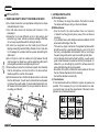
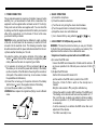
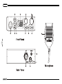
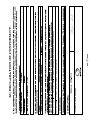
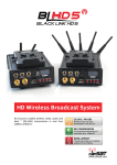
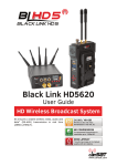
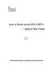
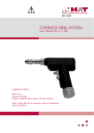
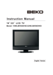
Downloaded from www.cbradio.nl
WARNING
Please install the antenna (connect to the location “B” on the back panel of the radio) and set the SWR (Standing Wave
Ratio) before transmitting. Failure to do so may result in destruction of the power amplifier, which is not covered by the
guarantee.
WELCOME TO USE
310M is a Multi-norms and multi-function CB radio which provides you with top performance.
With the use of SMT technology to guarantee the best stability, reliability and unprecedented quality, 310M is a new step
in personal communication and is surely the best choice for professional users of CB radios. Moreover, it adopts flash
CPU in the radio, which makes 310M ready for future upgrading and functions expanding.To ensure that you use the radio
to the fullest, please read this manual carefully before installing.
RESET
-Hold key (7) [ CH9/19 ] to power on, the radio will reset, all channel data will resume factory default setting.
CONTENTS
INSTALLATION ..................................................................................................................................................................................1
WHERE AND HOW TO MOUNT YOUR MOBILE CB RADIO ..................................................................................................................1
ANTENNA INSTALLATION .................................................................................................................................................................1
POWER CONNECTION.....................................................................................................................................................................2
BASIC OPERATIONS ........................................................................................................................................................................2
ADJUSTMENT OF SWR(standing wave ratio) ......................................................................................................................................2
HOW TO USE YOUR CB RADIO ......................................................................................................................................................4
ON/OFF-VOLUME ............................................................................................................................................................................4
MANUAL SQUELCH .........................................................................................................................................................................4
AUTOMATIC SQUELCH ....................................................................................................................................................................4
CHANNEL SELECTION .....................................................................................................................................................................4
MODULATION MODE SELECTION ....................................................................................................................................................4
NORM SELECTION ..........................................................................................................................................................................4
AUTOMATIC SCANNING ...................................................................................................................................................................4
PRIORITY CHANNEL9/19..................................................................................................................................................................5
TRANSMITTING ...............................................................................................................................................................................5
EXTERNAL SPEAKER JACK .............................................................................................................................................................5
EC declaration ..................................................................................................................................................................................6
TECHNICAL CHARACTERISTICS ...................................................................................................................................................7
INSTALLATION
2. ANTENNA INSTALLATION
1. WHERE AND HOW TO MOUNT YOUR MOBILE CB RADIO
1
a)You should choose the most appropriate setting from a simple
and practical point of view
b)Your CB radio should not interfere with the driver or the
passengers.
c)Remember to provide different wires for the passing and
protection (e.g. power, antenna, accessory cabling) so that they
do not in any way interfere with the driving of vehicles.
d)To install your equipment, use the cradle (H) and the selftapping screws [E] provided (drilling diameter 4 mm). Take care
not to damage the vehicle’s electrical system while drilling the
dash board.
e)Do not forget to insert the rubber joints [G] between the CB
and its support as these have a shock-absorbing effect which
permits gentle orientation and tightening of the set.
f)Choose where to place the microphone support and remember
that the microphone cord must stretch to the driver without
interfering with the controls of the vehicle.
G)As the transceiver has a frontal microphone socket, it can be set
into the dash board. You will need to add external loud speaker
to improve the sound quality of communications(connector ext.
SP situated on the back panel: D). Ask your dealer for advice on
mounting your CB radio.
E
E
E
E
H
G
G
CH
H
F
F
CH
a) )Choosing antenna:
- For CB radios, the longer the antenna, the better its results.
Your dealer will help you with your choice of antenna.
b) Mobile antenna:
- Must be fixed to the vehicle where there is a maximum
of metallic surface(ground plane), away from windscreen
mountings.
- If you already have a radio-telephone antenna installed, the CB
antenna should be higher than this.
- There are two types of antenna: Pre-regulated antenna which
should be used on a good ground plane (e.g. car roof or lid of
the boot), and adjustable antenna which offer a much larger
frequency range and can be used on a smaller ground plane.
- For an antenna which must be fixed by drilling, you will need a
good contact between the antenna and the ground plane. To
obtain this, you should lightly scratch the surface where the
screw and tightening star are to be placed.
- Be careful not to pinch or flatten the coaxial cable (as this runs
the risk of break down and/or short circuiting).
- Connect the antenna to location (B).
c) Fixed antenna:
A fixed antenna should be installed in a space as spacious as
possible. If it is necessary for you to fix the antenna to a mast,
you need to keep it as per the requirements of the laws in force
(please turn to professional advice).
D
B
C
OUTPUT RADIUS PATTERNS
1. POWER CONNECTION
This is protected against an inversion of polarities. However, before
switching it on, you are advised to check all the connections. Your
equipment must be supplied with a continued current of 12 volts (A).
Today, most cars and lorries are negative earth. You can check this
by making sure that the negative terminal of the battery is connected
either to the engine block or to the chassis. If this is not the case,
you should consult your dealer.
WARNING: Lorries generally have two batteries to supply a voltage
of 24 volts, in which case it will be necessary to insert a 24/12 volt
converter into the electrical circuit. The following connection steps
should be carried out with the power cable disconnected from the set.
a)Check whether the battery is of 12 volts.
b) Locate the positive and negative terminals of the battery ( is
red and is black). Should it be necessary to lengthen the power
cable, please use the same or a superior type of cable.
c) It is necessary to connect your CB to a permanent ( ) and ( ).
We advise you to connect the power cable directly to the battery
(as the connection of the CB cable to the wiring of the car-radio or
other parts of the electrical circuit may, in some cases, increase
the possibilities of interference).
d) Connect the red wire ( ) to the positive terminal of the battery
and the black ( ) wire to the negative terminal of the battery.
e) Connect the power cable to your CB radio.
WARNING:Never replace the original fuse (5A) by one of a different
value.
2. BASIC OPERATIONS
a) Connect the microphone
b) Check the antenna connections
c) Turn the set on by turning the volume knob clockwise
d) Turn the squelch knob to minimum (Full-anti clockwise)
e) Adjust the volume to a comfortable level
f ) Go to channel 20 E by using either the [
] or [
] key.
3. ADJUSTMENT OF SWR(standing wave ratio)
WARNING: This must be carried out when you use your CB radio
for the first time (and whenever you re-position your antenna). The
adjustment must be carried out in an obstacle-free area.
*Adjustment should be operated with external SWR meter.
a)To connect the SWR meter
Connect the SWR meter between the CB radio and the antenna
as close as possible to the CB radio (use a maximum of 40cm 2
cable)
b) To adjust the SWR meter
-Set the CB to channel 20 E band in FM
-put the switch on the SWR meter to position CAL or FWD
-Press the <<Push-To-Talk>> switch on the microphone to
transmit
-Bring the index needle to ▼ by using the calibration key
- Change the switch to position SWR (reading of the SWR level)
The reading on the meter should be as near as possible to 1. If
this is not the case, re-adjust your antenna to obtain a reading
as close as possible to 1.( An SWR reading between 1 and 1.8
is acceptable).
- It will be necessary to re-calibrate the SWR meter after each
adjustment of the antenna.
Your CB is now ready for use.
3
HOW TO USE YOUR CB RADIO
1. ON/OFF-Volume
a)To turn the set on, turn the knob (1) clockwise.
b)To increase the sound level, turn the same knob further clockwise.
2. Manual Squelch
Turn the SQ knob (2) clockwise to the exact point where all
background noise disappears. Please note that this control is
fine regulation, if you set this SQ control to the maximum (fully
clockwise), the radio can only receive the strongest signal.
3. Automatic Squelch
The automatic squelch (ASQ ) uses a preset average value. It can
be activated by short key (5) [ ASQ ], The automatic squelch mode
(AQ icon) is indicated on the LCD.
4. Channel selection
All channels can be selected by channel selector keys (8) [
] or (9) [
].The selected channel is displayed on the LCD. In
communication both transceivers (the receiving and transmitting party)
need to be in the same channel and under same modulation type.
5. Modulation MODE selection
This key (6) [AM/FM] allows selecting the AM or FM modulation.
Your modulation mode has to correspond to the one of your
correspondent.
With the version Full Multi Norm in the norm UK, you can switch
between the E.band and the UK band, which is indicated by
symbol "E" or "UK", by pressing the key (6) [AM/FM].
The CB band E consists of the 40 CEPT channels. The CB
band UK consists of 40 channels starting from 27.60125 MHz to
27.99125 MHz.
6. Norm Selection
The version Full Multi Norm can be set by the user to the following
norms:
D 80 FM (26.565 - 27.405 MHz), 4 W
40 AM (26.965 - 27.405 MHz), 1W.
EU 40 FM (26.965 - 27.405 MHz), 4 W
40 AM (26.965 - 27.405 MHz), 1W.
EC 40 FM (26.965 - 27.405 MHz), 4 W.
UK 40 FM (27.60125 - 27.99125 MHz), 4 W
40 FM (26.965 - 27.405 MHz), 4W.
PL 40 FM (26.960 - 27.400 MHz), 4 W
40 AM (26.960 - 27.400 MHz), 4W.
E 40 FM (26.965 - 27.405 MHz), 4 W
40 AM (26.965 - 27.405 MHz), 4W.
US 40 AM (26.965 - 27.405 MHz), 4W.
NZ 40 FM (26.330 - 26.770 MHz), 4 W
40 AM (26.330 - 26.770 MHz), 4W.
4
To change current norm, please hold the key (6) [AM/FM ] while
turning the radio on. In the display, the symbol of the current norm
appears, please select the norm by pressing the channel selector
key(8) [
] or (9) [
]. To verify your selection, turn the
radio off and on again, the radio automatically returns to the
selected operation mode.
Note: The E norm is internally set to 40 channels FM+AM, 4
Watts only.
7. Automatic Scanning
Press the key (10) [SC] to enable the SCAN function. Before
enabling the SCAN function, firstly turn the SQ control clockwise
till the background noise is cut out. Then press the key (10) [SC],
radio will automatically scan all channels and the SC icon will
appear on the LCD.
When a signal is detected on a channel, scanning stops on this
channel. You can receive the calling, and also, can transmit on
this channel by pressing PTT key. If there is no transmission or
detected signal on that channel within 5 seconds, radio will start
scanning again. To exit the SCAN function, press the SC Key or the
PTT key.
8. Priority Channel 9 / 19
- It the contains the priority channels 9 and 19. Priority channel 9
is selected by pressing the key (7) [ CH9/19 ] once. To set priority
channel 19, press the key (7) [ CH9/19 ] twice.
9. Transmitting
5
To transmit, press and hold the key(A) [ PTT ] at the microphone
and the TX icon will appear on the LCD.
For best quality, please speak normally at a distance of 2 - 4
inches. Speaking too loudly will cause distortions and make the
signal difficult to understand.
On completion of the transmission release the PTT key and the
radio will revert to receiving mode.
10. External speaker jack
The radio is equipped with a 3.5 mm jack socket (D) at the rear
panel to connect an external.speaker of 4 - 8 Ohm impedance.
At 4 Ohm the speaker load can be 4 watts. When the external
speaker is connected, the internal speaker will be switched off.
6
TECHNICAL CHARACTERISTICS
Modulation modes
Frequency ranges
Antenna impedance
Power supply
Dimensions(in mm)
Weight
7
Frepuency error
Carrier power
Transmission interference
Audio response
Emitted power in the adj.channel
Microphone sensitivity
Maximum current
Modulated singal distortion
Max sensitivity at 20dB sinad
Frequency response
Adjacent channel selectivity
Maximum audio power
Squelch sensitivity
Maximum current
GENERAL
AM/FM
26.965---27.405MHz
50 Ohms
13.2V
150×140×41mm
761G
TRANSMISSION
+/- 300HZ
1W/4W
inferior to 4nW(-54dBm)
300HZ to 3KHZ in AM/FM
inferior to 20uW
3mV
max 3A
inferior to 5%
RECEPTION
0.8uV -113 dBm FM
1.5uV -103 dBm AM
300HZ to 3KHZ in AM/FM
60dB
3W
Minimum 0.2uv -120 dBm
Maximum 1mV -47 dBm
0.3A nominal/1.2A maximum