1
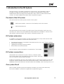
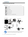
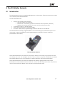
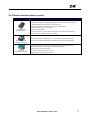
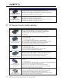
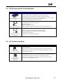
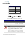
TM
Modular
powerchair control system
DX PRODUCT SELECTION GUIDE
TM
1 Introduction to the DX System
The DX-system is a modular powerchair control system. This modularity makes it
possible to design a powerchair that can meet the requirements of any user requirements that can range from simple drive-only control to full environmental
control. Just add additional modules when requirements grow.
The heart of the DX System
The most basic DX control system consists of two parts:
A DX Power Module, connects to the battery and to the motors
A DX Master Remote
The Master Remote is the brain of the DX System. Every DX System must have one,
and only one. There are several different Master Remotes available to choose from:
with joystick, without joystick, chin remote, attendant remote, etc.
DX System extensions
In addition to the Power Module and the Master Remote, many other remotes and
modules are available to extend the DX System, like:
•
•
•
•
Secondary Remotes, for example: attendant remotes, sip ‘n puff, finger steering
Switch input modules
Lighting and Seating control modules
Environmental control modules
The DX System can be extended to a maximum of 16 modules.
DX System connections
All modules are connected to each other by a DX BUS cable.
Most DX Modules have two DX BUS connector sockets. That way
you can connect another DX part easily.
DX BUS is an interface (the way the modules "talk" to each other) based on the CAN
interface, which is widely used in the automotive industry. CAN is well known for its
reliability and its fault detection. DX BUS inherits this reliability, and even improves on it.
One system fits all
Start out with a simple system and add the modules you need at the time they
become available, or when the application requirements grow.
www.dynamiccontrols.com
3
2 A typical DX powerchair setup
A standard powerchair installation with the DX System consists of the following
electrical parts:
The Batteries
The Motors
P
The Parkbrakes
A DX Power Module
A DX Master Remote
The DX BUS cables
Optional: Actuator or Lighting Modules
DX Power Module
P
PB1
24V Battery
DX Master Remote
M1
M2
P
To Battery
Charger
DX BUS
PB2
To HHP
or Wizard
Do not install, maintain, or operate this equipment before you have read
and understood the installation manuals for the product. Follow the
instructions of the manuals, otherwise injury or damage can result.
4
DX Product Selection Guide, October 2007
TM
2.1 DX BUS Module connection layout
DX Modules normally have one or two DX BUS sockets for system interconnections.
Smaller DX Modules can have a fixed cable that ends in a DX BUS plug, instead of DX
sockets.
The optimum connection layout is dependent on the type of modules that are
present in the DX System. Low-current modules can be connected in series. This
provides a low-cost and simple solution.
DX BUS
24V
DX
Power
Module
DX Master Remote
DX BUS
DX
module
DX
module
DX
module
DX
module
DX modules connected in series
Because of the internal resistance of the DX BUS cable, high-current modules can
cause a voltage drop on the DX BUS when they are connected far away from the
Power Module. For this reason all high-current DX Modules (for example actuators
and lights) must be connected as close to the Power Module as possible, preferably
in parallel.
DX BUS
24V
DX
power
module
DX Remote
DX BUS
DX
module
HIGH I
DX
module
HIGH I
DX splitter box
DX-SKT-X4
DX
module
HIGH I
DX
module
LOW I
DX
module
LOW I
High-current DX modules connected in parallel
Note:
The total length of all DX BUS cables together must not exceed 15 m.
www.dynamiccontrols.com
5
3 The DX Power Module
The DX Power Module converts the speed and direction signals generated by a DX Remote
into high current outputs. These outputs drive the motors and activate the parkbrakes.
The Power Module must be connected to:
•
•
•
•
The DX BUS
The battery
The motors
The parkbrakes
M/PB-2
Battery
DX BUS
M/PB-1
The Power Module is fully programmable for a wide range of powerchair types and user
needs.
3.1 Available Power Modules
Power Module
Current
Motor type
60A dual
24V DC
80A dual
24V DC
120A single (2x 60A parallel)
24V DC
160A single (2x 80A parallel)
24V DC
DX-PMB
DX-PMB2
DX-PMB-S
DX-PMB2-S
The PMB-S has its two motor and Park Brake channels driven in parallel, for a single motor
output with twice the current of each channel of a standard Power Module. The PMB-S is
used in DX Systems with only one drive motor, such as servo steered powerchair systems.
6
DX Product Selection Guide, October 2007
TM
4 The DX Master Remote
4.1 Introduction
The Master Remote is the central building block in a DX System. Every DX System must have
one, and only one Master Remote.
The DX Master Remote
•
•
•
•
Acts as the primary user interface
o Has the system on/off switch
o Reads user commands (joystick movement, button pushes, switches)
o Displays the system status to the user via the System Status LED
Controls the status of the DX System
Stores and controls up to six Drive Profiles.
Provides a DX System programming socket for the HHP or the Wizard.
The Master Remote is fully programmable to suit a wide range of powerchair types and
user needs. Correct installation and programming are essential to ensure optimum
performance and safety.
The G90 Master Remote
Most Master Remotes have their own user input device in the form of a joystick, but this is
not always the case. For example: the G91 does not have a joystick, it depends on either a
Secondary Remote or a set of switches to obtain direction and speed commands.
Most Master Remotes have their own display with battery gauge and system status
information. Some Master Remotes however, such as the chin remote and the tray remote,
do not have their own display, they only have a System Status LED.
www.dynamiccontrols.com
7
4.2 Available Master Remotes
4.2.1 Master Remotes with joystick
Master Remote
DX-REMG90A
DX-REMG90T
DX-REM34
Dolphin Remote
DX-REM41
DX-REM41S
Dolphin Tray Remote
DX-REM32
Chin Remote
DX-REM35
Tray Remote
DX-ACU3
Attendant Control Unit
8
Application
Advanced driving
Advanced seating
Highly customisable
Switched control available
Joystick only menu control available
Environmental control
G90A : two sockets to connect external switches
G90T : two toggle switches
Advanced Driving
Seating and lighting
All actuators directly accessible from keypad
Advanced Driving
Seating and lighting
All actuators directly accessible from keypad
Chin control
Drive only: Joystick, on/off switch, Speedpot
No display
No battery charger socket, only a programming socket
Drive only: Joystick, on/off switch, Speedpot
No display
No battery charger socket, only a programming socket
Master Remote joystick for attendant use.
Switch to take control / release control
Can control chair, charging and actuators.
Optionally use Secondary Remote for user control.
DX Product Selection Guide, October 2007
TM
4.2.2 Master Remotes without joystick
Master Remote
DX-REMG91
DX-REMG91S
DX-MASTERSW
Switch Interface
DX-SCR
Specialty Controls
Application
Can be mounted close to the face of the user to optimise visibility
Advanced driving, seating, lighting and environmental control
3-quadrant RIM, switched or proportional
Optional joystick control with Secondary Remote
Bi-directional actuator control
Highly customisable
Accessory Shortcut Key gives access to the last used function
G91S provides single switch scanning
Switched Drive (4 directions) + one switched On/Off control
Optional joystick/attendant control with Secondary Remote
Advanced menu-driven driving and environmental control
Joystick operation through Secondary Remote
Joystick-only control option
Joystick + Mode button control
Single Switch Scanning control
www.dynamiccontrols.com
9
5 DX Modules
5.1 Introduction
Including the Power Module and the Master Remote, a DX System can contain up to 16 DX
compatible modules depending on the application.
Available types of DX Modules are
•
•
•
•
•
•
•
Remote Joystick Module (RJM),
o DX-RJM Secondary Remotes
o Switch modules
Attendant Control Unit (ACU), joystick with attendant switch and Speed Pot
o DX-ACU1
Actuator Remote Control (ARC), 5 channels of extend/retract switches
o DX-ARC / DX-ARC-SWB
Servo Steering Motor Modules
o DX-SLM, for steering servo motor control + lights
Lighting Modules
o DX-SLM/ DX-LM/ DX-CLAM
Actuator Modules
o DX-CLAM/ DX-TAM
Environmental Control Unit Modules (ECU)
o DX-ECU
The DX System has the option to declare some DX Modules as safety critical. This makes
sure that the DX System will not operate when that particular module is not detected
during power-up.
Warning:
Each DX Module has its own Installation Manual that describes the
installation requirements of that particular module. If you have
purchased a specific DX Module, read and understand the installation
manual of that module before installing or using the module.
10
DX Product Selection Guide, October 2007
TM
5.2 Secondary Remotes
A Secondary Remote is a secondary user input device, for example an attendant joystick.
A Secondary Remote…
• Converts user input (the joystick or the switches, depending on the type of
Secondary Remote) to speed and direction signals
• Sends the speed and direction signals to the Master Remote via the DX BUS
• Can control non-driving functions (for example actuators or environmental
controls), if the Master Remote in use supports joystick control of these functions.
To use a Secondary Remote, select it as the Joystick Source in one of the Drive Profiles.
Only one RJM-type Secondary Remote can be present in a DX System at the same time.
5.2.1 Available Secondary Remotes
Secondary Remote
DX-RJM
Remote Joystick
Module
DX-RJM-HD
Heavy Duty Joystick
DX-RJM-MINI
DX Mini Joystick
DX-ACU1
Dual Control
DX-RJM-VIC-CCD
Finger Steering Control
DX-ACC4 (RJM-type)
Four Switch Interface
Applications
Attendant joystick
User joystick for Master Remotes without joystick
User joystick mountable on the armrest or away from it
Compact chin remote
Users without finer hand movement
Situations where a normal joystick can be damaged
Full proportional control with very little movement or force
Completely sealed - can be used as a tongue joystick
Attendant joystick
Attendant can take drive control with Attendant/User switch
Attendant can adjust chair speed
ACU-type Secondary Remote - can be used together
with an RJM-type Secondary Remote
Zero force optical operation
Users with very little strength in their hand/fingers
Full proportional control
Finger movement of 2 mm per direction is enough
Driven by four momentary switches,
Either separate switches or
Switches combined in one unit (for example the wafer switch)
Provides up to eight driving directions
www.dynamiccontrols.com
11
Secondary Remote
Applications
DX-5SW (RJM-type)
5 Switch Module
Five switch inputs plus extra 'Emergency Stop' input
Accepts input devices terminated in a '9-pin D' connector
Analog Latch mode gives infinitely adjustable cruise speed
3 momentary modes, 4 latched modes
DX-SNP (RJM-type)
Sip and Puff Module
Recognises soft and hard sips and puffs
Sip and puff pressures programmable
Analog Latch mode gives infinitely adjustable cruise speed
3 momentary modes, 4 latched modes
5.3 DX Steering/Actuator/Lighting Modules
DX Module
DX-SLM
Servo Lighting Module
DX-CLAMB
Combined Lighting and
Actuator Module
DX-LM-Z
Lighting Module
DX-TAM
Two Actuator Module
DX-ARC5
Actuator Remote
Control
DX-ARC-SWB
ARC Switchbox
12
Function / Applications
Drives a separate motor for steering castor wheels
Commonly used for high speed outdoor powerchairs
24V, 30A peak, 5A continuous Servo steering
24V lighting
Compact module to connect all common functions:
• Five actuators
• Front lights, Rear lights
• Left and right turning indicators, Hazard lights
All power and control signals provided through the DX BUS
Soft Start feature provides smooth actuator control
Slow/Stop input (for actuator position switches)
24V lighting (DX-LM-Z)
• Front lights, Rear lights
• Left and right turning indicators, Hazard lights
Short-circuit and open-circuit detection
Simple and compact solution for two actuator control
All power and control signals provided through the DX BUS
Soft Start feature provides smooth actuator control
Slow/Stop input (for actuator position switches)
Programmable current limits and maximum operation time
Separate handset for actuator control
Ideal for
• attendant use
• users who have difficulty with the controls of the Master Remote
Controls up to 5 seat positioning actuators
Actuators can optionally be operated while driving
Can be programmed to control horn, lights and driving
Needs DX-CLAMB or DX-TAM to operate
Controls up to 5 seat positioning actuators
Can be programmed to control horn, lights and driving
Operates with external switches (DB15 connector)
Choose switch combinations and mounting positions freely
One extra 24V/1A power supply output
DX Product Selection Guide, October 2007
TM
5.4 DX Environmental Control Modules
DX Module
Function / Applications
DX-ECU
Environmental Control
Unit
Needs the DX-SCR, the G90 or the G91 Remotes to operate
Uses the Secondary driving Remote as input control
'8 Output mode' controls up to eight separate devices
'Mouse mode' acts as a mouse mover, fifth switch acts as click
Up to two DX-ECU modules in one DX System
All outputs are isolated relay contacts
DX-IRIS2
Infra-Red Transmitter
DX-PCMR
Infra-Red Mouse
Receiver
Learning infra-red remote control
360° transmission
Supports GEWA devices
Works together with the Specialty Controls Master Remote
Receives mouse commands from the DX-IRIS2
Works alongside the computer's existing mouse
Serial port connection
USB-Serial converter: DX-USB-COM
5.5 DX Auxiliary Modules
DX Module
DX-ACC2
Drive Stop Module
DX-ACC3
Charger Socket
Module
Function / Applications
Powerchair lock
Makes sure that only authorised people can drive the chair
Lighting and actuator functions are still operational when the
powerchair is locked
Small charger socket, can be mounted in a convenient location
Use with remotes that do not have a charger socket
Use as an alternative to the Master Remote charger socket
Maximum 8 A charging current
www.dynamiccontrols.com
13
6 The DX BUS cable
Cable specifications – straight cable
DX BUS cable straight
Length
Part/Order number
300 mm
1 ft
GSM63003
500 mm
1' 8"
GSM63005
1.0 m
3' 3"
GSM63010
1.5 m
4' 11"
GSM63015
2.0 m
6' 7"
GSM63020
2.5 m
8' 2"
GSM63025
DX BUS cable with Ferrite bead to improve EMC
2.0 m
6' 7"
GSM63020F
DX BUS extension cable (male + female plug)
300 mm
1 ft
GSM65433
1.0 m
3' 3"
GSM63081
35
B
R-
13 x 16
Ø7.0
YY x 100 ± 10
D
EN
The part number of the straight cable is GSM630YY, where YY = the length in 100 mm.
Parameter
Connector Latch Holding Force
Cable Strain
Cable Flex Force
Minimum Cable Bend Radius
Flexing values for (T > –10°C/14°F)
Operating Temperature
(ambient, fixed installation)
Cable Temperature Rating
Value
40 N min
100 N max (accidental, non-repetitive)
10 N max
10 mm / 0.39 inch - fixed installation
25 mm / 1 inch
- occasional flexing
50 mm / 2 inch
- frequent flexing
–25°C to +50°C
–13°F to +122°F
80°C / 176°F (internal operating temp)
Warnings:
1. The specified bend/flex radiuses are minimum values and must be
considered as a guideline only. Where frequent flexing is part of the
intended application, the installer must ensure an appropriate
bend/flex radius for the intended and foreseeable environmental
conditions.
2. Extreme cold temperatures considerably reduce cable flexibility.
Appropriate life testing must be carried out to determine/confirm the
expected service life and inspection and maintenance schedule.
14
DX Product Selection Guide, October 2007
TM
Cable specifications – curly cable
DX BUS Curly Cable
Coil Length
Tail Length Lb
300 mm / 1 ft
200 mm / 8 inch
300 mm / 1 ft
200 mm / 8 inch
Tail Length La
200 mm / 8 inch
500 mm / 1'8"
Part/Order number
GSM63051
GSM63052
Ø26 ± 2
La ± 20
40
300 ± 30 approx. 40 coils
compressed coil length
Ø7.5
13 x 16
D
EN
-B
R
Lb ± 20
Parameter
Connector Latch Holding Force
Cable Strain
Spring Force extension refers to the coiled section
Minimum Cable Bend Radius
Flexing values for (T > –10°C/14°F)
Operating Temperature
(ambient, fixed installation)
Cable Temperature Rating
Value
40 N min
100 N max (accidental, non-repetitive)
< 20N @ 2x extension (T > 10°C/50°F)
< 50N @ 2x extension (T > –10°C/14°F)
< 30N @ 3x extension (T > 10°C/50°F)
20 mm / 0.8 inch - fixed installation
30 mm / 1.2 inch - occasional flexing
50 mm / 2 inch
- frequent flexing
–25°C to +50°C
–13°F to +122°F
80°C / 176°F (internal operating temp)
Warnings:
1. Do not extend the coils when the temperature is below 0°C/32°F.
Do not extend the coils farther than 2x compressed length when the
temperature is below 10°C/50°F.
Avoid extension above 3x compressed length at all times. This may
result in permanent stretching of the coils.
2. Make sure that the spring force is not applied to the DX BUS connector.
Fasten a strain relief or cable tie on or near to the coiled section of the
cable.
www.dynamiccontrols.com
15
TM
Contact Details
Dynamic has a global network of sales and service centres. Please contact your nearest
Dynamic representative for Sales and/or Service advice, or visit our web site:
www.dynamiccontrols.com
New Zealand – Head Office
Australia – Service Agent
Dynamic Controls
17 Print Place
Ph: +64 3 962 2519
PO Box 1866
Fax: +64 3 962 2966
Christchurch
New Zealand
E-mail: [email protected]
Electronic Mobile Service
46 Berripa Close
Ph: +61 2 9887 2824
North Ryde
Fax: +61 2 9887 2114
Sydney, NSW
Australia 2113
E-mail: [email protected]
Europe – Sales & Service
Asia – Sales
Dynamic Europe Ltd.
Stonebridge Cross Business Park
Droitwich, Worcestershire
WR9 0LW
United Kingdom
Dynamic Controls Ltd. Asia
Floor 4-3, No. 59
Ph: +886 955 335 243
Tien Hsiang Rd
Fax: +886 943 837 402
Chung Shan District
Taipei 104
Taiwan R.O.C.
E-mail: [email protected]
Ph: +44 1905 772 321
Fax: +44 1905 827 520
E-mail: [email protected]
North America – Sales & Service
Dynamic North America
31335 Industrial Pkwy
Ph: +1 440 979 0657
Suite 2
Fax: +1 440 979 1028
North Olmsted, OH 44070
USA
E-mail: [email protected]
DX Product Selection Guide, October 2007