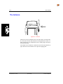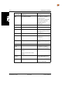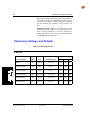
1
The LXE 2325 is obsolete. Revision C contains system configuration instruction for
2325's shipped with an abbreviated version of ROM-DOS. System configuration
instructions for the expanded version of ROM-DOS begin with Revision D. Please
contact your LXE customer support representative for assistance.
2325
Reference Guide
2325A137REFGD
March 2000
E-EQ-2325RG-C-ARC
Copyright © 2000 by LXE Inc.
An EMS Technologies Company
All Rights Reserved
2
3
R
2
5
E
A
V
1
I
3
S
7
I
R
O
E
N
F
G
B
D
Regulatory Notices
Notice:
LXE Inc. reserves the right to make improvements or changes in the products described in this
manual at any time without notice. While reasonable efforts have been made in the preparation of
this document to assure its accuracy, LXE assumes no liability resulting from any errors or
omissions in this document, or from the use of the information contained herein.
Copyright Notice:
This manual is copyrighted. All rights are reserved. This document may not, in whole or in part,
be copied, photocopied, reproduced, translated or reduced to any electronic medium or machinereadable form without prior consent, in writing, from LXE Inc.
Copyright © 2000 by LXE Inc., An EMS Technologies Company
125 Technology Parkway, Norcross, GA 30092, U.S.A. (770) 447-4224
LXE is a registered trademark of LXE Inc. All other brand or product names are trademarks or
registered trademarks of their respective companies or organizations.
Note: The original equipment’s Reference Manual is copyrighted by Percon® Inc. This manual
has been amended by LXE® Inc., for the 2325 and Docking Stations with Percon’s express
permission.
Notice:
The long term characteristics or the possible physiological effects of radio frequency
electromagnetic fields have not been investigated by UL.
FCC Information:
This device complies with FCC Rules, part 15. Operation is subject to the following conditions:
1. This device may not cause harmful interference
and
2. This device must accept any interference that may be received, including interference that
may cause undesired operation.
Note: This equipment has been tested and found to comply with the limits for a Class A digital
device, pursuant to part 15 of the FCC rules. These limits are designed to provide reasonable
protection against harmful interference when the equipment is operated in a commercial
environment. This equipment generates, uses, and can radiate radio frequency energy and, if not
installed and used in accordance with the instruction manual, may cause harmful interference to
radio communications. Operation of this equipment in a residential area is likely to cause
harmful interference in which case the user will be required to correct the interference at his own
expense.
Warning: Changes or modifications to this device not expressly approved by LXE, Inc., could
void the user’s authority to operate this equipment.
Shielded cables must be used with this unit to ensure compliance with the FCC Class A limits.
Docking Cradles Product Label Statement
This device complies with part 15 of the FCC Rules. Operation is subject to the following two
conditions: (1) This device may not cause harmful interference, and (2) this device must accept
any interference received, including interference that may cause undesired operation.
EMC Directive Requirements:
This is a Class A product. In a domestic environment this product may cause radio interference in which
case the user may be required to take adequate measures.
Industry Canada:
This Class A digital apparatus meets all requirements of the Canadian Interference Causing Equipment
Regulations. Operation is subject to the following two conditions: (1) this device may not cause harmful
interference, and (2) this device must accept any interference received, including interference that may
cause undesired operation.
Approvals:
EMI / EMC Standards:
FCC Part 15 Subpart B
EN 50022 Class A
EN50082-1
Transceiver:
FCC Part 15, Subpart C
ETSI 300 328
IC-RSS 210
Safety Standards:
EN 60825-1
CDRH Class 2
Revision Notice
2325 Reference Guide
Upgrade from Revision A to Revision B
The revision B upgrade to this manual contains changes made to the following sections:
Section
Action
Entire Manual
Replace the word "terminal" with "computer."
Chapter 1 - Introduction and
Specifications
Replace "Contacting LXE" with revised text.
Chapter 2 - Using Advanced
Features
Add "Troubleshooting - Enable I 2 of 5." Add new sections: "Proxim
Configuration Settings" and "Lucent Configuration Settings."
Chapter 3 - Software
Configuration
Add section titled "Terminal Emulation."
Chapter 4 - The
Configuration Utility
Replace Figure 4-14, 4-16, and 4-18. Add new 4-19.
Chapter 7 - The Docking
Stations
Add non-rechargeable battery warning graphic and text. Add section titled
"Vehicle Mounted DC Single Dock."
Appendix B - Programming
Parameters
Remove section titled "Terminal Emulation in a 2.4GHz Radio System."
Add two new configuration parameters – Ames Enable and Spotting Beam
Enable.
Table of Contents
CHAPTER 1 INTRODUCTION AND SPECIFICATIONS
1-1
Introduction .................................................................................................1-1
Document Conventions ...........................................................................................1-2
Technical Specifications ..............................................................................1-3
General ....................................................................................................................1-3
Physical ...................................................................................................................1-3
Keyboard .................................................................................................................1-4
Display.....................................................................................................................1-4
Battery .....................................................................................................................1-5
Power Management .................................................................................................1-6
Memory ...................................................................................................................1-6
Laser Module...........................................................................................................1-7
Radio PC Card.........................................................................................................1-8
PC Card ...................................................................................................................1-9
Serial/Accessory....................................................................................................1-10
Contacting LXE .........................................................................................1-11
Manuals and Accessories ......................................................................................1-13
CHAPTER 2 USING ADVANCED FEATURES
2-1
Introduction .................................................................................................2-1
Changing the Laser Module’s Orientation....................................................2-1
Programming the Laser Triggers.................................................................2-2
Resetting the 2325 ......................................................................................2-3
Warm Boot ..............................................................................................................2-3
Cold Boot ................................................................................................................2-3
Safe Boot .................................................................................................................2-4
Hardware Reset .......................................................................................................2-5
Using PC Cards...........................................................................................2-6
Opening the PC Card Slot Cover ............................................................................2-6
Inserting a PC Card .................................................................................................2-7
Card Recognition and Configuration ......................................................................2-8
Radio Card Antenna Connector ..............................................................................2-9
Radio Card Antenna Ports.......................................................................................2-9
Removing a PC Card .............................................................................................2-10
The Serial Port ..........................................................................................2-11
2325A137REFGD
Revision B
2325 Reference Guide
ii
Table of Contents
The Scanner Port ......................................................................................2-11
The Antenna..............................................................................................2-12
The Disk Drives .........................................................................................2-13
Additional Drives ..................................................................................................2-13
Configuring the 2325 .................................................................................2-14
Troubleshooting - Enable I 2 of 5..........................................................................2-14
Transferring Files ......................................................................................2-15
Advanced Power Management..................................................................2-18
Batteries.................................................................................................................2-18
Doze Mode ............................................................................................................2-18
Auto-Off Timer .....................................................................................................2-18
Backlight................................................................................................................2-18
Power Management at the Radio Card..................................................................2-19
Radio PC Card Configuration ....................................................................2-20
Getting Started.......................................................................................................2-20
Installing ODI Drivers ...........................................................................................2-20
Installing NDIS Drivers.........................................................................................2-27
Proxim Configuration Settings ..............................................................................2-30
Lucent Configuration Settings...............................................................................2-34
RF Throughput, Performance and Troubleshooting...................................2-38
Power Management at the Proxim RangeLAN2 Access Point .............................2-38
Site Survey.............................................................................................................2-39
Throughput and Performance ................................................................................2-40
Operational Problems ............................................................................................2-40
Problems with DOS Drivers..................................................................................2-42
CHAPTER 3 SOFTWARE CONFIGURATION
3-1
Introduction..................................................................................................3-1
BIOS and DOS ........................................................................................................3-1
PC Card and RF Networking Software ...................................................................3-1
Disk Drives and Files ...................................................................................3-2
Drive A ....................................................................................................................3-3
Drive B ....................................................................................................................3-5
Drive C ....................................................................................................................3-8
Drive D ..................................................................................................................3-10
Drive E...................................................................................................................3-10
System Configurations ..............................................................................3-11
Default Configuration............................................................................................3-11
I/O PC Card Support Configuration ......................................................................3-13
2325 Reference Guide
Revision B
2325A137REFGD
Table of Contents
iii
Data Entry .................................................................................................3-14
Keyboard Data Entry.............................................................................................3-14
Barcode Data Entry ...............................................................................................3-14
RS-232 Data Entry ................................................................................................3-14
Terminal Emulation...............................................................................................3-15
CHAPTER 4 THE CONFIGURATION UTILITY
4-1
Introduction .................................................................................................4-1
Installing and Starting the Utility on a PC.....................................................4-1
BIOS Upgrade File Location...................................................................................4-2
RF Files Location ....................................................................................................4-2
Quick Start ..................................................................................................4-5
The Main Menu............................................................................................4-7
Default.........................................................................................................4-9
The Custom Configuration Menu...............................................................4-10
The File Configuration Windows..........................................................................4-15
The Program Settings Windows............................................................................4-25
The Comm Settings Dialog Box.................................................................4-33
Comm Port.............................................................................................................4-33
Baud Rate ..............................................................................................................4-33
The File Transfer Window .........................................................................4-34
List File .................................................................................................................4-34
Save .......................................................................................................................4-35
Browse...................................................................................................................4-35
Files to Transfer ....................................................................................................4-36
Add ........................................................................................................................4-36
Browse...................................................................................................................4-37
Edit ........................................................................................................................4-37
Delete ....................................................................................................................4-37
Receive ..................................................................................................................4-38
Send .......................................................................................................................4-39
Done ......................................................................................................................4-39
CHAPTER 5 USING XFER
5-1
Introduction .................................................................................................5-1
About XFER ................................................................................................5-1
Syntax and Parameters ...............................................................................5-2
XFER Parameters ....................................................................................................5-2
2325A137REFGD
Revision B
2325 Reference Guide
iv
Table of Contents
The XFER_ARGS Environment Variable...................................................5-21
Multiple-Option Blocks ...............................................................................5-23
The Modem-Initialization File .....................................................................5-25
Keywords...............................................................................................................5-25
Sample Modem- Initialization File........................................................................5-29
Performance..............................................................................................5-30
Error Codes ...............................................................................................5-31
CHAPTER 6 COMMANDS
6-1
Introduction..................................................................................................6-1
System Utilities ............................................................................................6-1
ROM-DOS Commands ................................................................................6-9
ROM-DOS vs MS-DOS ..........................................................................................6-9
CHAPTER 7 THE DOCKING STATIONS
7-1
Introduction..................................................................................................7-1
The Single Dock ..........................................................................................7-2
Attaching the Single Dock to a Computer...............................................................7-2
The Power Adapter..................................................................................................7-3
Using a Single Dock................................................................................................7-4
Technical Specifications .........................................................................................7-4
The Four Slot Dock......................................................................................7-6
Front Panel ..............................................................................................................7-6
Back Panel ...............................................................................................................7-7
Creating a Dock Network........................................................................................7-8
Installation ...............................................................................................................7-9
Using the 4-Slot Dock ...........................................................................................7-10
Operating Modes ...................................................................................................7-10
The 4SLOT.SYS Device Driver............................................................................7-11
Transferring Files with XFER...............................................................................7-12
Setting the Baud Rate ............................................................................................7-13
Technical Specifications .......................................................................................7-14
Vehicle Mounted DC Single Dock ..............................................................7-15
Using the DC Single Dock ....................................................................................7-16
DC Single Dock Vehicle Wiring and Mounting Instruction .................................7-17
Technical Specifications .......................................................................................7-23
Vehicle Mount Dock...................................................................................7-24
Mounting to a Vehicle...........................................................................................7-25
2325 Reference Guide
Revision B
2325A137REFGD
Table of Contents
v
Using the Vehicle Mount Dock.............................................................................7-25
Technical Specifications .......................................................................................7-26
APPENDIX A CONNECTOR CONFIGURATIONS
A-1
Introduction ................................................................................................ A-1
The 2325 Computer ................................................................................... A-2
Laser-Scanner Connector ....................................................................................... A-2
Serial Port Jack....................................................................................................... A-3
Single Dock ................................................................................................ A-4
25-Pin Connector.................................................................................................... A-4
Vehicle Mounted DC Single Dock............................................................... A-5
25-Pin Connector.................................................................................................... A-5
The 4-Slot Dock.......................................................................................... A-7
Host-Interface Cable............................................................................................... A-8
Dock-Network Cable Jacks .................................................................................... A-9
APPENDIX B PROGRAMMING PARAMETERS
B-1
Introduction ................................................................................................ B-1
Parameters, Settings, and Defaults ............................................................ B-2
Code 39................................................................................................................... B-2
Interleaved 2 of 5.................................................................................................... B-3
Matrix 2 of 5........................................................................................................... B-3
Standard 2 of 5 ....................................................................................................... B-4
Code 11................................................................................................................... B-4
Codabar/Ames ........................................................................................................ B-5
MSI......................................................................................................................... B-5
Code 93................................................................................................................... B-6
Universal Product Code-A (UPC-A)...................................................................... B-6
Universal Product Code-E (UPC-E)....................................................................... B-7
European Article Numbering (EAN) Japan Article Numbering (JAN) ................. B-7
UPC, EAN, JAN Extensions .................................................................................. B-8
Code 128................................................................................................................. B-8
Labelcode 4/5 ......................................................................................................... B-8
Other Controls ........................................................................................................ B-9
APPENDIX C BARCODES FOR CONFIGURING 2325
C-1
Introduction ................................................................................................ C-1
Default Settings .......................................................................................... C-2
2325A137REFGD
Revision B
2325 Reference Guide
vi
Table of Contents
Barcodes .................................................................................................... C-5
Predefined Defaults ................................................................................................ C-5
Code 39................................................................................................................... C-5
Interleaved 2 of 5.................................................................................................... C-9
Matrix 2 of 5......................................................................................................... C-13
Standard 2 of 5 ..................................................................................................... C-17
Code 11................................................................................................................. C-21
Codabar/Ames ...................................................................................................... C-25
MSI ....................................................................................................................... C-30
Code 93................................................................................................................. C-34
Code 128............................................................................................................... C-37
Labelcode 4/5 ....................................................................................................... C-40
UPC-A .................................................................................................................. C-41
UPC-E................................................................................................................... C-43
EAN/JAN ............................................................................................................. C-46
UPC/EAN/JAN Extensions .................................................................................. C-48
Other Controls ...................................................................................................... C-50
2325 Reference Guide
Revision B
2325A137REFGD
Table of Contents
vii
Illustrations
Figure 2-1 Rotating the Laser Module ................................................................................ 2-1
Figure 2-2 Location of the Hardware Reset Mechanism..................................................... 2-5
Figure 2-3 Removing the PC Card Slot Cover .................................................................... 2-6
Figure 2-4 Typical PC Card ................................................................................................ 2-7
Figure 2-5 Inserting a PC Card ........................................................................................... 2-7
Figure 2-6 Radio Card Antenna Connector......................................................................... 2-9
Figure 2-7 Radio Card Antenna Ports ................................................................................. 2-9
Figure 2-8 Removing a PC Card ....................................................................................... 2-10
Figure 2-9 The Serial Port................................................................................................. 2-11
Figure 2-10 Port for Tethered Scanner.............................................................................. 2-11
Figure 2-11 Antenna ......................................................................................................... 2-12
Figure 2-12 XFER Options (Xmodem Protocol) .............................................................. 2-16
Figure 3-1 CONFIG.SYS File on Drive A.......................................................................... 3-3
Figure 3-2 AUTOEXEC.BAT File on Drive A .................................................................. 3-4
Figure 3-3 CONFIG.SAF File on Drive A.......................................................................... 3-4
Figure 3-4 CONFIG.SYS File on Drive B .......................................................................... 3-6
Figure 3-5 AUTOEXEC.BAT File on Drive B................................................................... 3-7
Figure 3-6 CONFIG.SAF File on Drive B .......................................................................... 3-7
Figure 3-7 CONFIG.SYS File on Drive C for Default Configuration .............................. 3-11
Figure 3-8 AUTOEXEC.BAT File on Drive C for Default Configuration ....................... 3-12
Figure 3-9 CONFIG.SYS File on Drive C for I/O PC Card Support ................................ 3-13
Figure 3-10 AUTOEXEC.BAT File on Drive C for I/O Card Support ............................ 3-13
Figure 4-1 Configuration Utility Main Menu...................................................................... 4-7
Figure 4-2 Example - The Important Dialog Box ............................................................... 4-9
Figure 4-3 Example - The Open Dialog Box for Selecting a Configuration File .............. 4-10
Figure 4-4 Example - The Open Dialog Box for Selecting a Program Settings File......... 4-11
Figure 4-5 Example - The Custom Configuration Menu................................................... 4-12
Figure 4-6 The Prompt for Saving Changes to the Current File Configuration................. 4-13
Figure 4-7 The Prompt for Saving Changes to the Current Program Settings................... 4-14
Figure 4-8 Example - The First File Configuration Window ............................................ 4-15
Figure 4-9 The File Selection Dialog Box for Adding an Application File ...................... 4-16
Figure 4-10 The Edit File Properties Dialog Box for an Application File ........................ 4-18
Figure 4-11 Example - The Second File Configuration Window...................................... 4-19
Figure 4-12 Example - The Select DOS Files Dialog Box................................................ 4-21
Figure 4-13 Example - The Third File Configuration Window......................................... 4-23
Figure 4-14 Example - The First Program Settings Window ............................................ 4-27
Figure 4-15 Example - The Second Program Settings Window........................................ 4-28
Figure 4-16 Example - The Third Program Settings Window .......................................... 4-29
Figure 4-17 Example - The Fourth Program Settings Window......................................... 4-30
Figure 4-18 Example - The Fifth Program Settings Window............................................ 4-31
Figure 4-19 Example - The Last Program Settings Window............................................. 4-32
Figure 4-20 The Comm Settings Dialog Box.................................................................... 4-33
Figure 4-21 The File Transfer Window ............................................................................ 4-34
Figure 4-22 The Prompt for Saving Changes to the Current File List............................... 4-35
2325A137REFGD
Revision B
2325 Reference Guide
viii
Table of Contents
Figure 4-23 The File Selection Dialog Box for Adding a Data File ................................. 4-36
Figure 4-24 The Edit File Properties Dialog Box for Editing a Data File......................... 4-37
Figure 4-25 Example - PC Receiving Files from 2325 ..................................................... 4-38
Figure 4-26 Example - PC Sending Files to 2325............................................................. 4-39
Figure 7-1 Single Dock ....................................................................................................... 7-2
Figure 7-2 Back Panel of the Single Dock .......................................................................... 7-3
Figure 7-3 The Back Panel on the 4-Slot Dock................................................................... 7-7
Figure 7-4 Connections for 4-Slot Docks in a Network ...................................................... 7-8
Figure 7-5 Vehicle Mounted DC Single Dock for One 2325............................................ 7-15
Figure 7-6 Insert 2325 in DC Single Dock........................................................................ 7-16
Figure 7-7 Singledock Components .................................................................................. 7-17
Figure 7-8 Proper Connection of the Vehicle Cable ......................................................... 7-18
Figure 7-9 Bottom Mounting Bracket ............................................................................... 7-19
Figure 7-10 DC Singledock Vehicle Bracket Mounting Pattern ....................................... 7-20
Figure 7-11 Fasten Backplate Assembly to DC Singledock.............................................. 7-21
Figure 7-12 DC Singledock in LXE Vehicle Mounting Bracket....................................... 7-21
Figure 7-13 Back View of DC Singledock before Mounting Custom Bracket ................. 7-22
Figure 7-14 Adjustable Vehicle Mount Dock for One 2325 (No Power/
Communications) ........................................................................................... 7-24
Figure 7-15 Mounting Dimensions ................................................................................... 7-25
Figure A-1 The Scanner Input 9-Pin Connector..................................................................A-2
Figure A-2 The Serial Port Jack in the Base of the 2325 Computer ...................................A-3
Figure A-3 The Cable Connector for the Single Dock........................................................A-4
Figure A-4 Vehicle Mounted DC Single Dock ...................................................................A-5
Figure A-5 The Cable Connector for the DC Single Dock .................................................A-5
Figure A-6 The Back Panel on the 4-Slot Dock..................................................................A-7
2325 Reference Guide
Revision B
2325A137REFGD
Table of Contents
CHAPTER 1 INTRODUCTION AND SPECIFICATIONS
1-1
Introduction .................................................................................................1-1
Document Conventions ...........................................................................................1-2
Technical Specifications ..............................................................................1-3
General ....................................................................................................................1-3
Physical ...................................................................................................................1-3
Keyboard .................................................................................................................1-4
Display.....................................................................................................................1-4
Battery .....................................................................................................................1-5
Power Management .................................................................................................1-6
Memory ...................................................................................................................1-6
Laser Module...........................................................................................................1-7
Radio PC Card.........................................................................................................1-8
LXE 6400 PCMCIA 2.4GHz Type II .......................................................1-8
LXE 6500 PCMCIA 2.4GHz Type II .......................................................1-8
PC Card ...................................................................................................................1-9
Serial/Accessory....................................................................................................1-10
Contacting LXE .........................................................................................1-11
Manuals and Accessories ......................................................................................1-13
Manuals ..................................................................................................1-13
Accessories .............................................................................................1-13
2325A137REFGD
Revision B
2325 Reference Guide
1-ii
2325 Reference Guide
Table of Contents
Revision B
2325A137REFGD
Chapter 1
Introduction and Specifications
Introduction
This reference guide is a supplement to the “2325 Installation and
Operator’s Guide.” It contains technical information about the 2325’s
system configuration, disk drives, utilities, and DOS commands. It also
provides information about using PC cards with the 2325, resetting the
2325, and using the docking stations. Included in the appendices are a
table of configuration parameters, barcodes for setting those parameters,
and connector configurations for the 2325, One Dock, and Four Slot
Dock.
This manual is provided as a reference guide for system administrators,
developers, and programmers who want to create end-user solutions for
2325 DOS portable computers. It is not intended for use by first-time
2325 users.
LXE offers two basic configurations:
•
RF Configuration – a 2325 with a PCMCIA radio and antenna.
The unit may be configured with or without an integrated laser
scanner.
•
Batch Configuration – a 2325 without a PCMCIA radio and
antenna. The unit may be configured with or without an
integrated laser scanner.
Both configurations can use all three docking stations without requiring
adjustment.
2325’s running LXE’s Terminal Emulation programs require a PCMCIA
radio, antenna and RF configuration files.
The “2325 Installation and Operator’s Guide (LXE
DocID 2325A136OPGDWW)” is directed toward the
2325 operator. It is delivered with each 2325. It contains
safety warnings, descriptions of the controls and
connectors, and instructions for day to day operation.
2325A137REFGD
Revision B
2325 Reference Guide
1-2
Introduction
Document Conventions
This reference guide uses the following document conventions:
Convention
Meaning
ALL CAPS
All caps are used to represent disk directories, file
names, and application names.
Menu|Choice
Rather than use the phrase "choose the Save
command from the File menu", this manual uses
the convention "choose File|Save".
"Quotes"
Indicates the title of a book, chapter or a section
within a chapter (for example, "Document
Conventions").
[
]
Indicates a key on the keyboard (for example,
[CTL] ).
Indicates a reference to other documentation.
Note:
CAUTION
ATTENTION
2325 Reference Guide
Keyword that indicates immediately relevant
information.
Keyword that indicates a cautionary warning to
follow.
Keyword that indicates vital or pivotal information
to follow.
Revision B
2325A137REFGD
Technical Specifications
1-3
Technical Specifications
General
CPU
AM-SC400 (486) 33MHz
Operating Temperature
-10C° to +50C° (14°F to 120°F)
Sealing
Minimal dust and rain resistance
Humidity
0 to 95% non-condensing
Drop
4 foot multiples
Usage
Indoors, Limited outdoors
Physical
2325A137REFGD
Parameter
Specification
Height
8.65 in (21.97 cm)
Width
3.5 in (8.9 cm)
Depth
1.6in (4.1 cm)
Weight
With batteries 15.5 oz. (439 grams)
With laser module 18 oz. (510 grams)
Revision B
2325 Reference Guide
1-4
Technical Specifications
Keyboard
Parameter
Specification
Type
Rubber Membrane
Size
57 (full alpha/numeric)
Function Keys
5 dedicated - FN, CTL, ALT, 2 special
Shift Keys
5 Shifted Function Keys
Shared Numeric
No
Arrow Keys
4, implemented on toggle
Key colors
5
Emulation
LXE ANSI Plus, TN3270, TN5250
Display
2325 Reference Guide
Parameter
Specification
Type
LCD, FSTN (Black on White)
Writable Area
Approximately 2.2” x 1.75” (5.6 cm x 4.4
cm) plus icon area
Char
16 line by 20 character
System Status
Dedicated icons (17)
Graphics
128 x 160
Prog. Interface
BIOS/Memory Map
Lighting
EL, White
Contrast Adjustment
Keyboard adjustable
Revision B
2325A137REFGD
Technical Specifications
1-5
Battery
Main Rechargeable
Technology
Nickel Metal Hydride (NiMH) Battery Pack
Configuration
3 x AA
Capacity
1250 mAH
Protection
Polyswitch PTC and Klixon circuit breaker
Life, Operating
> 8 hrs. batch;
> 6 hrs with RF link
Life, Storage
> 14 days data retention, with fully charged
pack
Charging
In 4 Slot Dock: =< 15 hrs;
In 1 Slot dock: =< 3 hrs.
Backup Rechargeable
2325A137REFGD
Type
Rechargeable Lithium (Li)
Data Retention Period
> 1 hour
Recovery from Cutoff
1M min, 5M typ after 5M operation
Revision B
2325 Reference Guide
1-6
Technical Specifications
Power Management
Parameter
Specification
Automatic Shutdown
Unit turns off when battery door is
removed.
Shutdown Timer
Yes
Low Battery Indication
Yes
APM Compatible
Yes
Turn on to Previous State
Yes
Batteries required for Operation
Yes
Memory
RAM
Flash
8 Mbytes
Mapping
Contiguous from 0000
Upgradability
Factory upgrade
2 Mbytes, 3.3V (default: 2M)
Mapping
2325 Reference Guide
Revision B
Combined DOS and
BIOS
2325A137REFGD
Technical Specifications
1-7
Laser Module
Long range scanner is identified by an etched square in the center of the
mirror inside the integrated laser module.
Location
At top of unit
Connections:
Pin 1 - Laser Sync in
Input, 10K PU
Pin 2 - Barcode data in
Input, 10K PU
Pin 3 - Good Read out
I/O, >50mA high drive,
100K Pull-Down low
drive and Zin
Pin 4 - Scan enable out
I/O, 10K PU, OC low
drive
Pin 5 - Laser Trig in
Input, 10K PU
Pin 6 - Laser scan enable
out
I/O, 10K PU, OC low
drive
Pin 7 - Ground
Pin 8 - Ground
Pin 9 - 5V Pwr. Out
(300mA max.)
Shield
2325A137REFGD
ESD Gnd
Revision B
2325 Reference Guide
1-8
Technical Specifications
Radio PC Card
LXE 6400 PCMCIA
2.4GHz Type II
Parameter
Specification
Bus Interface:
PCMCIA 2.0, Type II
Radio Frequencies:
2.4 - 2.4835 GHz FH SS
RF Data Rates:
1.6 Mbps
RF Power Level:
100 mW
Channels
15
Connectivity:
Novell, TCP/IP, Ethernet, NDIS, ODI
Operating Temperature
60° C (140° F)
Parameter
Specification
Bus Interface:
PCMCIA 2.0, Type II
Radio Frequencies:
2.4 - 2.4835 GHz IEEE
MAP 802.11 DS SS
Range
1400 ft dependant on speed and
environment
RF Data Rates:
2 or 1 Mbps
RF Power Level:
30 mW nominal
Channels
11 US, 13 Europe, 4 France, 1 Japan
Connectivity:
Novell, TCP/IP, Ethernet, ODI
LXE 6500 PCMCIA
2.4GHz Type II
2325 Reference Guide
Revision B
2325A137REFGD
Technical Specifications
1-9
Parameter
Specification
Supply Current w/o
Encryption
Doze Max 9mA, Receive Max 240mA,
Transmit Max 300mA (with encryption,
add 10mA)
Output Power
15 dBm (nominal)
Operating Temperature
0°C to 55°C (32°F to 131°F)
Security
RC4 IEEE 802.11 compliant encryption
PC Card
2325A137REFGD
Parameter
Specification
Physical
One only Type 2 with custom ejector
Location
Bottom of unit
Connections
Per PCMCIA specifications
RF Usage
Side mounted antenna
Memory usage
ATA Flash
Modem usage
Cable exits card end, not recommended
Power Management
Not supported
Vpp
5V only
Hot Insertion
Not supported
Special Features
Covered by door
Revision B
2325 Reference Guide
1-10
Technical Specifications
Serial/Accessory
Physical
10 Pin Modular Socket
Location
Bottom of unit
Interface
Elan 16550 compatible
UART, external serial
converter
Pin Usage:
Serial Outputs
(RS-232 output levels)
Pin 5 - TXD
Pin 4 - RTS
Serial Inputs
(inputs allow RS-232 or
TTL)
Pin 3 - RxD
Pin 9 - CTS
Pin 1 - DCD
Pin 7 - RI (Wake on RI
enabled for use in 4 slot
dock)
Power and Ground
Pin 8 - GND
Pin 6 - Bat (Protected by
1.1A Polyswitch)
Pin 2 - 5V out, switched
<300mA
Pin 10 - Chassis ground
2325 Reference Guide
Dock Usage
Serial Data I/O, Bat. Chg.
Cable Usage
Serial Data I/O
Revision B
2325A137REFGD
Contacting LXE
1-11
Contacting LXE
LXE offers a variety of services to help you with your questions. LXE has an automated
attendant phone system to help direct your call to the proper department or individual.
Product Information
To obtain information concerning LXE products contact your Project Coordinator at (770)
447-4224 (USA) or +31 346 217070 (Europe) if you know their extension, otherwise
contact the LXE customer support help line at (770) 449-0154 (USA) or +31 346 217070
(Europe).
Additional Training
To obtain information on training, contact the Manager, Technical Services at (770) 4474224 extension 3412 (USA) or +31 346 217070 (Europe).
Sales Support
To obtain sales support contact your Project Coordinator at (770) 447-4224 (USA) or +31
346 217070 (Europe), if you know their extension, otherwise:
Ordering Equipment
To place an order or get pricing information on additional LXE equipment or
accessories contact LXE Sales at (770) 447-4224 (USA) or +31 346 217070
(Europe) and select option 2 (USA) or +31 346 217070 (Europe).
Spare Parts
To order spare parts or obtain information on spare parts contact the LXE customer
support help line at (770) 449-0154 (USA) or +31 346 217070 (Europe).
Technical Support
To obtain technical support for LXE equipment:
•
Have a copy of your Field Service Installation Report or last Field Service Report on
hand (if available).
•
Call LXE Technical Support at (770) 449-0154 (USA) or +31 346 217070 (Europe).
2325A137REFGD
Revision B
2325 Reference Guide
1-12
Contacting LXE
Repair
To return equipment for repair:
•
For DOS based products, ensure that the hard disk has been properly backed-up. LXE
assumes no liability for the data stored on the hard drive.
•
Remove rechargeable battery from all battery-powered devices.
•
Have model and serial numbers ready.
•
Equipment ________________________________
•
Model Number ___________________
•
Serial Number _____________________________
•
Be prepared to give a description of the problem.
•
Contact Repair Services at (770) 449-0154 (USA) or +31 346 217070 (Europe).
•
Obtain a Return Authorization Number (RA Number).
•
Place a copy of the equipment configuration parameters from the last Field Service
Report (if available) in the package with the equipment.
•
Write the RA number on the airbill in the Reference section and on the outside of the
package.
•
Return equipment to:
LXE Repair Services
125 Technology Parkway
Norcross, GA 30092
Repair Status
To obtain the status of hardware repairs:
•
Have the Return Authorization Number (RA Number) ready.
•
Contact Repair Services at (770) 449-0154 (USA) or +31 346 217070 (Europe).
Preventive Maintenance
Inspections (PMI)
To obtain information concerning Preventive Maintenance Inspections for LXE
equipment, contact the PMI Field Coordinator at (770) 447-4224 extension 3452 or
contact the LXE customer support help line at (770) 449-0154 (USA) or +31 346 217070
(Europe).
2325 Reference Guide
Revision B
2325A137REFGD
Contacting LXE
1-13
Manuals and Accessories
Manuals
2325 Installation and Operator’s Guide
2325 Docking Station Operator’s Guide
ANSI Plus Reference Guide
TN5250 Terminal Reference Guide
TN3270 Terminal Reference Guide
Foreign Language translations of Operator’s Guides are
available. Contact LXE for DocID numbers.
2325A136OPGDWW
2325A139OPGDWW
ANSIPA136REFGD
TN5250A136RFGD
TN3270A136RFGD
Accessories
Dock, single slot
Dock, four slot
Dock power supply (110V)
Dock power supply (220V)
Dock serial cable (9 x 25 PIN)
Serial cable RJ-DB9
NiMH battery, 2325, 1250mAh
Single slot battery charger (110V)
Single slot battery charger with Euro (220V)
Single slot battery charger with IEC 320 (220V)
4 slot battery charger with PS, US cord
4 slot battery charger with PS, Europe
4 slot dock to dock cable, 2 ft.
4 slot dock to dock cable, 10 ft.
Holster
Soft case without laser
Soft case with laser
Holder, vehicle, non-powered
Developer’s Tool Kit
Universal Program Generator
Configuration Utility
PCMCIA SRAM Card, 2 MB
2325A137REFGD
Revision B
2325A001DOCKSINGLE
2325A002DOCKFOUR
2325A301PSDOCK110
2325A302PSDOCK220
2325A052CBLDOCK925
2325A051CBLRJDB9
2325A376BATTNIMH850
2325A377CHGR1US
2325A378CHGR1EU
2325A379CHGR1IEC
2325A380CHGR4US
2325A381CHGR4EU
2325A053CBL2DOCK
2325A054CBL10DOCK
2325A401HOLSTER
2325A402CASE
2325A403CASELASER
2325A003HOLDER
2325A476DEVKIT
2325A477UNIPROGEN
2325A478CONFIGUTIL
9000A101PCC2SRAM
2325 Reference Guide
1-14
2325 Reference Guide
Contacting LXE
Revision B
2325A137REFGD
Table of Contents
CHAPTER 2 USING ADVANCED FEATURES
2-1
Introduction .................................................................................................2-1
Changing the Laser Module’s Orientation....................................................2-1
Programming the Laser Triggers.................................................................2-2
Resetting the 2325 ......................................................................................2-3
Warm Boot ..............................................................................................................2-3
Cold Boot ................................................................................................................2-3
Safe Boot .................................................................................................................2-4
Hardware Reset .......................................................................................................2-5
Using PC Cards...........................................................................................2-6
Opening the PC Card Slot Cover ............................................................................2-6
Inserting a PC Card .................................................................................................2-7
Card Recognition and Configuration ......................................................................2-8
Radio Card Antenna Connector ..............................................................................2-9
Radio Card Antenna Ports.......................................................................................2-9
Removing a PC Card .............................................................................................2-10
The Serial Port ..........................................................................................2-11
The Scanner Port ......................................................................................2-11
The Antenna..............................................................................................2-12
The Disk Drives .........................................................................................2-13
Additional Drives ..................................................................................................2-13
Configuring the 2325 .................................................................................2-14
Troubleshooting - Enable I 2 of 5 .........................................................................2-14
Transferring Files ......................................................................................2-15
Advanced Power Management..................................................................2-18
Batteries.................................................................................................................2-18
Doze Mode ............................................................................................................2-18
Auto-Off Timer .....................................................................................................2-18
Backlight ...............................................................................................................2-18
Power Management at the Radio Card..................................................................2-19
Radio PC Card Configuration ....................................................................2-20
Getting Started.......................................................................................................2-20
Installing ODI Drivers...........................................................................................2-20
ODI with TCP/IP ....................................................................................2-21
ODI with NetWare Client.......................................................................2-23
2325A137REFGD
Revision B
2325 Reference Guide
2-ii
Table of Contents
ODI With IPX/SPX................................................................................ 2-25
Installing NDIS Drivers.........................................................................................2-27
NDIS for TCP/IP.................................................................................... 2-27
Proxim Configuration Settings ..............................................................................2-30
Link Support Layer ................................................................................ 2-30
TCPIP Protocol ...................................................................................... 2-30
Install Proxim RangeLAN2 Drivers....................................................... 2-30
DOS Configuration Parameters ............................................................. 2-31
Setting the RangeLAN2 Security ID...................................................... 2-33
Lucent Configuration Settings...............................................................................2-34
Link Support Layer ................................................................................ 2-34
TCPIP Protocol ...................................................................................... 2-34
Install Lucent WaveLAN II Drivers....................................................... 2-34
NET.CFG File and Parameters ................................................................... 2-35
WaveLAN_Network_Name............................................................................... 2-35
Station_Name..................................................................................................... 2-35
AP_Density........................................................................................................ 2-36
Transmit_Rate.................................................................................................... 2-36
PortType ............................................................................................................ 2-36
Medium_Reservation......................................................................................... 2-36
Card_Power_Management................................................................................. 2-37
Maximum_Sleep_Duration ................................................................................ 2-37
Receive_All_Multicasts ..................................................................................... 2-37
RF Throughput, Performance and Troubleshooting...................................2-38
Power Management at the Proxim RangeLAN2 Access Point .............................2-38
MU Access Control................................................................................ 2-38
Message Filtering................................................................................... 2-38
Site Survey.............................................................................................................2-39
Throughput and Performance ................................................................................2-40
Operational Problems ............................................................................................2-40
Problems with DOS Drivers..................................................................................2-42
2325 Reference Guide
Revision B
2325A137REFGD
Table of Contents
2-iii
Illustrations
Figure 2-1 Rotating the Laser Module ................................................................................. 2-1
Figure 2-2 Location of the Hardware Reset Mechanism..................................................... 2-5
Figure 2-3 Removing the PC Card Slot Cover .................................................................... 2-6
Figure 2-4 Typical PC Card ................................................................................................ 2-7
Figure 2-5 Inserting a PC Card ........................................................................................... 2-7
Figure 2-6 Radio Card Antenna Connector......................................................................... 2-9
Figure 2-7 Radio Card Antenna Ports ................................................................................. 2-9
Figure 2-8 Removing a PC Card ....................................................................................... 2-10
Figure 2-9 The Serial Port................................................................................................. 2-11
Figure 2-10 Port for Tethered Scanner.............................................................................. 2-11
Figure 2-11 Antenna ......................................................................................................... 2-12
Figure 2-12 XFER Options (Xmodem Protocol) .............................................................. 2-16
2325A137REFGD
Revision B
2325 Reference Guide
2-iv
2325 Reference Guide
Table of Contents
Revision B
2325A137REFGD
Chapter 2
Using Advanced Features
Introduction
This chapter provides information about advanced features of the 2325
computers. It does not cover basics, such as use of the keypad and
display. For basic information about the 2325, see the “2325 Installation
and Operator’s Guide.”
Changing the Laser Module’s Orientation
Normally, the laser window faces the left side of the 2325 for easy righthanded scanning. If you prefer to hold the 2325 in your left hand while
scanning, you can turn the laser module around.
Figure 2-1 Rotating the Laser Module
2325A137REFGD
1
Screw
2
Laser module
3
Rotate 180° clockwise only.
Revision B
2325 Reference Guide
2-2
Programming the Laser Triggers
To rotate the laser module, complete the following steps:
1.
Unscrew the screw that secures the module to the main part of the
2325. The screw will come loose but will not come out of the laser
module. Do not try to force it out.
2.
Gently lift the laser module away from the top of the main part of
the 2325. The module will not completely separate from the rest of
the 2325. Do not try to force the units apart.
3.
Swivel the module around until the laser window faces the opposite
direction. The module can rotate in only one direction. Do not try to
force it the other way.
4.
Press the laser module back into the main part of the 2325, and
tighten the screw.
Note:
After changing the laser module’s orientation, you may want to
swap the operations of the triggers. (See the next section
“Programming the Laser Triggers.”)
Programming the Laser Triggers
Normally, the left trigger operates the laser or another barcode reader
attached to the 2325, and the right trigger toggles the unit in and out of
Function mode. You can reprogram one or both of the laser triggers to
act as equivalents, or “aliases,” of keypad keys.
To turn a trigger into an alias for a keypad key:
First, hold down the [FN] key and press the [SWP] key. The programtrigger icon should appear in the display. Press the trigger that you want
to change, and then press the key that you want to assign to the trigger.
For example, to turn the right trigger into an alias for the [ENTER] key,
hold down the [FN] key and press the [SWP] key to enter programtrigger mode. Then press and release the right trigger, and press the
[ENTER] key. The right trigger will now work as a second [ENTER]
key.
To change a reassigned trigger back to a laser trigger, put the 2325 into
program-trigger mode and press the trigger twice.
2325 Reference Guide
Revision B
2325A137REFGD
Resetting the 2325
2-3
Resetting the 2325
One of the critical features of any portable data-collection device is its
ability to protect against accidental data loss. In the event a 2325
becomes “locked up” or otherwise in a state in which data can no longer
be processed, you can use any of four methods to reset the unit. This
chapter describes these methods.
Warm Boot
The warm boot is one of two software methods for resetting a 2325. It is
analogous to the CTL-ALT-DEL key sequence for rebooting IBMcompatible PCs, and the same key sequence is used to force a warm boot
on a 2325. This method of resetting a unit should be used first to attempt
to bring it back to a usable state.
Note:
You do not need to press the FN key to activate the DEL
function of the BkSp key.
Since a warm boot can be attempted only from a unit that has been
turned on, certain assumptions are made. For example, the rigorous
hardware tests that are performed as part of the cold boot sequence are
not all necessary. This means the unit restarts faster with a warm boot
than with a cold boot.
During a warm boot, data written to the RAM drive (D), the flash drive
(C), or an ATA flash card will remain intact. However, if an application
is running on a unit before a warm boot, its state cannot be restored.
Note:
If you do not want end users to be able to reset the unit, scan
the “Enable CTL-ALT-DEL Reboot Off” barcode in Appendix
C “Barcodes” to disable the CTL-ALT-DEL reboot.
Cold Boot
The second software method for resetting a 2325 is the cold boot. A cold
boot should be used only if a warm boot is unsuccessful. Performing a
cold boot is analogous to pressing the reset button on a PC or to turning
the PC’s power off and then back on.
To perform a cold boot on a 2325, first turn it off. Then press [ALT] +
[FN] + [Power], holding the first two keys down while pressing the
third.
2325A137REFGD
Revision B
2325 Reference Guide
2-4
Resetting the 2325
Release all three keys simultaneously, and the unit will reset.
Simply removing and inserting the battery pack will not force a cold
boot, because the backup battery can provide minimal power to sustain
the 2325’s operating state. The exception to this is when the backup
battery is drained of all power, a condition that you should not let
happen.
When a cold boot is performed, all transient data is lost, along with the
state of any application that was running on the unit. Data written to the
RAM drive (D), the flash drive (C), or an ATA flash card will remain
intact. If a cold boot happens because of a dead backup battery, data
written to a RAM drive may not be maintained.
A cold boot begins with a retesting of the hardware and then follows
with the DOS boot sequence. The unit reboots DOS under the same
conditions you would expect from a desktop PC: Device drivers
included in the CONFIG.SYS file and applications included in the
AUTOEXEC.BAT file are automatically loaded as part of the boot
process; any other programs that were loaded before the cold boot will
not be reloaded automatically.
Safe Boot
During the DOS boot sequence, control is passed sequentially to the
CONFIG.SYS files on drives A, B, and C. A similar process is followed
for the AUTOEXEC.BAT files on each drive.
It is possible for a driver or application loading from the CONFIG.SYS
or AUTOEXEC.BAT file on drive C to hang the system. A cold or warm
boot of the unit will not directly correct the problem, because the
troublesome program will be started again as part of the boot sequence.
What is required is a method by which the CONFIG.SYS or
AUTOEXEC.BAT file on drive C and the loading of the CFGDEV.SYS
and DECODE.SYS drivers can be taken out of the normal boot
sequence. DOS can help some, with the CTL-C, F5, and F8 escape
sequences.
The 2325 provides an alternative method that is less accessible to the
end user. To bypass the CONFIG.SYS and AUTOEXEC.BAT files on
drive C, reboot the unit (with either a cold or warm boot), and when the
message “Wait…” appears on the display, immediately press the ESC
and DEL keys at the same time. This causes alternative CONFIG.SYS
and AUTOEXEC.BAT processing to take place on drives A and B
without chaining into the files on drive C.
Note:
2325 Reference Guide
You do not need to press the FN key to activate the DEL
function of the BkSp key.
Revision B
2325A137REFGD
Resetting the 2325
2-5
The unit indicates safe-boot mode by emitting a low tone followed by a
higher-pitched tone. The flash drive (C) and the RAM drive (D) will be
preserved, and the boot sequence will place the unit at the C:\> prompt.
Note:
If you do not hear the two tones indicating the safe-boot
sequence, you probably did not press the ESC and DEL keys
quickly enough. Reboot the 2325 and press the two keys
simultaneously as soon as you see the “Wait…” message on
the display.
Hardware Reset
In the extremely rare situation where none of the rebooting methods is
successful, you can use a reset mechanism that is located under the PC
card slot cover. Touch a metal device (such as a paper clip) to the two
metal contacts on the reset mechanism. This will cause the 2325 to begin
a cold boot.
Note:
Metal must touch metal before the 2325 will reset.
Figure 2-2 Location of the Hardware Reset Mechanism
Upon reset, you will need to set the date and time in the 2325. These
DOS programs may run automatically after a Hardware Reset.
2325A137REFGD
Revision B
2325 Reference Guide
2-6
Using PC Cards
Using PC Cards
The 2325 has a slot for plugging in PC cards, and each unit is factoryequipped with PhoenixCARD Manager Plus PC card drivers. PC cards
provide such features as network connectivity, modem connectivity, and
wireless capability. Their primary purpose in the 2325 is to provide
additional memory storage by functioning as a disk drive.
The 2325 holds one PC card at a time. If the 2325 has a radio card
installed, the radio card will need to be removed before a different PC
card can be inserted.
Opening the PC Card Slot Cover
Figure 2-3 Removing the PC Card Slot Cover
1
Hand strap hook (hand strap not shown)
2
Locking screw
3
Round release button
4
Remove cover
The PC card slot is located near the bottom on the back of the 2325. The
slot is protected by a cover.
Detach the elastic hand strap on the back of the 2325 by pulling its hook
out of the holder near the base. If the slot cover is secured by a screw,
loosen the screw. The locking screw is designed to remain connected to
the 2325.
2325 Reference Guide
Revision B
2325A137REFGD
Using PC Cards
2-7
Then, while pressing the round button above the slot cover, slide the
cover out and away from the 2325.
Note:
The locking screw cannot be completely removed from the PC
card slot cover. To keep the screw from catching on the unit,
turn the 2325 face up when you pull the cover out.
Note:
Turn the 2325 off before removing or inserting a PC card.
Figure 2-4 Typical PC Card
All PC cards have two rows of small sockets on one end. The cards also
have face-up and face-down sides. The card manufacturer’s label is
usually on the face-up side.
Inserting a PC Card
Figure 2-5 Inserting a PC Card
1
Ejector tab
2
PC card
With the 2325 face down and the PC card face up, insert the end of the
card with the sockets into the card slot. There are two tracks inside the
slot to help you guide the card.
2325A137REFGD
Revision B
2325 Reference Guide
2-8
Using PC Cards
Push the card firmly into the slot until the ejector tab slides out.
See section titled “Radio Card Antenna Connector” when installing or
removing an RF card.
Note:
Do not force the card into the slot. It should slide in easily. The
PC card slot in the 2325 is designed so that you cannot insert a
card upside down or backward. Make sure you put the end with
the holes into the slot first. Then flip the card upside down and
try to insert it again.
Replace the PC card slot cover and tighten the locking screw.
Card Recognition and Configuration
Once you have inserted the card in the slot, turn the unit on. The unit
will try to recognize and configure the card.
If the unit responds with one beep when you turn it on, the
PhoenixCARD Manager Plus drivers successfully recognized and
configured the card. If the unit does not beep, the PC card drivers might
not be loaded in the unit, or the beeper might be disabled.
Note:
2325 Reference Guide
In some cases, drivers provided by a specific card’s vendor are
responsible for configuring the card. If you are using one of
these cards, you might receive no audio signals for card
configuration. See the configuration instructions that came
with the card.
Revision B
2325A137REFGD
Using PC Cards
2-9
Radio Card Antenna Connector
Figure 2-6 Radio Card Antenna Connector
Note:
Turn the 2325 off before inserting or removing the radio PC
card.
The antenna connector is inserted in the antenna port on the PCMCIA
radio card when the card is inserted in the 2325. Units with radio cards
require an antenna to connect to the RF network.
Radio Card Antenna Ports
Your radio PCMCIA card may have one or two antenna ports. Insert the
antenna connector into the port identified by the arrows in the following
figure.
Figure 2-7 Radio Card Antenna Ports
2325A137REFGD
Revision B
2325 Reference Guide
2-10
Using PC Cards
Removing a PC Card
Note:
If a radio card is to be removed, first disconnect the antenna
connector from the radio card before pressing the Ejector Tab.
Figure 2-8 Removing a PC Card
1
Ejector tab
2
PC card
The Ejector Tab inside the PC card slot ejects the installed card. Push
the end of the ejector tab into the 2325. As you do so, the PC card
should slide partway out of the slot. Hold the card by the edges and pull
it the rest of the way out.
2325 Reference Guide
Revision B
2325A137REFGD
The Serial Port
2-11
The Serial Port
Figure 2-9 The Serial Port
The 2325 has a port for serial communications with a PC. The port is
located at the base of the unit. Designated as COM1, it is a 10-pin
telephone-style jack providing a standard RS-232 connection.
With a serial cable connected to it, the port allows communications with
a host computer or any serial device, such as a printer or modem. The
serial port also provides a connection for communications and battery
recharging in the Single Dock and Four Slot Dock.
For the wiring configuration of the serial port, see Appendix A,
“Connector Configurations.”
The Scanner Port
Figure 2-10 Port for Tethered Scanner
A 2325 without an integrated laser scanning module has a 9 pin scanner
connector at the top of the unit to be used with a tethered scanner (not
supplied by LXE). For the wiring configuration of the scanner port, see
Appendix A “Connector Configurations.”
2325A137REFGD
Revision B
2325 Reference Guide
2-12
The Antenna
The Antenna
Figure 2-11 Antenna
Antennas are factory installed on the 2325s that will be used with radio
PC cards. Not all 2325s with radios have an integrated laser scanner. For
those 2325s that are not configured for radio, a rubber plug is inserted in
the antenna opening.
The antenna can be rotated 90° toward the front of the unit and back up
again. Do not force the antenna to move past the stopping point.
2325 Reference Guide
Revision B
2325A137REFGD
The Disk Drives
2-13
The Disk Drives
The 2325 contains four logical disk drives that provide storage for
system files, applications, and data.
Drive A is a read-only drive. Its contents cannot be changed.Drive B is a
read-only drive used to store system utilities and to initialize the boot
process. Its contents cannot be changed.
Drive C is a flash disk drive that allows full read and write access. This
drive contains DOS command files, PC card drivers, utilities, and
executable files and associated files for applications. It may also contain
additional CONFIG.SYS and AUTOEXEC.BAT files to configure your
2325 to run applications.
Drive D is a RAM disk drive. The RAM disk is used primarily for data
storage. Programs that need to be loaded into memory and then quickly
removed from memory can also be placed here. Drive D can also be used
for scratch disk space or temporary files.
Note:
As with any RAM drive, data on drive D can be lost if the 2325
has a power failure caused by low batteries or a system reset.
For truly secure data collection, store your data on drive C or
on an ATA flash card.
Additional Drives
Drive E exists only if your unit has been configured to use PC ATA flash
cards. The PC card looks like a hard disk drive to the operating system.
You can use drive E for safe and permanent storage of data.
Alternately, drive E could be a peer-to-peer or client-server network
drive that is accessed through a wireless access point or Ethernet
network card link.
Your unit may have other additional logical drives. These might be
RAM drives, ATA flash cards, or network drives accessed via wireless
access points.
2325A137REFGD
Revision B
2325 Reference Guide
2-14
Configuring the 2325
Configuring the 2325
If your unit is not already configured for use when you get it, you can
use the Configuration Utility to install applications and set options for
barcode scanning. The Configuration Utility operates under Windows
3.1, Windows 95, and Windows NT. The Configuration Utility runs
XFER automatically. For instructions on using the utility, see Chapter 4
“Configuration Utility.”
You can also use XFER at the DOS prompt or commercially available
communications and file transfer software. See Chapter 5 “Using
XFER.”
You can also scan barcodes with the 2325 to change 2325 configuration
settings. Appendix C “Configuration Barcodes” has barcodes for many
common settings.
Troubleshooting - Enable I 2 of 5
Problem
The 2325 configuration does not retain "Enable I 2 of 5" after power
down. Note that this is an isolated incident and that the default 2325 with
scanner configuration automatically enables Code 39, I 2 of 5,
Codabar/Ames, Code 128, UPC-A and EAN/JAN.
Solution
Create a file containing the actual character string of the barcode used to
set that particular parameter. The character strings are printed under the
barcode in Appendix C – do not add the asterisks to the character string.
Any number of setup strings can be used, one per line in the file used.
After the file is created, copy the contents to the device PARAMS when
the AUTOEXEC.BAT file is loaded.
For example, the setup string to enable I 2 of 5 is $+$-151EE.
1.
Create an ASCII file – CUSTPARM.TXT – that contains the
following line:
$+$-151EE
2.
Place the following line in the AUTOEXEC.BAT file and the
command will be run each time the AUTOEXEC.BAT file is run:
COPY CUSTPARM.TXT PARAMS
2325 Reference Guide
Revision B
2325A137REFGD
Transferring Files
2-15
Transferring Files
To transfer data or program files, connect your 2325 to the host
computer with any of the following accessories:
•
Serial cable
•
Single Dock
•
Four Slot Dock
Your software application may have simple file-transfer options, or you
can use the XFER utility.
When you use the Configuration Utility to transfer files (see chapter 4),
the configuration utility runs XFER automatically for you. If you are not
using the configuration utility, using XFER involves entering commands
at the DOS command line on both the 2325 and the PC.
The XFER utility is loaded into the 2325 at the factory and placed on
drive B. If the PATH statement has not been changed, you can run
XFER from any drive on the 2325. However, before you can run XFER
on your PC, you must install the Configuration Utility onto your hard
drive.
The command line syntax for XFER is as follows:
XFER [/option1 [/option2] . . .] filename
You can use a slash (/) or a hyphen (-) to denote options, and you can
use uppercase or lowercase letters for them. Options can be placed
before or after the filename on the command line. A sample command
line appears at the end of this section.
You can transfer a single file by using XFER with the Xmodem protocol
(the default protocol) or transfer multiple files with the Zmodem
protocol.
Basic options for Xmodem protocol are listed and described in the
following table. The “Default” column indicates whether the option is
used (On) or ignored (Off) if you do not include it in the command line.
For options that have two or more possible values, the default value is
given.
2325A137REFGD
Revision B
2325 Reference Guide
2-16
Transferring Files
Option
What It Does
Default
filename
Identifies the file to be transferred or received.
None
#
Specifies the communication port to use.
Replace the # symbol with the desired setting:
1
1 = COM1
2 = COM2
B#
Specifies the baud rate. Replace the # symbol
with the desired setting:
19200
2400
4800
9600
19200
38400
57600
115200
Specifies the number of seconds for XFER to
wait for activity before canceling the transfer.
Replace the # symbol with the desired number
of seconds for the timeout delay. Acceptable
values are 0 (no timeout) through 65,535.
60
Displays help for the XFER command.
Off
O
Overwrites an existing file with a new file
having the same name.
Off
R
Receives the specified file or files.
Off
T
Transmits the specified file or files.
On
D#
H or ?
Figure 2-12 XFER Options (Xmodem Protocol)
2325 Reference Guide
Revision B
2325A137REFGD
Transferring Files
2-17
An Example
To transfer a file named MYFILE from a PC to a 2325 using Xmodem
protocol, you could use the following lines.
On the PC: xfer myfile. This command causes the computer to
send the specified file using XFER’s default settings.
On the 2325: xfer /r myfile. This command causes the 2325 to
receive the specified file transmitted from the PC.
Note:
2325A137REFGD
For more information about XFER, including Zmodem options,
see Chapter 5 “Using XFER.”
Revision B
2325 Reference Guide
2-18
Advanced Power Management
Advanced Power Management
The 2325 uses advanced power management (APM) to provide the
longest battery life. Control of the APM features is provided in the
PM.COM utility on drive B of each 2325.
This section provides additional information for getting the most power
life out of a 2325 RF unit using the RangeLAN2 wireless LAN PC card.
Batteries
For RF units, LXE recommends the use of nickel metal-hydride (NiMH)
batteries. In general, a 2325 with an RF card should be able to get
through a normal 8-hour shift before the batteries need to be replaced or
recharged.
Doze Mode
After 8 seconds without a keypress, scanner input, or other system
activity, the 2325 goes into a power-saving state known as doze mode.
To maximize battery life, especially in an RF environment, try to avoid
accidental or unnecessary pressing of the keypad keys or triggers.
Auto-Off Timer
After a predetermined time without any system activity, the unit
automatically shuts off. The default auto-off timeout is 5 minutes. To
maximize battery life, you can set the timeout to a much shorter period.
Appendix C includes bar codes that provide auto-off settings as low as
20 seconds. You can also use the PM.COM utility to set the auto-off
timer.
Backlight
Use of the display backlight severely affects battery life in the 2325. For
RF applications, do not use the backlight unless it is absolutely
necessary. If you do need to use it, you can change the display’s auto-off
timer to a setting lower than the default (15 seconds).
2325 Reference Guide
Revision B
2325A137REFGD
Advanced Power Management
2-19
Appendix C includes bar codes that provide settings as low as 2 seconds
for the backlight auto-off timer. You can also use the PM.COM utility to
set the timeout.
Power Management at the Radio Card
To conserve battery life, the radio card has an inactivity sleep mode. The
sleep mode is automatically engaged when a certain period has elapsed
since the computer has sent or received data over the network. Once the
card is asleep, it can be awoken by an access point attempting to send
data to it. The time before sleeping is calculated by adding the
Inactivity_min and Inactivity_sec parameter settings.
Note:
Do not set an inactivity timeout on an RF 2325 being used as a
master station. If the unit goes to sleep, you will lose all
communication with your network.
The access point buffers packets that are to be sent to the 2325s. A
dozing radio card will receive a sync message and wake-up list from the
Access Point every 400 ms. The AP adds a media access
control (MAC) address to the wake-up list each time a send attempt
fails. (The access point buffers the packet and adds the MAC address of
the 2325 to its wake-up list.)
If a 2325 detects that it is on the wake-up list, the radio card exits doze
mode and enters receive mode. Once the radio card wakes up to receive
the packet, it stays awake for all future sends until the inactivity timeout
expires. This is why it is important to have the inactivity timeout as low
as possible. The advantages of a higher timeout value is that the radio
card will remain in Receive mode for longer periods of time; network
throughput may be better because the unit will not have the delay of
coming in and out of doze mode or of waiting for the wake-up list to see
if there are any packets.
Generally, in the types of environments that the radio card will be used
in, the user should strive for maximum power management. Most 2325
RF applications will not be expecting asynchronous network traffic, and
it is doubtful that throughput differences due to power management will
be noticeable with these types of applications. Always set the
Inactivity_min parameter to 0, and set the Inactivity_sec
parameter as low as possible (preferably to 1). Never set
Inactivity_sec to 0, as that turns off the power management
completely, and the card will always stay in receive mode.
2325A137REFGD
Revision B
2325 Reference Guide
2-20
Radio PC Card Configuration
Radio PC Card Configuration
Note:
LXE will pre-install radio cards and drivers on 2325 RF units
before delivery. These instructions are included for those users
who may need to reinstall radio drivers and reconfigure radio
parameters.
After installing the radio card, you must configure the 2325 to use the
card. This is accomplished with the Configuration Utility. Use of the
utility is covered in chapter 4 “The Configuration Utility.” This section
contains configuration information specific to the use of the Proxim
RangeLAN2 wireless LAN PC card.
Getting Started
The 2325 Configuration Utility is provided with every unit, including the
RF models. If you have not already installed it on your PC, install the
utility now following the directions in Chapter 4 “The Configuration
Utility.”
The documentation set for RF includes an RF utilities disk. After
installing the Configuration Utility, run the SETUP.EXE program on the
utilities disk. Complete the setup procedure to install the drivers and
other files required for RF operation onto your PC.
Note:
See Chapter 4 “The Configuration Utility” for complete
information on using the menus and dialog boxes in the
Configuration Utility.
Installing ODI Drivers
The 2325 RF installation package includes open data-link interface
(ODI) drivers for TCP/IP, IPX/SPX, NetWare Client, and custom
installations.
2325 Reference Guide
•
For TCP/IP, the package provides software from Novell.
Novell’s TCP/IP stack runs on top of the ODI driver.
•
For NetWare Client, Novell’s NETX.EXE and VLM.EXE
programs use the IPX/SPX protocol stack, which runs on top of
the ODI driver.
Revision B
2325A137REFGD
Radio PC Card Configuration
2-21
•
These applications allow the user to run Novell client/server
applications; to mount drives, printers, and other hardware; and
to treat the 2325 RF as if it were a client on a Novell network.
•
For other IPX/SPX solutions, the package provides software
from Novell. Novell’s IPX/SPX stack runs on top of the ODI
driver.
•
For other software implementations, you can customize one of
the provided configurations.
ODI with TCP/IP
Complete the following steps to install the ODI drivers for TCP/IP:
1.
Start the Configuration Utility by double-clicking on the icon in the
Configuration Utility group on your PC.
2.
From the Main Menu, select the Custom button.
3.
An Open dialog box will appear (see screen displays in Chapter 4).
Select the PX_TCPIP.CFG configuration file. In the next Open
dialog box, select a program settings file. (If you do not have a
specific one that you want to use, select DEFAULT.PRS.)
The following files are included automatically as part of the
NetWare Client download:
LSL.COM - Link support layer driver
NET.CFG - ODI configuration file
RL2PCM.COM - Proxim RF ODI Driver
TCPIP.EXE - TCP/IP protocol driver
You need to select your 2325 application and related files.
2325A137REFGD
4.
Select the File Configuration button in the Custom Configuration
menu.
5.
Select the Add button, and use the File Selection dialog box (see
screen displays in Chapter 4) to include the main application and
additional files in your custom installation. Be sure to turn on the
Main Application switch for the one you want the 2325 to use.
6.
Select the Next button at the bottom of the File Configuration
window.
7.
In the second File Configuration window, make sure the Vendor
Specific option is selected. This option identifies which Phoenix
drivers to download.
Revision B
2325 Reference Guide
2-22
Radio PC Card Configuration
Note:
The I/O-card drivers are not compatible with
Proxim’s client driver. Do not select the I/O Cards
options when using RF.
8.
Select the More button to verify that the DOS files you need are
included in the download. After viewing the file list and making any
necessary changes, return to the File Configuration window.
9.
Select the NEXT button to move to the third File Configuration
window.
10. If you want to include commands to be executed in the
AUTOEXEC.BAT file, select the AUTOEXEC.BAT button. Enter
the commands, and save the revised file before exiting from the text
editor.
Note:
Verify that the drive and directories of any drivers
loaded in the AUTOEXEC.BAT file are correct. The
default PX_TCPIP.CFG file assumes these drivers
will go to a specific location on the 2325. If you
change the destination directory on the 2325 for these
files, be sure to change them here, too. The file that
you selected as the main application will
automatically be appended to the AUTOEXEC.BAT
file before it is downloaded to the 2325.
11. If you want to make changes to the CONFIG.SYS file, select the
CONFIG.SYS button.
Note:
Certain default configuration parameters and card
and socket services drivers will automatically be
included at the beginning of the CONFIG.SYS file
before it is downloaded to the 2325.
12. Select the Text File button and open the NET.CFG file in the
...\RF\PROXIM directory.
13. Under the heading Protocol TCPIP, replace the Xs with the
appropriate IP address, IP router, and IP netmask numbers.
14. Save the NET.CFG file before exiting from the text editor.
15. Select the Done button in the File Configuration window to return
to the Custom Configuration menu.
16. Modify your program settings and communications settings, if
necessary.
17. Select the Download button in the Custom Configuration menu to
install the custom TCP/IP configuration on the 2325.
18. Reboot the 2325 when the download is completed.
2325 Reference Guide
Revision B
2325A137REFGD
Radio PC Card Configuration
2-23
ODI with NetWare
Client
Complete the following steps to install the ODI drivers for NetWare
Client:
1.
Start the Configuration Utility by double-clicking on the icon in the
Configuration Utility group on your PC.
2.
From the Main Menu, select the Custom button.
3.
An Open dialog box will appear (see screen displays in Chapter 4).
Select the PX_VLM.CFG configuration file. In the next Open
dialog box, select a program settings file. (If you do not have a
specific one that you want to use, select DEFAULT.PRS.)
The following files are included automatically as part of the Novell
TCP/IP download:
IPXODI.COM - IPZ/SPX driver
LSL.COM - Link support layer driver
NET.CFG - ODI configuration file
RL2PCM.COM - Proxim RF ODI Driver
VLM.EXE - Virtual loadable module manager
*.VLM - Virtual loadable modules
4.
Select the File Configuration button in the Custom Configuration
menu.
5.
Select the Add button, and use the File Selection dialog box (see
screen displays in Chapter 4) to include the main application and
additional files in your custom installation. Be sure to turn on the
Main Application switch for the one you want the 2325 to use.
6.
Select the Next button at the bottom of the File Configuration
window.
7.
In the second File Configuration window, make sure the Vendor
Specific option is selected. This option identifies which Phoenix
drivers to download.
Note:
8.
2325A137REFGD
The I/O-card drivers are not compatible with
Proxim’s client driver. Do not select the I/O Cards
options when using RF.
Select the More button to verify that the DOS files you need are
included in the download. After viewing the file list and making any
necessary changes, return to the File Configuration window.
Revision B
2325 Reference Guide
2-24
Radio PC Card Configuration
9.
Select the NEXT button to move to the third File Configuration
window.
10. If you want to include commands to be executed in the
AUTOEXEC.BAT file, select the AUTOEXEC.BAT button. Enter
the commands, and save the revised file before exiting from the text
editor.
Note:
Verify that the drive and directories of any drivers
loaded in the AUTOEXEC.BAT file are correct. The
default PX_VLM.CFG file assumes these drivers will
go to a specific location on the 2325. If you change
the destination directory on the 2325 for these files, be
sure to change them here, too. The file that you
selected as the main application will automatically be
appended to the AUTOEXEC.BAT file before it is
downloaded to the 2325.
11. If you want to make changes to the CONFIG.SYS file, select the
CONFIG.SYS button.
Note:
Certain default configuration parameters and card
and socket services drivers will automatically be
included at the beginning of the CONFIG.SYS file
before it is downloaded to the 2325.
12. Select the Text File button and open the NET.CFG file in the
...\RF\PROXIM directory.
13. In the NetWare DOS Requester section, assign whatever
drive letter you want to FIRST NETWORK DRIVE. Set
PREFERRED SERVER to the name of the network to which you
will be connecting.
14. Save the NET.CFG file before exiting from the text editor.
15. Select the Done button in the File Configuration window to return
to the Custom Configuration menu.
16. Modify your program settings and communications settings, if
necessary.
17. Select the Download button in the Custom Configuration menu to
install the NetWare Client configuration on the 2325.
18. Reboot the 2325 when the download is completed.
2325 Reference Guide
Revision B
2325A137REFGD
Radio PC Card Configuration
2-25
ODI With IPX/SPX
The IPX/SPX configuration downloads the same adapter and protocol
drivers as the NetWare Client configuration. It does not download the
VLM files.
Complete the following steps to install the ODI drivers for IPX/SPX:
1.
Start the Configuration Utility by double-clicking on the icon in the
Configuration Utility group on your PC.
2.
From the Main Menu, select the Custom button.
3.
An Open dialog box will appear (see screen displays in Chapter 4).
Select the PX_IPX.CFG configuration file. In the next Open dialog
box, select a program settings file. (If you do not have a specific one
that you want to use, select DEFAULT.PRS.)
The following files are included automatically as part of the
IPX/SPX download:
IPXODI.COM - IPX/SPX driver
LSL.COM - Link support layer driver
NET.CFG - ODI configuration file
RL2PCM.COM - Proxim RF ODI Driver
4.
Select the File Configuration button in the Custom Configuration
menu.
5.
Select the Add button, and use the File Selection dialog box (see
screen displays in Chapter 4) to include the main application and
additional files in your custom installation. Be sure to turn on the
Main Application switch for the one you want the 2325 to use.
6.
Select the Next button at the bottom of the File Configuration
window.
7.
In the second File Configuration window, make sure the Vendor
Specific option is selected. This option identifies which Phoenix
drivers to download.
Note:
2325A137REFGD
The I/O-card drivers are not compatible with
Proxim’s client driver. Do not select the I/O Cards
options when using RF.
8.
Select the More button to verify that the DOS files you need are
included in the download. After viewing the file list and making any
necessary changes, return to the File Configuration window.
9.
Select the NEXT button to move to the third File Configuration
window.
Revision B
2325 Reference Guide
2-26
Radio PC Card Configuration
10. If you want to include commands to be executed in the
AUTOEXEC.BAT file, select the AUTOEXEC.BAT button. Enter
the commands, and save the revised file before exiting from the text
editor.
Note:
Verify that the drive and directories of any drivers
loaded in the AUTOEXEC.BAT file are correct. The
default PX_IPX.CFG file assumes these drivers will
go to a specific location on the 2325. If you change
the destination directory on the 2325 for these files, be
sure to change them here, too. The file that you
selected as the main application will automatically be
appended to the AUTOEXEC.BAT file before it is
downloaded to the 2325.
11. If you want to make changes to the CONFIG.SYS file, select the
CONFIG.SYS button.
Note:
Certain default configuration parameters and card
and socket services drivers will automatically be
included at the beginning of the CONFIG.SYS file
before it is downloaded to the 2325.
12. Select the Done button in the File Configuration window to return
to the Custom Configuration menu.
13. Modify your program settings and communications settings, if
necessary.
14. Select the Download button in the Custom Configuration menu to
install the IPX/SPX protocol stack on the 2325.
15. Reboot the 2325 when the download is completed.
2325 Reference Guide
Revision B
2325A137REFGD
Radio PC Card Configuration
2-27
Installing NDIS Drivers
The NDIS driver is the low-level protocol that runs the wireless LAN PC
card.
•
If you wish to use another version of TCP/IP besides Novell
TCP/IP over ODI, use the information in this section to ensure
that the implementation will work correctly on the 2325.
•
For other software implementations, you can use various
configuration files to configure a generic NDIS implementation
on the 2325.
NDIS for TCP/IP
Normally, the IP stack talks to a packet driver, which accesses the
physical hardware. Packet drivers have not been developed at this time
for the RangeLAN2 PC card. To fool the IP stack into thinking that a
packet driver is installed, a driver known as a shim can be used.
In this implementation, the NDIS driver talks directly to the RF
hardware. An NDIS–to–packet driver shim sits above the NDIS driver
and translates calls to the packet driver interface into calls that the NDIS
driver can understand. The IP stack will make calls to the packet driver
shim as if it were talking to the hardware directly. The IP stack has no
knowledge of the NDIS driver.
Using the NDIS–to–packet driver shim allows many third-party TCP/IP
implementations to work on the 2325.
Complete the following steps to install the packet driver shim:
1.
Start the Configuration Utility by double-clicking on the icon in the
Configuration Utility group on your PC.
2.
From the Main Menu, select the Custom button.
3.
An Open dialog box will appear (see screen displays in Chapter 4).
Select the PX_PKDRV.CFG configuration file. In the next Open
dialog box, select a program settings file. (If you do not have a
specific one that you want to use, select DEFAULT.PRS.)
The following files are included automatically as part of the NDISto-packet download:
DIS_PKT.DOS - NDIS-to-packet driver shim driver
PROTOCOL.2 - Sample NDIS configuration file
RL2PCM.COM - Proxim RF ODI Driver
2325A137REFGD
Revision B
2325 Reference Guide
2-28
Radio PC Card Configuration
The PROTOCOL.2 file will be renamed PROTOCOL.INI
when it is saved on the 2325 drive.
4.
Select the File Configuration button in the Custom Configuration
menu.
5.
Select the Add button, and use the File Selection dialog box (see
screen displays in Chapter 4) to include the main application and
additional files in your custom installation. This should include the
TCP/IP package you want to load, as well as a protocol manager
(e.g., PROTMAN.SYS). Be sure to turn on the Main Application
switch for the application you want the 2325 to use.
6.
Select the Next button at the bottom of the File Configuration
window.
7.
In the second File Configuration window, make sure the Vendor
Specific option is selected. This option identifies which Phoenix
drivers to download.
Note:
The I/O-card drivers are not compatible with
Proxim’s client driver. Do not select the I/O Cards
options when using RF.
8.
Select the More button to verify that the DOS files you need are
included in the download. After viewing the file list and making any
necessary changes, return to the File Configuration window.
9.
Select the NEXT button to move to the third File Configuration
window.
10. If you want to include commands to be executed in the
AUTOEXEC.BAT file, select the AUTOEXEC.BAT button. Enter
the commands, and save the revised file before exiting from the text
editor.
Note:
Verify that the drive and directories of any drivers
loaded in the AUTOEXEC.BAT file are correct. The
default PX_PKDRV.CFG file assumes these drivers
will go to a specific location on the 2325. If you
change the destination directory on the 2325 for these
files, be sure to change them here, too. The file that
you selected as the main application will
automatically be appended to the AUTOEXEC.BAT
file before it is downloaded to the 2325.
11. Select the CONFIG.SYS button, and verify that the drives and
directories specified for any device drivers in the CONFIG.SYS file
are correct. Be sure to include a line to load the protocol manager
(e.g., device=c:\net\protmen.sys /i:c:\net). By
default, NDIS TCP/IP drivers and programs are assumed to be in
2325 Reference Guide
Revision B
2325A137REFGD
Radio PC Card Configuration
2-29
the C:\NET directory on the 2325. If you want to put them
somewhere else, change the directory paths here. Add any
additional drivers that you need to load for your configuration at
this time. Be sure to also change the directory specified by the /I
option of the PROTMAN.SYS device driver in the CONFIG.SYS
file.
12. If you need to modify the PROTOCOL.2 file (or any other text file),
select the Text File button and open the desired file.
(PROTOCOL.2 is located in the ...\RF\PROXIM directory.) Be sure
to save the edited file before exiting from the text editor.
13. Select the Done button in the File Configuration window to return
to the Custom Configuration menu.
14. Modify your program settings and communications settings, if
necessary.
15. Select the Download button in the Custom Configuration menu to
install the drivers and applications on the 2325.
16. Reboot the 2325 when the download is completed.
2325A137REFGD
Revision B
2325 Reference Guide
2-30
Radio PC Card Configuration
Proxim Configuration Settings
Link Support Layer
Link Support
MEMPOOL 4096
BUFFERS 8 1500
TCPIP Protocol
Substitute the appropriate IP addresses in order for your network to
function properly.
Protocol TCPIP
IP_Address XXX.XXX.XXX.XXX
IP_Router XXX.XXX.XXX.XXX
IP_Netmask XXX.XXX.XXX.XXX
Install Proxim
RangeLAN2 Drivers
Socket
Initialize_365
Int
Mem #1
Port
Inactivity_Min
Inactivity_Sec
Sniff_Time
Domain
Station_Type
Peer_To_Peer
Roam_Config
Mac_Optimize
Channel
SubChannel
Frame
2325 Reference Guide
A : DO NOT CHANGE - A is the only socket
N : DO NOT CHANGE - not an Intel chipset
3 : 3, 5, 6, or 15 are available
C100 : Highly Recommended C100,C200,C300,C400 only options
300 : Highly Recommended - 300 is available
0 : Highly Recommended - lengthens battery life
(0-59)
1 : Highly Recommended - lengthens battery life
(0-59)
0 : Highly Recommended - lengthens battery life
0 : 0-15
0 : 0,1, or 2
N : Y, N
1 : 0,1, or 2
1 : 0,1
1 : 1-15
1 : 1-15
Network dependent
Revision B
2325A137REFGD
Radio PC Card Configuration
2-31
Link Driver RL2PCM
Socket
Initialize_365
Int
Mem #1
Port
Inactivity_Min
Inactivity_Sec
Sniff_Time
Domain
Station_Type
Peer_To_Peer
Roam_Config
Mac_Optimize
Channel
SubChannel
Frame
Frame
Frame
A
N
3
C100
300
0
1
0
0
0
N
1
1
1
1
Ethernet_II
Ethernet_802.2
Ethernet_802.3
DOS Configuration
Parameters
Configuration parameters for DOS can be contained in the NET.CFG or
PROTOCOL.INI file. You can use an ASCII text editor to add or
modify parameters in those files, or you can edit them using the Text
File button in the third File Configuration window of the Configuration
Utility. The modifiable parameters are described in the following table.
Note:
Hex values are indicated with a leading 0x. NET.CFG values
do not use the 0x; PROTOCOL.INI values require the 0x.
Keyword
Description
Int
Sets the interrupt (IRQ) line to be used. This must be
set to 3, which is the only free interrupt.
Port
Sets the I/O port address. The default is 0x300.
Mem#1 (ODI)
Memory_address (NDIS)
Sets the resource memory location (0xC000 to
0xE800). Upper memory blocks from 0xA000 to
0xCFFF are used by 2325 system software. Memory
from 0xD000 to 0xDFFF is reserved for PC card
client drivers. Since card services use 0xD000, only
2325A137REFGD
Revision B
2325 Reference Guide
2-32
Radio PC Card Configuration
Keyword
Description
0xD400, 0xD800, and 0xDC00 are available for the
RF driver. The Proxim driver requires 0x4000 bytes
(16 KB) for the memory address.
Domain
Sets the network domain. It can be any number from
0 through 15 and must match the domain of the
server or access point to which you want to connect.
Station_type
Sets the status of the RangeLAN2 PC card as a
master (2), alternate master (1), or nonmaster (0)
station.
Frame Ethernet_802.3
(ODI only)
Indicates that the RangeLAN2 PC card sends
Ethernet packets that follow the 802.3 specification.
Socket
Sets the PCMCIA socket ( A, B, C, or D) that has the
PC card installed. The 2325 always uses socket A for
PC cards.
Initialize_365
Determines whether to initialize the Intel 82365SL
PCMCIA controller chip. Because the 2325 does not
contain that chip, this parameter must be set to N.
Inactivity_min
Sets the number of minutes of inactivity before the
PC card goes to sleep. Valid settings are 0 through
20. To maximize battery life, set this to 0.
Inactivity_sec
Sets the number of seconds of inactivity before the
PC card goes to sleep. Valid settings are 0 through
55 (values above 5 are rounded to the nearest
multiple of 5). To maximize battery life, set this as
low as possible, preferably to 1.
Channel
Sets the channel to be used when the RangeLAN2 PC
card is acting as the master. Valid settings are 1
through 15.
Subchannel
Sets the subchannel to be used when the RangeLAN2
PC card is acting as the master. Valid settings are 1
through 15.
Master_name
Sets the name of the RangeLAN2 PC card when it is
acting as the master. The name may be up to 11
characters and must not contain any spaces. The
2325 Reference Guide
Revision B
2325A137REFGD
Radio PC Card Configuration
Keyword
2-33
Description
default master name is MASTER.
Mac_optimize
Optimizes the RangeLAN2 PC card for the number
of concurrent modes. Valid settings are 0 (light) or 1
(normal).
Roam_config
Sets the roaming speed. Valid settings are 0 (slow), 1
(normal) or 2 (fast).
Peer_to_peer
Sets the ability of the RangeLAN2 PC card to talk to
other RangeLAN2 peers. Valid settings are 0 (off) or
1 (on).
Setting the RangeLAN2
Security ID
As an added security measure, the RangeLAN2 wireless LAN allows
you to set a security ID for each RangeLAN2 card installed on a
network. All cards (in access points and target 2325s) must have
matching security IDs in order to communicate.
To set the security ID, choose the Configuration button from the
Windows tool and the Set Security ID button from within the
Test/Utilities button in the RL2SETUP.EXE program.
To change the security ID to the default settings, leave the Security ID
field blank and select OK.
2325A137REFGD
Revision B
2325 Reference Guide
2-34
Radio PC Card Configuration
Lucent Configuration Settings
Link Support Layer
Mempool 4096
: required for Novell LSL and TCP/IP
Buffers 8 1500
: required to avoid "Network jammed" message
Link Support
MEMPOOL 4096
BUFFERS 8 1500
TCPIP Protocol
Substitute the appropriate IP addresses in order for your network to
function properly.
Protocol TCPIP
IP_Address XXX.XXX.XXX.XXX
IP_Router XXX.XXX.XXX.XXX
IP_Netmask XXX.XXX.XXX.XXX
Install Lucent
WaveLAN II Drivers
Change the Lucent (LXE's System 6500) default radio parameters by
editing the NET.CFG file in the PCTCP directory. This can be done with
any ASCII text editor. The NET.CFG file is the configuration file used
by the radio card’s ODI driver. The NET.CFG file determines the
wireless network name, the workstation name and other information
regarding the wireless system.
LXE’s terminal emulation (TE) programs also allow you to change
System 6500 radio parameters using the TE Configuration Utility. Please
refer to the specific terminal emulation reference guide for instruction.
2325 Reference Guide
Revision B
2325A137REFGD
Radio PC Card Configuration
2-35
NET.CFG File and
Parameters
Note:
Alphabetic parameter values must be in uppercase.
An example NET.CFG file:
Link Driver WVLAN43
FRAME ETHERNET_II
WaveLAN_Network_Name ANY
Station_Name station_name
AP_Density 3
Transmit_Rate
3
PortType 1
Medium_Reservation 2347
Card_Power_Management = N
Maximum_Sleep_Duration = 100
Receive_All_Multicasts = Y
The following is a list of parameters that can be modified in the
NET.CFG file. For additional information about the parameters in this
file see the WVLAN43.CFG file located in the PCTCP directory.
WaveLAN_Network_Name
Identifies the WaveLAN network the station will connect to.
Valid values:
Default:
0 to 32 string of printable uppercase
characters.
ANY
Note:
Setting this value to ANY will enable the station to connect to
any IEEE 802.11 network.
Note:
The string for WaveLAN_Network_Name is case-sensitive.
The Lucent DOS ODI driver requires the use of only
UPPERCASE characters. If you have configured the Lucent
Access Points with lower-case names you will need to change
your Lucent Access Point WaveLAN_Network_Name
parameter to UPPERCASE characters for proper operation.
Station_Name
Identifies the stations on the network. This parameter is used when
performing diagnostic tests.
Valid values:
Default:
2325A137REFGD
0 to 32 string of printable characters.
station_name
Revision B
2325 Reference Guide
2-36
Radio PC Card Configuration
AP_Density
Controls the roaming sensitivity of your computer. This parameter must
be set according to the settings of the Lucent access points.
Valid values:
Default:
1=Low
2=Medium
3=High
3
Transmit_Rate
Controls the data rate the Lucent card will use. Supported rates depend
on the card. If the card does not support the selected rate, the default
value of 3 is selected automatically.
Valid values:
Default:
1=Fixed Low
2=Fixed Standard
3=Auto Rate Select (High)
4=Fixed Medium
5=Fixed High
6=Auto Rate Select (Standard)
7=Auto Rate Select (Medium)
3
PortType
Defines the connection control characteristics.
Valid values:
Default:
1=Infrastructure mode (ESS) ‘normal’
network operation in environments that
include Lucent access points
3=AdHoc Demo mode
1
Medium_Reservation
Enables RTS/CTS communications. Sets the frame length threshold that
determines when the station should start using RTS/CTS.
Valid values:
Default:
Note:
2325 Reference Guide
0-2347
2347
The use of Medium Reservation is recommended in network
environments where the density of the Lucent stations and
Lucent access points is very low, and where there is poor
network performance due to excessive frame collisions at the
Lucent access points.
Revision B
2325A137REFGD
Radio PC Card Configuration
2-37
Card_Power_Management
Configures whether the Lucent radio card will perform power
management.
Valid values:
Default:
Y=Yes or N=No
N
Maximum_Sleep_Duration
Configures the maximum amount of time the radio will stay in Sleep
mode.
Valid values:
Default:
1-65535
100 (10 seconds)
Receive_All_Multicasts
Configures whether this station will receive Multicast packets.
Valid values:
Default:
2325A137REFGD
Y=Yes or N=No
Y
Revision B
2325 Reference Guide
2-38
RF Throughput, Performance and Troubleshooting
RF Throughput, Performance and Troubleshooting
Because of the complicated nature of wireless LAN technology,
problems occasionally arise. This section provides general information
about performance and addresses some problems that might arise during
setup or use of a wireless network with RF units. This should be your
first resource in case of trouble.
Power Management at the Proxim RangeLAN2 Access
Point
Proper setup of the access point (AP) is essential to RF power
management. Even with the 2325 set up for maximum power savings,
the batteries can become drained quickly if the AP is not configured
properly.
MU Access Control
For environments in which multiple RF networks overlap, you can use
an authorization table to prevent RangeLAN2 APs from accessing RF
cards on other networks. This list contains media access control (MAC)
addresses of mobile units that are allowed to associate with the AP.
See the AP user’s guide for more information about MAC addresses and
for information about the authorization table.
Message Filtering
Network packets include a protocol type (IPX, IP, ARP broadcast,
NetBIOS, etc.) in the header field. By filtering out unwanted protocol
messages, you can prevent the AP from sending these packets to the
2325. This will reduce the amount of times the radio cards have to wake
up out of doze mode to service incoming packets.
It can be especially important to filter out broadcast messages. These
types of packets, which are generically addressed to all computers on a
system, may force the 2325 to operate continuously in full receive mode,
even when the data is not relevant to the 2325. If the 2325 does not turn
off automatically after the preset timeout, it is an indication that the radio
card is receiving broadcast messages and is unable to go to sleep.
The Proxim AP user interface for filtering packets allows you to select
the type of packets that will be filtered by selecting from a list of
2325 Reference Guide
Revision B
2325A137REFGD
RF Throughput, Performance and Troubleshooting
2-39
possible types. The best method with the Proxim RangeLAN2 access
point is to turn on filtering for every packet type that you know you
won't use. For example, if the access point is hooked up to a TCP/IP
network, you would set TCP/IP to Not Filtering and all other protocols
to Filtering. In a NetBEUI environment, turn off the Filter NetBEUI
option, and turn filtering on for all the rest of the protocols. ARP
Broadcast packets should always be turned off, unless your application
requires them, to prevent broadcast messages from waking up the 2325.
Note:
For more information on packet filtering, see the RangeLAN2
access point manual or your network administrator.
Site Survey
Many companies have an existing Ethernet or wired LAN infrastructure
and want to be able to extend that capability to wireless nodes. This is
accomplished by attaching an access point to the wired LAN, allowing
the wireless clients to access the network resources.
2325s, like other 386-compatible DOS computers, can be connected to
networks. With RF models, radio signals between the 2325s and the AP
replace the wires connecting the nodes to the network.
A site survey is an important part of setting up a wireless network.
Contact your LXE representative.
For most office environments, a site survey is not necessary. For large,
industrial environments requiring multiple APs, however, you should
perform a site survey before installing a RangeLAN2 network system.
Run Proxim’s RL2SETUP.EXE program on a laptop using a
RangeLAN2 card.
The purpose of a site survey is to calculate the most effective number of
access points at a site and the best placement and positioning of antennas
for optimal reception of radio signals. This is done by identifying areas
where transmission failures occur. As each site is unique, the surveyor
needs to consider the exact conditions as they will appear in the final
installation. In addition to such climate factors as moisture, excessive
heat, and dust, a site survey can also be affected by physical obstructions
and electromagnetic interference. Also important is the identification of
potential cabling, connector, or power problems.
2325A137REFGD
Revision B
2325 Reference Guide
2-40
RF Throughput, Performance and Troubleshooting
Throughput and Performance
The bandwidth on a radio network is constant for a given network.
Therefore, the more active RF units using the same frequency- hopping
pattern, the slower the throughput of any one unit. If this is a problem,
you should install additional access points.
Radio signals may reflect off some obstacles and be absorbed by others.
An RF unit with an unobstructed line of sight to the access point antenna
can successfully transmit and receive signals at distances up to 1000
feet. In an environment that includes such obstructions as cubicle walls
typically used in modern offices, the range is reduced significantly, with
a maximum distance of 500 feet. Where signals must penetrate office
walls, the maximum distance may be only 300 feet.
Many other factors also affect performance of wireless LANs, including
the following:
•
Transmitter power
•
Receiver sensitivity
•
Interference caused by noise, receiver desensitization, spurious
responses, and intermodulation
•
Shadowing
•
Multipath fading
•
Consumer products in use in the coverage area
Some of these factors can be sensed during a site survey and be avoided.
Operational Problems
This section lists solutions to problems that can occur with an RF unit.
The drivers won’t load, or the unit locks up when the drivers
load.
Be sure the RangeLAN2 PC card is correctly installed in the radio card
slot before turning the unit on. Do not remove or insert any PC card
while the 2325 is on.
2325 Reference Guide
Revision B
2325A137REFGD
RF Throughput, Performance and Troubleshooting
2-41
The 2325 seems to lock up for four or five seconds after it is
turned on.
Every time a 2325 is turned on, it must initialize the PC card. Wireless
LAN PC cards commonly take four or five seconds to initialize. After
the card is initialized, the unit should function normally.
The 2325 cannot communicate with a NetWare server.
The 2325 and the server may be using different frame types. Make sure
that the frame type in your NET.CFG file matches the server’s frame
type.
The 2325 cannot communicate with another machine on the
network.
The 2325 may not have the same domain and security ID as the other
machine.
The 2325 does not shut down properly when I remove the PC
card or take out the batteries.
Do not remove a PC card or the batteries while the 2325 is on or
immediately after turning it off. When you turn the unit off, it suspends
the RF driver, a process that can take one or two seconds. If you remove
the PC card or the batteries before the driver is suspended, the unit may
be left in an unstable state and may need to be reset.
The 2325 never turns itself off automatically, even when the
time-out value is correctly set.
The radio may be receiving broadcast messages from the access point.
See “Power Management at the RangeLAN2 Access Point,” for
information on filtering messages.
2325A137REFGD
Revision B
2325 Reference Guide
2-42
RF Throughput, Performance and Troubleshooting
Problems with DOS Drivers
Some problems may occur in the DOS environment. Many problems can
be caused by inappropriate memory, I/O, or IRQ settings for the 2325. If
changing those settings in the NET.CFG or PROTOCOL.INI file doesn’t
solve the problem, consult the following list of symptoms to identify
other possible causes. Contact your systems administrator if you need
additional help.
NDIS driver does not install or does not work
•
Domain, memory address, I/O address hex values in
PROTOCOL.INI file not specified with leading 0x.
•
Memory range not reserved
•
Incompatible protocol manager and stack
•
Improper linking in PROTOCOL.INI file
•
Memory, I/O, or IRQ setup conflicts with other installed
software or hardware
ODI driver does not install or does not work
•
Memory range not reserved
•
Incompatible protocol manager and stack
•
Improper linking in NET.CFG file
•
Memory, I/O, or IRQ setup conflicts with other installed
software and hardware
TCP/IP fails
•
Incorrect IP/subnet address
•
Incorrect domain; check for MU association
Nothing happens after installation of the network software (no
login, cannot find server, no TCP connection)
2325 Reference Guide
•
Incompatible firmware and driver versions
•
Memory, I/O, or IRQ setup conflicts with other installed
software or hardware
•
MU is out of range
Revision B
2325A137REFGD
RF Throughput, Performance and Troubleshooting
•
2-43
All cards must have matching security IDs to communicate
Slow or erratic performance
•
Out of communication range
•
Faulty antenna, antenna connector, or cable
Driver does not install, or driver hangs during installation
2325A137REFGD
•
Incompatible firmware and driver versions
•
Memory range not reserved
•
Memory range does not match setting in NET.CFG or
PROTOCOL.INI file
•
Memory range is too small (use I/O mode if memory is
restricted)
•
Memory, I/O, or IRQ setup conflicts with other installed
software or hardware
Revision B
2325 Reference Guide
2-44
2325 Reference Guide
RF Throughput, Performance and Troubleshooting
Revision B
2325A137REFGD
Table of Contents
CHAPTER 3 SOFTWARE CONFIGURATION
3-1
Introduction .................................................................................................3-1
BIOS and DOS ........................................................................................................3-1
PC Card and RF Networking Software ...................................................................3-1
Disk Drives and Files...................................................................................3-2
Drive A ....................................................................................................................3-3
Drive B ....................................................................................................................3-5
Drive C ....................................................................................................................3-8
Root Directory Files .................................................................................3-8
DOS Directory Files .................................................................................3-8
PCM Directory Files.................................................................................3-9
Drive D ..................................................................................................................3-10
Drive E ..................................................................................................................3-10
System Configurations ..............................................................................3-11
Default Configuration ...........................................................................................3-11
I/O PC Card Support Configuration......................................................................3-13
Data Entry .................................................................................................3-14
Keyboard Data Entry.............................................................................................3-14
Barcode Data Entry ...............................................................................................3-14
RS-232 Data Entry ................................................................................................3-14
Terminal Emulation...............................................................................................3-15
ANSI Plus ...............................................................................................3-15
TN3270 TE and TN5250 TE ..................................................................3-15
DOS Terminal Emulation User Defined Stored Forms..........................3-16
2325A137REFGD
Revision B
2325 Reference Guide
3-ii
Table of Contents
Illustrations
Figure 3-1 CONFIG.SYS File on Drive A.......................................................................... 3-3
Figure 3-2 AUTOEXEC.BAT File on Drive A .................................................................. 3-4
Figure 3-3 CONFIG.SAF File on Drive A.......................................................................... 3-4
Figure 3-4 CONFIG.SYS File on Drive B .......................................................................... 3-6
Figure 3-5 AUTOEXEC.BAT File on Drive B................................................................... 3-7
Figure 3-6 CONFIG.SAF File on Drive B .......................................................................... 3-7
Figure 3-7 CONFIG.SYS File on Drive C for Default Configuration .............................. 3-11
Figure 3-8 AUTOEXEC.BAT File on Drive C for Default Configuration ....................... 3-12
Figure 3-9 CONFIG.SYS File on Drive C for I/O PC Card Support ................................ 3-13
Figure 3-10 AUTOEXEC.BAT File on Drive C for I/O Card Support ............................ 3-13
2325 Reference Guide
Revision B
2325A137REFGD
Chapter 3
Software Configuration
Introduction
This chapter details the default contents of the disk drives and the
organization of system software on the 2325. It also includes
descriptions of two standard software configurations.
BIOS and DOS
The 2325 uses a modified version of General Software’s BIOS with
Datalight’s ROM-DOS. Both products are burned into system flash in a
single 256K image. The A drive is included in the image, physically
addressed just below the BIOS image.
ROM-DOS uses the Datalight command.com processor. This processor
is fully Microsoft 6.2 compatible, except that it occupies about half the
space in memory. In addition, drive C contains Datalight DOS files in a
DOS subdirectory.
PC Card and RF Networking Software
PC card device drivers and utilities as well as RF networking solutions
can be installed to drive C (the flash drive) or drive D (the RAM drive).
You can use the Configuration Utility to download the necessary files to
the 2325.
2325A137REFGD
•
Default IRQ for PC card is 7.
•
Default PC card COM port is COM 2.
Revision B
2325 Reference Guide
3-2
Disk Drives and Files
Disk Drives and Files
The 2325 has the following drive structure:
Drive A is a read-only flash drive. The contents of this drive cannot be
changed.
Drive B is a read-only flash drive that you can update by using the coreupdate program, COREXFER.EXE, (loaded on the PC by the
Configuration Utility) from a host machine. (Normal operation will not
require updating of this drive.)
Drive C is a resident flash disk drive that is accessed with the
flashdsk.sys device driver. You can use this drive to store applications
and data.
Drive D is a RAM disk accessed with the vdisk.sys device driver. This
drive can be used to store applications as well as data. However, you
should take great care in selecting files for this drive. As with any RAM
drive, its contents will be lost if power is removed.
Additional drives are mapped to ATA flash PC cards or to network
drives via radio frequency (RF).
This organization provides an easy-to-use, extensible system that allows
a high degree of performance, usability, and customization. The
following sections more fully describe the contents and intended uses of
each of the 2325’s drives.
2325 Reference Guide
Revision B
2325A137REFGD
Disk Drives and Files
3-3
Drive A
Drive A is a disk image that is located in flash along with the BIOS and
ROM-DOS. A read-only drive, it is intended to remain secure
throughout the life of the unit. Drive A contains the following files:
AUTOEXEC.BAT
the first file in the startup sequence
CONFIG.SAF
the first file in the safe-boot sequence
CONFIG.SYS
the first file in the boot sequence
REV.COM
the utility that reports the firmware revision
The CONFIG.SYS and AUTOEXEC.BAT files contain only basic
commands that the unit needs to run correctly. Both files chain to their
respective counterparts on the B drive, as described in the next section.
The config.saf file is used in the safe-boot sequence.
REM
REM
REM
REM
**************************************
Initial CONFIG.SYS file for
starting the system.
**************************************
NEWFILE = B:\CONFIG.SYS
Figure 3-1 CONFIG.SYS File on Drive A
2325A137REFGD
Revision B
2325 Reference Guide
3-4
Disk Drives and Files
@echo off
REM ****************************************
REM Initial AUTOEXEC.BAT file for
REM starting the system.
REM ****************************************
VER
PATH=A:\
B:\AUTOEXEC.BAT
Figure 3-2 AUTOEXEC.BAT File on Drive A
REM *********************************
REM Initial CONFIG.SYS for safe boot.
REM *********************************
NEWFILE = B:\CONFIG.SAF
Figure 3-3 CONFIG.SAF File on Drive A
2325 Reference Guide
Revision B
2325A137REFGD
Disk Drives and Files
3-5
Drive B
Drive B is a disk image that is located in flash. A read-only drive, it is
intended to be used to store mandatory utilities and initialize the boot
process. During normal use this drive will not be updated. Drive B has
no subdirectories.
See Chapter 6 “Commands” for DOS and ROM-DOS command syntax.
2325A137REFGD
AUTOEXEC.BAT
the second file in the startup sequence.
CFGDEV.SYS
the system-parameter-configuration device
driver.
CFGIO.EXE
the utility for loading fonts and keypad
layouts.
COMIO.COM
the utility for redirecting input and output to
the serial port.
COMMAND.COM
the DOS shell.
CONFIG.SAF
the second file in the safe-boot sequence.
CONFIG.SYS
the second file in the boot sequence.
COREUPD.COM
the utility that updates the firmware image.
DECODE.SYS
the bar-code-decoding device driver.
FLASHDSK.SYS
the resident flash disk device driver.
FORMAT.COM
the disk-reformatting utility.
FUNCTEST.COM
the functional test for system components.
HIMEM.SYS
the device driver for accessing extended
memory.
LD.BAT
the batch file for response.bat
processing.
LOCK.COM
the utility for locking or unlocking the
resident flash disk and RAM disk.
Revision B
2325 Reference Guide
3-6
Disk Drives and Files
ORGANIZE.COM
the utility for reorganizing flash disk data.
PM.COM
the power-management utility.
REV.COM
the utility that reports the firmware version.
UMBLINK.EXE
the device driver for accessing upper memory
blocks.
VDISK.SYS
the RAM-disk device driver.
XFER.EXE
the serial-transfer utility.
The CONFIG.SYS file will load the FLASHDSK.SYS driver to create
the C drive and the VDISK.SYS driver to create the D drive. It will then
load DECODE.SYS and CFGDEV.SYS before chaining to its
counterpart on drive C. The AUTOEXEC.BAT file will chain to its
counterpart on drive C, except during a safe boot.
The purpose of the CONFIG.SAF file is to provide a minimal boot
configuration that preserves the flash and RAM drives. When the safeboot sequence is initiated, the CONFIG.SAF file is processed instead of
the CONFIG.SYS file. This prevents chaining into the drive-C
initialization files by omitting the NEWFILE = C:\CONFIG.SYS
command. It also eliminates the loading of the DECODE.SYS and
CFGDEV.SYS drivers.
REM ****************************************
REM Standard CONFIG.SYS for building system.
REM ****************************************
REM ***************************
REM Create flash and RAM drives
REM ***************************
DEVICE = B:\FLASHDSK.SYS 4096
DEVICE = B:=VDISK.SYS 4096 /e
REM *********************************
REM Load decode/configuration drivers
REM *********************************
DEVICE = B:\DECODE.SYS
DEVICE = B:\CFGDEV.SYS
NEWFILE = C:\CONFIG.SYS
Figure 3-4 CONFIG.SYS File on Drive B
2325 Reference Guide
Revision B
2325A137REFGD
Disk Drives and Files
3-7
@echo off
REM ***********************************
REM Standard AUTOEXEC.BAT for
REM starting system.
REM ***********************************
PATH=%PATH%;B:\
C:
IF EXIST A:\CONFIG.SAF
IF EXIST C:\AUTOEXEC.BAT C:\AUTOEXEC.BAT
Figure 3-5 AUTOEXEC.BAT File on Drive B
REM **********************************
REM Standard CONFIG.SYS for safe boot.
REM **********************************
REM ****************************
REM Recover flash and RAM drives
REM ****************************
DEVICE = B:\FLASHDSK.SYS 4096
DEVICE = B:\VDISK.SYS 4096 /e
Figure 3-6 CONFIG.SAF File on Drive B
2325A137REFGD
Revision B
2325 Reference Guide
3-8
Disk Drives and Files
Drive C
Drive C is a resident flash disk drive that is accessed via the
FLASHDSK.SYS device driver. By default, this drive is configured to
have full read and write access. The default CONFIG.SYS and
AUTOEXEC.BAT files reside here. You can modify these files to
customize the system for an application. They will be called after the
CONFIG.SYS and AUTOEXEC.BAT files on drives A and B are
processed.
The Configuration Utility gives you the ability to customize what
software tools and utilities are placed on the unit. By default, the utility
installs this software to the C drive. If the unit is intended to be used with
PC cards, then the Phoenix PC card drivers are installed in the PCM
subdirectory on the C drive, and the proper entries will be transferred
into the CONFIG.SYS and AUTOEXEC.BAT files. The exact
configuration of files and the contents of the CONFIG.SYS and
AUTOEXEC.BAT files will change according to the configuration of
the unit.
For RF capability, additional files for network connectivity would be
required. These might include a TELNET program or peer-to-peer
networking tools, depending on what you choose to install.
If something happens to a unit and data integrity becomes questionable,
use the CHKDSK utility to detect and correct errors on drive C. You can
also use ORGANIZE.COM (on Drive C in the 2325) to recover unused
sectors.
See Chapter 6 “Commands” for DOS and ROM-DOS command syntax.
Root Directory Files
AUTOEXEC.BAT
Called after the AUTOEXEC.BAT files on
drives A and B are processed.
CONFIG.SYS
Called after the CONFIG.SYS files on drives
A and B are processed.
ATTRIB.COM
Displays or modifies file attributes.
CHKDSK.COM
Examines a disk and determines if the disk
has any errors in the File Allocation Table
DOS Directory Files
2325 Reference Guide
Revision B
2325A137REFGD
Disk Drives and Files
3-9
has any errors in the File Allocation Table
(FAT) and will optionally fix errors.
DELTREE.EXE
Deletes a directory and all it’s subdirectories.
MORE.COM
Displays 25 lines of output at a time.
XCOPY.COM
Send or receive data using a comm port.
PCM Directory Files
2325A137REFGD
CNFIGNAM.EXE
Specifies which PCM Plus configuration
parameters are to be used, based on the
selected boot configuration.
PCM.INI
Defines system resource requirements for all
boot configurations which contain PCM Plus.
When a boot configuration is specified,
CNFIGNAM identifies the selection as
CONFIG.SYS is loaded and requests the
relevant configuration information from the
PCM.INI file.
PCMATA.SYS
Device driver enables the system to access
ATA-configured PC cards as IDE hard drive
devices using an IDE partition table.
PCMCS.EXE
Must be loaded directly after Socket Services.
Coordinates access to the PC cards and
allocates PC system resources among client
drivers.
PCMSS400.EXE
PCM socket services are located in this driver.
The purpose of socket services is to provide a
layer of software support to the actual PC
hardware that controls PC-compatible sockets
for PC cards.
Revision B
2325 Reference Guide
3-10
Disk Drives and Files
Drive D
Drive D is a RAM disk drive. By default, this drive resides in extended
memory and is sized 1MB less than the total RAM in the unit.
Drive D can be used for short-term data storage. Programs that need to
be loaded into memory and then removed from memory quickly can also
be located there. The drive can also be used for scratch disk space or
temporary files.
The 2325 preserves the data on drive D between warm or cold boots by
checking for an existing RAM disk. However, only minimal checking is
performed on any disk that is found. If something happens to a unit and
data integrity becomes questionable, you should use the CHKDSK utility
to detect and correct errors on drive D.
Drive E
Drive E is the ATA flash card. The PC card looks like a hard disk drive
to the operating system and the user. More flexible than flash disk drive
C, it can be used for safer and more permanent bulk storage of batch data
than the RAM disk (drive D). This drive exists only on systems
configured to use ATA flash cards.
Drive E could also be a peer-to-peer or client-server network drive that
is accessed through an RF or Ethernet network card link. This option
allows the developer to make many network drives (drives E, F, etc.)
available to applications.
2325 Reference Guide
Revision B
2325A137REFGD
System Configurations
3-11
System Configurations
Several configurations are possible for the system software on the unit,
depending upon the type of hardware that is to be supported. Two
standard configurations are described below, along with directory
structures and default CONFIG.SYS and AUTOEXEC.BAT file
descriptions.
Default Configuration
The configuration is created by DEFAULT.CFG in the Configuration
Utility. The data files will be stored on drive D. PC card drivers able to
support ATA cards will be loaded.
FILES = 30
REM -------------------------------REM Phoenix Card and Socket
REM services for accessing PC Cards
REM -------------------------------device = c:\pcm\cnfignam.exe /NORMAL
device = c:\pcm\pcmssit.exe
device = c:\pcm\pcmcs.exe
device = c:\pcm\pcmata.sys
Figure 3-7 CONFIG.SYS File on Drive C for Default Configuration
2325A137REFGD
Revision B
2325 Reference Guide
3-12
System Configurations
REM
REM
REM
REM
REM
REM
REM
set
set
-------------------------------------The following lines set up
default parameters for some
environment variables. These lines
may be modified or overridden in
the USER section below.
-------------------------------------prompt=$p$g
dircmd=/ogn /p
REM -------------------------------------REM The following section is for
REM customized user entries.
REM Insert user-specific options and
REM commands here.
REM -------------------------------------REM -------------------------------------REM The following lines add system
REM components to the PATH
REM and run the main application
REM executable, if one was specified.
REM -------------------------------------IF EXIST c:\bparams.ini copy c:\bparams.ini PARAMS
set path=c:\;c:\dos;%path%
Figure 3-8 AUTOEXEC.BAT File on Drive C for Default Configuration
2325 Reference Guide
Revision B
2325A137REFGD
System Configurations
3-13
I/O PC Card Support Configuration
The Configuration Utility has an option for support of I/O cards. This
option will download the Phoenix Super Client Driver (PCMSCD.EXE)
to the C:\PCM subdirectory on the 2325. It will also add the command
for loading of this driver to the CONFIG.SYS file. The CONFIG.SYS
and AUTOEXEC.BAT files below were created by eliminating ATA
card support and adding I/O card support to DEFAULT.CFG.
FILES = 30
REM -----------------------------------REM Phoenix Card and Socket services
REM for accessing PC Cards
REM -----------------------------------device = c:\pcm\cnfignam.exe /NORMAL
device = c:\pcm\pcmssit.exe
device = c:\pcm\pcmcs.exe
device = c:\pcm\pcmscd.exe
Figure 3-9 CONFIG.SYS File on Drive C for I/O PC Card Support
REM
REM
REM
REM
REM
REM
REM
set
set
REM
REM
REM
REM
REM
REM
REM
REM
REM
REM
REM
------------------------------------The following lines set up default
parameters for some environment
variables. These lines may be
modified or overridden in the USER
section below.
------------------------------------prompt=$p$g
dircmd=/ogn /p
------------------------------------The following section is for
customized user entries.
Insert user-specific options and
commands here.
------------------------------------The following lines add system
components to the PATH and runs the
main application executable, if one
was specified.
-------------------------------------
IF EXIST c:\bparams.ini copy c:\bparams.ini PARAMS
set path=c:\;c:\dos;%path%
Figure 3-10 AUTOEXEC.BAT File on Drive C for I/O Card Support
2325A137REFGD
Revision B
2325 Reference Guide
3-14
Data Entry
Data Entry
Note:
The 2325 will not run Microsoft Windows products i.e.
Windows 3.1, Windows For Workgroups, Windows 95,
Windows NT, etcetera.
The LXE 2325 computer accepts data entry from the keyboard, barcode
scanner and the RS-232 input port when an LXE terminal emulation
(TE) program is running and on batch (non-TE) units.
Keyboard Data Entry
Once the terminal emulation program is started, data can be entered with
the 2325 keypad. Keyed data can be entered into a data field and
transmitted to the host. You might respond to a prompt sent by the host
application with a keypad entry, such as a menu listing choices for your
next action.
Barcode Data Entry
The 2325 supports an accessory barcode label reading device. Keyboard
data entries can be mixed with barcode data entries. Any scanner that
decodes the barcode internally and outputs an RS-232 data stream may
be used. The serial port parameters may need to be changed (using the
terminal emulation’s configuration utility) to match the parameters of the
scanner. COM port 1 is designed to be used with a hand held barcode
scanner.
RS-232 Data Entry
The 2325 accepts input from an RS-232 device connected to either RS232 port, COM1 or COM2. The 2325 processes data from the RS-232
port the same way it processes keyed data. The data is entered at the
cursor position, and the data is subject to all of the barcode/RS-232 input
menu parameters, such as truncate.
2325 Reference Guide
Revision B
2325A137REFGD
Data Entry
3-15
Terminal Emulation
Note:
Narrowband and spread spectrum 900MHz radios are not
supported at this time. For details concerning future
capabilities, contact the LXE Product Marketing department.
All terminal emulation radio controlled data flows and exchanges are
over the radio to the 64XX or 65XX units, then to the computer network
and then to a host computer. The LXE Network Management System, as
part of the wired network, can remotely configure the 2325’s terminal
emulation parameters.
Note:
2325’s with 64XX series 2.4GHz spread spectrum radios
communicate only with 64XX Access Points with installed
64XX 2.4GHz radios.
Note:
2325’s with 65XX series 2.4GHz spread spectrum radios
communicate only with 65XX Access Points with installed
65XX 2.4GHz radios.
Please refer to the system specific terminal emulation reference guide for
instruction when using a 2325 in a specific TE environment. A list of
LXE reference guides is located at the end of this chapter in the section
titled “Manuals.”
LXE’s terminal emulation programs that are compatible with the 2325
computer are:
ANSI Plus
Running on a 2325 with a 2.4GHz radio. ANSI Plus uses a Telnet
connection to communicate with the host computer. A 2325 with a
2.4GHz radio is interfaced to a computer network (Ethernet or TokenRing) via 2.4GHz radio equipped 64XX or 65XX Access Points. ANSI
Plus does not support Narrowband RF.
TN3270 TE and
TN5250 TE
Runs on a 2325 with a 64XX or 65XX series 2.4GHz radio. The TE
provides IBM host application support over the RF backbone and
TCP/IP network. SNA Server software running on an LXE 6600
Gateway provides TN services to the 2325 allowing it to communicate
2325A137REFGD
Revision B
2325 Reference Guide
3-16
Data Entry
with the IBM host. This product does not provide interconnectivity for
LXE's narrowband and 900MHz RF backbones.
DOS Terminal
Emulation User
Defined Stored Forms
DOS terminal emulations have the following space requirements for user
defined stored forms:
2325 Reference Guide
ANSI Plus
2K required for each form
TN3270
1K required for each form
TN5250
1K required for each form
Revision B
2325A137REFGD
Table of Contents
CHAPTER 4 THE CONFIGURATION UTILITY
4-1
Introduction ................................................................................................. 4-1
Installing and Starting the Utility on a PC..................................................... 4-1
BIOS Upgrade File Location................................................................................... 4-2
RF Files Location .................................................................................................... 4-2
Proxim ......................................................................................................4-2
Lucent .......................................................................................................4-4
Quick Start .................................................................................................. 4-5
The Main Menu............................................................................................ 4-7
Default......................................................................................................... 4-9
The Custom Configuration Menu............................................................... 4-10
The File Configuration Windows.......................................................................... 4-15
First File Configuration Window ...........................................................4-15
Configuration File....................................................................................... 4-15
Save............................................................................................................. 4-16
Browse ........................................................................................................ 4-16
Main Application ........................................................................................ 4-16
Application Files......................................................................................... 4-16
Add .........................................................................................................4-16
Edit .........................................................................................................4-18
Delete......................................................................................................4-18
Next ........................................................................................................4-18
Done .......................................................................................................4-18
Second File Configuration Window .......................................................4-19
Configuration File....................................................................................... 4-19
ATA Memory Cards ................................................................................... 4-19
I/O Cards ..................................................................................................... 4-19
Vendor Specific .......................................................................................... 4-20
DOS Files.................................................................................................... 4-20
Save............................................................................................................. 4-20
Browse ....................................................................................................4-20
More .......................................................................................................4-21
Prev ............................................................................................................. 4-22
Next............................................................................................................. 4-22
Done............................................................................................................ 4-22
2325A137REFGD
Revision B
2325 Reference Guide
4-ii
Table of Contents
Third File Configuration Window ......................................................... 4-23
Configuration File....................................................................................... 4-23
Save............................................................................................................. 4-23
Browse ........................................................................................................ 4-23
autoexec.bat ................................................................................................ 4-24
config.sys .................................................................................................... 4-24
Text File ...................................................................................................... 4-24
Prev ............................................................................................................. 4-24
Done ............................................................................................................ 4-24
The Program Settings Windows............................................................................ 4-25
Program Settings File............................................................................. 4-25
Save............................................................................................................. 4-25
Browse ........................................................................................................ 4-25
Prev ............................................................................................................. 4-26
Next............................................................................................................. 4-26
Done ............................................................................................................ 4-26
First Program Settings Window (Default.PRS) ..................................... 4-27
Second Program Settings Window (Default.PRS)................................. 4-28
Third Program Settings Window (Default.PRS) ................................... 4-29
Fourth Program Settings Window (Default.PRS).................................. 4-30
Fifth Program Settings Window (Default.PRS)..................................... 4-31
Last Program Settings Window (Default.PRS)...................................... 4-32
The Comm Settings Dialog Box................................................................. 4-33
Comm Port............................................................................................................. 4-33
Baud Rate .............................................................................................................. 4-33
The File Transfer Window ......................................................................... 4-34
List File.................................................................................................................. 4-34
Save ....................................................................................................................... 4-35
Browse................................................................................................................... 4-35
Files to Transfer .................................................................................................... 4-36
Add ........................................................................................................................ 4-36
Browse................................................................................................................... 4-37
Edit ........................................................................................................................ 4-37
Delete..................................................................................................................... 4-37
Receive .................................................................................................................. 4-38
Send ....................................................................................................................... 4-39
Done ...................................................................................................................... 4-39
Illustrations
2325 Reference Guide
Revision B
2325A137REFGD
Table of Contents
4-iii
Figure 4-1 Configuration Utility Main Menu....................................................................... 4-7
Figure 4-2 Example - The Important Dialog Box ................................................................ 4-9
Figure 4-3 Example - The Open Dialog Box for Selecting a Configuration File ............... 4-10
Figure 4-4 Example - The Open Dialog Box for Selecting a Program Settings File.......... 4-11
Figure 4-5 Example - The Custom Configuration Menu.................................................... 4-12
Figure 4-6 The Prompt for Saving Changes to the Current File Configuration.................. 4-13
Figure 4-7 The Prompt for Saving Changes to the Current Program Settings.................... 4-14
Figure 4-8 Example - The First File Configuration Window ............................................. 4-15
Figure 4-9 The File Selection Dialog Box for Adding an Application File ....................... 4-16
Figure 4-10 The Edit File Properties Dialog Box for an Application File ......................... 4-18
Figure 4-11 Example - The Second File Configuration Window....................................... 4-19
Figure 4-12 Example - The Select DOS Files Dialog Box................................................. 4-21
Figure 4-13 Example - The Third File Configuration Window.......................................... 4-23
Figure 4-14 Example - The First Program Settings Window ............................................. 4-27
Figure 4-15 Example - The Second Program Settings Window......................................... 4-28
Figure 4-16 Example - The Third Program Settings Window ........................................... 4-29
Figure 4-17 Example - The Fourth Program Settings Window.......................................... 4-30
Figure 4-18 Example - The Fifth Program Settings Window............................................. 4-31
Figure 4-19 Example - The Last Program Settings Window.............................................. 4-32
Figure 4-20 The Comm Settings Dialog Box..................................................................... 4-33
Figure 4-21 The File Transfer Window ............................................................................. 4-34
Figure 4-22 The Prompt for Saving Changes to the Current File List................................ 4-35
Figure 4-23 The File Selection Dialog Box for Adding a Data File .................................. 4-36
Figure 4-24 The Edit File Properties Dialog Box for Editing a Data File.......................... 4-37
Figure 4-25 Example - PC Receiving Files from 2325 ...................................................... 4-38
Figure 4-26 Example - PC Sending Files to 2325.............................................................. 4-39
2325A137REFGD
Revision B
2325 Reference Guide
4-iv
2325 Reference Guide
Table of Contents
Revision B
2325A137REFGD
Chapter 4
The Configuration Utility
Introduction
The Configuration Utility provides a simple way to change the 2325’s
settings for barcode symbologies and serial communications. You can
also use it to load programs and files into the 2325 or copy files from the
2325 to the PC.
The utility runs on a PC under Windows 3.1x, Windows 95, and
Windows NT. This chapter describes how to install the utility and use it
to configure the 2325.
Installing and Starting the Utility on a PC
To install the configuration utility, insert the Configuration Utility
diskette in the PC’s floppy drive (usually Drive A). Then complete the
following steps:
1.
In Windows, run the SETUP.EXE file from the disk in Drive A.
2.
In the “Installation Options” window, select the radio components
you’d like to install, if any. Select Next to move on.
3.
In the “RF Installation Options” window, uncheck the check boxes
for any components you do not want to install. Then select Next to
move on.
4.
In the “Select a Group Name” window, select a program group in
which to place the Configuration Utility icons. Select Next to move
on.
5.
In the next window, specify the directory in which to place the
Configuration Utility files. Select Next to move on.
6.
When the installation is completed, select Finish in the final
window.
To start the Configuration Utility, double-click on it’s icon in the
program group.
The first screen that appears is the Main Menu.
2325A137REFGD
Revision B
2325 Reference Guide
4-2
Installing and Starting the Utility on a PC
BIOS Upgrade File Location
The LXE 2325 Configuration Utility diskettes include a utility to
upgrade the system software on the 2325. This software, along with
instructions
in a
README.TXT
file,
is
installed
to
C:\LXE\2325\16LINE\COREUPD subdirectory on the user’s PC during
configuration utility installation.
RF Files Location
The RF software is installed to the \LXE\2325 subdirectory by default. If
your software was installed to a different directory, substitute that
directory in the text that follows. If all network options were selected
during installation, the following files will be on your PC.
Proxim
\LXE\2325\RF\PROXIM
RL2PCM.DOS
RangeLAN2 NDIS driver
RL2PCM.COM
RangeLAN2 ODI driver
\LXE\2325\16LINE\RF\PROXIM
NET.CFG
ODI configuration sample NET.CFG for LXE
2325
PROTOCOL.1
Netbeui configuration sample PROTOCOL.INI
for LXE 2325
PROTOCOL.2
NDIS to packet driver sample PROTOCOL.INI
for LXE 2325
\LXE\2325\RF\NETWORK
2325 Reference Guide
DIS_PKT.ASM
NDIS packet driver shim source code
DIS_PKT.DOS
NDIS packet driver shim
Revision B
2325A137REFGD
Installing and Starting the Utility on a PC
4-3
IPXODI.COM
IPX/SPX protocol driver
LSL.COM
Link Support Layer
ODIPKT.ASM
ODI packet driver shim source code
ODIPKT.COM
ODI packet driver shim
TCPIP.EXE
TCP/IP protocol driver
\LXE\2325\RF\NETWORK\NWCLIENT
NETSTART.BAT
Batch file to execute VLM
VLM.EXE
Virtual Loadable Module Manager (VLM)
*.VLM
Virtual loadable modules.
\LXE\2325\PROGRAM\CONFIGS
These are configuration files used by the Configuration Utility to control
the downloading of files to the portable.
PX_TCPIP.CFG
RangeLAN2 TCP/IP configuration
PX_VLM.CFG
RangeLAN2 VLM configuration
PX_IPX.CFG
RangeLAN2 IPX/SPX configuration
PX_NBEUI.CFG
RangeLAN2 Netbeui sample configuration
PX_PKDRV.CFG
RangeLAN2 packet driver sample
configuration
Note:
2325A137REFGD
A Netbeui configuration sample is included in the installation.
However, LXE 2325 RF does not include Netbeui drivers.
These drivers must be acquired from Microsoft.
Revision B
2325 Reference Guide
4-4
Installing and Starting the Utility on a PC
Lucent
The RF software is installed to the \LXE\2325 subdirectory by default. If
your software was installed to a different directory, substitute that
directory in the text that follows. If all network options were selected
during installation, the following files will be on your PC.
\LXE\2325\RF\LUCENT
WVLANCAD.SYS
WaveLAN card access driver
WVLAN42.COM
WaveLAN packet driver
WVLAN43.COM
WaveLAN ODI driver
\LXE\2325\16LINE\RF\LUCENT
NET.CFG
ODI configuration sample NET.CFG for LXE
2325
\LXE\2325\RF\NETWORK
IPXODI.COM
IPX/SPX protocol driver
LSL.COM
Link Support Layer
ODIPKT.ASM
ODI packet driver shim source code
ODIPKT.COM
ODI packet driver shim
TCPIP.EXE
TCP/IP protocol driver
\LXE\2325\RF\NETWORK\NWCLIENT
2325 Reference Guide
NETSTART.BAT
Batch file to execute VLM
VLM.EXE
Virtual Loadable Module Manager (VLM)
*.VLM
Virtual loadable modules.
Revision B
2325A137REFGD
Quick Start
4-5
\LXE\2325\PROGRAM\CONFIGS
These are configuration files used by the Configuration Utility to control
the downloading of files to the portable.
LU_TCPIP.CFG
WaveLan TCP/IP configuration
LU_VLM.CFG
WaveLan VLM configuration
LU_IPX.CFG
WaveLan IPX/SPX configuration
Quick Start
Note:
Activity specific Help is available when the Help button is
present on the configuration utility screen.
The following instructions are based on the following assumptions:
•
The Configuration Utility is installed on a PC,
•
the 2325 is in a powered dock,
•
the appropriate cable is connecting the dock and the PC, and
•
the Comm settings in the PC and the 2325 match.
Transfer file(s) from the PC to the 2325 or from the 2325 to the
PC
1.
2.
3.
4.
5.
6.
2325A137REFGD
Main Menu | Transfer Files | Add |
Enter path and filename on PC or select Browse to browse the files
on the PC only.
Enter path and filename on 2325. Select OK to continue.
When file list is complete:
•
To send files to the 2325, click Send. Save file list if
needed.
•
To send files to the PC, click Receive. Save file list if
needed.
Click OK on Important Dialog Box.
Click Done to return to Main Menu.
Revision B
2325 Reference Guide
4-6
Quick Start
Set up 2325 parameters
1.
2.
3.
4.
5.
Main Menu | Custom |
Select Configuration File. Select OK to continue.
Select Program Settings File. Select OK to continue.
Select Program Settings.
Make changes in 1st through 4th Program Settings Windows. Select
Next to continue from one to the next.
6. Make changes in 5th Program Settings Window. Select Done to
return to Custom Configuration screen.
7. Select Download. Save Configuration File and Program Settings file
with a new name, if needed.
8. Select Send. Save file list if needed.
9. Click OK on Important Dialog Box.
10. Click Done to return to Main Menu.
Create a custom file configuration file
1.
2.
3.
4.
5.
6.
7.
8.
9.
10.
11.
12.
13.
14.
2325 Reference Guide
Main Menu | Custom |
Select Configuration File. Click the “Open as read-only” box – a
checkmark should appear. Select OK to continue.
Select Program Settings File. Click the “Open as read-only” box – a
checkmark should appear. Select OK to continue.
Click the “Program Settings Using” box – the checkmark should
disappear.
Select File Configuration.
Change Main Application, if needed.
Add, edit or delete Main Application files, if needed.
Select Next to continue to 2nd File Configuration Window.
Select / deselect types of files.
Select More to add or remove DOS files from the filelist. Select
Done to return to the 2nd File Configuration Window.
Select Next to continue to 3rd File Configuration Window. Make
changes to BAT or TXT files if needed.
Select Done to return to the File Configuration Screen.
Select Done to return to the Custom Configuration Menu.
Save changes to current file configuration, changing name of file if
needed.
Revision B
2325A137REFGD
The Main Menu
4-7
The Main Menu
Note:
The figures in this chapter reflect the screen displays for the
DEFAULT.CFG and DEFAULT.PRS files. Each configuration
file (CFG) requires a companion program settings file (PRS).
Note:
Based upon your PC and 2325 directory contents, your screens
may not look exactly like the screens displayed in this section,
but the functions are the same as described.
This menu gives you access to all the configuration settings for the 2325.
Figure 4-1 Configuration Utility Main Menu
Default
Select this option to load the original factory configuration into your
2325.
2325A137REFGD
Revision B
2325 Reference Guide
4-8
The Main Menu
Custom
Select this option to choose or modify configuration files or program
files to be loaded into your 2325. See the section titled “The Custom
Configuration Menu” for information on using the Custom
Configuration menu.
Comm Settings
Select this option to modify settings for your computer’s serial port. See
the section titled “Comm Settings” for information.
Transfer Files
Select this option to transfer data files between the 2325 and the host
computer. See the section titled “Transfer Files” for information.
2325 Reference Guide
Revision B
2325A137REFGD
Default
4-9
Default
Select this option to load the original factory configuration into your
2325. The configuration utility prepares files to be transferred to the
2325 and opens a dialog box titled “Important.” Check the file lists in
both sections of the dialog box to see if they are correct and complete. If
you need to add, delete, or rename files, select from the dialog box.
Then use the selection in the main menu to build your own lists.
Figure 4-2 Example - The Important Dialog Box
If the file lists in the dialog box are correct, make sure your 2325 is
properly connected to the serial port specified in the Comm Settings
dialog box (default is COM 1 at 9600 baud). Then run the LD.BAT file
on the 2325, and select OK in the “Important” dialog box on the
computer.
2325A137REFGD
Revision B
2325 Reference Guide
4-10
The Custom Configuration Menu
The Custom Configuration Menu
When you select Custom from the main menu, an Open dialog box
appears. Use this dialog box to select a configuration file from the
Configs folder. The configuration file contains the information that will
be presented when you select the File Configuration button on the
Custom Configuration menu.
Select a configuration file and click Open.
Figure 4-3 Example - The Open Dialog Box for Selecting a
Configuration File
Note:
If you select Open as read-only and make changes to the
configuration settings, you will need to use a new name for the
file to save the changes.
When the configuration file is finished loading, a second Open dialog
box appears.
2325 Reference Guide
Revision B
2325A137REFGD
The Custom Configuration Menu
4-11
Figure 4-4 Example - The Open Dialog Box for Selecting a Program
Settings File
Note:
If you select Open as read-only and make changes to the
program or parameter settings, you will need to use a new
name for the file to save the changes.
Use this dialog box to select a program-settings file from the Progsets
folder. The program-settings file contains the information that will be
presented when you select the Program Settings button on the Custom
Configuration menu.
Select a program settings file and click Open.
2325A137REFGD
Revision B
2325 Reference Guide
4-12
The Custom Configuration Menu
After the program-settings file is loaded, the Custom Configuration
menu appears.
If you do not want to load any files, click the checked box to remove the
checkmark. Upon selecting Download, a message appears stating there
were no files selected.
Figure 4-5 Example - The Custom Configuration Menu
2325 Reference Guide
File Configuration
Select this option to choose application files to
be loaded into the 2325. See section titled “File
Configuration Windows” for information.
Configure Files
Using
This field shows the configuration file that will
be used to specify the files that will be loaded
into the 2325. If you do not want to load any
files, check the box to remove the checkmark
and turn the switch off.
Program Settings
Select this option to view or change settings for
barcode symbologies and other programmable
2325 options. See section titled “The Program
Settings Windows” for information.
Revision B
2325A137REFGD
The Custom Configuration Menu
4-13
Program Settings
Using
This field shows the program-settings file that
will be used. If you do not want to load any
program settings, turn the switch off.
Comm Settings
Select this option to view or change serial
communications settings for the 2325. See
section titled “The Comm Settings Dialog Box”
for information.
Download
When you finish customizing the 2325
configuration, select this option to load the
custom configuration into your 2325. When
you select it, the configuration utility prepares
files to be transferred to the 2325 and opens the
Important dialog box. Make sure your 2325
unit is properly connected to the serial port
specified in the Comm Settings dialog box.
Then run the LD.BAT file on the 2325, and
select OK in the Important dialog box on the
computer.
Done
Select this option to return to the main menu.
After selecting Done and if you made any
changes to the file configuration or program
settings, one or both of the following prompts
appear:
Figure 4-6 The Prompt for Saving Changes to the Current File
Configuration
2325A137REFGD
Revision B
2325 Reference Guide
4-14
The Custom Configuration Menu
Figure 4-7 The Prompt for Saving Changes to the Current Program
Settings
2325 Reference Guide
Yes
Select this option to save the changes. A Save As dialog
box will open. Use the dialog box to specify the location
and name of the new configuration or program-settings
file.
No
Select this option to discard the changes.
Cancel
Select this option to return to the Custom Configuration
menu without saving or discarding the changes.
Revision B
2325A137REFGD
The Custom Configuration Menu
4-15
The File Configuration Windows
When you select File Configuration from the Custom Configuration
Menu, the first of three File Configuration windows appears. Use these
windows to choose application files to be loaded into the 2325.
First File
Configuration Window
Figure 4-8 Example - The First File Configuration Window
Configuration File
This field shows the configuration file used to specify the files that will
be loaded into the 2325.
2325A137REFGD
Revision B
2325 Reference Guide
4-16
The Custom Configuration Menu
Save
After adding, editing, or deleting files in the Application Files list, select
Save to save the revised list in the current configuration file or in a new
one.
Browse
Select Browse to use a different configuration file. An Open dialog box
will appear. Use the dialog box to choose a configuration file from the
Configs folder. (If you select Browse after making changes in this or any
other File Configuration window without saving the changes, the prompt
for saving changes to the current file configuration will appear.)
Main Application
This field identifies the default application that will run on the 2325 after
you complete the installation.
Application Files
This field lists the files associated with the main application.
Add
Select this option to include other files to be installed on your 2325. The
File Selection dialog box opens.
Figure 4-9 The File Selection Dialog Box for Adding an Application File
Note:
2325 Reference Guide
The files are added one at a time. Wildcards are not allowed.
The path a filename must be entered for each file for both the
PC and the portable. All targeted subdirectories must already
exist on the PC and the portable.
Revision B
2325A137REFGD
The Custom Configuration Menu
4-17
File Selection
Enter path and filename on host PC
Use this field to specify the file you want to transfer to the 2325.
Enter path and filename on portable
Use this field to specify the location and name you want the
transferred file to have on the 2325. The name can be the same
as the original file or you can give the file a new name.
Main Application
Turn this switch on if you want the specified file to be the main
application on the 2325.
Note:
Only one file can be selected as the main application
for a 2325. To select another file as the main
application, you must first highlight the current one in
the Application Files list in the File Configuration
window, select Edit, and turn off the Main Application
switch for that file.
OK
Select OK to return to the File Configuration window. The
specified source file will appear in the Application Files list.
Cancel
Select Cancel to return to the File Configuration window without
adding a file to the Application Files list.
Browse
Select Browse to view the files on your computer. An Open
dialog box will appear. Use the dialog box to choose a source
file to be included in the Custom configuration.
2325A137REFGD
Revision B
2325 Reference Guide
4-18
The Custom Configuration Menu
Edit
Select a file in the Application Files list and then select Edit to change
the source path or destination path for the file. The Edit File Properties
dialog box opens.
For information on using this dialog box, see “Add.”
Figure 4-10 The Edit File Properties Dialog Box for an Application File
Delete
To delete a file from the Application Files list, select the file in the list
and then select Delete.
Next
Select Next to view or change additional file-configuration options for
the custom installation.
The second File Configuration window appears if you select Next in the
first window.
Done
Select Done if you are finished setting file-configuration options for the
custom installation at the First File Configuration Window.
2325 Reference Guide
Revision B
2325A137REFGD
The Custom Configuration Menu
4-19
Second File
Configuration Window
The second File Configuration window appears if you select Next in the
first window.
Figure 4-11 Example - The Second File Configuration Window
Configuration File
This field shows the configuration file used to specify the files that will
be loaded into the 2325.
ATA Memory Cards
Turn this switch on to transfer drivers for ATA memory cards to the
2325.
I/O Cards
Turn this switch on to transfer drivers for fax/modem cards to the 2325.
2325A137REFGD
Revision B
2325 Reference Guide
4-20
The Custom Configuration Menu
Vendor Specific
Turn this switch on to transfer drivers for other types of PC cards.
DOS Files
Turn this switch on to transfer files for DOS commands and utilities to
the 2325. Select “More” to add or remove DOS files from the custom
installation.
Save
After changing selections in this window, select Save to save the
revisions in the current configuration file or in a new one.
Browse
Select Browse to use a different configuration file. An Open dialog box
will appear. Use the dialog box to choose a configuration file from the
Configs folder. (If you select Browse after making changes in this or any
other File Configuration window without saving the changes, the prompt
for saving changes to the current file configuration will appear.)
2325 Reference Guide
Revision B
2325A137REFGD
The Custom Configuration Menu
4-21
More
Select More to add or remove DOS files from the custom installation.
The Select DOS Files dialog box appears.
Figure 4-12 Example - The Select DOS Files Dialog Box
More
Highlight DOS files to download to portable
This field lists DOS files that are available. Files that are
highlighted are currently selected to be included in the custom
installation. Click on a file to select it or deselect it.
Directory on portable to store DOS files
Use this field to specify where the DOS files should be placed in
the 2325.
Done
Select Done to return to the File Configuration window.
2325A137REFGD
Revision B
2325 Reference Guide
4-22
The Custom Configuration Menu
Prev
Select Prev to return to the previous file-configuration window.
Next
Select Next to move on to the next file-configuration window. The third
File Configuration window appears if you select Next in the second
window.
Done
Select Done if you are finished setting file-configuration options for the
custom installation.
2325 Reference Guide
Revision B
2325A137REFGD
The Custom Configuration Menu
4-23
Third File
Configuration Window
The third File Configuration window appears if you select Next in the
Second File Configuration Window.
Figure 4-13 Example - The Third File Configuration Window
Configuration File
This field shows the configuration file used to specify the files that will
be loaded into the 2325.
Save
After selecting options in this window, select Save to save the revisions
in the current configuration file or in a new one.
Browse
Select Browse to use a different configuration file. An Open dialog box
will appear. Use the dialog box to choose a configuration file from the
Configs folder. (If you select Browse after making changes in this or any
2325A137REFGD
Revision B
2325 Reference Guide
4-24
The Custom Configuration Menu
other File Configuration window without saving the changes, the prompt
for saving changes to the current file configuration will appear.)
autoexec.bat
Select this option to insert new commands into the AUTOEXEC.BAT
file that will be transferred to the 2325.
config.sys
Select this option to insert new commands into the CONFIG.SYS file
that will be transferred to the 2325.
Text File
Select this option to view or modify any text file that will be transferred
to the 2325.
Prev
Select Prev to return to the previous file-configuration window.
Done
Select Done if you are finished setting file-configuration options for the
custom installation.
2325 Reference Guide
Revision B
2325A137REFGD
The Custom Configuration Menu
4-25
The Program Settings Windows
When you select Program Settings from the Custom Configuration
Menu, the first of five Program Settings windows appears. Use these
windows to view or change settings for barcode symbologies and other
programmable options.
The Program Settings Windows (1 through 5) may or may not have:
On/Off Switches
The smallest white boxes are on/off switches.
Click in the box to toggle a switch. When a
checkmark appears in the box, the switch is
ON.
Input Fields
Input fields do not usually have a drop down
arrow to the right. Place the cursor in the input
field to enter specific settings for parameters in
the larger white boxes. (See appendix B for a
table of parameters and settings.)
Drop-Down Lists
Click on the drop down arrow to the right of the
list to view the options, and click on the option
you want to select. This field cannot be edited.
Radio Buttons
Radio buttons allow you to select one value for
a parameters. Select the setting you want by
clicking on it. The parameter value is selected
when the radio button is filled in.
Program Settings File
This field shows the program-settings file that will be loaded into the
2325.
Save
After selecting options in this window, select Save to save the revisions
in the current program-settings file or in a new one.
Browse
Select Browse to use a different program-settings file. An Open dialog
box will appear. Use the dialog box to choose a program-settings file
from the Progsets folder. (If you select Browse after making changes in
this or any other File Configuration window without saving the changes,
2325A137REFGD
Revision B
2325 Reference Guide
4-26
The Custom Configuration Menu
the prompt for saving changes to the current program settings will
appear.)
Prev
Select Prev to return to the previous program-settings window.
Next
Select Next to move on to the next program-settings window. The last
Program Settings window appears if you select Next in the fourth
window.
Done
Select Done if you are finished making program settings for the custom
installation.
2325 Reference Guide
Revision B
2325A137REFGD
The Custom Configuration Menu
4-27
First Program
Settings Window
(Default.PRS)
Figure 4-14 Example - The First Program Settings Window
Upon clicking Done, you are returned to the Custom Configuration
screen. Select Done to return to the Main Menu.
2325A137REFGD
Revision B
2325 Reference Guide
4-28
The Custom Configuration Menu
Second Program
Settings Window
(Default.PRS)
Figure 4-15 Example - The Second Program Settings Window
Select Prev to return to the first window, Next to continue to the third
window and Done if you are finished making program settings for the
custom installation.
Upon clicking Done, you are returned to the Custom Configuration
screen. Select Done to return to the Main Menu.
2325 Reference Guide
Revision B
2325A137REFGD
The Custom Configuration Menu
4-29
Third Program
Settings Window
(Default.PRS)
Figure 4-16 Example - The Third Program Settings Window
Select Prev to return to the second window, Next to continue to the
fourth window and Done if you are finished making program settings for
the custom installation.
Upon clicking Done, you are returned to the Custom Configuration
screen. Select Done to return to the Main Menu.
2325A137REFGD
Revision B
2325 Reference Guide
4-30
The Custom Configuration Menu
Fourth Program
Settings Window
(Default.PRS)
Figure 4-17 Example - The Fourth Program Settings Window
Select Prev to return to the third window, Next to continue to the fifth
and last window and Done if you are finished making program settings
for the custom installation.
Upon clicking Done, you are returned to the Custom Configuration
screen. Select Done to return to the Main Menu.
2325 Reference Guide
Revision B
2325A137REFGD
The Custom Configuration Menu
4-31
Fifth Program
Settings Window
(Default.PRS)
Figure 4-18 Example - The Fifth Program Settings Window
Select Prev to return to the fourth window, Next to continue to the sixth
and last window and Done if you are finished making program settings
for the custom installation.
Upon clicking Done, you are returned to the Custom Configuration
screen. Select Done to return to the Main Menu.
2325A137REFGD
Revision B
2325 Reference Guide
4-32
The Custom Configuration Menu
Last Program Settings
Window (Default.PRS)
Figure 4-19 Example - The Last Program Settings Window
Select Prev to return to the fifth window and Done if you are finished
making program settings for the custom installation.
Upon clicking Done, you are returned to the Custom Configuration
screen. Select Done to return to the Main Menu.
2325 Reference Guide
Revision B
2325A137REFGD
The Comm Settings Dialog Box
4-33
The Comm Settings Dialog Box
When you select Comm Settings from the main menu or the Custom
Configuration menu, the Comm Settings dialog box appears. Use this
dialog box to view or change settings for serial communications from the
PC to the 2325.
Figure 4-20 The Comm Settings Dialog Box
Radio Buttons
Radio buttons allow you to select one value for
a parameter. Select the setting you want by
clicking on it. The parameter value is selected
when the radio button is filled in.
Drop-Down Lists
Click on the drop down arrow to the right of the
list to view the options, and click on the option
you want to select. This field cannot be edited.
Comm Port
Select the serial port that your PC will use to communicate with the
2325. The default port is COM1.
Baud Rate
Select the baud rate for serial communications between your PC and the
2325. The default baud rate is 9600.
2325A137REFGD
Revision B
2325 Reference Guide
4-34
The File Transfer Window
The File Transfer Window
When you select Transfer Files from the main menu, the File Transfer
window appears. Use this window to select data files for transfer
between the 2325 and your computer.
Figure 4-21 The File Transfer Window
List File
This field shows the name of the file-list file, if you have one selected.
Note:
2325 Reference Guide
You can select files to transfer without using or creating a list
file.
Revision B
2325A137REFGD
The File Transfer Window
4-35
Save
After making changes in the Files to Transfer list, you can select Save to
save the revisions in the current file-list file (if any), in another existing
file, or in a new file.
Browse
Select Browse to use a different file-list file. An Open dialog box will
appear. Use the dialog box to choose a file-list file from the Filelist
folder. If you select Browse after making changes in the File Transfer
window without saving the changes, the following prompt will appear:
Figure 4-22 The Prompt for Saving Changes to the Current File List
Browse and
Save Changes
Yes
Select this option to save the changes. A Save As dialog box
will open. Use the dialog box to specify the location and name
of the new file-list file.
No
Select this option to discard the changes.
Cancel
Select this option to return to the File Transfer window without
saving or discarding the changes.
2325A137REFGD
Revision B
2325 Reference Guide
4-36
The File Transfer Window
Files to Transfer
This field shows the files that will be included in the transfer between
the 2325 and the PC.
Add
Select Add to include additional data files in the transfer. The File
Selection dialog box opens.
Figure 4-23 The File Selection Dialog Box for Adding a Data File
Enter path and filename on host PC
Use this field to specify the location of the file on the PC.
Enter path and filename on portable
Use this field to specify the location and name you want the transferred
file to have on the 2325.
OK
Select OK to return to the File Transfer window. The specified data file
will appear in the Files to Transfer list.
Cancel
Select Cancel to return to the File Transfer window without adding a file
to the Files to Transfer list.
2325 Reference Guide
Revision B
2325A137REFGD
The File Transfer Window
4-37
Browse
Select Browse to view the files on your computer. An Open dialog box
will appear. Use the dialog box to choose a data file to be included in the
transfer.
Edit
Select a file in the file list and then select Edit to change the source path
or destination path for the file. The Edit File Properties dialog box
opens. The fields and buttons in this dialog box are the same as in the
File Selection dialog box above.
Figure 4-24 The Edit File Properties Dialog Box for Editing a Data File
Delete
To delete a file from the list, select the file and then select Delete.
2325A137REFGD
Revision B
2325 Reference Guide
4-38
The File Transfer Window
Receive
Select Receive to begin a file transfer from the 2325 to the PC.
Figure 4-25 Example - PC Receiving Files from 2325
When you select it, the configuration utility prepares files to be
transferred to the PC and opens the Important dialog box. Make sure
your 2325 unit is properly connected to the serial port specified in the
Comm Settings dialog box. Then run the LD.BAT file on the 2325, and
select OK in the Important dialog box on the PC.
2325 Reference Guide
Revision B
2325A137REFGD
The File Transfer Window
4-39
Send
Select Send to begin a file transfer from the PC to the 2325.
Figure 4-26 Example - PC Sending Files to 2325
The configuration utility prepares files to be transferred to the 2325 and
opens the Important dialog box. Make sure your 2325 unit is properly
connected to the serial port specified in the Comm Settings dialog box.
Then run the LD.BAT file on the 2325, and select OK in the Important
dialog box on the PC.
Done
Select Done when you are finished selecting and transferring files.
You are returned to the Main Menu.
2325A137REFGD
Revision B
2325 Reference Guide
4-40
2325 Reference Guide
The File Transfer Window
Revision B
2325A137REFGD
Table of Contents
CHAPTER 5 USING XFER
5-1
Introduction .................................................................................................5-1
About XFER ................................................................................................5-1
Syntax and Parameters ...............................................................................5-2
XFER Parameters ....................................................................................................5-2
filename(s)............................................................................................. 5-5
@file...................................................................................................... 5-6
#............................................................................................................. 5-7
B# .......................................................................................................... 5-8
C# .......................................................................................................... 5-8
D#.......................................................................................................... 5-9
E# .......................................................................................................... 5-9
F#......................................................................................................... 5-10
H or ?................................................................................................... 5-11
Ifile ...................................................................................................... 5-11
Mcommand ......................................................................................... 5-11
N.......................................................................................................... 5-12
O#........................................................................................................ 5-13
Q.......................................................................................................... 5-14
R .......................................................................................................... 5-15
S .......................................................................................................... 5-16
T .......................................................................................................... 5-18
W ......................................................................................................... 5-18
X.......................................................................................................... 5-19
Z .......................................................................................................... 5-19
The XFER_ARGS Environment Variable...................................................5-20
Multiple-Option Blocks...............................................................................5-22
The Modem-Initialization File .....................................................................5-24
Keywords...............................................................................................................5-24
ACCESS_DELAY .............................................................................. 5-24
CARRIER_TIMEOUT........................................................................ 5-24
COMPRESSION_STRINGS .............................................................. 5-24
DIAL_METHOD ................................................................................ 5-25
2325A137REFGD
Revision B
2325 Reference Guide
5-ii
Table of Contents
ECHO ..................................................................................................5-25
FAIL_STRINGS..................................................................................5-25
HANDSHAKING................................................................................5-25
INIT_STRING .....................................................................................5-26
LOCKED_BAUDRATE .....................................................................5-26
NUMBER# ..........................................................................................5-26
PROTOCOL_STRINGS .....................................................................5-27
Sample Modem- Initialization File........................................................................5-28
Performance..............................................................................................5-29
Error Codes ...............................................................................................5-30
2325 Reference Guide
Revision B
2325A137REFGD
Chapter 5
Using XFER
Introduction
XFER (XFER.EXE) is a DOS utility that directs the serial transfer of
ASCII and binary data between two computers. This chapter provides
information for advanced users and system administrators who want to
use XFER to transfer files between a 2325 and a PC.
For basic information about XFER and the Xmodem parameter defaults,
see Chapter 2 “Using Advanced Features”, section titled “Transferring
Files.”
About XFER
XFER supports Xmodem and Zmodem transfers at speeds up to 115200
baud. Modem support is provided via an initialization file that specifies
option settings for the modem. Option settings can be specified on the
command line or with an environment variable called XFER_ARGS.
XFER supports RTS/CTS handshaking for Xmodem protocol and both
XON/ XOFF and RTS/CTS handshaking for Zmodem protocol.
2325A137REFGD
Revision B
2325 Reference Guide
5-2
Syntax and Parameters
Syntax and Parameters
The command line syntax for XFER is as follows:
XFER [/option1 [/option2] . . .] filename(s)
You can use a slash (/) or a hyphen (-) to denote options, and you can
use uppercase or lowercase letters for them. Options can be placed
before or after filenames on the command line.
Basic options and their defaults are listed and described in the following
table. The “Default” column indicates whether the option is used (On) or
ignored (Off) if you do not include it in the command line. For options
that have two or more possible values, the default value is given.
XFER Parameters
Option
filename(s)
@file
#
B#
2325 Reference Guide
Description
Identifies the file to be transferred or received.
(Zmodem only) Specifies a response file
consisting of two or more names of files to be
transferred. Replace file with the name of the
response file to use.
Specifies the communications port to use.
Replace the # symbol with the desired setting:
1 = COM1
2 = COM2
Specifies the baud rate. Replace the # symbol
with the desired setting:
2400
4800
9600
19200
38400
57600
115200
Revision B
Default
Xmodem
Zmodem
None
None
N/A
None
1
1
19200
19200
2325A137REFGD
Syntax and Parameters
5-3
Option
Description
C#
(Zmodem only) Specifies how the retransmission
of a file should be handled if a previous transfer
was interrupted. Replace the # symbol with the
desired setting:
1 = Never recover (start transmission from the
beginning of the file)
2 = Follow sender (use the sender’s crashrecovery options; ignore the receiver’s)
3 = Always recover (send data from the point
where transmission was interrupted)
Specifies the number of seconds for XFER to
wait for activity before cancelling the transfer.
Replace the # symbol with the desired number of
seconds for the timeout delay. Acceptable values
are 0 (no timeout) through 65,535.
Specifies the maximum number of times XFER
should attempt retransmission of a packet after an
error occurs. If the final attempt fails, XFER
aborts the transfer. Replace the # symbol with the
desired maximum number of attempts. A setting
of 0 allows for unlimited attempts.
Specifies the type of flow control to use for data
transfer. Replace the # symbol with the desired
setting:
0 = No flow control
1 = XON/ XOFF (Zmodem only)
2 = RTS/ CTS
Displays help for the XFER command.
Specifies the modem-initialization file. Replace
file with the name of the file to use.
Sends a command to the modem before beginning
the data transfer. Replace command with one of
the following:
A = Auto answer
ATstr = Send ATstr commands
D#x = Dial memory #x (0–9)
Dstr = Dial phone number str
Forces XFER to ignore all previously specified
option settings, including filenames and options
specified in the XFER_ARGS environment
variable. All XFER options are set to their default
state.
D#
E#
F#
H or ?
Ifile
Mcommand
N
2325A137REFGD
Revision B
Default
Xmodem
Zmodem
N/A
1
60
60
0
30
0
2
None
modem.ini
None
modem.ini
None
None
Off
Off
2325 Reference Guide
5-4
Syntax and Parameters
Option
Description
O#
Overwrites an existing file with a new file having
the same name. Replace the # symbol with the
desired setting:
1 = Overwrite if source is longer or newer
(Zmodem only)
2 = Overwrite if CRCs don’t match (Zmodem
only)
3 = Append to existing file (Zmodem only)
4 = Always overwrite
5 = Overwrite if source is newer (Zmodem only)
6 = Overwrite if dates or lengths don’t match
(Zmodem only)
7 = Never overwrite
Toggles quiet mode on and off. In quiet mode,
only the filename and a “Transmitting...” or
“Receiving...” message is displayed. When quiet
mode is off, additional information is displayed.
Each use of this option reverses the quiet-mode
state.
Receives the specified file or files.
Q
R
S#
T
W#
X
Z
2325 Reference Guide
Default
Xmodem
Zmodem
7
7
Off
Off
Off
On if no
file is
specified
0
(Zmodem only) Specifies how paths and names
should be handled when sending files. Replace
the # symbol with the desired setting:
0 = Strip paths
1 = Send paths
2 = Send new paths/filenames
Transmits the specified file or files.
N/A
Window size (Zmodem only):
x = Packet size, in bytes
0 = Streaming
Uses Xmodem protocol for the transfer.
Uses Zmodem protocol for the transfer.
N/A
Revision B
On
On if file
is
specified
0
2325A137REFGD
Syntax and Parameters
5-5
filename(s)
Name(s) of the File(s) to Send or Receive
Xmodem
Only one file can be transferred at a time. You can specify the entire
path, including the drive letter. If you do not specify a path, the file is
sent from or received into the current directory. If the directory or file
doesn’t exist on a send, or the directory doesn’t exist on a receive, the
transfer will fail, with a file-open error.
You must include the filename on the command line when receiving a
file. If multiple files are specified for Xmodem, only the first file will be
transferred. All other file names will be ignored.
Zmodem
Zmodem allows up to 256 files to be transferred in one session. You can
specify the entire path for each file, including the drive letter. If you do
not specify a path, the file is sent from or received into the current
directory. If the directory or the file doesn’t exist on a send, or the
directory doesn’t exist on a receive, the transfer will fail, with a file-open
error. DOS accepts only 128 characters on the command line, but you
can use a response file to get around this limitation. (See the @file
option.)
When receiving, the filename does not need to be specified for Zmodem.
Zmodem transfers the name of the file to be sent before sending the file.
(See the S option for information on controlling how Zmodem sends the
filename.) Any filename specified on the receiving end will override the
default name that is sent by the sender.
When multiple files are sent, a one-to-one correspondence is established.
For example, if ten filenames are specified on the sender’s side and five
filenames are specified on the receiver’s side, the first five files
transferred will be received with the names specified on the receiver’s
command line, while the last five files will be received with the names
specified on the sender’s command line (assuming all the files exist).
Each filename on the command line can include its own path.
XFER also recognizes the wildcard characters ? and *. Normal DOS
pattern-matching rules for these characters apply.
Be careful about using wildcards when receiving: XFER expands the
wildcards of the specified filenames and then searches for any matching
patterns in the specified directory. If no matching files are found (in an
empty directory, for instance), then no filenames will be sent to the
Zmodem receive procedures. This may or may not be what you intend.
2325A137REFGD
Revision B
2325 Reference Guide
5-6
Syntax and Parameters
Also, DOS does not store files in alphabetical order, and so using *.* to
both send and receive files may result in files being renamed because
they are loaded in a different order. This can occur even if the file lists
on both sides of the transfer are the same.
@file
Response File (Zmodem only)
The @file option allows use of a “response file” for specifying filenames
when conducting Zmodem transfers. This option allows you to
circumvent the DOS limitation of 128 characters on the command line
when you want to send many files in a single transfer session.
When using a response file, simply fill the file with the filenames you
wish to send or receive. The filenames may include drives and paths.
One filename should appear on each line of the response file. You can
specify up to 256 files this way.
The following is a sample response file, named RESPONSE.TXT:
autoexec.bat
c:\programs\theprog.exe
c:\data\file1.dat
c:\data\file2.dat
c:\data\file3.dat
Not all the filenames need to be specified in the response file. For
example, the following command would send seven files, including the
five in RESPONSE.TXT above.
Xfer /z c:\default\config.sys /@response.txt
c:\data\file4.dat
In this case, each filename is read in as it appears on the command line.
The file C:\DEFAULT\CONFIG.SYS would be the first one sent, the
AUTOEXEC.BAT file specified in the RESPONSE.TXT file would be
the second file sent, and the C:\DATA\FILE4.DAT file specified on the
command line would be the seventh file sent.
You can specify multiple response files. Regardless of the number of
response files you use, the 256-file limitation for a single transfer session
is always in effect.
If you include a response file in the XFER_ARGS environment variable,
you can use the N option to ignore the response file and start from a
default condition.
2325 Reference Guide
Revision B
2325A137REFGD
Syntax and Parameters
5-7
You can use response files with the S2 option. In this case, the format
for the response file would be:
autoexec.bat c:\autoexec.bat
c:\programs\theprog.exe c:\prog.exe
c:\data\file1.dat d:\data1
c:\data\file2.dat d:\data2
c:\data\file3.dat d:\data3
In this case, the first filename on a line specifies the file on the sender’s
side. The second filename on the line specifies the filename the sender
will pass to the receiver.
Note:
The receiver’s filename is separated from the sender’s filename
by a single space. If more than one space is used, the
additional spaces will be included as part of the receiver’s
filename. Because a space character is used as a delimiter,
Windows 95 and Windows NT filenames with spaces as part of
the filename will not be parsed correctly and should not be
used. Placing quotes around the filename will not help in this
situation.
The @file option can be used only in Zmodem transfers. You must
specify the Z option before the @file option. If you use a response file
with the S2 option, you must specify the S2 option before the @file
option.
All other rules governing filenames apply to response files.
#
COM Port
This option specifies the communications port to use for the file transfer.
Replace the # symbol with the desired setting:
1 = COM1
2 = COM2
2325A137REFGD
Revision B
2325 Reference Guide
5-8
Syntax and Parameters
B#
Baud Rate
This option specifies the baud rate to be used for the file transfer.
Replace the # symbol with the desired setting:
2400
4800
9600
19200
38400
57600
115200
C#
Crash Recovery (Zmodem only)
Crash recovery refers to the ability of Zmodem protocol to detect that a
file transfer was not completed and to attempt to recover at the point of
failure (instead of recopying the entire file). For instance, if the
communications link is severed during the transfer of a 10K file, with
only 5K of data successfully transferred, crash recovery can be used to
send the remaining 5K without resending the entire 10K file.
Note:
This option is supported by Zmodem protocol only. Xmodem
will never attempt to recover a file after a crash.
Crash recovery uses the CRC of the sender’s and receiver’s files to
ensure that the portion of the file that was successfully received in the
first transfer is identical to that portion of the sender’s copy of the file. If
this is true, then the receiver instructs the sender to begin sending data
beginning at the point in the file that corresponds to the end of the file on
the receiver’s side.
By default, crash recovery is turned off. To use the C option, replace the
# symbol with the desired setting:
1 - No crash recovery
2 - Follow sender
3 - Always use crash recovery
If you use the C option without including a number, then the 1 setting is
assumed. An invalid setting will result in an error on the command line.
The C option can be used in conjunction with the O option. If you
specify C2 (follow sender) on the command line, the receiver will use
2325 Reference Guide
Revision B
2325A137REFGD
Syntax and Parameters
5-9
the sender’s crash and overwrite options. Any overwrite options local to
the receiver will be ignored. This is useful if a default crash-recovery
command is specified in the XFER_ARGS environment variable and
you wish to temporarily disable crash recovery for the current transfer.
D#
Delay Before Terminating Transmission
This option allows you to specify a timeout. If the specified number of
seconds elapse with no characters received by either the sender or the
receiver, the program aborts the transfer session.
For multiple file transfers in Zmodem, the entire session is aborted, not
just the transfer of the current file.
To use the D option, replace the # symbol with the desired number of
seconds for the timeout delay.
Acceptable values are 0 (no timeout) through 65,535; the default is 60.
A value of 0 disables the timeout feature, meaning that the transfer
session will never be aborted because of inactivity. If you use the D
option without specifying a number, an error will occur.
E#
Maximum Number of Errors Before Aborting Transfer
The E option allows you to specify the maximum number of times the
receiver will request a retransmission of a packet before aborting the
transfer session.
Note:
For multiple file transfers in Zmodem, the entire session is
aborted, not just the transfer of the current file.
For Xmodem, the default is 0, meaning that Xmodem will never be
aborted because of errors. For Zmodem, the default is 30. A setting of 0
disables the error-count tracking. If you use the E option without
specifying a number, an error will occur.
2325A137REFGD
Revision B
2325 Reference Guide
5-10
Syntax and Parameters
F#
Flow Control
This option allows you to specify what type of flow control to use for the
file transfer.
Flow control is the ability of the receiver to detect that data is coming in
faster then it can receive it and to issue a command to the sender
instructing it to stop sending data. When the receiver is again able to
handle new data, it issues another command instructing the sender to
resume the transfer of data.
XFER supports two types of flow control: software (XON/XOFF) and
hardware (RTS/CTS). Only one type can be used at a time. The sender
and receiver should have this option enabled similarly.
To use the F option, replace the # symbol with the desired setting:
0 - No flow control
1 - XON/ XOFF (Zmodem only)
2 - RTS/ CTS
Note:
XON/XOFF cannot be used with Xmodem protocol, because
Xmodem protocol sends raw binary data and cannot
distinguish between the XON/XOFF characters and file data.
Attempting to specify XON/XOFF with Xmodem protocol will
result in an error.
If you do not include the F option in the command line, no flow control
is used. If you use the F option without specifying a number, it is
assumed to mean F0, or no flow control. This is useful in the case where
flow control is specified in the XFER_ARGS environment variable but
you wish to turn flow control off for the current transfer session. An
invalid setting will result in an error on the command line.
On a 2325, RTS/CTS flow control should be used when transferring
with Zmodem, especially if Zmodem is in streaming mode. In streaming
mode, the Zmodem sender does not wait for acknowledgments to
packets but continuously sends a stream of data. Often this can
overwhelm the receiver, especially if it is receiving at high data rates or
receiving to the C drive or to a PCMCIA ATA card, which writes data to
disk much slower then the D drive.
2325 Reference Guide
Revision B
2325A137REFGD
Syntax and Parameters
5-11
H or ?
Help
This option displays a brief description of the XFER syntax, options, and
settings.
Ifile
Modem-Initialization File
This option specifies the file that contains modem setup and control
commands. See “The Modem Initialization File” for complete
information about the file.
Mcommand
Modem Command
This option allows commands to be sent to the modem before the start of
the file transfer. To use the M option, replace command with one of the
following commands:
A = Auto answer
ATstr = Send ATstr commands
D#x = Dial memory #x (0–9)
Dstr = Dial phone number str
Specifying XFER /MA instructs the modem to go into auto-answer
mode. In this mode the modem will wait for the timeout period specified
in the modem-initialization file for another modem to dial into it. On
detection of a ring-in signal, XFER will answer the line and attempt to
start a file transfer.
Specifying XFER /MATstr allows a string of AT commands to be sent
to the modem. These commands will be sent to the modem after the
initialization string from the modem-initialization file and can be used to
specify a different configuration. Since only one modem command can
be specified on the command line, any commands to auto-answer or dial
must be included in the AT string.
There are two methods for dialing numbers. The first method uses the
format XFER /MD#x, where x is a number from 0 through 9. This
number corresponds to a directory number from the modeminitialization file, which identifies a number that should be dialed for this
transfer (see the NUMBER# keyword later in this chapter). If you do not
specify a number, directory number 0 is used.
2325A137REFGD
Revision B
2325 Reference Guide
5-12
Syntax and Parameters
The second dialing method is to use the XFER /MDstr format, where str
is a dialing command to be sent directly to the modem. This string can
be any recognizable phone number text, such as (555) 444-3333 or
5554443333.
The last M option on the command line or in the environment variable is
the one used for controlling the modem. All earlier modem-command
settings are ignored.
If you use the M option without specifying a command, the modem will
be disabled for that transfer session. This is useful in the case where
modem commands are specified in the XFER_ARGS environment
variable but you wish to transfer files without a modem for the current
transfer session.
N
Ignore Previous Option Settings
This option causes XFER to ignore previously specified options and
return to a default state. All options specified in the XFER_ARGS
parameter and on the command line preceding the N are ignored. All
options that XFER supports are returned to the default state, and all
filenames, response files, modem-initialization files, and modem
commands that are specified before the N (including the XFER_ ARGS
environment variable) are discarded.
The N option is useful when the XFER_ARGS environment variable is
used to redefine defaults for XFER. It isn’t always obvious that the
XFER_ARGS parameter is controlling the behavior of XFER, and it is
often the case that several parameters have been redefined. Instead of
having to set each option back to its default, you can use the N option to
return XFER to a known state.
2325 Reference Guide
Revision B
2325A137REFGD
Syntax and Parameters
5-13
O#
Overwrite Existing File(s)
The O option specifies what action the receiver should take if the file
being transferred already exists on the receiver’s side. When using this
option, replace the # symbol with the desired setting:
1 - Overwrite if source is longer or newer
2 - Overwrite if CRCs don’t match
3 - Append to existing file
4 - Always overwrite
5 - Overwrite if source is newer
6 - Overwrite if dates or lengths don’t match
7 - Never overwrite
By default, XFER operates in O7 mode—existing files are never
overwritten. For Xmodem, the only valid options are O4 and O7; all
other settings resolve to O7 (never overwrite). All settings for the O
option are available with Zmodem protocol.
To remain compatible with previous versions of XFER, the O option
used without a setting resolves to the O4 setting (always overwrite). This
differs from most other XFER options, where specifying the option
without a setting usually resolves to the default condition for that option.
To use the default condition for the O option, you must specify the O7
setting.
An invalid setting will result in an error on the command line.
Note:
XFER does not prompt you to specify whether a file should be
overwritten in the default mode. If no overwrite option is
specified, the file will never be overwritten. Under Xmodem,
the session will abort. Under Zmodem, the file will be skipped
and the next file will be transferred.
For the O6 setting under Zmodem, XFER does not set the date or time of
a received file to match the original date or time of the sender’s version
of the file. Instead, the date and time are taken from the receiver’s
operating system when the file is received and created. Because of this,
it is highly unlikely that a file transferred with XFER will have the exact
date of the original file. Since the resolution of times for files under DOS
is in two-second increments, it is unlikely the timestamps will be the
same, even if the times on the receiver and sender are calibrated
frequently. Also, DOS doesn’t report the seconds field when displaying
the modification time of a file during a file listing. So, two files may
appear to have the same timestamp when in fact they don’t. The
2325A137REFGD
Revision B
2325 Reference Guide
5-14
Syntax and Parameters
tendency with the O6 option is for files to be overwritten, because times
usually do not match exactly.
The O3 setting is unique in that it causes the transferred file (binary or
ASCII) to be appended to the end of the old file rather than overwriting
it.
With Zmodem, the O option can be used with the C option setting for
crash recovery. If you specify C2 (follow sender) on the command line,
then the receiver will use the sender’s crash and overwrite options. Any
options local to the receiver will be ignored.
Q
Quiet Mode
This option toggles quiet mode. When quiet mode is enabled, minimal
information is displayed about the file transfer in progress. Generally,
only the name of the file being transmitted is displayed. When not in
quiet mode, XFER will display a copyright message, the filename, and
file statistics, including a running count of bytes.
Running XFER in quiet mode on the 2325 can have serious
consequences for serial-transfer performance, especially at high speeds.
At 115200 baud, transfers are four times faster if quiet mode is enabled
on the 2325 than if it is disabled, owing to the delay inherent to writing a
running byte count to the screen.
Since the Q option is a toggle switch, each occurrence of it in the
command line inverts the quiet-mode state. By default, XFER has quiet
mode off. The first occurrence of the Q option turns quiet mode on, the
next turns it back off, and so on. This is most useful if the option is
specified in the XFER_ARGS environment variable to activate quiet
mode by default but you wish to deactivate quiet mode for the current
transfer session.
2325 Reference Guide
Revision B
2325A137REFGD
Syntax and Parameters
5-15
R
Receive File(s)
This option specifies that files are to be received. With Xmodem
protocol, the option must be specified whenever you wish to receive a
file. The option can be included in the XFER_ARGS environment
variable, forcing Xmodem protocol to default to receiving instead of
sending files.
With Zmodem, receive is the default if no file is specified on the
command line (for example, XFER /z). The name of the file is sent by
the transmitting side before the file is transferred, and the file is received
with that path and name. If you wish to receive a file under Zmodem
with a different name from the sender’s original filename, you can use
the R option to force Zmodem into receive mode and then specify a
filename. (See the “filename(s)” option for information on specifying
filenames.) Using the R option without a filename is the same as not
using the option at all—the sender’s filename (and path) is used.
Note:
2325A137REFGD
The last transfer option, R or T, on the command line controls
whether to transmit or receive for the session.
Revision B
2325 Reference Guide
5-16
Syntax and Parameters
S
Specify Sender’s Path-and-File Handling (Zmodem only)
The S option controls how the sender handles the paths and filenames of
the files that it sends. This option is available only with Zmodem
protocol. You must specify the Z option before using the S option. You
can use one of the following settings. The settings are described
individually below.
0 - Strip paths
1 - Send paths
2 - Send new paths/filenames
If you do not include the S option in the command line, the default
setting (0) is used. If you use the S option without specifying a setting
(for example, XFER /S), it is assumed to mean S0. This is useful in the
case where another option is specified in the XFER_ARGS environment
variable but you wish to strip the paths for the current transfer session.
An invalid setting will result in an error on the command line.
0 - Strip Paths
In this mode (the default), the sender will remove any paths that are
specified with a filename before sending the filename to the receiver.
The new filename will be transmitted to the receiver without any path
information. The file will be stored by the receiver in the current
directory.
1 - Send Paths
This option performs no processing on the filenames specified on the
sender’s side. Any drive and path information that is specified is
transmitted to the receiver. If a path is specified and it does not exist on
the receiver’s side, the transfer will abort with a failure.
2 - Send New Paths/Filenames
When the S2 setting is used, all filenames are treated as filename pairs.
This gives you the ability to specify dual filenames during a transfer.
The first filename (optionally including a drive and path) is the one that
the sender uses to open the file. The second filename is used by the
sender when it transmits the filename to the receiver. This gives you the
ability to transfer a file and have it renamed on the receiver’s side. It also
lets you transfer a file from one directory on the sender’s side to another
directory on the receiver’s side.
2325 Reference Guide
Revision B
2325A137REFGD
Syntax and Parameters
5-17
You may specify multiple filename pairs, which may be separated by
other XFER options.
You must observe the following conventions when using the S2 option.
Failure to conform may result in errors.
•
You must specify the S2 command ahead of any filenames.
•
When specifying dual filenames, you must separate the
filenames by a single space. The first filename in the pair is
what the sender uses, and the second filename is what the
sender will transmit to the receiver. If you use more than one
space, all spaces after the first will be included as part of the
receiver’s filename.
•
You may specify drive and path components for either filename
in a pair. However, you cannot specify just a drive and path;
that is, the actual name of the file must be included in both
filenames.
Correct examples:
C:\>
C:\>
C:\>
C:\>
xfer
xfer
xfer
xfer
/zs2
/zs2
/zs2
/zs2
file1 file2
c:\data\file1 d:\file2
c:\data\file1 d:\file1 c:\yourfile myfile
file1 data1 /b115200 file2 data2
Incorrect examples:
C:\>
C:\>
C:\>
C:\>
C:\>
xfer
xfer
xfer
xfer
xfer
/zs2 file1 /b115200 file2
/zs2 file1
file2
/zs2 file1[TAB]file2
/z file1file2 /s2
/zs2 file1d:\
In the second incorrect example, the additional spaces would be included
in the receiver’s filename. This is generally wrong, but it may be correct
if that is the intended result. The third incorrect example is invalid
because the filenames must be separated by a single space; no other
white-space character can be used. This mistake most often occurs when
using response files (see @file).
Note:
2325A137REFGD
If a filename is specified on the receiver’s side, that filename
will override whatever filename the sender transmits to the
receiver.
Revision B
2325 Reference Guide
5-18
Syntax and Parameters
T
Transmit File(s)
This option specifies that files are to be sent. For Xmodem protocol, this
is the default; that is, typing XFER MYFILE on the command line
would send the file MYFILE.
For Zmodem protocol, transmit is the default if you specify a file on the
command line. So, for example, the command XFER /Z MYFILE is
equivalent to the command XFER /Z /T MYFILE.
The T option is most useful if the XFER_ARGS environment variable
includes the R command but you want to send a file.
Note:
The last transfer option, R or T, on the command line controls
whether to transmit or receive for the session.
W
Window Size (Zmodem only)
This option controls the use of windowing with Zmodem protocol. By
default, Zmodem is a streaming protocol, and windowing is disabled.
“Streaming” refers to the method by which Zmodem transfers data. In
streaming mode, the sender forms 1K data packets and sends one packet
after another in a continuous stream. The sender does not wait, and does
not expect, to get acknowledgments from the receiver for any of the
packets it sends. Instead, the sender assumes the file transfer is going
normally unless it gets an error indication from the receiver.
This works fine in robust, error-free environments. But the receiver can
get lost or disconnected without the sender realizing it. Windowing
provides a way in noisy environments to give some level of packet
acknowledgment to Zmodem protocol. With windowing, the sender will
send up to the number of bytes specified by the size of the window and
then stop transmitting data until the receiver acknowledges that it has
received all of the packets that have been sent. The sender then sends
more packets, up to the size of the window, and so on.
Waiting for acknowledgments slows down transfer speeds, but XFER
allows a dynamic compromise between speed and robustness. XFER lets
you specify the window size with any value from 0 to 65535. Use W0
for streaming mode. For a 1K window, use W1024. Values below 1024
are used exactly as specified and should be the size of the transmitted
packets. Values above 1024 should be multiples of 1024 (1024, 2048,
4096, etc.). Values above 1024 that are not multiples of 1024 are
rounded up to the nearest multiple of 1024.
2325 Reference Guide
Revision B
2325A137REFGD
Syntax and Parameters
5-19
If you do not include the W option on the command line, streaming is
used. If you use the option without specifying a setting, W0 (streaming)
is used by default. This is useful in the case where a window size is
specified in the XFER_ARGS environment variable but you wish to use
streaming for the current transfer session.
Note:
Always place the W option after the Z option, or a parsing
error will occur. See the information about the Z option for
more details.
X
Xmodem Transfer
The X option instructs XFER to transfer all files in that session using
Xmodem protocol. Because this is the default file-transfer protocol, it
does not normally need to be specified.
Z
Zmodem Transfer
The Z option instructs XFER to transfer all files in that session using
Zmodem protocol. The Z option should come before all other options
that are valid for Zmodem only (such as the C option). This is required
because Xmodem is the default protocol for XFER, and option parsing
will fail if an illegal setting is specified under Xmodem.
In addition, specifying the Z option resets the Zmodem window size for
that session, making it necessary for the Z option to come before any use
of the W option.
Note:
2325A137REFGD
The last protocol option in the command line specifies the
protocol that will be used for the file transfer; that is, Xmodem
would be used for the transfer ordered by XFER /Z /X myfile,
and Zmodem would be used for the transfer ordered by XFER
/X /Z myfile.
Revision B
2325 Reference Guide
5-20
The XFER_ARGS Environment Variable
The XFER_ARGS Environment Variable
XFER recognizes the environment variable XFER_ARGS. This variable
can be used to set option settings that you want for most transfer
sessions. You can even specify files in the XFER_ARGS environment.
Parsing of the XFER command line starts with the XFER_ARGS
variable and then continues through any other specified options or
filenames.
You can use a single slash or hyphen to merge multiple options in the
XFER_ARGS variable, or you can use a slash or hyphen for each option.
The following example illustrates both cases:
C:\> set XFER_ARGS = /ZROB57600
C:\> set XFER_ARGS = /Z /R /O /B57600
For each command line in the example, files will be received (option R)
using Zmodem protocol (Z) and a baud rate (B) of 57600 baud, and
existing files will always be overwritten (O).
Note:
You can use up to ten slashes or hyphens for options in the
environment variable. See the following section, “MultipleOption Blocks” for more details.
Any of the parameters used in the example could be overwritten on the
command line. For example, if you issued the following command:
C:\> xfer /x myfile
XFER would use Xmodem for the file transfer instead of Zmodem,
while still using the other option settings specified in the XFER_ ARGS
variable.
There are two precautions for mixing options in the environment
variable with options on the command line. The first is about options
that are supported by Zmodem protocol only. In the following example:
C:\> set XFER_ARGS = /z /w4096 /c3
C:\> xfer /x myfile
the environment variable is set up to use Zmodem with a 4K window and
crash recovery turned on. In the XFER command line, Xmodem protocol
is specified. Since Xmodem doesn’t support windows or crash recovery,
both those options are ignored. Another, more troublesome scenario is
the following:
C:\> set XFER_ARGS = /z /o5
C:\> xfer /x myfile
Here, XFER is set to Zmodem in the environment variable, with an
overwrite setting of 5 (overwrite if source is newer). However, in the
2325 Reference Guide
Revision B
2325A137REFGD
The XFER_ARGS Environment Variable
5-21
XFER command line, Xmodem protocol is specified. The only overwrite
settings that Xmodem supports are O4 (always overwrite) and O7 (never
overwrite); all other O options resolve to O7 for Xmodem. If the file
myfile exists, the transfer will abort. In this case, you should either
specify O4 on the command line or not use the X option.
Note:
2325A137REFGD
If a filename is included in the XFER_ARGS environment
variable, that file will always be the first file sent or received.
You can negate it only by specifying the N option on the
command line. For this reason, you should generally not
include filenames in the environment variable.
Revision B
2325 Reference Guide
5-22
Multiple-Option Blocks
Multiple-Option Blocks
XFER supports multiple options after a single slash (/) or hyphen (-) on
the command line and in the XFER_ARGS environment variable. Each
of the following examples is a valid command line:
C:\> xfer /zrob115200 myfile
C:\> xfer /zro /d30 /b115200 myfile
C:\> xfer /zrw2 /o5c3f2 myfile
Any option can immediately follow another without a separate delimiter
(/ or -) unless the preceding option has a multicharacter setting. The
following options have multicharacter settings:
•
B (baud rate)
•
D (timeout)
•
E (error count)
•
I (modem-initialization file)
•
M (modem command)
The setting for each of these options must be followed by a space.
Except for the I and M options, the option is ignored during parsing if
there is no space following its setting. For the I option, any extra
characters directly following the initialization-file filename will be
treated as part of the filename. Any extra characters following the M
option will be treated as part of the modem command; this may produce
modem-command syntax errors.
Correct examples:
C:\> xfer /zrob115200 myfile
C:\> xfer /zo5c3f2b115200 myfile
C:\> xfer /z /mA myfile
The first two command lines above are valid because the /b115200
setting is always at the end of the multiple-option block. Also in the
second example, the O, C, and F options all have single-digit settings.
Incorrect examples:
C:\> xfer /zb115200ro myfile
C:\> xfer /z /mAro6 myfile
In the first command line above, XFER would load and run. However,
the R and O options would not be detected, because the b115200 setting
2325 Reference Guide
Revision B
2325A137REFGD
Multiple-Option Blocks
5-23
is not followed by a space. Therefore, XFER would try to send the file
myfile, not receive it. The second example is wrong because the R and
O6 parameters would be included as part of the modem command A.
Be careful when specifying the COM port in a multiple-option block.
For example, the following command:
C:\> xfer /zo2 myfile
sets the overwrite option to 2 (overwrite if CRCs don’t match) but
doesn’t cause XFER to use COM port 2. The following commands could
be used to do this:
C:\> xfer /z2o myfile
C:\> xfer /z2o2 myfile
C:\> xfer /zo22 myfile
In the last example, the first 2 is treated as the setting for the O, and the
second 2 is parsed as the COM port to use for the transfer.
2325A137REFGD
Revision B
2325 Reference Guide
5-24
The Modem-Initialization File
The Modem-Initialization File
The modem-initialization file (MODEM.INI) contains keyword-andvalue pairs, with each pair on a separate line. Each keyword is separated
from its value by one or more spaces; tabs and other white-space
characters are not valid. Keywords can be in any order within the file.
Lines beginning with a # character or with a space character are treated
as comment lines and are ignored. The # character can also be used to
embed comments within a line. Any characters after a # character in a
line are ignored for that line.
Note:
Individual lines cannot exceed 128 characters in length,
including comments, or errors in parsing may occur.
Keywords
ACCESS_DELAY
This keyword specifies the number of milliseconds for XFER to wait for
a response from the local modem when sending a command to the local
modem. The default is 2000 ms (2 seconds).
CARRIER_TIMEOUT
This keyword specifies the number of seconds for XFER to wait for a
carrier signal from the remote end before timing out. The default is 60
seconds.
COMPRESSION_STRINGS
This keyword specifies a list of response strings (expected responses
from the modem) that indicate that a connection was made using data
compression. Because modems often support various types of data
compression, they may have more than one string indicating that
compression is taking place. You can use the COMPRESSION_
STRING keyword as many times as necessary to create the desired list.
However, the combined length of all the values assigned to
COMPRESSION_STRING cannot exceed 115 characters.
2325 Reference Guide
Revision B
2325A137REFGD
The Modem-Initialization File
5-25
DIAL_METHOD
This keyword specifies how the modem attempts to dial phone numbers.
This can be T for tone dial or P for pulse dial.
ECHO
This keyword indicates whether responses received from the modem
should be displayed to the screen. Enable the keyword by setting the
value string to T (for true); clear it by setting the value string to F (for
false).
FAIL_STRINGS
This keyword is a list of response strings (expected responses from the
modem) that indicate that the connection to the remote end failed. These
strings contain text (such as NO CARRIER and BUSY) that the modem
might return on an error. Using a configurable list of errors allows the
serial-in/out modem run-time library to compensate for differences in
messages between individual modems. You can use the FAIL_STRING
keyword as many times as necessary to create the desired list. However,
the combined length of all the values assigned to FAIL_STRING cannot
exceed 115 characters.
HANDSHAKING
This keyword controls the type of handshaking the 2325 will perform
with the modem. Generally, RTS/CTS handshaking is necessary to
support the advanced functions of modems, such as compression and
error-correcting protocols.
You can set this keyword to N for no handshaking, X for Xon/Xoff
software flow control, or R for RTS/CTS hardware handshaking.
Note:
2325A137REFGD
The HANDSHAKING keyword in the modem-initialization file
takes precedence over any flow-control options selected on the
command line in XFER.
Revision B
2325 Reference Guide
5-26
The Modem-Initialization File
INIT_STRING
This keyword specifies the string to use to initialize the modem. The
initialization-string value should begin with the AT sequence for Hayescompatible modems, as the serial in/out modem routines do not attach
these characters to the beginning of the initialization string before
sending it to the modem.
LOCKED_BAUDRATE
When enabled, this keyword indicates that the local modem is
configured to communicate with the PC at a fixed baud rate, regardless
of the speed of the connection between the modem and the remote end.
This is the normal state of affairs for any modem that supports either
data compression or error-correcting protocols. Having this keyword
enabled implies that the modem is using hardware handshaking.
The baud rate used for a file transfer will be the baud rate set for XFER
by the B option (the default is 19200 baud). If the B option is not set, the
baud rate used is whatever the modem indicates it is using in the
CONNECT message after connecting to the remote end.
Enable this keyword by setting the value string to T (for true). Clear it by
setting the value string to F (for false).
NUMBER#
The NUMBER# keyword specifies a user-defined phone number. The
value string can be any sequence of characters that defines a valid
number for the modem to dial. Up to ten phone numbers may be
specified, with each one assigned a keyword NUMBER0 through
NUMBER9. Any number may be assigned to a keyword (unless the
number has already been assigned). You do not need to define all ten
NUMBER# keywords, and they do not need to be defined in numerical
order.
See the Mcommand section for information on how to access the
NUMBER# strings to dial when using XFER.
2325 Reference Guide
Revision B
2325A137REFGD
The Modem-Initialization File
5-27
PROTOCOL_STRINGS
This keyword is a list of response strings (expected responses from the
modem) that indicate that a connection was made using an errorcorrecting protocol. Since modems often support various errorcorrecting protocols, they may have more than one string indicating that
such a protocol is being used. You can use the PROTOCOL_STRING
keyword as many times as necessary to create the desired list. However,
the combined length of all the values assigned to PROTOCOL_STRING
cannot exceed 115 characters.
2325A137REFGD
Revision B
2325 Reference Guide
5-28
The Modem-Initialization File
Sample Modem- Initialization File
INIT_STRING
ATE1Q0V1X4&C1&D2S7=10s9=6s10=20S1
1=55S0=2
FAIL_STRING
NO CARRIER
FAIL_STRING
ERROR
FAIL_STRING
NO DIALTONE
FAIL_STRING
BUSY
FAIL_STRING
NO ANSWER
# This is a comment.
So is this.
COMPRESSION_STRING
CLASS 5
COMPRESSION_STRING
V.42BIS
PROTOCOL_STRIN
LAPM
PROTOCOL_STRIN
ALT
DIAL_METHOD
T
# (T)ONE or
(P)ULSE dialing
CARRIER_TIMEOUT
60
ACCESS_DELAY
2000
LOCKED_BAUDRATE
T
# (T)RUE or
(F)ALSE
ECHO
T
# (T)RUE or
(F)ALSE
HANDSHAKING
R
# (R)TSCTS,
(X)ONXOFF, or
(N)ONE
NUMBER0
9 555-1234
NUMBER9
(111) 555-9999
NUMBER5
(111) 555-7777
NUMBER1
9 555-4321
Note:
2325 Reference Guide
The keywords are all case-sensitive and must be capitalized.
For the FAIL_STRINGS, COMPRESSION_STRINGS, and
PROTOCOL_ STRINGS settings, the value string should also
be capitalized. Any responses from the modem are converted to
capital letters before being compared with the various
substrings.
Revision B
2325A137REFGD
Performance
5-29
Performance
This section describes issues relating to serial performance on the 2325.
Although these issues are described in the context of XFER, they apply
to serial transfers in general.
File-transfer speed is severely reduced when byte counts are displayed
on the 2325 screen. Use the Q option in XFER to enable quiet mode and
speed up transfers.
Performance also is diminished when data is transferred to the C drive or
to a PCMCIA ATA card. Both of these devices write data to the disk
very slowly. Problems may arise as the disks become full and loading
algorithms are executed to clean up space for new data. This can become
particularly severe with Zmodem in streaming protocol, because the
sender never waits for the receiver to write data to the disk. To avoid this
problem, use Zmodem with either windowing or flow control enabled.
Flow control is generally faster and permits the receiver to operate at its
peak capacity.
Another factor in performance is the presence of other software running
in the background. Card and socket services, for instance, use the timer
interrupt for certain functions. Because card and socket services chain
into this interrupt and execute some code with interrupts disabled, the
system may become overburdened when running serial interrupts at high
speed (greater than 19200 baud). In this case, overrun, parity, and
framing errors become more common, sometimes resulting in an
inability to send a file efficiently. If this occurs, select a lower baud rate
and enable flow control.
2325A137REFGD
Revision B
2325 Reference Guide
5-30
Error Codes
Error Codes
The following table lists error codes returned by XFER.
Value
Mnemonic
Description
0
OK
All files transferred OK.
1
ABORT_FILESSKIPPED
One or more files were skipped during a
multiple file download.
2
ABORT_TIMEOUT
The transfer was aborted because of a
timeout.
3
ABORT_KEYPRESS
The abort key (ESC) was pressed.
4
ABORT_LINEERROR
A communications line error (e.g.,
OVERRUN) occurred.
5
ABORT_FILEERROR
A read, write, open, close, or access
error occurred on a file.
6
ABORT_FTPERROR
An invalid file-transfer protocol option
was selected.
7
ABORT_CHECKERROR
A checksum or CRC error occurred.
8
ABORT_MEMORYERROR
An error occurred while trying to
allocate memory from the heap.
9
ABORT_RECEIVERERROR
The receiver encountered a problem and
requested to skip the file.
10
ABORT_COMERROR
An error occurred while opening the
COM port.
11
ABORT_ARGERROR
An error in an argument (option setting)
occurred on the command line.
20
ABORT_UNKNOWN
An unknown error occurred.
31
MODEM_ABORT_CONNECTION
XFER could not establish a connection
with the remote end.
32
MODEM_ABORT_NORESPONSE
The modem did not respond.
33
MODEM_ABORT_INIFILE
The specified modem-initialization file
could not be found.
2325 Reference Guide
Revision B
2325A137REFGD
Table of Contents
CHAPTER 6 COMMANDS
6-1
Introduction ................................................................................................. 6-1
System Utilities............................................................................................ 6-1
CFGDEV.SYS .......................................................................................6-2
CFGIO.EXE ...........................................................................................6-3
COMIO.COM ........................................................................................6-4
DECODE.SYS .......................................................................................6-4
FLASHDSK.SYS...................................................................................6-5
FORMAT.COM .....................................................................................6-5
LOCK.COM...........................................................................................6-6
ORGANIZE.COM .................................................................................6-7
PM.COM................................................................................................6-7
VDISK.SYS ...........................................................................................6-8
XFER.EXE.............................................................................................6-8
ROM-DOS Commands................................................................................ 6-9
ROM-DOS vs MS-DOS .......................................................................................... 6-9
ATTRIB.EXE.......................................................................................6-11
BUFFERS ............................................................................................6-12
CHKDSK.EXE.....................................................................................6-13
COMMAND.COM ..............................................................................6-15
DIR .......................................................................................................6-17
FCBS ....................................................................................................6-20
FIND.EXE............................................................................................6-20
HELP.COM..........................................................................................6-22
NEWFILE ............................................................................................6-22
PRINT.EXE .........................................................................................6-24
SHARE.EXE........................................................................................6-25
SWITCHES..........................................................................................6-27
TREE.COM..........................................................................................6-28
VER......................................................................................................6-29
XCOPY.EXE .......................................................................................6-30
XDEL ...................................................................................................6-31
2325A137REFGD
Revision B
2325 Reference Guide
6-ii
2325 Reference Guide
Table of Contents
Revision B
2325A137REFGD
Chapter 6
Commands
Introduction
This chapter describes some of the device drivers and utilities that are
designed to be run on a 2325 in section titled “System Utilities.” It also
includes Datalight ROM-DOS commands that are available in the 2325.
ROM-DOS commands that differ from their MS-DOS equivalents are
identified and described.
The information in this chapter is taken from Datalight’s “ROM-DOS
6.22 User’s Guide” and is used by permission.
System Utilities
Where applicable, command syntax and parameters are given.
Parameters may be supplied using either uppercase or lowercase letters,
and the hyphen (-) may be substituted for the forward slash (/).
2325A137REFGD
Revision B
2325 Reference Guide
6-2
System Utilities
CFGDEV.SYS
The CFGDEV.SYS file is located on drive B of the 2325. When
CFGDEV.SYS is loaded by the CONFIG.SYS file on that drive, a
logical character-based device called PARAMS is created. This device
receives programming strings that modify the configuration parameters
that control the behavior of several system components. There are three
ways you can send programming strings to the PARAMS device:
Barcode
Special barcode labels beginning with $+$- and ending with EE can be
scanned using any barcode scanning device. Appendix C contains many
useful labels.
File Copy
Files containing the barcode programming strings can be created and
copied to the PARAMS device. The Configuration Utility creates a file
called BPARAMS.INI that contains all of the configuration settings. The
autoexec.bat file on the 2325’s drive C contains the following command:
EXIST c:\bparams.ini copy c:\bparams.ini PARAMS
which copies the BPARAMS.INI file to PARAMS. You may also create
your own file containing configuration settings.
Example: To use the D2 defaults with the CTL-ALT-DEL key
sequence disabled, complete the following steps:
1.
Create a MYPARAMS.INI file with the following text:
$+$-D2E00EE
D2 sets the D2 defaults, and E00 disables the CTL-ALT-DEL key
combination.
2.
Copy MYPARAMS.INI to the PARAMS device using the following
DOS command:
COPY MYPARAMS.INI PARAMS
Run-Time
Library API
The API in the 2325 run-time library contains two function calls that
allow you to send configuration strings to the PARAMS driver from
within a C application. See CFG_Write() and CFG_Read() in the
“2325 Programmer’s Reference.”
2325 Reference Guide
Revision B
2325A137REFGD
System Utilities
6-3
Note:
Attempts to create, delete, or modify a file called params will
conflict with the PARAMS device. You cannot eliminate the
loading of cfgdev.sys except through the safe-boot process.
CFGIO.EXE
The CFGIO.EXE utility changes the current font set or the current
keypad mapping to be used by the system (or both). This is primarily to
be used for loading support of alternate keypad overlays and fonts for
international use. The new settings will take place only if the font set and
keypad mapping are compatible.
Syntax
CFGIO [fontfile] [keymap]
Options
fontfile
Specifies the name of the file containing the new font set to be loaded
into the system. Font files have the extension fnt.
keymap
Specifies the name of the file containing the new keypad map to be
loaded into the system. Keypad map files have the extension kbd.
2325A137REFGD
Revision B
2325 Reference Guide
6-4
System Utilities
COMIO.COM
This utility provides an easy means for developers to interact with the
2325 by allowing video and keyboard interaction to be done at a host
PC. It does this by controlling redirection of video and keyboard I/O
through the portable's serial port COM1. When keyboard redirection is
disabled, input is received from the 2325's keypad; when it is enabled,
input is taken from the serial port. The same mode of operation applies
to video output, which is sent to either the display or out the serial port.
When redirecting video output, keypad input, or both, you must connect
the 2325’s serial port to a host computer. The host computer should be
running a basic terminal emulator that provides a direct connection to
the host communications port. The host communications port settings
should be: no parity, 8 data bits, 1 stop bit, and the baud rate specified in
the comio.com command line. By default, both video and keyboard I/O
are redirected, but either one may be changed independently.
Syntax
COMIO [/b#] [/h] [/k] [/v]
/b#
Specifies the baud rate to use. If you do not specify this setting, the
current baud rate is used.
/h
Displays a help file for the utility.
/k
Changes keyboard redirection only.
/v
Changes video redirection only.
DECODE.SYS
This driver controls barcode scanning devices and decodes barcode
labels into text. If special programming barcodes are read, the decoded
information will be sent to the PARAMS device. Otherwise, the
resulting text is placed in the keyboard buffer for reading by the
application. DECODE.SYS is located on drive B of the 2325 and is
loaded by the CONFIG.SYS file located on that drive. You cannot
eliminate the loading of DECODE.SYS except through the safe-boot
process.
2325 Reference Guide
Revision B
2325A137REFGD
System Utilities
6-5
FLASHDSK.SYS
This driver configures all of the unit’s available flash memory as a readwrite disk, called a flash disk. Reading from a flash disk is fast, but
writing can be somewhat slower. This driver is located on the B drive
and is loaded by the CONFIG.SYS file located on that drive. You cannot
eliminate the loading of FLASHDSK.SYS.
FORMAT.COM
This utility formats a read-write disk drive. Only the flash and RAM
drives may be formatted using this command. FORMAT.COM uses the
existing drive parameters to recreate the drive, but without any files
stored on it. This provides a quick method for cleaning out an existing
drive.
Syntax
FORMAT [drive:] [/y]
Options
drive
Specifies the letter of the drive to be formatted. If you do not specify a
drive letter, the current drive is used.
/y
Suppresses output from being sent to the display, and bypasses the usual
prompt to proceed with formatting.
2325A137REFGD
Revision B
2325 Reference Guide
6-6
System Utilities
LOCK.COM
Use this utility to enable or disable write protection on flash or RAM
drives. (This is the software equivalent of the write-protect tab on a
floppy disk.) You can use LOCK.COM to protect against accidental
erasure of all files stored on the flash disk.
Whenever the 2325 is rebooted, write protection on a drive will be
disabled, by default. To lock the drive upon bootup, include a lock
command in the AUTOEXEC.BAT file on drive C.
Syntax
LOCK [drive:] [/l] [/u] [/y]
Options
drive
Specifies the drive letter of the drive which is to be locked or unlocked.
If you do not specify a drive letter, the current drive is used.
/l (the letter L)
Lock the flash drive to prevent further disk writes.
/u
Unlocks the flash drive, allowing further disk writes.
/y
Suppresses output from being sent to the display.
Note:
2325 Reference Guide
If both the /l and /u options are given, the last option specified
will take effect.
Revision B
2325A137REFGD
System Utilities
6-7
ORGANIZE.COM
This utility reorganizes sectors on a flash drive to improve flash disk
access. Data is relocated so that all free sectors are grouped together,
reducing the overhead of freeing space for new data. ORGANIZE.COM
has a greater effect on a flash disk as the disk gets closer to being full.
Note:
The only 2325 drive you can organize with this utility is the
flash disk created with the FLASHDSK.SYS driver. ATA flash
drives will not respond properly to this utility.
Syntax
ORGANIZE [drive:] [/y]
Options
drive
Specifies the drive letter of the flash drive that is to be reorganized. If a
drive letter is not given, the current drive will be used.
/y
Suppresses output from being sent to the display.
PM.COM
Use this utility to control various power-management features of the
2325. You can use it at the command line or in a batch file (including
AUTOEXEC.BAT) to set or read power-management settings.
Syntax
PM [/b#] [/f#] [/h] [/i] [/r] [/t#]
Options
/b#
Sets the automatic timeout for the backlight. Replace the # symbol with
the number of seconds to wait after a keypress before automatically
turning off the backlight. Each keypress restarts the timeout countdown.
The range of acceptable values for # is 0 (off) to 255; the default is 15
seconds.
/f#
Sets the time interval for audio indication when the batteries are low.
Replace the # symbol with the number of minutes between soundings of
the tone. The tone will not sound until the battery has been in the low
2325A137REFGD
Revision B
2325 Reference Guide
6-8
System Utilities
state for the same number of minutes. The range of acceptable values for
# is 0 (off) to 255; this option is off by default.
Note:
The audio warning uses extra current, causing the batteries to
drain faster. Therefore, you might want to set the interval for
as long as possible or not use it at all.
/h
Displays a help file for the utility.
/i
Displays timer settings for auto-off, backlight timeout, and low-battery
audio indication.
/r
Resets power management to the cold-boot defaults.
/t#
Sets the auto-off timeout. Replace the # with the number of seconds of
nonuse before the unit should move to its lowest power state. The range
of acceptable values for # is 16 to 1032, or 0 for off; the default is 300
seconds (5 minutes).
VDISK.SYS
This driver configures all of the unit’s available extended memory as a
read/write disk, called a RAM disk. This driver is located on drive B of
the 2325 and is loaded by the CONFIG.SYS file located on that drive.
You cannot configure the parameters for this driver.
XFER.EXE
The XFER utility gives you the ability to transfer files to and from a PC
through the 2325’s serial port. For complete information about XFER,
see Chapter 5 “Using XFER.”
2325 Reference Guide
Revision B
2325A137REFGD
ROM-DOS Commands
6-9
ROM-DOS Commands
This section provides descriptions of the ROM-DOS commands listed in
the following “ROM-DOS vs MS-DOS” table. Each entry includes an
explanation of the command's purpose, the command entry syntax,
remarks, and examples.
Each command also has a label to designate whether it is an internal or
external command. Internal commands are part of the command
processor program, COMMAND.COM. These functions are available
only while COMMAND.COM is running. External commands are
actually stand-alone utility programs. They are independent from
COMMAND.COM. Internal commands that are unique to
CONFIG.SYS processing are also identified. These commands can be
used only in a CONFIG.SYS file.
ROM-DOS vs MS-DOS
The following table identifies differences between ROM-DOS
commands and their MS-DOS equivalents. For more information, see
the individual command descriptions in the next section.
Command
Features Exclusive to
ROM-DOS
Features Exclusive to
MS-DOS
ATTRIB
-C: Clears all file attributes
/S: Processes files in all
subdirectories
BUFFERS
Allows designation of
secondary buffer cache
CHKDSK
/C: Corrects errors without user
confirmation
COMMAND
Internal command help only
/Y: Steps through batch file
specified by /C or /K switch
help.hlp in MS-DOS includes
all commands (external and
internal), installable drivers,
etc.
2325A137REFGD
Revision B
2325 Reference Guide
6-10
ROM-DOS Commands
Command
Features Exclusive to
ROM-DOS
Features Exclusive to
MS-DOS
DIR
/A X: Shows attributes
/O:C and /O:-C: Sorts by
compression ratio
/C[H]: Displays compression
ratio of files compressed
using Drivespace or
Doublespace
FCBS
, [minimum number]
FIND
/I: Not case-sensitive
HELP
Requires command.hlp
MS-DOS requires external
file, help.com, but provides
more help text
NEWFILE
ALL
Not available with MS-DOS
PRINT
/F: Sets maximum number of files
/D:LPTx (2325 has no
parallel port.)
/U /M /S /Q
SHARE
/U: Unloads share.exe
/F:space: Allocates space to
record
SWITCHES
/W
TREE
/A: Indicates no graphics
characters for tree symbols
VER
/R: Shows full version and release
number
Allows revision of the version
number
XCOPY
XDEL
/Y /-Y: Turns confirmation
prompts on or off
All
Not available with MS-DOS
Similar to DELTREE
2325 Reference Guide
Revision B
2325A137REFGD
ROM-DOS Commands
6-11
ATTRIB.EXE
Type
External
Purpose
The ATTRIB command either displays or modifies the attribute of a file.
Syntax
ATTRIB [+ ¦ -][option][filespec]
Remarks
The file attributes define the characteristics of a file. They determine if a
file may be deleted or modified, or if it is archived. The ATTRIB
command is used to manage these file attributes.
Wildcard characters may be used in the ATTRIB filespec.
The ATTRIB command will modify file attributes if modify commands
are given to ATTRIB. The modify commands are:
Command
Description
+/-
Add(+) or remove(-) attribute
A
Archive attribute
C
Clear all attributes
H
Hidden file attribute
R
Read only attribute
S
System file attribute
If no modify commands are found by ATTRIB, then the files are
displayed along with the file names and their current attributes.
Examples
ATTRIB will add the read-only attribute to the file myfile.dat.
ATTRIB +r myfile.dat
2325A137REFGD
Revision B
2325 Reference Guide
6-12
ROM-DOS Commands
ATTRIB will remove the read-only attribute and the archive attribute for
all files with the DAT extension.
ATTRIB -a -r *.dat
ATTRIB will display the attributes of all files with the DAT extension.
ATTRIB *.dat
BUFFERS
Type
config.sys
Purpose
ROM-DOS has internal buffers to temporarily hold data read from the
disk. Increasing the number of internal buffers will speed system
performance.
Syntax
BUFFERS = number
Remarks
Each buffer used by ROM-DOS requires 512 bytes of RAM. The
BUFFERS command will increase or decrease the amount of RAM used
by the operating system.
The minimum number of buffers is 2 and the maximum number is 40. If
a number less than 2 is given then the number of BUFFERS is set to 2. If
a number larger than 40 is given then BUFFERS is set to 40.
Example
The following example causes ROM-DOS to have 10 buffers. These 10
buffers will use 5120 bytes of RAM.
BUFFERS = 10
2325 Reference Guide
Revision B
2325A137REFGD
ROM-DOS Commands
6-13
CHKDSK.EXE
Type
External
Purpose
The CHKDSK command checks the disk directories and File Allocation
Table (FAT) and displays a disk and memory report.
Syntax
CHKDSK [d:][path][filespec][/C] [/F] [/V]
Remarks
CHKDSK examines a disk and determines if the disk has any errors in
the File Allocation Table (FAT) and will optionally fix errors.
Options
The /F option causes CHKDSK to fix errors on the disk if any were
found. The errors that can be found are directory or FAT errors. If the /F
is not specified then CHKDSK acts as if it will fix the disk, but the
corrections will not be written out to the disk.
If errors are detected, you will be prompted with a message similar to the
following:
15 lost allocation units found in 5 chains.
Convert lost chains to files?
If you answer Y for Yes, each lost chain will be written to a file in the
root directory of the current default drive. Each file will have the name
filennnn.chk. nnnn will be a sequential number. The first chain will be in
FILE000.CHK. These files can be verified to see if they contain valuable
information, and then deleted if desired. Answering N for No to the
above prompt, CHKDSK will still make the corrections however the lost
chains will not be saved to the disk.
The /C option allows CHKDSK to correct errors without user
confirmation. This option must be used along with the /F option for
corrections to be made.
The /V option causes CHKDSK to display each path and file as it is
processed.
If a file specification is specified, then CHKDSK displays all files
matching the specification that have noncontiguous data areas on the
disk. Files that are stored in noncontiguous areas, especially .exe files,
2325A137REFGD
Revision B
2325 Reference Guide
6-14
ROM-DOS Commands
have slower disk access times. If CHKDSK reports a large number of
files with this problem, a utility program that optimizes the files and free
space on your disk should be used.
After checking the disk, CHKDSK displays any error messages followed
by a report on the state of the disk that was checked. An example of the
report is shown below.
Volume ROM-DOS created June 1,1990 1:00a
Volume Serial Number is 190E-4AA2
362496 bytes total disk space
0 bytes in 1 hidden files
6144 bytes in 2 user files
356352 bytes available on disk
655360 bytes total memory
595360 bytes free
CHKDSK does not wait for a disk to be inserted before the checking is
initiated nor does it repair any errors.
Examples
CHKDSK will check the integrity of drive A. The report will be printed
to the console.
CHKDSK a:
CHKDSK will check the integrity of RAM disk D. The report will be
saved in a file called DRIVE_D.RPT.
CHKDSK d: >drive_d.rpt
2325 Reference Guide
Revision B
2325A137REFGD
ROM-DOS Commands
6-15
COMMAND.COM
Type
External
Purpose
Start a new command processor.
Syntax
COMMAND[device][/E:number][/K:filename]
[/P][/C string][/MSG]
Remarks
This command starts a new copy of the ROM-DOS command processor.
The command processor is the program that has all the internal DOS
commands in it.
Starting a new command processor will also produce a new
environment. The size of the environment is 128 bytes by default, but it
can be changed using the /E switch.
Command and its arguments can also be used in a SHELL= statement in
your config.sys file. See the full description of SHELL for more details.
Options
The device option specifies that COMMAND.COM should use a
different device, such as AUX, for input and output.
The /E:number switch sets the environment size. Number represents
the size of the environment in bytes. Number must be in the range from
160 to 32768. All other values will be ignored and the default value of
256 will be used. ROM-DOS will round the value entered up to the
nearest multiple of 16.
The /K:filename option tells the command processor to run the
specified filename and then display the ROM-DOS command prompt. It
is not recommended that this option be used in a CONFIG.SYS
SHELL= statement.
The /P switch causes COMMAND not to exit, or in other words, to
remain permanent. The /P switch should be used only when command is
used in a CONFIG.SYS SHELL statement.
2325A137REFGD
Revision B
2325 Reference Guide
6-16
ROM-DOS Commands
The /c string switch causes COMMAND to execute the command
in string and then terminate. The string command can be any internal
or external command.
The /MSG option indicates that all error messages should be stored in
memory. This option is recommended only for diskette based systems.
ROM-DOS keeps many of its error messages in the resident part of
COMMAND.COM rather than using valuable memory to store them. If
an error message is needed and you have loaded ROM-DOS from a
diskette, the message will only be available if the boot disk is still in the
drive. By using the /MSG option, the messages will be available in
memory at all times. The /P option must be used along with the /MSG
option.
Examples
The following command will cause a new copy of COMMAND to be
executed. It will perform a DIR command on the C drive and then exit
back to the previous Command Processor.
COMMAND /C DIR C:
The following example shows loading of a permanent copy of command
with an environment size of 256 bytes.
SHELL=C:\COMMAND.COM /P /E:256
2325 Reference Guide
Revision B
2325A137REFGD
ROM-DOS Commands
6-17
DIR
Type
Internal
Purpose
Displays a list of the files that are in a directory.
Syntax
DIR [d:][path][filename][/option]
Remarks
The DIR command can be used to list all the files in a directory, or to
show the directory entries of specific files. The standard directory
display format includes columns for filenames, filename extensions, file
sizes, and the dates and times the files were created.
Options
/A attributes
The /A option causes the DIR command to display only the files that
match the specified filespec and have the given attribute. The table
below shows the legal attribute descriptions.
Letter
Description
A
Archive
D
Directories
H
Hidden files
R
Read-only files
S
System files
X
Show attributes
The dash (-) symbol can be used to negate listed attributes. For example,
to select all files that do not have the archive bit set, use the /A -A
option.
2325A137REFGD
Revision B
2325 Reference Guide
6-18
ROM-DOS Commands
/B
The /B, or bare, option causes the display to be displayed without
volume label, date, time, or size information.
/L
The /L option causes the filenames to be displayed in lowercase.
/P
The /P option selects page mode, which makes ROM-DOS pause the
display each time the screen is full. Press any key to go on to the next
page of entries.
/O attributes
The /O option causes the filenames to be displayed in sorted order. The
sort order can contain one or more of the following letters:
Letter
Description
D
By date and time, newest first
E
Alphabetic order by extension
G
Directories grouped before files
N
Alphabetic order by name
S
Size, smallest first
The dash (-) symbol can precede the sort option to reverse the sort order.
For example, to sort all files in the directory in reverse alphabetic order,
use the /O-N option.
/S
The /S option causes the display to include files in subdirectories also.
/W
Display list in a wide format without date, time, or size.
The DIRCMD environment variable can be used to set the default
preferences for the DIR command. The SET command will assign the
values to an environment variable. Refer to the SET command section
for proper usage. For example, if you wanted to always have the /P
option set for DIR, the statement SET DIRCMD=/P could be used. The
default settings in DIRCMD can be overridden by using the minus sign
(-) preceding the option. If you wanted to cancel the paging for a single
use of the DIR command, you would enter DIR /-P.
2325 Reference Guide
Revision B
2325A137REFGD
ROM-DOS Commands
6-19
Examples
To see the directory entries of all files in the current drive and directory,
type:
DIR
To see all files in the subdirectory MEMOS on drive B, type:
DIR B:\MEMOS
Display all files sorted by file name order.
DIR /ON
Display all hidden files.
DIR /AH
Display all files with a .doc extension, without file sizes, or volume
labels.
DIR *.DOC /B
2325A137REFGD
Revision B
2325 Reference Guide
6-20
ROM-DOS Commands
FCBS
Type
CONFIG.SYS
Purpose
The FCBS command allows you to specify the number of file control
blocks (FCBs) open at one time.
Syntax
FCBS = number[,minimum number]
Remarks
Number specifies the maximum number of FCBs open at any given time.
The default for this value is 4. The value for number must be in the
range from 1 to 255. The minimum number specifies the minimum
number of FCBs to be open at all times. The minimum number argument
has the same default and range value as the number argument.
Example
Set the maximum number of FCBs to 8 and leave at least 4 open at all
times.
FCBS = 8,4
FIND.EXE
Type
External
Purpose
FIND is a filter to display only lines that contain a specified string.
The input to FIND may come from a file, or it may be piped in from
another filter or a DOS command.
Syntax
FIND [/option] match-string [filename]
2325 Reference Guide
Revision B
2325A137REFGD
ROM-DOS Commands
6-21
Options
The /C option causes FIND to only display the count of lines found with
the specified string.
The /N option causes FIND to display the line number of the line found
containing the string.
The /V option causes FIND to display the lines that do not contain the
string.
The match-string argument specifies the word or group of characters to
search for.
The filename argument specifies the file or group of files to search in.
The complete drive and path can be specified. Wildcard characters can
be used in the filename.
Examples
The following example shows each line in the file JUNK.C that contains
the string “printf”.
FIND printf junk.c
The following example shows each line in a directory listing that
contains a DIR. The command first executes a DOS DIR command with
the output piped into the FIND command. The FIND command then
displays each line that contains the string “DIR”.
dir ¦ FIND DIR
The following example give a count of the lines in the file
MANUAL.TXT that contain the string “ROM-DOS”.
FIND /C ROM-DOS MANUAL.TXT
.....MANUAL.TXT: 105
2325A137REFGD
Revision B
2325 Reference Guide
6-22
ROM-DOS Commands
HELP.COM
Type
Internal
Purpose
Provides on-line help of each ROM-DOS command.
Syntax
HELP <command>
Remarks
HELP serves as a memory aid. HELP for each command can also be
displayed by entering /? following the command name.
The file COMMAND.HLP must be available to use this command.
Examples
To list the help of the DIR command you can type:
HELP DIR
or
DIR /?
All available batch file commands are also listed by HELP.
NEWFILE
Type
CONFIG.SYS
Purpose
The NEWFILE command allows you to continue CONFIG.SYS file
processing from a new file. The file can be located in another directory
or even on a different drive.
Syntax
NEWFILE=filename
2325 Reference Guide
Revision B
2325A137REFGD
ROM-DOS Commands
6-23
Remarks
The NEWFILE command is especially useful when the CONFIG.SYS
file is located on an inaccessible drive or in ROM. Additional device
drivers or instructions can be added easily to the new file and will be
processed along with the main CONFIG.SYS file upon starting the
system.
When the NEWFILE= instruction is processed, control will be passed
from the present file (the one containing the NEWFILE instruction) to
the file specified in the command. Any commands placed after the
NEWFILE instruction in the original file will not be processed. If for
some reason the specified file name cannot be located, CONFIG.SYS
processing will be terminated (even if instructions were to be placed
after the NEWFILE command) and the remainder of the startup process
will be completed.
NEWFILE commands can be nested. That is, your original
CONFIG.SYS can call a second set of instructions via the NEWFILE
command. The second file can in turn call a third file by using the
NEWFILE command, and so on. Be sure that each filename in the
successive steps has a unique name, otherwise, an infinite loop will be
created as control is passed back to the same file repeatedly.
Each filename given in a NEWFILE command line will have an
environment variable of the same name.
Example
The following example will cause instructions in the file
NEWCFG.SYS, located in the C:\BIN directory, to be executed as part
of the CONFIG.SYS file. The contents of NEWCFG.SYS may include
any of the commands listed in this section.
NEWFILE=C:\BIN\NEWCFG.SYS
2325A137REFGD
Revision B
2325 Reference Guide
6-24
ROM-DOS Commands
PRINT.EXE
Type
External
Purpose
The PRINT utility prints a single file or a list of files.
Syntax
PRINT [/d:] [filename] [/options]
Remarks
PRINT allows you to enter between 1 and 32 files for spooling to the
printer. The files are output to the device in a spooled manner (while the
user performs other operations).
If PRINT is entered without any parameters, then it displays all the files
that are in the queue.
The first time PRINT is used the operator is prompted for the device to
perform the operation. The following message is used to prompt the
operator for the device.
Name of list device [PRN]:
The legal devices for printing are LPT1, LPT2, LPT3, LPT4, COM1,
COM2, COM3, COM4, AUX, or PRN.
Options
The /B option allows the user to set the buffer size. The default buffer
size is 512 bytes. A larger buffer size causes print to operate faster. The
maximum buffer size is 32k bytes and the minimum size 256 bytes. This
option is only allowed the first time PRINT is run.
The /C option cancels only the file names listed after the /C command.
The /F option allows the user to set the maximum number of files to be
queued up at one time. The default number of files is 10. The minimum
is 2 and the maximum is 32. Support for more files is often useful when
using wild cards in file names. This option is only allowed the first time
PRINT is run (or until the next system reboot).
The /P option causes all files listed after this option to be submitted for
printing. This is the default for filenames encountered on the PRINT
command line.
2325 Reference Guide
Revision B
2325A137REFGD
ROM-DOS Commands
6-25
The /T option cancels all the files from the print queue (list). Think of
this as a terminator.
The /H option will display the help screen.
Examples
PRINT puts three files into the print queue. The first file will start being
printed after the command ends.
PRINT FILE1.TXT FILE2.TXT FILE3.TXT
The file FILE2.TXT will be removed from the print queue. All other
files in the queue will print normally.
PRINT /C FILE2.TXT
All files in the print queue are canceled. Printing may continue for a
short time because of the buffer in your printer.
PRINT /T
SHARE.EXE
Type
External
Purpose
SHARE installs the capabilities for file-sharing and file-locking on your
hard disk.
Syntax
SHARE [/options]
Or from CONFIG.SYS:
INSTALL=[d:][path]SHARE.EXE [/options]
Remarks
The SHARE utility is most commonly used in a network or multitasking
environment where file sharing is necessary. When SHARE is loaded,
DOS will utilize the SHARE utility to validate read and write requests
from application programs and users.
The /L:# option specifies the maximum number of files that can be
locked at one time. The default number of files is 20.
2325A137REFGD
Revision B
2325 Reference Guide
6-26
ROM-DOS Commands
The /U option unloads the share utility and frees the memory. SHARE
will not unload if other TSRs have been loaded on top of it. The other
TSRs must be unloaded first before trying to unload SHARE.
Examples
The following example loads the SHARE program from the command
line:
SHARE
The next example installs SHARE from the CONFIG.SYS file and
changes the maximum number of locked files to 30:
INSTALL=C:\UTILS\SHARE.EXE /l:30
The final example unloads SHARE and frees the used memory.
SHARE /U
2325 Reference Guide
Revision B
2325A137REFGD
ROM-DOS Commands
6-27
SWITCHES
Type
CONFIG.SYS
Purpose
The SWITCHES command allows special CONFIG.SYS file options.
Syntax
SWITCHES=[/k][/n][/f]
Remarks
The /k argument makes an enhanced keyboard behave like a
conventional-style keyboard.
The /n argument prevents the use of the F5 and F8 function keys to
bypass the startup commands.
The /f argument instructs ROM-DOS to skip the delay after displaying
the Starting ROM-DOS... message at boot time. The delay allows
the user time to use the F5 and F8 options to alter the processing of the
startup files.
Examples
The following example prevents the user from using the F5 and F8 keys
at boot time.
switches = /n
2325A137REFGD
Revision B
2325 Reference Guide
6-28
ROM-DOS Commands
TREE.COM
Type
External
Purpose
The TREE command displays each subdirectory and optionally the files
within them for a specified drive.
Syntax
TREE [d:] [/F]
Remarks
The TREE command displays the full path of each subdirectory on a
specified disk.
The d: specifies the drive that TREE will display the subdirectories
from. This argument must be specified.
Options
The /F switch causes TREE to display the files in each subdirectory.
Examples
This command will display all subdirectories on drive C.
C:\DATA> TREE C:
This command will display all subdirectories on drive A along with the
files within each subdirectory.
C:\DATA> TREE A: /F
2325 Reference Guide
Revision B
2325A137REFGD
ROM-DOS Commands
6-29
VER
Type
Internal
Purpose
Displays the version number of ROM-DOS in use. Allows revision of
this version number.
Syntax
VER [n.nn] [/R]
Remarks
If a new version number is specified, two digits after the decimal are
required. Note that this command revises only the record of the DOS
version number; it does not change the actual operating system loaded in
the computer.
The version command shows both the version of the VER command
itself and the version of DOS in operation.
Options
The /R option shows the full version and release number of ROM-DOS.
Example
The following example changes the record of current DOS version in use
to DOS 5.0. Any programs that are executed, following this command,
will recognize that DOS 5.0 is running.
VER 5.0
2325A137REFGD
Revision B
2325 Reference Guide
6-30
ROM-DOS Commands
XCOPY.EXE
Type
External
Purpose
The XCOPY command copies multiple files and, optionally,
subdirectories from one disk to another.
Syntax
XCOPY [source] [target] [/options]
Remarks
The XCOPY command is used for copying multiple files and
subdirectories, if they exist.
The source and the target parameter are complete drive path and file
specification descriptions. If you do not specify a path, XCOPY assumes
the default path. If a file name is not specified then *.* is assumed.
The ATTRIB command may be used to modify the archive bit for the
various XCOPY options that check the archive status of files. Refer to
the ATTRIB command description for instructions.
Options
The /A copies only source files that have the archive bit set in them. The
archive is not reset.
The /D<mm-dd-yy> option causes XCOPY to copy only those files with
a date later than the date specified in the /D option.
The /E option causes XCOPY to create subdirectories on the target even
if they are empty.
The /M option causes XCOPY to copy only those source files that have
the archive bit set. Once the source file is copied the archive bit is reset.
The /P option causes XCOPY to prompt before each file is copied. The
prompt appears as follows:
C:\COMMAND.COM (Y/N)?
If a Y is entered then the file is copied, otherwise, the file is not copied.
The /S option causes XCOPY to copy files in subdirectories of the
source directory.
The /V option causes XCOPY to verify each write to the disk.
2325 Reference Guide
Revision B
2325A137REFGD
ROM-DOS Commands
6-31
The /W option causes XCOPY to wait before starting to copy files. The
following prompt is displayed.
Press any key to begin copying file(s)
Example
XCOPY to the A drive all files in the BIN subdirectory that have an EXE
extension and that have the archive bit set.
XCOPY \bin\*.exe a: /a
XDEL
Type
External
Purpose
The XDEL command deletes files and subdirectories including empty
subdirectories.
Syntax
XDEL filespec [/options]
Remarks
The XDEL command allows the deletion of files and subdirectories in
the same step.
The filespec argument is the starting point for the deletion. The
filespec argument can contain the drive and path for reaching the
starting point and can also contain wild card characters to designate a
group of file or directory names.
Options
The /D option deletes empty subdirectories. Deletion will not occur if
there are any files in the subdirectory, unless the /S option is specified
along with the /D option.
The /P option gives you a confirmation prompt before deleting each file.
The /R option allows deletion of read-only files without having to
change the file attributes prior to the delete.
The /S option deletes files in subdirectories located below the specified
starting directory. When used along with the /D option, it will delete the
files within a subdirectory along with the subdirectory entry itself.
2325A137REFGD
Revision B
2325 Reference Guide
6-32
ROM-DOS Commands
Examples
The following examples will all use the diagram below as a reference:
DIR1
SUB1
sub1file.txt
SUB2
sub2file.txt
SUB3
dir1file1.txt
dir1file2.txt
The following XDEL command would delete all of the files in the
directories DIR1, SUB1, and SUB2 but not the directory headings
themselves.
XDEL DIR1 /s
To delete the empty subdirectory heading for SUB3, use XDEL as
follows:
XDEL DIR1 /d
To delete all of the files in the three directories and the directory
headings at the same time, use the following command:
XDEL DIR1 /s /d
2325 Reference Guide
Revision B
2325A137REFGD
Table of Contents
CHAPTER 7 THE DOCKING STATIONS
7-1
Introduction ................................................................................................. 7-1
The Single Dock .......................................................................................... 7-2
Attaching the Single Dock to a Computer............................................................... 7-2
The Power Adapter.................................................................................................. 7-3
Using a Single Dock................................................................................................ 7-4
Technical Specifications ......................................................................................... 7-4
Single Dock ..............................................................................................7-4
Power Supply............................................................................................7-5
The Four Slot Dock ..................................................................................... 7-6
Front Panel .............................................................................................................. 7-6
Back Panel............................................................................................................... 7-7
Creating a Dock Network........................................................................................ 7-8
Installation............................................................................................................... 7-9
Power Adapter ..........................................................................................7-9
Cables .......................................................................................................7-9
Connecting the Dock to the Host..............................................................7-9
Using the 4-Slot Dock ........................................................................................... 7-10
Charging Batteries ..................................................................................7-10
Transferring Data....................................................................................7-10
Operating Modes ................................................................................................... 7-10
The 4SLOT.SYS Device Driver............................................................................ 7-11
Transferring Files with XFER............................................................................... 7-12
Setting the Baud Rate............................................................................................ 7-13
Technical Specifications ....................................................................................... 7-14
Four Slot Dock .......................................................................................7-14
Power Supply..........................................................................................7-14
Vehicle Mounted DC Single Dock.............................................................. 7-15
Using the DC Single Dock .................................................................................... 7-16
DC Single Dock Vehicle Wiring and Mounting Instruction................................. 7-17
Introduction ............................................................................................7-17
Before Installation Begins . . . ................................................................7-17
Quick Start..............................................................................................7-18
Vehicle 12VDC Connection...................................................................7-18
Fuse Replacement...................................................................................7-19
2325A137REFGD
Revision B
2325 Reference Guide
7-ii
Table of Contents
LXE Vehicle Bracket ............................................................................. 7-19
Custom Mounting Brackets ................................................................... 7-22
Technical Specifications ....................................................................................... 7-23
Vehicle Mount DC Single Dock ............................................................ 7-23
Power Supply ......................................................................................... 7-23
Vehicle Mount Dock................................................................................... 7-24
Mounting to a Vehicle........................................................................................... 7-25
Using the Vehicle Mount Dock............................................................................. 7-25
Technical Specifications ....................................................................................... 7-26
Illustrations
Figure 7-1 Single Dock ........................................................................................................ 7-2
Figure 7-2 Back Panel of the Single Dock ........................................................................... 7-3
Figure 7-3 The Back Panel on the 4-Slot Dock.................................................................... 7-7
Figure 7-4 Connections for 4-Slot Docks in a Network ....................................................... 7-8
Figure 7-5 Vehicle Mounted DC Single Dock for One 2325............................................. 7-15
Figure 7-6 Insert 2325 in DC Single Dock......................................................................... 7-16
Figure 7-7 Singledock Components ................................................................................... 7-17
Figure 7-8 Proper Connection of the Vehicle Cable .......................................................... 7-18
Figure 7-9 Bottom Mounting Bracket ................................................................................ 7-19
Figure 7-10 DC Singledock Vehicle Bracket Mounting Pattern ........................................ 7-20
Figure 7-11 Fasten Backplate Assembly to DC Singledock............................................... 7-21
Figure 7-12 DC Singledock in LXE Vehicle Mounting Bracket........................................ 7-21
Figure 7-13 Back View of DC Singledock before Mounting Custom Bracket .................. 7-22
Figure 7-14 Adjustable Vehicle Mount Dock for One 2325
(No Power/Communications) ........................................................................ 7-24
Figure 7-15 Mounting Dimensions .................................................................................... 7-25
2325 Reference Guide
Revision B
2325A137REFGD
Chapter 7
The Docking Stations
Introduction
This chapter is intended for use by system administrators and advanced
users who need to modify the 4-Slot Dock’s factory-configuration
settings.
LXE offers three powered docking stations for the 2325 – a stationary
single dock that holds one 2325, a vehicle mounted single dock that
holds one 2325 and a four slot dock that holds from one to four 2325s.
The powered docking stations have two primary uses:
•
Recharge the 2325 NiMH battery pack(s) and lithium backup
batteries.
•
Provide a connection for serial communications between the
2325(s) and the host computer or another serial device, such as
a printer or modem.
All powered docking stations require an AC/DC power source. The four
slot docking stations can be daisy chained together. The station at the
end of the chain must be cabled to the host.
The non-powered vehicle mount docking station is a 2325 retention
device only.
For basic information about the Vehicle Mount Holder, Single Slot
and the 4-Slot Dock, see the “2325 Docking Station Installation and
Operator’s Guide”.
If the 2325 contains non-rechargeable batteries, do not
connect the power supply to the dock.
2325A137REFGD
Revision B
2325 Reference Guide
7-2
The Single Dock
The Single Dock
A cable and power adapter for the Single Dock are available separately.
To make your own cables, see Appendix A for pin assignments.
Figure 7-1 Single Dock
1
2325 Receptacle
2
Power Indicator
3
Ready Indicator
Attaching the Single Dock to a Computer
Complete the following steps:
2325 Reference Guide
1.
Attach the 25-pin end of the cable to the cable connector on the
back of the Single Dock.
2.
Attach the other end of the cable to a serial port on your computer.
3.
If you ordered the optional power adapter, attach it to the Single
Dock .
Revision B
2325A137REFGD
The Single Dock
7-3
Figure 7-2 Back Panel of the Single Dock
1
Power input jack
2
Cable connector
The Power Adapter
Important: If the 2325 contains non-rechargeable batteries, do not
connect the power supply to the dock.
You can use a 9-volt power adapter with the Single Dock to recharge the
batteries in the 2325. Power adapters are available from LXE.
Attach the small, round plug of the power adapter to the power input
jack on the back of the Single Dock. Plug the other end into an AC
outlet or power strip. The red light-emitting diode (LED) labeled POWER
on the front panel of the Single Dock should light up.
The power adapter is used only to recharge the batteries in the 2325.
However, if you do not use it, the LED indicators on the Single Dock
will not light up. (The READY light indicates that the 2325 is properly
inserted in the dock. The READY light will appear red when charging
2325 batteries and green when batteries are fully charged.)
Note:
2325A137REFGD
Use only a 9-volt power adapter supplied by LXE. Using
another adapter can damage the dock.
Revision B
2325 Reference Guide
7-4
The Single Dock
Using a Single Dock
Set up the Single Dock as described in the preceding sections. Place the
2325 into the dock, with the keypad facing the front. If you are using a
power adapter, the green LED labeled READY on the front panel of the
Single Dock should light up.
Note:
If the READY light does not come on, make sure the POWER light
is on and the 2325 is fully inserted into the dock, with the
keypad facing out. If it still doesn’t work, make sure the Dock
adapter is securely attached to the 2325 and that the contacts
in the dock are clean. (If you are not using a power adapter,
the light will not come on.)
While the 2325 is in the Single Dock, you can download programs to it
or upload data from it just as if it were connected directly to your
computer. You can even leave the 2325 in the dock while you use an
attached barcode reader.
If you are using a nickel metal hydride (NiMH) battery pack in the 2325,
you can use the Single Dock to recharge the batteries. Simply leave the
battery pack in the 2325 when you place it in the dock. The battery pack
and the lithium backup battery will be recharged while the READY light
is on. The charging time is 3 to 8 hours, depending on the type of battery
pack and the current charging level.
Technical Specifications
Single Dock
2325 Reference Guide
Parameter
Specification
Height
2.75” (6.9 cm)
Width
6” (15 cm)
Depth
5.25” (13.33 cm)
Weight
1.15 lbs (.52 kilograms)
Usage
Indoors
Revision B
2325A137REFGD
The Single Dock
7-5
Power Supply
2325A137REFGD
Parameter
Specification
Transformer
Class 2
Input
120V 60Hz 12W
Output
9VDC 500mA
Usage
Indoors
Revision B
2325 Reference Guide
7-6
The Four Slot Dock
The Four Slot Dock
Front Panel
The front panel of the 4-Slot Dock contains the mode indicators.
Indicator
Function
COM
Green when the 2325 in the slot is communicating with
the host. All other slots in the docking station (and
when more than one four slot dock is connected to
another in a docking station network) must wait until it
has finished communicating.
CHARGE
Red when 2325 batteries are being charged.
Green when 2325 batteries are fully charged.
POWER
Green when docking station is receiving AC power.
BUSY
Red when a docking station in the cabled network is
communicating with the host.
Note:
2325 Reference Guide
The COM light is green when an individual
2325 is communicating with the host.
Revision B
2325A137REFGD
The Four Slot Dock
7-7
Back Panel
The back panel of the 4-Slot Dock has cable jacks for connections to the
host computer and other 4-Slot Docks. The power input jack is also
located there. (For information about connecting docks, see “Creating a
Dock Network.”).
Figure 7-3 The Back Panel on the 4-Slot Dock
1
Connector for dock-to-dock cable
2
Power input jack
3
Connector for RS-232 host cable
4
Connector for RS-422/485 host cable or dock-to-dock cable
Important: If any 2325 contains non-rechargeable batteries, do not
connect the power supply to the dock.
2325A137REFGD
Revision B
2325 Reference Guide
7-8
The Four Slot Dock
Creating a Dock Network
The following figure shows the back of two docks in a network. The
dock on the left is connected to a third dock (which may be connected to
another dock). The dock on the right is connected to the host computer
with an RS-232 cable. (To use an RS-422/485 connection to the host,
you would use the telephone-style jack at the far right. The RS-232
connector would not be used.)
Each 4-Slot Dock unit in the network must be connected to a power
supply.
Figure 7-4 Connections for 4-Slot Docks in a Network
2325 Reference Guide
1
dock-to-host cable
2
power-adapter
3
dock-to-dock cable
Revision B
2325A137REFGD
The Four Slot Dock
7-9
Installation
Power Adapter
Use one of the following:
•
US: US style 110VAC plug
•
International: 100–250VAC 47–63Hz input with IEC320
(includes power cord)
Cables
To connect the 4-Slot Dock to a host computer, use one of the following:
•
RS-232 cable
•
RS-422/485 cable (custom-built for your application)
To form a network of multiple 4-Slot Docks, connect the docks to each
other with either of the following LXE cables:
•
Two-foot cable
•
Ten-foot cable
Note:
See Appendix A for pin assignments. See Chapter 1 section
titled “Accessories.”
Connecting the Dock
to the Host
To connect the 4-Slot Dock to a computer, complete the following steps:
2325A137REFGD
1.
Plug one end of the serial cable into the appropriate connector on
the back of the 4-Slot Dock.
2.
Attach the other end of the cable to an available serial port on your
computer.
3.
Attach the power adapter cord to the power input jack on the back
of the dock. (If you are using the international power adapter, plug
one end of the power cord into the power adapter.)
4.
Plug the power cord into an outlet or power strip (preferably one
that has surge protection). The POWER LED on the front panel of
the dock should light up.
Revision B
2325 Reference Guide
7-10
The Four Slot Dock
Using the 4-Slot Dock
Charging Batteries
To charge the rechargeable batteries in a 2325, place the 2325 into any
slot of a 4-Slot Dock that is connected to a power supply. The dock does
not need to be connected to a computer.
Transferring Data
To transfer programs or data files between a 2325 and a computer
through a 4-Slot Dock, you can use the XFER utility, the Configuration
Utility, or any standard serial-transfer program.
See Chapter 4 “Configuration Utility” or Chapter 5 “Using XFER.”
Operating Modes
The 4-Slot Dock network can operate in either of two modes:
•
In terminal-demand mode (the default), the 4-Slot Dock
network grants access to the communications line to individual
2325s on a priority basis.
•
In host-controlled mode, the host controls which 2325 gets
access to the communications line at any time.
For information about setting and using these modes, see the”2325
Programmer’s Guide.”
XFER, the serial file-transfer utility that comes with the 2325, can access
the 4-Slot Dock network in terminal-demand mode without any further
action from the user. Simply use XFER as you normally would to send
and receive files from one or more 2325s to the host. If two or more
2325s attempt to communicate with the host at the same time, the 4-Slot
Dock network arbitrates between them so that each 2325 gets a chance at
the line.
2325 Reference Guide
Revision B
2325A137REFGD
The Four Slot Dock
7-11
The 4SLOT.SYS Device Driver
To use terminal-demand mode within a custom application or to use
host-controlled mode, you should have the 4SLOT.SYS DOS device
driver installed on the portable. The 4SLOT.SYS driver extends the
capabilities of the DOS COM driver and provides a programming
interface so that custom programs can request, detect, and drop access to
the 4-Slot Dock communications line. For host-controlled mode, the
4SLOT.SYS driver allows the user to assign a unique name to the
portable that the host can use to control that portable's ability to access
the 4-Slot Dock communications line.
Note:
The 4SLOT.SYS driver is included in the 2325 Developer’s
Toolkit. For information about purchasing the toolkit, contact
your LXE representative.
The XFER.EXE program has limited ability to access the 4-Slot Dock
network when the 4SLOT.SYS driver is not loaded. This allows you to
use the 4-Slot Dock network to download the 4-Slot Dock device driver
to any 2325 that doesn’t already have it.
You can use the Configuration Utility to transfer the 4SLOT.SYS driver
to the 2325 and modify the CONFIG.SYS file. Complete the following
steps:
1.
Install the Developer's Toolkit software on your computer. (Follow
the installation instructions provided with the Developer's Toolkit.)
Be sure to include the 4-Slot Dock software during the installation
process. (You should also install the Configuration Utility at this
point, if you haven't already.)
2.
Start the Configuration Utility, and select the Transfer Files button
on the main menu. Find the 4SLOT.SYS file (in the \DOS directory
if you used the default installation) and transfer it to the C:\DOS
directory on the 2325.
3.
Transfer the 2325’s C:\CONFIG.SYS file to a temporary location
on your PC. Using a text editor (for example, Notepad), add the
following line to the end of the file:
device=c:\dos\4slot.sys
Save the file, and transfer it back to the c:\ directory on the 2325.
4.
Reboot the 2325.
Note:
2325A137REFGD
You can save the file list or create a new .CFG file to transfer
the 4-Slot Dock driver and modified CONFIG.SYS file to
multiple 2325s.
Revision B
2325 Reference Guide
7-12
The Four Slot Dock
Transferring Files with XFER
You can transfer files with the XFER utility on the 2325. XFER has the
ability to automatically request access to the communications line from
the 4-Slot Dock, whether the 4-Slot Dock device driver is loaded or not.
To use XFER to transfer a file to the 2325, place the 2325 in a slot on
the 4-Slot Dock. On the 2325, type in the command to receive a file,
which is typically the following:
C:\> xfer /r filename.txt
On the host, type the following at a DOS prompt:
C:\> xfer filename.txt
Once you execute the XFER command on the 2325, the unit requests
access to the communications line from the 4-Slot Dock. When access is
given to the 2325, the COM LED for that slot will come on with a green
light. When you execute the XFER command on the host, XFER will
transfer the file from the host to the 2325. When XFER exits on the
2325, the COM LED goes out, indicating that the 2325 has relinquished
access to the communications line.
Note:
Xmodem uses no flow control, by default. For Zmodem, the
default flow control is RTS/CTS. To use XFER with Zmodem
with the 4-Slot Dock, hardware flow control must be turned off
using the appropriate XFER command line switch, and
XON/XOFF flow control should be used instead. This holds
true for any communications software on a 2325 using the 4Slot Dock.
For complete information about the XFER utility, see Chapter 5 “Using
XFER.”
2325 Reference Guide
Revision B
2325A137REFGD
The Four Slot Dock
7-13
Setting the Baud Rate
The 4-Slot Dock is capable of operating at the following baud rates:
9600
19200
38400
115200
It is configured for 19200 baud at the factory.
When running in host-controlled mode, the 4-Slot Dock network must be
informed of the baud rate the host and 2325s will be using and so that it
can set itself accordingly.
To enable the 4-Slot Dock network to detect and set the baud rate,
follow the procedure below. You will need a host-communications
software package, such as ProCOMM or HyperTerminal. It does not
matter if the portables have the 4SLOT.SYS driver loaded. However,
each portable must have the 4SLOT.SYS driver loaded if the host is to
control that portable.
Complete the following steps.
1.
Set your host-communications package or program to 2400 baud.
Send a single space to the dock network. You will not get any
feedback from any of the 4-Slot Docks in the dock network.
Note:
This step isn’t always necessary, but it ensures that the
4-Slot Docks will detect a baud rate error as quickly as
possible. It also eliminates concern about what baud rates
the various docks are already in.
2.
Now set your host communications package or program to the
desired baud rate and send a plus character (+) to the dock network.
This is a synchronization character that the docks use to verify that
they are correctly getting data from the host on a baud rate change.
3.
To verify that the docks are correctly configured, send the
Request Unit IDs command DCRI to the dock network.
Note:
You can type in the command at a terminal
communications program, send it out the COM port from
an application, or copy it to the COM port device driver
under DOS.
You should receive the unit IDs in brackets (i.e., [Unit ID])
from any 2325s in dock slots. For each empty slot in the dock
2325A137REFGD
Revision B
2325 Reference Guide
7-14
The Four Slot Dock
network, the 4-Slot Dock will receive a blank unit ID ([ ]). A slot
will return the reserved Unit ID [UNKNOWN] if the 2325 in the slot
is powered off, the 2325 does not have the 4-Slot Dock driver
(4slot.sys) loaded, or the baud rate of the 2325 is not set to the
same baud rate as the 4-Slot Dock network and host computer.
If any problems occur with a dock, or if you are unable to verify that a
dock is correctly configured, attach that dock directly to the host
computer with an RS-232 cable. Then repeat the above steps with only
the one dock attached to the host. The dock should send back four unit
IDs, with unit IDs of [ ] for empty slots and [UNKNOWN] for slots that
have 2325s without the 4-Slot Dock device driver loaded.
Technical Specifications
Four Slot Dock
Parameter
Specification
Height
2.75 in. (6.98 cm)
Width
6” (15 cm)
Depth
20” (50.8 cm)
Weight
4.5 lbs (2.04 kilograms)
Usage
Indoors
Parameter
Specification
Transformer
Class 2
Input
120V 60Hz 12W
Output
9VDC 500mA
Usage
Indoors
Power Supply
2325 Reference Guide
Revision B
2325A137REFGD
Vehicle Mounted DC Single Dock
7-15
Vehicle Mounted DC Single Dock
Figure 7-5 Vehicle Mounted DC Single Dock for One 2325
2325A137REFGD
Indicator
Function
PWR
(Power)
Green when receiving power from a vehicle battery.
CHG
(Charge)
Green when charging the main and backup batteries in
the 2325.
Revision B
2325 Reference Guide
7-16
Vehicle Mounted DC Single Dock
Using the DC Single Dock
Note:
The Power LED on the dock is illuminated when the dock is
receiving DC power. Batteries in the 2325 will not charge
unless the Power LED is on.
Figure 7-6 Insert 2325 in DC Single Dock
Note:
LXE recommends the 2325 be inserted in the dock after the DC
Dock is securely mounted to a vehicle.
1.
Place the 2325 in the DC dock with the keypad facing out (on the
same side as the indicators).
2.
Push the 2325 down into the well and release. The handstrap hook
will connect with the upper tab, securing the 2325 in the dock. (See
arrow in figure titled "Insert 2325 in DC Single Dock.")
The dock will begin charging the batteries. The 2325 can begin
communicating with another serial device, such as a printer or modem.
2325 Reference Guide
Revision B
2325A137REFGD
Vehicle Mounted DC Single Dock
7-17
DC Single Dock Vehicle Wiring and Mounting Instruction
Introduction
The DC Single dock is intended for mounting in typical over the road
vehicles such as step vans or semi tractors. Because of the variety of
vehicle configurations and personal driver preferences, no one mounting
configuration can suit all applications.
LXE does offer a vehicle mounting bracket that provides vibration
isolation, but in many cases the user may want to provide their own
mounting hardware. Off the shelf cell phone mounting equipment or
custom mounting brackets could be used.
The mounting instructions that follow show the use of the LXE bracket
and the mounting hole pattern to be used if a custom mount is to be used.
Before Installation
Begins . . .
Verify you have the following DC Single dock components:
Figure 7-7 Singledock Components
Note:
2325A137REFGD
Hardware and tools needed for attaching the vehicle mounting
bracket to the vehicle are not supplied by LXE.
Revision B
2325 Reference Guide
7-18
Vehicle Mounted DC Single Dock
Quick Start
1.
2.
3.
4.
5.
6.
7.
Assemble mounting bracket.
Install Mounting Bracket on a stable, flat surface. Use the LXE
Vehicle Mounting Bracket or an equivalent mounting assembly.
Insert the 2325 in the DC Singledock Bracket Assembly.
Connect power source to the Singledock.
Dock Power LED illuminates.
Turn the 2325 on.
You are ready to begin standalone operation.
Vehicle 12VDC
Connection
Important
Equipment is designed to use 11 to 16.5 volt power source
only.
The DC Singledock is designed for use with any automotive DC power
source within the range of 11 V to 16.5 V.
It is recommended that the vehicle cable be connected to an unswitched
outlet on the vehicle’s fuse box. This connection method reduces the
chance of interference from the vehicle’s charging system.
Figure 7-8 Proper Connection of the Vehicle Cable
2325 Reference Guide
Revision B
2325A137REFGD
Vehicle Mounted DC Single Dock
Caution:
7-19
Correct electrical polarity and grounding is required for safe
and proper installation.
Only connect to a negative ground DC supply circuit.
Not for installation to positive ground circuits.
When the Singledock is connected to an unswitched outlet on the fuse
box the 2325 battery will always receive a charge from the vehicle
battery. If the unit is left turned on for extended periods of time, the
2325 could drain the vehicle battery.
If the Singledock is connected to a switched outlet on the fuse box the
2325 and battery will only charge when the vehicle is on. This will
eliminate the problem of draining the vehicle battery.
Fuse Replacement
The unit uses a 250V, 1.5A (fast blow), high current interrupting rating
fuse that is externally accessible and user replaceable. Should it need
replacement, replace with same size, rating and type of fuse (such as
Bussman AGC-1 1/2).
LXE Vehicle Bracket
Install the Bottom Mounting Bracket portion of the mounting assembly
to the vehicle using ¼” (6.35mm) maximum diameter fasteners (not
supplied by LXE).
Figure 7-9 Bottom Mounting Bracket
2325A137REFGD
Revision B
2325 Reference Guide
7-20
Vehicle Mounted DC Single Dock
Figure 7-10 DC Singledock Vehicle Bracket Mounting Pattern
2325 Reference Guide
Revision B
2325A137REFGD
Vehicle Mounted DC Single Dock
7-21
Fasten the backplate assembly to the DC Single dock using the thru
holes in the backplate and the threaded holes in the back of the Single
dock. Four #8-32 fasteners are provided with the mounting kit.
Figure 7-11 Fasten Backplate Assembly to DC Singledock
The DC Single dock is ready for cabling.
Figure 7-12 DC Singledock in LXE Vehicle Mounting Bracket
2325A137REFGD
Revision B
2325 Reference Guide
7-22
Vehicle Mounted DC Single Dock
Custom Mounting
Brackets
When using a non-LXE mounting bracket, use these dimensions when
placing the OEM bracket on the DC Single dock.
Figure 7-13 Back View of DC Singledock before Mounting Custom
Bracket
2325 Reference Guide
Revision B
2325A137REFGD
Vehicle Mounted DC Single Dock
7-23
Technical Specifications
Vehicle Mount DC
Single Dock
Parameter
Specification
Height
12.5 " (31.7 cm)
Width
5.75" (14.6 cm)
Depth
3.25" (8.3 cm)
Weight
2.65 lbs (1.2 kilograms)
Construction
.03" (.08 cm) cold-rolled steel
Input Power
12VDC @ 1 Amp
Environment
Inside Vehicle
Parameter
Specification
Input
100-200VAC, 50-60Hz, 0.5-0.3A
Output
[email protected] (nominal)
Approvals
UL, CSA, CE, TUV
Environment
Indoor use only
Power Supply
2325A137REFGD
Revision B
2325 Reference Guide
7-24
Vehicle Mount Dock
Vehicle Mount Dock
The vehicle mount dock has no indicators and, as it does not have an
external power supply, it cannot recharge the unit’s batteries.
Figure 7-14 Adjustable Vehicle Mount Dock for One 2325 (No
Power/Communications)
2325 Reference Guide
1
Base Plate. Includes 3 stainless steel screws. The screwdriver
needed when attaching the base plate to the vehicle are not
supplied by LXE.
2
Adjustable lever.
3
Quick Release Button. Located on the left hand side of the
cradle portion of the holder.
4
Holder.
Revision B
2325A137REFGD
Vehicle Mount Dock
7-25
Mounting to a Vehicle
When installing the Vehicle Mount Dock in the vehicle, the dock should
be protected from physical damage and it’s location should not interfere
with an operator’s normal activities.
Figure 7-15 Mounting Dimensions
Using the Vehicle Mount Dock
Note:
The Vehicle Mount Dock must be securely mounted to the
surface before use.
Place the 2325 in the dock with the keypad facing outwards (or up).
Squeeze the holder snugly on both sides of the 2325. An internal ratchet
mechanism holds the computer securely.
Adjust the pedestal using the lever on the pedestal.
Press the quick release lever to remove the 2325 from the dock.
Periodically verify the security of the mounting screws.
Note:
2325A137REFGD
The 2325 must be secured in the Vehicle Mount Dock before
the vehicle is moving.
Revision B
2325 Reference Guide
7-26
Vehicle Mount Dock
Technical Specifications
2325 Reference Guide
Height
Ranges from 9.75 in (248 mm) to 11.75 in
(298mm)
Width at top
Ranges from 2.0 in (51 mm) to 3.5 in (89 mm)
Pedestal
7.0 in (178 mm)
Base
2.475 in (6.28 mm)
Material
Black powder coated die-cast aluminum.
Screws/Fasteners
3 ea. .25 in (.68 mm) stainless steel screws.
Revision B
2325A137REFGD
Table of Contents
APPENDIX A CONNECTOR CONFIGURATIONS
A-1
Introduction ................................................................................................. A-1
The 2325 Computer .................................................................................... A-2
Laser-Scanner Connector ........................................................................................A-2
Serial Port Jack........................................................................................................A-3
Single Dock ................................................................................................. A-4
25-Pin Connector.....................................................................................................A-4
Vehicle Mounted DC Single Dock................................................................ A-5
25-Pin Connector.....................................................................................................A-5
Vehicle 12VDC Connection....................................................................A-6
The 4-Slot Dock........................................................................................... A-7
Host-Interface Cable................................................................................................A-8
Wiring for the 2325 4-Slot Dock Host-Interface Cable...........................A-8
Dock-Network Cable Jacks .....................................................................................A-9
Wiring for the 4-Slot-Dock Network Cable Jacks...................................A-9
Illustrations
Figure A-1
Figure A-2
Figure A-3
Figure A-4
Figure A-5
Figure A-6
2325A137REFGD
The Scanner Input 9-Pin Connector.................................................................. A-2
The Serial Port Jack in the Base of the 2325 Computer ................................... A-3
The Cable Connector for the Single Dock........................................................ A-4
Vehicle Mounted DC Single Dock ................................................................... A-5
The Cable Connector for the DC Single Dock ................................................. A-5
The Back Panel on the 4-Slot Dock.................................................................. A-7
Revision B
2325 Reference Guide
A-ii
2325 Reference Guide
Table of Contents
Revision B
2325A137REFGD
Appendix A
Connector Configurations
Introduction
Cables for all 2325 products are available from LXE. However, you may
want to make your own cables for custom uses. This appendix provides
information about 2325 cables, including diagrams and tables describing
the connector configurations for 2325s, the Single Dock, and the 4-Slot
Dock.
If the 2325 contains non-rechargeable batteries, do not
connect the power supply to the dock.
2325A137REFGD
Revision B
2325 Reference Guide
A-2
The 2325 Computer
The 2325 Computer
Laser-Scanner Connector
Each 2325 without an installed laser module has a standard 9-pin
connector for scanner input at the top.
Figure A-1 The Scanner Input 9-Pin Connector
Pin #
2325 Reference Guide
Signal
1
Laser sync in
2
Barcode data in
3
Good-read out
4
Scan-enable out
5
Laser trigger in
6
Laser-scan-enable out
7
GND
8
GND
9
5V out
Revision B
Notes
Not normally used
300mA max
2325A137REFGD
The 2325 Computer
A-3
Serial Port Jack
All 2325s have a 10-pin telephone-style jack in the serial port at the
bottom.
Figure A-2 The Serial Port Jack in the Base of the 2325 Computer
2325A137REFGD
Pin #
Signal
Notes
1
DCD in
RS-232
2
5V out
300mA max
3
RXD
RS-232
4
HS out
RS-232
5
TXD
RS-232
6
Battery
Charging input from dock
7
Ring in
RS-232
8
GND
9
HS in
10
GND
Revision B
RS-232
2325 Reference Guide
A-4
Single Dock
Single Dock
The back panel of the Single Dock has a 25-pin dock-to-host cable
connector.
Figure A-3 The Cable Connector for the Single Dock
25-Pin Connector
Pin #
1
Frame GND
2
TXD
3
RXD
4
RTS
5
CTS
6
DSR
7
GND
8
DCD
9–19
Unconnected
20
DTR
21
Unconnected
22
Ring in
23–25
2325 Reference Guide
Signal
Unconnected
Revision B
2325A137REFGD
Vehicle Mounted DC Single Dock
A-5
Vehicle Mounted DC Single Dock
Figure A-4 Vehicle Mounted DC Single Dock
25-Pin Connector
The side panel of the DC Single Dock has a 25-pin RS-232 cable
connector.
Figure A-5 The Cable Connector for the DC Single Dock
Pin #
2325A137REFGD
Signal
1
Frame GND
2
TXD
Revision B
2325 Reference Guide
A-6
Vehicle Mounted DC Single Dock
Pin #
Signal
3
RXD
4
RTS
5
CTS
6
DSR
7
GND
8
DCD
9–19
Unconnected
20
DTR
21
Unconnected
22
Ring in
23–25
Unconnected
Vehicle 12VDC
Connection
Important
Equipment is designed to use 11 to 16.5 volt power source
only.
The DC Singledock is designed for use with any automotive DC power
source within the range of 11 V to 16.5 V.
It is recommended that the vehicle cable be connected to an unswitched
outlet on the vehicle’s fuse box. This connection method reduces the
chance of interference from the vehicle’s charging system.
See Chapter 7 "The Docking Stations" for vehicle wiring instruction and
diagrams.
Caution:
Correct electrical polarity and grounding is required for safe
and proper installation.
Only connect to a negative ground DC supply circuit.
Not for installation to positive ground circuits.
2325 Reference Guide
Revision B
2325A137REFGD
The 4-Slot Dock
A-7
The 4-Slot Dock
The back panel of the 4-Slot Dock has a 25-pin dock-to-host cable
connector and two telephone-style cable jacks: one for “upstream”
communications and one for “downstream” communications. The
upstream side is the side closer to the host; the downstream side is
farther from the host.
Figure A-6 The Back Panel on the 4-Slot Dock
1
Downstream jack, for dock-to-dock cable.
2
Power input jack.
3
Connector for RS-232 host cable.
4
Upstream jack, for RS-422/485 host cable or dock-to-dock
cable.
In a dock network, the first 4-Slot Dock (the one closest to the host) has
a cable running from its upstream jack to the host. The second 4-Slot
Dock has a cable connecting its upstream jack to the downstream jack on
the first 4-Slot Dock. Each additional 4-Slot Dock is connected
similarly. The last 4-Slot Dock in the network has nothing plugged into
its downstream jack.
2325A137REFGD
Revision B
2325 Reference Guide
A-8
The 4-Slot Dock
Host-Interface Cable
The wiring for the 4-Slot Dock RS-232 host-interface cable is shown in
the following table. The standard cable is 6 feet (2 meters) long.
Wiring for the 2325 4Slot Dock HostInterface Cable
Host Pin #
(9-pin)
(25-pin)
Host Signal
4SD Pin #
(25-pin)
Notes
shell
1/shell
Chassis GND
1/shell
3
2
HostTxD#
3
Dock to host
2
3
HostRxD#
2
Host to dock
7
8
4
5
HostRTS
HostCTS
5
4
Pins 4, 5, and 8 tied
together inside 4-Slot
Dock
6
4
6
20
HostDSR
HostDTR
20
6
Pins 6 and 20 tied together
inside 4-Slot Dock; must
be active to select RS-232
interface
5
7
GND
7
2325 Reference Guide
Revision B
2325A137REFGD
The 4-Slot Dock
A-9
Dock-Network Cable Jacks
The wiring for the dock network cable jacks are shown in the following
table. The network signals are differential type and are routed on
twisted-pair wiring. The pinouts are assigned so as to accommodate
certain off-the-shelf cables (e.g., L-COM #TRD855-* EIA568 Flex
patch cables).
In the signal names, “in” and “out” refer to the logical direction of the
signal with respect to the 4-Slot Dock. Note that Vcc and GND are
present only on the upstream connector; they are reserved for future use
on the downstream connector.
Wiring for the 4-SlotDock Network Cable
Jacks
Pin #
2325A137REFGD
Signal
#
Upstream Connector
Downstream Connector
1
Vcc
Not used
2
HostXmtIn+
HostXmtOut+
3
HostXmtIn-
HostXmtOut-
4
ReqOut+
ReqIn+
5
HostRcvOut+
HostRcvIn+
6
HostRcvOut-
HostRcvIn-
7
ReqOut-
ReqIn-
8
InhIn+
InhOut+
9
InhIn-
InhOut-
10
GND
Not used
Revision B
2325 Reference Guide
A-10
2325 Reference Guide
The 4-Slot Dock
Revision B
2325A137REFGD
Table of Contents
APPENDIX B PROGRAMMING PARAMETERS
B-1
Introduction ........................................................................................ B-1
Parameters, Settings, and Defaults .................................................. B-2
Code 39 ........................................................................................................B-2
Interleaved 2 of 5 ........................................................................................B-3
Matrix 2 of 5................................................................................................B-3
Standard 2 of 5............................................................................................B-4
Code 11 ........................................................................................................B-4
Codabar/Ames ............................................................................................B-5
MSI ..............................................................................................................B-5
Code 93 ........................................................................................................B-6
Universal Product Code-A (UPC-A).........................................................B-6
Universal Product Code-E (UPC-E) .........................................................B-7
European Article Numbering (EAN) Japan Article
Numbering (JAN) ..................................................................................B-7
UPC, EAN, JAN Extensions ......................................................................B-8
Code 128 ......................................................................................................B-8
Labelcode 4/5 ..............................................................................................B-8
Other Controls............................................................................................ B-9
2325A137REFGD
Revision B
2325 Reference Guide
B-ii
2325 Reference Guide
Table of Contents
Revision B
2325A137REFGD
Appendix B
Programming Parameters
Introduction
This appendix contains information about programmable settings for the
2325. You can use the Configuration Utility or the barcodes provided in
appendix C to program your 2325. Also included in this chapter are
listings of files installed on the unit when using LXE’s terminal
emulation programs.
Note:
New parameters added in Revision B: Ames Enable (ID 51)
and Spotting Beam Enable (ID D7).
The “Parameters, Settings, and Defaults” table (see next page) provides
the following information:
•
Code Parameter is the “human” name for the programming
option.
•
I.D. # is the “decoder” name for the programming option. For
example, if you wanted to set a Code 39 minimum label length,
you would use I.D. #01. Programming I.D. numbers given in
this appendix can be used with all programming methods.
•
Type tells what kind of setting to use for each code parameter.
On/Off is a toggle. 1 turns the parameter on, and 0 turns it
off.
Value requires a two-character entry (e.g., 02 for two
beeps after each good read).
•
Acceptable Input gives the settings or range of settings that
you can use for each code parameter.
•
Defaults tells how the parameter is set when you select
predefined default D0, D1, or D2.
Predefined Default 0 (D0) turns every on/off parameter
off and sets all minimum and maximum lengths to the
lowest values.
Predefined Default 1 (D1) turns every on/off parameter
on, sets all minimum lengths to the lowest values, and sets
2325A137REFGD
Revision B
2325 Reference Guide
B-2
Parameters, Settings, and Defaults
all maximum lengths to the highest values. This default set
is normally used only for troubleshooting. It gives you the
best chance of reading an unknown barcode symbology
and also identifies the symbology of each barcode you
scan.
Predefined Default 2 (D2) is the default set that was
installed in the 2325 at the factory. This default set will
work for most applications. If you have changed any
settings and want to reset the 2325 to the original defaults,
scan the D2 barcode in Appendix C.
Parameters, Settings, and Defaults
Enter 1 for On and 0 for Off.
Code 39
Defaults
Code Parameters
I.D. #
Type
Acceptable Input
D0
D1
D2
Enable
00
On/Off
On or Off
Off
On
On
Minimum length
01
Value
00–50
00
00
00
Maximum length
02
Value
01–50
01
50
20
Enable checksum
03
On/Off
On or Off
Off
Off
Off
Send checksum
04
On/Off
On or Off
Off
Off
Off
Full ASCII mode
05
On/Off
On or Off
Off
On
On
2325 Reference Guide
Revision B
2325A137REFGD
Parameters, Settings, and Defaults
B-3
Interleaved 2 of 5
Enter 1 for On and 0 for Off.
Defaults
Code Parameters
I.D. #
Type
Acceptable Input
D0
D1
D2
Enable
08
On/Off
On or Off
Off
On
On
Minimum length
09
Value
02 - 50
02
02
06
Maximum length
0A
Value
02 - 50
02
50
10
Enable checksum
0B
On/Off
On or Off
Off
Off
Off
Send checksum
0C
On/Off
On or Off
Off
Off
Off
Use lengths 6 and 14
only (case code)
0D
On/Off
On or Off
Off
Off
Off
Matrix 2 of 5
Enter 1 for On and 0 for Off.
Defaults
Code Parameters
I.D. #
Type
Acceptable Input
D0
D1
D2
Enable
10
On/Off
On or Off
Off
On
Off
Minimum length
11
Value
01 - 50
01
01
06
Maximum length
12
Value
01 - 50
1
50
10
Enable checksum
13
On/Off
On or Off
Off
Off
Off
Send checksum
14
On/Off
On or Off
Off
Off
Off
2325A137REFGD
Revision B
2325 Reference Guide
B-4
Parameters, Settings, and Defaults
Standard 2 of 5
Enter 1 for On and 0 for Off.
Defaults
Code Parameters
I.D. #
Type
Acceptable Input
D0
D1
D2
Enable
15
On/Off
On or Off
Off
On
Off
Minimum length
16
Value
01 - 50
01
01
06
Maximum length
17
Value
01 - 50
01
50
10
Enable checksum
18
On/Off
On or Off
Off
Off
Off
Send checksum
19
On/Off
On or Off
Off
Off
Off
Use 2-bar start/stop
1A
On/Off
On or Off
Off
Off
Off
Code 11
Enter 1 for On and 0 for Off.
Defaults
Code Parameters
I.D. #
Type
Acceptable Input
D0
D1
D2
Enable
1B
On/Off
On or Off
Off
On
Off
Minimum length
1C
Value
01 - 50
01
01
04
Maximum length
1D
Value
01 - 50
01
50
10
Require 2 check digits
1E
On/Off
On or Off
Off
Off
Off
Send check digit(s)
1F
On/Off
On or Off
Off
On
Off
2325 Reference Guide
Revision B
2325A137REFGD
Parameters, Settings, and Defaults
B-5
Codabar/Ames
Enter 1 for On and 0 for Off.
Defaults
Code Parameters
I.D. #
Type
Acceptable Input
D0
D1
D2
Enable
20
On/Off
On or Off
Off
On
On
Minimum length
21
Value
01 - 50
01
01
04
Maximum length
22
Value
01 - 50
01
50
20
Send start/stop
23
On/Off
On or Off
Off
On
Off
Codabar-to-CLSI
conversion
24
On/Off
On or Off
Off
Off
Off
Wide intercharacter
gaps allowed
25
On/Off
On or Off
Off
Off
On
MSI
Enter 1 for On and 0 for Off.
Defaults
Code Parameters
I.D. #
Type
Acceptable Input
D0
D1
D2
Enable
26
On/Off
On or Off
Off
On
Off
Minimum length
27
Value
01 - 14
01
01
04
Maximum length
28
Value
01 - 14
01
14
10
Require 2 check digits
29
On/Off
On or Off
Off
Off
Off
2nd check digit Mod
11
2A
On/Off
On or Off
Off
Off
Off
Send check digit(s)
2B
On/Off
On or Off
Off
On
Off
2325A137REFGD
Revision B
2325 Reference Guide
B-6
Parameters, Settings, and Defaults
Code 93
Enter 1 for On and 0 for Off.
Defaults
Code Parameters
I.D. #
Type
Acceptable Input
D0
D1
D2
Enable
2C
On/Off
On or Off
Off
On
Off
Minimum length
2D
Value
00 - 50
00
01
02
Maximum length
2E
Value
01 - 50
00
50
20
Universal Product Code-A (UPC-A)
Enter 1 for On and 0 for Off.
Defaults
Code Parameters
I.D. #
Type
Acceptable Input
D0
D1
D2
Enable
30
On/Off
On or Off
Off
On
On
Send system digit
31
On/Off
On or Off
Off
On
On
Send check digit
32
On/Off
On or Off
Off
On
Off
Convert UPC-A to
EAN13
33
On/Off
On or Off
Off
On
Off
2325 Reference Guide
Revision B
2325A137REFGD
Parameters, Settings, and Defaults
B-7
Universal Product Code-E (UPC-E)
Enter 1 for On and 0 for Off.
Defaults
Code Parameters
I.D. #
Type
Acceptable Input
D0
D1
D2
Use system digit 0
34
On/Off
On or Off
Off
On
On
Use system digit 1
35
On/Off
On or Off
Off
On
On
Convert UPCE to
UPCA
36
On/Off
On or Off
Off
On
Off
Send system digit
37
On/Off
On or Off
Off
On
Off
Send check digit
38
On/Off
On or Off
Off
On
Off
European Article Numbering (EAN) Japan Article
Numbering (JAN)
Enter 1 for On and 0 for Off.
Defaults
Code Parameters
I.D. #
Type
Acceptable Input
D0
D1
D2
Enable EAN-8/JAN-8
39
On/Off
On or Off
Off
On
On
Enable EAN-13/JAN-13
3A
On/Off
On or Off
Off
On
On
Convert EAN-13 to
ISBN
3B
On/Off
On or Off
Off
Off
Off
Send EAN/JAN
checksum
3F
On/Off
On or Off
Off
Off
Off
2325A137REFGD
Revision B
2325 Reference Guide
B-8
Parameters, Settings, and Defaults
UPC, EAN, JAN Extensions
Enter 1 for On and 0 for Off.
Defaults
Code Parameters
I.D. #
Type
Acceptable Input
D0
D1
D2
Allow 2-digit
extensions
3C
On/Off
On or Off
Off
On
On
Allow 5-digit
extensions
3D
On/Off
On or Off
Off
On
On
Require extensions
3E
On/Off
On or Off
Off
Off
Off
Code 128
Enter 1 for On and 0 for Off.
Defaults
Code Parameters
I.D. #
Type
Acceptable Input
D0
D1
D2
Enable
40
On/Off
On or Off
Off
On
On
Minimum length
41
Value
01 - 50
01
01
02
Maximum length
42
Value
01 - 50
01
50
20
Enable UCC/EAN 128
43
On/Off
On or Off
Off
Off
Off
Labelcode 4/5
Enter 1 for On and 0 for Off.
Defaults
Code Parameters
I.D. #
Type
Acceptable Input
D0
D1
D2
Ames Enable
51
On/Off
On or Off
Off
On
Off
Enable
52
On/Off
On or Off
Off
On
Off
2325 Reference Guide
Revision B
2325A137REFGD
Parameters, Settings, and Defaults
B-9
Defaults
Code Parameters
Convert
I.D. #
Type
Acceptable Input
D0
D1
D2
53
On/Off
On or Off
Off
Off
Off
Other Controls
Enter 1 for On and 0 for Off.
Defaults
Code Parameters
I.D. #
Type
Acceptable Input
D0
D1
D2
Laser programming
enable
B0
On/Off
On or Off
On
On
On
Autoterminator
B1
Value
Any single
ASCII character
(00=Off)
(CR)
(CR)
(CR)
Auto-off timer
B2
Value
01 - 99
(in 4-sec. increments)
(00 = Off)
75
75
75
Send assigned
symbology
identifiers*
B5
On/Off
On or Off
Off
On
Off
*
A = UPC-A
B = I 2 of 5
C = Code 39
D = M 2 of 5
E = UPCE
F = S 2 of 5
G = EAN-8
H = MSI
I = Codabar
J = Code 11
K = Code 128
L = Code 93
M = EAN-13
N = Labelcode 4/5
O = Ames
Good-read beep tone
B8
Value
00 = 2400 Hz
01 = 2600 Hz
02 = 2800 Hz
03 = 3000 Hz
04 = 3200 Hz
05 = 3400 Hz
06 = 3600 Hz
07 = 3800 Hz
00
00
00
Number of good-read
beeps
B9
Value
01 - 04
01
01
01
2325A137REFGD
Revision B
2325 Reference Guide
B-10
Parameters, Settings, and Defaults
Defaults
Code Parameters
I.D. #
Type
Acceptable Input
D0
D1
D2
Good-read beep
duration
BA
Value
00 = 0.07 sec.
01 = 0.13 sec.
02 = 0.18 sec.
03 = 0.36 sec.
00
00
00
Beeper volume
BC
Value
00 = Off
01 - 09
(01 = Lowest;
07 = Highest;
08 = Higher;
09 = Lower)
07
07
07
Error beep tone
BD
Value
00 = 2400 Hz
01 = 2580 Hz
02 = 2770 Hz
03 = 3000 Hz
04 = 3270 Hz
05 = 3600 Hz
06 = 4000 Hz
07 = 4520 Hz
01
01
01
Long-range trigger
mode
(long-range scanner
models only)
D4
On/Off
On = Release Scan
Off = Spot Timeout
Off
Off
Off
Spot beam timeout
(long-range scanner
models only)
D5
Value
00 = 0.25 sec.
01 = 0.50 sec.
02 = 1.00 sec.
03 = 1.50 sec.
04 = 2.00 sec.
01
01
01
Release scan timeout
(long-range scanner
models only)
D6
Value
01 - 30 (seconds)
02
02
02
Spotting Beam
Enable
D7
On/Off
On or Off
On
On
On
Keypress sound
DD
Value
00 = Off
01 = Click
02 = Beep
01
01
01
Enable CTL-ALTDEL reboot
E0
On/Off
On or Off
Off
Off
On
2325 Reference Guide
Revision B
2325A137REFGD
Parameters, Settings, and Defaults
B-11
Defaults
Code Parameters
I.D. #
Type
Acceptable Input
D0
D1
D2
Enable trigger
programmability
E1
On/Off
On or Off
On
On
On
Backlight auto-off
timeout
E2
Value
01 - 99 (seconds)
(00 = Off)
15
15
15
2325A137REFGD
Revision B
2325 Reference Guide
B-12
2325 Reference Guide
Parameters, Settings, and Defaults
Revision B
2325A137REFGD
Table of Contents
APPENDIX C BARCODES FOR CONFIGURING 2325
C-1
Introduction.........................................................................................C-1
Default Settings ..................................................................................C-2
Barcodes .............................................................................................C-5
Predefined Defaults ................................................................................... C-5
D2.............................................................................................................C-5
Code 39 ....................................................................................................... C-5
Enable - On ..............................................................................................C-5
Minimum Length - 0................................................................................C-5
Maximum Length - 20 .............................................................................C-6
Enable Checksum - Off............................................................................C-7
Send Checksum - Off...............................................................................C-8
Full ASCII Mode - On .............................................................................C-8
Interleaved 2 of 5 ....................................................................................... C-9
Enable - On ..............................................................................................C-9
Minimum Length - 6................................................................................C-9
Maximum Length - 10 ...........................................................................C-10
Enable Checksum - Off..........................................................................C-11
Send Checksum - Off.............................................................................C-12
Use Lengths 6 and 14 Only (Case Code) - Off ......................................C-12
Matrix 2 of 5............................................................................................. C-13
Enable - Off............................................................................................C-13
Minimum Length - 6..............................................................................C-13
Maximum Length - 10 ...........................................................................C-14
Enable Checksum - Off..........................................................................C-15
Send Checksum - Off.............................................................................C-16
Standard 2 of 5......................................................................................... C-17
Enable - Off............................................................................................C-17
Minimum Length - 6..............................................................................C-17
Maximum Length - 10 ...........................................................................C-18
Enable Checksum - Off..........................................................................C-19
Send Checksum - Off.............................................................................C-20
Use 2-Bar Start/Stop - Off .....................................................................C-20
2325A137REFGD
Revision B
2325 Reference Guide
C-ii
Table of Contents
Code 11...................................................................................................... C-21
Enable - Off........................................................................................... C-21
Minimum Length - 4 ............................................................................. C-21
Maximum Length - 10........................................................................... C-22
Require 2 Check Digits - Off ................................................................ C-23
Send Check Digit(s) - Off ..................................................................... C-24
Codabar/Ames.......................................................................................... C-25
Codabar Enable - On ............................................................................. C-25
Ames Enable - Off................................................................................. C-25
Minimum Length - 4 ............................................................................. C-26
Maximum Length - 20........................................................................... C-27
Send Stop/Start - Off ............................................................................. C-28
Codabar-to-CLSI Conversion - Off....................................................... C-29
Wide Intercharacter Gaps Allowed - On ............................................... C-29
MSI ............................................................................................................ C-30
Enable - Off........................................................................................... C-30
Minimum Length - 4 ............................................................................. C-30
Maximum Length - 10........................................................................... C-31
Require 2 Check Digits - Off ................................................................ C-32
2nd Check Digit Mod 11 - Off ............................................................... C-33
Send Check Digit(s) - Off ..................................................................... C-33
Code 93...................................................................................................... C-34
Enable - Off........................................................................................... C-34
Minimum Length - 2 ............................................................................. C-34
Maximum Length - 20........................................................................... C-35
Code 128.................................................................................................... C-37
Enable - On............................................................................................ C-37
Minimum Length - 2 ............................................................................. C-37
Maximum Length - 20........................................................................... C-38
Enable UCC/EAN 128 - Off ................................................................. C-39
Labelcode 4/5 ............................................................................................ C-40
Enable - Off........................................................................................... C-40
Convert - Off ......................................................................................... C-40
UPC-A ....................................................................................................... C-41
Enable UPC-A - On............................................................................... C-41
Send System Digit - On......................................................................... C-41
Send Check Digit - Off.......................................................................... C-42
Convert UPC-A to EAN-13 - Off ......................................................... C-42
2325 Reference Guide
Revision B
2325A137REFGD
Table of Contents
C-iii
UPC-E ....................................................................................................... C-43
Use System Digit 0 - On ........................................................................C-43
Use System Digit 1 - On ........................................................................C-43
Convert UPC-E to UPC-A - Off ............................................................C-44
Send System Digit - Off.........................................................................C-44
Send Check Digit - Off ..........................................................................C-45
EAN/JAN.................................................................................................. C-46
Enable EAN-8/JAN-8 - On....................................................................C-46
Enable EAN-13/JAN-13 - On................................................................C-46
Convert EAN-13 to ISBN - Off .............................................................C-47
Send EAN/JAN Checksum - Off ...........................................................C-47
UPC/EAN/JAN Extensions ..................................................................... C-48
Allow 2-Digit Extensions - On ..............................................................C-48
Allow 5-Digit Extensions - On ..............................................................C-48
Require Extensions - Off .......................................................................C-49
Other Controls ......................................................................................... C-50
Autoterminator - CR ..............................................................................C-50
Auto-Off Timer - 5 min. ........................................................................C-51
Send Symbology Identifier - Off............................................................C-52
Good-Read Beep Tone (in Hertz) - 2400...............................................C-53
Number of Good-Read Beeps - 1...........................................................C-54
Good-Read Beep Duration (in seconds) - 0.07 ......................................C-55
Beeper Volume - Highest.......................................................................C-56
Error Beep Tone (in Hertz) - 2580.........................................................C-57
Long-Range Trigger Mode - Off............................................................C-58
Spot Beam Timeout (in seconds) 0.5.....................................................C-59
Release Scan Timeout (in seconds) - 2 ..................................................C-60
Spotting Beam Enable - On ...................................................................C-61
Keypress Sound - Click .........................................................................C-61
Enable Ctl-Alt-Del Reboot - On ............................................................C-62
Enable Trigger Programmability - On ...................................................C-62
Backlight Auto-Off Timeout (in seconds) - 15......................................C-63
2325A137REFGD
Revision B
2325 Reference Guide
C-iv
2325 Reference Guide
Table of Contents
Revision B
2325A137REFGD
Appendix C
Barcodes for Configuring 2325
Introduction
This appendix provides barcodes for common setup parameters for
programming the 2325. Factory default settings are listed in the section
titled “Default Settings” and are included as part of the parameter
heading.
Note:
New parameters added in Revison B: Ames Enable (ID 51) and
Spotting Beam Enable (ID D7).
To make settings that aren’t provided here, you can use your own
barcodes. Using the barcodes contained in this section, you can change
any scanning system parameter or reset all parameters to their default
values. This chapter contains Code 39 barcode symbols for system setup
parameters.
Refer to the 2325 Installation and Operator’s Guide (LXE DocID
2325A136OPGDUS) for the section titled “Scanner Warnings and
Labels” for important laser safety information before using the scanner.
When scanning the barcodes in this section, remember:
•
•
•
•
Do not look into the laser’s lens.
Do not stare directly into the laser beam.
Do not remove the laser caution labels from the 2325.
Do not connect the laser barcode module to any other device.
The laser barcode module is certified for use with the 2325
only.
How To
Select the symbol parameter you want to scan. Lay this reference guide
flat on a table or propped up.
Holding the scanner approximately 6 - 12 inches away from the symbol,
scan the selected symbol.
When the Scan LED illuminates, the parameter has been decoded.
Note:
2325A137REFGD
Whether there are beeps in conjunction with scan and decode
functions is dependent on the application currently running in
Revision B
2325 Reference Guide
C-2
Default Settings
the 2325. For example, the ANSI Plus terminal emulator
program emits one beep when a barcode is scanned and
decoded successfully.
Default Settings
2325 Reference Guide
Code 39
Enable
Minimum Length
Maximum Length
Enable Checksum
Send Checksum
Full ASCII Mode
On
0
20
Off
Off
On
Interleaved 2 of 5
Enable
Minimum Length
Maximum Length
Enable Checksum
Send Checksum
Use Lengths 6 and 14 Only (Case Code)
On
6
10
Off
Off
Off
Matrix 2 of 5
Enable
Minimum Length
Maximum Length
Enable Checksum
Send Checksum
Off
6
10
Off
Off
Standard 2 of 5
Enable
Minimum Length
Maximum Length
Enable Checksum
Send Checksum
Use 2-Bar Start/Stop
Off
6
10
Off
Off
Off
Code 11
Enable
Minimum Length
Maximum Length
Require 2 Check Digits
Off
4
10
Off
Revision B
2325A137REFGD
Default Settings
2325A137REFGD
C-3
Send Check Digit(s)
Off
Codabar/Ames
Ames Enable
Enable
Minimum Length
Maximum Length
Send Stop/Start
Codabar-to-CLSI Conversion
Wide Intercharacter Gaps Allowed
Off
On
4
20
Off
Off
On
MSI
Enable
Minimum Length
Maximum Length
Require 2 Check Digits
2nd Check Digit Mod 11
Send Check Digit(s)
Off
4
10
Off
Off
Off
Code 93
Enable
Minimum Length
Maximum Length
Off
2
20
Code 128
Enable
Minimum Length
Maximum Length
Enable UCC/EAN 128
On
2
20
Off
Labelcode 4/5
Enable
Convert
Off
Off
UPC-A
Enable UPC-A
Send System Digit
Send Check Digit
Convert UPC-A to EAN-13
On
On
Off
Off
UPC-E
Use System Digit 0
On
Revision B
2325 Reference Guide
C-4
2325 Reference Guide
Default Settings
Use System Digit 1
Convert UPC-E to UPC-A
Send System Digit
Send Check Digit
On
Off
Off
Off
EAN/JAN
Enable EAN-8/JAN-8
Enable EAN-13/JAN-13
Convert EAN-13 to ISBN
Send EAN/JAN Checksum
On
On
Off
Off
UPC/EAN/JAN Extensions
Allow 2-Digit Extensions
Allow 5-Digit Extensions
Require Extensions
On
On
Off
Other Controls
Autoterminator
Auto-Off Timer
Send Symbology Identifier
Good-Read Beep Tone (in Hertz)
Number of Good-Read Beeps
Good-Read Beep Duration (in seconds)
Beeper Volume
Error Beep Tone (in Hertz)
Long-Range Trigger Mode
Spot Beam Timeout (in seconds)
Release Scan Timeout (in seconds)
Spotting Beam Enable
Keypress Sound
Enable Ctl-Alt-Del Reboot
Enable Trigger Programmability
Backlight Auto-Off Timeout (in seconds)
CR
5 min.
Off
2400
1
0.07
Highest
2580
Off (Spot Timeout)
0.5
2
On
Click
On
On
15
Revision B
2325A137REFGD
Barcodes
C-5
Barcodes
Predefined Defaults
D2
Predefined Defaults D2
*
$
+
$
-
D
2
E
E
*
Code 39
Enable - On
Code 39 Enable On
*
$
+
$
-
0
0
1
E
E
*
0
0
0
E
E
*
Code 39 Enable Off
*
$
+
$
-
Minimum Length - 0
Code 39 Minimum Length 0
*
$
+
$
-
0
1
0
0
E
E
*
1
0
E
E
*
Code 39 Minimum Length 10
*
2325A137REFGD
$
+
$
-
Revision B
0
1
2325 Reference Guide
C-6
Barcodes
Code 39 Minimum Length 20
*
$
+
$
-
0
1
2
0
E
E
*
3
0
E
E
*
4
0
E
E
*
5
0
E
E
*
0
1
E
E
*
1
0
E
E
*
Code 39 Minimum Length 30
*
$
+
$
-
0
1
Code 39 Minimum Length 40
*
$
+
$
-
0
1
Code 39 Minimum Length 50
*
$
+
$
-
0
1
Maximum Length 20
Code 39 Maximum Length 1
*
$
+
$
-
0
2
Code 39 Maximum Length 10
*
2325 Reference Guide
$
+
$
-
Revision B
0
2
2325A137REFGD
Barcodes
C-7
Code 39 Maximum Length 20
*
$
+
$
-
0
2
2
0
E
E
*
3
0
E
E
*
4
0
E
E
*
5
0
E
E
*
Code 39 Maximum Length 30
*
$
+
$
-
0
2
Code 39 Maximum Length 40
*
$
+
$
-
0
2
Code 39 Maximum Length 50
*
$
+
$
-
0
2
Enable Checksum Off
Code 39 Enable Checksum On
*
$
+
$
-
0
3
1
E
E
*
0
E
E
*
Code 39 Enable Checksum Off
*
2325A137REFGD
$
+
$
Revision B
-
0
3
2325 Reference Guide
C-8
Barcodes
Send Checksum Off
Code 39 Send Checksum On
*
$
+
$
-
0
4
1
E
E
*
0
E
E
*
1
E
E
*
0
E
E
*
Code 39 Send Checksum Off
*
$
+
$
-
0
4
Full ASCII Mode - On
Code 39 Full ASCII Mode On
*
$
+
$
-
0
5
Code 39 Full ASCII Mode Off
*
2325 Reference Guide
$
+
$
Revision B
-
0
5
2325A137REFGD
Barcodes
C-9
Interleaved 2 of 5
Enable - On
I 2 of 5 Enable On
*
$
+
$
-
0
8
1
E
E
*
-
0
8
0
E
E
*
I 2 of 5 Enable Off
*
$
+
$
Minimum Length - 6
I 2 of 5 Minimum Length 2
*
$
+
$
-
0
9
0
2
E
E
*
0
6
E
E
*
1
0
E
E
*
I 2 of 5 Minimum Length 6
*
$
+
$
-
0
9
I 2 of 5 Minimum Length 10
*
2325A137REFGD
$
+
$
-
Revision B
0
9
2325 Reference Guide
C-10
Barcodes
I 2 of 5 Minimum Length 20
*
$
+
$
-
0
9
2
0
E
E
*
3
0
E
E
*
4
0
E
E
*
5
0
E
E
*
0
2
E
E
*
1
0
E
E
*
I 2 of 5 Minimum Length 30
*
$
+
$
-
0
9
I 2 of 5 Minimum Length 40
*
$
+
$
-
0
9
I 2 of 5 Minimum Length 50
*
$
+
$
-
0
9
Maximum Length 10
I 2 of 5 Maximum Length 2
*
$
+
$
-
0
A
I 2 of 5 Maximum Length 10
*
2325 Reference Guide
$
+
$
-
Revision B
0
A
2325A137REFGD
Barcodes
C-11
I 2 of 5 Maximum Length 20
*
$
+
$
-
0
A
2
0
E
E
*
3
0
E
E
*
4
0
E
E
*
5
0
E
E
*
I 2 of 5 Maximum Length 30
*
$
+
$
-
0
A
I 2 of 5 Maximum Length 40
*
$
+
$
-
0
A
I 2 of 5 Maximum Length 50
*
$
+
$
-
0
A
Enable Checksum Off
I 2 of 5 Enable Checksum On
*
$
+
$
-
0
B
1
E
E
*
0
E
E
*
I 2 of 5 Enable Checksum Off
*
2325A137REFGD
$
+
$
Revision B
-
0
B
2325 Reference Guide
C-12
Barcodes
Send Checksum Off
I 2 of 5 Send Checksum On
*
$
+
$
-
0
C
1
E
E
*
C
0
E
E
*
E
*
E
*
I 2 of 5 Send Checksum Off
*
$
+
$
-
0
Use Lengths 6 and
14 Only (Case Code)
- Off
I 2 of 5 Use Lengths 6 and 14 Only On
*
$
+
$
-
0
D
1
E
I 2 of 5 Use Lengths 6 and 14 Only Off
*
2325 Reference Guide
$
+
$
Revision B
-
0
D
0
E
2325A137REFGD
Barcodes
C-13
Matrix 2 of 5
Enable - Off
Matrix 2 of 5 Enable On
*
$
+
$
-
1
0
1
E
E
*
1
0
0
E
E
*
Matrix 2 of 5 Enable Off
*
$
+
$
-
Minimum Length - 6
Matrix 2 of 5 Min Length 1
*
$
+
$
-
1
1
0
1
E
E
*
0
6
E
E
*
1
0
E
E
*
Matrix 2 of 5 Min Length 6
*
$
+
$
-
1
1
Matrix 2 of 5 Min Length 10
*
2325A137REFGD
$
+
$
-
Revision B
1
1
2325 Reference Guide
C-14
Barcodes
Matrix 2 of 5 Min Length 20
*
$
+
$
-
1
1
2
0
E
E
*
3
0
E
E
*
4
0
E
E
*
5
0
E
E
*
0
1
E
E
*
1
0
E
E
*
Matrix 2 of 5 Min Length 30
*
$
+
$
-
1
1
Matrix 2 of 5 Min Length 40
*
$
+
$
-
1
1
Matrix 2 of 5 Min Length 50
*
$
+
$
-
1
1
Maximum Length 10
Matrix 2 of 5 Max Length 1
*
$
+
$
-
1
2
Matrix 2 of 5 Max Length 10
*
2325 Reference Guide
$
+
$
-
Revision B
1
2
2325A137REFGD
Barcodes
C-15
Matrix 2 of 5 Max Length 20
*
$
+
$
-
1
2
2
0
E
E
*
3
0
E
E
*
4
0
E
E
*
5
0
E
E
*
E
E
*
E
E
*
Matrix 2 of 5 Max Length 30
*
$
+
$
-
1
2
Matrix 2 of 5 Max Length 40
*
$
+
$
-
1
2
Matrix 2 of 5 Max Length 50
*
$
+
$
-
1
2
Enable Checksum Off
Matrix 2 of 5 Enable Checksum On
*
$
+
$
-
1
3
1
Matrix 2 of 5 Enable Checksum Off
*
2325A137REFGD
$
+
$
Revision B
-
1
3
0
2325 Reference Guide
C-16
Barcodes
Send Checksum Off
Matrix 2 of 5 Send Checksum On
*
$
+
$
-
1
4
1
E
E
*
E
E
*
Matrix 2 of 5 Send Checksum Off
*
2325 Reference Guide
$
+
$
Revision B
-
1
4
0
2325A137REFGD
Barcodes
C-17
Standard 2 of 5
Enable - Off
Standard 2 of 5 Enable On
*
$
+
$
-
1
5
1
E
E
*
5
0
E
E
*
Standard 2 of 5 Enable Off
*
$
+
$
-
1
Minimum Length - 6
Standard 2 of 5 Min Length 1
*
$
+
$
-
1
6
0
1
E
E
*
0
6
E
E
*
0
E
E
*
Standard 2 of 5 Min Length 6
*
$
+
$
-
1
6
Standard 2 of 5 Min Length 10
*
2325A137REFGD
$
+
$
-
Revision B
1
6
1
2325 Reference Guide
C-18
Barcodes
Standard 2 of 5 Min Length 20
*
$
+
$
-
1
6
2
0
E
E
*
0
E
E
*
0
E
E
*
5
0
E
E
*
0
1
E
E
*
0
E
E
*
Standard 2 of 5 Min Length 30
*
$
+
$
-
1
6
3
Standard 2 of 5 Min Length 40
*
$
+
$
-
1
6
4
Standard 2 of 5 Min Length 50
*
$
+
$
-
1
6
Maximum Length 10
Standard 2 of 5 Max Length 1
*
$
+
$
-
1
7
Standard 2 of 5 Max Length 10
*
2325 Reference Guide
$
+
$
-
Revision B
1
7
1
2325A137REFGD
Barcodes
C-19
Standard 2 of 5 Max Length 20
*
$
+
$
-
1
7
2
0
E
E
*
0
E
E
*
0
E
E
*
0
E
E
*
E
*
E
*
Standard 2 of 5 Max Length 30
*
$
+
$
-
1
7
3
Standard 2 of 5 Max Length 40
*
$
+
$
-
1
7
4
Standard 2 of 5 Max Length 50
*
$
+
$
-
1
7
5
Enable Checksum Off
Standard 2 of 5 Enable Checksum On
*
$
+
$
-
1
8
1
E
Standard 2 of 5 Enable Checksum Off
*
2325A137REFGD
$
+
$
Revision B
-
1
8
0
E
2325 Reference Guide
C-20
Barcodes
Send Checksum Off
Standard 2 of 5 Send Checksum On
*
$
+
$
-
1
9
1
E
E
*
E
E
*
E
E
*
E
E
*
Standard 2 of 5 Send Checksum Off
*
$
+
$
-
1
9
0
Use 2-Bar Start/Stop
- Off
Std 2 of 5 Use 2-Bar Start/Stop On
*
$
+
$
-
1
A
1
Std 2 of 5 Use 2-Bar Start/Stop Off
*
2325 Reference Guide
$
+
$
Revision B
-
1
A
0
2325A137REFGD
Barcodes
C-21
Code 11
Enable - Off
Code 11 Enable On
*
$
+
$
-
1
B
1
E
E
*
-
1
B
0
E
E
*
Code 11 Enable Off
*
$
+
$
Minimum Length - 4
Code 11 Minimum Length 4
*
$
+
$
-
1
C
0
4
E
E
*
1
0
E
E
*
2
0
E
E
*
Code 11 Minimum Length 10
*
$
+
$
-
1
C
Code 11 Minimum Length 20
*
2325A137REFGD
$
+
$
-
Revision B
1
C
2325 Reference Guide
C-22
Barcodes
Code 11 Minimum Length 30
*
$
+
$
-
1
C
3
0
E
E
*
4
0
E
E
*
5
0
E
E
*
0
1
E
E
*
1
0
E
E
*
2
0
E
E
*
Code 11 Minimum Length 40
*
$
+
$
-
1
C
Code 11 Minimum Length 50
*
$
+
$
-
1
C
Maximum Length 10
Code 11 Maximum Length 1
*
$
+
$
-
1
D
Code 11 Maximum Length 10
*
$
+
$
-
1
D
Code 11 Maximum Length 20
*
2325 Reference Guide
$
+
$
-
Revision B
1
D
2325A137REFGD
Barcodes
C-23
Code 11 Maximum Length 30
*
$
+
$
-
1
D
3
0
E
E
*
4
0
E
E
*
5
0
E
E
*
E
E
*
E
E
*
Code 11 Maximum Length 40
*
$
+
$
-
1
D
Code 11 Maximum Length 50
*
$
+
$
-
1
D
Require 2 Check
Digits - Off
Code 11 Require 2 Check Digits On
*
$
+
$
-
1
E
1
Code 11 Require 2 Check Digits Off
*
2325A137REFGD
$
+
$
Revision B
-
1
E
0
2325 Reference Guide
C-24
Barcodes
Send Check Digit(s) Off
Code 11 Send Check Digit(s) On
*
$
+
$
-
1
F
1
E
E
*
0
E
E
*
Code 11 Send Check Digit(s) Off
*
2325 Reference Guide
$
+
$
Revision B
-
1
F
2325A137REFGD
Barcodes
C-25
Codabar/Ames
Codabar Enable - On
Codabar/Ames Enable On
*
$
+
$
-
2
0
1
E
E
*
0
0
E
E
*
1
1
E
E
*
1
0
E
E
*
Codabar/Ames Enable Off
*
$
+
$
-
2
Ames Enable - Off
Labelcode 4/5 Ames Enable On
*
$
+
$
-
5
Labelcode 4/5 Ames Enable Off
*
2325A137REFGD
$
+
$
Revision B
-
5
2325 Reference Guide
C-26
Barcodes
Minimum Length - 4
Codabar/Ames Min Length 1
*
$
+
$
-
2
1
0
1
E
E
*
0
4
E
E
*
1
0
E
E
*
2
0
E
E
*
3
0
E
E
*
4
0
E
E
*
Codabar/Ames Min Length 4
*
$
+
$
-
2
1
Codabar/Ames Min Length 10
*
$
+
$
-
2
1
Codabar/Ames Min Length 20
*
$
+
$
-
2
1
Codabar/Ames Min Length 30
*
$
+
$
-
2
1
Codabar/Ames Min Length 40
*
2325 Reference Guide
$
+
$
-
Revision B
2
1
2325A137REFGD
Barcodes
C-27
Codabar/Ames Min Length 50
*
$
+
$
-
2
1
5
0
E
E
*
0
1
E
E
*
0
E
E
*
0
E
E
*
0
E
E
*
0
E
E
*
Maximum Length 20
Codabar/Ames Max Length 1
*
$
+
$
-
2
2
Codabar/Ames Max Length 10
*
$
+
$
-
2
2
1
Codabar/Ames Max Length 20
*
$
+
$
-
2
2
2
Codabar/Ames Max Length 30
*
$
+
$
-
2
2
3
Codabar/Ames Max Length 40
*
2325A137REFGD
$
+
$
-
Revision B
2
2
4
2325 Reference Guide
C-28
Barcodes
Codabar/Ames Max Length 50
*
$
+
$
-
2
2
5
0
E
E
*
E
E
*
E
E
*
Send Stop/Start - Off
Codabar/Ames Send Stop/Start On
*
$
+
$
-
2
3
1
Codabar/Ames Send Stop/Start Off
*
2325 Reference Guide
$
+
$
Revision B
-
2
3
0
2325A137REFGD
Barcodes
C-29
Codabar-to-CLSI
Conversion - Off
C/A Codabar-to-CLSI Conversion On
*
$
+
$
-
2
4
1
E
E
*
E
*
E
*
E
*
C/A Codabar-to-CLSI Conversion Off
*
$
+
$
-
2
4
0
E
Wide Intercharacter
Gaps Allowed - On
C/A Wide Interchar Gaps Allowed On
*
$
+
$
-
2
5
1
E
C/A Wide Interchar Gaps Allowed Off
*
2325A137REFGD
$
+
$
Revision B
-
2
5
0
E
2325 Reference Guide
C-30
Barcodes
MSI
Enable - Off
MSI Enable On
*
$
+
$
-
2
6
1
E
E
*
-
2
6
0
E
E
*
MSI Enable Off
*
$
+
$
Minimum Length - 4
MSI Minimum Length 1
*
$
+
$
-
2
7
0
1
E
E
*
7
0
4
E
E
*
7
0
7
E
E
*
MSI Minimum Length 4
*
$
+
$
-
2
MSI Minimum Length 7
*
2325 Reference Guide
$
+
$
-
Revision B
2
2325A137REFGD
Barcodes
C-31
MSI Minimum Length 10
*
$
+
$
-
2
7
1
0
E
E
*
7
1
2
E
E
*
7
1
4
E
E
*
8
0
1
E
E
*
8
0
4
E
E
*
8
0
7
E
E
*
MSI Minimum Length 12
*
$
+
$
-
2
MSI Minimum Length 14
*
$
+
$
-
2
Maximum Length 10
MSI Maximum Length 1
*
$
+
$
-
2
MSI Maximum Length 4
*
$
+
$
-
2
MSI Maximum Length 7
*
2325A137REFGD
$
+
$
-
Revision B
2
2325 Reference Guide
C-32
Barcodes
MSI Maximum Length 10
*
$
+
$
-
2
8
1
0
E
E
*
8
1
2
E
E
*
8
1
4
E
E
*
MSI Maximum Length 12
*
$
+
$
-
2
MSI Maximum Length 14
*
$
+
$
-
2
Require 2 Check
Digits - Off
MSI Require 2 Check Digits On
*
$
+
$
-
2
9
1
E
E
*
0
E
E
*
MSI Require 2 Check Digits Off
*
2325 Reference Guide
$
+
$
Revision B
-
2
9
2325A137REFGD
Barcodes
C-33
2nd Check Digit Mod
11 - Off
MSI 2nd Check Digit Mod 11 On
*
$
+
$
-
2
A
1
E
E
*
A
0
E
E
*
B
1
E
E
*
0
E
E
*
MSI 2nd Check Digit Mod 11 Off
*
$
+
$
-
2
Send Check Digit(s) Off
MSI Send Check Digit(s) On
*
$
+
$
-
2
MSI Send Check Digit(s) Off
*
2325A137REFGD
$
+
$
Revision B
-
2
B
2325 Reference Guide
C-34
Barcodes
Code 93
Enable - Off
Code 93 Enable On
*
$
+
$
-
2
C
1
E
E
*
-
2
C
0
E
E
*
Code 93 Enable Off
*
$
+
$
Minimum Length - 2
Code 93 Minimum Length 2
*
$
+
$
-
2
D
0
2
E
E
*
1
0
E
E
*
2
0
E
E
*
Code 93 Minimum Length 10
*
$
+
$
-
2
D
Code 93 Minimum Length 20
*
2325 Reference Guide
$
+
$
-
Revision B
2
D
2325A137REFGD
Barcodes
C-35
Code 93 Minimum Length 30
*
$
+
$
-
2
D
3
0
E
E
*
4
0
E
E
*
5
0
E
E
*
0
2
E
E
*
1
0
E
E
*
2
0
E
E
*
Code 93 Minimum Length 40
*
$
+
$
-
2
D
Code 93 Minimum Length 50
*
$
+
$
-
2
D
Maximum Length 20
Code 93 Maximum Length 2
*
$
+
$
-
2
E
Code 93 Maximum Length 10
*
$
+
$
-
2
E
Code 93 Maximum Length 20
*
2325A137REFGD
$
+
$
-
Revision B
2
E
2325 Reference Guide
C-36
Barcodes
Code 93 Maximum Length 30
*
$
+
$
-
2
E
3
0
E
E
*
4
0
E
E
*
5
0
E
E
*
Code 93 Maximum Length 40
*
$
+
$
-
2
E
Code 93 Maximum Length 50
*
2325 Reference Guide
$
+
$
-
Revision B
2
E
2325A137REFGD
Barcodes
C-37
Code 128
Enable - On
Code 128 Enable On
*
$
+
$
-
4
0
1
E
E
*
4
0
0
E
E
*
Code 128 Enable Off
*
$
+
$
-
Minimum Length - 2
Code 128 Minimum Length 1
*
$
+
$
-
4
1
0
1
E
E
*
0
2
E
E
*
0
E
E
*
Code 128 Minimum Length 2
*
$
+
$
-
4
1
Code 128 Minimum Length 10
*
2325A137REFGD
$
+
$
-
Revision B
4
1
1
2325 Reference Guide
C-38
Barcodes
Code 128 Minimum Length 20
*
$
+
$
-
4
1
2
0
E
E
*
0
E
E
*
0
E
E
*
5
0
E
E
*
0
1
E
E
*
0
E
E
*
Code 128 Minimum Length 30
*
$
+
$
-
4
1
3
Code 128 Minimum Length 40
*
$
+
$
-
4
1
4
Code 128 Minimum Length 50
*
$
+
$
-
4
1
Maximum Length 20
Code 128 Maximum Length 1
*
$
+
$
-
4
2
Code 128 Maximum Length 10
*
2325 Reference Guide
$
+
$
-
Revision B
4
2
1
2325A137REFGD
Barcodes
C-39
Code 128 Maximum Length 20
*
$
+
$
-
4
2
2
0
E
E
*
0
E
E
*
0
E
E
*
0
E
E
*
E
E
*
E
E
*
Code 128 Maximum Length 30
*
$
+
$
-
4
2
3
Code 128 Maximum Length 40
*
$
+
$
-
4
2
4
Code 128 Maximum Length 50
*
$
+
$
-
4
2
5
Enable UCC/EAN 128
- Off
Code 128 Enable UCC/EAN 128 On
*
$
+
$
-
4
3
1
Code 128 Enable UCC/EAN 128 Off
*
2325A137REFGD
$
+
$
Revision B
-
4
3
0
2325 Reference Guide
C-40
Barcodes
Labelcode 4/5
Enable - Off
Labelcode 4/5 Enable On
*
$
+
$
-
5
2
1
E
E
*
2
0
E
E
*
3
1
E
E
*
3
0
E
E
*
Labelcode 4/5 Enable Off
*
$
+
$
-
5
Convert - Off
Labelcode 4/5 Convert On
*
$
+
$
-
5
Labelcode 4/5 Convert Off
*
2325 Reference Guide
$
+
$
Revision B
-
5
2325A137REFGD
Barcodes
C-41
UPC-A
Enable UPC-A - On
UPC-A Enable On
*
$
+
$
-
3
0
1
E
E
*
-
3
0
0
E
E
*
1
E
E
*
0
E
E
*
UPC-A Enable Off
*
$
+
$
Send System Digit On
UPC-A Send System Digit On
*
$
+
$
-
3
1
UPC-A Send System Digit Off
*
2325A137REFGD
$
+
$
Revision B
-
3
1
2325 Reference Guide
C-42
Barcodes
Send Check Digit Off
UPC-A Send Check Digit On
*
$
+
$
-
3
2
1
E
E
*
0
E
E
*
E
E
*
E
*
UPC-A Send Check Digit Off
*
$
+
$
-
3
2
Convert UPC-A to
EAN-13 - Off
UPC-A Convert UPC-A to EAN-13 On
*
$
+
$
-
3
3
1
UPC-A Convert UPC-A to EAN-13 Off
*
2325 Reference Guide
$
+
$
Revision B
-
3
3
0
E
2325A137REFGD
Barcodes
C-43
UPC-E
Use System Digit 0 On
UPC-E Use System Digit 0 On
*
$
+
$
-
3
4
1
E
E
*
0
E
E
*
1
E
E
*
0
E
E
*
UPC-E Use System Digit 0 Off
*
$
+
$
-
3
4
Use System Digit 1 On
UPC-E Use System Digit 1 On
*
$
+
$
-
3
5
UPC-E Use System Digit 1 Off
*
2325A137REFGD
$
+
$
Revision B
-
3
5
2325 Reference Guide
C-44
Barcodes
Convert UPC-E to
UPC-A - Off
UPC-E Convert UPC-E to UPC-A On
*
$
+
$
-
3
6
1
E
E
*
0
E
E
*
1
E
E
*
0
E
E
*
UPC-E Convert UPC-E to UPC-A Off
*
$
+
$
-
3
6
Send System Digit Off
UPC-E Send System Digit On
*
$
+
$
-
3
7
UPC-E Send System Digit Off
*
2325 Reference Guide
$
+
$
Revision B
-
3
7
2325A137REFGD
Barcodes
C-45
Send Check Digit Off
UPC-E Send Check Digit On
*
$
+
$
-
3
8
1
E
E
*
0
E
E
*
UPC-E Send Check Digit Off
*
2325A137REFGD
$
+
$
Revision B
-
3
8
2325 Reference Guide
C-46
Barcodes
EAN/JAN
Enable EAN-8/JAN-8
- On
EAN/JAN Enable EAN-8/JAN-8 On
*
$
+
$
-
3
9
1
E
E
*
E
E
*
E
E
*
E
E
*
EAN/JAN Enable EAN-8/JAN-8 Off
*
$
+
$
-
3
9
0
Enable EAN-13/JAN13 - On
EAN/JAN Enable EAN-13/JAN-13 On
*
$
+
$
-
3
A
1
EAN/JAN Enable EAN-13/JAN-13 Off
*
2325 Reference Guide
$
+
$
Revision B
-
3
A
0
2325A137REFGD
Barcodes
C-47
Convert EAN-13 to
ISBN - Off
EAN/JAN Convert EAN-13 to ISBN On
*
$
+
$
-
3
B
1
E
E
*
EAN/JAN Convert EAN-13 to ISBN Off
*
$
+
$
-
3
B
0
E
E
*
1
E
E
*
0
E
E
*
Send EAN/JAN
Checksum - Off
EAN/JAN Send Checksum On
*
$
+
$
-
3
F
EAN/JAN Send Checksum Off
*
2325A137REFGD
$
+
$
Revision B
-
3
F
2325 Reference Guide
C-48
Barcodes
UPC/EAN/JAN Extensions
Allow 2-Digit
Extensions - On
UPC/EAN/JAN Allow 2 Digit Ext On
*
$
+
$
-
3
C
1
E
E
*
E
E
*
E
E
*
E
E
*
UPC/EAN/JAN Allow 2 Digit Ext Off
*
$
+
$
-
3
C
0
Allow 5-Digit
Extensions - On
UPC/EAN/JAN Allow 5 Digit Ext On
*
$
+
$
-
3
D
1
UPC/EAN/JAN Allow 5 Digit Ext Off
*
2325 Reference Guide
$
+
$
Revision B
-
3
D
0
2325A137REFGD
Barcodes
C-49
Require Extensions Off
UPC/EAN/JAN Require Extensions On
*
$
+
$
-
3
E
1
E
E
*
E
*
UPC/EAN/JAN Require Extensions Off
*
2325A137REFGD
$
+
$
Revision B
-
3
E
0
E
2325 Reference Guide
C-50
Barcodes
Other Controls
Autoterminator - CR
Autoterminator CR
*
$
+
$
-
B
1
$
M
E
E
*
B
1
$
I
E
E
*
B
1
%
U
E
E
*
Autoterminator TAB
*
$
+
$
-
Autoterminator None
*
2325 Reference Guide
$
+
$
-
Revision B
2325A137REFGD
Barcodes
C-51
Auto-Off Timer - 5
min.
Auto-Off Timer Off
*
$
+
$
-
B
2
0
0
E
E
*
2
0
5
E
E
*
2
1
0
E
E
*
2
1
5
E
E
*
2
3
0
E
E
*
2
4
5
E
E
*
Auto-Off Timer 20 sec.
*
$
+
$
-
B
Auto-Off Timer 40 sec.
*
$
+
$
-
B
Auto-Off Timer 1 min.
*
$
+
$
-
B
Auto-Off Timer 2 min.
*
$
+
$
-
B
Auto-Off Timer 3 min.
*
2325A137REFGD
$
+
$
-
Revision B
B
2325 Reference Guide
C-52
Barcodes
Auto-Off Timer 4 min.
*
$
+
$
-
B
2
6
0
E
E
*
2
7
5
E
E
*
2
9
0
E
E
*
Auto-Off Timer 5 min.
*
$
+
$
-
B
Auto-Off Timer 6 min.
*
$
+
$
-
B
Send Symbology
Identifier - Off
Send Symbology Identifier On
*
$
+
$
-
B
5
1
E
E
*
0
E
E
*
Send Symbology Identifier Off
*
2325 Reference Guide
$
+
$
Revision B
-
B
5
2325A137REFGD
Barcodes
C-53
Good-Read Beep
Tone (in Hertz) 2400
Good Read Beep Tone 2400 Hertz
*
$
+
$
-
B
8
0
0
E
E
*
E
E
*
E
E
*
E
E
*
Good Read Beep Tone 2800 Hertz
*
$
+
$
-
B
8
0
2
Good Read Beep Tone 3200 Hertz
*
$
+
$
-
B
8
0
4
Good Read Beep Tone 3600 Hertz
*
2325A137REFGD
$
+
$
-
Revision B
B
8
0
6
2325 Reference Guide
C-54
Barcodes
Number of GoodRead Beeps - 1
Number of Good Read Beeps 1
*
$
+
$
-
B
9
0
1
E
E
*
2
E
E
*
3
E
E
*
4
E
E
*
Number of Good Read Beeps 2
*
$
+
$
-
B
9
0
Number of Good Read Beeps 3
*
$
+
$
-
B
9
0
Number of Good Read Beeps 4
*
2325 Reference Guide
$
+
$
-
Revision B
B
9
0
2325A137REFGD
Barcodes
C-55
Good-Read Beep
Duration (in
seconds) - 0.07
Good Read Beep Duration 0.07 sec.
*
$
+
$
-
B
A
0
0
E
E
*
E
E
*
E
E
*
E
E
*
Good Read Beep Duration 0.13 sec.
*
$
+
$
-
B
A
0
1
Good Read Beep Duration 0.18 sec.
*
$
+
$
-
B
A
0
2
Good Read Beep Duration 0.36 sec.
*
2325A137REFGD
$
+
$
-
Revision B
B
A
0
3
2325 Reference Guide
C-56
Barcodes
Beeper Volume Highest
Beeper Volume Off
*
$
+
$
-
B
C
0
0
E
E
*
C
0
1
E
E
*
C
0
4
E
E
*
C
0
7
E
E
*
C
0
8
E
E
*
C
0
9
E
E
*
Beeper Volume Lowest
*
$
+
$
-
B
Beeper Volume Medium
*
$
+
$
-
B
Beeper Volume Highest
*
$
+
$
-
B
Beeper Volume Higher
*
$
+
$
-
B
Beeper Volume Lower
*
2325 Reference Guide
$
+
$
-
Revision B
B
2325A137REFGD
Barcodes
C-57
Error Beep Tone (in
Hertz) - 2580
Error Beep Tone 2580 Hz
*
$
+
$
-
B
D
0
1
E
E
*
D
0
3
E
E
*
D
0
5
E
E
*
D
0
7
E
E
*
Error Beep Tone 3000 Hz
*
$
+
$
-
B
Error Beep Tone 3600 Hz
*
$
+
$
-
B
Error Beep Tone 4520 Hz
*
2325A137REFGD
$
+
$
-
Revision B
B
2325 Reference Guide
C-58
Barcodes
Long-Range Trigger
Mode - Off
On = Release Scan;
Off = Spot Timeout
Long Range Trigger Mode On
*
$
+
$
-
D
4
1
E
E
*
0
E
E
*
Long Range Trigger Mode Off
*
2325 Reference Guide
$
+
$
Revision B
-
D
4
2325A137REFGD
Barcodes
C-59
Spot Beam Timeout
(in seconds) 0.5
Spot Beam Timeout 0.25 sec.
*
$
+
$
-
D
5
0
0
E
E
*
0
1
E
E
*
0
2
E
E
*
0
3
E
E
*
0
4
E
E
*
Spot Beam Timeout 0.5 sec.
*
$
+
$
-
D
5
Spot Beam Timeout 1 sec.
*
$
+
$
-
D
5
Spot Beam Timeout 1.5 sec.
*
$
+
$
-
D
5
Spot Beam Timeout 2 sec.
*
2325A137REFGD
$
+
$
-
Revision B
D
5
2325 Reference Guide
C-60
Barcodes
Release Scan
Timeout (in seconds)
-2
Release Scan Timeout 1 sec.
*
$
+
$
-
D
6
0
1
E
E
*
0
2
E
E
*
0
3
E
E
*
0
5
E
E
*
0
E
E
*
0
E
E
*
Release Scan Timeout 2 sec.
*
$
+
$
-
D
6
Release Scan Timeout 3 sec.
*
$
+
$
-
D
6
Release Scan Timeout 5 sec.
*
$
+
$
-
D
6
Release Scan Timeout 10 sec.
*
$
+
$
-
D
6
1
Release Scan Timeout 30 sec.
*
2325 Reference Guide
$
+
$
-
Revision B
D
6
3
2325A137REFGD
Barcodes
C-61
Spotting Beam
Enable - On
Spotting Beam Enable On
*
$
+
$
-
D
7
1
E
E
*
D
7
0
E
E
*
Spotting Beam Enable Off
*
$
+
$
-
Keypress Sound Click
Keypress Sound Off
*
$
+
$
-
D
D
0
0
E
E
*
D
0
1
E
E
*
D
0
2
E
E
*
Keypress Sound Click
*
$
+
$
-
D
Keypress Sound Beep
*
2325A137REFGD
$
+
$
-
Revision B
D
2325 Reference Guide
C-62
Barcodes
Enable Ctl-Alt-Del
Reboot - On
Enable CTL-ALT-DEL Reboot On
*
$
+
$
-
E
0
1
E
E
*
E
E
*
E
E
*
E
E
*
Enable CTL-ALT-DEL Reboot Off
*
$
+
$
-
E
0
0
Enable Trigger
Programmability On
Enable Trigger Programmability On
*
$
+
$
-
E
1
1
Enable Trigger Programmability Off
*
2325 Reference Guide
$
+
$
Revision B
-
E
1
0
2325A137REFGD
Barcodes
C-63
Backlight Auto-Off
Timeout (in seconds)
- 15
Backlight Auto-Off Timeout Off
*
$
+
$
-
E
2
0
0
E
E
*
E
E
*
E
E
*
E
E
*
E
E
*
E
E
*
Backlight Auto-Off Timeout 2 sec.
*
$
+
$
-
E
2
0
2
Backlight Auto-Off Timeout 5 sec.
*
$
+
$
-
E
2
0
5
Backlight Auto-Off Timeout 7 sec.
*
$
+
$
-
E
2
0
7
Backlight Auto-Off Timeout 9 sec.
*
$
+
$
-
E
2
0
9
Backlight Auto-Off Timeout 15 sec.
*
2325A137REFGD
$
+
$
-
Revision B
E
2
1
5
2325 Reference Guide
C-64
Barcodes
Backlight Auto-Off Timeout 20 sec.
*
$
+
$
-
E
2
2
0
E
E
*
E
E
*
Backlight Auto-Off Timeout 30 sec.
*
2325 Reference Guide
$
+
$
-
Revision B
E
2
3
0
2325A137REFGD
ADDENDUM
2325 Reference Guide
2325A137REFGD
July 2000
E-EQ-2325RG-C-ARC
Copyright © 2000 by LXE Inc.
An EMS Technologies Company
All Rights Reserved
2
3
R
2
5
E
A
V
1
I
3
S
7
I
R
O
E
N
F
G
C
D
LANGUAGE : ENGLISH
Regulatory Notices
Notice:
LXE Inc. reserves the right to make improvements or changes in the products described in this manual at any time without
notice.
While reasonable efforts have been made in the preparation of this document to assure its accuracy, LXE assumes no liability
resulting from any errors or omissions in this document, or from the use of the information contained herein.
Copyright Notice:
This manual is copyrighted. All rights are reserved. This document may not, in whole or in part, be copied, photocopied,
reproduced, translated or reduced to any electronic medium or machine-readable form without prior consent, in writing, from
LXE Inc.
Copyright © 2000 by LXE Inc., An EMS Technologies Company, 125 Technology Parkway, Norcross, GA 30092, U.S.A.
(770) 447-4224
LXE is a trademark of LXE Inc. All other brand or product names are trademarks or registered trademarks of their respective
companies or organizations.
Note: The original equipment’s User Manual is copyrighted by Percon® Inc. This manual has been amended by LXE® Inc.,
for the 2325 and Docking Stations with Percon’s express permission.
Notice:
The long term characteristics or the possible physiological effects of radio frequency electromagnetic fields have not been
investigated by UL.
FCC Information:
This device complies with FCC Rules, part 15. Operation is subject to the following conditions:
1.
This device may not cause harmful interference
and
2.
This device must accept any interference that may be received, including interference that may cause undesired
operation.
Note: This equipment has been tested and found to comply with the limits for a Class A digital device, pursuant to part 15 of
the FCC rules. These limits are designed to provide reasonable protection against harmful interference when the equipment is
operated in a commercial environment. This equipment generates, uses, and can radiate radio frequency energy and, if not
installed and used in accordance with the instruction manual, may cause harmful interference to radio communications.
Operation of this equipment in a residential area is likely to cause harmful interference in which case the user will be required
to correct the interference at his own expense.
Warning: Changes or modifications to this device not expressly approved by LXE, Inc., could void the user’s authority to
operate this equipment.
Shielded cables must be used with this unit to ensure compliance with the FCC Class A limits.
EMC Directive Requirements:
This is a Class A product. In a domestic environment this product may cause radio interference in which case the user may be
required to take adequate measures.
Industry Canada:
This Class A digital apparatus meets all requirements of the Canadian Interference Causing Equipment Regulations.
Operation is subject to the following two conditions: (1) this device may not cause harmful interference, and (2) this device
must accept any interference received, including interference that may cause undesired operation.
R&TTE Directive Requirements
Information to User
A label on the exterior of the device should resemble one of the labels shown below (the label contains the
LXE part number of the installed radio card). The labels shown below and affixed to the device, identify
where the device may be used and where its use is restricted. Use of a device is prohibited in countries not
listed below or otherwise identified by the label.
Permitted for use in: Austria, Belgium, Denmark, Finland, Germany, Greece,
Iceland, Italy, Ireland, Liechtenstein, Luxembourg, Netherlands, Norway,
Portugal, Sweden, Switzerland, and the United Kingdom
Permitted for use in: Spain and
France
Approvals:
Product
EMI / EMC Standards
Safety Standards
2325
FCC Part 15 Subpart B
EN 55022 Class A
EN50082-1 : 1997
EN61000-4-2 : 1995
EN61000-4-3 : 1995
EN61000-4-4 : 1995
EN 60825-1
CDRH Class 2
Transceiver
RF Standards
Notes
480824-3300 (LXE Part No.)
FCC Part 15, Subpart C
ETS 300 328
Unlicensed Operation
Unlicensed Operation
IC-RSS 210
Requires License for
Outdoor Use
FCC Part 15, Subpart C
ETS 300 328
Unlicensed Operation
Unlicensed Operation
IC-RSS 139
IC-RSS 102
ETS 300 826
Requires License for
Outdoor Use
LXE 6400 System 2.4GHz Type II PCMCIA Card
480628-4096 (LXE Part No.)
LXE 6500 System 2.4GHz Type II PCMCIA Card
LXE Transceiver 480628-4096 Declaration of Conformity
An EMS Technologies Company
DECLARATION OF CONFORMITY
according to Directives:
1999/5/EC
Radio Equipment and Telecommunications Terminal Equipment and
the mutual recognition of their conformity
93/68/EEC
CE Marking Directive
Type of Equipment:
Brand Name or Trademark:
Type Designation:
Manufacturer:
Address:
Year of Manufacturer:
Direct Sequence 2.4 GHz Wireless LAN Card
LXE
480628-4096
LXE Inc.
125 Technology Parkway
Norcross, GA 30092-2993 USA
2000
The following harmonized European Standards, technical specifications, or other normative
documents have been applied:
EMI / EMC Standards:
EN 55022 : 1995
ETS 300 826 : 1997
Limits and methods of measurement of radio disturbance characteristics
of information technology equipment
Electromagnetic compatibility - Generic immunity standard, Part 1:
Residential, commercial and light industrial
EN 61000-4-2 : 1995
Electrostatic discharge immunity test
EN 61000-4-3 : 1997
Radiated radio frequency electromagnetic field immunity test
EN 61000-4-6 : 1996
RF conducted immunity test
Radio Frequency Standards:
ETS 300 328 : 1996
Radio Equipment and Systems (RES);
Wideband transmission systems;
Technical characteristics and test conditions for data transmission
equipment operating in the 2,4 GHz ISM band and using spread
spectrum modulation techniques
Safety Standards:
IEC 950-2: 1991
+ Amendments
A1..A4
Safety of information technology equipment, including electrical business
equipment
We, LXE Inc., declare that the equipment specified above complies with all Essential Health
and Safety Requirements of the above Directives and Standards, as amended.
Place:
Date of issue:
LXE Inc., Norcross GA USA
Signed:
1 March, 2000
R. Sam Wismer,
RF Approvals Engineer
LXE Inc. 125 Technology Parkway Norcross, GA 30092-2993 USA
ph. 770/447-4224 fax 770/447-6928
Revision Notice
2325 Reference Guide
Upgrade From Revision B to Revision C
Section
Action
Regulatory Notices
Add new EMI/EMC Standards under "Approvals."
Add R&TTE Directive Requirements and Declaration of
Conformity.