1
MX1 Reference Guide
Copyright © January 2004 by LXE Inc.
All Rights Reserved
MX1A137REFGD
E-EQ-MX1RG-D
Notices
Notice:
LXE Inc. reserves the right to make improvements or changes in the products described in this manual at any time without notice. While
reasonable efforts have been made in the preparation of this document to assure its accuracy, LXE assumes no liability resulting from any errors
or omissions in this document, or from the use of the information contained herein. Further, LXE Incorporated, reserves the right to revise this
publication and to make changes to it from time to time without any obligation to notify any person or organization of such revision or changes.
Copyright Notice:
This manual is copyrighted. All rights are reserved. This document may not, in whole or in part, be copied, photocopied, reproduced, translated
or reduced to any electronic medium or machine-readable form without prior consent, in writing, from LXE Inc.
Copyright © 2004 by LXE Inc. An EMS Technologies Company.
125 Technology Parkway, Norcross, GA 30092 U.S.A. (770) 447-4224
Trademarks:
LXE® is a registered trademark of LXE Inc.
Datalight® is a registered trademark of Datalight, Inc. Sockets® and ROM-DOSTM are registered trademarks of Datalight, Inc. The original
Datalight ROM-DOS User’s Guide and Datalight Sockets Developer’s Guide are copyrighted by Datalight, Inc. Text explaining Sockets and
ROM-DOS commands in this manual has been amended by LXE Inc., for reprint purposes with Datalight Inc.’s express permission.
All other brand or product names are trademarks or registered trademarks of their respective companies or organizations. When this manual is
in PDF format: “Acrobat ® Reader Copyright © 1987-2001 Adobe Systems Incorporated. All rights reserved. Adobe, the Adobe logo, Acrobat,
and the Acrobat logo are trademarks of Adobe Systems Incorporated.” applies.
Revision Notice
MX1 Reference Guide
Upgrade From Revision C to Revision D
Initial Release – Jan 2002 / Revision B Release – May 2003 / Revision C Release – Sep 2003 / Revision D Release – Jan 2004
Chapter 4 – System
Configuration
Marked PDTEST and SETHOST as unavailable as of Nov 2003.
Replaced the appropriate sections of the “Sample NET.CFG Symbol 11MB Radio”
section based on Datalight Stack Release changes as of Nov 2003.
Updated the “Sample NET.CFG Symbol 11MB Radio” parameter “Memory” value
from C9000 to CC000 for the MX1.
Chapter 6 – Network
Configuration
Added note to “Encrypt_Key_ID” : This parameter is valid for Symbol FHSS radios
only.
Added "Encrypt_Enable_Index": This section replaces the old "Encrypt_Key_Index"
parameter for Datalight stacks after Nov 2003.
Bootstrap Protocol (BOOTP): Removed this sentence "For file server based networks,
Sockets workstations can be configured in a similar way using the SETHOST utility."
Appendix B – MX1
API
Removed. Replaced by standalone user guide : E-SW-DOSAPIPG available on the
LXE Manuals CD and the LXE website. Relettered Appendices C and D to B and C.
Table of Contents
CHAPTER 1 INTRODUCTION
1
When to Use This Guide............................................................................................. 2
Document Conventions...............................................................................................................3
Getting Started ............................................................................................................ 4
Quick Start -- Configure the Software ....................................................................... 4
Components ................................................................................................................ 7
Insert Battery Pack ......................................................................................................................8
Attach Hand Strap (Optional) .....................................................................................................9
Install Pistol Grip Handle (Optional) ........................................................................................11
Preparation .......................................................................................................................................... 11
Installation........................................................................................................................................... 12
Removal .............................................................................................................................................. 12
Use and Operation............................................................................................................................... 12
Power On and Off .....................................................................................................................13
Turn On the MX1................................................................................................................................ 13
Turn Off the MX1 ............................................................................................................................... 13
Troubleshooting .................................................................................................................................. 13
Adjust Display and Volume ...................................................................................... 14
Set The Display Contrast ..........................................................................................................14
Full Alpha-Numeric ............................................................................................................................ 14
Numeric-Alpha Keypad ...................................................................................................................... 14
Set The Beeper Volume ............................................................................................................14
Full Alpha-Numeric ............................................................................................................................ 14
Numeric-Alpha Keypad ...................................................................................................................... 14
Endcaps ..................................................................................................................... 15
Scanner and Scanner / RS-232 Endcaps ...................................................................................15
RS-232 Endcap .........................................................................................................................15
Plain Endcap .............................................................................................................................16
Scanner Endcap Indicators........................................................................................................16
Endcap Removal and Installation .............................................................................................17
ZIF Connector ..................................................................................................................................... 17
PCMCIA Card Slot ...................................................................................................................20
PCMCIA Radio Card ................................................................................................................22
Data Entry .................................................................................................................. 23
Keyboard Data Entry ................................................................................................................23
Barcode Data Entry ...................................................................................................................23
RS-232 Data Entry ....................................................................................................................23
Getting Help............................................................................................................... 24
Manuals and Accessories ........................................................................................ 24
E-EQ-MX1RG-D
MX1 Reference Guide
ii
Table of Contents
Manuals .....................................................................................................................................24
Accessories................................................................................................................................25
CHAPTER 2 PHYSICAL DESCRIPTION AND LAYOUT
27
Hardware Configuration ........................................................................................... 27
System Hardware ......................................................................................................................27
Central Processing Unit ............................................................................................................27
AT Compatible Core Logic.......................................................................................................28
System Memory ........................................................................................................................28
Upper Memory Block ...............................................................................................................28
Internal Flash Array ..................................................................................................................28
Video Subsystem.......................................................................................................................28
Power Supply ............................................................................................................................28
COM Ports ................................................................................................................................29
PCMCIA Slot ............................................................................................................................29
Physical Controls...................................................................................................... 30
On/Off Switch ...........................................................................................................................30
Critical Suspend Mode and the Off Timer .......................................................................................... 30
Power Status and the Status LED .............................................................................................31
Power Management and the Keypad................................................................................................... 31
Suspend State ...................................................................................................................................... 32
Critical Suspend State ......................................................................................................................... 32
Display ....................................................................................................................... 33
Icons ..........................................................................................................................................33
Display and Display Backlight Timer.......................................................................................34
Panning......................................................................................................................................35
Full Alpha-Numeric Keypad (60 keys)............................................................................................... 35
Numeric-Alpha Keypad (41 keys) ...................................................................................................... 35
Panning and LXE’s Terminal Emulation Programs............................................................................ 35
Cleaning the Display and Scan Aperture ..................................................................................36
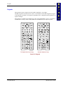
Keypads ..................................................................................................................... 37
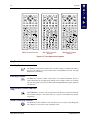
Key Functions ...........................................................................................................................38
Scan Key Function .............................................................................................................................. 38
Enter Key Function ............................................................................................................................. 38
Field Exit Key Function (IBM 5250 Only)......................................................................................... 38
Arrow / Cursor Key Function ............................................................................................................. 38
2nd Key Function................................................................................................................................ 39
CTRL Key Function............................................................................................................................ 39
ALT Key Function .............................................................................................................................. 39
SHFT Key Function ............................................................................................................................ 39
SPC Key Function............................................................................................................................... 39
Mode Key Functions........................................................................................................................... 40
CAPS Mode .....................................................................................................................................................40
Alpha to Numeric Toggle with A / # ...............................................................................................................40
Reset Key Sequence..................................................................................................................40
MX1 Reference Guide
E-EQ-MX1RG-D
Table of Contents
iii
Infrared (IR) Port........................................................................................................ 41
IR Communication Reliability ..................................................................................................41
Endcaps ..................................................................................................................... 42
COM1 / COM2 .........................................................................................................................42
RS-232 Endcap .........................................................................................................................43
Scanner Endcaps .......................................................................................................................44
Scanner Endcap LEDs and Beeper...................................................................................................... 44
Miscellaneous Connectors....................................................................................... 45
Handle Contacts ........................................................................................................................45
Battery Charging Contacts ........................................................................................................45
CHAPTER 3 POWER SUPPLY
47
Introduction ............................................................................................................... 47
Main Battery Pack ..................................................................................................... 48
LXE Docking Cradles and the MX1.........................................................................................48
Battery Charger Analyzer .........................................................................................................48
Low Battery Warning................................................................................................................49
Backup Battery.......................................................................................................... 49
Backup Battery Discharge Utility .............................................................................................49
Battery Hot-Swapping............................................................................................... 50
Status LED and the Battery.......................................................................................................50
Handling Batteries Safely......................................................................................... 51
Getting the Most from Your Batteries ......................................................................................51
Single and Multi-Unit Charging Stations................................................................. 52
Optional Clip-on Portable Charger .......................................................................... 53
Indicators...................................................................................................................................54
CHAPTER 4 SYSTEM CONFIGURATION
55
Introduction ............................................................................................................... 55
Installed Software ..................................................................................................... 55
Drive C Internal Flash Array ....................................................................................................55
Software Loaded on Drive C ....................................................................................................56
C Root Directory.......................................................................................................................57
\DOS Files.................................................................................................................................57
\AGENT ....................................................................................................................................58
\PCMCIA Files .........................................................................................................................58
\UTILS ......................................................................................................................................59
Terminal Emulation Directories................................................................................................59
Radio-Specific Subdirectory .....................................................................................................60
E-EQ-MX1RG-D
MX1 Reference Guide
iv
Table of Contents
\PCTCP (2.4GHz Radio Specific Files).............................................................................................. 60
Lucent Specific ................................................................................................................................................60
Proxim Specific................................................................................................................................................60
Cisco Specific ..................................................................................................................................................60
Symbol Specific ...............................................................................................................................................60
LXE 900Mhz Radio Files ................................................................................................................... 60
Sample AUTOEXEC.BAT File ................................................................................................61
For 900MHz Radio ............................................................................................................................. 61
For 2.4GHz Radio (with ANSI Plus) .................................................................................................. 61
Sample CONFIG.SYS File .......................................................................................................62
Sample NET.CFG Files ............................................................................................................63
Lucent Radio NET.CFG File .............................................................................................................. 63
Proxim Radio NET.CFG File.............................................................................................................. 63
Cisco Radio NET.CFG File ................................................................................................................ 64
Symbol 4121 11Mb Radio NET.CFG File ......................................................................................... 65
Sample SOCKET.CFG File ......................................................................................................67
LXE DOS Terminal Emulations ................................................................................ 69
Terminal Emulation Screen Sizes .............................................................................................69
DOS Terminal Emulation User Defined Stored Forms ............................................................69
Dual Terminal Emulation..........................................................................................................70
TE Selection Menu.............................................................................................................................. 70
Switching Terminal Emulators............................................................................................................ 70
Menu Customization ........................................................................................................................... 70
BIOS Setup ................................................................................................................ 71
Accessing the BIOS Setup ........................................................................................................71
BIOS Setup Default Values by Option .....................................................................................71
Using the Keypad......................................................................................................................72
Main Menu Options ..................................................................................................................73
Main Menu Parameters ....................................................................................................................... 73
Parameter Changes.............................................................................................................................. 73
Time .................................................................................................................................................................73
Date ..................................................................................................................................................................74
Boot..................................................................................................................................................................74
Setup Msg ........................................................................................................................................................74
Post Msg...........................................................................................................................................................75
Summary ..........................................................................................................................................................76
Advanced Menu Options ..........................................................................................................77
Parameter List ..................................................................................................................................... 77
Power Management............................................................................................................................. 78
Power Mgt........................................................................................................................................................78
CPU..................................................................................................................................................................78
Disp BL ............................................................................................................................................................79
Disp BL ............................................................................................................................................................79
Display .............................................................................................................................................................79
Suspend ............................................................................................................................................................80
Off Timer .........................................................................................................................................................80
Docked PM ......................................................................................................................................................81
Touch Wake .....................................................................................................................................................81
Power Key........................................................................................................................................................81
Keyboard............................................................................................................................................. 82
MX1 Reference Guide
E-EQ-MX1RG-D
Table of Contents
v
Caps..................................................................................................................................................................82
NumLock .........................................................................................................................................................82
Rpt Delay .........................................................................................................................................................82
Rpt Rate............................................................................................................................................................83
CtlAltDel..........................................................................................................................................................83
Other.................................................................................................................................................... 83
Font ..................................................................................................................................................................83
COM1 Pin9 ......................................................................................................................................................83
Exit Menu Options ....................................................................................................................84
Save and Exit ...................................................................................................................................... 84
Exit w/o Save ...................................................................................................................................... 84
Load Defaults ...................................................................................................................................... 84
Load Previous ..................................................................................................................................... 84
Save Changes ...................................................................................................................................... 84
API Calls .................................................................................................................... 85
Sample Code for API Calls .......................................................................................................85
CHAPTER 5 UTILITIES
87
Introduction ............................................................................................................... 87
LXE BCWEDGE ......................................................................................................... 88
Parameters .................................................................................................................................88
LXE Diagnostics........................................................................................................ 90
Backup Battery Test Utility (BBTST35.EXE) .........................................................................91
Battery Discharge Utility (BBDIS35.EXE) ..............................................................................91
Communication Port Utility (COMTST35.EXE) .....................................................................91
RS-232 Endcap COM Port Loopback Configuration ......................................................................... 92
RS-232/Scanner Endcap Connector.................................................................................................... 92
RS-232/Scanner Endcap COM Port Loopback Configuration ........................................................... 92
Display Utility (DISP35.EXE)..................................................................................................93
File Transfer Utility (LXEF.EXE) ............................................................................................93
Keyboard Utility (KEY2335.EXE)...........................................................................................93
Parameter Auto-Detect Utility (PARAM35.EXE)....................................................................94
Scanner Configuration Utility (SCU35.EXE)...........................................................................95
Set An API Function (SETAPI_4.EXE) ...................................................................................96
The NED ASCII Text Editor ....................................................................................... 97
NED Default Hot Keys .............................................................................................................98
Serial File Transfer Utility......................................................................................... 99
REMSERV................................................................................................................................99
REMDISK.................................................................................................................................99
IRSEND and IRECV Files ........................................................................................ 100
IRSEND.C...............................................................................................................................100
IRECV.C .................................................................................................................................103
CHAPTER 6 RF NETWORK CONFIGURATION
E-EQ-MX1RG-D
107
MX1 Reference Guide
vi
Table of Contents
Introduction ............................................................................................................. 107
SNMP DOS Agent.................................................................................................... 107
NET.CFG Parameters.............................................................................................. 108
Lucent Parameters...................................................................................................................108
Link Support ..................................................................................................................................... 108
Protocol ............................................................................................................................................. 108
WaveLAN_Network_Name.............................................................................................................. 108
Station_Name.................................................................................................................................... 108
AP_Distance...................................................................................................................................... 108
Microwave_Robustness .................................................................................................................... 109
Transmit_Rate ................................................................................................................................... 109
Medium_Reservation ........................................................................................................................ 109
Card_Power_Management ................................................................................................................ 110
Maximum_Sleep_Duration ............................................................................................................... 110
Receive_All_Multicasts .................................................................................................................... 110
Enable_Encryption............................................................................................................................ 110
Transmit_Key_ID ............................................................................................................................. 110
Proxim Parameters ..................................................................................................................111
Link Support ..................................................................................................................................... 111
Protocol ............................................................................................................................................. 111
Int ...................................................................................................................................................... 111
Port .................................................................................................................................................... 111
Mem#1 (ODI).................................................................................................................................... 111
Domain.............................................................................................................................................. 111
Station_type ...................................................................................................................................... 111
Socket................................................................................................................................................ 111
Initialize_365 .................................................................................................................................... 112
Inactivity_min ................................................................................................................................... 112
Inactivity_sec .................................................................................................................................... 112
Channel ............................................................................................................................................. 112
Subchannel ........................................................................................................................................ 112
Mac_optimize.................................................................................................................................... 112
Roam_config ..................................................................................................................................... 112
Peer_to_peer...................................................................................................................................... 113
Cisco Parameters.....................................................................................................................114
Link Support ..................................................................................................................................... 114
Protocol ............................................................................................................................................. 114
SSID .................................................................................................................................................. 114
LEAP................................................................................................................................................. 114
WorldMode ....................................................................................................................................... 114
ShortPreamble ................................................................................................................................... 114
AWCLEAP ....................................................................................................................................... 115
FragThreshold ................................................................................................................................... 115
RTSThreshold ................................................................................................................................... 115
DataRateX ......................................................................................................................................... 115
RefreshInterval.................................................................................................................................. 115
PowerSaveMode ............................................................................................................................... 115
MaxPowerSave ................................................................................................................................. 115
NodeName......................................................................................................................................... 116
MX1 Reference Guide
E-EQ-MX1RG-D
Table of Contents
vii
WEP enable....................................................................................................................................... 116
Diversity............................................................................................................................................ 116
PortBase – IRQ – Memory - Socket ................................................................................................. 116
BusType ............................................................................................................................................ 116
Frame ................................................................................................................................................ 116
LongRetryLimit ................................................................................................................................ 116
WEPDOS .......................................................................................................................................... 117
Symbol Parameters..................................................................................................................118
Link Support ..................................................................................................................................... 118
Protocol ............................................................................................................................................. 118
ESS_ID.............................................................................................................................................. 118
mode.................................................................................................................................................. 118
ioaddress............................................................................................................................................ 118
memory ............................................................................................................................................. 118
interrupt............................................................................................................................................. 118
performance_index............................................................................................................................ 118
Auth_type.......................................................................................................................................... 119
Encrypt_Key# ................................................................................................................................... 119
encrypt_enable .................................................................................................................................. 119
Encrypt_Key_ID ............................................................................................................................... 119
Encrypt_Enable_Index...................................................................................................................... 119
diversity............................................................................................................................................. 119
Tx_rate .............................................................................................................................................. 119
SOCKETS TCP/IP Stack.......................................................................................... 120
Introduction.............................................................................................................................120
Bootp................................................................................................................................................. 120
DHCP ................................................................................................................................................ 120
Setting SOCKETS.CFG Parameters .......................................................................................121
Set IP Address ................................................................................................................................... 121
Set ARP INIT.................................................................................................................................... 121
Set Interface ...................................................................................................................................... 121
Set Router IP (Gateway only) ........................................................................................................... 122
Set Domain Name Server.................................................................................................................. 122
Display IP Address............................................................................................................................ 122
Options .............................................................................................................................................. 122
SOCKET.CFG Parameters......................................................................................................123
domain............................................................................................................................................... 123
iface................................................................................................................................................... 124
interface............................................................................................................................................. 124
ip ....................................................................................................................................................... 127
param................................................................................................................................................. 128
route .................................................................................................................................................. 130
tcp...................................................................................................................................................... 132
CHAPTER 7 TROUBLESHOOTING
135
Problem Determination Tips .................................................................................. 135
Startup Problems .................................................................................................... 137
E-EQ-MX1RG-D
MX1 Reference Guide
viii
Table of Contents
Bypassing the Configuration Files..........................................................................................137
Verifying Boot Order ..............................................................................................................137
Missing COMMAND.COM ...................................................................................................138
Edit BIOS Setup................................................................................................................................ 138
Copy File........................................................................................................................................... 139
Setting System Time and Date................................................................................................140
Hardware Problems ................................................................................................ 141
Power Source ..........................................................................................................................141
Keypad ....................................................................................................................................141
Display ....................................................................................................................................142
The Display has Turned Dark or Very Light .................................................................................... 142
Full Alpha-Numeric Keypad..........................................................................................................................142
Numeric-Alpha Keypad .................................................................................................................................142
Hard Disk Drive ......................................................................................................................142
PCMCIA Cards .......................................................................................................................143
Upper Memory Conflicts .................................................................................................................. 144
IRQ Assignments ....................................................................................................................144
Optional Devices.....................................................................................................................145
Radio Problems....................................................................................................... 146
The 2.4GHz Radios.................................................................................................................146
The 900MHz Radios ...............................................................................................................146
Software Related Problems.................................................................................... 147
IP Stack ...................................................................................................................................147
Memory .................................................................................................................... 148
Conventional Memory ............................................................................................................148
Extended Memory...................................................................................................................148
System Testing........................................................................................................ 149
Power On Self Test (POST)....................................................................................................149
POST Error Messages .............................................................................................................149
Messages Probably Requiring Repair .....................................................................................150
POST Beep Codes...................................................................................................................150
If You Need Further Assistance ............................................................................. 151
APPENDIX A KEY MAPS
153
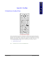
Full Alpha-Numeric Key Map (60 Key)................................................................... 153
Full Alpha-Numeric Key Map 101-Key Equivalencies for Batch Units ................................154
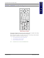
IBM 3270 and TN3270 Terminal Emulator Keypad ..............................................................159
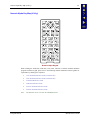
IBM 5250 and TN5250 Terminal Emulator Keypad ..............................................................160
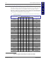
Numeric-Alpha Key Map (41 Key) .......................................................................... 161
Numeric-Alpha Key Map 101-Key Equivalencies for Batch Units .......................................162
APPENDIX B TECHNICAL SPECIFICATIONS
MX1 Reference Guide
167
E-EQ-MX1RG-D
Table of Contents
ix
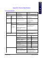
Physical Specifications .......................................................................................... 167
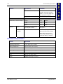
Environmental Specifications ................................................................................ 168
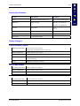
Display Specifications ............................................................................................ 169
Battery Chargers ..................................................................................................... 169
Clip-on Portable Charger ........................................................................................................169
US AC Wall Adapter ..............................................................................................................169
International AC Adapter........................................................................................................169
Radio Specifications............................................................................................... 170
PCMCIA 900 MHz Type III ...................................................................................................170
LXE 6400 PCMCIA 2.4 GHz Type II ....................................................................................170
LXE 6500 PCMCIA 2.4 GHz Type II ....................................................................................170
PCMCIA Cisco 2.4 GHz Type II............................................................................................171
PCMCIA Symbol 11Mb 2.4 GHz Type II ..............................................................................171
APPENDIX C COMMANDS
173
Introduction ............................................................................................................. 173
ROM-DOS Commands ............................................................................................ 173
ANSI.SYS ...............................................................................................................................173
ATTRIB.EXE..........................................................................................................................174
CHKDSK.EXE........................................................................................................................175
COMMAND.COM .................................................................................................................176
DELTREE.EXE ......................................................................................................................177
FORMAT.COM ......................................................................................................................178
HIMEM.SYS...........................................................................................................................179
MEM.EXE ..............................................................................................................................181
MODE.COM...........................................................................................................................181
MORE.COM ...........................................................................................................................183
NED.EXE and NED.CFG .......................................................................................................184
PRINT.COM ...........................................................................................................................185
REMDISK.EXE ......................................................................................................................186
REMSERV.EXE .....................................................................................................................187
SYS.COM ...............................................................................................................................189
VER.........................................................................................................................................190
XCOPY.COM .........................................................................................................................191
ROM-DOS 6.22 Command Summary ..................................................................... 192
INDEX
E-EQ-MX1RG-D
197
MX1 Reference Guide
x
Table of Contents
Illustrations
Figure 1-1 The MX1 Hand Held Computer...................................................................................................... 1
Figure 1-2 MX1 Components ........................................................................................................................... 7
Figure 1-3 Open Battery Door .......................................................................................................................... 8
Figure 1-4 Inserting Battery Pack ..................................................................................................................... 8
Figure 1-5 MX1 With Handstrap...................................................................................................................... 9
Figure 1-6 Upper Strap Bracket........................................................................................................................ 9
Figure 1-7 Strap Inserted in Upper Bracket ...................................................................................................... 9
Figure 1-8 Pistol-Grip Handle and Contacts on the Back of the MX1 ........................................................... 11
Figure 1-9 Connect Handle to MX1 ............................................................................................................... 12
Figure 1-10 Location of the Power Button ..................................................................................................... 13
Figure 1-11 Scanner Endcap........................................................................................................................... 15
Figure 1-12 Scanner / RS-232 Endcap............................................................................................................ 15
Figure 1-13 RS-232 Endcap ........................................................................................................................... 15
Figure 1-14 Plain Endcap................................................................................................................................ 16
Figure 1-15 Scanner Endcap LEDs and Beeper.............................................................................................. 16
Figure 1-16 MX1 Endcap with O-Ring Gasket .............................................................................................. 18
Figure 1-17 Endcap and ZIF Ribbon Connector............................................................................................. 18
Figure 1-18 Insert / Remove PC Card............................................................................................................. 20
Figure 2-1 System Hardware .......................................................................................................................... 27
Figure 2-2 Location of the Power (PWR) Button ........................................................................................... 30
Figure 2-3 Power Status and the Status LED.................................................................................................. 31
Figure 2-4 MX1 Display................................................................................................................................. 33
Figure 2-5 Keypads......................................................................................................................................... 37
Figure 2-6 Three Special Use Keypads........................................................................................................... 38
Figure 2-7 Infrared Port - COM2 Port ............................................................................................................ 41
Figure 2-8 9-Pin RS-232 Description ............................................................................................................. 43
Figure 2-9 Scanner Endcap LEDs and Beeper................................................................................................ 44
Figure 2-10 Handle Contacts .......................................................................................................................... 45
Figure 2-11 Battery Charging Contacts .......................................................................................................... 45
Figure 3-1 Battery Compartment .................................................................................................................... 47
Figure 3-2 Main Battery Pack......................................................................................................................... 48
Figure 3-3 Battery and Battery Charging Cup ................................................................................................ 48
Figure 3-4 Multidock and Single Dock Communicating Charger .................................................................. 52
Figure 3-5 Insert MX1 in Cradle .................................................................................................................... 52
Figure 3-6 Clip-on Portable Charger .............................................................................................................. 53
Figure 5-1 MX1 RS-232 Endcap Serial Connector (COM1) and Pinout ....................................................... 91
Figure 5-2 RS-232 Endcap COM Port Loopback Configuration ................................................................... 92
Figure 5-3 MX1 RS-232/Scanner Endcap Serial Connector (COM1) and Pinout ......................................... 92
Figure 5-4 RS-232/Scanner Endcap COM Port Loopback Configuration...................................................... 92
MX1 Reference Guide
E-EQ-MX1RG-D
Chapter 1 Introduction
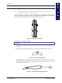
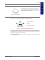
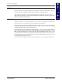
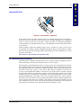
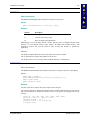
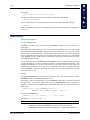
The MX1 is a rugged, portable, hand-held PC-compatible computer capable of wireless data
communications while being carried. The MX1 can transmit information using either a 900 MHz
or 2.4 GHz radio. It can store information for later transmission through an RS-232 or InfraRed
port. The MX1 is vertically oriented and features backlighting for the display.
The MX1 is a DOS compatible computer designed to run as a batch unit or to run software
applications such as LXE’s Terminal Emulator applications (ANSI Plus, LDS Plus, DOS 5250,
DOS 3270, TN3270 and TN5250).
The heart of the MX1 is an Intel® 486 processor that is PC compatible. The MX1 features a
graphics screen with electroluminescent backlight. The keypad is constructed of a phosphorescent
material that needs no backlighting. The case is constructed of high-impact plastic designed to
withstand multiple drops in an industrial environment.
Figure 1-1 The MX1 Hand Held Computer
Note:
E-EQ-MX1RG-D
The "MX1 Installation and Operator’s Guide” contains MX1 operating instructions for
the general user. The guide is contained on the LXE Manuals CD.
MX1 Reference Guide
2
When to Use This Guide
When to Use This Guide
As the reference for LXE’s MX1 computer, this guide provides detailed information on its
features and functionality. Use this reference guide as you would any other source book -- reading
portions to learn about the MX1, and then referring to it when you need more information about a
particular subject. This guide takes you through all aspects of the installation and configuration of
the LXE MX1.
Operating instructions for the general user are contained in the “MX1 Installation and Operator’s
Guide”.
This chapter, “Introduction”, briefly describes this reference guide structure, contains setup and
installation instruction, and briefly describes data entry processes.
Chapter 2 “Physical Description and Layout” describes the function and layout of the
configuration, controls and connectors on the MX1.
Chapter 3 “Power Supply” describes the power sources and battery charging stations.
Chapter 4 “System Configuration” takes you through the BIOS Setup and memory maps, the
MX1 file structure, describes LXE’s Terminal Emulation programs compatible with the MX1 and
contains instructions for panning the display.
Chapter 5 “Utilities” explains the function of MX1-specific utilities.
Chapter 6 “RF Network Configuration” describes the functions and delivers instruction on
changing RF networked radio configurations.
Chapter 7 “Troubleshooting” solutions are split into several areas. The solution may be found in
one area or it may be a combination of the solutions in several areas. This chapter also contains
POST messages and run time messages.
Appendix A “Key Maps” describes the keypress sequences for the different keypads – the full
alpha-numeric keypads (ANSI, 3270, 5250) and the numeric-alpha keypad.
Appendix B “Technical Specifications”
environmental, display and the radios.
lists
technical
specifications
for
physical,
Appendix C “Commands” presents a listing and description of ROM-DOS command files.
MX1 Reference Guide
E-EQ-MX1RG-D
When to Use This Guide
3
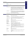
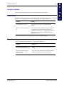
Document Conventions
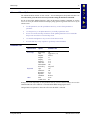
This reference guide uses the following document conventions:
ALL CAPS
Menu|Choice
“Quotes”
<
>
All caps are used to represent disk directories, file names, and application
names.
Rather than use the phrase “choose the Save command from the File menu”,
this manual uses the convention “choose File|Save”.
Indicates the title of a book, chapter or a section within a chapter (for example,
“Document Conventions”).
Indicates a key on the keyboard (for example, <Enter> ).
Indicates a reference to other documentation.
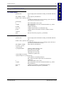
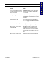
ATTENTION
!
Keyword that indicates vital or pivotal information to follow.
Attention symbol that indicates vital or pivotal information to follow. Also,
when marked on product, means to refer to the manual or operator’s guide.
International fuse replacement symbol. When marked on the product, the label
includes fuse ratings in volts (v) and amperes (a) for the product.
Note:
Caution
!
WARNING
!
DANGER
!
E-EQ-MX1RG-D
Keyword that indicates immediately relevant information.
Keyword that indicates a potentially hazardous situation which, if not avoided,
may result in minor or moderate injury.
Keyword that indicates a potentially hazardous situation which, if not avoided,
could result in death or serious injury.
Keyword that indicates a imminent hazardous situation which, if not avoided,
will result in death or serious injury.
MX1 Reference Guide
4
Getting Started
Getting Started
Note:
When your MX1 is pre-configured, the radio card or PCMCIA data card and endcaps
are assembled by LXE to your specifications. You may only need to install a handle or
handstrap.
This section’s instructions are based on the assumption that your new system is pre-configured
and requires only accessory installation (e.g. handstrap or handle) and a power source.
LXE recommends that installation or removal of accessories be performed on a clean, well-lit
surface. When necessary, protect the work surface, MX1, and components from electrostatic
discharge.
In general, the sequence of events is:
1.
Insert fully charged battery.
2.
Install accessories.
3.
Power the MX1 on.
4.
Configure the software.
Note:
New batteries must be fully charged prior to use. This process takes approximately three
hours per battery. LXE batteries are charged using LXE Battery Charger/Analyzers.
Refer to the documentation received with the battery charger / analyzer for
operating instruction and technical information.
Quick Start -- Configure the Software
Please have the following information available before setting up your computer for the first time:
•
IP Address
•
Network SSID number of the Access Point
In Brief . . .
1.
Insert a fully charged battery into a hand-held computer. Connect a vehicle mounted
computer to an external power source.
2.
Power up the computer.
3.
Using the NED editing utility, edit the NET.CFG file in the PCTCP subdirectory.
4.
Using the NED editing utility, edit the SOCKET.CFG file in the PCTCP subdirectory.
5.
Using the TE utility, edit the Terminal Emulation parameters (if needed).
6.
Reboot.
MX1 Reference Guide
E-EQ-MX1RG-D
Quick Start -- Configure the Software
5
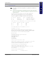
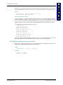
How To Edit DOS Files on Your Computer Using NED.EXE
The following DOS file edit commands are required for setup. These commands are not case
sensitive. The following keystrokes will control ths cursor.
PgDn - Move cursor down
PgUp - Move cursor up
2nd PgUp - Move up a page
2nd PgDn - Move down a page
2nd CTRL PgUp - Move to the top of the file
2nd CTRL PgDn - Move to the bottom of the file
The cursor may not be visible on the screen. Use the key commands above to find the cursor when
editing the NET.CFG and SOCKET.CFG files.
If the cursor is at the bottom of the file, the PgDn key and the 2nd PgDn keystrokes will not help
you find the cursor.
How To Use F5 During Bootup
1.
Power the computer on.
2.
Press F5 when “Starting ROM-DOS” appears on the screen. It may flash quickly on the
screen then disappear.
3.
Press the Enter key at the Time prompt. Press the Enter key at the date prompt.
4.
Type CLS and press the Enter key.
5.
Type “Path=C:\DOS” and press the Enter key.
6.
The DOS C:\ prompt appears on the screen.
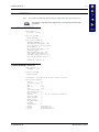
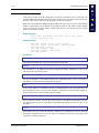
How To Edit the NET.CFG File
Note:
While editing the NET.CFG file, do not press Enter until all changes are completed.
1.
At the C:\ prompt, type CD PCTCP. Then press Enter.
2.
At the C:\PCTCP prompt, type NED NET.CFG. Then press Enter.
3.
You should be at the top of the file. Use the PgDn (or down arrow) key to move down the
screen. You may not see the cursor at first.
4.
Move the cursor to the line of code that reads:
SSID
“” ; Must match Cisco Access Point setting
ESS_ID “” ; Must match Symbol Access Point setting
WaveLan_Network_Name “” ; Must match Lucent/Orinoco/Agere Access Point setting
E-EQ-MX1RG-D
5.
At this line, move the cursor to the right using the End (or the right arrow) key
6.
Edit the line to contain the network name of the Access Point the computer is to connect
through.
7.
If you will be using WEP or another authentication protocol, please contact your wireless
network administrator to acquire the WEP/LEAP keys. Please refer to Chapter 6, “RF
Network Configuration” for the WEP key procedure.
8.
After edits are complete, press Alt F to access the menu and save.
9.
Move the cursor down to Save or press Enter or press F9.
MX1 Reference Guide
6
Quick Start -- Configure the Software
10. To exit, press Alt F.
11. Move the cursor to Exit and press Enter or press Alt F4.
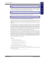
How To Edit the SOCKET.CFG File
Note:
While editing the SOCKET.CFG file, do not press Enter until all changes are completed.
1.
At the C:\ prompt, type CD PCTCP. Press Enter.
2.
At the C:\PCTCP prompt, type NED SOCKET.CFG. Press Enter.
3.
You should be at the top of the file. Use the PgDn key (or down arrow) to move down the
screen. You may not see the cursor at first.
4.
Move the cursor down to the line that reads:
IP address 0.0.0.1/16 // This is the default setting and allows the DHCP server to set the
computer’s IP address to be set each time the computer is
powered up.
5.
If a static IP address is to be set for the computer, edit this statement to read:
IP address ‘assigned IP address’/xx
where ’xx’ is the number of subnet bits for the assigned IP address.
Note:
If a static address was set, then a route might also be required if there is a gateway
between the Access Points the system uses and a Session Manager (if used).
6.
After edits are complete, press Alt F to access the menu.
7.
Move the cursor down to Save or press Enter or press F9.
8.
To exit, press Alt F.
9.
Move the cursor to Exit and press Enter or press Alt F4.
MX1 Reference Guide
E-EQ-MX1RG-D
Components
7
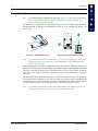
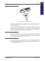
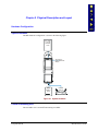
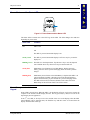
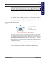
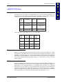
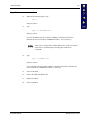
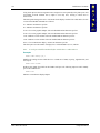
Components
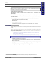
1. Endcap
2. Scan Indicators
3. Beeper
4. Status Indicator
5. Display
6. Scan Buttons
7. Keypad
8. Power Button
9. IR Port
MX1 Front
1. Scan Aperture
2. Warning Label
3. Upper Handstrap Connection
4. Handle Contacts
5. Battery Cover Latch
6. Lower Handstrap Connection
MX1 Back
Figure 1-2 MX1 Components
Note:
E-EQ-MX1RG-D
MX1 Back : Handle contacts (4) are covered with a label. The label must be removed
before the handle is attached. When the handle is removed, the label should be replaced
to keep the contacts clean.
MX1 Reference Guide
8
Components
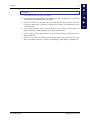
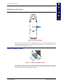
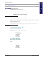
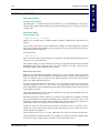
Insert Battery Pack
Note:
New batteries must be charged prior to first use. This process takes approximately three
hours in an LXE Battery Charger/Analyzer and eight hours with the LXE Clip-on
Portable Charger attached to the MX1.
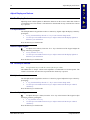
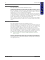
The MX1 Battery Compartment is located on the lower rear of the computer. Open the Battery
Compartment door by sliding the door latch down (at the top of the compartment). Remove the
battery door.
Figure 1-3 Open Battery Door
Note:
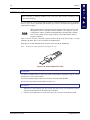
Figure 1-4 Inserting Battery Pack
If a hand strap is attached to the unit, there is no need to remove the strap – just open the
closed loop fastener. See sections titled “Attach Hand Strap” and “Install Pistol Grip
Handle” for instruction.
These illustrations show the battery compartment with the door removed. The Battery Contacts (1)
provide the electrical link between the battery pack and the computer. Care should be used when
inserting or removing the battery pack so that damage does not occur to the contacts. If damage
does occur, cease using the unit until inspection or repair can be performed by a qualified
technician.
The MX1 Battery Pack should be inserted tab (2) end first so that the tab mates with the hole at
the top of the battery compartment. The battery will then lay inside the battery compartment but
will not be secure. To secure the battery, the battery compartment door must be in place and the
door latch locked. This provides the tension necessary to hold the battery pack in place.
Note:
MX1 Reference Guide
If a handstrap is installed, the battery door latch is hidden by the handstrap. Loosen the
handstrap and shift it out of the way to have access to the battery door.
E-EQ-MX1RG-D
Components
9
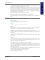
Attach Hand Strap (Optional)
Note:
An Upper Strap Bracket installation is a requirement prior to using the MX1 in a
Docking Station. The strap is not a requirement.
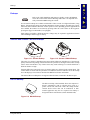
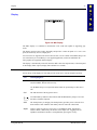
An elastic handstrap is available for the MX1. Once installed, the handstrap provides a means for
the user to secure the computer to a hand. It is adjustable to fit practically any size hand and is
easily moved to allow installation or removal of the MX1 battery pack.
Figure 1-5 MX1 With Handstrap
Tool Required: #1 Phillips Screwdriver
Installation
1.
If a handle is installed, remove it at this time. See section “Install Pistol Grip Handle” for
instruction.
2.
Slip the strap through the upper bracket prior to securing the upper bracket to the unit.
Figure 1-6 Upper Strap Bracket
3.
When slipping the strap through the bracket make sure the closed loop fastener surface is up.
After slipping the strap through the bracket, fold the strap over so that the two closed loop
fastener surfaces mate evenly.
Figure 1-7 Strap Inserted in Upper Bracket
E-EQ-MX1RG-D
MX1 Reference Guide
10
Components
4.
Prior to securing the upper bracket to the unit, install the provided pin through the bottom
opening of the strap. Insert the pin into the strap slot on the bottom, rear of the MX1. Insure
that both ends of the pin are securely installed.
5.
After securing the bottom of the strap to the unit, loosen the closed loop fastener strap and
then secure the upper bracket to the unit with a screw.
Removal
1.
Separate the Closed loop fastener tabs and loosen the strap through the upper bracket.
2.
Using a Phillips Screwdriver, remove the upper bracket screw.
3.
Using a flat object depress either end of the pin at the bottom of the handstrap. Once the pin is
depressed the pin should easily slip out of the strap slot.
MX1 Reference Guide
E-EQ-MX1RG-D
Components
11
Install Pistol Grip Handle (Optional)
The MX1 can be purchased with a customer-installable pistol grip handle. The handle allows the
operator to hold the unit and activate the scanner with one hand. The handle is built of a durable
and flexible plastic that is designed to detach from the MX1 if the unit is dropped.
Figure 1-8 Pistol-Grip Handle and Contacts on the Back of the MX1
The top of the handle features a cradle arrangement with plastic tabs on each side that are
designed to mate with the MX1 and provide a firm grip on the case. The handle features an
integral trigger that is connected to the MX1 unit through contacts on the back of the MX1. The
trigger contacts mate with contacts on the back of the MX1 when the handle is installed. When the
handle is not installed, the MX1 contacts should be covered with the protective label delivered
with the MX1.
Note:
If a handstrap is installed, the handle trigger contacts are hidden by the handstrap.
Remove the handstrap before installing the pistol-grip handle.
Preparation
Remove the protective adhesive Mylar label covering the handle contacts on the back of the MX1
unit. The contacts should be clean and free from obstructions. The MX1 unit must not have any
other handle or strap installed. If a handle or strap is installed, remove it at this time.
E-EQ-MX1RG-D
MX1 Reference Guide
12
Components
Installation
Figure 1-9 Connect Handle to MX1
In one hand grasp the MX1 unit so that the keypad is facing up and the endcap away from you. In
the other hand grasp the pistol-grip by the handle with the u-shaped cradle up and the trigger
mechanism away from you.
Place the pistol-grip handle u-shaped cradle under the MX1 unit and align the slots (2) on the
upper ends of the u-shaped cradle with the tabs (1) in the slots on the sides of the MX1 unit. Press
the MX1 unit into the u-shaped cradle until one of the tabs slides into the slot. Press the other tab
slot over the other tab until you feel a positive catch. You should hear a “click” as the units join.
Cautiously test the handle and unit to ensure proper, secure installation.
Removal
Insert a strong, flat object into one of the slots and gently pry the u-shaped cradle away from the
MX1 unit. Do not drop the MX1 unit. Once the pistol-grip handle is no longer secured to the MX1
unit pull the handle directly away from the unit. Do not slide the unit in the u-shaped cradle since
that may damage the contacts of either the handle or the unit.
Use and Operation
The pistol-grip handle enables the user of the MX1 to hold the unit while pointing and activating
the scanner with one hand. Pressing the trigger activates the scanner and functions the same as the
SCAN key on the keypad. With the handle installed the SCAN key on the keypad remains active.
The trigger duplicates the operation.
MX1 Reference Guide
E-EQ-MX1RG-D
Components
13
Power On and Off
Turn On the MX1
Press the Power button until the display turns on. The power button is located at the bottom of the
keypad.
Figure 1-10 Location of the Power Button
When the MX1 is powered on, the display will begin scrolling power-on information as software
and drivers are loaded. When the display has stopped scrolling and a DOS prompt is displayed or
an application begins, the power on sequence is complete. (The Power Key can be disabled – see
Power Key in BIOS Setup.)
Turn Off the MX1
Hold the Power button down. The unit will emit three short beeps and one long beep. After the
long beep the MX1 will power down. The Power button and the display will turn off.
Note:
Quickly tapping or releasing the Power button prior to the one long beep signal will
place the MX1 in Suspend mode (if Suspend is enabled, see Power Key in BIOS Setup to
configure the Suspend function).
Troubleshooting
The MX1 will not turn off – force a Power Off by holding the Power key down for 15 seconds
and the MX1 will power off. Locate and correct the problem before powering the MX1 back on –
e.g. very low battery power, radio conflict, unexpected software application result, etc.
E-EQ-MX1RG-D
MX1 Reference Guide
14
Adjust Display and Volume
Adjust Display and Volume
Set The Display Contrast
Adjusting screen contrast lightens or darkens the characters on the screen to make them visible at
a comfortable level. The contrast is incremented or decremented one step each time the contrast
key is pressed.
Full Alpha-Numeric
The full alpha-numeric keypad does not have a contrast key legend. Adjust the display contrast by
pressing the:
•
•
2nd key, then the Shft key then the <C> key to enter Contrast change mode.
Use the Up Arrow and Down Arrow keys to adjust contrast until the display lightens or
darkens to your satisfaction.
Press the Enter key to exit this mode.
Numeric-Alpha Keypad
To adjust screen contrast, locate the <F11> key at the bottom of the keypad. Adjust the
display contrast by pressing the:
•
•
2nd key, then the <F11> key
Use the Up Arrow and Down Arrow keys to adjust contrast until the display lightens or
darkens to your satisfaction.
Press the Enter key to exit this mode.
Set The Beeper Volume
Note:
An application may override the control of the beeper volume.
The audible alert or “beeper” volume can be adjusted to a comfortable level for the operator. The
volume is increased or decreased one step each time the volume key is pressed.
Full Alpha-Numeric
The full alpha-numeric keypad does not have a Volume key legend. Adjust the beeper volume by
pressing the:
•
•
2nd key, then the Shft key then the <V> key to enter Volume change mode.
Use the Up Arrow and Down Arrow keys to adjust contrast until the beeper volume is
satisfactory.
Press the Enter key to exit this mode.
Numeric-Alpha Keypad
To adjust the beeper volume, locate the <F12> key at the bottom of the keypad. Adjust
the beeper volume by pressing the:
•
•
2nd key, then the <F12> key
Use the Up Arrow and Down Arrow keys to adjust contrast until the beeper volume is
satisfactory.
Press the Enter key to exit this mode.
MX1 Reference Guide
E-EQ-MX1RG-D
Endcaps
15
Endcaps
Refer to the “MX1 Installation and Operator’s Guide” on the LXE Manuals
CD for the section titled “Scanner Warnings and Labels” for important laser
safety information before using the scanner.
Several scanner endcaps are available with the MX1. These consist of a High Performance, Long
Range, Advanced Long Range and 2D Decoded Raster scanner endcaps. Externally they appear
alike with similar indicators. Barcode scanner operation varies depending upon the application but
once enabled, the scanners are activated by pressing either the “Scan” button on the keypad or
pressing the trigger on the handle (if so equipped).
Each endcap type fulfills a different function. Changes may be required in application software
when installing a different type of endcap.
Scanner and Scanner / RS-232 Endcaps
Figure 1-11 Scanner Endcap
Figure 1-12 Scanner / RS-232 Endcap
The range of a scanner is dependent upon many outside influences including size of the barcode,
quality of the barcode printing, material the barcode is printed on, and angle of the scanner endcap
relative to the barcode label. Any of these factors may result in having to re-scan the label from a
different distance or angle.
External differences between the types of scanner engines are reflected in the scanner labels. The
scanner labels are on the side away from the scan indicators (the three indicators are on the endcap
above the display). The scanner is labeled with CDRH Class II laser information.
The Scanner/RS-232 endcap does not support tethered scanners connected to the RS-232 port.
RS-232 Endcap
The RS-232 endcap, when installed, allows the computer to
directly communicate with an external device such as a
printer. An RS-232 cable must connect the endcap and the
external device before data can be transferred. A data
transfer application may also be required. The endcap is
designed for IP65 environments (with an installed radio).
Figure 1-13 RS-232 Endcap
E-EQ-MX1RG-D
MX1 Reference Guide
16
Endcaps
Plain Endcap
The Plain Endcap is used when other endcap options are not
selected. It provides a seal against dirt and moisture for the
top of the computer case. The endcap is designed for IP65
environments (with an installed radio).
Figure 1-14 Plain Endcap
Scanner Endcap Indicators
Read all cautions, warnings and labels before using the scanner endcaps.
1. Laser On Indicator
2. Beeper
3. Good Read Indicator
Figure 1-15 Scanner Endcap LEDs and Beeper
The left LED (1 - Laser On Indicator) on the top of the laser barcode endcap will light, indicating
laser emission when the laser beam is being emitted. Following a good read, the right LED (3 Good Read Indicator) flashes, indicating a successful scan. Beeps may be heard after a good read,
depending on the application running on the MX1.
The laser automatically turns off after a successful read and is ready to scan again when the Scan
key (or the trigger) is pressed.
MX1 Reference Guide
E-EQ-MX1RG-D
Endcaps
17
Endcap Removal and Installation
When removing or installing the endcaps, protect the MX1 internal components and these
particular accessories from electrostatic discharge.
All MX1 endcaps are installed similarly.
The software that controls the endcap will vary so endcap types are not considered easily
interchangeable.
After installation of an endcap is complete, use the endcap for its intended function. If the
operation is unsuccessful or erratic, remove and reinstall the ribbon connector – the Zero Insertion
Force (ZIF) connector.
There are four types of scanner endcaps. All four are installed on the MX1 in the same way –
1.
carefully place rubber o-ring gasket1 on the endcap,
2.
attach ZIF cable,
3.
snap the endcap onto the MX1,
4.
screw the endcap to the MX1, torquing the screws to no more than 3 in/lb. (.34 N/m).
ZIF Connector
All MX1 endcaps use ZIF connectors to maintain permanent connection between the endcap and
the MX1.
The Zero Insertion Force (ZIF) Connector is a way to electronically connect devices without using
excessive force during the installation of cables. Excessive force can cause bent connector pins or
misaligned and/or damaged cables.
•
Caution must be exercised when handling the endcaps. The electrical connectors are
delicate and may damage easily.
•
The ZIF connector is on the right hand side inside the cap when the MX1 is face up.
Preparation
1.
If a handle is installed, remove it at this time.
2.
Caution must be exercised when handling the endcaps. The electrical connectors are delicate
and may damage easily.
3.
Caution must be exercised when handling o-ring gaskets as they are delicate and may break if
stretched.
4.
Carefully align the o-ring to the endcap before reattaching the endcap.
1
E-EQ-MX1RG-D
The o-ring is directional and must be placed right side up on the endcap seal.
MX1 Reference Guide
18
Endcaps
Tools Required: #1 Phillips Screwdriver
1. ZIF Connector
2. Rubber O-Ring Gasket
3. O-Ring Gasket Slot
Figure 1-16 MX1 Endcap with O-Ring Gasket
1. ZIF Connector
2. ZIF Cable or Ribbon
Cable
3. Curved Edge
4. Middle Screw Set
Figure 1-17 Endcap and ZIF Ribbon Connector
Removal
1.
Using a #1 Phillips screwdriver, remove the two screws securing the endcap. These screws
are located on the upper rear of the unit.
2.
Loosen the two screws in the middle (number 4 on the figure titled “Endcap and ZIF Ribbon
Connector”. Do not remove middle screws.
3.
When the top screws are removed detach the endcap and separate it from the MX1 unit no
more than the length of the ribbon connector still connecting the endcap to the unit.
4.
Carefully lift up the lock mechanism on the ZIF connector.
Note:
Use caution when performing this task since excessive pulling or twisting of the
connector may result in damage to either the unit, the endcap and/or the ribbon
connector.
5.
Disconnect the ribbon cable from the ZIF connector in the endcap only.
6.
If you anticipate keeping the endcap removed from the unit for a long period of time place the
endcap in an enclosed storage container. Store in an area that is protected from dirt, moisture,
and electrostatic contact.
MX1 Reference Guide
E-EQ-MX1RG-D
Endcaps
19
Installation
E-EQ-MX1RG-D
1.
Lay the MX1 unit face up on the work surface.
2.
Carefully align the O-Ring Gasket in the O-Ring Gasket Slot -- making sure the curved edge
of the side tabs are towards the back of the endcap.
3.
Position the endcap with the open side of the endcap toward the open side of the unit.
Connect the ribbon cable to proper ZIF connectors in the endcap. (See the Removal section
on ZIF connectors.)
4.
Gently separate the MX1 front cover from the back cover and mate the open ends of the
endcap and the unit without pinching or stretching the O-Ring Gasket.
5.
Check to make sure the ribbon connector is not pinched or otherwise caught between the
endcap and the unit.
6.
Place the screws in the screw holes on the back of the MX1. Torque the screws to no more
than 3 inch pounds of pressure (.34 N/m). Overtorquing may cause damage to the MX1 unit.
MX1 Reference Guide
20
Endcaps
PCMCIA Card Slot
When removing or installing PCMCIA cards, protect the MX1 internal components from
electrostatic discharge.
Use and operation of the Personal Computer Memory Card International Association (PCMCIA)
device (e.g. PC card) is dependent upon both the type of device installed and the application(s)
running on the computer.
When installed, the PC card will not function properly unless the proper PC card
management software is installed in the PC card/MX1. (See Chapter 4, “System
Configuration” and the “PCMCIA Card Management and LXE DOS Computers
User’s Guide”.) Make sure the proper software is pre-loaded and PC cards are
properly configured.
There is one PC card slot in the MX1 typically used for the PC radio card. If there is a radio
installed in the MX1, there is no slot available for an SRAM card.
When there is no radio installed, the PC card slot can be used for the SRAM card.
Note:
Remove the radio card before installing a PC card.
Figure 1-18 Insert / Remove PC Card
Preparation
If a handle is installed, remove it at this time. LXE recommends that installation of the PC card be
performed on a clean, well-lit surface.
Loosen the installed endcap to allow access to the PC card slots inside the MX1.
Do not remove the endcap, instead, hold it out of the way.
Installation
1.
Slide the PC Card, connector side first, into the slot until it seats. Use caution not to pull or
snag the antenna connector on the Radio card, if installed.
2.
If the PC Card is difficult to seat in the slot, remove the card, turn it around and re-install.
MX1 Reference Guide
E-EQ-MX1RG-D
Endcaps
21
Removal
1.
Grasp the top of the PC Card and pull it straight upward to remove.
2.
Use caution not to pull or snag the antenna connector on the Radio card, if installed.
If you anticipate keeping the PC card out of the MX1 for a long period of time place it in an
enclosed storage container. Store in an area that is protected from dirt, moisture, and electrostatic
contact.
E-EQ-MX1RG-D
MX1 Reference Guide
22
Endcaps
PCMCIA Radio Card
When removing or installing the radio, protect the MX1 internal components and the radio
from electrostatic discharge.
When installed, the radio will not work unless the proper radio driver software
is installed in the computer. (See Chapter 4, “System Configuration” and the
“PCMCIA Card Management and LXE DOS Computers User’s Guide”.)
Make sure the proper software is pre-loaded and a compatible radio network
is available. LXE recommends purchasing pre-formatted PC cards.
Preparation
If a handle is installed, remove it at this time.
Loosen the installed endcap to allow access to the PC card slot inside the MX1.
Do not remove the endcap.
Installation
1.
Slide the PCMCIA Radio, connector side first until it seats.
2.
The radio antenna connector must be positioned up and toward the front of the MX1 (near the
display). If the PCMCIA Radio is difficult to seat, remove the Radio card, turn it around and
re-install.
3.
Gently snap the antenna cable into the connector on the PCMCIA Radio. Use caution not to
damage either the antenna cable connector or the connector on the radio.
Note:
4.
A 6400 System radio has one antenna cable. All other system antennas have two
antenna cables. Connect all antenna cables to the PCMCIA radio.
Reinstall the endcap.
Removal
1.
Disconnect the antenna cable from the radio, using caution not to damage the radio connector
or the antenna cable connector.
2.
Move the cable aside and grasp the top of the radio card and pull straight up until the radio is
removed from the MX1 unit.
If you anticipate keeping the radio card out of the MX1 for a long period of time place it in an
enclosed storage container. Store in an area that is protected from dirt, moisture, and electrostatic
contact.
MX1 Reference Guide
E-EQ-MX1RG-D
Data Entry
23
Data Entry
Note:
The MX1 will not run Microsoft® Windows® products i.e. Windows 3.1, Windows For
Workgroups, Windows 95, Windows NT, etcetera.
The LXE MX1 computer accepts data entry from the keyboard, barcode scanner and the RS-232
input port when an LXE terminal emulation (TE) program is running and on batch (non-TE) units.
Keyboard Data Entry
Once the terminal emulation program is started, data can be entered with the MX1 keypads.
Keyed data can be entered into a data field and transmitted to the host. You might respond to a
prompt sent by the host application with a keypad entry, such as a menu listing choices for your
next action.
Barcode Data Entry
The MX1 supports an accessory barcode label reading device. Keyboard data entries can be mixed
with barcode data entries. Any scanner that decodes the barcode internally and outputs an RS-232
data stream may be used. The serial port parameters may need to be changed (using the terminal
emulation’s configuration utility) to match the parameters of the scanner. COM port 1 is designed
to be used with a hand held barcode scanner or the following endcaps: scanner, RS-232,
scanner/RS-232.
RS-232 Data Entry
The MX1 accepts input from an RS-232 device connected to either RS-232 port, COM1 or
COM2.
E-EQ-MX1RG-D
MX1 Reference Guide
24
Getting Help
Getting Help
All LXE user guides are now available on one CD and they can also be
viewed/downloaded from the LXE website. Contact your LXE representative to obtain the LXE
Manuals CD.
You can also get help from LXE by calling the telephone numbers listed on the LXE Manuals
CD, in the file titled “Contacting LXE”. This information is also available on the LXE website
www.lxe.com.
Explanations of terms and acronyms used in this manual are located in the file titled "Glossary" on
the LXE Manuals CD and on the LXE website.
Manuals and Accessories
Manuals
The following manuals are available on the LXE Manuals CD:
•
•
•
•
•
•
•
•
•
•
•
•
•
•
•
•
MX1 Reference Guide
MX1 Installation and Operator’s Guide
Integrated Scanner Programming Guide
PCMCIA Card Management and LXE DOS Computers
Getting the Most from Your Batteries
ANSI Plus Reference Guide [2.4GHz and 900MHz radio]
LDS Plus Reference Guide [2.4GHz and 900MHz radio]
3270 Terminal Reference Guide (3270 DOS TE) [900MHz radio]
3270 Programmer’s Reference Guide
5250 Terminal Reference Guide (5250 DOS TE) [900MHz radio]
5250 Programmer’s Reference Guide
6200 Network Management Guide [900MHz radio]
TN3270 Terminal Reference Guide [2.4GHz radio]
TN5250 Terminal Reference Guide [2.4GHz radio]
DOS Autoconfigurator Instructions
SNMP Agent Reference Guide
Client Configuration Manager Reference Guide
E-EQ-MX1RG-D
Manuals and Accessories
25
Accessories
Tethered Scanners
Scanner, LS3203, Ext Rng, 8’ Cbl, EC
8011LS3203ERC08DEC
Scanner, LS3203, Ext Rng, 8’ Cbl, US
8011LS3203ERC08DUS
Scanner, LS3203, Ext Rng, 20’ Cbl, US
8011LS3203ERC20DUS
Scanner, 530092IP, 7’ Cbl, WW
8110IP530092C07DWW
Scanner, 530092IP, 15’ Cbl, US
8110IP530092C15DUS
Scanner, P302FZY, Std, 8’ Cbl, WW
8200A326SCNRP3028DA9F
Scanner, P302FZY, Std, 20’ Cbl, WW
8200A327SCNRP30220DA9F
Scanner, P304 PRO, 2-D, 8’ Cbl, WW
8210A326PRO8DA9F
Scanner, P304 PRO, 2-D, 20’ Cbl, US
8210A327PRO20DA9F
Scanner, PowerScan, Std, 8’ Cbl, WW
8300A326SCNRPWRSR8DA9F
Scanner, PowerScan, Std, 12’ Cbl, WW
8300A327SCNRPWRSR12DA9F
Scanner, PowerScan, LR, 8’ Cbl, WW
8310A326SCNRPWRLR8DA9F
Scanner, PowerScan, LR, 12’ Cbl, WW
8310A327SCNRPWRLR12DA9F
Scanner, PowerScan, XLR, 8’ Cbl, WW
8320A326SCNRPWRXLR8DA9F
Scanner, PowerScan, XLR, 8’ Cbl, WW
8320A327SCNRPWRXLR12DA9F
Cables
Cable, Modem, DA-9F to DB-25F, 6 ft.
9000A052CBL6D9D25
Cable, Printer/PC, DA-9F to DB-25M, 6 ft.
9000A053CBL6D9D25
Cable, PC, DA-9F to DA-9F, 6 ft.
9000A054CBL6D9D9
Cable, DIN to D9 for Renegade Printer
9000A055CBL6DIN8D9
Printers
Printer, PA400, DA9 RS-232, 120AC, Fastrap
PA400-050-11100
Printer, PT400, DA9 RS-232, 120AC, Fastrap
PT400-050-11100
Printer, MF4T, Std Belt Clip
MF200114-000
Printer, MF4T, Swivel Belt Clip
MF200115-000
PCMCIA Cards
PCMCIA SRAM Card, 1 MB
9000A101PCC1SRAM
Radio Kits
Kit Radio, 2.4GHz MX1
2330A276RADKIT24
Canadian 900MHz Radio Kit
2330A278RADKITCA
Endcap Modules
E-EQ-MX1RG-D
Endcap, Scanner SE1223 HP
MX1A332SCNR1223HP
Endcap, Scanner SE 1223 LR
MX1A327SCNR1223LR
Endcap, Scanner SE 1223 ALR
MX1A334SCNR1223ALR
Endcap, RS232 MX1
MX1A351RS232
Endcap, Plain MX1
MX1A353PLAIN
Endcap, Scanner SE 1223 HP/RS-232
MX1A333SCNR1223HPRS
MX1 Reference Guide
26
Manuals and Accessories
Endcap, Scanner SE 1223 LR/RS-232
MX1A330SCNR1223LRRS
Endcap, Scanner SE 1223 AL/RS-232
MX1A335SCNR1223ALRRS
Endcap, Scanner SE 2223 2D
MX1A339SCNR22232D
Endcap, Scanner SE 1223 HP/RS-232 Combo
MX1A358SCNRHPRS232
Endcap, Scanner SE 1223 LR/RS-232 Combo
MX1A359SCNRLRRS232
Endcap, Scanner SE 1223 ALR/RS-232 Combo
MX1A360SCNRALRR232
Batteries and Battery Chargers
6 Unit Charger
2330A378CHGR6WW
3 Unit Battery Analyzer
2330A379ANLZR3WW
Battery, 1500 mAh, NiMH, MX1
2330A381BATT1500
Portable Charger Module (Portable Charger, Clip On)
2335A376PORTACHGR
Charging and Communications Cradles
Communication Multi-Dock (4 Bay Comm Multi-Dock w/ AC)
2330A013MULTIDOCK
Single Unit Power Dock (Single Comm Dock w/ AC)
2330A010ACSINGDOCK
Single Unit Power Dock w/ DC Pwr (Single Comm Dock w/ DC) 2330A011DCSINGDOCK
Holding Accessories
Handle, MX1
2330A401HANDLE
Strap, Hand, MX1, Nylon
2330A402STRAP
Nylon Holster with Belt
2330A403HOLSTER1
Nylon Holster with Belt (for MX1 with handle)
2330A403HOLSTER2
Nylon Holster, Wall Mount
2330A403HOLSTER3
Nylon Case with Shoulder Strap
MX1A405CASE1
Nylon Case with Handle and Shoulder Strap
MX1A405CASE2
*Nylon Case with Shoulder Strap
2335A403CASE1
*Nylon Case with Handle and Shoulder Strap
2335A403CASE2
* For MX1 with RS-232 Endcap or Plain Endcap only; also for use with MX1 shipped before
February 2002 (box style endcap).
MX1 Reference Guide
E-EQ-MX1RG-D
Chapter 2 Physical Description and Layout
Hardware Configuration
System Hardware
The MX1 hardware configuration is shown in the following figure.
Any Type
I, II or III
PCMCIA
Card
Slot is at the
front nearest the
display
NiMH
Battery
Pack
Portable
Charger
Figure 2-1 System Hardware
Central Processing Unit
The LXE MX1 CPU is an Intel® 486 running at 25 MHz.
E-EQ-MX1RG-D
MX1 Reference Guide
28
Hardware Configuration
AT Compatible Core Logic
The LXE MX1 utilizes AT-compatible core logic. The MX1 supports the following I/O
components of the core logic:
•
One PCMCIA slot (supporting Type I, II or III PCMCIA cards).
•
One InfraRed port.
•
One Endcap port (supporting Barcode Scanning or RS-232 communication). All endcaps
provide beeper support.
System Memory
Main system memory is 8MB Internal Flash Array. The CPU also contains a 1MB BIOS Flash.
Upper Memory Block
The upper memory area, or Upper Memory Block (UMB) consists of memory between 640KB
and 1 MB. It occupies most of the address range A0000H-FFFFFH and includes the areas used to
shadow various system software components.
Internal Flash Array
The Internal Flash Array (IFA) is used to store all of the system files on the 8MB C drive that are
used during system startup.
Video Subsystem
The display has a 160 pixel (horizontal) by 160 pixel (vertical) format which provides 10 rows of
20 characters in VGA 8 x 16 text mode and 20 rows of 20 characters in 8 x 8 text mode.
Character size is 2.28mm (width) by 4.92mm (height) in VGA 8x16 text mode and 2.28mm
(width) by 2.28mm (height) in 8x8 text mode. The display contrast is adjustable with the contrast
control keys or key sequences. Backlighting is available and can be configured through the BIOS
Setup (not to be confused with the TE Configuration Utility).
The display controller supports VGA text and graphics modes.
The display includes icons arranged across the top to indicate “Low Main Battery”, “Backup
Battery Charging”, “CAPS Lock”, “Alpha Mode”, and whether the “2nd”, “Control”, “Alt”, or
“Shift” modifier keys have just been pressed.
Power Supply
The LXE MX1 typically uses two batteries for operation.
•
A replaceable 1500 mAh (or greater) Nickel Metal Hydride (NiMH) battery pack. The
battery pack is rechargeable while in the MX1 with the MX1 in a charging docking
station or with the optional Clip-On Portable Charger attached. The main battery pack
can be removed and placed in an LXE battery charger.
•
An internal 50 mAh Nickel Cadmium (NiCd) backup battery. The backup battery is
recharged directly by the NiMH battery when it is installed and the unit turned on. Full
charging of the internal battery may take several hours. The recharging of the backup
battery is automatically controlled by the MX1. The backup battery must be replaced by
qualified service personnel.
MX1 Reference Guide
E-EQ-MX1RG-D
Hardware Configuration
29
COM Ports
Both the COM1 port (endcap) and COM2 port (IR) support 115K baud communications. Power to
the COM ports may be turned off using a terminal emulation configuration utility.
The COM1 port uses Data Carrier Detect and Ring Indicator as computer wake-up events only.
The COM2 port supports two signals, Receive Data and Transmit Data. Therefore, COM2 only
supports half-duplex communications.
PCMCIA Slot
The MX1 features an internal PCMCIA slot that conforms electrically to PCMCIA 2.1
specifications. The slot is located at the top of the MX1 nearest the display.
The slot accepts cards of Types I, II and III. The PC card slot, and the PC card in it, are managed
by Phoenix PicoCard software products which refers to the PC slot as slot 0. The software
(resident in the MX1) can be used to format PC cards.
When formatting PC cards, Phoenix PicoCard identifies the PC cards by slot number and DOS
drive letters. For example, an ATA PC card formatted in slot 0 is given disk drive letter D. If the
MX1 is booted from the ATA PC Card in slot 0, the drive automatically becomes Drive C. The
on-board flash drive changes to drive D until the MX1 is rebooted without an ATA card in Slot 0.
If the MX1 is booted from an SRAM card in Slot 0, the drive automatically becomes Drive A. The
on-board flash drive remains as Drive C.
See the “PCMCIA Card Management and LXE DOS Computers User’s Guide”, for further information.
E-EQ-MX1RG-D
MX1 Reference Guide
30
Physical Controls
Physical Controls
On/Off Switch
The power (on/off) switch is a push button located at the base of the keypad.
When the system is turned off, the current contents of RAM are lost. Save any needed data and
exit in an orderly fashion from any running programs before turning the system off.
Figure 2-2 Location of the Power (PWR) Button
The Power button is used to turn the MX1 on and off and place it into the Suspend state. The
button will beep when pressed and beep again every second while it is held down.
How To
•
Turn the MX1 off
Hold the Power key down for 4 beeps (signifies 3 or more
seconds) then release.
•
Turn the MX1 on
Hold the Power key down until the display turns on.
•
Force the Suspend state
Tap the Power key (1 beep). The Suspend state is useful for
breaks or when swapping batteries as the unit does not need to
be turned off prior to replacing the Main Battery.
•
Wake from Suspend
Wake the MX1 from Suspend by tapping the Power button.
•
Force a Power Off
If the MX1 will not turn off – force a Power Off by holding the
Power key down for 15 seconds and the MX1 will power off.
Locate and correct the problem before powering the MX1 back
on – e.g. IRQ conflict, very low battery power, radio conflict,
unexpected software application result, etc.
Note:
The ability of the Power Key to turn off or suspend the MX1 is configurable in the BIOS
Setup.
Critical Suspend Mode and the Off
Timer
The MX1 is automatically turned Off when the Off Timer expires. The Off Timer runs when the
MX1 is in Critical Suspend mode. The MX1 automatically goes into Critical Suspend mode when
the main battery is dead or removed. The Off Timer default is 5 minutes. The value can be
adjusted using the BIOS Setup.
MX1 Reference Guide
E-EQ-MX1RG-D
Physical Controls
31
Power Status and the Status LED
Figure 2-3 Power Status and the Status LED
The Status LED is located next to the LXE logo on the MX1. The LED changes color and state
depending on power status.
Status LED
Condition
Off
MX1 is Off.
OR
The MX1 is powered On and the display is On.
Steady Green
The MX1 is powered On and the display is Off. Press any key to turn the
display On.
Blinking Green
The MX1 is in the Suspend state. Tap the Power key to exit the Suspend
state. Hold the Power key down for 4 beeps to turn the MX1 off.
Steady Red
Main Battery Low Warning or Low Main Battery. Replace the main
battery, place the unit in a powered charging station or attach a portable
charger.
Blinking Red
Main Battery Power Failure or the Main Battery is depleted, the MX1 is in
Critical Suspend. The MX1 is drawing power from the backup battery.
Replace the main battery or place the unit in a powered charging station.
The MX1 will turn off in 5 minutes (default) (or the value selected in
BIOS Setup for the Off Timer limit) if no action is taken.
Power Management and the
Keypad
Status LED is Steady Green. When the MX1 is in the Display Off state, any keypress returns the
computer to the On state and the display activates. The key pressed (key value) is not sent to the
Operating System or application.
If the 2nd, Ctrl, Shift, or Alt keys were active (and the icons were on the display) when the MX1
entered Display Off or Suspend states, the modifier keys and their icons are cleared from the
display when the MX1 wakes up.
E-EQ-MX1RG-D
MX1 Reference Guide
32
Physical Controls
Suspend State
Status LED is Blinking Green. The display and backlight is turned off.
The purpose of the Suspend state is to reduce the power consumption of the unit to a very low
point and still retain the condition of the processor and memory. This state is primarily meant for
breaks (lunch, afternoon) or for battery hot-swapping. The Suspend state is entered when the unit
is inactive for the amount of time set by the Suspend Timer (typically 5 minutes) or the operator
tapped the Power key (1 beep) to place the MX1 in the Suspend state.
The Suspend Timer is reset every time the MX1 wakes up and normal activity occurs (keypresses,
etc.). The Suspend Timer can be changed from its default time (5 minutes) in incremental steps of
one minute up to 63 minutes. The Suspend state can be disabled (Suspend Timer set to 0) when
the MX1 is docked/not docked or by setting Docked PM Off in BIOS Setup.
If the 2nd, Ctrl, Shift, or Alt keys were active (and the icons were on the display) when the MX1
entered Suspend, the function keys and their icons are cleared from the display when the MX1
wakes up.
Critical Suspend State
Status LED is Blinking Red. The display and all backlights are turned off.
The Critical Suspend state is only entered when the main battery has failed or has been removed
and the unit is being powered by the backup battery. Once in this state, a fully charged backup
battery will provide enough energy to keep the unit in this state for at least 5 minutes. As the
energy in the backup battery is depleted, the unit will turn off and a reboot will be required.
Since the backup battery is supplying power in this state, the MX1 limits the amount of time it
stays in the Critical Suspend state via the Off Timer. The Off Timer is configurable in incremental
steps of one minute (the default is 5 minutes). The backup battery will supply power for at least
five minutes. As the Off Timer expires the unit will turn off and a reboot will be required.
Note:
Setting the Off Timer to zero will then turn the MX1 off immediately when the main
battery is removed.
Once in the Critical Suspend state (and the main battery has not been replaced) the MX1 is
automatically turned Off when the Off Timer expires or the backup battery is depleted. When a
fully charged main battery is installed, the MX1 transitions to the Suspend state. Exit the Suspend
state by tapping the Power key.
MX1 Reference Guide
E-EQ-MX1RG-D
Display
33
Display
Figure 2-4 MX1 Display
The MX1 display is a transflective monochrome VGA LCD unit capable of supporting gray
scales.
The display measures three inches diagonally and provides .33mm dot pitch. It is a 160 x 160
pixel (20 columns by 20 rows) display area.
Two font sizes are supported. The choice between 8x8 or 8x16 is made in the BIOS Setup. Font
size selection may be overridden by a user supplied application, such as the ANSI Plus TE.
VGA graphics are supported with this display.
The display is automatically turned off when the MX1 enters the Suspend state, Critical Suspend
or the Display Timer expires (Display Timer default is 15 seconds).
Icons
Across the top of the display are icons that provide visual cues to current computer operation.
Icon
When highlighted ...
CAPS
CAPS is on when upper case letters are selected. To enable or disable CAPS, press
2nd, then SHIFT, then the left arrow key.
Use the BIOS Setup to set CapsLock and/or NumLock upon bootup to either On or
Off..
2nd
The 2nd functions of the keypad are active.
Low Main Battery indicator. This indicates that the Main Battery charge is low and
the battery should be replaced.
E-EQ-MX1RG-D
AAA
The backup battery is charging. The backup battery provides power to the unit for a
short amount of time when the main battery has been removed or has failed.
Alpha
Numeric-Alpha keypad only. The A/# key is in Alphabetic mode. Operation in
Numeric Mode is indicated by the absence of the Alpha icon. Toggling between
Alphabetic and Numeric modes is accomplished by pressing the A/# key.
MX1 Reference Guide
34
Display
Icon
When highlighted ...
Ctrl
The Control functions of the keypad are active.
Alt
The Alternate functions of the keypad are active.
Shift
Shifts key output between upper and lower case letters.
Display and Display Backlight Timer
When the Display Timer expires the display is turned off. The default value for this parameter is
15 seconds.
When the Display Backlight Timer expires the display backlight is turned off. The default value
for this parameter is 3 seconds.
Both values can be adjusted using the BIOS Setup. The Display Backlight parameter must be set
to Timed to enable the Display Backlight Timer function.
Any of the following will wake the display and display backlight:
•
Display update by host or currently running application on the MX1
•
Trigger
•
Any key on the keypad
When the display wakes up, the Display Backlight Timer will begin the countdown again. When
any of the above events occurs prior to the timer expiring, the timer starts the countdown again.
MX1 Reference Guide
E-EQ-MX1RG-D
Display
35
Panning
The MX1 display can be panned around using keypress sequences so the user can view an entire
virtual 640 x 480 pixel screen. Initially, the 20 columns and 20 rows in the top left corner of a
virtual screen are displayed. When the Pan Home key sequence is pressed, the cursor moves to the
top left hand corner of the virtual screen display.
When the initial 20 row x 20 column portion of the screen is displayed:
•
and the Pan Right key sequence is pressed, columns 10 through 30 are shown on the
display.
•
and the Pan Down key sequence is pressed, rows 5 through 25 are shown on the display.
Panning activation and the pan Factor are configurable in BIOS Setup.
Display Window and Virtual Screen
When the host sends a virtual screen to the MX1, the display window cannot show the whole
virtual screen. The display window can only show parts of the virtual screen.
The virtual screen is a 25 line x 80 column screen that the host sends to the MX1. The display
window is the part of the virtual screen viewed on the MX1. Usually the window is either 10 lines
x 20 columns or 20 lines x 20 columns.
The size of the display window is set by the default font parameter in the BIOS Setup. A default
font size of 8x8 initiates a 20 line x 20 column screen and a default font size of 8x16 initiates a 10
line x 20 column screen display.
Full Alpha-Numeric Keypad (60
keys)
Up, Down, Left and Right
2nd key then the arrow key
Pan Home
2nd and Shift key and letter I keys
Numeric-Alpha Keypad (41 keys)
Up, Down, Left and Right
2nd and Ctrl and the arrow key
Pan Home
2nd and Ctrl and the Enter key
Panning and LXE’s Terminal
Emulation Programs
The manual panning key sequence is CTRL-Arrow with no Home function. The spacing between
each pan keypress will be determined by the LXE terminal emulation (TE) program running on
the MX1. LXE TE programs contain active panning (with the exception of LDS and LDS Plus).
E-EQ-MX1RG-D
MX1 Reference Guide
36
Display
Cleaning the Display and Scan Aperture
Keep fingers and rough or sharp objects away from the scan aperture and display. If the glass
becomes soiled or smudged, clean only with a standard household cleaner such as Windex®
without vinegar or use Isopropyl Alcohol. Do not use paper towels or harsh-chemical-based
cleaning fluids since they may result in damage to the glass surface. Use a clean, damp, lint-free
cloth. Do not scrub optical surfaces. If possible, clean only those areas which are soiled.
Lint/particulates can be removed with clean, filtered canned air.
Display Repair
There are no user-repairable or replaceable components in the LXE MX1 Display or Scan
Aperture system.
MX1 Reference Guide
E-EQ-MX1RG-D
Keypads
37
Keypads
The keymaps (keypress sequences) are described in Appendix A, “Key Maps”.
The MX1 keypad is an elastomer device that is water and dust resistant and designed for long life
in an industrial environment. All keypads are phosphorescent. A phosphorescent keypad does not
require a backlight.
All keypads are installed and configured by LXE. Full Alpha-Numeric (60 key) keypads are
available that are directly suited to ANSI, IBM 3270 and IBM 5250 host computer systems.
Full Alpha-Numeric (60 Key)
Numeric-Alpha (41 Key)
Figure 2-5 Keypads
E-EQ-MX1RG-D
MX1 Reference Guide
38
Keypads
ANSI Full Alpha-Numeric
IBM 3270 Full AlphaNumeric
IBM 5250 Full AlphaNumeric
Figure 2-6 Three Special Use Keypads
Key Functions
Scan Key Function
The Scan key activates the scanner when a scanner endcap is installed and either of
the two Scan buttons are pressed. This feature accommodates both left and right
handed users comfortably.
Enter Key Function
The Enter key is used to confirm a forms entry or to transmit information. How it is
used is determined by the application running on the computer. There are two Enter
keys on all keypads except for the IBM 5250 Full Alpha-Numeric keypad which has
one Enter key.
Field Exit Key Function (IBM 5250
Only)
The Field Exit key is used to exit an input field. If the field is an Auto Enter field, the
auto transmit function is activated. This key is present on the IBM 5250 specific
keypad only.
Arrow / Cursor Key Function
The arrow keys (also called the cursor movement keys) are used to scroll through the
active display or to move the cursor around the screen.
MX1 Reference Guide
E-EQ-MX1RG-D
Keypads
39
2nd Key Function
The 2nd key is used to activate the 2nd functions of the keypad. Printed above many
keys are yellow characters that represent the 2nd function of that key. Using the 2nd key
activates the second key function. Note that the 2nd key only stays active for one
keystroke. Each time you need to use the 2nd function you must press the 2nd key. To
cancel a 2nd function before pressing another key, press the 2nd key again. When the
2nd function is active, the 2nd icon stays on the screen.
For example:
•
Full Alpha-Numeric : 2nd plus the I key initiates INSERT mode.
•
Numeric-Alpha : 2nd plus the SPC key initiates ALT mode.
CTRL Key Function
The CTRL key enables the control functions of the keypad. This function is similar to
a regular keyboard’s Control key. Note that the Ctrl key only stays active for one
keystroke. Each time you need to use a Ctrl function, you need to press the Ctrl key
before pressing the function key. When the Ctrl function is active, the Ctrl icon stays
on the screen.
ALT Key Function
Note:
Full alpha-numeric keypad only.
The ALT key enables the alternate functions of the keypad. This function is similar to
a regular keyboard’s Alt key. Note that the Alt key only stays active for one keystroke.
Each time you need to use an alternate function, you need to press the Alt key before
pressing the function key. When the Alt function is active, the Alt icon stays on the
screen.
SHFT Key Function
The Shft key enables the shifted functions of the keypad. This function is similar to a
regular keyboard’s Shift key. Note that the Shift key only stays active for one
keystroke. Each time you need to use a Shifted function, you need to press the Shft
key before pressing the function key. When the Shft function is active, the Shft icon
stays on the screen.
When the Shft key is pressed the next key is determined by the major key legends, i.e.,
the alpha keys display lower case letters when the CAPs key is On and function keys
enable the shifted function key.
SPC Key Function
Note:
Numeric-alpha keypad only. SPC is a 2nd function on the full alpha-numeric
keypad.
The Spc key adds a space to the line of data on the display. This function is similar to
a regular keyboard’s Spacebar. Note that the SPC key only stays active for one
keystroke.
E-EQ-MX1RG-D
MX1 Reference Guide
40
Keypads
Mode Key Functions
CAPS Mode
This function is similar to a regular keyboard’s CapsLock key. Note that the CapsLock mode stays
active until the CapsLock key sequence is pressed again. Each time you need to use a Caps
function, you need to press the Caps key sequence first. To cancel a CapsLock function press the
Caps key sequence again. When the CapsLock mode is active, the Caps icon stays on the screen.
On the alpha-numeric and the numeric-alpha keypad, Caps is accessed through the key sequence
2nd plus Shft plus Left Arrow.
Alpha to Numeric Toggle with A / #
Note:
Numeric-alpha keypad only.
When the keypad is in Alpha mode, the Alpha icon stays on the screen. When the
Alpha icon is not displayed, the keypad is in numeric mode. Note that the Alpha or
Numeric mode stays active until the A / # key is pressed again.. To toggle the A / #
mode press the A / # key again.
The exception to this rule -- when the keypad is in numeric mode and you want to type
one alpha character within a sequence of numbers, pressing 2nd plus Enter keys will
toggle the keypad to alpha mode for one character – the next key pressed. Then the
keypad returns to numeric mode. Likewise for toggling alpha to numeric for one key
only.
Reset Key Sequence
Note:
The Reset key sequence is configurable in the BIOS Setup.
Reset Key Sequence is Ctrl plus Alt plus Del.
•
Del is a 2nd function on the full alpha-numeric keypad.
•
Alt is a 2nd function on the numeric-alpha keypad.
MX1 Reference Guide
E-EQ-MX1RG-D
Infrared (IR) Port
41
Infrared (IR) Port
Figure 2-7 Infrared Port - COM2 Port
At the bottom, front of the MX1 computer there is an Infrared (IR) Data Port. The IR Port is
designed to provide a data link between the MX1 and a similarly equipped piece of equipment
such as a printer. The IR port is the MX1’s COM2 port and is a bi-directional half-duplex
communication port. It supports baud rates up to 115k (although restricted if using IrDA software
to 19.2k baud).
The IR operating envelope has a distance range of 2 cm (.79 inches) to 1 meter (3.2 feet) with a
viewing angle of 30 degrees. When sending data through the IR port while the MX1 is docked,
make sure the IR port on the docking station and the IR port on the second MX1 are in close
proximity to each other.
IrDA software is NOT installed or maintained by LXE.
IR Communication Reliability
Transmitted data is sometimes reflected into the receiver and the software programmer needs to
make sure the data is cleared before the IR port starts it’s receive routines.
When the MX1 is transmitting data to the PC, it starts to fill up its Tx FIFO buffer (First In First
Out). During transmission, any reflections or light disturbances from the IR medium are going to
get interpreted as data and is clocked into the Rx FIFO buffer. Unless software developers take
preventative steps, when it goes to access the Rx FIFO buffer to determine if an ACK was
received, it may find data and “thinks” it did not receive an ACK because it contains corrupted
data due to the reflections or disturbances coming in from the IR medium. Software must be able
to handle these types of reflections or disturbances at any time during transmit or receive when
using IR communications on the MX1. If the receive algorithm requires that a specific character
be present in a specific sequence, extra precautions/steps must be taken to properly manipulate the
receive sections of the system. For example, if the software expects the first character received
after a transmission to be an “ACK”, the software design must be such that the receive buffers and
shift registers are cleared first of any other characters before getting the “ACK”.
E-EQ-MX1RG-D
MX1 Reference Guide
42
Endcaps
Endcaps
The MX1 can be configured with several different endcaps. Endcaps are mounted on the top of
the computer case and contain the beeper. All endcaps use ZIF connectors to maintain permanent
connection between the endcap and the MX1.
If a Scanner or RS-232 endcap is not required the MX1 should be fitted with a plain endcap. It
provides a seal against dirt and moisture and houses the beeper.
For more information on installing endcaps refer to Chapter 1, “Introduction”, section titled
“Installing Accessories”. See the “Integrated Scanner Programming Guide”, available on the LXE
Manuals CD-ROM, for barcodes when setting up scanner parameters for the scanner endcaps.
COM1 / COM2
The optional endcap with an RS-232 serial port, when installed in the MX1, is COM1.
A MX1 scanner endcap is COM1.
A MX1 scanner / RS232 endcap is COM1.
The MX1’s IR Port is COM2.
When an MX1 (without the RS-232 serial endcap installed) is in the MX1 Docking Cradle, that
has a Power/Communications Module attached, the Cradle’s RS-232 serial port is COM2.
When an MX1 (with the RS-232 serial endcap installed) is in the MX1 Docking Cradle, that has a
Power/Communications Module attached, the MX1’s endcap RS-232 serial port takes precedence
over the Cradle’s RS-232 serial port.
The COM1 port uses Data Carrier Detect and Ring Indicator as computer wake-up events only.
The COM2 port supports two signals, Receive Data and Transmit Data.
MX1 Reference Guide
E-EQ-MX1RG-D
Endcaps
43
RS-232 Endcap
RS-232 connection is made through an RS-232 Endcap if installed. The connector is an industrystandard RS-232. The connector includes a PC/AT standard 9-pin “D” male connector.
1
3
2
6
7
5
4
8
9
PIN
SIGNAL
DESCRIPTION
1
DCD
Data Carrier Detect (Available for computer wakeup. See Power
Management)
2
RXD
Receive Data - Input
3
TXD
Transmit Data - Output
4
DTR
Data Terminal Ready - Output
5
GND
Signal/Power Ground
6
DSR
Data Set Ready - Input
7
RTS
Request to Send - Input
8
CTS
Clear To Send - Input
9
RI
or
+5V DC
Ring Indicator - Input (Available for computer wakeup. See Power
Management)
NOT available on the Scanner/RS232 endcap.
Figure 2-8 9-Pin RS-232 Description
E-EQ-MX1RG-D
MX1 Reference Guide
44
Endcaps
Scanner Endcaps
Refer to the MX1 Installation and Operator’s Guide and the section titled “Scanner
Warnings and Labels” for important laser safety information before using the scanner.
The MX1 can be outfitted with a laser scanner endcap module or the RS-232/Scanner
combination module.
The MX1 Barcode Scanner Endcap is used to collect barcoded data from any nearby compatible
barcode label. Depending on the size of the barcode, size of bars and spacing and quality of the
barcode, the scanners are used to read barcodes at the distances shown in the “Integrated Scanner
Programming Guide”, available on the LXE Manuals CD-ROM, under “Decode Zone”.
After running the program, BCWEDGE, on the MX1 first -- the LXE scanner modules are
activated when the Scan button or the trigger on the optional handle is/are depressed. Tethered
scanners are activated only when the trigger on the tethered scanner is depressed. See the previous
section titled “RS-232 Endcap” for the RS-232/Scanner serial port pinouts.
Scanner Endcap LEDs and
Beeper
1. Laser On Indicator
2. Beeper
3. Good Read Indicator
Figure 2-9 Scanner Endcap LEDs and Beeper
The left LED (1 - Laser On Indicator) on the top of the laser barcode endcap will light, indicating
laser emission when the laser beam is being emitted. Following a good read, the right LED (3 Good Read Indicator) flashes, indicating a successful scan. Beeps may be heard (2) after a good
read, depending on the application running on the MX1. The beep function is activated by
external software programs running in the MX1.
The laser automatically turns off after a successful read and is ready to scan again when the Scan
key (or the trigger) is pressed.
When necessary, use a damp, soft cloth to clean the laser module lens or housing.
Laser scanner parameters are programmed using barcodes in the “Integrated Scanner
Programming Guide”, available on the LXE Manuals CD-ROM.
To ensure proper operation, reboot the MX1 after programming Laser Scanner parameters.
MX1 Reference Guide
E-EQ-MX1RG-D
Miscellaneous Connectors
45
Miscellaneous Connectors
Handle Contacts
Figure 2-10 Handle Contacts
Two contacts are located on the back of the MX1 unit to interface with the optional handle when
installed. Normally the contacts are covered by an adhesive Mylar cover. The Mylar cover must
be removed when the handle is installed.
Battery Charging Contacts
Figure 2-11 Battery Charging Contacts
The LXE MX1 computer has a row of charging contacts located on the bottom of the unit. They
are designed to provide charging voltage to the battery pack when the unit is placed in a charging
station or connected to the Clip-On Portable Charger.
E-EQ-MX1RG-D
MX1 Reference Guide
46
MX1 Reference Guide
Miscellaneous Connectors
E-EQ-MX1RG-D
Chapter 3 Power Supply
Introduction
The MX1 computer is designed to work with a Nickel Metal Hydride (NiMH) battery pack from
LXE.
The LXE MX1 receives continuous power from two batteries. There is a 1500 mAh (or greater)
Nickel Metal Hydride (NiMH) Main Battery Pack that can be recharged separately by an LXE
approved battery charging unit or while installed in an LXE approved charging station. There is a
50 mAh Nickel-Cadmium (NiCd) Backup Battery inside the MX1 that is recharged only by the
Main Battery Pack.
The MX1 maintains the date and time for a minimum of four days using a Main Battery that has
reached the Low Warning point and a fully charged Backup Battery. The MX1 retains data,
during a Main Battery hot swap, for at least 5 minutes.
Figure 3-1 Battery Compartment
Note:
New batteries must be charged prior to use. This process takes approximately three
hours per battery. LXE batteries are charged using LXE Battery Charger/Analyzers and
eight hours with the LXE Clip-on Portable Charger attached to the MX1.
Refer to the documentation received with the battery charger/analyzer for complete
information.
See Also: “Getting the Most from Your Batteries”, located on the LXE Manuals CD.
E-EQ-MX1RG-D
MX1 Reference Guide
48
Main Battery Pack
Main Battery Pack
The main battery pack has a rugged plastic enclosure that is designed to withstand the ordinary
rigors of an industrial environment. Exercise care when transporting the battery pack making sure
it does not come in contact with excessive heat or any power source other than the LXE battery
charger/analyzer unit.
Figure 3-2 Main Battery Pack
The MX1 Main Battery Pack is a 1500 mAh (or greater) Nickel Metal Hydride energy source
used to operate the MX1. When the battery is properly installed in the unit it provides up to eight
hours of operation depending upon operation and accessories installed. The battery pack is
resistant to impact damage and falls of up to four feet to a concrete surface.
Under normal conditions it should last approximately eight hours before requiring a recharge. The
more you use the scanner or the transmitter, the shorter the time required between battery
recharges.
LXE Docking Cradles and the MX1
The amount of time required to fully recharge the backup battery does not change when the MX1
is in an LXE approved powered docking cradle. The backup battery may be discharged and
charged while the MX1 is in the docking cradle. The main battery pack can be recharged by the
main power source of the docking cradle at the same time.
Battery Charger Analyzer
Figure 3-3 Battery and Battery Charging Cup
The MX1 Battery Pack can only be charged in the LXE Charger Analyzer equipped with the
appropriate Charging Cup. Insert the Battery Pack with the arrow on the Battery Pack pointing
UP, away from the charger. Make sure that the groove on the back of the battery mates with the
slot on the battery charging cup. Failure to follow these instructions can result in damage to the
battery pack or the charger.
MX1 Reference Guide
E-EQ-MX1RG-D
Backup Battery
49
Low Battery Warning
It is recommended that the Main Battery Pack be removed and replaced when electrical power
depletes. When the Low Battery Warning sounds (alternating one second beeps) do an orderly
shut down of the unit, minimizing the operation of any installed devices and insuring any
information is saved that should be.
Note:
Once you receive the Low Battery Warning, you have approximately 5 minutes to
perform an orderly shutdown and replace the main battery pack before the unit powers
off. The Low Battery Warning will transition to Critical Suspend before the computer
powers off.
Backup Battery
The MX1 has a backup battery that is designed to provide limited-duration electrical power in the
event of Main Battery Pack failure. The Backup Battery is a 50 mAh Nickel Cadmium (NiCd)
battery that is factory installed in the unit. The need for recharging of the backup battery is
automatically detected and controlled by the MX1. The energy needed to charge the backup
battery comes from the Main Battery.
It takes several hours of operation before the Backup Battery is capable of supporting the
operation of the computer. The duration of Backup Battery life is dependent upon operation of the
MX1, its features and any operating applications.
The backup battery is replaced by LXE. See Chapter 1, “Introduction”, section titled “Getting
Help”.
Backup Battery Discharge Utility
Note:
Make sure there is a fully charged main battery in the MX1 before running the Backup
Battery Discharge Utility.
The NiCd backup battery should be discharged completely once or twice a year. The Main Battery
Pack will fully charge the backup battery using a trickle charge. This process will allow longer life
for the Backup Battery.
The backup battery is discharged by running the Battery Discharge Utility (BBDIS35.EXE) file
(located in the Utilities subdirectory on the MX1 – see Chapter 5, “Utilities”, for further
information). The discharge utility shows the progress of the discharging. At this time, the
program can be exited while continuing the discharge process. Normal use of the MX1 can
resume during the discharge, with the exception of Hot-Swapping the Main Battery. When the
backup battery is fully discharged, the MX1 will automatically stop the discharge process and
begin to recharge the backup battery.
DO NOT REMOVE THE MAIN BATTERY PACK from the MX1 until the backup battery is
completely discharged (with BBDIS35.EXE) in approximately 1 hour and recharged in
approximately 2.5 hours.
E-EQ-MX1RG-D
MX1 Reference Guide
50
Battery Hot-Swapping
Battery Hot-Swapping
ATTENTION Powering off the MX1 before a write (to disk) function has completed,
may result in the corruption of the flash drive.
Note:
If you are not hot-swapping the battery, make sure the MX1 is turned OFF before
removing the battery.
When the main battery power level is low, the MX1 will signal the operator with a continuous,
one-second beep. Beeping will continue until the battery is replaced, the battery completely
depletes or the MX1 is placed in a powered docking station.
You can replace the main battery without shutting the unit off. Simply remove the weak or
discharged battery and install a strong or charged battery.
When the Main Battery is removed, the MX1 automatically transitions to the Critical Suspend
state. During Critical Suspend, the MX1’s backup battery will continue to power the unit for at
least five minutes. Though data is retained, the MX1 cannot be used until a new main battery pack
is installed. After installing the new battery, the MX1 automatically transitions to the Suspend
state. To resume from the Suspend state, press the Power key for 1 beep. Recovery from Resume
can take several seconds while the radio (if installed) is reestablishing an RF link.
If the Critical Suspend timer expires before a fully charged main battery can be inserted, the MX1
will turn off and must be rebooted after the main battery pack is installed.
Status LED and the Battery
Blinking Green
The MX1 is in the Suspend state. Lowest battery power consumption
setting.
Steady Red
Main Battery Low Warning or Low Main Battery. Replace the main battery
or place the unit in a powered charging station.
Blinking Red
Main Battery Power Failure or the Main Battery is depleted. The MX1 is in
the Critical Suspend state drawing power from the backup battery. Replace
the main battery or place the unit in a powered charging station.
MX1 Reference Guide
E-EQ-MX1RG-D
Handling Batteries Safely
51
Handling Batteries Safely
Never dispose of a battery in a fire. This may cause an explosion.
Do not replace individual cells in a battery.
Be careful when handling NiCd or NiMH batteries. If a battery is broken or shows signs of
leakage do not attempt to charge it. Dispose of it using proper procedures.
Caution
!
Caution
!
Nickel-based cells contain a chemical solution which burns skin, eyes, etc. Leakage from cells is
the only possible way for such exposure to occur. In this event, rinse the affected area
thoroughly with water. If the solution contacts the eyes, get immediate medical attention.
NiCd and NiMH batteries are capable of delivering high currents when accidentally shorted.
Accidental shorting can occur when contact is made with jewelry, metal surfaces, conductive
tools, etc., making the objects very hot. Never place a battery in a pocket or case with keys,
coins, or other metal objects.
Getting the Most from Your Batteries
The LXE publication “Getting the Most from Your Batteries” is available on the LXE Manuals
CD and is a single-source guide to battery management. The document contains information about
battery recharging, conditioning, and other pertinent issues.
E-EQ-MX1RG-D
MX1 Reference Guide
52
Single and Multi-Unit Charging Stations
Single and Multi-Unit Charging Stations
Note:
An Upper Strap Bracket installation is a requirement prior to using the MX1 in a
Docking Station. The Bracket, as well as the spring clips, helps to secure the MX1 in the
Docking Station cradle. The strap is not a requirement.
LXE offers several docking station configurations. The following figure shows two versions of
stationary powered docking stations. The MX1 and extra batteries are charged in powered
docking stations only. LXE also offers vehicle mounted powered docking stations, table mounted
powered docking stations and a vehicle printer/docking station that charges the MX1 batteries.
Figure 3-4 Multidock and Single Dock Communicating Charger
The Multidock (connected to a local power source) charges the Main Battery in the MX1.
The Single Communicating Charger (connected to a local power source) charges the Main Battery
in the MX1 and a spare Main Battery.
How To Insert MX1 in a Docking Cradle
Figure 3-5 Insert MX1 in Cradle
1.
Push the MX1 (with or without the hand trigger-grip) into the cradle “tail first”.
2.
Gently push the MX1 down past the spring clips until both click into place over the top of
the MX1.
The MX1 can be removed or inserted with one hand.
For complete installation information for a Multi-Unit Communicating Charger,
please refer to the “2330 Multidock Reference Guide” on the LXE Manuals CD.
MX1 Reference Guide
E-EQ-MX1RG-D
Optional Clip-on Portable Charger
53
The Docking Cradle Family of chargers (not shown) charge the Main Battery in the MX1. The
vehicle, wall or table mounted chargers must have a Power/Charging Communications module
installed and be connected to an external power source.
For complete installation information for a 2330 Docking Cradle Family, please
refer to the “2330 Docking Cradle Family Operator’s Guide” on the LXE
Manuals CD.
Optional Clip-on Portable Charger
The MX1 Battery Pack can be fully charged using the Clip-on Portable Charger. A complete
recharge of a dead main battery with the MX1 in an Off state will take 8 hours.
Note:
The unit will not operate correctly on charger power without a battery installed in the
MX1.
Charge only at ambient temperature above 32°F / 0°C.
1. Charging LED
2. Power LED
3. Catch pins
4. Spring loaded arms
5. Power Jack connector
Figure 3-6 Clip-on Portable Charger
How To
Snap the Clip-on Portable Charger to the base of the MX1 by aligning the catch pins with the
notches in the Battery Door.
Plug the Wall Mount adapter into a power source before connecting the Power Jack to the Clip-on
Portable Charger on the MX1.
Remove the Clip-on Portable Charger from the MX1 by depressing the spring loaded arm at the
base of the module.
Then remove the adapter from its power source.
E-EQ-MX1RG-D
MX1 Reference Guide
54
Optional Clip-on Portable Charger
Indicators
The green Power LED on the Clip-on Portable Charger indicates voltage is present in the charger.
The yellow Charging LED indicates the battery is being charged. When a battery is present in the
MX1, the Charging LED is always lit.
The intensity of the Charging LED indicates the following states:
Bright
The Portable Charger is using its high charge rate. The charger detected a battery low
state and is charging the battery until a full battery condition is detected.
Dim
The Portable Charger is using its low charge rate. The charger detected a full battery
or that the battery only requires “topping off”.
Unlit
There is no battery in the MX1. No charge rate is being applied. The indicator does
NOT turn off when charging is complete.
The Clip-on Portable Charger must be powered by one of the following:
•
Power Supply, External, AC, US
•
Power Supply, External AC, International
MX1 Reference Guide
E-EQ-MX1RG-D
Chapter 4 System Configuration
Introduction
There are many different aspects to the setup and configuration of the MX1. Many of the setup
and configuration settings are dependent upon the optional features, such as hardware and
software, installed on the unit. The examples found in this chapter are to be used as samples only,
the configuration of your specific MX1 computer may vary. The following sections provide a
general reference for the configuration of the MX1 and some of its optional features.
Installed Software
When you order an MX1 you receive the software files required by the separate programs needed
for operation and communication. The files are loaded by LXE and stored in subdirectories in the
MX1.
This section lists the contents of the subdirectories and the general function of the files. Files
installed in each MX1 are specific to the intended function of the MX1 -- an MX1 using ANSI
Plus and a 2.4GHz radio driver software will have a different file structure than that of an MX1
being used for DOS batch functions.
Files installed in each MX1 configured for an RF environment contain PCMCIA card radio
specific drivers – the drivers for each type of radio, for example 900 MHz versus 2.4 GHz, are
specific to the radios installed in the RF environment and are not interchangeable.
Drive C Internal Flash Array
The on-board Internal Flash Array (IFA) is 8MB, and it is configured as the C: drive - i.e., the
equivalent of a disk drive in a PC. One inherent difference between Flash technology and a
rotating media disk drive is the fact that it is solid-state, therefore it is much more rugged than a
rotating media would be. Another difference is that its write (but not read) time can be slower than
a rotating media.
Depending on which software configuration is ordered, the following sections list the files that
may be stored on the Flash or C drive.
ATTENTION Powering off the MX1 before a write (to disk) function has completed,
may result in the corruption of the flash drive.
E-EQ-MX1RG-D
MX1 Reference Guide
56
Installed Software
Software Loaded on Drive C
The software loaded on the MX1 computer consists of BIOS, Card and Socket Services, PCMCIA
card drivers, utilities, DOS 6.22, a protocol stack for 2.4 GHz radio support, radio drivers, and/or
an LXE terminal emulator.
The software supported by the MX1 is summarized below:
LXE Terminal Emulations
Note:
Only one LXE terminal emulator can be actively running on the MX1 at any one time
(see Dual TE section for exceptions).
•
ANSI Plus 2.4 GHz Terminal Emulator
•
ANSI Plus 900 MHz Terminal Emulator
•
DOS LDS Plus 900 MHz Terminal Emulator
•
DOS LDS Plus 2.4 GHz Terminal Emulator
•
DOS IBM 3270 900 MHz Terminal Emulator
•
DOS IBM 5250 900 MHz Terminal Emulator
•
TN3270 2.4 GHz Terminal Emulator
•
TN5250 2.4 GHz Terminal Emulator
Datalight Sockets TCP/IP Stack
Used for 2.4 GHz radio management.
ROM-DOS Version 6.22
DOS Version 6.22 files are loaded in the DOS subdirectory. Only those DOS files required for
optimum performance are loaded on the MX1. Not all DOS 6.22 files are available on the MX1,
but may be added to the flash disk at a later time by the system administrator.
PCMCIA
Used for PCMCIA card management. The following file types are resident in the MX1.
•
Socket Services
•
Card Services
•
PCMCIA SRAM MTD
•
PCMCIA ATA MTD
Radio Drivers
Only one radio is installed in the MX1 at any one time. The radio resident on the MX1 determines
the radio card drivers (900 MHz or 2.4 GHz) installed in the MX1.
SNMP DOS Agent
The SNMP DOS agent executable resides in the \AGENT directory. For information on enabling
the SNMP Agent, please refer to the “DOS Autoconfigurator Instructions”. For details on Agent
operation, please refer to the “SNMP Agent Reference Guide”. Both manuals are available in
electronic format on the LXE Manuals CD.
MX1 Reference Guide
E-EQ-MX1RG-D
Installed Software
57
Utilities
See Chapter 5, “Utilities”.
C Root Directory
AUTOEXEC.BAT
The AUTOEXEC.BAT file is not essential to the operation of the MX1.
The MX1 will boot without it. The AUTOEXEC.BAT file is a batch file
that contains a series of DOS commands. The MX1 reads the
AUTOEXEC.BAT file and executes the commands in the order in which
they appear. The information in this file may be altered and some
software applications will automatically alter it during their installation
process.
CONFIG.SYS
The CONFIG.SYS file is not essential to the operation of the MX1, but it
is essential to the operation of certain software programs. The information
in this file may be altered, some software applications will automatically
alter it during their installation process.
TERMTYPE.EXE
Identifies the computer type for SNMP agent.
ANSI.SYS
Interprets ANSI escape sequences.
CHKDSK.EXE
Checks the status of a disk and displays a report. Can also fix disk errors.
COMMAND.COM
A DOS file that runs programs, manages files, controls information
processing, directs input and output, among other functions.
FORMAT.COM
Formats a read-write disk drive (flash and RAM drives only) removing
all data.
HIMEM.SYS
Extended memory manager.
MEM.EXE
Displays the amount of used and free memory on a computer.
MODE.COM
Configures system devices.
MORE.COM
Displays 25 lines of output at a time.
NED.CFG
Configuration file for NED.EXE ASCII text editor.
NED.EXE
This program is used when editing ASCII text files.
REMDISK.EXE
Companion file to REMSERV.EXE. Each computer must use the same
baud rate and packet or non-packet-style transmission. This file runs on
one computer and REMSERV.EXE runs on the other.
REMSERV.EXE
Companion file to REMDISK.EXE. This file runs on one computer and
REMDISK.EXE runs on the other. Used for manipulating files on two
computers’ hard disks. Use a null modem cable connecting both serial
ports.
REV.BAT
Displays software revision level.
SYS.COM
Adds system files to disks.
VER
Displays the current version identity of DOS. This command is run at the
DOS prompt.
XCOPY.EXE
Copies multiple files and, optionally, subdirectories from one disk to
another.
\DOS Files
E-EQ-MX1RG-D
MX1 Reference Guide
58
Installed Software
\AGENT
The SNMP agent files are loaded on MX1’s with a 2.4GHz radio.
Please refer to the “SNMP Agent Reference Guide” and “Client Configuration
Manager” for more details on the SNMP agent.
AGENT.EXE
Diagnostic agent. Provides limited access to the LXE Private MIB.
CFGAGENT.EXE
Configuration agent. Provides full access to the LXE Private MIB.
REV.BAT
Displays software revision level.
\PCMCIA Files
Please refer to “PCMCIA Card Management and LXE DOS Computers User’s Guide” on
the LXE Manuals CD and on the LXE website, for complete instructions or
troubleshooting when using these files.
CISDUMP
Permits user to list and interpret contents of a PC Card’s Card Information
Structure (CIS) for debug use.
CNFIGNAM.EXE
Driver that specifies which PC configuration should be accessed from the
PCM.INI file. This file is added to the CONFIG.SYS file.
DPMS.EXE
Novell driver that provides memory management services.
PCM.EXE
DOS-based utility for reviewing, modifying, or creating PC Card
configurations.
Note:
May or may not be present.
PCM.INI
Stores PCMCIA configuration parameters.
PCMATA.SYS
Device driver for ATA–IDE hard disk emulation. Used with SRAM cards,
rotating disk cards, or solid-state mass storage cards. This file is added to
the CONFIG.SYS file.
PCMCS95.EXE
Card Services (driver), the operating-system–level program that manages
all PCMCIA cards. This file is added to the CONFIG.SYS file.
PCMFDISK.EXE
Edits partition table for ATA PC Cards.
PCMRMAN.SYS
Device driver that reads Card Services resources, passes data to Card
Services which then makes device allocations. This file is added to the
CONFIG.SYS file.
PCMSCD.EXE
Device driver for FAX/Modem and LAN cards. This file is added to the
CONFIG.SYS file.
PCMSS.EXE
Socket Services (driver), the BIOS–level program that functions as the
interface between the card socket and the Card Services program.
MX1 Reference Guide
E-EQ-MX1RG-D
Installed Software
59
\UTILS
BBDIS35.EXE
BBTST35.EXE
BCWEDGE.EXE
BEEP35.EXE
COMTST35.EXE
DISP35.EXE
KEY2335.EXE
LXEF.EXE
PARAM35.EXE
REV.BAT
SETAPI_4.EXE
Battery Discharge Utility. Condition the 50 mAh NiCd Backup Battery
mounted on the system board. The battery discharge starts and when
discharged switches to backup battery charge mode.
Backup Battery Test Utility. Indicates the current status of the backup
battery and the voltage.
Barcode Wedge utility. Interprets data from barcode scanner as keyboard
data. Does not function in Win95.
Beeper Utility. Changes the volume of the beeper using the up and down
arrow keys on the keypad/keyboard.
Communication Port Utility. To diagnose the serial communication port, a
simple loop back test routine is included in this file. The figure showing
how to build a loop back plug is included in this chapter. The test results
will read PASS or FAIL. A failure is identified and described.
Display Utility. Activates every pixel on the display to verify
functionality.
Keyboard Utility. This utility performs a contact functional test of each
key on the keyboard. When activated, the key labels appear on the screen
and then each key, when initialized, clears the key label from the screen.
(Obsolete – Replaced by REMSERV and REMDISK) File Transfer
Utility. Transfer files using serial port or IR ports.
Parameter Dump Utility. This utility collects the setup configurable
parameters and lists them in a text file.
Displays software revision level.
Set An API Function. Runs an API call to set a mode or change a
parameter.
Terminal Emulation Directories
Please refer to the specific Terminal Emulation’s reference guide for complete
instructions.
Batch MX1’s do not have terminal emulation (TE) files and may or may not have a radio card.
When a need exists to convert a batch MX1 to a TE unit or a different radio card, contact LXE
Customer Services for assistance.
Note:
900 MHz radio files are loaded in the Terminal Emulation subdirectories, i.e. /APLUS,
/LDSPLUS, /IBM (for both 3270 and 5250).
Following are the directory names containing the TE program files:
/APLUS
/APLUS
/LDSPLUS
/LDS24
/IBM
/IBM
/IBM24
/IBM24
Note:
E-EQ-MX1RG-D
ANSI Plus with 2.4 GHz radio
ANSI Plus with 900 MHz radio
DOS LDS Plus with 900 MHz radio
DOS LDS Plus with 2.4 GHz radio
DOS IBM 3270 with 900 MHz radio
DOS IBM 5250 with 900 MHz radio
TN3270 with 2.4 GHz radio
TN5250 with 2.4 GHz radio
Dual TE’s are supported on MX1 computers with an 8 Meg. Flash drive. MX1’s with a 4
Meg. Flash drive DO NOT support dual TE’s.
MX1 Reference Guide
60
Installed Software
Radio-Specific Subdirectory
\PCTCP (2.4GHz Radio Specific Files)
The PCTCP files are included with MX1’s that have a 2.4 GHz radio installed.
IPSTAT.EXE
LSL.COM
NET.CFG
ODIPKT.COM
PDTEST.EXE
REV.BAT
SETHOST.EXE
SOCKET.CFG
SOCKETP.EXE
TCP.EXE
XPING.EXE
Gives statistics on IP and memory.
Link Support Layer driver.
Contains radio parameters.
ODI Packet driver.
Test or diagnose the packet driver. (removed in Rev D)
Displays software revision level.
Manage host names and IP addresses. (removed in Rev
D)
Contains options for SOCKETP.EXE
Sockets TCP/IP kernel for use with packet drivers.
Manipulate or view TCP parameters and status.
Test installation with a continuous ping.
Lucent Specific
WVLAN43 (all WVLAN44 files)
DRIVER.1ST
Lucent radio driver files.
Radio driver file.
Proxim Specific
RL2PCM.COM
Proxim radio driver file.
CSCODI
AWCO48C
WEPDOS.EXE
AWCLEAP.EXE
SETLEAP.BAT
SETLEAP2.BAT
CLEAR.BAT
CLEAR2.BAT
Cisco radio driver file (350 series radio only).
Cisco radio driver file (340 series radio only).
Set WEP key into Cisco radio.
DOS utility to sep LEAP (350 series radio only).
Batch file to run AWCLEAP (350 series only).
Not used on this version of the MX1.
Batch file to clear LEAP username and password (350 series radio only).
Not used on this version of the MX1.
11ODIPC.COM
Symbol radio driver file (DS 11Mb only)
Cisco Specific
Symbol Specific
LXE 900Mhz Radio Files
Note:
The LXE 900MHz radio files are installed in the Terminal Emulation subdirectories.
LXE900SS.EXE
Spread spectrum radio driver.
LXE900SS.HEX
Modem control codes.
PCRFLIB.EXE
Interface between the radio driver and the terminal emulator.
RFPARSE.EXE
Used by PCRFLIB to obtain configuration settings.
MX1 Reference Guide
E-EQ-MX1RG-D
Installed Software
61
Sample AUTOEXEC.BAT File
For 900MHz Radio
@ECHO OFF
Do not display batch command text during AUTOEXEC.BAT file
run
SET TEMP=C:\TEMP
Place temporary files/data here
PATH=c:\dos;c:\pcmcia;c:\utils\c:\;
*/ When the computer starts up, the operating system will look in
these directories for the files it needs
prompt $p$g
C:
Move DOS pointer to the C drive
cd \aplus
Move DOS pointer to the LXE Terminal Emulation (e.g. ANSI
Plus) subdirectory
lxe900ss
Load the radio driver
xxxxx.xxx
Load the keyboard driver (for ANSI Plus only)
pcrflib
Load the interface between the radio driver and the terminal
emulator
w84nsync
aplus
Run the TE interface program (e.g. ANSI Plus)
For 2.4GHz Radio (with ANSI Plus)
@ECHO OFF
Do not display batch command text during AUTOEXEC.BAT file
run
PATH=c:\dos;c:\pcmcia;c:\utils\c:\pctcp;c:\;
*/ When the computer starts up, the operating system will look in
these directories for the files it needs
SET TEMP=C:\TEMP
Place temporary files/data here
set sockets =c:\pctcp
c:\pctcp\lsl.com
C:\pctcp\XXXXXX
Load the 2.4GHz radio driver here:
WVLAN43 for Lucent radio
RL2PCM for Proxim radio
AWCO48C for Cisco radio
11ODIPC for Symbol radio
c:\pctcp\odipkt.com 0 0x69
c:\pctcp\socketp.exe c:\pctcp\socket.cfg
Look in this file for TCP/IP parameters
Note: The Proxim radio requires that /m=12288 follows
socketp.exe
C:
Move DOS pointer to the C drive
cd \aplus
Move DOS pointer to the LXE Terminal Emulation (e.g. ANSI
Plus) subdirectory
xxxxx.xxx
Load the keyboard driver (for ANSI Plus loads only)
aplus
Run the TE interface program (e.g. ANSI Plus)
E-EQ-MX1RG-D
MX1 Reference Guide
62
Installed Software
Sample CONFIG.SYS File
Note:
Do not use these examples for your operation, as each computer configuration is
different.
Please refer to commercially available ROM-DOS User’s Guides for
complete instructions or troubleshooting when using these DOS files.
DEVICE=C:\DOS\HIMEM.SYS /TESTMEM:OFF
FILES=45
STACKS=9,256
DOS=HIGH,UMB
LASTDRIVE=Z
Rem Card and Card Socket Services
DEVICE=C:\PCMCIA\DPMS.EXE
DEVICEHIGH=C:\PCMCIA\CNFIGNAM.EXE /DEFAULT
DEVICEHIGH=C:\PCMCIA\PCMSS.EXE
DEVICEHIGH=C:\PCMCIA\PCMCS95.EXE
DEVICEHIGH=C:\PCMCIA\PCMRMAN.SYS
DEVICEHIGH=C:\PCMCIA\PCMSCD.EXE
DEVICEHIGH=C:\PCMCIA\PCMATA.SYS
NEWFILE=C:\RADIO.SYS
MX1 Reference Guide
E-EQ-MX1RG-D
Installed Software
63
Sample NET.CFG Files
Note:
Hex values are indicated with a leading 0x. NET.CFG values do not use the 0x.
See Chapter 6, “RF Network Configuration”, for explanations of NET.CFG
parameters.
Lucent Radio NET.CFG File
Link Support
buffers 4 1550
Protocol ODIPKT
Bind WVLAN43
Link Driver WVLAN43
FRAME ETHERNET_II
WaveLAN_Network_Name ANY
Station_Name "station_name"
AP_Distance 1
Microwave_Robustness = N
Transmit_Rate
3
Medium_Reservation 2347
Card_Power_Management 1
Maximum_Sleep_Duration 100
Receive_All_Multicasts N
Enable_Encryption N
Proxim Radio NET.CFG File
Link Support
BUFFERS 2 1550
Protocol ODIPKT
BIND RL2PCM
;IP address is maintained in the socket.cfg file
Link Driver RL2PCM
Socket
A
Initialize_365 N
Int
3
Mem #1
C100
Port
300
Inactivity_Min 0
Inactivity_Sec 1
Sniff_Time
0
Domain
0 ; set per customer settings
Station_Type
0
Peer_To_Peer
N
Roam_Config
1
Mac_Optimize
1
Channel
1
SubChannel
1
Frame
Ethernet_II
; Frame
Ethernet_802.2
; Frame
Ethernet_802.3
E-EQ-MX1RG-D
MX1 Reference Guide
64
Installed Software
Cisco Radio NET.CFG File
;Configuration settings for LSL.COM (Link Support Layer)
; Buffers 4 1550
: required to avoid "Network jammed" message in
;
: Clarkson Terminal Emulator
Link Support
BUFFERS 4 1550
;Configuration for Packet Driver shim. This shim is used by
;Clarkson Terminal Emulator (CUTE) and other 3rd party protocol
;stacks.
; BIND CSCODI
: binds to the Cisco 350 driver
Protocol ODIPKT
Bind CSCODI
file handles=60
LINK DRIVER CSCODI
;Initialization file for Infrastructure operating mode
; NOTE: The following are some keyword parameters that may
;be modified. Any commented or omitted keyword parameter
;assumes the factory default. For most situations the
;factory defaults will be appropriate. In situations where
;the factory default needs to be modified, uncomment or add the
;keyword parameter line and set the appropriate keyword value.
SSID
;NodeName
"" ;Must match Access Point setting
""
;Descriptive station name
LEAP
PowerSaveMode
MaxPowerSave
"OFF"
;LEAP authentication (OFF -or- ON)
"FASTPSP" ;Power save modes (CAM, FASTPSP, PSP)
"ON"
;Maximum power save mode (OFF -or- ON)
LongRetryLimit
6
;WorldMode
;ShortPreamble
"OFF"
;World mode (OFF -or- ON)
0 ;PLCP short preamble (0=auto, 1=long, 2=short)
;FragThreshold
;RTSThreshold
;DataRate1
;DataRate2
;DataRate3
;DataRate4
;RefreshInterval
2312
2312
0x02
0x04
0x0B
0x16
10000
;Packet size to start fragmenting
;Packet size to start sending RTS/CTS
;(1)
Mbps supported data bit rate
;(2)
Mbps supported data bit rate
;(5.5) Mbps supported data bit rate
;(11) Mbps supported data bit rate
;Inactivity time to check association
;To enable WEP uncomment the following line and set the
;key with the wepdos.exe utility
authtype
"open"
; Set WEP key in radio before wepopen
(WEPOPEN, WEPSHARED, MIXEDOPEN, MIXEDSHARED)
;The diversity parameter must be set according to the
;number of antennas for each terminal.
;setting for MX1, MX3 = on
;setting for 1380,1390,VX1,VX2,VX4 = right
;setting for 2325,MX2 = right
diversity
"on"
; for use on terminals with 2 antennas
;diversity
"left"; for use on terminals with 1 antenna left port
;diversity "right"; for use on terminals with 1 antenna right port
MX1 Reference Guide
E-EQ-MX1RG-D
Installed Software
65
;The adapter needs 32 16-bit I/O ports, and 1 non-sharable IRQ.
;The following lines should be uncommented and the appropriate
;values set in the following scenarios:
; 1) PCMCIA mode: Override the I/O port base and/or IRQ
;
assigned by PCMCIA card services.
; 2) PCMCIA mode: PCMCIA card services is not being used.
; 3) ISA mode: Override the I/O port base and/or IRQ assigned
;
by Plug and Play.
; 4) ISA mode: Non-Plug and Play operation.
;PortBase
;IRQ
140
5
;If the PCMCIA interface is being used without PCMCIA card
; services, uncomment the following lines and set the appropriate
; values.
Memory
Socket
CC000
1
;If the PCMCIA interface is not being used, set the appropriate
;value of "ISA" or "PCI".
BusType
"PCMCIA"
Frame ETHERNET_II
; Frame ETHERNET_802.3
; Frame ETHERNET_802.2
protocol IPX 0 ETHERNET_II
show dots=on
Symbol 4121 11Mb Radio
NET.CFG File
See Chapter 6, “RF Network Configuration”, for explanations of NET.CFG
parameters.
;
;
;
;
;
;
;
1. A semicolon as the first non blank character denotes a
comment line.
2. Commented out parameter lines create the default setting.
3. Rate control only works with 2 Mbps (or greater) radios
4. Encryption controls only work with 2Mbps (or greater)
radios
5. ESSID must be changed to reflect the local network.
link support
Buffers 4 1550
Protocol ODIPKT
Bind s11odi
link driver s11odi
frame ethernet_II
; frame ethernet_802.2
;
The ESS_ID can be a string of 1 to 32 case sensitive characters.
ess_id 101
station_name
E-EQ-MX1RG-D
MX1 Reference Guide
66
Installed Software
;
;
;
;
;
;
;
;
;
;
;
;
;
;
;
Use the following keyword to specify rates at which the Adapter
is allowed to operate. If no rates are specified, the Adapter
will use all rates available on the radio. Regardless of what is
specified, the radio will allow either 1 and 2 Mbps or all four
rates, i.e., 1, 2, 5.5, and 11 Mbps.
Tx_Rate 1 (1 Mbps)
Tx_Rate 2 (2 Mbps)
Tx_Rate 5 (5.5 Mbps)
Tx_Rate 11 (11 Mbps)
Tx_Rate
Tx_Rate
Tx_Rate
Tx_Rate
1
2
5
11
Note: IO Mode is required if using Card/Socket Services
Mode IO
IOAddress 340
Memory CC000
Interrupt 5
; Set performance index to "0" for VX1 and "1" for MX3. 0=CAM ,
1=Power Management On
performance_index 1
; Set diversity to "Both" for two antennas and "A" for one antenna.
diversity BOTH
WEP – Prior to November 2003
;
;
;
;
;
To enable WEP you must set encrypt_enable to "y" and then set the
encryption key to the same value as the AP is set for. For 128 bit
encryption keys you must have 13 pairs of hex digits and 5 pairs of
hex digits for 40 bit encryption. Once the key is set use the
"encrypt_key_index" parameter to select which key is transmitted.
;
;
;
;
;
;
;
encrypt_enable y
Encrypt_Key1 12 34 56
Encrypt_Key2 12 34 12
Encrypt_Key3 AB CD EF
Encrypt_Key4 12 34 56
encrypt_key_index 1
encrypt_level 2
78
34
12
78
90
12
34
12
12
34
56
34
34
12
78
56
56
34
90
78
78
12
AB
12
90
34
CD
34
12
12
EF
56
34
34
12
78
56
12
34
12
WEP – After November 2003
;
;
;
;
;
;
To enable WEP you must set Encrypt_Enable_Index to the number of the
Encrypt_Key# to use and then set the encryption key to the same
value as the AP is set for. Zero means No Encryption and is the
default.
For 128 bit encryption keys you must have 13 pairs of hex digits and
5 pairs of hex digits for 40 bit encryption.
;
;
;
;
;
Encrypt_Enable_Index 0
Encrypt_Key1 12 34 56 78
Encrypt_Key2 12 34 12 34
Encrypt_Key3 AB CD EF 12
Encrypt_Key4 12 34 56 78
MX1 Reference Guide
90
12
34
12
12
34
56
34
34
12
78
56
56
34
90
78
78
12
AB
12
90
34
CD
34
12
12
EF
56
34
34
12
78
56
12
34
12
E-EQ-MX1RG-D
Installed Software
67
Sample SOCKET.CFG File
See Chapter 6, “RF Network Configuration”, for explanations of SOCKET.CFG
parameters.
Note:
#
#
#
#
#
#
#
#
#
The values for some parameters are dependent on the type of radio card installed.
Please refer to Chapter 6, “RF Network Configuration” for appropriate values for a
specific radio card.
Socket.cfg sets the options for Data Light socketp.exe
The section xxx.xxx.xxx.xxx is for this machines IP.
The net mask is specified as part of the ip address.
In the ip address command an optional/net_bits can be
used to indicate the number of bits in the network ID.
Net Bits
8
16
24
Net Mask
255.0.0.0
255.255.0.0
255.255.255.0
Class
A
B
C
IP address range
0.x.x.x to 127.x.x.x
128.x.x.x to 191.x.x.x
192.x.x.x or higher
# The network can be subdivided by two for every net bit added.
#
#
#
#
#
Net Bits
1
2
3
4
Net Mask
128
192
224
240
Net Bits
5
6
7
8
Net Mask
248
252
254
255
# To enable DHCP set the IP address to 0.0.0.1
IP address 0.0.0.1/16
#
#
#
#
The ARP INIT parameter makes this stack the same as
before. The stack will not send a DHCP ARP (DEFAULT) when
booting up. For added IP address checking you may comment
this line out if you are NOT using proxy ARP.
ARP INIT GRAT
#
#
#
#
#
#
#
Interface sets the physicalinterfaces
pdr=packet driver
if0=interface_card
dix=frame type
1500=MTU
10=Buffers
0x69=ioaddr
Interface pdr if0 dix 1500 10 0x69
# When using a gateway (IP router) to the rest of the world,
# replace "XXX.XXX.XXX.XXX" with your gateway ip and
# remove the # at the beginning of the line.
# route add default if0 XXX.XXX.XXX.XXX
#
#
#
#
When using a domain name server (DNS),
replace XXX.XXX.XXX.XXX with the IP address of the DNS,
and remove the # at the beginning
of the line
# domain server XXX.XXX.XXX.XXX
# domain suffix
E-EQ-MX1RG-D
# example lxe.com
MX1 Reference Guide
68
Installed Software
# Redisplay IP information
IP address
# options, refer to documentation to change
ip ttl 15
tcp mss 1360
tcp window 2920
tcp retry 8
tcp irtt 500ms
MX1 Reference Guide
E-EQ-MX1RG-D
LXE DOS Terminal Emulations
69
LXE DOS Terminal Emulations
Note:
Narrowband radios are not supported at this time. For details concerning future
capabilities, contact the LXE Product Marketing department.
All terminal emulation radio controlled data flows and exchanges are over the radio to the 62XX,
64XX, 65XX or 67XX units, then to the computer network and then to a host computer. The LXE
Network Management System, as part of the wired network, can remotely configure the MX1’s
terminal emulation parameters.
MX1’s with 900MHz spread spectrum radios communicate only with 62XX Base Stations with
installed 900MHz radios.
Note:
MX1’s with 2.4GHz spread spectrum radios communicate only with Access Points with
installed 2.4GHz radios. There are three different series of 2.4GHz radios (64XX, 65XX,
and 67XX). Each series of radio can only communicate with Access Points that have the
same series of radio installed. For example, MX1’s with 65XX series 2.4GHz spread
spectrum radios communicate only with 65XX Access Points with installed 65XX 2.4GHz
radios.
Please refer to the system specific terminal emulation reference guide for instruction when using
an MX1 in a specific TE environment. A list of LXE reference guides is located at the end of this
chapter in the section titled “Manuals”. The manuals are in electronic format and contained on the
LXE Manuals CD.
Terminal Emulation Screen Sizes
The font/screen sizes available on the MX1 in Batch mode or at the DOS prompt are:
•
10 rows by 20 columns
•
20 rows by 20 columns
DOS Terminal Emulation User Defined Stored Forms
DOS terminal emulations have the following space requirements for each user defined stored form
and (for the 2223 2D scanner endcap) the barcode input buffer limits:
E-EQ-MX1RG-D
Terminal Emulator
Stored Form Limit
2D Barcode Input Buffer Limit
ANSI and ANSI Plus
2K
256 bytes
LDS and LDS Plus
520 bytes
256 bytes
IBM 3270
1K
1024 bytes
IBM 5250
1K
1024 bytes
TN3270
1K
1024 bytes
TN5250
1K
1024 bytes
MX1 Reference Guide
70
LXE DOS Terminal Emulations
Dual Terminal Emulation
Note:
Dual TE’s are supported on MX1 computers with an 8 MB Flash drive. MX1’s with a 4
MB Flash drive DO NOT support dual TE’s.
Dual TE’s (if ordered) may be resident when the unit is used in conjunction with the LXE 6224
Session Manager, subject to the following conditions:
•
Multiple Terminal Emulators on the same client device must use the same radio type
(900MHz or 2.4GHz), and
•
Only one IBM Terminal Emulator can be installed on the same client device (3270 or
TN3270 or 5250 or TN5250).
For more information on items in this section, please refer to the LXE electronic
manual titled “DOS Autoconfigurator Instructions” on the LXE Manuals CD.
TE Selection Menu
The user is presented with the TE Selection Menu listing the available terminal emulators. For
example, a user could see:
[5] Launch 5250
[A] Launch ANSIPLUS
[E] Exit to DOS
Please select option: [5, A, E]?
Upon selecting one of the terminal emulator options, the desired TE is launched. When the user
selects E, the screen is cleared and system is returned to the DOS prompt.
In addition to multiple TE’s, the TE Selection Menu can also display multiple Autologin hosts for
some TE’s. Please refer to the applicable TE Reference Guide for more information on multiple
hosts.
Switching Terminal Emulators
2.4GHz Radios
When the user quits the TE with an ALT-X, the screen is cleared and the menu is presented again.
900MHz Radio
After exiting the active terminal emulator, the computer reboots and displays the TE Selection
Menu.
Single Terminal Emulator Present
After the initial auto-configuration, the system will boot up and immediately launch the terminal
emulator. No menu is presented.
Menu Customization
The system administrator may change almost every facet of the menu display by modifying the
variables found at the top of TESELECT.BAT.
Details on modifying the TESELECT.BAT file are included in the “DOS Autoconfigurator
Instructions”.
MX1 Reference Guide
E-EQ-MX1RG-D
BIOS Setup
71
BIOS Setup
Be very careful when using this utility to modify BIOS Setup parameters. The MX1 may
generate unexpected results when incorrect or conflicting parameter values are entered. The
parameters should only be modified by Information Services personnel or the system
administrator.
Note:
Make sure there is a fully charged battery in the MX1 before accessing BIOS Setup.
Accessing the BIOS Setup
When you turn the MX1 on the unit will start to boot programs from the Internal Flash Array
(IFA). If the Main Menu Setup Msg parameter is toggled On, watch the bootup sequence and
when the following is displayed:
Press F2 to Enter Setup
Press the [F2] key. When the Main Menu Setup Msg parameter is toggled Off (default), the [F2]
key is still available during the bootup sequence. The next screen displayed is the BIOS Setup
Main Menu.
BIOS Setup has three menus: Main, Advanced and Exit.
BIOS Setup Default Values by Option
Menu Option
Menu / Section
Default Value
Boot
Caps
COM1 Pin 9
CPU
CtlAltDel
Date
Disp. BL
Disp. BL
Display
Docked PM
DOS Font
NumLock
Off Timer
POST Msg
Power Key
Power Mgt
Rpt Delay
Rpt Rate
Setup Msg
Summary
Suspend
Time
Main
Advanced / Keyboard
Advanced / Other
Advanced / Power Mgt
Advanced / Keyboard
Main
Advanced / Power Mgt
Advanced / Power Mgt
Advanced / Power Mgt
Advanced / Power Mgt
Advanced / Other
Advanced / Keyboard
Advanced / Power Mgt
Main
Advanced / Power Mgt
Advanced / Power Mgt
Advanced / Keyboard
Advanced / Keyboard
Main
Main
Advanced / Power Mgt
Main
A: then C:
Off
RI
Aggressive
Reboot
09/02/1988
Timed
3s
15 s
PM Disabled
8x16
On
5m
Disabled
Susp-Off
On
0.5 s
10 /s
Off
Off
5m
00:00:00
Settings are saved temporarily as each parameter activity screen is closed. Changes are saved to CMOS
RAM when Exit With Save is selected and the BIOS setup program closes.
Changed parameter values will take effect when the MX1 reboots upon exiting BIOS Setup. If the MX1
does not automatically reboot upon exit, please reboot the MX1.
E-EQ-MX1RG-D
MX1 Reference Guide
72
BIOS Setup
Using the Keypad
The set of keypad commands used to select menu items and parameters, as well as modify
parameter values is as follows:
Exit a menu
Activate Help Screen
Modify parameter value
Move to next parameter
Move from menu to menu
Note:
MX1 Reference Guide
Esc
F1
Space key or alpha-numeric key
Enter or Arrow Key
Arrow key
Refer to Appendix A, “Key Maps”, for equivalent key press sequences based on the type
of keypad being used: full alpha-numeric or numeric-alpha.
E-EQ-MX1RG-D
BIOS Setup
73
Main Menu Options
•
To edit parameters, use the up and down arrow key to move from parameter to
parameter.
•
Use the space key or an alpha-numeric key to modify a parameter value.
•
Press F1 to activate the help screen then use the panning function to move around the
help screen. Press ESC to close the help screen.
•
Use the left and right arrow keys to move from menu to menu.
•
Press the ESC key or key sequence to go directly to the Exit Menu.
Main Menu Parameters
When changes have been made, press an arrow key to go to another parameter or menu or press
ESC to go to the Exit Menu.
Menu Option
Default Value
Time
00:00:00
Date
01/04/2000
Boot
A: then C:
Setup Msg
Off
POST Msg
Off
Summary
Off
Parameter Changes
Settings are saved temporarily as each parameter activity screen is closed. Changes are saved to
CMOS RAM when “Save and Exit” is selected and the BIOS Setup program closes.
Changed and saved parameter values take effect after the MX1 is rebooted.
Time
Specifies the current system time.
This parameter is shown in the following format:
hh:mm:ss
where:
hh is hours
mm is minutes
ss is seconds.
Each of these fields is selected and modified separately. When the parameter is highlighted, type
the desired numeric entry and then press the <Tab> key to move from hours to minutes to
seconds. The system time is set according to the standard 24-hour clock.
Default: 00:00:00
E-EQ-MX1RG-D
MX1 Reference Guide
74
BIOS Setup
Date
Specifies the current system date.
This parameter is shown in the following format:
month/day/year
Each of these fields is selected and modified separately. When the parameter is highlighted, type
the desired numeric entry and then press the <Tab> key to move from month to day to year. The
backslashes are automatically added by the system. When daylight savings occurs, the system date
is not automatically changed.
Default: 9/2/1999
Boot
This option is used to define how the system treats drive A: when booting. Booting can occur
from A drive or directly from the C drive (Flash drive). To reduce the amount of time required to
boot, the boot sequence should be set to “C: only”.
Values:
A: then C:
C:
Default:
Note:
A: then C:
Boot from the
is present in
the C drive.
Boot from the
searching for
A drive, or if no media
the A drive, boot from
C drive without
an A drive.
The A: drive is read only when an SRAM card is inserted. The MX1 does not recognize a
radio card as an SRAM card. When there is no SRAM card installed, drive A: is ignored.
Setup Msg
Use this option to allow or disallow the display of the message “Press F2 to enter Setup” upon
initial bootup or reboot. When the parameter is set to Off, the message is not displayed to the user
although the F2 key can still be pressed at the appropriate time to enter the Setup Menu.
Values:
On, Off
Default: Off
MX1 Reference Guide
E-EQ-MX1RG-D
BIOS Setup
75
Post Msg
Set this parameter to On to stop the boot process if the Power On Self Test (POST) procedure
encounters errors. Otherwise, the system continues to attempt to boot despite many startup error
messages that display.
See Chapter 7 “Troubleshooting”, for more information on POST messages.
Values:
On, Off
Default: Off
A parameter setting of On only affects the following error conditions (messages are displayed)
and the bootup is halted:
Messages that Halt Bootup
•
IDE Unit Error
•
No media connected
Configured for 0 cylinders
Controller reset failed
Media not ready
Track 0 seek timed out
Media initialization failed
Media recalibration failed
Last track seek failed
Timer Error
•
System timer (0) failed
Disk Error for Debug
•
Floppy type does not match setup only for debug capabilities
I/O Chip Error
•
I/O conflicts exist for serial ports, parallel ports, and IDE units (any or all)
Other Error
IRQ conflict, unsupported COM port configuration, keyboard locked
Bootup Continues after These Messages
This option does not affect the following error conditions (messages are displayed and the bootup
continues):
•
Keyboard Error
•
Keyboard reset failed
Keyboard interrupts failed
CMOS Error
•
CMOS checksum failed
CMOS time and date not set
Real time clock failure
Configuration Error
•
Previous POST execution was incomplete
Scanner Error
Scanner detected, but attempts to read scanner configuration failed.
E-EQ-MX1RG-D
MX1 Reference Guide
76
BIOS Setup
Summary
This option is used to enable or disable a summary of the system configuration which displays
before the operating system starts to load. To speed up booting, this parameter can be set to Off.
Values:
On, Off
Default: Off
MX1 Reference Guide
E-EQ-MX1RG-D
BIOS Setup
77
Advanced Menu Options
The Advanced Menu contains several sections – Power Management, Keyboard and Other. To
view all sections, press the down arrow key instead of using the Pan Down command.
See the section titled “Panning Function” earlier in this chapter. Panning commands are used to
view a 25 row by 80 column virtual screen display using specific keypresses and a 20 row by 20
column screen.
•
To edit parameters, use the up and down arrow key to move from parameter to
parameter.
•
Use the space key or an alpha-numeric key to modify a parameter value.
•
Press F1 to activate the help screen then use the panning function to move around the
help screen. Press ESC to close the help screen.
•
Use the left and right arrow keys to move from menu to menu.
•
Press the ESC key or key sequence to go directly to the Exit Menu.
Parameter List
Menu Section
Option
Default Value
Power Mgt
Power Mgt
CPU
Disp BL
Disp BL
Display
Suspend
Off Timer
Docked PM
Power Key
Caps
NumLock
Rpt Delay
Rpt Rate
CtlAltDel
Font
COM1 Pin 9
On
Aggressive (1 s)
Timed
3s
15 s
5m
5m
Off
Susp-Off
Off
On
0.5s
10 s
Reboot
8x16
RI
Keyboard
Other
Settings are saved temporarily as each parameter activity screen is closed. Changes are saved to
CMOS RAM when “Save and Exit” is selected and the BIOS Setup program closes.
Changed and saved parameter values take effect after the MX1 is rebooted.
E-EQ-MX1RG-D
MX1 Reference Guide
78
BIOS Setup
Power Management
When changes have been made, press an arrow key to go to another parameter or menu or press
ESC to go to the Exit Menu.
Power Mgt
This parameter must be set to On before timer options can be activated. When Power Management
is Off, the CPU setting is Full Speed.
Note:
Critical Suspend. The Off Timer is ignored when Power Management is disabled -- the
MX1 will skip critical suspend mode (running on backup battery) and turn off
immediately. It will not use any backup battery power and currently unsaved information
will be lost.
Values:
On, Off
Default: On
CPU and Suspend Timers and RF Communication
When using an MX1 with a 2.4GHz radio driver (see previous section titled “\PCTCP Files”), the
CPU and Suspend timers can be affected by the radio.
The 2.4 radio has a time-out setting. This time-out setting is in the PROTOCOL.INI file under
inactivity time. This time, by default, is 5 seconds and is the lowest possible value. During this 5
seconds, the radio is polled which is detected by the MX1 BIOS as “activity”. As a result, the
MX1’s Power Management keeps resetting the CPU and Suspend timers.
CPU
Note:
Pwr Mgt Modes - Power Mgt must be set to On before the value in CPU has any effect
on the MX1.
The CPU setting determines how Power Management values control the CPU.
Aggressive setting maximizes battery life.
Moderate will balance battery life and performance.
Light will maximize performance.
Full Speed disables power management of the CPU only.
Custom setting is used to set the CPU timer in 1 second increments.
Values:
Default:
Aggressive (1 second)
Moderate (5 seconds)
Light (15 seconds)
Full Speed
Custom (user configurable in 1 second increments;
range = 1 - 63 seconds)
Aggressive (1 second)
Custom Setting
CPU Custom Setting is user configurable in 1 second increments up to 63 seconds. After selecting
Custom, press the down arrow to move the highlight to the seconds setting. Use the numeric keys
to enter number of seconds. Higher second values will adversely affect battery life.
MX1 Reference Guide
E-EQ-MX1RG-D
BIOS Setup
79
Disp BL
The DispBL parameter is used to set which of three modes the Display Backlight will be in.
Off - the most battery-efficient way to operate the display.
On - provides full time backlighting whenever the unit is on.
Timed - provides backlighting for a predetermined amount of time from the last key input or
display update. Set the time with the Disp BL timer parameter.
Values:
On, Off, Timed
Default: Timed
Note:
When the Timed option is selected, use the Disp BL time parameter to set the amount of
time the display backlight remains on. If the Disp BL timer is set to a period of time
longer than the Display Timer, the backlight will be forced off when the display turns off.
Disp BL
The Disp BL timer works in conjunction with the parameter setting of Pwr Mgt Modes - Disp BL.
The display backlight timer is reset every time the following occurs: video write, touch (on a
touch screen), or any keypress.
Values:
1 - 63 seconds (in 1 second increments)
Default: 3 seconds
Note:
If Pwr Mgt Modes - Disp BL setting is not “Timed” this setting is ignored.
Display
The Display parameter designates, in seconds, how long the MX1 senses inactivity on the MX1
before shutting down. The display timer is reset every time the following occurs: video write,
touch (on a touch screen), or any keypress.
When the display timer expires and the display turns off, the Status LED turns steady green.
When the display is off, the MX1 is still powered on. Trigger presses will initiate activity.
Communications through the radio or serial ports will still continue. However, the keypad clears
all sticky key modes and icons and a key press functions only as a wakeup event (does not send to
the operating system or application).
Press any key once to wake the display.
Values:
0 - 63 seconds (in 1 second increments)
Default: 15 seconds
A value of 0 means Full On.
Note:
E-EQ-MX1RG-D
If the Disp BL timer is set to a period of time longer than Display, the display backlight
will be forced off when the display turns off.
MX1 Reference Guide
80
BIOS Setup
Suspend
This parameter establishes how long the MX1 senses inactivity on the system before entering
Suspend Mode. This option is used to conserve battery life.
Pressing the Power key once also places the MX1 in Suspend Mode. Once in the Suspend state,
the Status LED blinks green.
Use the Power key to wake the MX1 from suspend mode or a touch on an installed touch screen.
The Suspend Timer is reset every time one of the following occurs:
Video write
Keypress
Disk / IFA Access
COM 1 or COM 2 access
PCMCIA Slot 0 IRQ and Controller IRQ
Note:
Disabling the Suspend timer does not disable the Off Timer.
Values:
0 - 63 minutes (in 1 minute increments)
Default: 5 Min
A value of 0 means “Disabled”.
Note:
Suspend can be disabled when the MX1 is to be in a docking / charging station. See the
Docked PM parameter.
Note:
When the Off Timer parameter is set to 0, the MX1 will skip Critical Suspend mode and
turn off immediately. It will not use backup battery power. The currently unsaved
information is lost.
Off Timer
Off Timer designates, in minutes, how long the MX1 waits in critical suspend mode before
shutting down.
The Off Timer begins its countdown when the MX1 is in the critical suspend state. Critical
suspend state is initiated when there is a Main Battery Power Fail caused by the inserted battery
pack failing or the main battery being removed from the MX1. The Off Timer begins the
countdown as soon as power draw is transferred from the Main Battery pack to the Backup
battery.
Note:
A fully charged Backup battery can keep the MX1 in the critical suspend state for at least
5 minutes.
Values:
0 - 63 minutes (in 1 minute increments)
Default: 5 minutes
The backup battery will continue to operate the MX1, in very low power mode, for the number of
minutes set in the Off Timer parameter.
When the MX1 is in critical suspend mode the main battery icon appears on the screen, all
peripherals shut down, the CPU clock is stopped, power is removed from the PCMCIA cards, and
the Status LED is blinking red.
The MX1 is saving the state prior to the main battery failing and cannot be used.
•
MX1 Reference Guide
If a fully charged main battery pack is installed before the Off Timer time expires the
MX1 will transition to Suspend. Exiting from Suspend allows the MX1 to resume
operation where it left off – install the new battery pack.
E-EQ-MX1RG-D
BIOS Setup
81
•
If the Off Timer expires the MX1 will turn itself off and all unsaved information is lost.
Insert a fully charged battery pack and press the Power button to turn the MX1 back on.
•
When the Off Timer parameter is set to 0, the MX1 skips the critical suspend state and
turns off immediately – it will not use backup battery power. The currently unsaved
information is lost.
•
When the main battery pack is removed and the MX1 completely drains the backup
battery, the MX1’s date and time settings are lost but all other parameters are recovered.
When a fully charged battery pack is again inserted in the MX1, the backup battery will
recharge itself using the power in the battery pack. The main battery life during the
recharge session is lessened.
Docked PM
Use the Docked PM parameter to set the power management preferences for the MX1 when it is
in a docking / charging station. Some LXE approved docking / charging stations allow RF
communications while the MX1 is in the dock.
Selecting Lights Off will turn off the display and keypad backlights.
Selecting Unchanged maintains the current power management settings.
Selecting Off disables power management settings when the MX1 is in a powered docking or
charging station.
Values:
Default:
Off
Unchanged
Lights Off
Off
Touch Wake
This parameter has no effect on an MX1 without a touch screen.
Power Key
Use this option to determine how the Power key will function when pressed.
When Disabled is selected and the user presses the Power key, nothing happens. The user will not
be able to place the unit in Suspend with the Power key or turn the unit off.
Note:
When the Power key is disabled, the MX1 will power off only when both the Main and
Backup batteries are depleted.
When Suspend is selected, the MX1 will enter Suspend state upon a Power key press.
When No Susp is selected and the user presses the Power key, nothing will happen unless the user
holds the key down for 4 beeps. In other words, the user cannot suspend the MX1. The user can
only turn the MX1 off.
When Suspend-Off is selected, the user can both suspend and power off the MX1. If the user holds
the Power key down for less than 4 beeps, the MX1 will transition to the Suspend state. If the user
holds the Power key down for 4 beeps, the MX1 will power off.
Values:
Default:
Disabled
Suspend
No Susp
Suspend-Off
Susp-Off
Before leaving this screen, make sure the Power Key status is correct.
E-EQ-MX1RG-D
MX1 Reference Guide
82
BIOS Setup
Troubleshooting
The MX1 will not turn off -- force the MX1 to power off by holding the Power key down for 15
seconds -- the MX1 will power off. Locate and correct the problem before powering the MX1
back on – e.g. IRQ conflict, very low battery power, radio conflict, unexpected software
application result, etc.
Keyboard
When changes have been made, press an arrow key to go to another parameter or menu or press
ESC to go to the Exit Menu.
Caps
This parameter is used to determine whether the CAPS function is turned on or off at bootup.
Values:
On, Off
Default: Off
NumLock
Use this option to set NumLock at boot time. When NumLock is On, the keypad is locked in
numeric mode.
Alpha-Numeric - Whether NumLock at Boot is Off or On, no icon is displayed on the screen and
the keypad functions normally. To enter “number” number keys instead of “alpha” number keys,
the user must press 2ND+SHIFT plus the number key when NumLock is On. After bootup,
pressing the 2ND+SHIFT+RightArrow toggles NumLock on and off. See Appendix A, “Key
Maps”.
Numeric-Alpha - When NumLock is Off, the Alpha icon is displayed on the screen and the
number keys function as alphabetic keys. When NumLock is On, the Alpha icon is not displayed
on the screen and the number keys function as number keys. Toggling between Alphabetic and
Numeric modes is accomplished by pressing the A/# key.
Note:
Numeric-Alpha Only. NumLock and the A/# key are two separate entities. The A/# key
toggles between the number and alpha legends on the keypad. NumLock state determines
if scan codes for the number keys on a 101-key keyboard's number keypad can be
generated by pressing 2nd+SHIFT+number. The number keypad numbers can be
generated if NumLock is On.
When the keypad is in numeric mode and the user wants to type one alpha character
within a sequence of numbers, pressing 2nd plus Enter key will toggle the keypad to alpha
mode for one character – the next key pressed. Then the keypad returns to numeric mode.
Values:
On, Off
Default: On
Rpt Delay
The Rpt Delay parameter will designate the period of time from the depression of a key until the
key repeats.
Values:
Default:
MX1 Reference Guide
0.25 to 2.00 second
(0.25, 0.5, 0.75, 1.00, 1.25, 1.50, 1.75, 2.00)
0.5 seconds
E-EQ-MX1RG-D
BIOS Setup
83
Rpt Rate
The Rpt Rate parameter sets the number of times a keystroke will be repeated, per second, as the
key is depressed.
Values:
Default:
2 to 30 chars per second
(2, 6, 10, 15, 20, 30)
10 chars per second
CtlAltDel
This parameter determines whether the user can restart the MX1 by pressing the reboot key
sequence: CTRL+ALT+DEL.
When this parameter is No Reboot, the reboot key sequence will have no effect.
Values:
Reboot, No Reboot
Default: Reboot
Other
When changes have been made, press an arrow key to go to another parameter or menu or press
ESC to go to the Exit Menu.
Font
The Font parameter selects the screen display font size.
Note:
This font size choice may be overridden by an application.
Values:
Default:
8x8
8x16
8x16
COM1 Pin9
This option is used to configure the serial port COM1. The MX1 COM1 port is the endcap port –
scanner, RS-232, plain and scanner/RS-232 combination.
Values:
Default:
Note:
E-EQ-MX1RG-D
RI (Ring Indicator)
5V
RI
This setting is overridden by the BIOS when a scanner, plain, or scanner/RS-232
combination endcap is present. This setting should be changed to 5V by the user when an
RS-232 endcap is installed.
MX1 Reference Guide
84
BIOS Setup
Exit Menu Options
To edit parameters, use the up and down arrow key to move from parameter to parameter.
Press F1 to activate the help screen then use the panning function to move around the help screen.
Press ESC to close the help screen.
Use the left and right arrow keys to move from menu to menu.
Press the ESC key or key sequence to go directly to the Exit Menu.
As changes are made to Setup values and the values saved, the next time the MX1 is turned on or
rebooted, those saved values will be in effect.
Save and Exit
Use this option to immediately save current Setup settings to CMOS RAM and into the Flash Boot
Device (FBD).
When “Save and Exit” is highlighted, press <Enter> to save. When the saving process is
complete, press <Enter> again to exit and reboot with the current values.
Exit w/o Save
Use this option when any current changes made to Setup parameters are to be ignored. The
parameters revert to their state when Setup was entered.
When this option is highlighted, press <Enter> and the boot process continues. The system
reboots with unchanged values.
Load Defaults
This option is used to reset the Setup values to the original, default values that were set at the
factory, before suppliers or end users made changes.
As changes are made to Setup values and the values saved, the next time the MX1 is turned on or
rebooted, those saved values will be in effect.
Save this change by selecting “Save and Exit”.
Load Previous
Use this option to immediately restore CMOS RAM and update the current Setup settings from
the Flash Boot Device.
Save this change by selecting “Save and Exit”.
Save Changes
Used to save BIOS Setup changes without rebooting. The changed parameters will be in effect the
next time the MX1 is powered on or rebooted.
Reboot by selecting either “Exit w/o Save” or “Save and Exit”.
MX1 Reference Guide
E-EQ-MX1RG-D
API Calls
85
API Calls
See Also:
LXE DOS API Programming Guide E-SW-DOSAPIPG-A
The LXE DOS Computer Application Programmer’s Interface (API) is designed to enable
application programmers to access the functionality of the computer hardware without requiring
them to understand the details of the hardware design.
The LXE MX1 Hand-Held Computer is architecturally an AT Clone with power management
features required for mobile use. Like all AT computers, it uses a BIOS software layer to provide
a hardware programming interface to both DOS and the Application Programs. It is functionally a
486 mobile AT customized for data collection applications. Both BIOS and DOS are available for
programming ease, but applications must be customized to make use of the enhanced features as
well as to operate with the reduced function LCD and keypad. The MX1 is not designed to be a
general-purpose computer.
API services are accessed through software interrupts 10h and 15h. The 486 API is the
application-level and driver-level software interface for all of the unique MX1 hardware.
A simple register-based procedure parameter passing architecture has been implemented with a
similar structure used by IBM BIOS. All procedural calls to the 486 API microcode is to be done
via a software interrupt.
Sample Code for API Calls
The following is a brief code segment that enables the scanner on the combination Scanner/RS232 endcap, demonstrating the proper use of API calls:
#include <stdio.h>
#include <dos.h>
#define
#define
#define
#define
#define
#define
PROT_INT
PROT_EXT
SCAN_CONTROL
COM1_MODE
SCANNER
RS_232
union REGS
0x15
0xba
0x56
0x41
0x00
0x01
inRegs, retRegs
main(){
inRegs.h.ah=PROT_EXT;
inRegs.h.al=SCAN_CONTROL;
inRegs.h.bh=COM1_MODE;
inRegs.h.bl=SCANNER;
int86(PROT_INT, &inRegs, &retRegs);
}
E-EQ-MX1RG-D
MX1 Reference Guide
86
MX1 Reference Guide
API Calls
E-EQ-MX1RG-D
Chapter 5 Utilities
Introduction
Note:
Make sure there is a fully charged battery in the MX1 before beginning a process
described in this chapter. When using the Docking Cradle power supply, make sure there
is an uninterrupted power source during file transfer.
This chapter contains descriptions and instructions for the following MX1 resident utilities:
LXE BCWEDGE
This Terminate and Stay Resident (TSR) program is used to redirect input from COM1 or COM2
to the BIOS key ring buffer. With this TSR running, input from a communication port appears as
if it was typed in from the keyboard.
This utility is most useful with applications that do not know about the MX1’s scanner that is
connected to COM1. This utility, therefore, allows an off-the-shelf application to accept barcode
data.
LXE Diagnostics
Use the utility programs to verify, test and program the MX1:
•
•
•
•
•
•
•
•
•
•
Comm Port Utility
Keyboard Utility
Display Utility
File Transfer Utility
Scanner Config Utility
Beeper Utility
Battery Discharge Utility
Backup Battery Test Utility
Parameter Auto-Detection Utility
Set an API Function
NED ASCII Text Editor
A menu-based text editor provided for use with ROM-DOS. This editor uses the standard
Microsoft Windows interface for cut, copy and paste.
Serial File Transfer Utility
The file transfer utility consists of two programs.
•
•
REMSERV is run on the host computer, usually the mobile computer.
REMDISK is run on the client computer, usually a desktop or laptop PC.
The computers are connected with a null modem cable. This utility moves files from one
computer to the other over the serial line using DOS Copy or Xcopy commands.
E-EQ-MX1RG-D
MX1 Reference Guide
88
LXE BCWEDGE
LXE BCWEDGE
This DOS based utility, BCWEDGE.EXE, is installed on a batch MX1 by LXE.
This Terminate and Stay Resident (TSR) program is used to redirect input from COM1 or COM2
to the BIOS key ring buffer. This DOS based utility enables the use of a barcode scanner on a
COM port, provided power is available on that port. The software interprets data from the scanner
as keyboard data, thus it will work with DOS applications such as EDIT. It will not function on
Microsoft Windows 95 platforms.
When a terminal emulator program is started after the wedge utility has initialized, the keyboard
interrupt used by the wedge utility is trapped and used by the terminal emulator. The keyboard
interrupt needed by the wedge utility is no longer available.
Note:
It is the responsibility of the application programmer to make the MX1 beep on errors,
etc., when running the wedge utility.
Parameters
Command line:
BCWEDGE c=# b=baud s=dps [opt unitname]
Example:
BCWEDGE c=1 b=9600 s=8N1 2330
Sets BCWEDGE to use COM1, 9600 baud, 8 data bits, no parity, and 1 stop bit on an MX1
platform.
The command to unload the wedge TSR is BCWEDGE -u.
Default options for BCWEDGE are: COM1, 9600 baud, 8, N, 1. Options are not case sensitive.
-h
Displays BCWEDGE command line options.
-u
Uninstall the TSR
c=#
Communications port.
Default: COM1
Options: 1, 2
Note:
B=baud
The optional endcaps on an MX1 are COM1. The MX1’s IR Port is
COM2.
Sets the baud rate.
Default: 9600
Options: 9600, 19200
MX1 Reference Guide
E-EQ-MX1RG-D
LXE BCWEDGE
89
s=dps
data / parity /stop
Data
Default: 8
Options: 5, 6, 7, 8
Parity
Default: N
Options: N, O, E, M, S
(None, Odd, Even, Mark, Space)
Stop
Default: 1
Options: 1, 2
unitname
Optional. Enables the scanner for the specifically designated computer.
Default: 2330
Options: 1330, 2330
E-EQ-MX1RG-D
MX1 Reference Guide
90
LXE Diagnostics
LXE Diagnostics
Note:
Make sure there is a fully charged battery in the MX1 before beginning a diagnostic
process. When using a Docking Cradle power supply, make sure there is an
uninterrupted power source.
The MX1 comes equipped with several utility programs. These programs can be run to make
adjustments as indicated.
LXE does not recommend running these commands in a DOS window from any Microsoft
Windows application.
BBDIS35.EXE
Battery Discharge Utility
Condition the 50 mAh NiCd Backup Battery mounted on the system
board. The battery discharge starts and when discharged switches to
backup battery charge mode.
BBTST35.EXE
Backup Battery Test Utility
Indicates the current status of the backup battery and the voltage.
COMTST35.EXE
Communication Port Utility
To diagnose the serial communication port, a simple loop back test
routine is included in this file. The figure showing how to build a loop
back plug is included in this chapter. The test results will read PASS or
FAIL. A failure is identified and described.
DISP35.EXE
Display Utility
Activates every pixel on the display to verify functionality.
KEY2335.EXE
Keyboard Utility
This utility performs a contact functional test of each key on the
keyboard. When activated, the key labels appear on the screen and then
each key, when initialized, clears the key label from the screen.
LXEF.EXE
File Transfer Utility
Transfer files to and from a PC through either the MX1’s serial port or
IR port, as well as act as the agent for the Win32 Developer Toolkit
Application.
PARAM35.EXE
Parameter Dump Utility
This utility collects the setup configurable parameters and lists them in
a text file.
SCU35.EXE
Scanner Configuration Utility
Allows programming multiple scanners with the same data.
SETAPI_4.EXE
Set An API Function
Runs an API call to set a mode or change a parameter.
MX1 Reference Guide
E-EQ-MX1RG-D
LXE Diagnostics
91
Backup Battery Test Utility (BBTST35.EXE)
This command is run at the DOS prompt. There are no parameters. Run this command file to view
the current status of the backup battery and the voltage. If the backup battery needs to be
replaced, the unit must be returned to LXE for service (see Chapter 1, “Introduction”, section
titled “Getting Help”.)
Battery Discharge Utility (BBDIS35.EXE)
This command is run at the DOS prompt. There are no parameters. Use this command file to
condition the backup battery mounted on the system board. When the program is initiated, the
battery discharge process begins, “Discharging” is displayed on the screen and the voltage
changes are displayed. When discharge is complete (at approximately 4V), the battery charge
process begins. The word “Charging” appears on the screen and the voltage changes are
displayed.
If the backup battery needs to be replaced, the unit must be returned to LXE for service (see
Chapter 1, “Introduction”, section titled “Getting Help”.)
Communication Port Utility (COMTST35.EXE)
This command is run at the DOS prompt. There are no parameters. The program requires LXE
cable part number 155746-0001.
This command file is used to test the TX, RX and handshaking lines of the unit’s COM port. A
loopback connector is needed to perform this test. The configuration of the connector for each RS232 endcap follows.
Note:
The optional endcap with an RS-232 serial port, when installed in the MX1, is COM1. An
MX1 scanner endcap is COM1. An MX1 scanner / RS232 endcap is COM1. The MX1’s
IR Port is COM2.
1
3
2
6
7
5
4
8
9
Figure 5-1 MX1 RS-232 Endcap Serial Connector (COM1) and Pinout
Pin
1
2
3
4
5
6
7
8
9
E-EQ-MX1RG-D
Signal
DCD
RXD
TXD
DTR
GND
DSR
RTS
CTS
RI
or
+5V DC
Description
Data Carrier Detect – Input
Receive Data – Input
Transmit Data – Output
Data Terminal Ready – Output
Signal/Power Ground
Data Set Ready – Input
Request to Send – Output
Clear to Send – Input
Ring Indicator – Input (Default)
or
Bar Code Scanner Power -400mA max
(Use BIOS Setup software to configure)
MX1 Reference Guide
92
LXE Diagnostics
RS-232 Endcap COM Port
Loopback Configuration
7
RTS
3
TX
4
DTR
CTS
8
DCD
1
RX
2
DSR
6
RI
9
Figure 5-2 RS-232 Endcap COM Port Loopback Configuration
RS-232/Scanner Endcap
Connector
1
2
6
3
7
5
4
8
9
Figure 5-3 MX1 RS-232/Scanner Endcap Serial Connector (COM1) and Pinout
Pin
1
2
3
4
5
6
7
8
9
Signal
DCD
RXD
TXD
DTR
GND
DSR
RTS
CTS
RI
or
+5V DC
Description
Data Carrier Detect – Input
Receive Data – Input
Transmit Data – Output
Data Terminal Ready – Output
Signal/Power Ground
Data Set Ready – Input
Request to Send – Output
Clear to Send – Input
Ring Indicator – Input (Default)
or
Bar Code Scanner Power -400mA max
(Use BIOS Setup software to configure)
RS-232/Scanner Endcap COM
Port Loopback Configuration
7
3
RTS
TX
CTS
8
DSR
6
RX
2
Figure 5-4 RS-232/Scanner Endcap COM Port Loopback Configuration
MX1 Reference Guide
E-EQ-MX1RG-D
LXE Diagnostics
93
Display Utility (DISP35.EXE)
This command is run at the DOS prompt. There are no parameters.
Run this command file to test the screen display. It will draw a border around the display, wait for
an <Enter> keypress, and then fill the inside of the box by turning on all the pixels. There are a
total of 160 pixels across and 160 pixels down the display area – 0,0 is located at the upper left
and 159,159 is located at the lower right.
File Transfer Utility (LXEF.EXE)
(Obsolete -- Replaced by REMSERV and REMDISK)
The LXEF.EXE utility gives you the ability to both transfer files to and from a PC through either
the MX1’s serial port or IR port, as well as act as the agent for the Win32 Developer Toolkit
Application. If neither the transmit file (/t) or the receive file (/r) option is specified, LXEF runs in
client mode, and will respond to both file transfer requests and remote information requests from
the Win32 Developer Toolkit Application.
Syntax:
LXEF
[ /option1 /option2 … ] [ filename ]
Options:
/Com? [ : # ]
where either Com1 or Com2 is used to indicate which com port is to be used
and optionally # can be set to represent the baud rate. E.g.: /Com2:9600 (
default) tells the utility to use the serial transfer protocol through com2 at 9600
baud. The serial protocol is also compatible with multiple LXE MX1’s running
concurrently in LXE’s powered docking cradles.
/Irda [ : # ]
where Irda indicates that the utility should use the IrDA protocol through the
IrDA port. # represents the baud rate and by default ( and with some of the
cradles ) is set to 9600 baud.
/h
displays the help message for the LXEF command.
/o
Existing files may be overwritten during file transfers. If this option is not used,
file transfers will return an error if the specified file exists.
/r
receives the specified file and then LXEF exits.
/t
transmits the specified file and then LXEF exits.
/q
Indicates that the LXEF utility should restrict its display messages to a
minimum.
Filename is either the name of the file to send or receive if LXEF is being used to transfer files.
Keyboard Utility (KEY2335.EXE)
This command is run at the DOS prompt. There are no parameters.
Use this command file to display the keyboard key labels on the screen. As each key is pressed, its
label is cleared from the screen.
E-EQ-MX1RG-D
MX1 Reference Guide
94
LXE Diagnostics
Parameter Auto-Detect Utility (PARAM35.EXE)
The Parameter Auto-Detect Utility (PARAM35.EXE) is used to search for user-configurable
parameter files and then write the data to a text file. The utility is a DOS stand-alone program -- it
does not require that other files (except standard DOS operating system files) be present in the
MX1 before it will run.
The utility captures data from the following files:
AUTOEXEC.BAT
CONFIG.SYS
LXE.INI file
PROTOCOL.INI file
PCTCP.INI file
BIOS Setup
DOS command file. See Chapter 4, “System Configuration”.
DOS command file. See Chapter 4, “System Configuration”.
LXE terminal emulation parameter file.
Radio command file. See Chapter 4, “System Configuration”.
Radio command file. See Chapter 4, “System Configuration”.
The MX1 setup parameters. See Chapter 4, “System Configuration”.
and places the data in an ASCII text file called PARAM.DAT.
The text file should then be printed out or copied to a PC or floppy disk and stored for
safekeeping. The information in the text file may be used, as a reference, to reconstruct parameter
values if the files become unreadable or to program several MX1’s with the same values.
The Parameter Auto-Detect Utility filename is PARAM35.EXE and it creates a text file called
PARAM.DAT. The PARAM.DAT file may be renamed and the next time PARAM35.EXE is run,
a new PARAM.DAT file will be created. The combined file size is approximately 50K and both
files may be deleted from the MX1 if more disk space is needed in the unit.
Run Parameter Auto-Detect Utility
The file must be run from the DOS command line.
Using DOS commands, change the DOS prompt to the drive letter and subdirectory of the DOS
files (for example, C:>\DOS).
At the DOS prompt type the following command to run the utility:
PARAM35
and press Enter.
The PARAM.DAT file is created and stored in the DOS subdirectory on the MX1.
Use DOS commands to copy the PARAM.DAT file to another media or print the file.
MX1 Reference Guide
E-EQ-MX1RG-D
LXE Diagnostics
95
Scanner Configuration Utility (SCU35.EXE)
This utility allows programming multiple scanners with the same data. It copies barcode setup
parameters from one barcode scanner and places them in a file. The file can then be sent to
another barcode scanner, and when the receiving unit reboots, the receiving unit’s initial scanner
configuration is replaced with the new configuration. This utility is used for MX1’s with a scanner
endcap and the RS-232/Scanner endcap.
This command is run at the DOS prompt.
The file can be sent to another MX1 using the MX1’s IR ports. The file can be transferred from
one MX1 to another on an SRAM card. Or, the file can be transferred to a PC with a data transfer
communication program installed and a commercially available null modem cable attached to a
serial port. The cable must have a connector compatible with the MX1’s RS-232 endcap’s DB9
female connector (micro D style 9 pin for the RS-232/scanner endcap) and the calling PC.
The MX1 is set up with data transfer communication parameters of 9600 baud, 8 data bits, 1 stop
bit, and No parity when the SCU35.EXE utility runs on the MX1.
Menu Options
1. Parameter Request
Select this option to collect barcode configuration data from a barcode scanner.
The data is stored in a file on the calling PC. Give the file an 8-character name, using
standard DOS naming conventions, e.g. yourfile. No extension is necessary. Press
<Enter>.
The scanner configuration file is given an extension of .SCN. The file can be copied to
another directory or PC or renamed after it’s creation.
2. Parameter Send
Select this option to send barcode configuration data to a barcode scanner.
When “Open File” appears on the screen, type the name of e.g. yourfile and press
<Enter>. The receiving MX1 reboots when the scanner configuration file has finished
transferring.
3. Exit
Select this option to exit the scanner configuration utility.
E-EQ-MX1RG-D
MX1 Reference Guide
96
LXE Diagnostics
Set An API Function (SETAPI_4.EXE)
This command is run at the DOS prompt.
Run this command at the DOS prompt to set a mode or change a parameter.
All arguments are in HEX format. Put an X in the place of arguments that are not used.
Format for INT 10:
SETAPI_4 arg1 arg2 arg3 arg4 arg5 arg6
where
•
arg1 is always 10
•
arg2 - (AH) = 12
•
arg3 - (BL) = BA (Panning) or BC (DOS Font)
•
arg4 - (AL) = Function Requested
•
arg5 - (BH) = Value Requested
•
arg6 - (CX) = Value Requested
Format for INT 15:
SETAPI_4 arg1 arg2 arg3 arg4 arg5 arg6 arg7
where
•
arg1 is always 15
•
arg2 - (AH) = BA
•
arg3 - (AL) = Service Group
•
arg4 - (BH) = Function Number
•
arg5 - (BL) = Action
•
arg6 - (CX) = 16 Bit Register Value (where appropriate)
•
arg7 - (DX) = 16 Bit Register Value (where appropriate)
INT 15 Example:
Sound Beeper
SETAPI_4 15 BA 53 4 30 07D0 000A
Please refer to the “LXE DOS API Programming Guide”, for complete
information about the MX1 Application Programming Interfaces.
MX1 Reference Guide
E-EQ-MX1RG-D
The NED ASCII Text Editor
97
The NED ASCII Text Editor
NED uses the standard Microsoft Windows interface for cut, copy, and paste operations. Del and
Shift+Del both move the selected block to the clipboard. There is no true undo command, but
Ctrl+V or Shift+Ins may be used to paste the clipboard contents to the current cursor position.
Table 1 lists all the default shortcut keys.
The NED editor is a menu-based text editor available for use with ROM-DOS. This editor is
similar to other desktop editors but has special functions designed for use in editing C-source and
assembly code.
To start the editor, enter
NED [filename] [filename]
NED may be initiated with or without filename arguments. Wildcard file specifications are
allowed.
Up to ten files can be entered on the command line. If NED is run without arguments, it loads all
files accessed during the last editing session, returning you to the exact position in the file. You
can switch between the open files.
You can also enter
NED @errfile
where errfile is the name of your compiler error output file. NED loads all files that had errors and
allows you to move between errors.
Once NED is running, you may load files into memory by using the File/Open menu command.
File/Reload replaces the current file with a new file or reloads a new copy of the same file.
File/Reload confirms before replacing an unsaved file.
E-EQ-MX1RG-D
•
If a search string is all lowercase, NED treats it as a case-insensitive search. If a search
string contains any uppercase letters, it is case sensitive. The replacement string is
inserted exactly as entered. Repeating a Search command repeats the last Forward or
Backward Search operation, not the last Replace operation.
•
There is one bookmark for all files. Once the bookmark is set, going to the bookmark
returns you to the file and position where you set it.
•
The Indent and Remove-indent (referred to as Undent in the Options/Do Command)
commands work on tabs. Indent inserts a tab at the beginning of the current line, or if a
block is active, at the beginning of each line in the block. Remove-indent removes the
first tab from the current line or from each line in the block. If there are no tabs, Removeindent has no effect.
•
Toggle case inverts the case of the current character if no block is active. If a block is
active, Toggle case sets the entire block to uppercase if the first character was lower and
to lowercase if the first character was uppercase.
•
Tabs are currently set to 3 for .C, .H, .CPP, .HPP, and .T files. They are set to 8 for all
other files.
•
File/Print prints the current block if there is one, otherwise it prints the current file. NED
prompts for a device to print to, which may be a filename. Tabs are expanded to spaces.
•
The Options/Do Command is intended primarily for debugging. This command allows
you to execute any editor command by choosing it from a menu list.
•
The macro commands (Record Macro/Play Macro) allow you to define a sequence of
keystrokes that can be repeated repetitively. Select Record Macro (ALT=), enter the
MX1 Reference Guide
98
The NED ASCII Text Editor
keystrokes, then press ALT= again. The macro sequence can be played by selecting Play
Macro or by pressing ALT-. Keyboard bindings are saved in NED.CFG in the same
directory as NED.EXE. NED.CFG also contains the list of active files and positions.
•
If you record and play a recursive macro, it plays continuously.
•
If you press an invalid key on a menu, NED operates as if you pressed enter.
•
If you run out of memory, such as when you have more than 300KB of files open, NED
returns to DOS.
NED Default Hot Keys
Many of the editor commands can be accessed directly by pressing key combinations. For
example, press Alt-X to exit the editor and save any open files. The following table lists the
default hot keys.
Key
Alt-Q
Alt-X
Ctrl-A
Ctrl-B
Ctrl-C
Ctrl-D
Ctrl-E
Ctrl-F
Ctrl-G
Ctrl-I
Ctrl-K
Ctrl-L
Ctrl-M
Ctrl-N
Ctrl-P
Ctrl-Q
Ctrl-R
Ctrl-S
Ctrl-T
Ctrl-U
Ctrl-V
Ctrl-W
Ctrl-X
Ctrl-Z
Alt =
Alt Alt-F7
Alt-F8
MX1 Reference Guide
Function
Quit without saving
Exit, saving as needed
Search again
Search backward
Copy the block to clipboard
Find the mark
Erase to end-of-line
Search forward
Go to a line number
Indent the block
Toggle block mode
Delete line to the clipboard
Set the mark
Read a file into a new buffer
Move to the previous position
Quote the next character
Replace text
Switch to the next buffer
Toggle the case of character(s)
Remove indent from the block
Insert the clipboard
Delete word to the clipboard Ins
Delete block to the clipboard
Cancel the selected block
Start/end recording macro
Playback macro
Previous error
Next error
Key
F1
F7
F9
F10
Left-Arrow
Right-Arrow
Up arrow
Down arrow
Home
End
Page Up
Page Down
Center (5)
Ctrl-Left-Arrow
Ctrl-Right-Arrow
Ctrl-Up-Arrow
Ctrl-Down-Arrow
Ctrl-Home
Ctrl-End
Ctrl-Page
Ctrl-Page
Toggle
Del
Backspace
Ctrl-Ins
Ctrl-BackSpace
Shift-Ins
Shift-Del
Function
Help
Load file into current buffer
Save file
Exit asking for save as needed
Left one character
Right one character
Up one line
Down one line
Beginning of line
End of line
Up one screen
Down one screen
Center the cursor onscreen
Left one word
Right one word
Up one C function
Down one C function
Scroll toward beginning of file
Scroll toward end of file
Up Beginning of file
Down End of file
Insert/Overwrite mode
Delete character
Delete character backward
Copy block to clipboard.
Delete word backward
Insert the clipboard
Delete block to clipboard
E-EQ-MX1RG-D
Serial File Transfer Utility
99
Serial File Transfer Utility
A null modem cable must be used to connect the two computers. Both computers must have both
REMSERV and REMDISK set to the same settings. REMSERV is run on the host (which is
usually the mobile computer). REMDISK is run on the client (which is usually a desktop or laptop
PC).
Using this utility you can move files from one computer to the other over the serial line using the
DOS Copy or Xcopy commands.
REMSERV
REMSERV.EXE
/Bxxxx
/COMn
/IRQn
/S
/Tnnn
/H
Example:
d: [/T] [/H] [/Bxxxx][+|-] [/COMn] [/IRQn]
Set the baud rate. Choose from 300, 1200, 2400, 19200, 38400, 57600, 115. A ‘+’
after the BAUD specifies ‘packet’ style transfers. By default, packet transfers will
be used for all baud rates higher than 9600. Use ‘-’ after the BAUD to force
polling operation under Microsoft Windows 95. Both sides must agree on using
either ‘+’ or ‘-’.
Set the communications port. Choose 1, 2, 3 or 4.
Set the IRQ for the communications port. choose 3-15.
Silent (no output)
Set the timeout in seconds. Choose 2-3640, 15 seconds is not unusual for FLASH
drives.
Use Hardware Handshaking for flow control.
REMSERV D: /B38400- /COM2 /T10
Default:
/B115+ /COM1 /T2
REMDISK
REMDISK
/Bxxxx
/COMn
/IRQn
/Tnnn
/H
/U
Examples:
[/?] [/U] [/T] [/H] [/Bxxxx][+|-] [/COMn] [/IRQn]
Set the baud rate. Choose from 300, 1200, 2400, 19200, 38400, 57600, 115. A ‘+’
after the BAUD specifies ‘packet’ style transfers. By default, packet transfers will
be used for all baud rates higher than 9600. Use ‘-’ after the BAUD if REMSERV
is running under Microsoft Windows 95. Both sides must agree on using either ‘+’
or ‘-’.
Set the communications port. Choose 1, 2, 3 or 4.
Set the IRQ for the communications port. Choose 3-15.
Set the timeout in seconds. Choose 3-3640, 15 seconds is not unusual for FLASH
drives.
Use Hardware Handshaking for flow control.
Unload REMDISK from memory
(in CONFIG.SYS)
(in AUTOEXEC.BAT)
Default:
DEVICE=REMDISK.EXE /T15
REMDISK /B9600 /COM2 /T10
/B115K+ /COM1 /T3
E-EQ-MX1RG-D
MX1 Reference Guide
100
IRSEND and IRECV Files
IRSEND and IRECV Files
Compile IRSEND.C and IRECV.C files using Borland C/C++ Version 4.5 compiler. The
“include” files listed are standard Borland C/C++ Version 4.5 library files.
Note:
When using these files, the receiving MX1 or PC must have IRPLUS.EXE and IRECV
files loaded. The sending MX1 or PC must have IRPLUS.EXE and IRSEND loaded.
IRSEND.C
#include
#include
#include
#include
#include
#include
#include
#include
#include
<stdio.h>
<ctype.h>
<io.h>
<fcntl.h>
<sys\stat.h>
<conio.h>
<dos.h>
<bios.h>
<time.h>
#define BUF_SIZE 4096
// 60
char
buf[BUF_SIZE];
void delay_ms(unsigned int tm)
{
clock_t tmp, endTm;
}
tmp = clock() + tm;
while (1) {
endTm = clock();
if (endTm > tmp);
break;
}
unsigned stopExec() // return TRUE if "ESC" key or "CONTROL D" key
{
int key;
/* Read and display keys until ESC or "CNTL D" is pressed. */
while( kbhit() ) {
/* If first key is 0, then get second extended. */
key = getch();
if( (key == 0) || (key == 0xe0) )
key = getch();
}
}
/* Echo character response to prompt. */
if(( key == 0x1b) || ( key == 4)) // "ESC" key or "COntrol D"
return (1);
return (0);
MX1 Reference Guide
E-EQ-MX1RG-D
IRSEND and IRECV Files
101
void main (int argc, char *argv[])
{
int
status, count, fh, i, comPort = 0xffff;
unsigned long
bytesSend = 0;
unsigned char
*c;
clock_t
start, tmp;
/* IS.EXE filename */
fprintf(stderr, "\nIrPlus Version 1.00, write size %d bytes.\n",
BUF_SIZE);
// check which COM port
__asm {
mov ax, 0ffffH
mov dx, 0ffffH
int 14H
cmp ax, dx
jz COMM
jmp DONE
COMM:
mov comPort, ax
DONE:
}
if (comPort < 0) {
fprintf(stderr, "IrPlus is not installed.\n");
return;
}
if (argc <= 1) {
fprintf(stderr, "enter a filename to send.\n");
return;
}
#if 0
/* comPort 0 for COMM1 */
if (((status = _bios_serialcom(_COM_STATUS, comPort, 0)) < 0)) {
fprintf(stderr, "IrPlus does not exit, status %x\n", status);
return;
}
#endif
/* open file */
if ((fh = open(argv[1], O_RDONLY|O_BINARY)) == -1) {
fprintf(stderr, "cannot open the %s file.\n", argv[1]);
return;
}
/* open connection */
fprintf(stderr, "connecting...\n");
__asm {
mov ax, 0fffeH
mov dx, comPort
int 14H
mov status, ax
}
if (status < 0) {/* cannot open connection */
close(fh);
fprintf(stderr, "connection timeout\n");
goto CLOSE_CONN; //return;
}
else
fprintf(stderr, "sending file %s \n", argv[1]);
E-EQ-MX1RG-D
MX1 Reference Guide
102
IRSEND and IRECV Files
//delay_ms(2000);
start = clock();
status = 0;
while (status >= 0) {
if (stopExec())
break;
putchar('|');
count = read(fh, buf, sizeof(buf));
if (! count) {
fprintf(stderr, "\nsend complete\n");
break;
}
if (count == -1) {
fprintf(stderr, "\nreading %s error\n", argv[1]);
break;
}
/* send data */
for (c = buf, i = 0; i < count; i++, bytesSend++) {
//while (_bios_serialcom(_COM_STATUS, comPort, 0) < 0){;}
/* send a char */
if ((status = _bios_serialcom(_COM_SEND, comPort, *c++)) < 0) {
fprintf(stderr, "\nsend error %x\n", status);
break;
}
if (! (bytesSend & 0x00ff))
putchar('.');
}
}
start = clock() - start;
fprintf(stderr, "\n%lu ms\n", start);
fprintf(stderr, "send %lu bytes\n", bytesSend);
#if 0
// close 5 second later
start = clock() + 5000;
while (1) {
tmp = clock();
if (tmp > start)
break;
}
#endif
close(fh);
CLOSE_CONN:
/* close connection */
__asm {
mov ax, 0ffffH
mov dx, comPort
int 14H
mov status, ax
}
if (status < 0) {/* cannot disconnection */
fprintf(stderr, "disconection failured, status %x\n", status);
}
}
MX1 Reference Guide
E-EQ-MX1RG-D
IRSEND and IRECV Files
103
IRECV.C
#include
#include
#include
#include
#include
#include
#include
#include
<stdio.h>
<ctype.h>
<io.h>
<fcntl.h>
<sys\stat.h>
<conio.h>
<dos.h>
<bios.h>
#define
char
BUF_SIZE 4096
buf[BUF_SIZE];
// 60
unsigned stopExec() // return TRUE if "ESC" key or "CONTROL D" key
{
int key;
/* Read and display keys until ESC or "CNTL D" is pressed. */
while( kbhit() ) {
/* If first key is 0, then get second extended. */
key = getch();
if( (key == 0) || (key == 0xe0) )
key = getch();
/* Echo character response to prompt. */
if(( key == 0x1b) || ( key == 4))
// "ESC" key or "COntrol
D"
}
}
return (1);
return (0);
void main (int argc, char *argv[])
{
unsigned char
*c;
unsigned long
bytesRecvd = 0;
int
status, comPort = 0xffff;
int
fh;
unsigned int
i, writen;
/* IR.EXE filename */
fprintf(stderr, "\nIrPlus Version 1.00, read buffer size %d bytes.\n",
BUF_SIZE);
// check which COM port
__asm {
mov ax, 0ffffH
mov dx, 0ffffH
int 14H
cmp ax, dx
jz COMM
jmp DONE
COMM:
mov comPort, ax
DONE:
}
if (comPort < 0) {
fprintf(stderr, "IrPlus is not installed.\n");
return;
}
E-EQ-MX1RG-D
MX1 Reference Guide
104
IRSEND and IRECV Files
if (argc <= 1) {
fprintf(stderr, "enter a filename.\n");
return;
}
#if 0
/* comPort 0 for COMM1 */
if (((status = _bios_serialcom(_COM_STATUS, comPort, 0)) < 0)) {
fprintf(stderr, "IrPlus does not exit, status %x\n", status);
return;
}
#endif
fh = -1;
if (_dos_creat((const char *)argv[1], _A_NORMAL, &fh) != 0) {
fprintf(stderr, "cannot create a file %s\n", argv[1]);
return;
}
if (fh < 0){
fprintf(stderr, "cannot open a file %s\n", argv[1]);
return;
}
/* open connection */
fprintf(stderr, "connecting...\n");
__asm {
mov ax, 0fffeH
mov dx, comPort
int 14H
mov status, ax
}
if (status < 0) {
/* cannot open connection */
close(fh);
fprintf(stderr, "connection timeout\n");
goto CLOSE_CONN; //return;
}
else
fprintf(stderr, "write to file %s\n", argv[1]);
/* read data */
for (i = 0, c = buf; (1); bytesRecvd++) {
#if 1
if (stopExec())
break;
#endif
if (! (bytesRecvd & 0x00ff))
putch('.');
status = _bios_serialcom(_COM_RECEIVE, comPort, 0);
if (status < 0)
{
/* timeout */
if (i) {
putch('|');
if (_dos_write(fh, buf, i, &writen) != 0)
fprintf(stderr, "\nwrite file error3\n");
else {
if (i != writen)
fprintf(stderr, "\nwrite file error4\n");
}
}
break;
}
MX1 Reference Guide
E-EQ-MX1RG-D
IRSEND and IRECV Files
}
105
*c++ = (unsigned char)status;
if (++i >= sizeof(buf)) {
putch('|');
if (_dos_write(fh, buf, i, &writen) != 0) {
fprintf(stderr, "\nwrite file error1\n");
break;
}
if (i != writen) {
fprintf(stderr, "\nwrite file error2\n");
break;
}
i = 0; c= buf;
}
_dos_close(fh);
fprintf(stderr, "\n%lu bytes received\n", bytesRecvd);
CLOSE_CONN:
/* close connection */
__asm {
mov ax, 0ffffH
mov dx, comPort
int 14H
mov status, ax
}
}
E-EQ-MX1RG-D
if (status < 0) {
/* cannot disconnection */
fprintf(stderr, "disconection failured, status %x\n", status);
}
MX1 Reference Guide
106
MX1 Reference Guide
IRSEND and IRECV Files
E-EQ-MX1RG-D
Chapter 6 RF Network Configuration
Introduction
Note: The information and programs in this section only pertain to LXE’s 2.4GHz system
radios. They do not work with LXE’s 900MHz system radios. Set / adjust 900MHz
radio parameters using the terminal emulation CONFIG utility.
Change the 2.4GHz dio parameters by editing the NET.CFG file in the PCTCP directory. This can
be done with any ASCII text editor or NED. The NET.CFG file is the configuration file used by
the radio card’s ODI driver. The NET.CFG file determines the wireless network name, the
workstation name and other information regarding the wireless system.
2.4GHz radio parameters cannot be changed using LXE’s terminal emulation (TE) configuration
utilities.
The Sockets software package provides an interface to all of the TCP/IP parameters. Parameter
configuration is performed by editing the file SOCKET.CFG.
Note:
See section titled “Quick Start – Configure the Software” for instruction on using
NED.EXE to edit the NET.CFG and SOCKET.CFG files.
SNMP DOS Agent
The SNMP DOS agent executable resides in the \AGENT directory. For information on enabling
the SNMP Agent, please refer to the “DOS Autoconfigurator Instructions”. For details on Agent
operation, please refer to the “SNMP Agent Reference Guide”. Both manuals are available in
electronic format on the LXE Manuals CD.
The agent is placed into memory as a TSR and uses approximately <70k of memory. When the
agent is not being polled, it is invisible to the user. When it is being polled, there is a slight delay,
depending on how much data is being retrieved by the agent.
E-EQ-MX1RG-D
MX1 Reference Guide
108
NET.CFG Parameters
NET.CFG Parameters
Lucent Parameters
The following is a list of parameters that can be modified in the NET.CFG file for computers with
Lucent 2.4GHz radios. For additional information about the parameters in this file see the
WVLAN43.CFG file located in the PCTCP directory. To set the TCP/IP parameters see the
SOCKET.CFG file documentation.
Link Support
Parameter used to define resources for the LSL.COM file. Any modifications may cause resource
conflicts.
Protocol
Instructs TCP/IP stack to bind to radio driver.
WaveLAN_Network_Name
Identifies the WaveLAN network the station will connect to.
Valid:
0 - 32 string of printable uppercase characters.
Default: ANY
Note:
Setting this value to ANY will enable the station to connect to any IEEE 802.11 network.
Note:
The string for WaveLAN_Network_Name is case-sensitive. The WaveLAN DOS ODI
driver requires the use of only UPPERCASE characters. If you have configured the
Access Points with lower-case names you will need to change your Access Point
WaveLAN_Network_Name parameter to UPPERCASE characters for proper operation.
Or, place double quotes around the WaveLAN_Network_Name to allow proper operation
with upper and lower case letters e.g. "NameofUnit".
Station_Name
Identifies the stations on the network. This parameter is used when performing diagnostic tests.
Valid:
0 to 32 string of printable characters.
Default: station_name
AP_Distance
Controls the roaming sensitivity of your computer. This parameter must be set according to the
settings of the WavePOINT-II access points.
Valid:
Default:
MX1 Reference Guide
1=Low
2=Medium
3=High
1
E-EQ-MX1RG-D
NET.CFG Parameters
109
Microwave_Robustness
This option should only be used when troubleshooting slow performance of the network that
could be related to in-band interference from microwave ovens.
Use this option when experiencing recurrent “bursts” of in-band interference exhibited by specific
units where the unit (or the access point) is close to a microwave oven or a microwave oven is
located in the signal path between the unit and the access point. The radio will try to retransmit the
“lost messages”. When retransmission fails again, the radio in Auto Transmit Rate Select
Mechanism mode will attempt to retransmit the message again at a lower data speed. (See
Transmit_Rate)
Selecting “Y” will enable fragmentation of data frames when the automatic transmit rate selection
switches to a lower transmit rate. Fragmentation will avoid increased vulnerability due to longer
frame lengths of transmissions at lower data speeds.
Valid:
Y=Yes, N=No
Default: N
Transmit_Rate
Controls the data rate the WaveLAN card will use. Supported rates depend on the card. If the card
does not support the selected rate, the default value of 3 is selected automatically.
Valid:
Default: 3
1=Fixed Low
2=Fixed Standard
3=Auto Rate Select (High)
4=Fixed Medium
5=Fixed High
6=Auto Rate Select (Standard)
7=Auto Rate Select (Medium)
Medium_Reservation
Enables RTS/CTS communications. Sets the frame length threshold that determines when the
station should start using RTS/CTS.
Valid:
0-2347
Default: 2347
Note:
E-EQ-MX1RG-D
The use of Medium Reservation is recommended in network environments where the
density of the WaveLAN stations and WavePOINT-II access points is very low, and
where there is poor network performance due to excessive frame collisions at the
WavePOINT-II access points.
MX1 Reference Guide
110
NET.CFG Parameters
Card_Power_Management
Configures the power management used by the station in an ESS. The recommended mode is
Enhanced Power Management (EPM) for hand held computers. In this mode, the station switches
between Power Save Mode (PSM) and Continuous Active Mode (CAM), based on activity. Any
frame transfer switches the station to CAM. Inactivity for 100ms switches the station to PSM.
For vehicle mount computers, the default is CAM.
Valid:
Default: 1
0=CAM
1=EPM
2=PSM
(No power management)
(Maximum power savings)
Maximum_Sleep_Duration
Configures the maximum amount of time the radio will stay in Sleep mode.
Valid:
1-65535
Default: 100 (10 seconds)
Receive_All_Multicasts
Configures whether this station will receive Multicast packets.
Valid:
Y=Yes or N=No
Default: N
Enable_Encryption
Configures whether this station will receive/send encrypted data traffic. When “Y” is chosen, the
unit will be able to receive both non-encrypted data and messages encrypted with one of the listed
WEP encryption key values (see Transmit_Key_ID).
If encryption is enabled (Y) while the card does not support WEP, an error is reported.
Valid:
Y=Yes or N=No
Default: N
Transmit_Key_ID
If you enable WEP encryption, you can select one key for wireless data transmissions from the list
of WEP Encryption Key Values.
Key1
Key2
Key3
Key4
abcde
0x123456789a
abcdefghijkl2
0x112233445566778899AABBCCDD
Valid:
1-4
Default: 1
Format
Transmit_Key_ID 1
MX1 Reference Guide
E-EQ-MX1RG-D
NET.CFG Parameters
111
Proxim Parameters
The following is a list of parameters that can be modified in the NET.CFG file. To set the TCP/IP
parameters see the SOCKET.CFG file documentation.
Link Support
Parameter used to define resources for the LSL.COM file. Any modifications may cause resource
conflicts.
Protocol
Instructs TCP/IP stack to bind to radio driver.
Int
Sets the interrupt (IRQ) line to be used. MX1 specific setting is int 5.
Default: 5
Port
Sets the I/O port address. Use 270 for the MX1.
Default: 0x280
Mem#1 (ODI)
Memory_address sets the resource memory location (0xC000 to 0xE800). Upper memory blocks
from 0xA000 to 0xCFFF are used by MX1 system software.
Default: ce00
Domain
Sets the network domain. It can be any number from 0 through 15 and must match the domain of
the server or access point to which you want to connect.
Valid:
0 through 15
Default: 0
Station_type
Sets the status of the PC card as a master (2), alternate master (1), or nonmaster (0) station.
Valid:
0, 1, 2
Default: 0
Socket
Sets the PCMCIA socket (A, B, C, or D) that has the PC card installed.
Valid:
A, B, C D
Default: A
E-EQ-MX1RG-D
MX1 Reference Guide
112
NET.CFG Parameters
Initialize_365
Determines whether to initialize the Intel 82365SL PCMCIA controller chip.
Valid:
Y, N
Default: Y
Inactivity_min
Sets the number of minutes of inactivity before the PC card goes to sleep. To minimize draw on
the vehicle battery, set this to 0.
Valid:
0 through 20 minutes
Default: 0
Inactivity_sec
Sets the number of seconds of inactivity before the PC card goes to sleep. Valid settings are 0
through 55 (values above 5 are rounded to the nearest multiple of 5). To minimize draw on the
vehicle battery, set this as low as possible, preferably to 1.
Valid:
0 through 55 seconds
Default: 1
Channel
Sets the channel to be used when the PC card is acting as the master.
Valid:
1 through 15
Default: 1
Subchannel
Sets the subchannel to be used when the PC card is acting as the master.
Valid:
1 through 15
Default: 1
Mac_optimize
Optimizes the PC card for the number of concurrent modes.
Valid:
Default:
0 (light) or 1 (normal)
1
Roam_config
Sets the roaming speed.
Valid:
0 (slow), 1 (normal) or 2 (fast)
Default: 1
MX1 Reference Guide
E-EQ-MX1RG-D
NET.CFG Parameters
113
Peer_to_peer
Sets the ability of the PC card to talk to other peers.
Valid:
N (off) or Y (on)
Default: N
E-EQ-MX1RG-D
MX1 Reference Guide
114
NET.CFG Parameters
Cisco Parameters
The following is a list of parameters that can be modified in the NET.CFG file. To set the TCP/IP
parameters see the SOCKET.CFG file documentation.
Link Support
Parameter used to define resources for the LSL.COM file. Any modifications may cause resource
conflicts.
Protocol
Instructs TCP/IP stack to bind to radio driver.
SSID
Identifies the 802.11B wireless network the station will connect to.
Default: “”
Note:
Setting this value to “” will enable the station to connect to any IEEE 802.11b network.
LEAP
Used to set LEAP (Light Extensible Authentication Protocol) authentication on LXE computers
equipped with Cisco 350 series radios.
Valid:
OFF or ON
Default: OFF
Note:
This parameter is valid for Cisco 350 series radios only.
WorldMode
Allows the radio to adopt the maximum transmit power level and frequency range of the access
point to which it is associated (available only in infrastructure mode).
Valid:
Default
Note:
OFF or ON
OFF
This parameter is valid for Cisco 350 series radios only.
ShortPreamble
This parameter allows the radio to use short radio headers (or preambles). Short radio headers
improve throughput performance. Long radio headers ensure compatibility if a client or access
point does not support short radio headers.
Valid:
Default:
Note:
MX1 Reference Guide
0=auto
1=long
2=short
0
This parameter is valid for Cisco 350 series radios only
E-EQ-MX1RG-D
NET.CFG Parameters
115
AWCLEAP
AWCLEAP is a DOS utility used to set LEAP (Light Extensible Authentication Protocol)
authentication for Cisco 350 radios. The SETLEAP.BAT file runs the AWCLEAP utility. To set
LEAP, type setleap <username> <password> at the c:\pctcp prompt.
The CLEAR.BAT file is used to clear the LEAP username and password. To clear LEAP, type
clear at the c:\pctcp prompt.
Note:
This version of the MX1 DOES NOT use the SETLEAP2.BAT and CLEAR2.BAT files.
FragThreshold
Packet size to start fragmenting.
Default: FragThreshold
2312
RTSThreshold
Packet size to start sending RTS/CTS.
Default: RTSThreshold
2312
DataRateX
To set a data rate other than 11 MB default uncomment rate desired and all data rates less than
that rate. Example to set for 5.5MB data rate uncomment the DataRate1, DataRate2 and
DataRate3.
1 Mbps supported data bit rate
DataRate1
0x02
2 Mbps supported data bit rate
DataRate2
0x04
5.5 Mbps supported data bit rate
DataRate3
0x0B
11 Mbps supported data bit rate
DataRate4
0x16
RefreshInterval
Inactivity time to check association with AP
RefreshInterval
10000
PowerSaveMode
PowerSaveMode
"FASTPSP"
Fast Power Save Mode
MaxPowerSave
Maximum power save mode
MaxPowerSave
E-EQ-MX1RG-D
"ON"
MX1 Reference Guide
116
NET.CFG Parameters
NodeName
Descriptive station name
NodeName
" "
WEP enable
To enable WEP uncomment the following line and set the key with the wepdos.exe utility
authtype
"wepopen"
Set WEP key in radio before wepopen using the WEPDOS program in the PCTCP directory.
Diversity
The diversity parameter must be set according to the number of antennas for each computer.
MX1 computers = 2 antenna
Diversity “on” - for 2 antennas
Diversity “left” - for 1 antenna left port
Diversity “right” - for 1 antenna right port
PortBase – IRQ – Memory Socket
The adapter needs 32 16-bit I/O ports, and 1 non-sharable IRQ. Any commented lines are set by
PCMCIA card & socket services and should not be changed or uncommented.
;PortBase
;IRQ
Memory
;Socket
140
5
C9000
1
BusType
PCMCIA interface is used on all LXE DOS computers.
BusType
"PCMCIA"
Frame
Frame type of wired and wireless network.
(Default) Frame ETHERNET_II
Frame ETHERNET_802.3
Frame ETHERNET_802.2
LongRetryLimit
Specifies the number of times an unfragmented packet is retried before it is dropped and a
transmit error is reported to the driver.
Valid:
0 – 255
Default: 6
MX1 Reference Guide
E-EQ-MX1RG-D
NET.CFG Parameters
117
WEPDOS
WEPDOS utility is used to program the WEP key into the Cisco 340 radios. Once the key value
and key number to be used is set the authtype parameter in NET.CFG file must be modified. To
set the key type wepdos at the c:\pctcp prompt.
Syntax
WEPDOS
WEPDOS
WEPDOS
WEPDOS
Where
[-ascii|-hex] [-key#|-home] key
;set a key
[-key#|-home] –clear
;clear a key
[-tx#]
;select transmit key index
[-d]
;display settings
key is a 5 character ascii string
key is a 10 character hex-digit number
WEP128 allows 5 or 13 character ascii, and 10 or 26 hex-digit keys
-key# is default key index 1, 2, 3 or 4
-home selects the home key for use with home access points
-tx# selects the transmit key index 1, 2, 3 or 4 (enterprise networking)
Standard Options
-p[iobase]
-b[membase
-i[irq]
-s[slot]
-365
Default:
io base address (hex) [380]
memory base address (hex) [D000]
interrupt request (decimal) [10]
slot number (decimal) [0]
82365 startup of card
no startup, IO:380, MEM:D000:0, IRQ:10, SLOT:0
Examples
To check wep key on a LXE computer the correct syntax type at c:\ prompt
Wepdos -365 –p340 –bc00 -d
To set key for use type
Wepdos -365 -hex -key# <10 or 26 byte key> -tx# -d
WEPDOS supports up to 4 keys. As an example of setting key number 3 to 0f0f0f0f0f for use in
transmitting type:
Wepdos -365 –p340 –bcc00 –s1 -hex -key3 0f0f0f0f0f -tx3 -d
E-EQ-MX1RG-D
MX1 Reference Guide
118
NET.CFG Parameters
Symbol Parameters
The following is a list of parameters that can be modified in the NET.CFG file. To set the TCP/IP
parameters see the SOCKET.CFG file documentation.
Link Support
Parameter used to define resources for the LSL.COM file. Any modifications may cause resource
conflicts.
Protocol
Instructs TCP/IP stack to bind to radio driver.
ESS_ID
Identifies the 802.11B wireless network the station will connect to. The ESS_ID is a string of 1 to
31 case sensitive characters. Spaces may be included by using quotes.
Default: “LXE”
mode
IO mode required if using card and socket services.
Default: IO
ioaddress
Sets the I/O address location.
Default: 300
memory
Sets the resource memory location.
Default: CC00
interrupt
Sets the interrupt (IRQ) line to be used.
Default: 5
performance_index
Configures whether the Symbol 4121 series radio will perform power management.
Valid:
0=CAM Constant Awake Mode
1=Power Management On
Default: 1
MX1 Reference Guide
E-EQ-MX1RG-D
NET.CFG Parameters
119
Auth_type
This parameter is used to enable and manage the 802.11 WEP encryption. The radio card will
only associate with APs that support the same Auth_type.
Valid:
“Open_System” or “Shared_Key”
Default: “Open_System”
Encrypt_Key#
Updates the first, second, third or fourth encryption key, according to the value of #.
For Symbol 4121 series radio cards, use 5 pairs of hex digits for 40 bit encryption. Use 13 pairs
of hex digits for 128 bit encryption.
encrypt_enable
Enables encryption on Symbol 4121 series radios.
Valid:
yes or no
Default: yes
Note:
This parameter was removed from the Symbol NET.CFG file by LXE effective 11/ 2003.
Encrypt_Key_ID
The key ID indicates which key the adapter is to use for encrypting packets.
Valid:
1 to 4
Default: 1
Note:
This parameter is valid for Symbol FHSS radios only.
Encrypt_Enable_Index
Previously named encrypt_key_index. This parameter indicates which key the adapter is to use for
encrypting packets for transmission. Zero means No Encryption (i.e. turn encryption off), and
numbers 1 through 4 mean turn encryption on and use the specified key (i.e. key #1, key #2, key
#3 or key #4). The key to be used to decrypt packets being received is contained in the received
packet.
Valid:
0,1,2,3,4
Default: 0
(No Encryption)
Note:
This parameter is valid for Symbol 4121 series radios only.
diversity
Set diversity to “both” for two antennas and “A” for one antenna.
Default:
both
Tx_rate
Use this parameter to specify that rates at which the radio is allowed to operate. If no rates are
specified, the radio will use all available rates.
Valid:
E-EQ-MX1RG-D
1
2
5
11
1 Mbps
2 Mbps
5.5 Mbps
11 Mbps
MX1 Reference Guide
120
SOCKETS TCP/IP Stack
SOCKETS TCP/IP Stack
Introduction
SOCKET.CFG sets the options for SOCKETP.EXE. The section XXX.XXX.XXX.XXX is for
this machines IP. The net mask is specified as part of the ip address. In the ip address command an
optional /net_bits can be used to indicate the number of bits in the network ID.
Net
Bits
Net Mask
Class
IP address range
8
255.0.0.0
A
0.x.x.x to 127.x.x.x
16
255.255.0.0
B
128.x.x.x to
191.x.x.x
24
255.255.255.0
C
192.x.x.x or higher
The network can be subdivided by two for every net bit added.
Net
Bits
Net
Mask
Net
Bits
Net
Mask
1
128
5
248
2
192
6
252
3
224
7
254
4
240
8
255
Bootp
BOOTP is a UDP/IP based protocol that provides a means to assign an IP address to a booting
host dynamically and without user supervision. BOOTP can also supply the net mask, host name,
and address of a domain name server. One obvious advantage of this procedure is the centralized
management of network addresses, which eliminates the need for per-host unique configuration
files. Sockets implements the BOOTP client whenever it is started with no (or the 0.0.0.0) IP
address supplied.
DHCP
DHCP is a UDP/IP based protocol that provides a means to assign the IP address dynamically to a
booting host and without user supervision. It can also supply the net mask, host name, address of a
domain name server, and other parameters. An advantage of this procedure is the centralized
management of network addresses, which eliminates the need for per-host unique configuration
files. Sockets implements the DHCP client whenever it is started with the 0.0.0.1 IP address
supplied. All LAN interfaces specified when this IP address is in use will attempt to use DHCP to
resolve the IP address, the subnet mask, hostname, default router and DNS server(s).
MX1 Reference Guide
E-EQ-MX1RG-D
SOCKETS TCP/IP Stack
121
Setting SOCKETS.CFG Parameters
Set IP Address
To enable DHCP set the IP address to 0.0.0.1
IP address XXX.XXX.XXX.XXX/16
where
XXX.XXX.XXX.XXX is the IP address
16 indicates the number of bits in the network ID
Set ARP INIT
Controls whether a DHCP ARP is sent when booting up.
ARP INIT GRAT
Using this option makes the stack behave the same as before. The stack does not send a DHCP
ARP when booting up (In this mode, the ARP contains the MAC and IP addresses in the sender’s
field). This option is the default.
ARP INIT DHCP
Using this option sends a DHCP ARP on boot up (the sender’s IP address field is zero filled).
Set Interface
For all radios except Symbol DS 11MB
Interface sets the physical interfaces
Interface pdr if0 dix 1500 10 0x69
where
pdr = packet driver
if0 = interface_card
dix = frame type
1500 = MTU
10 = Buffers
0x69 = ioaddr
For Symbol DS 11MB radios
Interface sets the physical interfaces
Interface pdr if0 dix 1400 10 0x69
where
pdr = packet driver
if0 = interface_card
dix = frame type
1400 = MTU
10 = Buffers
0x69 = ioaddr
E-EQ-MX1RG-D
MX1 Reference Guide
122
SOCKETS TCP/IP Stack
Set Router IP (Gateway only)
When using a gateway (IP router) to the rest of the world, replace “XXX.XXX.XXX.XXX” with
your gateway ip and remove the # at the beginning of the line.
# route add default if0 XXX.XXX.XXX.XXX
Set Domain Name Server
When using a domain name server (DNS), replace XXX.XXX.XXX.XXX with the IP address of
the DNS, and remove the # at the beginning of the line.
# domain server XXX.XXX.XXX.XXX
Display IP Address
Redisplay IP information when SOCKET.CFG runs.
IP address
Options
For all radios except Symbol DS 11MB
Refer to documentation to change.
ip ttl 15
tcp mss 1460
tcp window 2920
tcp retry 8
tcp irtt 500ms
For Symbol DS 11MB radios
Refer to documentation to change.
ip ttl 64
tcp mss 1360
tcp window 2920
tcp retry 8
tcp irtt 500ms
MX1 Reference Guide
E-EQ-MX1RG-D
SOCKETS TCP/IP Stack
123
SOCKET.CFG Parameters
domain
If a host name is not a decimal (dotted) address and it is not found in the HOSTS file and at least
one Domain Name Server has been defined, an attempt is made to obtain the address from the
defined DNS server(s). The number of times any server is polled (retries), in addition to the time
to wait for a response, can also be specified. A suffix may be specified and is attached to all
names not containing any dots.
All of the following sub-commands can be issued without the optional parameters to obtain
information on the current status.
Syntax
domain server [host_name]
domain retry [retry_count]
domain time [wait_time]
domain suffix [domain]
domain server adds a DNS address or lists the current servers if host_name not specified.
domain retry specifies the retry count for polling each server. domain retry lists the retry count if
retry_count not specified.
domain time specifies or lists the time (milliseconds) to wait for a response before attempting
retry.
domain time lists the time (milliseconds) to wait if wait_time not specified.
domain suffix specifies the domain suffix to add to all simple names; names that contains no dots.
domain suffix lists the domain suffix if domain is not specified.
Example
domain
domain
domain
domain
E-EQ-MX1RG-D
retry 3
server 196.2.1.1
suffix myorg.co.za
time 2000
MX1 Reference Guide
124
SOCKETS TCP/IP Stack
iface
iface is a synonym for the interface command.
interface
interface informs Sockets of the hardware or software communications interface(s) to be used at
the network interface level. At least one network interface is required, and two or more are used in
gateway (router) applications.
The class or mode of each interface defines the encapsulation used for packaging the data frame
into the transport frame. Some types of interface support only one class.
When using more than one interface, Sockets assigns the previous given IP address in the .CFG
file to this interface and uses its net mask to add a route to that net through this interface. Using
the same IP address would result in multiple routes to the same network. The default route is set
on the first interface with an IP address with a zero net mask (for example, IP address
19.63.10.11/0).
Each interface statement uses the IP address from the last supplied IP address statement.
Syntax (general)
interface type name class other parameters
Syntax (specific)
interface pdr name dix mtu numbuf intvec [irq]
interface asy name [slip | cslip | ppp] mtu buflim ioaddr
iovec speed [modemfile]
Parameters
type
type defines the type of hardware or software interface.
interface supports the following software interfaces.
Interface
Description
Asy
Standard PC asynchronous interface (RS232 port)
Pdr
packet driver interface
name
name defines the name by which the interface is known on the local host. name is a symbolic
name known only to the local host on which it is used.
name may be arbitrarily assigned. Each interface command on the same host must have a unique
name assigned. This name is used by commands such as route, trace, param, and so on.
MX1 Reference Guide
E-EQ-MX1RG-D
SOCKETS TCP/IP Stack
125
class
class specifies how IP datagrams are to be encapsulated in the link level protocol of the interface.
Some interfaces offer a choice between classes while others use a fixed class. The following
classes are available and are listed with their associated types.
Type
Class (defined in the following list)
Pdr
dix, ieee, token, driver, slip
Asy
raw, slip, cslip, ppp
Class
Description
Dix
The DEC/Intel/Xerox Ethernet interface also known as Blue Book
Ethernet or Ethernet II.
Token
IBM Token Ring. Source routing is supported for multiple rings.
Ieee
IEEE: 802.3 Ethernet with SNAP headers.
Driver
Use the default class for the packet driver.
Slip
Serial Link Internet Protocol (SLIP) for point-to-point
asynchronous links. This mode is compatible with UNIX SLIP.
Cslip
Compressed Serial Link Internet Protocol (SLIP) for faster reaction
over point-to-point synchronous links.
Ppp
Point-to-point protocol over asynchronous links.
mtu
mtu specifies the Maximum Transmission Unit size, in bytes. Datagrams larger than this limit are
fragmented into smaller pieces at the IP layer. The maximum value of mtu for the various
interfaces is:
Ethernet - 1500
For serial links a standard value for mtu is 576. (576 is the maximum according to specifications,
but may be increased on reliable connections as long as both sides use the same value.)
numbuf
numbuf specifies how many incoming datagrams may be queued on the receive queue at one time.
If this limit is exceeded, further received datagrams are discarded. This mechanism is used to
prevent fast interfaces from filling up memory when data cannot be handled fast enough.
buflim
buflim specifies the maximum number of outgoing datagrams or packets to queue before starting
to discard datagrams. This mechanism is used to prevent the memory from filling up when a serial
link goes down.
E-EQ-MX1RG-D
MX1 Reference Guide
126
SOCKETS TCP/IP Stack
bufsize
bufsize specifies the size of the ring buffer in bytes to be allocated to the receiver in raw mode.
intvec
intvec specifies the software interrupt number (vector) in hexadecimal to use for resident packet
drivers.
ioaddr
ioaddr is the I/O base address in hexadecimal of a serial port or the hardware controller and must
correspond with the jumper or switch settings used during the setup of the controller board. The
standard values for serial ports are:
COM1
03F8h
COM2
02F8h
COM3
03E8h
COM4
02E8h
iovec
iovec is the hardware interrupt vector used by the serial port or controller and must correspond
with the jumper or switch settings used during setup of the controller. The standard values for
serial ports are:
COM1
4
COM2
3
COM3
4
COM4
3
irq
irq is the hardware interrupt vector used by the network interface controller. This is only used for
faster response in Sockets.
modemfile
A file containing the modem commands and scripts.
speed
speed specifies the transmission speed for serial interface devices (baud rate). Before using a
serial connection you have to set flow control with the param command.
Examples
interface pdr if0 dix 1500 5 0x60
interface asy ser0 cslip 576 15 0x3f8 4 9600
interface asy p0 ppp 1500 30 0x3f8 4 9600 pppmod.mod
MX1 Reference Guide
E-EQ-MX1RG-D
SOCKETS TCP/IP Stack
127
ip
ip displays or sets the values of the options selected when defining the IP (internet protocol) host
address of the next interface to be defined.
Syntax
ip address [hostid [/net_bits] ]
ip status
ip ttl [number]
ip address sets the IP host address of the next interface to be defined. A route is automatically
added to each interface for the default or specified net mask for its address. To make an automatic
route the default, specify the net bits as zero. When specified without the optional parameters, ip
address displays the current value(s) of the local host IP address(es). To assign different IP
addresses to different interfaces on the same host, an ip address statement must precede each
interface definition. The last IP address given is used in case of missing ip address statements.
ip status displays Internet Protocol (IP) statistics, such as total packet counts and error counters of
various types. It also displays statistics on the Internet Control Message Protocol (ICMP). This
includes the number of ICMP messages of each type sent or received.
ip ttl sets the default time-to-live value which is placed in each outgoing IP datagram. The ttl
value limits the number of gateway hops the datagram is allowed to take in order to kill datagrams
that got stuck in loops.
Parameters
hostid
hostid specifies the IP host address to assign to the next interface to be defined. This may be a
symbolic name from the HOSTS file, or a dotted decimal address.
/net_bits
A net mask can be specified for the host. In the ip address command an optional /net_bits can be
used to indicate the number of bits in the network ID. The net mask is used to determine whether
an incoming datagram is a broadcast and also for sending UDP broadcasts.
Net masks are more easily represented in binary or hexadecimal format. For example, the IP
address 128.1.1.5/24
corresponds to a net mask of 255.255.255.0 (FFFFFF00h),
25 bits to 255.255.255.128 (FFFFFF80h)
and 26 bits to 255.255.255.192 (FFF FFC0h).
The default net mask used corresponds to the class of address used if not explicitly specified.
E-EQ-MX1RG-D
Net Bits
Net Mask
Class
IP address range
8
255.0.0.0
A
0.x.x.x to 127.x.x.x
16
255.255.0.0
B
128.x.x.x to 191.x.x.x
24
255.255.255.0
C and higher
192.x.x.x or higher
MX1 Reference Guide
128
SOCKETS TCP/IP Stack
If you want to subdivide your network, you can divide it by two for every net bit added. The
following table provides information on converting between net bits and net mask. The number of
net bits to add when changing a 0 in the net mask to:
Net Bits
Net Mask
Net Bits
Net Mask
1
128
5
248
2
192
6
252
3
224
7
254
4
240
8
255
number
When number is omitted, ip ttl displays the current value of the time to live parameter.
param
param invokes a device-specific control routine. When executed without parameters, param
displays defined interface names and device-specific flags. param operates differently for each
interface type and even interface mode. In many cases it is used to interrogate the status of an
interface. The ifstat and param commands perform similar and, in some cases, exactly the same
function.
Syntax
param ifname [arg1...argn]
Parameters
ifname
ifname defines the name used in the interface command for the device to be controlled.
arg1...argn
These parameters depend on the type of interface in use.
Example
To display current serial link settings and restart the statistics on it, use:
param sl0 clear
param, Alternative Routing Control Sub-commands
The Alternative Routing Control Sub-commands set up and check the Sockets alternative route
mechanism. More than one route can be specified to a target host or network. The first route
which has an associated interface in the up state is used.
An interface is in the up state when it is defined by the interface command. It enters the query
state when it does not receive valid input within a specified up-time period after sending data
expecting a response. At this stage three (catering for links with a high data loss) ICMP echo
requests (ping) are sent to a query IP address. It enters the down state by a Sockets command or
when it does not receive valid input within the specified up-time period after entering the query
state. If an up-time has never been specified or a value of 0 is specified, the interface will stay in
the up state whether valid input is received or not.
An interface enters the up state by a Sockets command or when valid input is received on that
interface when in the down or query states. An ICMP echo request is sent on an interface in the
MX1 Reference Guide
E-EQ-MX1RG-D
SOCKETS TCP/IP Stack
129
down state every down-time period. If a down-time has never been specified or a value of 0 is
specified, the ICMP echo request will not be sent. Up-time and down-time is specified in seconds.
Syntax
param ifname [ uptime | downtime ] time
param ifname query hostname
Example Alternative Routing
Two X.25 interfaces are used to get to the target network 192.6.1.0. The first interface, named if0
should preferably be used, but if it stops receiving for a period of 20 seconds, it should try to ping
192.6.1.2 and if no response is received within another 20 seconds, if1 should take over, but if0
should be tried every five seconds. Interface if1 should disconnect after 80 seconds of no traffic.
The SOCKET.CFG file should contain the following:
interface x25 if0 ... ... ...
param if0 uptime 20
param if0 downtime 5
param if0 query 192.6.1.2
interface x25 if1 ... ... ...
param if1 uptime 80
param if1 downtime 5
param if1 query 192.6.1.2
route add 192.6.1.0 if0
route add 192.6.1.0 if1
In the case of both if0 and if1 failing, both are tried every five seconds until one comes up. The
return paths should also be maintained in a similar way with Sockets or by using RIP.
param, RIP Advertising Sub-command for Interfaces
When the rip advertise command has been used, this param sub-command makes allowance to
disable and re-enable RIP advertising on a specific interface.
Syntax
param ifname [ ripadv | noripadv ]
Examples
param if0 noripadv
param if1 ripadv
E-EQ-MX1RG-D
MX1 Reference Guide
130
SOCKETS TCP/IP Stack
route
route creates an entry in the IP routing table for Sockets to determine where to send data. The
Alternative Routing mechanism allows more than one route to be specified to a particular host or
network. Failure of one route causes an automatic switch to the next route.
Refer also to the ip address command for specifying the net mask, because a route is automatically
added to each interface for the default or specified net mask for that address. When multiple
routes are defined to the same address, Sockets uses the route with the network size (largest
number of bits in the net mask).
Syntax (general)
route [ add | drop destination ifname [gateid |none [ metric
[proxy] [private] [static] ] ] ]
Syntax (specific)
route
route
route
route
route
route
add [ hostid | netid ] ifname [gateid]
add [ hostid | netid[/mask] ] ifname [gateid]
add default ifname
drop [ hostid | netid ]
drop [ hostid | netid[/mask] ]
drop default
Parameters
add or drop
Sub-command to add or drop (remove) a route from the routing table.
default
All transmissions to IP addresses not otherwise defined in routing commands are sent via the
network interface specified by ifname.
hostid
hostid is the IP address of a destination remote host to which data must be sent, or a remote host
which must be removed from the routing table (dropped).
netid
netid is the IP address of a destination network to which data must be sent. Any host with this IP
network address is able to receive the data. Whether a particular host will use the data depends on
the host portion of the specific IP address in the IP header.
mask
mask specifies the number of bits in the network portion of the address if sub-netting is used. If
not used, the network portion of the address is determined according to the class (A, B or C) of
the address.
ifname
ifname defines the name used in the interface command for the immediate network on which the
data for the designated host must be sent. This is the network level interface to be used by the
local host to reach the remote host.
MX1 Reference Guide
E-EQ-MX1RG-D
SOCKETS TCP/IP Stack
131
gateid
gateid parameter specifies the IP address of a host, on the same physical network as the local host,
which is used as a gateway or router to a different network. The gateway or router host specified
in gateid must be directly reachable on the same physical network as the local host defining this
gateway. In other words, this must be the nearest gateway to this local host.
metric
When using RIP or Proxy ARP a value from 0 to 16 for metric must be specified indicating the
distance or cost of that route. A metric of 16 indicates that the route is down.
proxy, private and static
To support the Routing Information Protocol (RIP) the route command utilizes the proxy, private
and static key words. These words can be used in any order following metric.
Proxy ARP should be used with care and not in conjunction with RIP. When more than one host
responds to an ARP request, it can cause confusion and even lead to system crashes. This is
possible in situations where more than one gateway implements Proxy ARP to a common
destination.
When “RIP advertising” is selected, all interfaces advertise all routes except those routes making
use of that specific interface (split horizon) and routes marked private. A route which is dropped
as a result of a RIP update or which becomes unavailable as a result if its associated interface
going into the down state, is immediately advertised as being infinite (metric = 16) and is not
advertised until it becomes available again. In order for an interface to be used for advertising, a
route without a gateway using that interface must be available. The advertisement is sent as a subnet broadcast using the net mask of the host and the IP address of the interface.
When “RIP using” is selected, routes are updated according to received RIP advertisements.
Routes added or amended as a result of RIP, have a timeout associated with them. If another RIP
advertisement is not received during that time, the route is dropped. A route is also dropped if an
advertisement of infinity (metric = 16) is received. To prevent dropping a route, it must be marked
as static. The metric of a route marked static is never updated by a RIP advertisement. Instead a
duplicate route is added before the static route. If the duplicate route is dropped as a result of a
timeout or RIP, the static route is used again.
Examples
route add default ipx0
route add unix_net eth0
route add unix_host ipx1 unx_gate
route add unix_net2 eth0 /eth 1
route add unix_ net ipx0 unx_ gate
route add subnet/26 eth0 sub_gw
route drop unix_net
route can specify a Proxy ARP on a route, as follows:
route add net interface gateway metric [proxy]
When using Proxy ARP, gateway and metric must be specified. If no gateway is used, none can
be specified. For example:
route add 192.6.1.0 ifx25 none 5 proxy
E-EQ-MX1RG-D
MX1 Reference Guide
132
SOCKETS TCP/IP Stack
tcp
tcp commands display or set various TCP operating parameters. The TCP configuration
commands are put into SOCKETS.CFG.
Syntax
tcp
tcp
tcp
tcp
tcp
tcp
tcp
tcp
irtt [time]
lport [port_number]
mss [size]
retry [number]
rtt [time]
smss [size]
timemax [time]
window [size]
Parameters
time
time is the new time value in seconds, or milliseconds if “ms” is appended to the number, as in
2000ms.
port_number
port_number is the local port starting number.
size
For tcp mss, size is the maximum segment size in bytes sent on all outgoing TCP connect requests
(SYN segments). size tells the remote host the size of the largest segment that may be received by
this host. When changing the MSS value, any existing connections remain unchanged.
For tcp smss, size is the send maximum segment size in bytes sent on all outgoing TCP connect
requests. This limits the size of the largest segment that may be sent by this host. When changing
the SMSS value, any existing connections remain unchanged.
For tcp window, size is the size of the receive window in bytes for any new TCP connections.
Existing connections are unaffected.
number
number is the number of retries attempted without receiving an acknowledge from the remote host
before the connection is broken. If the value exceeds 255, it implies an infinite number of retries;
such a connection does not time-out. The default value for number is 6.
tcp irtt Sub-command
tcp irtt displays or sets the initial round-trip-time estimate. When specified without an argument,
the command displays the current values of TCP parameters including the initial round-trip-time
in milliseconds.
time is the initial round-trip-time (IRTT) estimate and is used for new TCP connections until the
actual value can be measured and adapted to. By increasing this value when operating over slow
communication links, unnecessary retransmissions that otherwise occur before the smoothed
estimate value approaches the correct value are minimized. The system default is 5000
milliseconds.
MX1 Reference Guide
E-EQ-MX1RG-D
SOCKETS TCP/IP Stack
133
To affect incoming connections, tcp irtt should be executed before the servers are started.
Example
tcp irtt 120
Sample Output
TCP: IRTT 5 ms Retry 6 MSS 1460 SMSS 1460 Window 2920
tcp lport Sub-command
tcp lport specifies the local port starting number. When specified without a number the current
value of the next free local port number is displayed.
Example
tcp lport 2004
Sample output
Lport = 2004
tcp mss Sub-command
tcp mss displays or sets the TCP maximum segment size in bytes. When size is not specified, the
current values of the TCP parameters, including the maximum segment size, are displayed. It is
recommended to reduce the MSS and SMSS on bad network connections.
Example
tcp mss 1460
tcp retry Sub-command
tcp retry displays or sets the retry count before a connection is broken. When specified without the
number parameter, tcp retry displays the current values of TCP parameters, including the retry
count.
tcp rtt sub-command
tcp rtt replaces the automatically computed round-trip time (RTT) for the specified connection with the
time in milliseconds. Sockets calculates the RTT as a smooth average of past measured RTTs,
starting with the IRTT on a new connection.
To get the current RTT in use for a connection n, use the tcp status n command that will give the
smoothed average RTT indicated by SRTT.
Because tcp rtt provides a manual override of the normal back-off retransmission timing
mechanisms, it may be used to speed up recovery from a series of lost packets.
Example
tcp rtt 4 100
E-EQ-MX1RG-D
MX1 Reference Guide
134
SOCKETS TCP/IP Stack
tcp smss sub-command
tcp mss displays or sets the TCP send maximum segment size in bytes. When size is not specified, the
current values of the TCP parameters, including the SMSS, are displayed.
A small SMSS causes the remote to reduce its segment size. tcp mss can reduce the MSS and
SMSS on bad network connections with high loss rates or where large packets get lost.
Example
tcp smss 512
tcp window sub-command
tcp window displays or sets the default and maximum receive window size.
When specified without the size parameter the current TCP parameters, including the current
window size, are displayed.
Example
tcp window 2920
tcp timemax sub-command
tcp timemax sets the maximum duration of a tcp retry. If a value greater than 255 seconds is
specified, connections will never timeout.
This is very useful in wireless applications where nodes roam in and out of service.
Example
tcp timemax 2000ms
MX1 Reference Guide
E-EQ-MX1RG-D
Chapter 7 Troubleshooting
Problem Determination Tips
Use the tips in this chapter as a guide. They include solutions to the simplest problems as well as
things to observe when trying to diagnose more serious problems.
Consider the following:
•
If a problem occurs while you’re working, stop immediately. If you continue, you may
lose data and destroy problem-related information.
•
Observe what is happening. Write down what the MX1 and any optional devices are
doing as well as what actions you took immediately before the problem occurred.
•
Consider the simplest solution first. Ask yourself logical questions and consider
alternatives.
•
Which part of the system is operating erratically? Keypad? Disk/Flash Drive? Barcode
Scanner? Radio? Display? Each produces different symptoms.
•
What program and/or optional devices are you using?
•
What appears on the screen? Do you see any messages or random characters? Look up
any messages in the documentation for your software, (e.g. DOS, etc.)
•
Are any LEDs illuminated? Which ones?
•
Do you hear any beeps? How many? Are they long or short?
•
Is the MX1 making any unusual noises?
•
See if you can cause the problem to occur again. This may help you understand the
source of the problem and will help you describe the problem if you must call for
technical assistance.
•
Make sure you are operating under the specified environmental conditions discussed in
Chapter 3, “Power Supply”, and Appendix B, “Technical Specifications”, subsection
“Environmental Specifications”.
Use the troubleshooting procedures that follow these tips and, if necessary, perform any
diagnostic procedures that may apply. LXE technical help telephone numbers and contact
information are located in the “Contacting LXE” file on the LXE Manuals CD and on the internet
at www.lxe.com
E-EQ-MX1RG-D
MX1 Reference Guide
136
Problem Determination Tips
Based on the answers to the previous questions and suggestions, try to narrow the problem down
to one of the following areas:
•
Startup Problems
•
Hardware Problems - (i.e. power source, keypad, display, hard drive, PCMCIA cards,
optional devices, etc.)
•
Radio Problems
•
Software Related Problems
•
Memory
The following sections provide more detailed troubleshooting information about each of these
areas.
MX1 Reference Guide
E-EQ-MX1RG-D
Startup Problems
137
Startup Problems
This section lists some of the configuration error messages that may appear at system startup and
their possible solutions.
Note:
If you press the Power key and the MX1 remains off, refer to the “Power Source” section
of this chapter.
Problem
Solution
MX1 computer stops working and
locks up each time you start it.
Your CONFIG.SYS or AUTOEXEC.BAT file might
be corrupt. To recover from this error, follow the
steps in the “Bypassing the Configuration Files”
section of this chapter.
The MX1 displays the “Non-System
disk or disk error” message.
Make sure the MX1 is booting from the proper drive.
To recover from this error, follow the steps in the
“Verifying Boot Order” section of this chapter.
The MX1 displays the “Bad or
missing Command Interpreter”
message.
You’re missing the COMMAND.COM file, which
should be located in the root directory of the C drive.
To recover from this error, follow the steps in the
“Missing COMMAND.COM” section of this
chapter.
The MX1 displays either “CMOS
time and date not set” or “Real time
clock failure” messages.
There may be a problem with the Backup Battery.
Follow the steps in the “Setting System Time and
Date” section of this chapter.
Bypassing the Configuration Files
If you are using DOS 6.0 or higher, you may want to bypass the configuration files and restore
configuration files from backup. To bypass the configuration files:
1.
Turn on the MX1.
2.
When “Starting DOS” appears press the <F5> key.
Verifying Boot Order
1.
During bootup, the <F2> key must be pressed to enter BIOS Setup. Turn on the MX1.
Press <F2>. (If Main Menu BIOS parameter Setup Msg is turned Off, the “Press F2”
message is not seen but the <F2> key function is still available.)
2.
At the BIOS Setup Main Menu, view the Boot parameter.
3.
If the Boot parameter is not already highlighted, press the <DownArrow> until it is
highlighted.
4.
Make sure the field entry is set to “C:”, if not press SP, and change the field entry to “C:”.
5.
Press <Right Arrow> until you reach the Exit menu.
6.
Select “Save and Exit” to save the changes. Press <Enter>. If the MX1 does not reboot
automatically, reboot the MX1.
If the error continues please contact LXE Technical Support.
E-EQ-MX1RG-D
MX1 Reference Guide
138
Startup Problems
Missing COMMAND.COM
If the computer displays “Bad or missing Command Interpreter”, the computer is configured to
start from the hard disk and...
•
the COMMAND.COM file was accidentally deleted, or
•
the operating system can’t find the COMMAND.COM file (it may be in a directory other
than the root directory), or
•
an incompatible version of COMMAND.COM was copied over the COMMAND.COM
version supplied with the MX1.
To replace the command interpreter, follow these steps:
1.
Make sure the MX1 is powered off.
2.
Remove the endcap.
3.
Insert the DOS boot SRAM card into Slot 0, the bottom slot.
Note:
You should have created a DOS boot SRAM when you received the MX1.
4.
Power on the MX1.
5.
If you receive the “Bad or missing command interpreter” message continue with step
6, otherwise go to step 12.
Edit BIOS Setup
6.
During bootup the <F2> key must be pressed to enter BIOS Setup. You may need to
reboot.
7.
At the BIOS Setup Main Menu, view Boot parameter.
8.
If the Boot Sequence parameter is not already highlighted, press the <DownArrow>
until it is highlighted.
9.
Press SP until the field entry is changed to “A: then C:”.
10.
Press <Right Arrow> until you reach the Exit menu.
11.
Select “Save and Exit” to save the changes. Press <Enter>.
MX1 Reference Guide
E-EQ-MX1RG-D
Startup Problems
139
Copy File
12.
When the DOS prompt appears, type
SYS C:
and press <Enter>.
13.
Type
Type
C:\AUTOEXEC.BAT
and press <Enter>.
If your AUTOEXEC.BAT file contains a COMSPEC command, confirm that it
identifies the correct location for COMMAND.COM (i.e. the C:\ directory).
Please refer to commercially available DOS User’s Guides for complete
instructions or troubleshooting when using these DOS files or
commands.
14.
Type
Type
C:\CONFIG.SYS
and press <Enter>.
If your CONFIG.SYS file contains a SHELL command, confirm that it identifies the
correct location for COMMAND.COM (the C:\ directory).
E-EQ-MX1RG-D
15.
Power off the MX1.
16.
Remove the DOS boot SRAM card.
17.
Replace the endcap.
18.
Power on the MX1.
MX1 Reference Guide
140
Startup Problems
Setting System Time and Date
1.
If the MX1 is not already powered up, turn it on.
2.
During bootup the <F2> key must be pressed to enter BIOS Setup.
3.
At the BIOS Setup Main Menu, move the highlight to the Time parameter.
4.
Type the desired entry and then press the <Tab> key to move from hours to minutes to
seconds. The colons are automatically added by the system.
5.
Press the <DownArrow> to move to the Date parameter.
6.
Type the desired entry and then press the <Tab> key to move from month to day to
year. The backslashes are automatically added by the system.
7.
Press <Right Arrow> until you reach the Exit menu.
8.
Select “Save and Exit” to save the changes. Press <Enter>.
If the MX1 does not automatically reboot, turn the MX1 off and then on again.
MX1 Reference Guide
E-EQ-MX1RG-D
Hardware Problems
141
Hardware Problems
This section lists possible solutions to some common problems with hardware.
Power Source
The MX1 receives power from an internal battery pack. The MX1’s battery can be recharged
while it is in a charging station (battery only) or docking stations (MX1 with battery).
Problem
Solution
The computer won’t start.
Make sure the main battery is installed and fully
charged.
Power key will not turn the unit
off
Force a Power Off by holding the Power key down for
15 seconds. Locate and correct the problem before
powering the unit back on – e.g. IRQ conflict, very low
battery power, radio conflict, unexpected software
application result, etc.
If you cannot find the source of the problem, consult LXE Technical Support.
Keypad
The following table provides solutions to common keypad problems:
E-EQ-MX1RG-D
Problem
Solution
Get an unexpected character or
function when pressing some keys.
Make sure the correct keyboard and radio drivers are
loaded.
The keyboard locked and you
cannot use <Ctrl> + <Alt> +
<Del> to reboot.
The Ctl+Alt+Del function may be disabled in BIOS
Setup. Use the Power key to reboot the MX1.
MX1 Reference Guide
142
Hardware Problems
Display
The Display has Turned Dark or
Very Light
Full Alpha-Numeric Keypad
The full alphanumeric keypad does not have a contrast key legend. Adjust the display contrast by
pressing the:
•
2nd key, then the Shft key then the <C> key to enter Contrast change mode.
•
Use the Up Arrow and Down Arrow keys to adjust contrast until the display lightens or
darkens to your satisfaction.
Press the Enter key to exit this mode.
Numeric-Alpha Keypad
To adjust screen contrast, locate the <F11> key at the bottom of the keypad. Adjust the
display contrast by pressing the:
•
2nd key, then the <F11> key
•
Use the Up Arrow and Down Arrow keys to adjust contrast until the display lightens or
darkens to your satisfaction.
Press the Enter key to exit this mode.
Hard Disk Drive
Note:
Primary storage is accomplished by an integrated flash circuit. BIOS software in the
MX1 provides an interface layer between the operating system and the hardware. To the
operating system (DOS) and the application software, the flash looks like a small hard
disk drive. The flash drive is still susceptible to many of the same problems as a hard
drive. If the computer is interrupted while writing data to a disk, the disk may become
corrupted. Interruptions include such things as power failure, operator generated power
removal, operator generated reboot or catastrophic software failure (crash).
If you have problems with the hard disk drive, run the DOS CHKDSK utility. CHKDSK analyzes
the directories, files and File Allocation Table (FAT) on the flash disk.
For information on running CHKDSK, refer to the DOS documentation.
If CHKDSK does not report any errors and the hard disk still has problems, contact LXE
Technical Support.
MX1 Reference Guide
E-EQ-MX1RG-D
Hardware Problems
143
PCMCIA Cards
E-EQ-MX1RG-D
Problem
Solution
You are having trouble accessing data
on a PCMCIA card or some of the data
appears to be missing.
Run the DOS CHKDSK command, which analyzes
the directories, files and the File Allocation Table
(FAT) on the card.
CHKDSK reports no errors and you’re
still experiencing problems.
Can you access the PCMCIA card? Try to view the
contents of the directory. For example, try using the
DOS DIR command. If the DIR command doesn’t
display all the files stored in the directory, recovering
data is unlikely.
SRAM card will not work.
PicoCard supports SRAM cards with the Phoenix
ATA driver PCMATA. Format the SRAM in another
computer and try again.
Data files are damaged or corrupted.
Refer to your software documentation for file
recovery procedures. Many software packages
automatically create backup files.
Receive message “Warning: conflict
with system COM”.
The COM port selected is already being used by
another device. If you know what COM ports are
available, you can edit the PCM.INI file and change
the COMORDER= number to an available COM
port. Note: COM4 seems to be the best choice for PC
Cards.
Receive message “Invalid command
line switch”.
Command line switches are in the PCM.INI file, not
the CONFIG.SYS file.
MX1 Reference Guide
144
Hardware Problems
Upper Memory Conflicts
Some drivers require an unused upper memory block. In this case, “unused” means that the upper
memory block2 does not contain any ROM or RAM.
Driver
Memory Required
Default Address Range
PCMCS95.EXE
4K
C800-C8FF
PCMATA.SYS
16K per SRAM card
C900
PCMFFCS.EXE
4K to 64K
D000 - (dependent on variable size)
PCMFDD.EXE
16K
D000-D3FF
Available upper memory (C800 - DFFF) is crucial to using PCMCIA cards successfully. The
addresses shown above have the following characteristics:
•
The system has no RAM at these addresses.
•
The system has no ROM at these addresses.
•
Run a utility, such as MSD.EXE (not included with the MX1) which shows the memory
requested with ADDR= and /BASE= parameters listed as “available”.
IRQ Assignments
AT compatible systems have 16 IRQs, numbered 0 through 15, many of which are already
assigned as follows:
IRQs...................Device(s)
IRQ0 ...................Timer Output
IRQ1 ...................Keyboard
IRQ2 ...................Route to Interrupt Controller 2, IRQ8-IRQ15
IRQ3 ...................Serial Port COM2
IRQ4 ...................Serial Port COM1
IRQ5 ...................Reserved for PC Cards
IRQ6 ...................Floppy Disk Controller
IRQ7 ...................Power Management
IRQ8 ...................Real Time Clock
IRQ9 ...................Keyboard
IRQ10 .................PC Card Controller
IRQ11 .................Reserved for PC Cards
IRQ12 .................Touch Screen Data
IRQ13 .................80x87 Math Coprocessor
IRQ14 .................Hard Disk Controller
IRQ15 .................Some Hard Disk/SCSI Controllers (Default)
2
UMB is fully allocated in the MX1. Do not load drivers that require UMB or EMM386.EXE.
MX1 Reference Guide
E-EQ-MX1RG-D
Hardware Problems
145
Optional Devices
This section provides information on solving problems related to optional devices.
Note:
Make sure the MX1 is powered on before you turn on any powered optional devices.
To help determine which device is causing the problem:
•
Check that all connecting cables are correctly and firmly attached. Loose cables can
cause erroneous or intermittent signals. You may need to inspect connecting cables for
loose wires, and check connectors for loose pins.
•
Isolate the problem. Turn the computer off and remove all devices. Turn the computer on
and write down any error messages.
•
Turn the computer off. Add one optional device and turn the computer on again.
Continue this procedure of adding one device at a time until you resolve the problem.
•
Device Configuration. The smooth operation of the system depends on the interaction of
all devices, programs and features.
Note:
Before you make any changes to your configuration files, make a copy of each file
(typically with a different extension, for example, copy AUTOEXEC.BAT to
AUTOEXEC.OLD). After you modify the configuration files, restart the computer for the
changes to take effect.
The following table provides some solutions to common configuration problems:
Problem
Solution
You connected a device
and the device isn’t
operating properly.
If you start programs or drivers from the configuration files
(CONFIG.SYS and AUTOEXEC.BAT), remove the
commands that start those programs from the configuration
files and restart the computer.
Add the program commands back into the configuration files
one at a time until the problem reappears. Experiment with the
order of the programs. (Keep in mind that some files must be
loaded prior to others in order for your system to operate
properly. Check the software documentation for any
configuration requirements.)
You connected an external
device and the computer
isn’t operating properly.
Make sure you chose the correct setting for the device in the
BIOS Setup utility.
You may have plugged in a device when the MX1 was on.
Turn the MX1 off, reconnect the device and turn the MX1 on
again.
The cable wiring may be faulty. Try a different cable or check
the device’s wiring requirements. Check all the connections.
Try operating the system again.
E-EQ-MX1RG-D
MX1 Reference Guide
146
Radio Problems
Radio Problems
Problem
Solution
The radio is on, configured
properly and still won’t
transmit or receive data.
Make sure the sending system is not busy or off-line.
The 2.4GHz Radios
Problem
Solution
The Proxim 2.4GHz radio
won’t receive or transmit
properly.
Check the settings in the NET.CFG or SOCKETS.CFG files
(i.e. communications parameters: station type, Domain, etc.)
Refer to Chapter 6, “RF Network Configuration” for
information on how to modify these settings.
The Lucent 2.4GHz radio
won’t connect to the
network even though
everything else seems to be
working properly.
Check WaveLAN/IEEE Advanced Setup configuration for the
Access Point and to see if you have configured the wireless
network as a “Closed System”. If this is the case then the
WaveLAN Network Name on the station must match what is
configured in the Access Point.
OR
The string for WaveLAN_Network_Name is case-sensitive.
The WaveLAN DOS ODI driver requires the use of only
UPPER-CASE characters. If you have configured the Access
Points with lower-case names you will need to change your
Access Point WaveLAN_Network_Name parameter to
UPPER-CASE characters for proper operation.
The 900MHz Radios
Problem
Solution
The 900MHz radio won’t
receive or transmit
properly.
Refer to the appropriate Terminal Emulation Reference Guide
for information on how to modify RF parameters for the
900MHz PCMCIA radio.
MX1 Reference Guide
E-EQ-MX1RG-D
Software Related Problems
147
Software Related Problems
Consider the following:
•
If an error message appears while you are using a software package, check the software
documentation first. It usually includes a troubleshooting section or summary of error
messages. If you cannot find the error message in the software documentation, look for
the message in the ROM-DOS documentation.
•
If you cannot load a software package, the SRAM card (or diskette if using
REMSERVE.EXE) may be corrupt, try another card/disk. If you have received a bad
disk/SRAM card call the manufacturer for a new one.
•
Some software may be incompatible with other software already installed. If the problem
continues, contact the manufacturer of the software program.
•
Some software may require more time than the Video Timer parameter maximum value
(15 minutes) to install. In this case, press an arrow key or the spacebar to keep the MX1
“awake” until the software installation is complete.
•
Be sure you have enough memory and hard disk space to handle the software being
installed.
IP Stack
If you cannot connect to the network or if you do not have any success using XPING try the
following:
E-EQ-MX1RG-D
1.
Ensure that you have restarted your system, after making changes to any
configuration files. Changes to your configuration files will not take effect until
you restart your system.
2.
Verify that you have a valid entry in the SOCKET.CFG file for IP addresses.
3.
Ensure that network driver parameters and configuration files, such as NET.CFG,
have the correct entries.
4.
Verify that your system files (AUTOEXEC.BAT and CONFIG.SYS) have the
correct entries. (Refer to Chapter 4, “System Configuration” for the correct
configuration of AUTOEXEC.BAT and CONFIG.SYS.)
MX1 Reference Guide
148
Memory
Memory
This section lists possible solutions to some common memory problems.
Conventional Memory
If your program reports that there isn’t enough memory for it to run, you may not have enough
conventional memory available for that program. To determine the memory needs of the program
and the availability of memory in the MX1, follow these steps:
1.
Check the software documentation to see what kind of memory the program can use
(conventional, extended or expanded).
2.
At the system prompt, type MEM to run the DOS MEM command and check how much
conventional memory is left for your programs. (MEM reports the number of bytes
available.)
3.
Refer to the program’s documentation to verify that this is enough memory to run the
program. If not, you may need to remove device drivers or memory-resident programs
from the CONFIG.SYS or AUTOEXEC.BAT files. (If unsure of how to accomplish this,
contact LXE Technical Support.)
When you start the computer and it displays an error during the memory test, write down the error
and call LXE Technical Support.
Extended Memory
To use software with extended memory, the software must be compatible with the Extended
Memory Specification (XMS).
MX1 Reference Guide
E-EQ-MX1RG-D
System Testing
149
System Testing
Power On Self Test (POST)
Each time the MX1 is turned on (or is rebooted using <Ctrl> + <Alt> + <Del>), a series of
comprehensive hardware tests are performed. These tests are called the Power On Self Test, or
POST.
In the event that the system does not complete the POST, a beep code will sound. If this happens,
contact LXE Customer Support.
If the LXE MX1 display is operational and the unit appears to boot when you turn it on, yet
behaves in a manner that leads you to believe it is not working properly, contact LXE Customer
Support. You may need to return the MX1 for service.
POST Error Messages
The following table lists the POST error messages for the MX1. If problems persist, contact LXE
Customer Support.
Message
System CMOS checksum bad – run SETUP
Possible Cause
The backup battery may be completely drained.
Action
Insert a new battery pack. The battery pack will begin charging the backup battery. Wait until the
AAA icon disappears from the display. Turn the power off, then back on again. If the problem
persists, contact LXE Customer Support.
Message
Stuck Key
Possible Cause
A keypad key may be stuck in the down position.
Action
Check the keypad for a physically stuck key and loosen the key. Turn the power off, then back on
again. If the problem persists, contact LXE Customer Support.
E-EQ-MX1RG-D
MX1 Reference Guide
150
System Testing
Message
Previous boot incomplete – Default configuration used
Action
Run BIOS Setup to recall the previously saved settings. Turn the power off, then back on again. If
the problem persists, contact LXE Customer Support.
Messages Probably Requiring Repair
Message
Operating system not found
Keyboard error
K System RAM Failed at offset:
K Shadow Ram Failed at offset:
K Extended RAM Failed at offset:
System cache error - Cache disabled
System timer error
Real time clock error
Keyboard controller error
Action
Turn the power off, then back on again. If the problem persists, contact LXE Customer Support
for repair instruction.
POST Beep Codes
The system speaker emits a coded beep to alert the user that the system failed the Power On Self
Test. If this happens, contact qualified service personnel. Do not attempt to fix the problem
yourself.
Beep codes are listed below with a short description of the error.
MX1 Reference Guide
Beep Seq.
Description
1-2-2-3
BIOS ROM Checksum Failure
1-3-1-1
DRAM Refresh Failure
1-3-1-3
Keyboard Controller Failure
1-3-4-1
512KB Base Address Line Failure
1-3-4-3
512KB Base Memory Failure
2-1-2-3
ROM Copyright Notice Error
2-2-3-1
Unexpected Interrupt
E-EQ-MX1RG-D
If You Need Further Assistance
151
If You Need Further Assistance
Since some problems you experience may be related to the operating system or software, it is
important to investigate other sources of assistance first. Try the following before contacting LXE.
•
Review the troubleshooting information in commercially available DOS documentation.
•
If the problem occurs while running software applications loaded after your purchase of
the MX1, consult the software documentation for troubleshooting suggestions. Contact
the software company’s technical support department for assistance.
If you have followed these recommendations and are still having problems, you may need
additional technical assistance.
LXE technical help telephone numbers and contact information are located in the “Contacting
LXE” file on the LXE Manuals CD and on the LXE web page : www.lxe.com
E-EQ-MX1RG-D
MX1 Reference Guide
152
MX1 Reference Guide
If You Need Further Assistance
E-EQ-MX1RG-D
Appendix A Key Maps
Full Alpha-Numeric Key Map (60 Key)
Full Alpha-Numeric Keypad
The key maps that follow represent the commands used with batch units and when running LXE’s
ANSI Plus (with either 900MHz or 2.4GHz radios) or LDS Plus (with 900MHz radios) Terminal
Emulation (TE) programs. When running these programs on the MX1, please refer to the
following terminal emulation reference guides for equivalent keys and keypress sequences:
•
ANSI Plus Reference Guide
•
LDS Plus Reference Guide
Note:
E-EQ-MX1RG-D
The manuals can be viewed on the LXE Manuals CD.
MX1 Reference Guide
154
Full Alpha-Numeric Key Map (60 Key)
Full Alpha-Numeric Key Map 101-Key Equivalencies for Batch Units
Note:
The batch unit key mapping is used on hand held computers that are NOT running an
LXE Terminal Emulator.
When using a sequence of keys that includes the 2nd key, press the 2nd key first then the rest of the
key sequence. Set the On/Off condition of NumLock before pressing a key sequence. There is no
visual indication of the condition of NumLock.
Note:
When the computer boots, the default condition of NumLock is On. NumLock can be set
using BIOS Setup or toggled with a 2nd-Shift-Right Arrow key sequence.
Note:
When the computer boots, the default condition of Caps (or CapsLock) is Off. The Caps
(or CapsLock) condition can be set using BIOS Setup or toggled with a 2nd-Shift-Left
Arrow key sequence. CAPS is displayed on the screen when CapsLock is On.
To get this key
Press These Keys and Then
nd
2
Shift
Alt
NumLock
Press this key
Contrast
x
X
C
Volume
x
X
V
nd
2nd
2
Shift
Shft
Alt
Alt
Ctrl
Ctrl
Scan
Scan
Enter
Enter
Esc
x
Back Space
x
B
x
Tab
MX1 Reference Guide
Ctrl
B
Tab
BackTab
x
Tab
Space
x
A
Break
x
x
D
Pause
x
x
Q
Up Arrow
Up Arrow
Down Arrow
Down Arrow
Right Arrow
Right Arrow
Left Arrow
Left Arrow
Pan Up
x
Up Arrow
Pan Down
x
Down Arrow
Pan Right
x
Right Arrow
Pan Left
x
Left Arrow
Pan Home
x
Insert
x
I
Delete
x
DOT
x
I
E-EQ-MX1RG-D
Full Alpha-Numeric Key Map (60 Key)
To get this key
E-EQ-MX1RG-D
155
Press These Keys and Then
nd
2
Shift
Home
x
x
Ctrl
Alt
NumLock
Press this key
H
End
x
x
E
Page Up
x
x
Up Arrow
Page Down
x
x
Down Arrow
NumLock (Toggle)
x
x
Right Arrow
CapsLock (Toggle)
x
x
Left Arrow
Right Shift
x
x
1
Right Alt
x
x
4
Right Ctrl
x
x
7
ScrollLock
x
x
L
F1
F1
F2
F2
F3
F3
F4
F4
F5
F5
F6
F6
F7
F7
F8
F8
F9
F9
F10
F10
F11
x
F1
F12
x
F2
a
x
A
b
x
B
c
x
C
d
x
D
e
x
E
f
x
F
g
x
G
h
x
H
i
x
I
j
x
J
k
x
K
l
x
L
m
x
M
n
x
N
o
x
O
p
x
P
q
x
Q
r
x
R
MX1 Reference Guide
156
Full Alpha-Numeric Key Map (60 Key)
To get this key
Press These Keys and Then
nd
2
s
x
NumLock
Press this key
S
x
T
x
U
v
x
V
w
x
W
x
x
X
x
x
Y
Y
A
A
B
B
C
C
D
D
E
E
F
F
G
G
H
H
I
I
J
J
K
K
L
L
M
M
N
N
O
O
P
P
Q
Q
R
R
S
S
T
T
U
U
V
V
W
W
X
X
Y
Y
Z
MX1 Reference Guide
Alt
t
y
4
Ctrl
u
z3
3
Shift
4
x
x
Y
1 (alpha)
1
2 (alpha)
2
To get lowercase z, make sure CapsLock is off (CAPS icon is NOT on the display).
To get capital Z with CapsLock on (CAPS icon is on the display), press 2nd + Y. To get
capital Z with CapsLock off, press 2nd + Shift + Y. The default boot setting of Caps is
Off.
E-EQ-MX1RG-D
Full Alpha-Numeric Key Map (60 Key)
To get this key
E-EQ-MX1RG-D
157
Press These Keys and Then
nd
2
Shift
Ctrl
Alt
NumLock
Press this key
3 (alpha)
3
4 (alpha)
4
5 (alpha)
5
6 (alpha)
6
7 (alpha)
7
8 (alpha)
8
9 (alpha)
9
0 (alpha)
0
DOT (alpha)
DOT
1 (numeric)
x
x
On
1
2 (numeric)
x
x
On
2
3 (numeric)
x
x
On
3
4 (numeric)
x
x
On
4
5 (numeric)
x
x
On
5
6 (numeric)
x
x
On
6
7 (numeric)
x
x
On
7
8 (numeric)
x
x
On
8
9 (numeric)
x
x
On
9
0 (numeric)
x
x
On
0
DOT (numeric)
x
x
On
DOT
- (numeric)
x
x
x
M
+ (numeric)
x
x
x
P
/ (numeric)
x
x
x
U
* (numeric)
x
x
x
Y
Home (numeric)
x
x
x
Off
7
End (numeric)
x
x
x
Off
1
PgDn (numeric)
x
x
x
Off
3
PgUp (numeric)
x
x
x
Off
9
Lt Arrow (numeric)
x
x
x
Off
4
Rt Arrow (numeric)
x
x
x
Off
6
Up Arrow (numeric)
x
x
x
Off
8
Dn Arrow (numeric)
x
x
x
Off
2
Insert (numeric)
x
x
x
Off
0
Del (numeric)
x
x
x
Off
DOT
<
x
C
>
x
E
=
x
D
: (colon)
x
F
; (semicolon)
x
G
?
x
H
MX1 Reference Guide
158
Full Alpha-Numeric Key Map (60 Key)
To get this key
`
MX1 Reference Guide
Press These Keys and Then
nd
2
Shift
Ctrl
Alt
NumLock
Press this key
x
J
{
x
K
}
x
L
- (minus sign)
x
M
_ (underscore)
x
N
, (comma)
x
O
+
x
P
[
x
Q
]
x
R
‘ (apostrophe)
x
S
~ (tilde)
x
T
/
x
U
\
x
V
|
x
W
“
x
X
!
x
1
@
x
2
#
x
3
$
x
4
%
x
5
^
x
6
&
x
7
* (asterisk)
x
8
(
x
9
)
x
0
E-EQ-MX1RG-D
Full Alpha-Numeric Key Map (60 Key)
159
IBM 3270 and TN3270 Terminal Emulator Keypad
IBM 3270 Specific Keypad
This keypad is designed to allow the user to enter terminal emulator commands when running
LXE’s IBM 3270 and TN3270 Terminal Emulation (TE) programs.
When running these programs on the MX1, please refer to the following terminal emulation
reference guides for equivalent keys and keypress sequences:
•
3270 Terminal Reference Guide (3270 DOS TE)
•
3270 Programmer’s Reference Guide
•
TN3270 Terminal Reference Guide
Note:
E-EQ-MX1RG-D
The manuals can be viewed on the LXE Manuals CD.
MX1 Reference Guide
160
Full Alpha-Numeric Key Map (60 Key)
IBM 5250 and TN5250 Terminal Emulator Keypad
IBM 5250 Specific Keypad
This keypad is designed to allow the user to enter terminal emulator commands when running
LXE’s IBM 5250 and TN5250 Terminal Emulation (TE) programs.
When running these programs on the MX1, please refer to the following terminal emulation
reference guides for equivalent keys and keypress sequences:
•
5250 Terminal Reference Guide (5250 DOS TE)
•
5250 Programmer’s Reference Guide
•
TN5250 Terminal Reference Guide
Note:
MX1 Reference Guide
The manuals can be viewed on the LXE Manuals CD.
E-EQ-MX1RG-D
Numeric-Alpha Key Map (41 Key)
161
Numeric-Alpha Key Map (41 Key)
Numeric-Alpha Keypad
When running the ANSI Plus, LDS Plus, 3270, 5250, TN3270 or TN5250 terminal emulation
programs with this keypad, please refer to the following terminal emulation reference guides for
equivalent keys and keypress sequences:
•
3270 Terminal Reference Guide (3270 DOS TE)
•
5250 Terminal Reference Guide (5250 DOS TE)
•
ANSI Plus Reference Guide
•
LDS Plus Reference Guide
•
TN3270 Terminal Reference Guide
•
TN5250 Terminal Reference Guide
Note:
E-EQ-MX1RG-D
The manuals can be viewed on the LXE Manuals CD.
MX1 Reference Guide
162
Numeric-Alpha Key Map (41 Key)
Numeric-Alpha Key Map 101-Key Equivalencies for Batch Units
When using a sequence of keys that include the A/# key, first press the A/#. When CAPS is On,
the CAPS icon is displayed on the screen and alphabetic characters are toggled to uppercase.
When using a sequence of keys that include the A/# key and the 2nd key, first press the A/# key
then the 2nd key. When using a sequence of keys that do not include the A/# key and includes the
2nd key, press the 2nd key first then the rest of the key sequence.
Note:
The batch unit key mapping is used on hand held computers that are NOT running an
LXE Terminal Emulator.
To get this result
Press These Keys and then
A/#
2nd
Shift
Ctrl
NumLock
Press this key
Contrast
x
F11
Volume
x
F12
5
x
CAPS
nd
2
x
Left Arrow
x
2nd
Shift
Shft
NO
NO
YES
YES
Alt
x
Spc
x
Enter
6
A/#
a/#
A/#
Ctrl
Ctrl
Scan
Scan
Enter
Enter
Esc
x
A/#
Back Space
x
Del
Forward Tab
x
Right Arrow
Back Tab
x
Left Arrow
Space
5
6
MX1 Reference Guide
Spc
Break
x
x
Right Arrow
Pause
x
x
F3
Up Arrow
Up Arrow
Down Arrow
Down Arrow
Right Arrow
Right Arrow
Left Arrow
Left Arrow
Pan Up
x
x
Up Arrow
Pan Down
x
x
Down Arrow
Pan Right
x
x
Right Arrow
Pan Left
x
x
Left Arrow
CAPS icon is toggled on and off. When On, icon appears on the display.
Alpha icon is toggled on and off. When On, icon appears on the display.
E-EQ-MX1RG-D
Numeric-Alpha Key Map (41 Key)
To get this result
163
Press These Keys and then
A/#
2nd
Pan Home
x
Insert
x
Shift
Ctrl
NumLock
Press this key
x
Enter
x
F10
Delete
Del
Home
x
x
Up Arrow
End
x
x
Down Arrow
Page Up
x
Up Arrow
Page Down
x
Down Arrow
NumLock
7
E-EQ-MX1RG-D
Determined by BIOS
Setup
CapsLock7
x
x
Left Arrow
Right Shift
x
x
F7
Right Alt
x
x
F8
Right Ctrl
x
x
F9
ScrollLock
x
x
F4
F1
F1
F2
F2
F3
F3
F4
F4
F5
F5
F6
F6
F7
F7
F8
F8
F9
F9
F10
F10
F11
F11
F12
F12
1 (numeric)
x
x
On
1
2 (numeric)
x
x
On
2
3 (numeric)
x
x
On
3
4 (numeric)
x
x
On
4
5 (numeric)
x
x
On
5
6 (numeric)
x
x
On
6
7 (numeric)
x
x
On
7
8 (numeric)
x
x
On
8
9 (numeric)
x
x
On
9
0 (numeric)
x
x
On
0
1 (alpha)
Off
1
2 (alpha)
Off
2
CAPS icon is toggled on and off. When On, icon appears on the display.
MX1 Reference Guide
164
Numeric-Alpha Key Map (41 Key)
To get this result
8
9
MX1 Reference Guide
Press These Keys and then
A/#
2nd
Shift
Ctrl
NumLock
Press this key
3 (alpha)
Off
3
4 (alpha)
Off
4
5 (alpha)
Off
5
6 (alpha)
Off
6
7 (alpha)
Off
7
8 (alpha)
Off
8
9 (alpha)
Off
9
0 (alpha)
Off
0
8
A
x
x
NO
B
x
x
YES
C
x
x
7
D
x
x
8
E
x
x
9
F
x
x
4
G
x
x
5
H
x
x
6
I
x
x
1
J
x
x
2
K
x
x
3
L
x
x
DOT
M
x
x
0
N
x
x
Minus Sign
O
x
x
F1
P
x
x
F2
Q
x
x
F3
R
x
x
F4
S
x
x
F5
T
x
x
F6
U
x
x
F7
V
x
x
F8
W
x
x
F9
X
x
x
F10
Y
x
x
F11
x
F12
Z
x
a9
x
NO
b
x
YES
To use capital letters, both the Alpha icon and the CAPS icon must be displayed on the
screen.
To use lower case letters, both the Alpha icon and the CAPS icon must NOT be
displayed on the screen.
E-EQ-MX1RG-D
Numeric-Alpha Key Map (41 Key)
To get this result
E-EQ-MX1RG-D
165
Press These Keys and then
A/#
2nd
Shift
Ctrl
NumLock
Press this key
c
x
7
d
x
8
e
x
9
f
x
4
g
x
5
h
x
6
i
x
1
j
x
2
k
x
3
l
x
DOT
m
x
0
n
x
Minus Sign (alpha)
o
x
F1
p
x
F2
q
x
F3
r
x
F4
s
x
F5
t
x
F6
u
x
F7
v
x
F8
w
x
F9
x
x
F10
y
x
F11
z
x
F12
%
x
^
x
x
x
7
6
&
x
x
x
7
* (asterisk)
x
(
x
x
x
9
)
x
x
x
0
+ (numeric)
x
x
F11
- (numeric)
x
x
F12
* (numeric)
x
x
NO
0
/ (numeric)
x
x
DOT (alpha)
x
x
x
YES
3
?
x
x
x
8
MX1 Reference Guide
166
MX1 Reference Guide
Numeric-Alpha Key Map (41 Key)
E-EQ-MX1RG-D
Appendix B Technical Specifications
Physical Specifications
Features
Specifications
Comments
CPU
Intel 486 25 MHz
32 bit CPU (with on-chip cache)
Memory
Display
Mass Storage
ROM
1MB BIOS Flash
RAM
4 MB Dynamic RAM
System Memory
Controller
VGA Compatible Controller
512 KB of Video RAM
LCD
Monochrome Transflective
Transflective LCD.
Customer Configurable
Backlighting
Flash
8 MB
Drive C:
Removable PC
Card
(Customer
Installable)
SRAM or Flash PCMCIA Type II
PC Cards (Various Sizes)
Configurable as Drive D: SRAM
PC card Boots as Drive A:
Others boot as Drive C:
Bootable SRAM PC Card, ATA
Flash PC Card, or ATA Hard
Drive PC Card
Solid State Disk and ATA
Rotating Hard Drive PCMCIA
Type III Drive (Various Sizes)
Configurable as Drive D:
PCMCIA Interface
One (1) PCMCIA Slot: Accepts
Type I, II and III PCMCIA cards
Compatible with the PCMCIA
version 2.1 standard.
Weights
Unit with radio, battery and
scanner endcap
Less than
30 oz
>850g
Battery
5.6 oz
157g
Radio Card - 2.4GHz Type II
Radio Card - 900MHz
1.0 oz
1.6 oz
28g
45g
Handle
2.6 oz
73g
Plain Endcap
1.8 oz
51g
Scanner Endcap
Scanner/RS232 Combination
3.7 oz
4.2 oz
105g
118g
SRAM Card
1 oz
28g
IrDA Connector (COM 2) bidirectional half-duplex
Supports 115k baud (IrDA software
restricts to 18.2k baud)
Endcap - One Optional External
RS-232C Serial Port (COM 1)
9 Pin “D” (male) connector
provides connection to external
devices such as a printer.
External Connectors/Interface
E-EQ-MX1RG-D
MX1 Reference Guide
168
Environmental Specifications
Features
Specifications
Comments
Handle Contacts
Provide electrical contact between
the MX1 unit and the optional
handle. Covered with Mylar strip
until installation of handle
Beeper
Installed in every endcap option.
Power Connector
5.5V - 14 VDC Input Power
External Battery Charger Contacts
Dimensions w/Scanner Endcap
Length
10.4”
264mm
Width
2.87”
73mm
Depth
1.6”
41mm
Main
1500 mAh (or greater) Nickel
Metal Hydride (NiMH)
In-Unit Chargeable or Externally
Chargeable
Backup
(CMOS)
Internal Nickel-Cadmium (NiCd)
Automatically charges from Main
Battery during normal operation
Batteries
Keeps MX1 operational for 5
minutes (depending upon usage)
when Main Battery is depleted
Environmental Specifications
Feature
Specification
Operating Temperature
-4°F to 122°F (-20°C to 50°C)
Storage Temperature
-22°F to 140°F (-30°C to 60°C)
Water and Dust
IEC IP65 Category 1 (with IP65 endcaps)
Operating Humidity
5% to 95% non-condensing at 104°F (40°C)
Vibration
Based on MIL Std 810D
ESD
8 KV air, 4kV direct contact
Shock
Multiple 4 foot drops to concrete
MX1 Reference Guide
E-EQ-MX1RG-D
Display Specifications
169
Display Specifications
Feature
Specification
Comments
Type
Transflective Monochrome LCD
Power Managed Backlighting
Resolution
160x160 pixels
(20 lines x 20 characters)
(10 lines x 20 characters)
Cell Size
DOS Mode
Size
3” Diagonal
Dot Dimensions
0.33mm x 0.33mm
Gray Scale
16/64 Shades of Gray
8x8
8 x 16
Battery Chargers
Clip-on Portable Charger
Operating Temperature
-4°F to 122°F (-20°C to 50°C)
Charge only at temperatures above 32°F / 0°C
Storage Temperature
-22°F to 140°F (-30°C to 60°C)
Operating Humidity
Up to 90% non-condensing at 104°F (40°C)
Vibration
Per cell phone industry testing: 5 - 500 Hz, 1.5 mm, 1.5G, 0.1 oct/min X, Y, Z, 1
cycle per direction
Shock
Multiple 4 foot drops to concrete
US AC Wall Adapter
Operating Temperature
32°F to 104°F (-0°C to 40°C)
Storage Temperature
-22°F to 140°F (-30°C to 60°C)
Operating Humidity
Up to 90% non-condensing at 104°F (40°C)
International AC Adapter
Operating Temperature
32°F to 104°F (-0°C to 40°C)
Storage Temperature
-22°F to 140°F (-30°C to 60°C)
Operating Humidity
Up to 90% non-condensing at 104°F (40°C)
E-EQ-MX1RG-D
MX1 Reference Guide
170
Radio Specifications
Radio Specifications
PCMCIA 900 MHz Type III
Bus Interface:
PCMCIA 2.0, Type III slot
Radio Frequencies:
902.2 MHz to 927.8 MHz FH SS
RF Data Rates:
64K bits/sec CPFSK
RF Power Output:
250 mW ± 2.0 dB into 50 Ohms
Channel Spacing:
400 KHz or 200 KHz
Operating Temperature MX1
-20°C to +50°C, -4°F to 122°F
Storage Temperature MX1
-40°C to 70°C, -40°F to 158°F
Connectivity:
Novell, TCP/IP, Ethernet, NDIS, ODI
LXE 6400 PCMCIA 2.4 GHz Type II
Bus Interface:
PCMCIA 2.0, Type II slot
Radio Frequencies:
2.4 - 2.4835 GHz FH SS
RF Data Rates:
0.8 / 1.6 Mbps
RF Power Level:
100 mW
Channels
15
Operating Temperature
see MX1 Environmental Specs
Storage Temperature
see MX1 Environmental Specs
Connectivity:
Novell, TCP/IP, Ethernet, NDIS, ODI
LXE 6500 PCMCIA 2.4 GHz Type II
Bus Interface:
PCMCIA 2.0, Type II slot
Radio Frequencies:
2.4 - 2.4835 GHz IEEE 802.11 DS SS
RF Data Rates:
1 / 2 Mbps
RF Power Level:
50 mW nominal
Channels
11 US, 13 Europe, 4 France, 1 Japan
Operating Temperature
see MX1 Environmental Specs
Storage Temperature
see MX1 Environmental Specs
Connectivity:
Novell, TCP/IP, Ethernet, ODI
MX1 Reference Guide
E-EQ-MX1RG-D
Radio Specifications
171
PCMCIA Cisco 2.4 GHz Type II
Bus Interface:
PCMCIA 2.0, Type II slot
Radio Frequencies:
2.4 - 2.4835 GHz IEEE 802.11b DS SS
RF Data Rates:
11 Mbps maximum
RF Power Level:
35 mW nominal
Channels
11 US, 13 Europe, 4 France, 1 Japan
Operating Temperature
see MX1 Environmental Specs
Storage Temperature
see MX1 Environmental Specs
Connectivity:
Novell, TCP/IP, Ethernet, ODI
Antenna
Internal
PCMCIA Symbol 11Mb 2.4 GHz Type II
Bus Interface:
PCMCIA 2.0, Type II slot
Radio Frequencies:
2.4 - 2.5 GHz IEEE 802.11b DS SS
RF Data Rates:
11 Mbps maximum
RF Power Level:
100 mW
Channels
11 US, 13 Europe, 4 France, 1 Japan
Operating Temperature
see MX1 Environmental Specs
Storage Temperature
see MX1 Environmental Specs
Connectivity:
Novell, TCP/IP, Ethernet, ODI
Antenna
Internal
E-EQ-MX1RG-D
MX1 Reference Guide
172
MX1 Reference Guide
Radio Specifications
E-EQ-MX1RG-D
Appendix C Commands
Introduction
This appendix describes the Datalight ROM-DOS commands that are loaded in the MX1 by LXE.
The information in this appendix is taken from Datalight’s “ROM-DOS 6.22 User’s Guide” and is
used by permission.
ROM-DOS Commands
Each entry includes an explanation of the command’s purpose, the command entry syntax,
remarks, and examples. Where applicable, command syntax and parameters are given. Parameters
may be supplied using either uppercase or lowercase letters, and the hyphen (-) may be substituted
for the forward slash (/).
Each command also has a label to designate whether it is an internal or external command.
Internal commands are part of the command processor program, COMMAND.COM. These
functions are available only while COMMAND.COM is running. External commands are actually
stand-alone utility programs. They are independent from COMMAND.COM.
ANSI.SYS
Type
Installable Device Driver
Purpose
ANSI.SYS is a console device driver that allows you to support ANSI codes on the local display.
Syntax
Device=ANSI.SYS [options]
Remarks
ANSI.SYS supports standard ANSI escape sequences.
ANSI.SYS writes directly the screen when using text video mode.
Options
The /K option forces use of the extended keyboard BIOS calls which sense F11 and F12.
The /X option lets you redefine the extended keys independently.
The /S option disables the keyboard redefinition feature.
The /Tnn option indicates that the video mode nn is a text mode. By default, modes 0, 1, 2, 3 and
7 are text modes.
E-EQ-MX1RG-D
MX1 Reference Guide
174
ROM-DOS Commands
Examples
DEVICE=ANSI.SYS
This example loads ANSI.SYS with default settings.
DEVICE=ANSI.SYS /T54 /S
Load ANSI.SYS with mode 54h as a video text mode and disable keyboard redefinition.
ATTRIB.EXE
Type
External
Purpose
The ATTRIB command either displays or modifies the attribute of a file.
Syntax
ATTRIB [+ ¦ -][option][filespec]
Remarks
The file attributes define the characteristics of a file. They determine if a file may be deleted or
modified, or if it is archived. The ATTRIB command is used to manage these file attributes.
Wildcard characters may be used in the ATTRIB filespec.
The ATTRIB command will modify file attributes if modify commands are given to ATTRIB.
The modify commands are:
+/A
C
H
R
S
Add(+) or remove(-) attribute
Archive attribute
Clear all attributes
Hidden file attribute
Read only attribute
System file attribute
If no modify commands are found by ATTRIB, then the files are displayed along with the file
names and their current attributes.
Examples
ATTRIB will add the read-only attribute to the file myfile.dat.
ATTRIB +r myfile.dat
ATTRIB will remove the read-only attribute and the archive attribute for all files with the DAT
extension.
ATTRIB -a -r *.dat
ATTRIB will display the attributes of all files with the DAT extension.
ATTRIB *.dat
MX1 Reference Guide
E-EQ-MX1RG-D
ROM-DOS Commands
175
CHKDSK.EXE
Type
External
Purpose
The CHKDSK command checks the disk directories and File Allocation Table (FAT) and displays
a disk and memory report.
Syntax
CHKDSK [d:][path][filespec][/C] [/F] [/V]
Remarks
CHKDSK examines a disk and determines if the disk has any errors in the File Allocation Table
(FAT) and will optionally fix errors.
Options
The /F option causes CHKDSK to fix errors on the disk if any were found. The errors that can be
found are directory or FAT errors. If the /F is not specified then CHKDSK acts as if it will fix the
disk, but the corrections will not be written out to the disk.
If errors are detected, you will be prompted with a message similar to the following:
15 lost allocation units found in 5 chains.
Convert lost chains to files?
If you answer Y for Yes, each lost chain will be written to a file in the root directory of the current
default drive. Each file will have the name filennnn.chk. nnnn will be a sequential number. The
first chain will be in FILE000.CHK. These files can be verified to see if they contain valuable
information, and then deleted if desired. Answering N for No to the above prompt, CHKDSK will
still make the corrections however the lost chains will not be saved to the disk.
The /C option allows CHKDSK to correct errors without user confirmation. This option must be
used along with the /F option for corrections to be made.
The /V option causes CHKDSK to display each path and file as it is processed.
If a file specification is specified, then CHKDSK displays all files matching the specification that
have noncontiguous data areas on the disk. Files that are stored in noncontiguous areas, especially
.exe files, have slower disk access times. If CHKDSK reports a large number of files with this
problem, a utility program that optimizes the files and free space on your disk should be used.
After checking the disk, CHKDSK displays any error messages followed by a report on the state
of the disk that was checked. An example of the report is shown below.
Volume ROM-DOS created June 1,1990 1:00a
Volume Serial Number is 190E-4AA2
362496 bytes total disk space
0 bytes in 1 hidden files
6144 bytes in 2 user files
356352 bytes available on disk
655360 bytes total memory
595360 bytes free
CHKDSK does not wait for a disk to be inserted before the checking is initiated nor does it repair
any errors.
E-EQ-MX1RG-D
MX1 Reference Guide
176
ROM-DOS Commands
Examples
CHKDSK will check the integrity of drive A. The report will be printed to the console.
CHKDSK a:
CHKDSK will check the integrity of RAM disk D. The report will be saved in a file called
DRIVE_D.RPT.
CHKDSK d: >drive_d.rpt
COMMAND.COM
Type
External
Purpose
Start a new command processor.
Syntax
COMMAND[device][/E:number][/K:filename]
[/P][/C string][/MSG]
Remarks
This command starts a new copy of the ROM-DOS command processor. The command processor
is the program that has all the internal DOS commands in it.
Starting a new command processor will also produce a new environment. The size of the
environment is 128 bytes by default, but it can be changed using the /E switch.
Command and its arguments can also be used in a SHELL= statement in your config.sys file. See
the full description of SHELL for more details.
Options
The device option specifies that COMMAND.COM should use a different device, such as AUX,
for input and output.
The /E:number switch sets the environment size. Number represents the size of the environment
in bytes. Number must be in the range from 160 to 32768. All other values will be ignored and the
default value of 256 will be used. ROM-DOS will round the value entered up to the nearest
multiple of 16.
The /K:filename option tells the command processor to run the specified filename and then display
the ROM-DOS command prompt. It is not recommended that this option be used in a
CONFIG.SYS SHELL= statement.
The /P switch causes COMMAND not to exit, or in other words, to remain permanent. The /P
switch should be used only when command is used in a CONFIG.SYS SHELL statement.
The /c string switch causes COMMAND to execute the command in string and then terminate.
The string command can be any internal or external command.
The /MSG option indicates that all error messages should be stored in memory. This option is
recommended only for diskette based systems. ROM-DOS keeps many of its error messages in the
resident part of COMMAND.COM rather than using valuable memory to store them. If an error
message is needed and you have loaded ROM-DOS from a diskette, the message will only be
MX1 Reference Guide
E-EQ-MX1RG-D
ROM-DOS Commands
177
available if the boot disk is still in the drive. By using the /MSG option, the messages will be
available in memory at all times. The /P option must be used along with the /MSG option.
Examples
The following command will cause a new copy of COMMAND to be executed. It will perform a
DIR command on the C drive and then exit back to the previous Command Processor.
COMMAND /C DIR C:
The following example shows loading of a permanent copy of command with an environment size
of 256 bytes.
SHELL=C:\COMMAND.COM /P /E:256
DELTREE.EXE
External Command
The DELTREE command deletes one or more directory trees or individual files.
Syntax
DELTREE [/Y] [drive:]path [[drive:]path[...]]
Remarks
/Y prevents DELTREE from prompting before deleting.
[drive:]path indicates the name(s) of the file(s) or directory tree(s) to delete. Wildcards are
allowed.
Examples
Datalight DELTREE deletes one or more directory trees. For example, to delete all files and
directories in the tree C:\TEMP, enter
DELTREE C:\TEMP.
You can also use DELTREE to delete individual files, one at a time, using wildcards. For
example, to delete selected files in the current directory, enter
DELTREE *.*
DELTREE then prompts you for each file it finds, allowing you to choose whether to delete them.
Caution:
E-EQ-MX1RG-D
Take care when using wildcards with DELTREE. DELTREE deletes all specified
files and subdirectories regardless of their attributes. Multiple files and/or
subdirectories may be specified.
MX1 Reference Guide
178
ROM-DOS Commands
FORMAT.COM
External Command
The FORMAT command initializes a disk so ROM-DOS can access files on that disk. A disk
must be formatted before ROM-DOS can use it.
Syntax
FORMAT [drive:] [/options]
Remarks
FORMAT initializes the disk and directory of the specified drive. The size of the formatted disk is
the largest possible size that the specified drive supports, unless a different size is specified via a
command line option.
Options
The /4 switch causes the floppy disk to be formatted as a 360KB disk even if the drive is a
1.44MB, 2.88MB, or 1.2MB drive.
The /7 switch causes the floppy disk to be formatted as a 720KB disk even if the drive is a
1.44MB or 2.88MB drive.
The /B option causes FORMAT to used BIOS Int 13h calls. By default, FORMAT checks the
DOS version, and if it is DOS 5.0 or higher, it uses the floppy device driver to do the format.
Using the /B option forces FORMAT to bypass the floppy or hard disk controller and use BIOS
calls. /B makes FORMAT device independent.
The /C switch causes FORMAT to format one disk without operator input. The disk is assumed to
be in the specified drive, and FORMAT exits immediately when the format is complete. This
switch is useful in batch files or programs that require a formatted disk without user input.
The /F:size option specifies the size of the floppy disk to be formatted. Available size values are
360, 720, 1.2, 1.44, and 2.88, and are entered as /F:size. For example, /F:1.2.
The /H switch causes the system files not to be hidden or write-protected. This can be used along
with the /S option.
The /I option forces FORMAT to use IOCTL calls and never use BIOS calls. Normally,
FORMAT first tries to access the device driver IOCTL calls to format the disk. If this fails, BIOS
calls are used (unless the /B option is specified). BIOS calls are always used for DOS 3.3 and
earlier.
The /Q option causes FORMAT to do a quick format. A quick format reinitializes the disk,
deleting each file and subdirectory from the disk. A quick format can only be performed on a
previously fully formatted disk.
The /S switch causes FORMAT to copy the ROM-DOS system files, ROM-DOS.SYS and
COMMAND.COM, onto the disk. The file ROM-DOS.SYS is renamed and stored on the disk as
files IBMBIO.COM and IBMDOS.COM, which are stored as hidden files, unless the /H option is
used.
The /V:LABEL switch causes FORMAT to place a volume label on the disk. If the volume label is
not provided on the command line, you are prompted for the volume label once the format is
complete.
The /[ switch causes FORMAT to run without display of the sign-on message.
MX1 Reference Guide
E-EQ-MX1RG-D
ROM-DOS Commands
179
If FORMAT encounters an error, the exit code returned to DOS indicates the type of error. The
error codes are listed in the following table.
Error Level
Type of Error
0
No error encountered
1
Invalid drive
2
Unsupported drive format
3
Attempted hard drive format (unsupported)
4
Write-protect error
HIMEM.SYS
Installable Device Driver
The HIMEM.SYS device driver manages extended memory and the High Memory Area (HMA)
in a 286, 386 or greater, or PS/2 systems. HIMEM prevents programs from simultaneously using
the same area of memory for two different purposes. HIMEM supports the Extended Memory
Specification (XMS) 2.0. HIMEM is installed as a device driver in CONFIG.SYS.
Syntax
DEVICE = [d:] [path] HIMEM.SYS [/machine:n] [/A20[+]] [/PS2]
[/CONTROLA20:OFF]
Remarks
The HIMEM driver can be used to allow ROM-DOS to run in High Memory.
HIMEM supports a default of 32 handles.
HIMEM should not be used with older versions of Datalight’s VDISK. Current versions of
VDISK use XMS memory if it is available.
HIMEM recognizes PS/2-style A20 line control and determines whether to use the PS/2 A20
control or the AT A20 control method automatically by calling Int 15h, function C0h (get system
configuration). This automatic detection can be overridden with the /Machine:n, /A20, A20+, or
/PS2 command line switches in the event that the auto detection on a given system fails.
/Machine:1 and /A20 both designate the PC AT A20 control method. These switches instruct
HIMEM not to wait for the A20 line to settle.
/Machine:2 and /PS2 both designate the PS/2 control method.
/A20+ is similar to /A20 but instructs HIMEM to wait for the A20 line to settle.
/Machine:3 designates support for the Phoenix Cascade BIOS A20 control methods.
Alternately, /CONTROLA20:OFF instructs HIMEM to not detect the control method for the A20
line and assumes the A20 line is always on.
The /BIOS switch forces the use of BIOS Int15h, Function 87h, for data transfers to and from
XMS memory.
The /QUIET switch forces HIMEM to remove the sign-on message when loading.
E-EQ-MX1RG-D
MX1 Reference Guide
180
ROM-DOS Commands
Error Conditions
No Extended Memory—An extended memory error condition can occur if the BIOS (via Int
15H, function 88H) notifies HIMEM that there is no extended memory. In this situation, HIMEM
displays an appropriate error message and does not install.
Failure to Control the A20 Line—When HIMEM installs, it attempts to control the A20 line,
which controls access to the HMA. HIMEM first attempts control via the AT method (using the
8259 keyboard control). If that fails, HIMEM then attempts control via the PS/2 method (using
I/O port 60H). If both methods fail, HIMEM assumes it can’t control the A20 line and displays the
message
A20 Control (OFF)
If either of these errors occur, try using the /A20, /A20+, or /PS2 in the HIMEM command line.
Note also that some older programs assume that the machine is a 1MB 8086 and so require that
the A20 line to be disabled (OFF) while they run. Current programs typically do not require that
the A20 line be disabled.
Examples
Device = HIMEM.SYS
Installs the XMS device driver. Once this driver is installed, accessing the HMA and Extended
Memory (XMS) memory areas are legal. The Extended Memory area can contain up to 2GB of
memory. Typical systems have 4, 8, or 16MB of XMS memory installed.
Device = HIMEM.SYS /machine:1
Forces the use of the AT-style A20 line control.
The HIMEM driver fails to load when either the machine does not have memory above the 1MB
boundary or the BIOS does not provide support for it. It also fails to load when another XMS
manager has been previously installed.
MX1 Reference Guide
E-EQ-MX1RG-D
ROM-DOS Commands
181
MEM.EXE
External Command
The MEM command displays the used and free memory in your system.
Syntax
MEM [/BiosExtensions] [/Classify] [/Raw]
Remarks
Options
Description
/B
Displays each BIOS extension and its size.
/C
Classifies the memory usage.
/R
Does raw dump of the MCB chain.
MEM displays a list of the DOS memory contents, what free space is available, and how much
memory is in conventional memory, upper memory, the HMA and extended memory. This
program is useful to fine tune the system to have as much free memory as possible for
applications.
Options
The /B option displays BIOS extensions in the range from C000:0 to F800:0.
The /C option shows program, TSR, and device driver sizes.
The /R option shows a low-level DOS listing of MCBs (Memory Control Blocks).
MODE.COM
External Command
The MODE command modifies the operation of the printer, serial port, and active video display.
Syntax
MODE
MODE
MODE
MODE
LPT#[:]=COM#[:]
COM#:baud[,parity[,databits[,stopbits[,P]]]]
<video mode>
<display lines>
Remarks
The first syntax above redirects line printer output to the serial port.
The second syntax above changes the operation of the specified communications port. The options
that can be modified are listed below. InValid for any of the options are flagged with an error
message.
baud 110, 150, 300, 600, 1200, 2400, 4800, 9600
parity N - None, O - Odd, E - Even
databits Either 7 or 8
stopbits Either 1 or 2 stop bits
P Printer Port
E-EQ-MX1RG-D
MX1 Reference Guide
182
ROM-DOS Commands
Using the P option as the last argument causes output to be sent repeatedly to the printer port until
successfully received. Without the P, output is sent only once, causing a critical error if
unsuccessful.
The third syntax changes the active video mode for the display terminal. The valid choices for this
version of the MODE command are as follows:
40—Indicates 40 characters per line.
80—Indicates 80 characters per line.
bw40—For a color graphics adapter with color disabled and 40 characters per line.
bw80—For a color graphics adapter with color disabled and 80 characters per line.
co40—Indicates a color monitor with color enabled and 40 characters per line.
co80—Indicates a color monitor with color enabled and 80 characters per line.
mono—For a monochrome display. Assumes 80 characters per line.
The final syntax sets the number of display lines. Valid included L25, L43, and L50.
Note:
A serial port should be initialized before an LPT device is redirected to it.
Examples
MODE COM1:9600,n,8,1
Modifies the settings for the COM1 device to a baud rate of 9600, no parity, eight data bits, and
one stop bit.
MODE LPT2:=COM2
Redirects the output from LPT2 to the COM2 serial port. All following output to LPT2 actually
goes to the COM2 device.
MODE mono
Indicates a monochrome display adapter.
MX1 Reference Guide
E-EQ-MX1RG-D
ROM-DOS Commands
183
MORE.COM
External Command
The MORE command displays a text file one screen at a time.
Syntax
MORE [filename]
or
<command> | MORE
Remarks
The input to MORE may come from a file, or it may be piped in from another filter or a DOS
command. If the filename is present, then the file is viewed; otherwise MORE reads from the
Standard Input.
Once a screen has been viewed, a line is displayed on the bottom of the screen indicating the
percent of the file that has been viewed. At this point, there are several options for the next lines
of text to be viewed.
B
Display the previous full page.
<enter>
Display just one more line.
T
Display starting at the top of the file.
Spacebar
Display the next full page of text.
Q
Exit MORE
Examples
DIR | MORE
Displays a directory one screen at a time.
MORE READ.ME
Displays the file READ.ME one page at a time.
E-EQ-MX1RG-D
MX1 Reference Guide
184
ROM-DOS Commands
NED.EXE and NED.CFG
External Command
ASCII text Editor Program
The NED editor is a menu-based text editor available for use with ROM-DOS. This editor is
similar to other desktop editors but has special functions designed for use in editing C-source and
assembly code.
Starting the Editor
To start the editor, enter
NED [filename] [filename]
NED may be initiated with or without filename arguments. Wildcard file specifications are
allowed.
Up to ten files can be entered on the command line. If NED is run without arguments, it loads all
files accessed during the last editing session, returning you to the exact position in the file. You
can switch between the open files.
You can also enter
NED @errfile
where errfile is the name of your compiler error output file. NED loads all files that had errors and
allows you to move between errors.
Once NED is running, you may load files into memory by using the File/Open menu command.
File/Reload replaces the current file with a new file or reloads a new copy of the same file.
File/Reload confirms before replacing an unsaved file.
Basic Editor Operation
NED uses the standard Microsoft Windows interface for cut, copy, and paste operations. Del and
Shift+Del both move the selected block to the clipboard. There is no true undo command, but
Ctrl+V or Shift+Ins may be used to paste the clipboard contents to the current cursor position.
Table 1 lists all the default shortcut keys.
If a search string is all lowercase, NED treats it as a case-insensitive search. If a search string
contains any uppercase letters, it is case sensitive. The replacement string is inserted exactly as
entered. Repeating a Search command repeats the last Forward or Backward Search operation, not
the last Replace operation.
There is one bookmark for all files. Once the bookmark is set, going to the bookmark returns you
to the file and position where you set it.
The Indent and Remove-indent (referred to as Undent in the Options/Do Command) commands
work on tabs. Indent inserts a tab at the beginning of the current line, or if a block is active, at the
beginning of each line in the block. Remove-indent removes the first tab from the current line or
from each line in the block. If there are no tabs, Remove-indent has no effect.
Toggle case inverts the case of the current character if no block is active. If a block is active,
Toggle case sets the entire block to uppercase if the first character was lower and to lowercase if
the first character was uppercase.
Tabs are currently set to 3 for .C, .H, .CPP, .HPP, and .T files. They are set to 8 for all other files.
File/Print prints the current block if there is one, otherwise it prints the current file. NED prompts
for a device to print to, which may be a filename. Tabs are expanded to spaces.
MX1 Reference Guide
E-EQ-MX1RG-D
ROM-DOS Commands
185
The Options/Do Command is intended primarily for debugging. This command allows you to
execute any editor command by choosing it from a menu list.
The macro commands (Record Macro/Play Macro) allow you to define a sequence of keystrokes
that can be repeated repetitively. Select Record Macro (ALT=), enter the keystrokes, then press
ALT= again. The macro sequence can be played by selecting Play Macro or by pressing ALT-.
Keyboard bindings are saved in NED.CFG in the same directory as NED.EXE. NED.CFG also
contains the list of active files and positions.
If you record and play a recursive macro, it plays continuously.
If you press an invalid key on a menu, NED operates as if you pressed enter.
If you run out of memory, such as when you have more than 300KB of files open, NED returns to
DOS.
PRINT.COM
External Command
The PRINT command prints a single file or a list of files.
Syntax
PRINT [/drive:] [filename] [/options]
Remarks
PRINT allows you to enter between one and 32 files for spooling to the printer. The files are
output to the device in a spooled manner (while you perform other operations).
If PRINT is entered without any parameters, it displays all the files that are in the queue.
The first time PRINT is used, the operator is prompted with this message for the device to perform
the operation.
Name of list device [PRN]:
The legal devices for printing are LPT1, LPT2, LPT3, LPT4, COM1, COM2, COM3, COM4,
AUX, or PRN.
Options
The /B option sets the buffer size. The default buffer size is 512 bytes. A larger buffer size causes
print to operate faster. The maximum buffer size is 32KB and the minimum size is 256 bytes. This
option is only allowed the first time PRINT is run.
The /C option cancels only the filenames listed after the /C command.
The /F option sets the maximum number of files to be queued up at one time. The default number
of files is ten. The minimum is two and the maximum is 32. Support for more files is often useful
when using wildcards in filenames. This option is only allowed the first time PRINT is run (or
until the next system reboot).
The /P option causes all files listed after this option to be submitted for printing. This is the
default for filenames encountered on the PRINT command line.
The /T option cancels all the files from the print queue (list).
The /H option displays the help screen.
E-EQ-MX1RG-D
MX1 Reference Guide
186
ROM-DOS Commands
Examples
PRINT FILE1.TXT FILE2.TXT FILE3.TXT
Puts three files into the print queue. The first file prints after the command ends.
PRINT /C FILE2.TXT
Removes file FILE2.TXT from the print queue. All other files in the queue print normally.
PRINT /T
Cancels all files in the print queue. Printing may continue for a short time because of the buffer in
your printer.
REMDISK.EXE
Remote Disk Program
See Also: REMSERV.EXE
REMSERV is usually run on the MX1 (host). REMDISK is usually run on the client (e.g. a
desktop PC).
The remote disk program allows you to access a disk drive on a remote system via a serial cable
and standard PC-style (8250UART) serial port. In a remote disk setup, one system, the one that
shares its drives, is termed the server. The other system, the one that accesses and uses the remote
drives, is called the client. The serial ports on both systems must be connected via a null modem
cable. Remdisk / Remserv works across a standard 3-pin serial cable. The cable does not require
the CTS/RTS DTS/DTR pins.
To use the remote disk, both REMDISK and REMSERV must be running on their respective
systems and must use the same baud rate and packet or nonpacket-style transmission. After
starting both programs, you can access the new drive on the client system. You can change the
default directory to this new drive, copy files to and from the remote drive, and also run utilities
such as CHKDSK on the drive. The remote drive on the server system can be used as any other
drive on the client system.
Syntax
The program REMDISK runs on the client system and creates a new drive letter for the client.
REMDISK uses the next available system drive letter.
For example, if the last assigned drive was D:, REMDISK creates drive E:. This drive acts like
any other drive, except that it requires the serial port. REMDISK.EXE can be loaded by a
DEVICE= command in the CONFIG.SYS or AUTOEXEC.BAT files or it can be entered at the
DOS prompt.
CONFIG.SYS –-- DEVICE=REMDISK.EXE /T15
AUTOEXEC.BAT – REMDISK /B9600 / COM2 /T10
The syntax for REMDISK is:
REMDISK [/U] [/H] [/Bnnnn] [+|-][/Tnnn] [/COMn]
The default is : /B115K+ /COM1 /T3
Option
Description
/U
Unloads REMDISK from memory, thereby disabling the drive letter and freeing
the memory occupied by REMDISK. This option can only be used when
REMDISK is installed from the DOS command line. A remote disk installed via
MX1 Reference Guide
E-EQ-MX1RG-D
ROM-DOS Commands
187
Option
Description
CONFIG.SYS cannot be unloaded.
/H
Selects hardware handshaking for flow control.
/Bnnnn
Selects the baud rate for transmission. Available baud rates are 300, 1200, 2400,
4800, 9600, 19200, 38400, 57600, and 115000. The default baud rate is 115000.
+/-
The plus sign (+) specifies packet-style transmission and is recommended for any
baud rate over 19200. The default setting is to include + for packet transmission.
Use the minus sign (-) to specify polling operation under Microsoft Windows 95.
Both sides must agree on using either (+) or (-).
/Tnnn
Sets the time-out in the range of 3 to 3,640 seconds. 15 seconds is not unusual for
Flash drives.
/IRQn
Set the IRQ for the communications port. Valid settings are 3 – 15. Default is
IRQ3 for COM 2 and COM4, and IRQ4 for COM1 and COM3.
COMn
Selects the communication port. Choose 1, 2, 3 or 4. COM1 is the default port.
To install the REMDISK program from CONFIG.SYS at 19200 baud, on COM1, using packetstyle transmission, insert the following line in CONFIG.SYS and then reboot the system
(remember to include the full path to find REMDISK.EXE if not located in the root directory).
DEVICE=REMDISK.EXE /B19200 +
To display a help screen for REMDISK from the DOS prompt, enter
REMDISK /?
To install REMDISK from the DOS prompt or from a batch file (such as AUTOEXEC.BAT) at
9600 baud, without packet-style transmission, on COM2, enter
REMDISK /B9600 /COM2
To unload the REMDISK installed from the batch file or the DOS prompt, enter REMDISK /U
REMSERV.EXE
Remote Disk Program
See Also: REMDISK.EXE
REMSERV is usually run on the MX1 (host). REMDISK is usually run on the client (e.g. a
desktop PC).
The remote disk program allows you to access a disk drive on a remote system via a serial cable
and standard PC-style (8250UART) serial port. In a remote disk setup, one system, the one that
shares its drives, is termed the server. The other system, the one that accesses and uses the remote
drives, is called the client. The serial ports on both systems must be connected via a null modem
cable. Remdisk / Remserv works across a standard 3-pin serial cable. The cable does not require
the CTS/RTS DTS/DTR pins.
To use the remote disk, both REMDISK and REMSERV must be running on their respective
systems and must use the same baud rate and packet or nonpacket-style transmission. After
starting both programs, you can access the new drive on the client system. You can change the
default directory to this new drive, copy files to and from the remote drive, and also run utilities
such as CHKDSK on the drive. The remote drive on the server system can be used as any other
drive on the client system.
E-EQ-MX1RG-D
MX1 Reference Guide
188
ROM-DOS Commands
The server system runs the program REMSERV.EXE that can make a single drive on the server
system available to the client. The available drive can be changed at any time by quitting the
REMSERV program and then running the program again with a new drive letter.
The server program can be terminated at any time by pressing the Esc key. The client can then no
longer access the server’s drive until the REMSERV program is run again.
Syntax
REMSERV.EXE d: [/Tnnnn] [/H] [/Bnnnn][+|-] [/COMn] [/IRQn]
[/Tnnn] [/S]
where d: represents the letter of the drive the server makes available to the client.
The default is /B115+ /COM1 /T2
Option
Description
/Bnnnn
Selects the baud rate for transmission. Available baud rates are 300, 1200, 2400,
4800, 9600, 19200, 38400, 57600, and 115000. The default baud rate is 115000.
+/-
The plus sign (+) after the BAUD specifies packet-style transmission and is
recommended for any baud rate over 19200. The default setting is to include + for
packet transmission. Use the minus sign (-) to specify polling operation under
Microsoft Windows 95. By default, packet transfers will be used for all baud rates
higher than 9600. Both sides must agree on using either (+) or (-).
COMn
Selects the communication port. Available ports are 1, 2, 3 or 4. COM1 is the
default port.
/IRQn
Set the IRQ for the communications port. Valid settings are 3 – 15. Default is
IRQ3 for COM 2 and COM4, and IRQ4 for COM1 and COM3.
/Tnnn
Sets the time-out in the range of 2 to 3,640 seconds. 15 seconds is not unusual for
Flash drives.
/S
Instructs REMSERV to run without any display output (Silent).
/H
Selects hardware handshaking for flow control.
Example
To select drive B: as the available server drive at 115000 baud, packet transmission, using COM1, enter
REMSERV B:
To set drive C: as the server disk at 38400 baud, without packet-style transmission, on COM2,
with a timeout of 10 seconds, enter:
REMSERV C: /B38400 /COM2 /T10
MX1 Reference Guide
E-EQ-MX1RG-D
ROM-DOS Commands
189
SYS.COM
External Command
The SYS command copies the ROM-DOS system files ROM-DOS.SYS and COMMAND.COM
from the disk in the default drive to the disk in the specified drive. The file ROM-DOS.SYS is
renamed and stored on the disk as files IBMBIO.COM and IBMDOS.COM, which are stored as
hidden files.
Syntax
SYS drive: [/options]
Remarks
Use the SYS command to transfer the ROM-DOS system files to a floppy disk or hard disk. The
disk can be a formatted blank disk or can contain files; it is not necessary for the system files to be
the first files on the disk. The only requirement is that there is enough contiguous free space on
the disk for the new system files to be placed. If the disk already contains system files, installing
the new system files deletes the existing files.
The command processor, COMMAND.COM, is also transferred to the disk and does not need to
be copied into the same contiguous space as the system files.
You can run SYS three different ways. The first is to boot and run your system with ROM-DOS.
When you run the SYS command this way, SYS copies the ROM-DOS system files and
COMMAND.COM from the root directory of the default/current disk drive.
The second method is to run SYS from the root directory of a disk drive that has been previously
prepared with the SYS command, but isn’t booted and running. For example, you can run SYS
from a bootable floppy disk to copy the files to the hard disk without actually booting from the
floppy disk itself.
The third method uses the file ROM-DOS.SYS, the equivalent of the hidden system files
IBMBIO.COM and IBMDOS.COM. ROM-DOS.SYS should be present in the same directory
with COMMAND.COM and SYS.COM. These three files can be placed in the root directory or
subdirectory on a floppy disk (that need not be booted or bootable), or in a subdirectory on the
hard drive. Run the SYS command from the directory where the files reside to transfer the system
files to the destination drive.
Options
The /C option prevents confirmation before transferring system files.
The /H option shows the newly transferred system files on the destination disk.
The /] option prevents display of the sign-on message.
Example
SYS B:
Copies the ROM-DOS system files to drive B:.
E-EQ-MX1RG-D
MX1 Reference Guide
190
ROM-DOS Commands
VER
Type
Internal
Purpose
Displays the version number of ROM-DOS in use. Allows revision of this version number.
Syntax
VER [n.nn] [/R]
Remarks
If a new version number is specified, two digits after the decimal are required. Note that this
command revises only the record of the DOS version number; it does not change the actual
operating system loaded in the computer.
The version command shows both the version of the VER command itself and the version of DOS
in operation.
Options
The /R option shows the full version and release number of ROM-DOS.
Example
The following example changes the record of current DOS version in use to DOS 5.0. Any
programs that are executed, following this command, will recognize that DOS 5.0 is running.
VER 5.0
MX1 Reference Guide
E-EQ-MX1RG-D
ROM-DOS Commands
191
XCOPY.COM
External Command
The XCOPY command copies multiple files and, optionally, subdirectories from one disk to
another.
Syntax
XCOPY [source] [target] [/options]
Remarks
Use the XCOPY command to copy multiple files and subdirectories, if they exist.
The source and the target parameter are complete drive-path and file-specification descriptions.
If you do not specify a path, XCOPY assumes the default path. If a filename is not specified, then
*.* is assumed.
The ATTRIB command may be used to modify the archive bit for the various XCOPY options
that check the archive status of files. Refer to the ATTRIB command for instructions.
Options
The /A option copies only source files that have the archive bit set in them. The archive is not
reset.
The /D<mm-dd-yy> option copies only those files with a date later than that specified.
The /E option creates subdirectories on the target even if they are empty.
The /M option copies only those source files that have the archive bit set. Once the source file is
copied, the archive bit is reset.
The /P option prompts before each file is copied. The prompt appears as follows; enter Y to copy
the file:
C:\COMMAND.COM (Y/N)?
The /S option copies files in subdirectories of the source directory.
The /V option verifies each write to the disk.
The /W option waits before starting to copy files and prompts with the following message.
Press any key to begin copying file(s)
Example
XCOPY \bin\*.exe a: /a
Copies all files in the BIN subdirectory to the A: drive that have an .EXE extension and that have
the archive bit set.
E-EQ-MX1RG-D
MX1 Reference Guide
192
ROM-DOS 6.22 Command Summary
ROM-DOS 6.22 Command Summary
For information on ROM-DOS commands, please refer to a commercially available
ROM-DOS user guide.
Following are brief descriptions of ROM-DOS commands, including batch file commands.
Note:
The external ROM-DOS files loaded on the MX1 by LXE (and supported by LXE) are
marked with an asterisk in the table that follows. ROM-DOS internal commands are a
part of the ROM-DOS operating system.
Note:
International keyboards and code pages require COUNTRY.SYS, DISPLAY.SYS, and
KEYB.COM. These files are placed on the computer by the user when needed. They are
not part of the LXE installed and LXE supported file load.
ROM-DOS Command
Command Type
Description
?
Internal
CONFIG.SYS command. It directs ROM-DOS to pause for
confirmation before processing a command.
@
Internal
Used to suppress the display of a single batch-file command
line.
;
Internal
Identifies nonexecuting lines. The same as the REM
command.
Installable
A console device driver that allows you to support ANSI
codes on the local screen.
ATTRIB.COM*
External
Displays or modifies the attributes associated with a file.
BREAK
Internal
Turns on or off the ability to stop program execution at a
non-I/O point.
BUFFERS
Internal
Sets the number of internal data buffers.
CALL
Internal
Batch file command. Invokes execution of a secondary batch
file.
CHDIR (also CD)
Internal
Changes the current directory (also CD).
CHKDSK.COM*
External
Checks the integrity of data on a disk. Displays information.
CLS
Internal
Clears all information from the monitor’s screen.
COMMAND.COM*
External
Starts a second DOS command processor.
COPY
Internal
Copies files from one storage location to another.
COUNTRY.SYS
External
Designates the country code for displays. Not loaded nor
supported by LXE.
CTTY
Internal
Changes the default terminal interacting with ROM-DOS.
DATE
Internal
Displays the date from the system’s internal calendar.
Allows revision.
DEL
Internal
Deletes specified files.
DELTREE.EXE*
External
Deletes one or more directory trees or individual files.
DEVICE
Internal
Installs a device driver into ROM-DOS.
ANSI.SYS*
MX1 Reference Guide
E-EQ-MX1RG-D
ROM-DOS 6.22 Command Summary
ROM-DOS Command
Command Type
193
Description
DEVICEHIGH
Internal
Loads a device into the upper memory area, if available.
DIR
Internal
DIRectory. Lists contents of a specified directory.
DISPLAY.SYS
Installable
Displays international letters and symbols. Not loaded nor
supported by LXE.
DOS (ROM-DOS)
Internal
Installs ROM-DOS into High Memory Area (HMA).
ECHO
Internal
Batch file command. Turns on or off display of batch
execution on the monitor.
EGA/EGA3.CPI
Internal
Font data files for use with the International video display
driver, DISPLAY.SYS.
ERASE
Internal
Erases specified files (same as DEL).
EXIT
Internal
Used to exit nested running of ROM-DOS within another
program.
FCBS
Internal
Specifies the number of File Control Blocks (FCBS) open at
one time.
FILES
Internal
Sets the maximum number of files that can be open at one
time on the system.
FOR
Internal
Batch file command. Performs one DOS command on a set
of files.
FORMAT.COM*
External
Initializes a disk so that ROM-DOS can access files on that
disk.
GOTO
Internal
Batch file command. Moves control to a specified line in the
batch file.
HELP
Internal
Lists all available ROM-DOS commands along with brief
descriptions.
Installable
Manages extended memory and the high memory area in a
286, 386, PS/2 system.
HIMEM.SYS*
IF
Internal
Batch file command. Performs a command based on a
specified condition.
INCLUDE
Internal
Allows instructions in one configuration block to be
included with instructions in another configuration block.
INSTALL
Internal
Loads Terminate and Stay Resident (TSR) programs during
CONFIG.SYS processing.
KEYB.COM
External
Allows altering of the keyboard layout for a different
language or nationality. Not loaded nor supported by LXE.
KEYBOARD/
KEYBRD2.SYS
Internal
Keyboard code page data files for use with the International
keyboard driver, KEYB.COM.
LASTDRIVE
Internal
Sets the maximum number of drives.
LOADHIGH
Internal
Loads a program into the upper memory area, if available.
MEM.EXE*
External
Displays the used and free memory in your system.
E-EQ-MX1RG-D
MX1 Reference Guide
194
ROM-DOS Command
ROM-DOS 6.22 Command Summary
Command Type
Description
MENUCOLOR
Internal
Allows setting of text and background colors for the startup
menu.
MENUDEFAULT
Internal
Sets the default menu-item choice and time-out value for
making a selection.
MENUITEM
Internal
Specifies an item to be placed on the startup menu display
during system boot
MKDIR
Internal
Creates a new subdirectory.
MODE.COM*
External
Modifies the operation of the printer, serial port, and active
video display.
MORE.COM*
External
Displays a text file one screen at a time.
MOVE.EXE
Internal
Moves files and renames files and directories.
NED.CFG*
Installable
Configuration file for NED.EXE ASCII text editor.
NED.EXE*
Installable
This program is used when editing ASCII text files.
NEWFILE
Internal
Allows continuation of CONFIG.SYS processing from a
new file.
NUMLOCK
Internal
Sets the NUMLOCK keyboard key to on or off when your
computer starts. This setting is ignored by the VXX OS.
PATH
Internal
Displays current command search path(s). A new path line
can be specified.
PAUSE
Internal
Batch file command. Causes execution to halt until a key is
pressed.
PRINT.COM*
External
Prints a list of files, up to ten files.
PROMPT
Internal
Resets the appearance of the system prompt line.
REM
Internal
A batch file command for identifying non-executing lines.
REMDISK.EXE*
Installable
A remote disk management program. Usually run on the
client.
REMSERV.EXE*
Installable
A remote disk management program. Usually run on the
host.
REN
Internal
Renames files.
RMDIR (also RM)
Internal
Deletes a specified subdirectory.
SET
Internal
Sets environment variables and command processor strings.
SHELL
Internal
Allows selections of a command interpreter other than
COMMAND.COM.
SHIFT
Internal
Batch file command. Shifts replaceable parameters one
position to the left.
STACKDEV.SYS
Internal
Increases the number of stacks available for IRQ handlers
and Int13h.
STACKS
Internal
Allows for the use of dynamic data stacks to handle
interrupts.
MX1 Reference Guide
E-EQ-MX1RG-D
ROM-DOS 6.22 Command Summary
ROM-DOS Command
Command Type
195
Description
SUBMENU
Internal
Defines a menu item that represents a secondary menu.
SWITCHES
Internal
Allows special CONFIG.SYS file options.
SYS.COM*
External
Transfers the hidden system files to a specified drive.
TIME
Internal
Displays current time from the system’s internal clock. Also
allows revision.
TYPE
Internal
Displays the contents of a text file on the monitor.
UMBLINK.SYS
UMBLINK.EXE
Internal
A non-protected mode program that can allow the creation
of Upper Memory Blocks using existing RAM areas.
VER*
Internal
Displays current version of ROM-DOS on the monitor.
VERIFY
Internal
Displays the current VERIFY state or sets the VERIFY state
to on or off.
VERSION.SYS
Internal
Modifies the version number ROM-DOS reports.
VOL
Internal
Displays the volume label on a disk.
XCOPY.COM*
External
Copies multiple files and optionally subdirectories.
E-EQ-MX1RG-D
MX1 Reference Guide
196
MX1 Reference Guide
ROM-DOS 6.22 Command Summary
E-EQ-MX1RG-D
Index
; @ ? ............................................................... 192
6
6224 Session Manager........................................ 70
A
AAA
Backup Battery indicator .................................. 33
Access BIOS Setup............................................. 71
Accessories ......................................................... 24
Electrostatic Discharge ....................................... 4
Installing ............................................................. 4
Aggressive CPU Setting ..................................... 78
Allocation units, lost
and CHKDSK ................................................. 175
Allow Caps Function .......................................... 82
Alpha-Numeric Keypad and NumLock.............. 82
ANSI.SYS .................................................. 57, 173
AP_Distance
NET.CFG parameter ....................................... 108
API
Application Programmer’s Interface................. 85
Sample Code ..................................................... 85
Software Interrupt ............................................. 85
API Function Utility ........................................... 96
AT-compatible core logic ................................... 28
ATTRIB.EXE ................................................... 174
Auto-Detect ........................................................ 94
Auto-Detect Utility
How To ............................................................. 94
AUTOEXEC.BAT.............................................. 57
2.4 Sample ........................................................ 61
900 Sample ....................................................... 61
AWCO48C ......................................................... 60
B
Backup Battery
and the Docking Cradle .................................... 48
Discharge Utility............................................... 91
Maintenance...................................................... 49
Replacement...................................................... 49
Test Utility ........................................................ 91
Time Limit ........................................................ 50
Bad or missing Command Interpreter....... 137, 138
Barcode
E-EQ-MX1RG-D
Data Entry......................................................... 23
Batch units and TEs............................................ 59
Batteries............................................................ 168
Battery
and the Status LED ........................................... 50
Backup .............................................................. 49
Charge New ........................................................ 4
Charger Analyzer.............................................. 48
Charging ..................................................... 28, 48
Contacts used when Charging........................... 45
Handling Safely ................................................ 51
Low Warning timing......................................... 47
Main Battery Pack ............................................ 48
Nickel Cadmium (NiCad) ................................. 28
Nickel Metal Hydride (NiMH) ......................... 28
Battery Compartment ........................................... 8
Battery Contacts ................................................... 8
Battery Discharge Utility.............................. 49, 91
Battery Life
Approximate ..................................................... 48
Battery, How To ................................................... 8
BBDIS35.EXE ................................. 49, 59, 90, 91
BBTST35.EXE....................................... 59, 90, 91
BCWEDGE ........................................................ 88
BCWEDGE.EXE.......................................... 59, 88
BEEP35.EXE ..................................................... 59
Beeper................................................................. 16
Beeper Volume, How To.................................... 14
bent connector pins............................................. 17
BIOS
Advanced Menu
Keyboard..................................................... 82
Other ........................................................... 83
Other menu.................................................. 83
Power Mgt................................................... 78
Boot .................................................................. 74
Caps .................................................................. 82
COM1 Pin9....................................................... 83
CPU .................................................................. 78
CtlAltDel........................................................... 83
Date................................................................... 74
Disp BL............................................................. 79
Display.............................................................. 79
Docked PM ....................................................... 81
Exit Menu ......................................................... 84
Exit w/o Save.................................................... 84
Font................................................................... 83
MX1 Reference Guide
198
Index
Load Defaults.................................................... 84
Load Previous ................................................... 84
NumLock .......................................................... 82
Post Msg ........................................................... 75
Power Key......................................................... 81
Power Mgt......................................................... 78
Rpt Delay .......................................................... 82
Rpt Rate ............................................................ 83
Save and Exit .................................................... 84
Save Changes .................................................... 84
Setup Msg ......................................................... 74
Summary ........................................................... 76
Suspend............................................................. 80
Time .................................................................. 73
Touch Wake...................................................... 81
BIOS Setup
Advanced Menu ................................................ 77
Main Menu........................................................ 73
Boot .................................................................... 74
Boot Order
Verifying......................................................... 137
BOOTP ............................................................. 120
Borland C/C++ Version 4.5.............................. 100
BREAK, Internal File ....................................... 192
BUFFERS, Internal File ................................... 192
Bypass Configuration Files............................... 137
COM Port Test Utility ........................................ 91
COM1 Pin9......................................................... 83
Command Summary ......................................... 192
COMMAND.COM............................. 57, 138, 176
COMTST35.EXE ................................... 59, 90, 91
Condition, Restore.............................................. 84
CONFIG.SYS..................................................... 57
Sample .............................................................. 62
Configuration Files
Bypass............................................................. 137
Connectors
Battery Charging Contacts................................ 45
Handle Contacts................................................ 45
Contrast, Adjustments
Keypresses ........................................................ 14
Conventional Memory...................................... 148
COPY, Internal File.......................................... 192
COUNTRY.SYS, External File........................ 192
CPU ...................................................... 27, 78, 167
CPU Custom Setting........................................... 78
Critical Suspend...................................... 50, 78, 80
State .................................................................. 32
Critical Suspend mode........................................ 30
CtlAltDel ............................................................ 83
CTTY, Internal File .......................................... 192
Custom CPU Setting........................................... 78
C
D
CALL, Internal File .......................................... 192
Caps .................................................................... 82
CAPS .................................................................. 33
Catch pins ........................................................... 53
CDRH Class II Laser
Standard Range Scanner ................................... 15
Channel
NET.CFG parameter ....................................... 112
Charger
Battery Analyzer ............................................... 48
Clip-on Portable ................................................ 53
Docking Stations............................................... 52
Charging Battery
Time Required .................................................. 28
Charging LED..................................................... 53
CHDIR, Internal File ........................................ 192
CHKDSK.EXE ........................................... 57, 175
Cisco Specific Radio Driver ............................... 60
CISDUMP .......................................................... 58
Clean
Scanner Endcap................................................. 44
Cleaning
Display .............................................................. 36
CLS, Internal File ............................................. 192
CMOS time and date not set ............................. 137
CNFIGNAM.EXE .............................................. 58
Data Entry
Barcode, RS-232 and Keyboard ....................... 23
Datalight ROM-DOS commands...................... 173
Date .................................................................... 74
DATE
Internal File..................................................... 192
Default
CPU Setting ...................................................... 78
NED Hot Keys.................................................. 98
Default Font........................................................ 83
Default Value
Delay Off Timer................................................ 30
Default Values, Load.......................................... 84
Defaults
BIOS parameters............................................... 71
DEL, Internal File............................................. 192
DELTREE.EXE................................................ 177
DEVICE, Internal File...................................... 192
DEVICEHIGH, Internal File............................ 193
Devices, Optional
Troubleshooting.............................................. 145
Dimensions ....................................................... 168
DIR, Internal File.............................................. 193
Directory............................................................. 59
Directory File Listing ......................................... 57
Discard BIOS Parameter Changes...................... 84
MX1 Reference Guide
E-EQ-MX1RG-D
Index
Disp BL .............................................................. 79
DISP35.EXE........................................... 59, 90, 93
Display........................................................ 79, 167
Cleaning ............................................................ 36
Description........................................................ 33
Panning ............................................................. 35
Repair................................................................ 36
Size.................................................................... 33
Specifications.................................................. 169
Display Backlight Timer..................................... 34
Display Contrast, How To .................................. 14
Display POST Errors .......................................... 75
Display Timer ..................................................... 34
Display window size........................................... 35
DISPLAY.SYS, External File .......................... 193
Docked PM ......................................................... 81
Docking Cradle Family....................................... 53
Docking Stations
and Power Mgt BIOS parameter....................... 81
Document Conventions ........................................ 3
domain
Socket parameter............................................. 123
Domain
NET.CFG parameter ....................................... 111
DOS (ROM-DOS), Internal File....................... 193
DOS Files ........................................................... 55
DOS Menu
Internal
MENUCOLOR ......................................... 194
MENUDEFAULT..................................... 194
MENUITEM ............................................. 194
SUBMENU ............................................... 195
DOS TE Programs .............................................. 69
DPMS.EXE......................................................... 58
DRIVER.1ST...................................................... 60
Dual TE Menu .................................................... 70
E
ECHO, Internal File.......................................... 193
EGA/EGA3.CPI, Internal Files ........................ 193
Electrostatic Discharge ................................. 20, 22
Enable_Encryption
NET.CFG parameter ....................................... 110
Endcap
Plain ...................................................... 16, 17, 42
RS-232 .................................................. 15, 17, 43
Scanner.............................................................. 15
Storage .............................................................. 18
Environmental Specifications ........................... 168
ERASE, Internal File ........................................ 193
Error Messages ................................................. 137
Errors
POST................................................................. 75
Exit and Save ...................................................... 84
E-EQ-MX1RG-D
199
Exit Menu
Exit w/o Save.................................................... 84
Load Defaults.................................................... 84
Load Previous ................................................... 84
Save and Exit .................................................... 84
Save Changes.................................................... 84
Exit w/o Save...................................................... 84
EXIT, Internal File ........................................... 193
Extended Memory ............................................ 148
External Connectors/Interface .......................... 167
F
Failure
Battery Pack...................................................... 49
FCBS, Internal File........................................... 193
Features ................................................................ 1
File Allocation Table (FAT)............................. 175
FILES, Internal File.......................................... 193
Flash or Hard Disk
Troubleshooting.............................................. 142
Font..................................................................... 83
Font Sizes ........................................................... 33
FOR, Internal File............................................. 193
Force Suspend State ........................................... 30
FORMAT.COM ......................................... 57, 178
FTP Kernel
Troubleshooting.............................................. 147
Full Speed CPU Setting...................................... 78
Function
2nd Key............................................................. 39
A / # Key........................................................... 40
ALT Key........................................................... 39
Arrow / Cursor Keys......................................... 38
CAPS Mode ...................................................... 40
CTRL Key ........................................................ 39
Enter Key .......................................................... 38
Field Exit Key................................................... 38
Power Key .................................................. 30, 81
Scan Key........................................................... 38
SHFT Key......................................................... 39
SPC Key............................................................ 39
G
Getting Started...................................................... 4
Getting the Most from Your Batteries ................ 51
Good Read Indicator........................................... 16
GOTO, Internal File ......................................... 193
Graphics, VGA ................................................... 33
H
Handling Batteries .............................................. 51
Handstrap, How To .............................................. 9
Hard Disk or Flash
MX1 Reference Guide
200
Troubleshooting .............................................. 142
Hardware
Configuration .................................................... 27
Troubleshooting .............................................. 141
Help .................................................................. 151
HELP, Internal File........................................... 193
HIMEM.SYS .............................................. 57, 179
Hot Keys, NED editor ........................................ 98
Hot Swapping Main Battery ............................... 50
How To
Clip-on Portable Charger .................................. 53
Get Help.......................................................... 151
Set System Time and Date .............................. 140
I
Icon
2nd Function ..................................................... 33
Alpha................................................................. 33
ALT................................................................... 34
Backup battery charging ................................... 33
Caps .................................................................. 33
CTRL ................................................................ 33
Low Main Battery ............................................. 33
Shift................................................................... 34
Icon List.............................................................. 28
IEC IP65 ........................................................... 168
IF, Internal File ................................................. 193
iface
Socket parameter............................................. 124
Inactivity_min
NET.CFG parameter ....................................... 112
Inactivity_sec
NET.CFG parameter ....................................... 112
INCLUDE, Internal File ................................... 193
InfraRed Port ...................................................... 41
Initialize_365
NET.CFG parameter ....................................... 112
Insert MX1 in Cradle, How To........................... 52
INSTALL, Internal File .................................... 193
Int
NET.CFG parameter ....................................... 111
Intel® 486 processor ............................................ 1
interface
Socket parameter............................................. 124
Internal Flash Array (IFA)............................ 28, 55
Internal Flash Array (IFA) and Bootup .............. 71
ip
Socket parameter............................................. 127
IPSTAT.EXE...................................................... 60
IR Communication Reliability............................ 41
IR operating envelope......................................... 41
IR Port ................................................................ 41
IRECV.C........................................................... 100
IRQ
MX1 Reference Guide
Index
NET.CFG parameter....................................... 116
Troubleshooting.............................................. 144
IRSEND.C........................................................ 100
K
Key Map, 3270 Full Alphanumeric.................. 153
Key Map, Full Alphanumeric........................... 154
Key Maps, 3270 and TN3270 terminal emulators
...................................................................... 153
KEY2335.EXE ....................................... 59, 90, 93
KEYB.COM, External File .............................. 193
Keyboard
Caps .................................................................. 82
CtlAltDel........................................................... 83
Data Entry......................................................... 23
NumLock .......................................................... 82
Rpt Delay .......................................................... 82
Rpt Rate ............................................................ 83
Keyboard Key Label Test................................... 93
KEYBOARD, Internal File .............................. 193
KEYBRD2.SYS, Internal File.......................... 193
Keypad
Backlight, numeric only.................................... 37
Described .......................................................... 37
Industrial environment...................................... 37
Troubleshooting.............................................. 141
Keypress Delay Rate .......................................... 83
Keypress Repeat Delay....................................... 82
Keypresses
BIOS ................................................................. 72
L
Laser On Indicator.............................................. 16
LASTDRIVE, Internal File .............................. 193
LED
Status................................................................. 31
LEDs
Clip-on Portable Charger .................................. 54
Main Battery ..................................................... 50
Light CPU Setting .............................................. 78
Link Support
NET.CFG parameter....................................... 118
Load Defaults ..................................................... 84
Load Previous..................................................... 84
LOADHIGH, Internal File ............................... 193
Loopback Connector
for RS-232/Scanner Endcap COM Port Test
Utility............................................................ 92
Lost chains........................................................ 175
Low Battery Warning ......................................... 49
Low Main Battery............................................... 31
Low Main Battery indicator ............................... 33
LSL.COM........................................................... 60
E-EQ-MX1RG-D
Index
Lucent Specific Radio Driver ............................. 60
LXE and ROM-DOS commands ...................... 173
LXE BCWEDGE................................................ 88
LXE Customer Support .................................... 151
LXE manuals .................................................... 24
LXE900SS.EXE ................................................. 60
LXE900SS.HEX................................................. 60
LXEF.EXE ................................................... 59, 90
LXEF.EXE is OBSOLETE ................................ 93
M
Mac_optimize
NET.CFG parameter ....................................... 112
Main Battery
and Critical Suspend state ................................. 50
Hot Swapping ................................................... 50
Main Battery is depleted ..................................... 31
Main Battery Low Warning................................ 31
Main Battery Pack .............................................. 48
Main Battery Power Failure................................ 31
Main system memory.......................................... 28
Maintenance, required
Backup Battery.................................................. 49
Manuals .............................................................. 24
Mass Storage..................................................... 167
Maximum_Sleep_Duration
NET.CFG parameter ....................................... 110
Medium_Reservation
NET.CFG parameter ....................................... 109
Mem#1 (ODI)
NET.CFG parameter ....................................... 111
MEM.EXE.................................................. 57, 181
Memory ............................................................ 167
NET.CFG parameter ....................................... 116
Troubleshooting .............................................. 148
Microsoft Windows ............................................ 23
Microwave_Oven_Robustness
NET.CFG parameter ....................................... 109
Missing Files..................................................... 192
MKDIR, Internal File ....................................... 194
Mode Key Functions .......................................... 40
MODE.COM .............................................. 57, 181
Moderate CPU Setting........................................ 78
MORE.COM............................................... 57, 183
MOVE.EXE, Internal File ................................ 194
Multi-Battery Charging Stations......................... 52
Multi-Unit Communicating Charger .................. 52
MX1 Reference Guide.......................................... 1
Mylar label on handle ......................................... 11
N
NED editor.................................................. 97, 184
NED.CFG ................................................... 57, 194
E-EQ-MX1RG-D
201
NED.EXE ................................................... 57, 194
NET.CFG ................................................... 60, 107
Sample
Cisco ........................................................... 65
New Battery.......................................................... 4
NEWFILE, Internal File................................... 194
NiCad.................................................................. 47
NiCAD
50 mAh ............................................................. 28
Nickel Metal Hydride (NiMH) ........................... 47
Nickel-Cadmium (NiCad) .................................. 47
NiMH.................................................................. 47
1500 mAh ......................................................... 28
Non-System disk or disk error.......................... 137
Numeric-Alpha Keypad and NumLock.............. 82
NumLock
Alpha-Numeric Keypad.................................... 82
Numeric-Alpha Keypad.................................... 82
NUMLOCK, DOS Command......................... 194
NUMLOCK, Internal File ................................ 194
O
ODIPKT.COM ................................................... 60
Off Timer............................................................ 32
Default Value.................................................... 30
On/Off Switch .................................................... 30
Operating Temperature............................. 168, 169
O-Ring Gasket .................................................... 17
Other
COM1 Pin9....................................................... 83
Font................................................................... 83
P
Panning the display............................................. 35
param
Socket parameter............................................. 128
PARAM.DAT..................................................... 94
PARAM35.EXE ..................................... 59, 90, 94
Parameter Auto-Detect Utility............................ 94
Parameter Changes
BIOS ................................................................. 73
Parameters
NET.CFG
Cisco ......................................................... 118
Parameters, BCWEDGE..................................... 88
PATH, Internal File .......................................... 194
PAUSE, Internal File........................................ 194
PC Card .............................................................. 20
Storage .............................................................. 21
PC card management software
Required............................................................ 20
PC card slot ........................................................ 20
PC Card Types.................................................... 29
MX1 Reference Guide
202
PC Radio............................................................. 22
PCM.EXE ........................................................... 58
PCM.INI ............................................................. 58
PCMATA.SYS ................................................... 58
PCMCIA............................................................. 20
PCMCIA Cards
Troubleshooting .............................................. 143
PCMCIA Directory............................................. 58
PCMCIA Interface............................................ 167
PCMCIA Radio .................................................. 22
PCMCIA Slot ..................................................... 29
PCMCS.EXE ...................................................... 58
PCMFDISK.EXE ............................................... 58
PCMRMAN.SYS ............................................... 58
PCMSCD.EXE ................................................... 58
PCMSS.EXE....................................................... 58
PCRFLIB.EXE ................................................... 60
PDTEST.EXE..................................................... 60
Peer_to_peer
NET.CFG parameter ....................................... 113
Phillips Screwdriver ........................................... 10
Physical Controls ................................................ 30
Physical Specifications ..................................... 167
Ping, use XPING.EXE........................................ 60
Pistol Grip Handle, How To ............................... 11
Plain Endcap ................................................. 16, 42
Port
NET.CFG parameter ....................................... 111
Portable Charger ................................................. 53
Catch pins ......................................................... 53
Charging LED................................................... 53
Power Jack connector ....................................... 53
Power LED ....................................................... 53
Spring loaded arms ........................................... 53
PortBase
NET.CFG parameter ....................................... 116
Post Msg ............................................................. 75
Power button....................................................... 30
Power Connector .............................................. 168
Power Jack connector ......................................... 53
Power Key .......................................................... 81
Power LED ......................................................... 53
Power Light ........................................................ 30
Power Management
and the Keypad ................................................. 31
Power Mgt .......................................................... 78
CPU................................................................... 78
Disp BL (time) .................................................. 79
Disp BL (timer)................................................. 79
Display .............................................................. 79
Docked PM ....................................................... 81
Power Key......................................................... 81
Power Mgt......................................................... 78
Suspend............................................................. 80
Touch Wake...................................................... 81
MX1 Reference Guide
Index
Power Mgt and CPU Setting .............................. 78
Power Mgt and Delay Off .................................. 78
Power Off
Forced ........................................... 13, 30, 82, 141
Power Off, How To ............................................ 13
Power On Self Test (POST)
POST Messages
Beep Codes ............................................... 150
Error Messages.......................................... 149
Power On, How To............................................. 13
Power Source
Troubleshooting.............................................. 141
Power Status LED .............................................. 31
Power Supply ..................................................... 47
Battery Packs .................................................... 28
Power Supply, External, AC .............................. 54
Power Switch...................................................... 30
Pre-loaded DOS Files ......................................... 55
PRINT.COM .................................................... 185
Problem Solving ............................................... 135
PROMPT, Internal File .................................... 194
Protocol
NET.CFG parameter....................................... 118
PROTOCOL.INI ................................................ 78
Proxim Specific Radio Driver ............................ 60
Q
Quick Start Instructions........................................ 4
R
Radio Card.......................................................... 20
radio driver software
Required............................................................ 22
Radio Specifications ......................................... 170
RAM................................................................... 30
Range, scanner.................................................... 15
Real time clock failure...................................... 137
Reboot ................................................................ 40
Reboot permission .............................................. 83
Receive_All_Multicasts
NET.CFG parameter....................................... 110
REM, Internal File............................................ 194
REMDISK ........................................................ 186
REMDISK.EXE ................................. 57, 186, 194
REMSERV.EXE ................................ 57, 187, 194
REN, Internal File ............................................ 194
Repair Display .................................................... 36
Reset Key Sequence ........................................... 40
Restore................................................................ 84
Restore BIOS from Flash ................................... 84
RF and Suspend Timers...................................... 78
RFPARSE.EXE .................................................. 60
Ribbon Connector............................................... 18
E-EQ-MX1RG-D
Index
RL2PCM.COM................................................... 60
RMDIR, Internal File........................................ 194
Roam_config
NET.CFG parameter ....................................... 112
ROM-DOS command processor....................... 176
ROM-DOS commands...................................... 173
Root Directory .................................................... 57
route
Socket parameter............................................. 130
Rpt Delay............................................................ 82
Rpt Rate .............................................................. 83
RS-232
Data Entry ......................................................... 23
RS-232 Endcap ................................................... 43
description......................................................... 15
RS-232 Pinouts ................................................... 43
S
Sample Files ....................................................... 61
Save and Exit ...................................................... 84
Save BIOS Parameter Changes .......................... 84
Save Changes...................................................... 84
Save to CMOS RAM .......................................... 71
Scanner Configuration Utility............................. 95
Scanner endcap
Description........................................................ 15
Scanner range
Influenced by .................................................... 15
Screen or Display Test Utility ............................ 93
SCU35.EXE.................................................. 90, 95
Second 2nd functions.......................................... 33
Select Boot Sequence ......................................... 74
Set COM 1 Port Pin9 Setting.............................. 83
Set Display Backlight Mode ............................... 79
Set Display Backlight Timer............................... 79
Set Display Timer ............................................... 79
Set System Date.................................................. 74
Set System Time ................................................. 73
SET, Internal File ............................................. 194
SETAPI_4.EXE...................................... 59, 90, 96
SETHOST.EXE.................................................. 60
Setup Msg ........................................................... 74
SHELL, Internal File ........................................ 194
SHIFT, Internal File ......................................... 194
Show Summary Screen....................................... 76
Show System Prompt.......................................... 74
Shutdown time limits .......................................... 49
Socket
domain ............................................................ 123
iface................................................................. 124
interface .......................................................... 124
ip parameter .................................................... 127
NET.CFG parameter ............................... 111, 116
param .............................................................. 128
E-EQ-MX1RG-D
203
route ................................................................ 130
tcp ................................................................... 132
SOCKET.CFG.................................................... 60
Sample .............................................................. 67
SOCKETP.EXE.................................................. 60
Software
Troubleshooting.............................................. 147
Software and Files .............................................. 55
Spring loaded arms ............................................. 53
SRAM or Flash PCMCIA ................................ 167
STACKDEV.SYS, Internal File....................... 194
STACKS, Internal File ..................................... 194
Startup
Troubleshooting.............................................. 137
Station_Name
NET.CFG parameter....................................... 108
Station_type
NET.CFG parameter....................................... 111
Status LED ......................................................... 31
and the Main Battery......................................... 50
Storage Temperature ................................ 168, 169
Stored Forms
Space required .................................................. 69
Storing
Endcaps............................................................. 18
Storing PC Cards ................................................ 21
Subchannel
NET.CFG parameter....................................... 112
Subdirectory
DOS .................................................................. 57
PCTCP .............................................................. 60
Summary............................................................. 76
Summary, ROM-DOS Commands ................... 192
Suspend
Power Key ........................................................ 81
Timer................................................................. 80
Touch ................................................................ 81
Suspend State ............................................... 30, 32
Suspend Timer.................................................... 30
Suspend Timers
and CPU and RF Communication..................... 78
SWITCHES, Internal File ................................ 195
SYS.COM................................................... 57, 189
System Configuration ......................................... 55
System Hardware Configuration ........................ 27
System Suspend Timer ....................................... 80
T
tcp
Socket parameter............................................. 132
TCP.EXE ............................................................ 60
TE Directories .................................................... 59
Technical Specifications................................... 167
Terminal Emulation Programs.............................. 1
MX1 Reference Guide
204
Index
Terminal Emulations .......................................... 69
TERMTYPE.EXE, Function .............................. 57
TESELECT.BAT................................................ 70
Time.................................................................... 73
TIME, Internal File........................................... 195
Timer
Off..................................................................... 30
Torque................................................................. 17
Touch Wake........................................................ 81
Transmit_Key_ID
NET.CFG parameter ....................................... 110
Transmit_Rate
NET.CFG parameter ....................................... 109
Troubleshooting................................................ 135
Hard Disk or Flash .......................................... 142
Power Off...................................... 13, 30, 82, 141
Type II radio ....................................................... 22
Type III radio...................................................... 22
TYPE, Internal File........................................... 195
VER and ROM-DOS........................................ 190
VER, Internal File ............................................ 195
Verify Boot Order............................................. 137
VERIFY, Internal File ...................................... 195
VERSION.SYS, Internal File........................... 195
VGA Text and Graphics..................................... 28
Video Subsystem
Character Size ................................................... 28
Display Characteristics ..................................... 28
View
Keypads, 60 Key............................................... 37
Virtual screen segment
Top left corner .................................................. 35
Virtual screen size .............................................. 35
VOL, Internal File ............................................ 195
Volume, Adjustments
Keypresses ........................................................ 14
U
Wake the MX1 from Suspend ............................ 30
Wake Up............................................................. 31
Warning
Low Battery beeps ............................................ 49
WaveLAN_Network_Name
NET.CFG parameter....................... 108, 114, 118
Weights............................................................. 167
WEPDOS.EXE................................................... 60
When to use this guide ......................................... 2
WVLAN43 (all WVLAN44 files)...................... 60
UMBLINK.EXE, Internal File ......................... 195
UMBLINK.SYS, Internal File.......................... 195
Upper Memory Block (UMB) ............................ 28
Upper Memory Conflicts
Troubleshooting .............................................. 144
Using the Keypad
BIOS ................................................................. 72
Utilities ............................................................... 87
BBDIS35.EXE .................................................. 91
BBTST35.EXE ................................................. 91
COMTST35.EXE.............................................. 91
DISP35.EXE ..................................................... 93
KEY2335.EXE ................................................. 93
Parameter Auto-Detect...................................... 94
SCU35.EXE...................................................... 95
SETAPI_4.EXE ................................................ 96
UTILS Directory................................................. 59
V
W
X
XCOPY.COM .................................................. 191
XCOPY.EXE...................................................... 57
XPING.EXE ....................................................... 60
Z
Zero Insertion Force (ZIF) Connector ................ 17
ZIF connector ..................................................... 17
Location ............................................................ 17
VER .................................................................... 57
MX1 Reference Guide
E-EQ-MX1RG-D