1
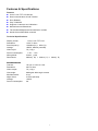
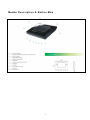
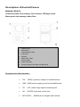
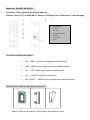
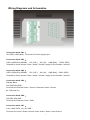
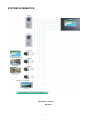
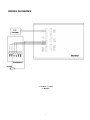
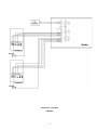
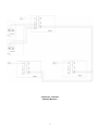
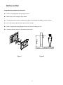
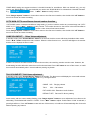
VIDEO INTERCOM SYSTEM USER MANUAL ES-V600 0 Contents Installation Guide ...................................................................................................................2 Features & Specifications......................................................................................................... 3 Descriptions of Monitor ............................................................................................................ 4 Descriptions of Doorbell/Camera............................................................................................. 4 Wiring Diagrams and Schematics............................................................................................ 7 SYSTEM SCHEMATICS ............................................................................................................. 8 WIRING DIAGRAMS................................................................................................................... 9 INSTALLATION ........................................................................................................................ 12 Operation Guide ......................................................................................................................14 System Settings......................................................................................................................... 15 Function Guide ........................................................................................................................ 17 1 Installation Guide 2 Features & Specifications Features Color 7-inch TFT LCD Screen Dual communication & Call Transfer Door Release Play TV/MUSIC Supports 2 cameras and 4 Monitors Monitor/Intercom/Broadcast Time/Volume/Brightness/Contrast/Color controls Hands free surface/flush mounted Technical Specifications: Display screen: color 7-inch TFT LCD Resolution: > 400 TV lines Scan frequency: Voltage: Video Input: 15,625Hz (H) 50Hz (V) 18VDC, 800mA (nominal) 75ς, 1Vp-p Power Consumption: 1.5w ∼12 w Wiring Mode: 4 wires,polar Dimensions: 260mm(W) 195mm(H) 44mm(D) Doorbell/Camera Camera: 1/3 inch or 1/4 inch color Resolution: Video output: 420 TV lines 75ς, 1Vp-p View angle: 68-degree wide-angle camera Min illumination: 0 Lux Night Vision: 3 LEDs (infrared) Voltage: Power Consumption: 12VDC 2w 3 Monitor D e s c r i p t i o n & B u t t o n M a p 4 Descriptions of Doorbell/Camera Model No.: ES-VC2 Surface-mounted, Zinc Housing, Color Camera, LED Night vision, Water-proof, Anti-sabotage, Name Plate 1. Camera Lens 2. Microphone 3. Indicator/Name Plate 4. Call button 5. Speaker 6. Night Vision LEDs 7. Screws Holes 8. 9. Cable Terminals Screw for fixing Face Plate and Main Body Descriptions for Cable terminals: PW: (RED)+ (positive) voltage for doorbell/camera GND:(BLK) power supply ground for doorbell/camera VD: (YEL) video image signal transmitting line AD: (WHITE) audio and control lines KEY1/KEY2: (BRWN) door lock/gate latch release 5 Model No.: ES-VBIT & ES-VCIT Surface or Flush mounted, Aluminium Housing, Pinhole Color (VC1T) or B/W (VB1T) Camera, LED Night vision, Water-proof, Anti-sabotage 1. Microphone 2. Camera 3. IR LEDs 4. Doobell/Call button 5. Speaker 6. 7. Screw Hole Cable Connection interface description: PW:(RED) + (positive) voltage for doorbell/camera GND:(BLK) power supply ground for doorbell/camera VD: (YEL) video image signal transmitting line AD: (WHITE) audio and control lines KEY1/KEY2: (BRWN) door lock/gate latch release interface ES-VBIT/VCIT Optional installation accessories: Above: Flush mount back-box, Wall bracket, Rain deflector cover 6 Wiring Diagrams and Schematics Connection block CN1: 18V (RED), GND (BLK):Terminals for Power Supply Input Connection block CN3: ,KEY1+(SDOOR1) (BRWN)、 VD1 (YEL)、 AU1 (W)、 GND (BLK) 、PWR1 (RED) Terminals for Power Unlock / Video / Audio / Ground / supply for the Doorbell / camera1. Connection block CN4: ,KEY1+(SDOOR1) (BRWN)、 VD1 (YEL)、 AU1 (W)、 GND (BLK)、PWR1 (RED) Terminals for Power Unlock / Video / Audio / Ground / supply for the Doorbell / camera1. Connection block CN5: Standby Block VD3,GND,AD3,GND: Terminals for Extension Audio / Ground / Extension Video / Ground J1: 75R jump line Connection block CN6: VD4,VD5,VD6,GND: Terminals for Extension Video / GND Connection block CN7: +18V, GND, DATA, AU, VD, GND: Terminals for Power+/ Power Ground / Data / Audio / Video / Video Ground 7 SYSTEM SCHEMATICS 2 Cameras, 2 Latches Monitors 8 WIRING DIAGRAMS 1 Camera, 1 Latch 1 Monitor 9 2 Cameras, 2 Latches 1 Monitor 10 2 Cameras, 2 Latches Multiple Monitors 11 INSTALLATION Single Monitor Installations Instruction: Refer to the appropriate wiring diagram above. Make sure you are using the right cables. Consider placement of item carefully with regard to user height and ability to reach controls. Run cable through bracket, then attach bracket to wall. Refer to appropriate wiring diagram above and connect cable(s) to unit. Install the indoor monitor on the wall as shown below. Figure 1 Figure 2 12 Single Doorbell Camera Installations Instruction: Carefully consider positioning of the doorbell camera. We recommend testing the position with the indoor station prior to making permanent attachment. Consider lighting factors and position of sun, and color/brightness of the background behind the visitor. These factors will affect video quality. Remember some of these factors may change during the day or season. NOTE: When the distance between indoor monitors and doorbells is less than 30 meters, you can use 22 gauge 4 conductor shielded cable. If distance is over 30 meters, please add one RG59 coaxial wire with 4 wire-shielded cable to ensure video stability. Video coaxial cable 4-core shielded cable 13 Operation Guide 14 System Settings – See MONITOR DESCRIPTION & BUTTON MAP At standby mode, press and hold “Image capture” button for 5 seconds to get into the set-up mode as below. 1st line: Chime Duration Time 2nd line: Character Add: Enable/Disable “DOOR1/DOOR2” on monitor screen) 3rd line: Main/Sub Multiple Monitor set up HOLD button 6 on MAIN or SUB for 3 seconds At this point, pressing “Image capture” button will move to the next value until Intercom/Main menu. Use “◄►” (button 5) to select Main or Sub. When enter main panel selection。When cursor is at MAIN status, press button two seconds and then you will enter the second menu interface: 1nd line: Setup doorbell active numbers 2rd line: Setup video extending channels numbers CHIME TIME SET: Chime Duration The default chime duration is 30 seconds. To adjust this time: When the curser flashes at the first character of date, keep pressing “Image capture” button to go to the chime duration setting. Press “◄►” button to adjust the chime time. The chime duration is from 10 – 90 seconds. CHAR ADD SET : At standby mode, press “Image capture” button to get into the main menu setting interface. Move the cursor to the 5th line, press “◄►” BUTTON to choose Enable or Disable. "Enable" will display the character “DOOR1” or “DOOR 2”. If choose “Disable”, the monitor screen will not display any characters. INTERCOM SUB or MAIN Set: If more than one monitor is installed, one monitor is set as “MAIN-1”. Additional monitors should be set as “SUB”. DOOR NUM: Doorbell channel active number function: 15 “DOOR NUM” setting can support maximum 2 doorbell channels for surveillance. With one doorbell only, you only need to set “DOOR NUM 1”. For two doorbells you need to set “DOOR NUM 2” to activate both 2 doorbell cameras. E.g. Press “◄►” button to modify number. Press “Image capture” button for 2 seconds to return to the first menu interface, then double click “off” button to turn off the screen and save the setting. CCTV NUM: CCTV surveillance channel number function: “CCTV NUM” means 4 cameras surveillance image setting, if you don’t need to monitor any camera image, set “CCTV NUM” as “0”. Press “◄►” button to modify number. The number showed on the screen is the total surveillance number. E.g. means 4 video channel has been activated. Press “Image capture” button for 2 seconds to return to the first menu interface, then double click “off” button to turn off the screen and save the setting. CHIME VOLUME SET : Chime Volume adjustment In standby mode, press “Answer /Monitor” button for 6 seconds, the blue screen will show the default chime mode. Press “◄►” button to adjust the chime volume. When the mute function is on, a red LED will light on the monitor and the screen displays the word “mute”. If there is a call from doorbell camera or other indoor monitor, the receiving monitor remains mute. However, the broadcasting function still works when the mute function activated. Press “off” button to turn off the screen, or it will be turned off automatically after 5 seconds without pressing any button. TALK VOLUME SET: Talk Volume adjustment In standby mode, press “Answer /Monitor” button for 6 seconds. The blue screen will display the current talk volume. Keep pressing this button to adjust the talk volume. E.g. Like figure below: CHIME VOL:Ringing volume TALK VOL:Call volume EXT-AUDIO VOL: Extension-Audio Volume DEFAULT SET:Recover Ex-factory setting At this mode, with the current setting flashing, press “Image capture” button to move adjustment from chime to the talk-setting. The defaulted talk volume is ”HIGH”. Press “◄►” button to adjust. If talk volume “LOW’ is selected, a green light will be on. Press “off” button to save and turn off the screen, or it will turn off automatically after 5 seconds without pressing any buttons. 16 Brightness/Contrast/Color: At standby mode, press “Answer /Monitor” button to display an image, press“◄►” button to adjust the Brightness/Contrast/Color for the image. At monitoring mode, press “◄►” button to adjust Brightness. Press “Image capture” button to move between Brightness, Contrast, Color Settings. Function Guide Call & Unlock Function When a visitor calls from the doorbell/camera, the visitor’s image shows on the monitor screen. Press “Answer /Monitor” button to stop the chime. 1) You now have 60 seconds default talking time. 2) During the 60 seconds talking period, you can decide to release the door or not for this visitor. Press and hold the “Unlock” key. The shortest unlock time is 1sec. The Green/Red Indicator will be on when the door is releasing. (Green Light for the Doorbell/Camera1. Red light for the Doorbell/Camera 2.) Door can only be released at answering mode. The door can not be released at any other mode for security reasons. (e.g. accidental pressing). Intercom Function In standby mode, press “Call transfer” button to initiate a transfer. The receiving monitors will chime until any monitor answers by pressing “Answer /Monitor” button. Call Transfer Function 1) Direct Transfer: To transfer the call to other monitors: Press “Call transfer” button on the monitor. All other monitors in the system will receive your call transferring message. Anyone can press the “Answer /Monitor” button on any other unit to talk with the visitor. 2 ) Broadcasting transfer When you answer the call, press “Call transfer” button and hold. The word “mute” will appear. During this time you may get a chance to ask another person if he/she would like to answer the visitor. Press “Call transfer” button again to get into the communication mode. Broadcasting Function In standby mode, press and hold “Call transfer” button for 2 seconds on any monitors to activate the broadcasting function, once the broadcasting function is activated, you can talk to all other indoor monitors. Monitoring function: Press and hold “Monitor” (BUTTON 1) on any monitor will view the outside images from the Doorbell/Camera. Green & Red lights will display for Camera 1 or 2 respectively. The default monitoring time is 30sec. When monitor extension 4 17 camera channels,press button1 to turn off the screen. At standby mode, keep pressing button1 to monitor door1, door2, audio/video channel1, extension video channel1, extension video channel2, extending video channel3. Audio/Video Function In standby mode, press BUTTON 2 on any monitors 3 times to activate the Audio/Video function for listening music or watching TV, or monitoring the baby-rooms. CARE INSTRUCTIONS 1) 2) 3) 4) 5) Always use the recommended cables. To clean, use a damp cloth and gently wipe lens surfaces outwards. Do not use cleaning fluids or solvents. Image distortion may occur if your equipment is mounted too close to magnetic field e.g. Microwaves, TV, Audio equipment or speakers. The Doorbell/Camera should be fitted with an approved weather shield if the position chosen is in direct sunlight, or in contact with rain, snow or irrigation sprinkler systems. Do not open the case beyond the point necessary to install as described in this manual. Doing so may void your warranty. There are NO USER SERVICEABLE PARTS INSIDE. Eclipse CCTV Corp. Reserves the Right to Make Changes at Any Time to This Product and This Manual Without Prior Notice This product requires installation by qualified personnel. Eclipse CCTV Corp. accepts no responsibility whatsoever for any damage to personnel or property caused by incorrectly installing or using this product, or damage or injury due to installation by unqualified personnel. 18


![Fio 2.0 UM ECU [ENG]](http://vs1.manualzilla.com/store/data/005638068_1-6dee15c8bb797972f1fa6aeeeee54189-150x150.png)