1
F-15-108-A
May, 1997
ESP-400
CUTTING POWER SOURCE
P/N 33518
PANEL
REMOTE
CURRENT CONTROL
MAINTENANCE MANUAL
These INSTRUCTIONS are for experienced operators. If you are not fully familiar with the principles of operation
and safe practices for electric welding equipment, we urge you to read our booklet, "Precautions and Safe
Practices for Arc Welding, Cutting, and Gouging", Form 52-529. Do NOT permit untrained persons to install,
operate, or maintain this equipment. Do NOT attempt to install or operate this equipment until you have read
and fully understand these instructions. If you do not fully understand these instructions, contact your supplier
for further information. Be sure to read the Safety Precautions (Section I) before installing or operating this
equipment.
Be sure this information reaches the operator.
You can get extra copies through your supplier.
USER RESPONSIBILITY
This equipment will perform in conformity with the description thereof contained in this manual and accompanying
labels and/or inserts when installed, operated, maintained and repaired in accordance with the instructions provided. This equipment must be checked periodically. Defective equipment should not be used. Parts that are
broken, missing, worn, distorted or contaminated should be replaced immediately. Should such repair or replacement become necessary, the manufacturer recommends that a telephone or written request for service advice be
made to the Authorized Distributor from whom purchased.
This equipment or any of its parts should not be altered without the prior written approval of the manufacturer. The
user of this equipment shall have the sole responsibility for any malfunction which results from improper use, faulty
maintenance, damage, improper repair or alteration by anyone other than the manufacturer or a service facility
designated by the manufacturer.
TABLE OF CONTENTS
SECTION
PARAGRAPH
TITLE
PAGE
Section 1
1.1
1.2
1.3
1.4
1.5
1.6
1.7
1.8
Safety ....................................................................................................................... 1-1
Introduction ............................................................................................................... 1-1
General ..................................................................................................................... 1-1
Fire and Explosion .................................................................................................... 1-2
Electrical Shock ........................................................................................................ 1-2
Fumes and Gases .................................................................................................... 1-3
Equipment Maintenance ........................................................................................... 1-3
Cylinders ................................................................................................................... 1-4
References ............................................................................................................... 1-4
Section 2
2.1
2.2
2.3
2.4
Description .............................................................................................................. 2-1
Introduction ............................................................................................................... 2-1
Description ................................................................................................................ 2-1
Cool-Down Periods ................................................................................................... 2-2
Volt-Ampere Curves .................................................................................................. 2-2
Section 3
3.1
3.2
3.3
3.4
Maintenance ............................................................................................................ 3-1
General ..................................................................................................................... 3-1
Cleaning .................................................................................................................... 3-1
Lubrication ................................................................................................................ 3-1
Testing and Replacing Bridge Assembly Components .............................................. 3-1
Section 4
4.1
4.2
Troubleshooting ..................................................................................................... 4-1
General ..................................................................................................................... 4-1
Troubleshooting Guide .............................................................................................. 4-1
Section 5
5.1
Replacement Parts .................................................................................................. 5-1
General ..................................................................................................................... 5-1
2
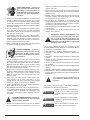
SAFETY PRECAUTIONS
WARNING: These Safety Precautions are for
your protection. They summarize precautionary information from the references listed in
Additional Safety Information section. Before
performing any installation or operating procedures, be
sure to read and follow the safety precautions listed below
as well as all other manuals, material safety data sheets,
labels, etc. Failure to observe Safety Precautions can result
in injury or death.
5. Do not use equipment beyond its ratings. For example,
overloaded welding cable can overheat and create a fire
hazard.
6. After completing operations, inspect the work area to
make certain there are no hot sparks or hot metal which
could cause a later fire. Use fire watchers when necessary.
7. For additional information, refer to NFPA Standard 51B,
"Fire Prevention in Use of Cutting and Welding Processes", available from the National Fire Protection Association, Batterymarch Park, Quincy, MA 02269.
PROTECT YOURSELF AND OTHERS -Some welding, cutting, and gouging
processes are noisy and require ear
protection. The arc, like the sun, emits
ultraviolet (UV) and other radiation and
can injure skin and eyes. Hot metal can cause burns.
Training in the proper use of the processes and equipment is essential to prevent accidents. Therefore:
ELECTRICAL SHOCK -- Contact with live
electrical parts and ground can cause
severe injury or death. DO NOT use AC
welding current in damp areas, if movement is confined, or if there is danger of
falling.
1. Always wear safety glasses with side shields in any work
area, even if welding helmets, face shields, and goggles
are also required.
2. Use a face shield fitted with the correct filter and cover
plates to protect your eyes, face, neck, and ears from
sparks and rays of the arc when operating or observing
operations. Warn bystanders not to watch the arc and
not to expose themselves to the rays of the electric-arc
or hot metal.
3. Wear flameproof gauntlet type gloves, heavy long-sleeve
shirt, cuffless trousers, high-topped shoes, and a welding helmet or cap for hair protection, to protect against
arc rays and hot sparks or hot metal. A flameproof apron
may also be desirable as protection against radiated
heat and sparks.
4. Hot sparks or metal can lodge in rolled up sleeves,
trouser cuffs, or pockets. Sleeves and collars should be
kept buttoned, and open pockets eliminated from the
front of clothing
5. Protect other personnel from arc rays and hot sparks
with a suitable non-flammable partition or curtains.
6. Use goggles over safety glasses when chipping slag or
grinding. Chipped slag may be hot and can fly far.
Bystanders should also wear goggles over safety glasses.
1. Be sure the power source frame (chassis) is connected
to the ground system of the input power.
2. Connect the workpiece to a good electrical ground.
3. Connect the work cable to the workpiece. A poor or
missing connection can expose you or others to a fatal
shock.
4. Use well-maintained equipment. Replace worn or damaged cables.
5. Keep everything dry, including clothing, work area, cables,
torch/electrode holder, and power source.
6. Make sure that all parts of your body are insulated from
work and from ground.
7. Do not stand directly on metal or the earth while working
in tight quarters or a damp area; stand on dry boards or
an insulating platform and wear rubber-soled shoes.
8. Put on dry, hole-free gloves before turning on the power.
9. Turn off the power before removing your gloves.
10. Refer to ANSI/ASC Standard Z49.1 (listed on next page)
for specific grounding recommendations. Do not mistake
the work lead for a ground cable.
ELECTRIC AND MAGNETIC FIELDS —
May be dangerous. Electric current flowing through any conductor causes localized Electric and Magnetic Fields
(EMF). Welding and cutting current creates EMF around welding cables and
welding machines. Therefore:
FIRES AND EXPLOSIONS -- Heat from
flames and arcs can start fires. Hot slag
or sparks can also cause fires and explosions. Therefore:
1. Remove all combustible materials well away from the
work area or cover the materials with a protective nonflammable covering. Combustible materials include wood,
cloth, sawdust, liquid and gas fuels, solvents, paints and
coatings, paper, etc.
2. Hot sparks or hot metal can fall through cracks or
crevices in floors or wall openings and cause a hidden
smoldering fire or fires on the floor below. Make certain
that such openings are protected from hot sparks and
metal.“
3. Do not weld, cut or perform other hot work until the
workpiece has been completely cleaned so that there
are no substances on the workpiece which might produce flammable or toxic vapors. Do not do hot work on
closed containers. They may explode.
4. Have fire extinguishing equipment handy for instant use,
such as a garden hose, water pail, sand bucket, or
portable fire extinguisher. Be sure you are trained in its
use.
1. Welders having pacemakers should consult their physician before welding. EMF may interfere with some pacemakers.
2. Exposure to EMF may have other health effects which are
unknown.
3. Welders should use the following procedures to minimize
exposure to EMF:
A. Route the electrode and work cables together. Secure
them with tape when possible.
B. Never coil the torch or work cable around your body.
C. Do not place your body between the torch and work
cables. Route cables on the same side of your body.
D. Connect the work cable to the workpiece as close as
possible to the area being welded.
E. Keep welding power source and cables as far away
from your body as possible.
11/95
3
FUMES AND GASES -- Fumes and
gases, can cause discomfort or harm,
particularly in confined spaces. Do
not breathe fumes and gases. Shielding gases can cause asphyxiation.
Therefore:
2.
3.
1. Always provide adequate ventilation in the work area by
natural or mechanical means. Do not weld, cut, or gouge
on materials such as galvanized steel, stainless steel,
copper, zinc, lead, beryllium, or cadmium unless positive
mechanical ventilation is provided. Do not breathe fumes
from these materials.
2. Do not operate near degreasing and spraying operations. The heat or arc rays can react with chlorinated
hydrocarbon vapors to form phosgene, a highly toxic
gas, and other irritant gases.
3. If you develop momentary eye, nose, or throat irritation
while operating, this is an indication that ventilation is not
adequate. Stop work and take necessary steps to improve ventilation in the work area. Do not continue to
operate if physical discomfort persists.
4. Refer to ANSI/ASC Standard Z49.1 (see listing below)
for specific ventilation recommendations.
4.
5.
6.
perform any electrical work unless you are qualified to
perform such work.
Before performing any maintenance work inside a power
source, disconnect the power source from the incoming
electrical power.
Maintain cables, grounding wire, connections, power cord,
and power supply in safe working order. Do not operate
any equipment in faulty condition.
Do not abuse any equipment or accessories. Keep
equipment away from heat sources such as furnaces, wet
conditions such as water puddles, oil or grease, corrosive
atmospheres and inclement weather.
Keep all safety devices and cabinet covers in position and
in good repair.
Use equipment only for its intended purpose. Do not
modify it in any manner.
ADDITIONAL SAFETY INFORMATION -- For
more information on safe practices for electric arc welding and cutting equipment, ask
your supplier for a copy of "Precautions and
Safe Practices for Arc Welding, Cutting and
Gouging", Form 52-529.
The following publications, which are available from the
American Welding Society, 550 N.W. LeJuene Road, Miami,
FL 33126, are recommended to you:
1. ANSI/ASC Z49.1 - "Safety in Welding and Cutting"
2. AWS C5.1 - "Recommended Practices for Plasma Arc
Welding"
3. AWS C5.2 - "Recommended Practices for Plasma Arc
Cutting"
4. AWS C5.3 - "Recommended Practices for Air Carbon Arc
Gouging and Cutting"
5. AWS C5.5 - "Recommended Practices for Gas Tungsten
Arc Welding“
6. AWS C5.6 - "Recommended Practices for Gas Metal Arc
Welding"“
7. AWS SP - "Safe Practices" - Reprint, Welding Handbook.
8. ANSI/AWS F4.1, "Recommended Safe Practices for Welding and Cutting of Containers That Have Held Hazardous
Substances."
CYLINDER HANDLING -- Cylinders, if
mishandled, can rupture and violently
release gas. Sudden rupture of cylinder, valve, or relief device can injure or
kill. Therefore:
1. Use the proper gas for the process and use the proper
pressure reducing regulator designed to operate from
the compressed gas cylinder. Do not use adaptors.
Maintain hoses and fittings in good condition. Follow
manufacturer's operating instructions for mounting regulator to a compressed gas cylinder.
2. Always secure cylinders in an upright position by chain
or strap to suitable hand trucks, undercarriages, benches,
walls, post, or racks. Never secure cylinders to work
tables or fixtures where they may become part of an
electrical circuit.
3. When not in use, keep cylinder valves closed. Have
valve protection cap in place if regulator is not connected. Secure and move cylinders by using suitable
hand trucks. Avoid rough handling of cylinders.
4. Locate cylinders away from heat, sparks, and flames.
Never strike an arc on a cylinder.
5. For additional information, refer to CGA Standard P-1,
"Precautions for Safe Handling of Compressed Gases in
Cylinders", which is available from Compressed Gas
Association, 1235 Jefferson Davis Highway, Arlington,
VA 22202.
This symbol appearing throughout this manual
means Attention! Be Alert! Your safety is
involved.
The following definitions apply to DANGER, WARNING,
CAUTION found throughout this manual:
Used to call attention to immediate hazards which, if not avoided, will result in
immediate, serious personal injury or loss
of life.
EQUIPMENT MAINTENANCE -- Faulty or improperly maintained equipment can cause
injury or death. Therefore:
Used to call attention to potential hazards which could result in personal injury
or loss of life.
1. Always have qualified personnel perform the installation, troubleshooting, and maintenance work. Do not
Used to call attention to hazards which
could result in minor personal injury.
4
SECTION 2
2.1
DESCRIPTION
Introduction
The ESP-400 Plasma Power Source is designed for high speed plasma cutting applications. It is normally used with
equipment such as the ESAB Smart Plasma System (ESP). For cutting currents beyond the rating of the ESP-400,
parallel operation of these units is permissible. It is also possible to operate in parallel (see ref on figure 5-2) with the
ULTRA-LIFE 300 or ESP-600 cutting Power Source. For additional operating data and electrical characteristics of this
machine, refer below to Table 2-1, ESP-400 Specifications.
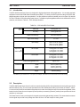
TABLE 2-1. ESP-400 SPECIFICATIONS
Rated
Output
Input Current
@
Rated Output
100% Duty
400 A @ 200 V dc
50% Duty*
500 A @ 200 V dc
Output Current Range
100 to 500 Amperes
Open Circuit Voltage
417 V dc
Input Voltage
460 V ac, 60 Hz, 3-phase
380 V ac, 50 Hz, 3-phase
415 V ac, 50 Hz, 3-phase
400 A Output
156 A @ 460 V ac, 60 Hz
173 A @ 415 V ac, 50 Hz
189 A @ 380 V ac, 50 Hz
500 A Output
195 A @ 460 V ac, 60 Hz
216 A @ 415 V ac, 50 Hz
237 A @ 380 V ac, 50 Hz
Power Factor @ Rated Load
Dimensions
Approx. 75%
Width
Depth
Height
36.75 in. (933.5 mm)
43.50 in. (1105 mm)
31.00 in. (787.4 mm)
Weight
1830 lbs (830 kg)
*The 50% duty cycle is based on a 1-hour period; for example, 30 minutes "on" and 30 minutes "off" with fan running.
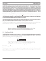
2.2
Description
The ESP-400 Plasma Power Source is a silicon controlled rectifier (SCR), three-phase transformer/rectifier type dc unit
with solid state circuitry. The unit can be operated from 100 to 500 amperes at duty cycles shown in Table 2-1, above.
A current control Panel-Remote Switch determines the location from which the output current will be regulated: either
locally from the Power Source front panel (Panel position) or remotely ("Remote" position) from a precision 0-10 volt
reference (V ref) signal.
The Power Source circuitry receiving the V ref signal is electrically (galvanically) isolated. This means that the common
for this signal may be tied to any voltage less than 150 V ac or dc with respect to earth ground.
5
SECTION 2
DESCRIPTION
The ESP-400 is powered by a three-phase main transformer which combines with solid state control to provide voltamperes curve output characteristics required for plasma cutting (see figure 2-1). A three-phase full wave SCR and
diode bridge rectifier are used to convert the ac output current from the transformer to dc cutting current, and also control
the output current through the SCRs. A network of integrally-mounted capacitors and resistors provide transient and
high frequency voltage protection to the rectifier SCRs and diodes. Protection for the main transformer bridge rectifier
and the inductor is provided by over-temperature thermal switches which interrupt power in the event of an overheating
condition and automatically reset when the components have cooled to their normal operating temperature. Filtering
of the dc output current is provided by an inductor.
The solid state circuitry of the ESP-400 produces stable cutting current and eliminates changes in output current as
components heat up and/or if input line voltage changes within +10% of nominal. In addition, the control circuit has builtin line voltage compensation, which corrects the output of the Power Source for various changes in the input line voltage.
This feature ensures consistency in cutting conditions even if line voltage changes. Actual load current and voltage
are indicated by an ammeter and voltmeter mounted on the front panel.
Connections for control functions from the Flow Control assembly are made from a 19-pin plug receptacle on the front
panel. This receptacle provides connection for auxiliary 115 volts out, remote current control.
The Power Source is designed for ease in moving and handling. Sufficient clearance and reinforcement at its base
permits lifting with a fork lift truck; or raising with a crane or hoist using the lifting rings in the top cover.
When moving the power source, always use both lifting rings in order to keep
the power source level, otherwise serious internal damage may occur.
2.3
Cool-Down Periods
The ESP-400 Power Source has two cool-down periods: 1) 100% duty @ 400 amperes (400 amperes may be applied
continuously without a cool-down period); 2) 50% duty - 1 hour base period @ 500 amperes (500 amperes may be
applied continuously for 30 minutes followed by a 30 minute cool-down period with fan motor running. This cool-down
period is proportionately less for shorter operating periods).
Output ratings are designed and based on an unobstructed supply of cooling
air flow over its internal components. DO NOT USE FILTERS ON THIS UNIT.
Periodically blow out dirt accumulations, using low pressure air.
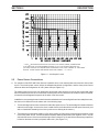
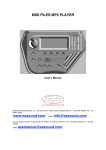
2.4 Volt-Ampere Curves
The volt-ampere curves show the output voltage available at any given output current for the various current control
(or V ref signals from CNC control) settings. Values for settings other than those shown in figure 2-1, fall between the
Minimum and Maximum curves shown.
6
SECTION 2
DESCRIPTION
THE VREF DESIGNATION SHOWN ON THE TYPICAL V/A CURVES (ABOVE) CORRESPONDS
TO AN ABSOLUTE VOLTAGE REFERENCE SIGNAL (0 TO 10 VOLT RANGE) FROM THE CNC
(CUTTING) CONTROL THAT ESTABLISHES THE PRECISE OUTPUT ARC CURRENT OF THE POWER
SOURCE. THESE CURVES ARE DERIVED FROM THE FORMULA I ARC = 50 VREF
Figure 2-1. Volt-Ampere Curves
2.5
Power Source Connections
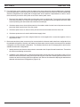
A. For operation of two ESP-400 Power Sources in parallel, there is one master power source and one slave power
source. The master power source utilizes the standard transformer configuration, and the slave power source
utilizes an alternate configuration for 180° phase shift (see Figure 2-2).
The master power source is the one utilizing the 19-conductor cable from the front of the flow control and is also
the one to which the pilot arc wire is connected. The slave power source utilizes the 19-conductor cable, P/N 33940,
connected to the designated receptacle at the back of the flow control.
In addition to reconnecting the main transformer and considerations of connecting the flow control and pilot arc wire,
the slave unit is different from the master unit in the following ways:
1. The boost bridge fuses must be removed from the slave power source. The boost bridge is located on the base
under the main bridge. Access to the fuses is made from the left side with the left side panel removed. (Left
side is viewed while standing in front of the power source looking at the meters.)
2. The black wire connecting the negative of C21 to the positive of C22 must be removed from the positive of C22
in the slave power source. The wire should be looped by attaching both ends to the negative of C21. This will
eliminate the concern of the loose end shorting to other conductors. (C21 and C22 are the two large capacitors
located on the base near the input power strain relief. (See Figure 5-2.)
7
DESCRIPTION
SECTION 2
B. For single Power source operation, either the master or the slave unit may be used, provided items 1. through 5.
below are addressed. It is not necessary to reconnect the main transformer in the slave unit. Both the standard and
alternate configurations work equally well for single power source operation. Implementation of items 4. and 5.
below effectively convert the slave power source into a master power source.
1. Disconnect the negative output cable from the power source not being used. To prevent the removed cable
from being electrically hot when the other power source is activated, remove the opposite end of the cable
from the plumbing box and insulate both ends with electrical tape.
2. If the slave power source is used, disconnect the 19-conductor cable from the front of the power source and
plug in the cable from the front of the flow control.
3. If the slave power source is used, move the pilot arc wire from the master unit to the slave unit.
4. If the slave power source is used, install the boost supply fuses.
5. If the slave power source is used, using the black wire on the negative C21, connect the negative of C21 to
the positive of C22.
C. Both master and slave power sources may be reconnected to the alternate main transformer configuration from
the standard configuration. Likewise, both master and slave power sources may be reconnected to the standard
configuration from the alternate configuration. The following instructions are for changing both to and from the
standard and alternate configurations.
1. Identify the three wires from the main contactor connected to the H1 taps of the main transformer. These wires
will not be moved during reconnection.
2. In addition to the contactor wires, each transformer primary has two other wires connected to each coil. Find
these wires and reverse them, taking care to work with only one coil at a time. Working with more than one coil
at a time can result in mixing up wires from different coils. Refer to the schematics depicting the standard and
alternate main transformer configurations (Figure 2-2).
8
DESCRIPTION
SECTION 2
TO CHANGE TO 380 V OR 415 V INPUT:
On the main transformer (T1) - both master and slave:
For 415 V input, move the wire from H4 to H3 for all three coils.
For 380 V input, move the wire from H4 to H2 for all three coils.
On the control transformer (T2):
For 415 V input, move the brown wire on H9 to H6.
For 380 V input, move the brown wire on H9 to H5.
Figure 2-2. Master and Slave Configurations
9
MAINTENANCE
SECTION 3
3.1 General
If this equipment does not operate properly, stop work immediately and investigate the cause of the malfunction.
Maintenance work must be performed by an experienced person, and electrical work by a trained electrician. Do not
permit untrained persons to inspect, clean, or repair this equipment. Use only recommended replacement parts.
TO PREVENT ACCIDENTAL ELECTRIC SHOCK, BE SURE THAT THE WALL
DISCONNECT SWITCH OR CIRCUIT BREAKER IS OPEN BEFORE ATTEMPTING ANY INSPECTION OR WORK INSIDE THE POWER SOURCE.
3.2 Cleaning
Since there are no moving parts (other than the fan) in the power source, maintenance consists mainly of keeping the
interior of the cabinet clean. Periodically, remove the cover from the cabinet and blow accumulated dust and dirt from
the air passages and the interior components, using clean, dry low pressure air. It is imperative that the air passages
to the interior of the unit be kept free of dirt accumulation to ensure adequate circulation of cooling air, especially over
the extrusion fins of bridge rectifier. This unit is NOT designed to be used with air filters of any kind. Any obstruction
to the free flow of cooling air may damage the machine and void the warranty. The frequency of cleaning needed
depends upon the amount of dirt that is drawn into the unit.
3.3 Lubrication
Fan motors with oil tubes located on the side of the motor require lubrication after one year of service. Motors without
oil tubes are permanently lubricated and should not require any attention.
3.4 Testing and Replacing Bridge Assembly Components
The silicon diodes and SCRs used in the Power Source are devices which allow current to flow in only one direction.
They block current flow in the other direction. The diodes and SCRs used in this Power Source are designed to provide
long trouble-free operation; however, should a failure occur, they require replacement. The location and replacement
parts data for the diodes and SCRs are shown in figures 5-1 through 5-4.
If after troubleshooting, the "trouble symptom" appears to be in the Bridge or Boost Bridge (BR, BBR) networks: the
following three-part procedure can be used to determine the faulty component(s): Visual Analysis, Component Group
Testing, and Individual Component/Isolation Testing.
If component repair or replacement is necessary, the Boost Bridge components are readily accessible in the power
source; however, to service Main Bridge components, removing the bridge assembly is recommended.
Before removing the main bridge assembly for servicing, carefully tag (identify) all interconnecting wires and bus connections to facilitate proper reinstallation. Also, refer to the diagrams and illustrations in the back of this book.
10
SECTION 3
A.
MAINTENANCE
Visual Analysis For Defective BR/BBR Components.
1.
Remove top and left side panels of Power Source. Inspect the 500 A BR fuse links (F3 and F4) mounted in
the Main Transformer secondary bus bars to see if they have blown. If not blown, check the 30 A BBR
cartridge fuses (F1 and F2) with an ohmmeter to determine if they are open.
2.
If either or both of the fuses protecting its respective bridge assembly are open, it's a sign that one or more
of the diodes or SCRs in that particular bridge may be shorted.
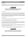
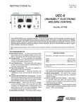
3.
Refer to figure 3-1 for the makeup of a fuse and information to prevent hardware from loosening due to thermal
cycling.
NOTE
Figure 3-1 depicts one end of one fuse. The other end is the same.
FUSE
BUS BAR
NOTES 1 & 2
NOTE 4
NOTE 3
FUSE SUPPORT
Figure 3-1. Fuse Assembly
NOTES:
1.
2.
3.
4.
4.
B.
Fuse link must be in direct contact with copper bus bar (no hardware in between).
Apply electrical joint compound between fuse link and bus bar.
Wire brush bus bar and fuse link at mating point prior to installing to prevent
overheating and to ensure good electrical contact.
Any 1/4-inch bolt or screw is usable if threaded completely to head or within 1/4 inch
of head. A 1/4-inch threaded rod may be substituted for bolt or screw.
It is critical that a space (one full turn) remain between nuts.
Check for cracked or broken ceramic around each diode pigtail of SCR body. If cracked, it's a sign of a shorted
diode or SCR. When the larger diodes or SCRs fail, they most commonly fail shorted.
Testing Main Bridge Rectifier (MBR) Assembly.
The Main Bridge essentially contains three groups of components to be tested: Power Diodes D4, D5, and D6;
Freewheeling Diode D7; and SCRs 4, 5, and 6. The group testing sequence does not require electrical isolation;
however, to determine the specific faulty component in a group, some form of isolation may be required as follows:
1.
Checking Power Diode Group D4, D5 and D6.
(a)
If fuse links F3 and F4 are not blown, use an ohmmeter set at its lowest resistance scale and check
the diode group as described in step 1.(c). Checking any one diode within the group will determine
if the group is good or if a shorted condition exists. If there is a short, you must electrically isolate to
11
SECTION 3
MAINTENANCE
determine the specific component. Electrical isolation is accomplished by unbolting the pigtail of
the diode being tested.
(b)
If one or more fuse links (F3/F4) are blown, the diodes must be isolated and checked individually.
(c)
Ohmmeter check of diodes (group or individual).
NOTE
Some analog meters and most digital meters will read similarly high both before
and after reversing the meter leads when testing good diodes and SCRs.
2.
1
Place one test probe on NEG heatsink (diode stud) and the other probe to each diode pigtail's
SCR heatsink. Note the resistance readings obtained. All three readings should be similar
(high or low).
2
Reverse the test probes and recheck the diodes. Note each resistance reading. All three
readings should be similar; but, opposite of those noted in the first reading.
3
Diodes are good if they test high in one direction and low in the opposite direction. Diodes
are bad if the resistance readings are low in both directions. High readings in both directions
when using a digital ohmmeter indicates a good diode.
4
Diodes are bad when they show no, or very low, resistance in both directions indicating they
are shorted. Although it is possible for power rectifier diodes to fail "open", such failures are
rare, particularly for the larger diodes. In the vast majority of cases, a high resistance reading
in either or both directions indicate a good diode.
Checking Freewheeling Diode D7.
This diode must be checked in the circuit using the same procedures outlined in steps 1.(a), 1.(b), and
1.(c). If the diode tests "good", nothing else need be done; however, if the diode tests "bad", you must
disconnect its pigtail and retest it for verification.
3.
Checking SCR Group SCR 4, 5 and 6.
NOTE
Before proceeding with the following SCR tests, all diodes D4, 5, 6 and 7 should
have been checked, and defective (shorted) diodes electrically isolated.
(a)
If fuse links F3 and F4 are not blown and are still connected to the bridge heatsink, use an ohmmeter
set to its lowest resistance scale and check the SCR group as described in step 3.(c). Checking
any one SCR within the group will determine if the group is good or if a shorted condition exists.
If there is a short, you must electrically isolate to determine the specific faulty component, see step
3.(d).
(b)
If one or more fuse links (F3/F4) are blown, the SCRs must be isolated and checked individually.
Refer to step 3.(d).
12
MAINTENANCE
SECTION 3
(c)
(d)
C.
Ohmmeter check of SCRs (group or individual).
1.
Place one test probe on the POS heatsink (same as the shunt) and touch the other test probe
to each of the SCR's anode heatsinks. The resistance reading across each SCR should be 1000
(1K) ohms or higher.
2.
Reverse the test probes and repeat the check. Again, the resistance reading across each SCR
should be 1000 (1K) ohms or higher.
3.
SCRs are bad if they show no or very low resistance reading in either direction.
If the diagnosis indicates a defective SCR within the group, you must disconnect fuses F3 and F4 to
electrically isolate the SCRs (assuming all diodes D4, 5, 6, 7 have checked good, or defective diodes
previously isolated), and repeat the ohmmeter tests in steps 1, 2, and 3 above for each SCR.
Testing Boost Bridge Rectifier (BBR) Assembly.
1.
Remove the 30 ampere fuses, F1 and F2, to electrically isolate the diodes of the BBR assembly from each
other and the SCRs of the BBR assembly from each other. (Its always good practice to check the fuses for
continuity to make sure whether they are good or bad. Use ohmmeter set to RX1 scale.)
2.
Check diodes (D1, 2 and 3) with an ohmmeter set to the RX1 scale, as follows:
NOTE
Some analog meters and most digital meters will read similarly high both before and
after reversing the meter leads when testing good diodes and SCRs.
3.
(a)
Place one test probe on the NEG heatsink (diode stud) and the other probe to each diode pigtails SCR
heatsink. Note the resistance reading obtained. All three readings should be similar (high or low).
(b)
Reverse the test probes and recheck the diodes. Note each resistance reading. All three readings
should be similar; but, opposite of those noted in the first reading.
(c)
Diodes are good if they test high in one direction and low in the opposite direction. Diodes are bad if
the resistance readings are low in both directions. High readings in both directions when using a digital
ohmmeter indicates a good diode.
(d)
Diodes are bad when they show no, or very low, resistance in both directions indicating they are
shorted. Although it is possible for power rectifier diodes to fail "open", such failures are rare,
particularly for the larger diodes. In the vast majority of cases, a high resistance reading in either or
both directions indicate a good diode.
Check the SCRs (SCR1, 2 and 3) with an ohmmeter set to RX1 or RX100 scale, as follows:
(a)
Place one test probe on the POS heatsink (SCR pigtails) and the other probe to each SCRs stud
heatsink. All three readings should show a high resistance of 1000 (1K) ohms or higher.
(b)
Reverse the test probes and recheck the SCRs. Again, all three readings should show a high
resistance similar to the first test.
13
MAINTENANCE
SECTION 3
(c)
D.
An SCR is bad if it shows no, or very low resistance, in either direction.
Replacing Faulty SCRs and Diodes.
1.
Make sure that heatsink mounting surfaces are cleaned before replacing faulty components.
2.
For diodes and SCRs, coat mounting surfaces with Alcoa No. 2 EJC Electrical Joint Compound.
3.
Clamping procedure for Main Bridge SCRs (4, 5 and 6).
4.
(a)
Tighten the SCR clamp nuts by hand until fingertight.
(b)
Then, using a wrench, alternately tighten each nut 1/4 turn at a time until the spring indicator on the
clamp assembly shows 1000-1500 pounds, or 1 to midway between 1 and 2 on the indicator.
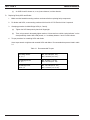
Torque procedure for remaining SCRs and diodes.
Use a torque wrench to tighten stud mounted SCRs and diodes. Recommended torques are listed in table
3-1.
Table 3-1. Recommended Torques
Main Bridge Diodes
D4, 5, 6, 7
Min., 275 in-lbs (23 ft · lbs)
Max., 325 in-lbs (27 ft · lbs)
Boost Bridge Diodes
D1, 2, 3
Min., 20 in-lbs (1.7 ft · lbs)
Max., 30 in-lbs (2.5 ft · lbs)
Boost Bridge SCR's
SCR1, 2, 3
Min., 125 in-lbs (10.4 ft · lbs)
Max., 150 in-lbs (12.5 ft · lbs)
14
SECTION 4
TROUBLESHOOTING
4.1 General
DISCONNECT PRIMARY POWER AT WALL SWITCH, OR CIRCUIT BREAKER,
BEFORE ATTEMPTING INSPECTION OR WORK INSIDE OF THE POWER
SOURCE.
If the Power Source is operating improperly, the following troubleshooting information may be used to locate the source
of the trouble.
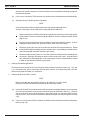
Check the problem against the symptoms in the following troubleshooting guide. The remedy for the problem may be
quite simple. If the cause cannot be quickly located, open up the unit and perform a simple visual inspection of all the
components and wiring. Check for proper terminal connections, loose or burned wiring or components, blown fuses,
bulged or leaking capacitors, or any other sign of damage or discoloration.
4.2 Troubleshooting Guide
A.
B.
C.
Fan Not Running.
1.
No input power. Check main line (customers) switch fuses.
2.
Defective control transformer. Check for continuity.
3.
Fan motor defective. Check motor and leads, and replace if necessary.
No Output.
1.
No incoming three-phase power. Wall disconnect switch may be open, or fuse(s) blown.
2.
Poor connections at output terminals. Tighten or replace connections.
3.
Main contactor not energized:
a.
Thermal overload (TS1, 2, 3, 4, or 5) device(s) tripped.
b.
Contactor coil defective.
c.
Missing "start" signal.
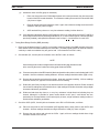
Low Open Circuit Voltage (O.C.V.).
Normal O.C.V. is 417 volts for a nominal 460 volt line input. If your actual line voltage is running lower, your O.C.V. will
be proportionately lower; if its running higher, the O.C.V. will be proportionately higher. Regardless of the range, so
long as O.C.V. is available it means that the main contactor (K1) is energized. However, if the voltage is approximately
300, its a sign that youre only receiving your open circuit voltage from the Main Bridge Rectifier. This indicates that
the Boost Bridge Rectifier is not supplying 417 volts.
1.
Boost Bridge fuses F1 and/or F2 blown. (Fuse replacement specifications are critical -- only use 30 ampere,
250 volt, slo-blo or time-delay fuses; such as, Buss No. FNW30, Shawmut No. TRM30, or Factory
replacements.)
15
TROUBLESHOOTING
SECTION 4
D.
2.
Faulty SCRs or diodes in Boost Bridge assembly. Check per Section 3, paragraph 3.4, steps A and C.
3.
SCR logic board defective. Replace board.
No Current Control or Erratic Output Current (O.C.V. is okay).
1.
2.
E.
F.
No current control -- none at all, fixed, or all out.
a.
Missing power or blown fuse links in Main or Boost Bridges.
b.
Defective SCR board.
c.
Defective constant current (CC) board.
d.
If current remains fixed at around 500 amperes (in Panel position), the bottom of the current control
potentiometer (R28) may not be connected. This results in applying +10 volts straight into CC board.
e.
Missing V ref signal from remote source. Check voltage from pins P1-2 to P1-1 on CC board for V
ref signal.
Erratic current control.
a.
Defective current control potentiometer (R28) (panel and/or remote location).
b.
Defective remote control switch (SW1). Check continuity.
Limited Output Current.
1.
Single phasing resulting from blown fused link(s) F3 and/or F4, and/or defective SCR(s) or diodes in Main
Bridge. Check per Section 3, paragraph 3.4 steps A, B, or D.
2.
Defective SCR board, that is not gating one of the Main Bridge SCRs.
3.
Insufficient V ref signal (less than 2.000 V).
Short (Torch) Tip Life -- Double Arcing.
1.
Low open circuit voltage. Refer to symptom C.
2.
Defective SCR board.
3.
Defective CC board.
4.
Defective SCR in Main Bridge.
5.
Pilot Arc Work connection not properly made. Refer to ESP manual.
16
SECTION 4
D-33071-B
17
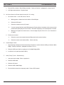
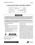
TROUBLESHOOTING
Figure 4-1. ESP-400 Power Source Schematic Diagram
SECTION 4
D-33072-B
18
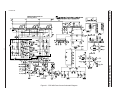
TROUBLESHOOTING
Figure 4-2. ESP-400 Power Source Wiring Diagram (Sheet 1 of 2)
SECTION 4
D-33072-B
19
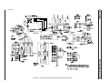
TROUBLESHOOTING
Figure 4-2. ESP-400 Power Source Wiring Diagram (Sheet 2 of 2)
SECTION 5
5.1
REPLACEMENT PARTS
General
Replacement Parts are illustrated on the following figures. When ordering replacement parts, order by part number
and part name, as illustrated on the figure. DO NOT ORDER BY PART NUMBER ALONE.
Always provide the series or serial number of the unit on which the parts will be used. The serial number is stamped
on the unit nameplate.
Replacement parts may be ordered from your ESAB distributor or from:
ESAB Welding and Cutting Products
Attn: Customer Service Dept.
P.O. Box 100545
411 S. Ebenezer Road
Florence, SC 29501-0545
Be sure to indicate any special shipping instructions when ordering replacement parts.
For technical assistance directly from an ESAB service representative, call (803) 664-4416. Additionally, ESAB offers
toll free facsimile (FAX) service via 1-800-446-5693.
20
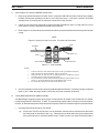
SECTION 5
1
REPLACEMENT PARTS
2
3
5
4
6, 7, 8
9
10
11
12
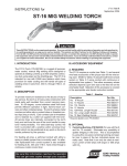
PANEL
REMOTE
13
CURRENT CONTROL
16
15
14
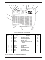
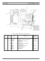
Figure 5-1. ESP-400 Power Source (Front View)
Item
No.
Qty
Req.
Part
No.
1
2
3
4
5
6
1
1
1
1
1
1
2062290
672539
598227
950122
672542
9950715
7
8
9
10
11
12
13
14
15
16
1
1
1
1
1
1
1
2
1
1
673999
2062170
634518
1006733
33077
99513496
33076
2091544
33075
33073
Description
DC Voltmeter, 0-500 Volts
DC Ammeter, 0-500 Amperes
Miniature Pilot Light - Thermal Overload
10 Ampere Circuit Breaker
Pilot Light - Power
*Current Control Potentiometer, 15K
Ohms, 2 W
Shaft, Lock
Knob
Panel - Remote Switch, DPDT
19-Pin Receptacle
Top Cover
Decal, Warning (not shown)
Right Side Panel
Decal, Warning (not shown)
Left Side Panel
Silk-screened Front Panel
*Any linear potentiometer, 5K to 25K ohms, will work satisfactorily.
21
Ckt.
Symbol
VM
AM
TH
CB
PL
R28
SW1
J1
SECTION 5
REPLACEMENT PARTS
1
2
10
9
3
4
C21
C22
5
8
6
7
REF: BLACK JUMPER WIRE
DISCONNECTED FROM C22(+)
FOR PARALLEL OPERATION.
CONNECT BOTH ENDS OF
JUMPER WIRE TO C21(-) TO
PREVENT LOOSE END FROM
TOUCHING OTHER PARTS.
RECONNECT ONE END OF
WIRE TO C22(+) FOR SINGLE
POWER SOURCE OPERATION.
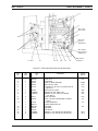
Figure 5-2. ESP-400 Power Source (Right Side View)
Item
No.
Qty
Req.
1
2
3
4
1
2
1
2
33334
17300008
950173
17295125
5
6
1
1
33074
672772
7
8
2
1
1
1
1
950627
33424
2062211
951275
950116
9
10
Part
No.
Description
Main Transformer Assembly
Resistor, 8 ohm, 300 W, 10% (fan shroud)
Main Contactor
Resistor, 250 ohm, 225 W, 5% (on
chassis base)
Rear Panel
Capacitor, 10 µF, 370 V ac (same as
Item 2, figure 5-4)
Capacitor, 4200 µF, 350 W V dc
Inductor Assembly
Thermostat (P/O Item 8)
Filter, Line, 10 A
Filter, Line, 2A
22
Circuit
Symbol
T1
R9,10
K1
R13,14
C18
C21,22
L1
FN1
FN2
SECTION 5
REPLACEMENT PARTS
1, 2
3
REF: PILOT
ARC WORK
4
16
REF: NEG
OUTPUT
TERMINALS
15
REF: WORK/
POS. OUTPUT
TERMINALS
14, 13, 12
11
10 9
8, 7
6
5
SEE ITEM 14
FIGURE 5-1
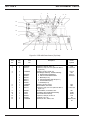
Figure 5-3. ESP-400 Power Source (Left Side View)
Item
No.
Qty
Req.
1
2
3
4
5
1
1
1
1
1
2062357
951756
674970
951223
672772
6
7
8
1
1
1
951222
17300020
17280010
9
10
2
1
672577
950228
11
1
1
1
1
1
2
2
677384
2062211
2062334
673676
672330
17300001
17300008
12
13
14
15
16
Part
No.
Description
Fuse, 30 A
Fuse Mount
Filter, PC Board Assembly
Shunt, 50 mV, 500 A
Capacitor, 10 µF, 370 V ac (same as Item 8,
figure 5-4)
Shunt, 100 mV, 500 A
Resistor, 20 ohm, 300 W, 10%
Resistor, 10 ohm, 100 W, 5% (behind
R15, Item 5)
Fuse Link, 500 A
Fuse, 4 A, 500 V (behind plate on chassis
base)
Control Transformer
Thermostat (P/O Item 11)
Fan Motor
Fan Blade
Fan Shroud
Resistor, 1 ohm, 300 W, 10% (fan shroud)
Resistor, 8 ohm, 300 W, 10% (fan shroud)
23
Circuit
Symbol
F6
PCB3
SH1
C19
SH2
R15
R4
F3,4
F5
T2
M1
R5,6
R7,8
REPLACEMENT PARTS
SECTION 5
2
1
3
4
5
14
14
14
7
12
13
11
10
7
9
7
6
Figure 5-4. ESP-400 Power Source (Top View)
Item
No.
Qty
Req.
Part
No.
1
2
1
3
2232378
672772
3
4
17280010
5
6
7
3
4
3
3
3
1
2
1
1
3
9
10
11
12
13
14
1
1
1
1
1
5
635568
31492
31444
993539
673458
17300008
2062304
950634
950124
950177
950711
672225
17280210
635686
672772
Description
Capacitor, 1300 µF, 450 V dc
Capacitor, 10 µF, 370 V ac (same as Item 6,
figure 5-2)
Resistor, 10 ohm, 100 W, 5%
Main Bridge Assembly. Includes following:
a. Reverse Silicone Rectifiers
b. Silicone Controlled Rectifiers
c. Bar Stud (for 4c.)
d. Spring Assembly, 2000 lbs (for 4c.)
e. Thermal Switch (for 4)
f. Standoffs (for 4)
Resistor, 1K ohm, 100 W
Terminal Block, 8-Position
Capacitor, 10 µF, 370 V ac (same as Item 3,
figure 5-3)
Terminal Block, 18-Position, 20 A
Constant Current PC Board Assembly
SCR PC Board Assembly
Capacitor, 1500 µF, 50 W V dc
Contactor, 110 V ac
Resistor, 8 ohm, 300 W, 10%
24
Circuit
Symbol
C26
C13,14,15
R1,2,3
BR
D4,5,6,7
SCR4,5,6
R27
TB4
C16,17,25
TB1
PCB1
PCB2
C20
K2
R22,23,24,25,
26
REPLACEMENT PARTS
SECTION 5
1, 2
6
11 (4 places)
10
6
1, 2
3, 4 (3 places)
7
5 (6 places)
8
9
Figure 5-5. ESP-400 Power Source Boost Bridge Rectifier
Item
No.
Qty
Req.
1
2
3
4
5
6
7
8
9
10
11
2
2
3
3
6
2
1
3
1
3
4
Part
No.
2062357
951756
950066
676743
672348
92W11
676770
950527
676765
950169
950065
Description
Fuse, 30 A
Fuse Mount
Silicon Controlled Rectifiers
Heat Sinks (for SCR1-3)
Capacitors
Terminal Board
Positive (+) Heat Sink
Silicon Rectifier Diodes
Negative (-) Heat Sink
Capacitors
Metal Oxide Varistor
25
Circuit
Symbol
F1,2
SCR1-3
C1-6
TB2-3
D1-3
C7-9
MOV1-4
ESAB Welding & Cutting Products, Florence, SC Welding Equipment
COMMUNICATIONS GUIDE - CUSTOMER SERVICES
A. CUSTOMER SERVICE QUESTIONS: Telephone (803) 664-5540/Fax: (800) 634-7548
Order Entry
Product Availability
Pricing
Hours: 8:30 AM to 5:00 PM EST
Order Changes
Saleable Goods Returns
Delivery
Shipping Information
B. ENGINEERING SERVICE: Telephone: (803) 664-4416 / Fax : (800) 446-5693
Welding Equipment Troubleshooting
Hours: 7:30 AM to 5:00 PM EST
Warranty Returns
Authorized Repair Stations
C. TECHNICAL SERVICE: Telephone: (800) ESAB-123/ Fax: (803) 664-4452
Part Numbers
Technical Applications
Hours: 8:00 AM to 5:00 PM EST
Performance Features Technical Specifications
Equipment Recommendations
D. LITERATURE REQUESTS: Telephone: (803) 664-5501 / Fax: (803) 664-5548
Hours: 7:30 AM to 4:00 PM EST
E. WELDING EQUIPMENT REPAIRS: Telephone: (803) 664-4469 / Fax: (803) 664-5557
Repair Estimates
Repair Status
Hours: 7:30 AM to 3:30 PM EST
F. WELDING EQUIPMENT TRAINING:
Telephone: (803)664-4428 / Fax: (803) 664-4476
Training School Information and Registrations
Hours: 7:30 AM to 4:00 PM EST
G. WELDING PROCESS ASSISTANCE:
Telephone: (803) 664-4248 / Fax: (803) 664-4454
Hours: 7:30 AM to 4:00 PM EST
H. TECHNICAL ASST. CONSUMABLES:
Telephone: (800) 934-9353
Hours: 7:30 AM to 5:00 PM EST
IF YOU DO NOT KNOW WHOM TO CALL
Telephone: (800) ESAB-123/ Fax: (803) 664-4452/Web: http://www.esab.com
Hours: 7:30 AM to 5:00 PM EST
F-15-108
5/97
3C
Printed in U.S.A.