1
available from Technological Arts. You can build up a collection of different application circuits, and
use them all with the same microcontroller board. This is especially advantageous in an educational
environment, where the student can progress from simple to more complex applications throughout
a semester, or from one course to the next-- perhaps even using the board in a final project. In fact,
where budgets are tight, different students can share the same microcontroller module, and plug in
their own interface cards when it’s their turn to use it.
Using Adapt9S12DP256 with Solderless Breadboards
When used with an optional adapter (#ADHDR50-F), the module will easily plug vertically
into any standard solderless breadboard. The resulting footprint is equivalent to a 50-pin narrow
DIP, and has a similar pin-numbering sequence (ie. wraps around the end, from pin 25 to 26). Plug
the adapter into your breadboard, wire up your circuits, as required, and then plug the module into
the adapter. Now you can use DBug12 to load your code into the MCU to evaluate and develop your
application ideas.
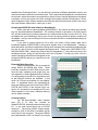
If you want to access signals on H2 as well, you’ll need a 50-pin ribbon cable and a
breadboard adapter (#ADIDC50-M) to bring those signals down to the breadboard. Perhaps a
better alternative is a planar configuration utilizing cards mounted with solderless breadboards that
plug into H1 and H2 in place of the supplied prototyping cards. These cards (#AD12SBH1-FRA1
and #AD12SBH2-FRA1, respectively) feature dual-row receptacles (“F”-style connector) next to the
breadboard section, giving you easy access to all of the I/O signals. To build your circuit, it’s just a
matter of plugging wires between the signals on the
receptacles and the places you need them on the
breadboard.
Expanded Mode Operation
A second jumper block (JB1) is provided for
setting MODA and MODB logic levels. These
levels are sensed by the MCU after reset to determine the chip’s operating mode (single-chip, narrow expanded, or wide expanded memory modes).
You will normally run the MCU in single-chip mode,
so that DBug12 functions are available. In this
mode, all I/O ports are available for user applications. In expanded modes, the multiplexed address and data bus lines are formed from PORTA,
PORTB, and PORTK on the second 50-pin connector, H2, and are thus not available as I/O ports.
When operated in this mode, additional memory
can be added externally.
Communications
Two RS-232-compatible serial interface
ports (RX & TX only) are included on
Adapt9S12DP256, allowing communication with a
PC, or any other device which has an RS-232
serial port. The primary RS232 channel (implemented on SCI0 of the MCU) is available via the
usual 9-pin D-sub connector. The second RS232
port (implemented via SCI1 of the MCU) is brought
3