1
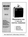
Kenmore
2700
17 GALLON
CENTRAL HUMIDIFIER
Installation
Maintenance
Repair
Parts
Troubleshooting
Sears, Roebuck and Co., Hoffman Estates, IL 60179 U.S.A.
contents
WARRANTY ...........................................
BEFORE YOU START
Rules for Safe Installation
2
and Operation ...................................
2
Tools and Materials Needed .............. 2
UNDERSTANDING HUMIDITY .............. 3
SELECTING A LOCATION .................... 4
INSTALLATION...................................... 4
DISASSEMBLY...................................... 4
WATER SUPPLY ................................... 6
HUMIDISTAT.......................................... 7
OPERATION .......................................... 8
MAINTENANCE ..................................... 9
SERVICE HINTS .................................. 10
REPAIR PARTS .................................... 11
introduction
Please read the instructionsbeforeyou installand useyour humidifier.This will helpyou obtainthe fullvalue from the humidifier.It will
also helpyou avoidany needless service cost, ifthe problemissomethingwe cannotcontroland cannotcover in our Warranty.
FULL ONE YEAR WARRANTY
ON HUMIDIFIER
If, within one year from the date of pumhaee, this humidifier fails due to a defect in material or workmanship, Seers will
repair it, free of charge.
WARRANTY SERVICE IS AVAILABLE BY SIMPLY CONTACTING THE NEAREST SEARS STORE OR SERVICE
CENTER IN THE UNITED STATES.
This warranty gives you specific legal rights, and you may also have other rights which vary from state to state.
This warranty DOES NOT cover the replacement media pad.
Sears, Roebuck and Co., Dept. 817WA, Hoffman Estates, IL 60179
DO-IT-YOURSELF CHECK LIST
Ifyoufeel thefollowingoperationsare withinyourskills,youshould
have no difficultyinstallingthis humidifier.
[]
[]
Cuttingand drillingsheet metal.
Using hand tools:screwdriver,wrench,etc.
[]
Rookingup lowvoltage electricalconnections.
You must realize that the wrong use of any tool can be dangerous. Be sure you know how to use the tools and equipmentto
avoid any possiblehazards. If you have any doubt we ask that
you contactyourSears salesperson.They willarrangefor professional installation.
SEARS INSTALLATION WARRANTY
SEARS INSTALLATION POLICY
Allinstallationlaborarrangedby Sears willbe performedin a neat,
workmanlikemannerin accordancewithgenerallyacceptedtrade
practices.Further, all installationswill complywith all local laws,
codes, regulations, and ordinances.The customerwill also be
protected, during installation, by insurance relatingto property
damage, Work]nan'sCompensation,and publicliability.
In additionto any warranty extendedto you on the Sears marchandise involved,which warranty becomes effectivethe date
the merchandise isinstalled,shouldtheworlonanshipofanySears
arrangedinstallationprovefaultywithinone year, Searswill, upon
noticefrom you, cause such faults to be corrected at no additionalcostto you.
before you start
RULES FOR SAFE INSTALLATION
& OPERATION
1.
Read these rules and the instructionscarefully.Failuretofollow the rules and instructionscouldcause bodilyinjuryand/
or propertydamage.
2.
Check your local buildingcodes and utilitystandards.The
installationmustcomplywith their rules.
Alwaysshut offthefurnace blowerbeforeinstallingor servicingthe humidifier.
3.
4.
5.
6.
7.
8.
Always wear safety glasseswhen installingor servicing.
HUMIDIFIER MUST NOT BE INSTALLEDIN AREA WHERE
FREEZING IS POSSIBLE OR LEAKING WOULD CAUSE
WATER DAMAGE.
Followa regularservice and maintenanceschedule.
Always shut off electricityand water to the humidifierbefore
servicing.
When thefurnace blower is usedfor air-conditioning, the humidifierdampershouldbe closed, andthe humidistatshould
be turned to the minimumhumiditysetting.
g. NEVER OIL ANY PARTOFTHE HUMIDIFIER.
10. To preventover humidification,humidifiermust not be operated above humidiatat high position or above the +20
position (whichever applies) except briefly to test operation after installation or servicing.
TOOLS AND MATERIALS NEEDED
• Safety Glasses
• Straightedge ruler
•
Screwdriver(flat point,and
• Pencilor grease pencil
•
Phillips,mediumsize)
File
•
•
Level
Hand drillor grounded
electricdrill
•
Hammer
• Drillbits, 5/32", 118"
•
Smell adjustablewrench
• "r]nsnipsor metal
cuttingsaw
• Center punch
• Springhose clamp pliers
• Wire strippersor razor knife
THANK YOU!
Thank you for selectinga Sears Humidifier.It willprovideyears of service if you give it a littlecare.
UNDERSTANDING
HUMIDITY
Humiditycan be puzzling. It cannot be seen, heard, touched,
smelledor tasted. Many people do not understandwhata humidifier will or will not do.
them at all, especiallyin the corners,you have too little. (NOTE:
Moisturewill not normallyformon thermopaneor whenstorm win.
dows are used.) ff there is some moisturein the windowcorners
and alongthe edges,the humidityisjustabout right.This isa good
role of thumb, it you do not have an expensivepiece of testing
equipment.Yourcomfortis another good check.
Probablythe best way to judge whether the humidityis too high,
too low or aboutright isto watchyour windows.If they are heavily
fogged you most likelyhave too much. If there is no moistureon
TYPICAL QUESTIONS
ASKED
1. Why do moisture requirements vary from home to home?
5. Whet else causes static shock besides low humidity?
Requirementsdepend on the amount and drynessof airto be
humidified.The largerand more looselyconstructedthe home,
the greaterthe quantityof moisture required.
Some typesof carpets tend to create more staticthan others.
While the properhumiditylevel will reduce the static level, it
may noteliminatestaticentirely.
2. How can I best check my home's relative humidity?
6. What Is the safe humidity level for my home?
First give your humidifiertime to build up the humidityto an
acceptablelevel. Instrumentsare availableto measure relative
humidity,but from a practical standpoint,your comfortis the
best guide.You cannot depend on table top or wall hung dial
gauges.
In order to determinethe safe relativehumidityfor homes exposedtovariouslow outsidetemperatures,NESCA* conducted
tests and publishedrecommendedhumiditylevelsfor various
outdoortemperatures.These are shown in the chart. These
levels help preventdamage to your home such as water running downthe walls or even buildingup insidethe walls.
The safe indoorrelativehumiditypementageis nota fixednumber but will increaseor decrease as the outdoortemperatures
rise or fall.
3. How long will It take my humidifier to build up the
humidity In my home?
Much dependson the outsidetemperature,timeof year, home
construction,and howdriedout the home hasbecome.In soma
cases, it may take a week or mare.
Outside Temperatures
4. What are some of the common things that cause higher
then average sir leakage In the home, therefore causing
low humidity?
A. Jalousiewindows
B. Open fireplacedampers
C. Cracks aroundwindows end doors
D. Open doors end windows
E. Unusuallylarge attic or foundationvents
F. Range hoodsand bath fans
Maximum Safe Recommended
Indoor Relative Humidity
-10 °
F
20%
0°
F
25%
10°
F
30%
20 °
F
35%
30 °
F
35%
*NESCA - Ndonal EnvironmentalSystemsContractorsAuociation.
3
selecting a location
Consider these points as you choose the location for your
humidifier.
Locate humidifieron supply air plenum(Fig. 1) or return air plenum. Ifthe humidifierisinstalledon the rstumair plenum,the flexible hose, roundopening, is connected to the supplyair plenum.
16 inch minimum
40 inch maximum using flex
hose provided*
• Purchaseadditional
hosefo_greater spans.
If furnace is equipped with air conditioning, humidifier should be
mounted above or at slope side of "A" coil to avoid possible splashing (Fig. 2) of water.
ReturnAir
Plenum
Fumac_
Humidifiershouldbe installedsothat ifthe humidifieror any other
connectionsshouldleak, the resulting flowofwater willnotcause
damage. Under no condition isSears and the manufacturerto be
held liable for any water damage in connection with this humidifier.Never installhumidifierin attic or crawlspacewhere freezing
may occuror leaking will cause water damage.
If holes between supply air plenum and return air plenum must
be located more than 40 inchesapart (Fig. 1), standard 6 inch
round pipe and fittings(not supplied)may be used, or an 8 foot
sectionofflexibletube No. 28115205 may be pumhasedthrough
the Searsparts departmenLMaterialsneededforthis typeinstallationare available at Seam.
installation
The humidifieris shippedwith the block-offpanel on the
rightside (Fig. 3). This issuitableforinstallationas shown
in Fig. 1, above. If this is suitable for your installation,
remove parts as shown under DISASSEMBLY.
Place Humidifier
Duct
Supply Ai
Plenum
Air ConditionerCoil
AS CONVI=HTI=U
Right Hand Flange
AS SHIPPED
Left Hand Flange
Block-Off
Panel
If you require the block-off panel on the left side (Fig. 4),
start with DISASSEMBLY then remove block-offpanet from
dghtflange and install with the same screws on left flange.
Block-Off
Panel
FIBER PLENUM DUCTS
NOTE: The mountingscrewssuppliedere for standard installationon sh_t metal plenumducts.
If you have fiber plenum ducts, install the humidifierand components withthru-belts, nuts,and
washers (not supplied).(This fiber duct installation hardware is not supplied and must be purchased from you local hardware store.)
Bypass Flange
Bypass Flange
vent
eye injurywhen
installinghumidifier.
CAUTION:
Safety glasses
shouldbe wornto pre-
disassembly
1.Take off front panel by slidingpanel up and pullingout at
the bottom.
2. Remove corrugated spacer and by.peesbootwhich contalnsdamper,collar & flextube and tube damp.
3. Remove media pad by liftingbottom edge up slightlyand
pullingout.
Cese/umemUy
[] 1
6
Mark a level line on the supplyair plenum (Fig. 6).
[]
Drillthe four holesmarked on the plenum with a 1/8"
drillbit. Holes mustbe locatedat end of slot (Fig. 7).
[] 7
Attach the humidifiercase assembly on the plenum
using4 #8 screwsprovided.
Level Line
1
Drill4
1/8" Holes
4" Min.
Sup,ply
Air
J_
Furnace
Cut Along-This Line
i Plenum
[] 2
_tcou[
This Area
•
Hold case assembly againstthe plenum with bottom
edge ofrear openingon level line. Mark fourcomers of rectangularopeningand four screwlocationson plenum,Screwholesmust
be locatedat end of slot (Fig, 7).
Level
_ne
•
Furnace
j Plenum
[] 8
Hold collarand flexible tube assemblyagainstcold air
plenum at desired location.
[] 9
Locstions
Mark roundopening inside collar and five mounting
holes(Fig. 9).
[] 10
Level
Line
Centerpunchfive screw locations.Drillor puncha large
holewithinthe roundopening.Cut out the area insidethe round
opening.Drillthe five holes (Fig. 9).
_l, SupplyAir
Plenum
I
Furnace
1
[] 3
Connect corner marksto outlinerectangularopening.
Center punchfour screw locations(Fig. 8).
Hot Air
Plenum
[] 4
Drill or punch a large hole in one corner of rectangle.
This willallowyou to insertthe tin snipsor metalsaw.
Cold Air
Plenum
Furnace
I
CAUTION: Be sure not to drill or cut intoair conditioning
coil or tubing.
I
[] 5
Cut out thearea insidethe rectangle.Ifany ofthe edges
are rough,file them smooth(Fig. 8).
5
installation
[] 11
Attachcollarand flexiblehoseto cold air plenumusing(5) #8 screwsprovided.Ifaddifionaiflexiblehoseis requiredan
eightfoot length is availablethroughthe partsdepartment,order
28115205. Beforeflghtening screwsinsertdamperbetweencollar
and plenum (Fig. 10). It shouldbe open for humidifieroperation.
WATER SUPPLY
I
[] 1
Waterforthe humidifiermustbetakenfroma nearby
coldwater line.Turn offthewater supply.Drain byopeninga faucet at a lowerlevel ofthe line.
(Slideshut
beforeusingair
conditioning.
Slide openat
startof heating
[]
season.)
___
Mountthe saddlevalve on thewater lineas closeto
SPECIAL NOTE: When measuring the distancefrom the
saddlevalvelocationtothe humidifier,keep in mindthatthe
tubing mustbesupported;therefore, it mustrunalongceiling
and walls. Measurealongthe path the tubingwillfollow.
[] 12
Attach boot to humidifierusing (2) #8 screws engaged in the tinnermannuts providedin bypass flange. Connect
the flexible tube as shown usingclamp provided.Do not allow
flexibletube to come within3" of furnace flue pipebecauseof flue
pipe'sextreme heat (Fig. 11).
[] 3
_
out the piercingpin by tumingthe "T" handle
counterdockwiseand then clampthe saddlevalve bodysecurely
onthe waterlinewith rubber gasketposifionedas shown(Fig. 13).
On galvanizedor copper pipe over 5/8", firstdrilla 5/32" hole.
#8 Screw
/
2
the humidifieras possible.You have bean suppliedwith(10) feet
of 114"plastictubing.
amper Blade
(5) #8 Screws
tubing because it may become disconnected when used with
CAUTION:
Use plastic tubing supplied, Do not use copper
hardware supplied.
I
drill.
AUTION: For safety use a handdrillor groundedelectric
[] 4
Turn handleclockwiseuntilit haspiercedthe water
lineand valve iscompletely closed(Fig. 13).
#8
[] 13
: Clamp
[] 5
Partiallyuncoilthe tubing. Slidethe brasscompression nut over the tubing. The threads in the nut must face the
tubing end. Place the brass compressionsleeve as shown(Fig.
13). Slipbrass insertintoend of tubing.
The waste water drain mustbe installed.The drain
is inthe bottomof the humidifierreservoir(Fig. 12). Use 1/2" I. D.
x 10"plasflc tubing to connect drain. (Tubing is supplied.)Additional tubing is available at yourSears store,Stock No. 42-3433
II
[] 6
Insert the tubing end into the saddle valve at
threaded stem "A" (Fig. 13) as far as it will go. Thread the brass
compression nutontothe valve, then tightengentlywith a wrench.
Take care notto overtightenthe nut.
Ill
I
Brass CompressionSleeve
='q_-- Spring
f
°%%
L.> Hose To
Drain
I
CAUTION: Wear safety glasses.
I
Brass
CompressionNut
[] 14
Uaingspringhoeaclamppliem,expandhoeaclamp
and slide over en_lof _
tubingapproximately2 inches.Slide
plastictubing onto waste water dr_n. Expandhose clamp and
poaiUonto clamp tubingto waste water drain (Fig. 12).
MOUNTING SADDLE VALVE
6
Brass Insert
[] 7
Unwind the rest of the tubing. Take care not to Idnk
it. Run the tubing along flat surfaces to the humidifier. Support the
tubing as needed to avoid contact with furnace.
NOTE: The humidistat as supplied is assembled for return
air plenum installation (Fig. 16.).
RETURN AIR PLENUM MOUNT
[] 1
[] 8
Close previouslyopened faucet.Turn on main water supply.Place a pail under the end of the tubing.Open the
saddlevalve. Flush the line. Make sure there are no leaks along
the lineor at the valve. Turn valve off.
LOCATE THE HUMIDISTAT on return air plenum
(Fig, 15). DO NOT install humidistat on supply air plenum.
HUMIDISTAT MUST BE MOUNTED AT LEAST 6" UPSTREAM
FROM FLEXIBLE HOSE (OR HUMIDIFIER IF HUMIDIFIER
INSTALLED ON RETURN AIR PLENUM).
[] 9
With water supply tubing cut to the properlength,
slidethe plasticcompressionnut overthe tubing.Slipbrassinsert
intothe end of tubing.
--
._.. I
_%
/..i
--
Humidistat
AirPlenum
On Return
Check For Leaks,
Tighten if Necessary._
/I
_
only/ IF
6"
Minimum
PlasticTubing
Supply
I-J'F--_-II
J,_,.l[... _,. _
I
t
I
I
A
_ Air Flow J
_Fu
r"'nac_"
Brass Insert
[]
Compi'ession
Nut
2
.1_. I
/
Plenum
I
I
HUMIDISTATMOUNTS IN A HORIZONTAL POSI-
TION. Peel paper backingfrom template and paste it on return
air plenum where humidistatis to be mounted.Keep level.
Valve
[] 3
Drill 118" holes for the four mounting screws as
shownon the template.
[] 10
Insertthe tubing end intothe solenoidvalve fitting
asfar as if willgo and hold itthere, threadthe plasticcompression
nutontothe fitting, then tightensecurely,finger tight(no wrench).
Do not over tighten nut (Fig. 14).
[] 4
cut outcenter portionoftemplatewithinsolidlines.
[] 5
After removing paper backing from gasket, apply
gasket around return air plenum opening as indicated on ternplate (Fig. 16).
[] 11
Turnon watersupplyat saddlevalve.Checkfor leaks
at solenoid valve fitting and plastic compression nut.
I
NOTE: water will not flow thru humidifieruntilelectricalinstallationis completed.
I
ApplyGasket Here AroundOpening
I
Backplate
Mounting
Screws
(4)
installation
Plenum
Opening
HUMIDISTAT
The humidiatatis designedto mounton the returnair plenumof
your furnace or on an interior wall of the home. The return air
plenum,however, is the preferred locationfor sensing the everage humiditythroughoutyour home and is the locationcovered
byinstallationsteps 1 through11. (ifyou decideonthe wall mount
location,the humidistatcontrolunitmustbe removedand mounted
to the oppositeside of the plasticbackplateeo it willbe housed
l_aideof the plasticcover- omitsllaft extana]on- purchaseadditional low voltage wire and run wire inside of wall to exit hole
withinthe loweropening of the backplate.)
_" ControlUnit
I Mounting
Screws (2)
LSheft Extension
7
WIRING
TOCONSTANT
120VACUNE
EXTERNAL
TOFURNACE
Junction _
_U
[] 6
Usinglowvoltagewire supplied,connectspadeter-
J
Ill I
IIII
IIII
Inllal
SiI# _ddl
In Rltum
Air Plenum
(_ _-._lly _ o=_s)
Pu_
thisacce_loty
separately
ifneeded.
Av=_ _o_ s_-s P,_,_ Ser_=
I
minalsto solenoidvalve on top of humidifier.
J
NOTE: Wiring mustconformto localcodes.
[] 7
[] 12
[] 8
Feed wires thru opening in humidistatback plate
and attachto screwterminals.Mounthumidistaton retumair plenum using (4) #8 screwsprovided.Install shaftextension,cover
and knob (Fig. 16).
operation
Position and support wire to humidistat location.
Separate wire. Cut only one wire, strip ends.
I
Attach"OperatingInstructionLaber to returnair plenum nexttothe humidistat.Peel offpaper backingand sticklabel
in desired location.
[] 1
Set knobto the lowest temperaturepredictedfor a
24 hourpe_nd. Because ofdifferencesin houseconstruction you
may wanttotrya higheror lowersettingtoachieveproperhumidity.
CONTROL CIRCUIT: Forproper operationand water conservefion, this humidifiermustbe wiredso it willoperateonlywhen the
furnace blower is runningand the humidistatcalls for additional
humidity.Two methodsare shown(Fig. 17 and Fig. 18):
[] 2
Change knob settings as outdoor temperature
changesoccur.
Fig 17: WIRING INTO FURNACE - FOR ANY FORCED AIR
FURNACE WITH SINGLE SPEED 120 VAC BLOWER ONLY.
[
WARNING: DO NOT LEAVE KNOB SET IN "TEST" POSITION ABOVE %20" OR HUMIDIFIER WILL RUN CONSTANTLY.
CAUTION: Do not use this methodwith multi-speedblowem or blowem otherthan 120 VAC.
I
Rg 18: WIRING EXTERNAL TO FURNACE- FOR ANY FORCED
AIR FURNACE INCLUDING FURNACE WITH OTHER THAN 120
VAC BLOWER MOTOR OR FURNACE WITH MULTI-SPEED
BLOWER MOTOR.
IF SWEATING OF WINDOWS OR WALLS OCCURS OR IF AIR
IS TOO DRY:
Check dial seffing. Indicatorshould point to the lowest24 hour
temperature. If settingdoes not agree, readjust knobto proper
NOTE: Some furnacesare equippedwith accessoryterminalsthat can be usedfor the humidifier.In this case, consult
the fumane manufacturer'srecommendationfor wiring.
correctand conditions have not changed, rotate knob beck and
forthfromTEST to MINIMUM HUMIDITY SETTING. If humidifier
numberand
wait
24control
hoursfor
sweatingto stop. Ifdial settingwas
goes ON and
OFF,
is operatingproperly.
i
AIR CONDmONING - IMPORTANT:
If your furnace has air conditioning (cooling),dose the damper
completely duringsummer months and tum the humidistatto the
MinimumHumiditysetting.BE SURE TO OPEN DAMPER DURING HEATING SEASON AND RESETTHE HUMIDISTAT.
[] 9
Tum offelectricityat fusebox. Using(two)wire nuts
and conduit nut supplied, install24 VAC transformerto 120 VAC
supplyjunction box followingthe control circuitselected so the
transformer will be powered onlywhen the fumaceblower is running. Do not use existingtransformer on fumace.
WATER FLOW RATE:
At standardwater line preseureof 50-60 PSI (poundsper square
inch), water willflow through humidifierat approximatelyfour (4)
gallonsper hour.About 0.7 gallonspar hour of the four will be
evaporated,leaving3.3 gallons to be drainedaway.Since the furnsoe only runsan estimated30-40% of the beating season, and
the_umldifter is wired to operate only with the fumase blower,
and only when humidityIs required,the actual amount of water
drainedper day is much less than wouldbe expected.
[] 10
Connect spade terminals of low voltage wire to
spade terminals of transformer.
[] 11
Tumonalectridtyandtastoparationbyobasrvinglf
water is flowingto drain while fumace is running and humidistat
dial Is set to "toet"position.
8
SPLASH INSIDE HUMIDIFIER:
coating of lime will build up. It could, in extreme cases, cause
leaking of water from the humidifier.
This humidifier depends on the difference of air pressu re between
the supply air plenum and the return air plenum to propel air
through the humidifier. Some furnaces have higher pressures than
others, This could result in air traveling at high speed through the
humidifier. This can cause droplets of water to be picked up and
splashed against the inside of the humidifier case. Eventually a
TO REDUCE SPLASH:
Partially close the damper located in the collar on the return air
plenum. Some experimenting may be necessary to find the proper
setting.
maintenance
CLEANING
periodic preventative
maintenance
AND SERVICE INSTRUCTIONS:
CAUTION: Before performing service, inspection, or
maintenance:
[] 1
Periodic inspection and preventative maintenance of these components is important for continued, efficient operation of the humidifier. Refer to exploded view for location of components.
Turn off electricity at furnace, humidifier, and humidistat.
2
Turn off water at humidifier saddle valve.
3
Wear safety glasses.
CAUTION: Be sure water and electricity are turned off
as advised above.
distribution
This humidifier is an appliance that evaporates water in large quantities. The dissolved minerals normally found in tap water in varying degrees are left as lime deposits on the media pad and other
parts in contact with the water. Deposit build-up will reduce humidifier output. Annual cleaning and replacement of the media
pad is recommended. Since water conditions vary, it may be necessary to service more or less often. Establish your own service
schedule. Ease of service has been foremost in the design of this
humidifier following the steps below:
servicing
1
[] 1
Lift Off front panel.
[] 3
Reassemble pad set and distribution trough and secure with the (2) #6 screws.
the media pad
drain tube
Lift Offfront panel.
I_ 1
Using spring hose clamp pliers, expand hose clamp
and remove drain tube.
[] 2
Clear internal lime and calcium deposits by flexing
or striking on hard surface.
3
If necessary, clean inside of humidifier case (especially
lower drain area) with water and vinegar solution, detergent and
water, or Sears All-Purpose Humidifier Cleaner, Stock No. 42-14713.
[] 3
4
4
Install media pad by sliding top edge up and pivoting bottom edge into position.
solenoid
[] 1
Replace front panel.
6
Turn on water and electricity and test operation by
observing if water is flowing to drain while furnace is running and
humidistat is set to =test" position.
[] 7
trough
Loosen the (2) #6 outer screws on top of the humidifier. Remove and clean the distribution trough and pad set.
Replace pad set (Pt. No. 35587901) if badly soiled.
2
5
I
[] 2
Remove media pad by lifting bottom edge up slightly
and pivoting out. Inspect and replace if badly b_ocked with mineral
deposits. (Media Pad available from Seam, Stock No. 42-14711 .)
[]
I
I
Flush with water under pressure.
Reinstall drain tube and hose clamp.
water filter
Remove water line at solenoid.
[] 2
Remove nylon elbow inlet fitting filter/orifice assembly from solenoid valve by unscrewing (turn counter-clockwise).
_i3
Check for clogging by blowing through one end. If
clogged, replace with new fitting assembly, Part No. 05291201.
Set humidistat according to outdoor temperature as
instructed on operating instruction label. Unit is back in operation.
9
I
[] 8
Set humidistataccordingto outdoortemperatureas
instructedon operation instructionlabel. Do not leave in 'test"
position.Your humidifiershould now be ready for many more
monthsol trouble-freeoperation.
flowcontrolorificewhichmustbe in placefor properoperation of your humidifier.(if not installed,too much waterwill
CAUTION:
This
special
fitting contains a brass filter and
flow
and may
cause
leaking.)
[] 4
summer shut down
Reinstall the nylon elbow inlet fittingfilter/orifice as-
sembly by carefully aligning the fine thread end containing the
flow control orifice into the solenoid valve and screwing in (clockwise) until moderately tight.
[]
5
[] 6
Turn humidistatdial counter-clockwiseto minimumsettingposition, close saddle valve, close bypass damper, and clean per
above.(As a reminder,you mightwant to put a tag or stickeron
the unitindicatingit has been shutdownfor the summer and will
requirestartup in the fall.)
Reinstall water line.
fall start up
Replacefront panel.
Open saddle valve and open bypass damper.Test operationby
observingif water isflowingto drain whilefumace is runningand
humidistatdial issetto 'test" position.Set humidistataccording to
outdoortemperatureas instructedon operationinstructionlabel.
Unit is back in operation.
[] 7
Turn on water and electricityand test operationby
observingifwater is flowingto drainwhilefurnaceis running and
humidistatis set to "test" position.Check for leaks and tighten
fittingas required.
service hints
Frequentlywhat seems to be a majorproblemcan be solvedvery easily.Listedbelow are the commonconcernswith any humidifier.
Check the simplethings first. Remove thefront panel and see if there is a crusty,whitelime build-upon the media pad.The lime buildup won't hurtthe humidifier,but will reduceitsoutput.Low outputmightjust mean yourhumidifierneeds cleaning.
CONDITION
Too little
Humidity
Too much
Humidity
Humidifier
Making Noise
WHAT TO CHECK
WHAT TO DO
1.
Check for obviousproblems.
1.
2.
Humidiatatsetting.
2.
3.
Water to unit.
3.
4.
Excessiveair lose in house.
4,
5.
Is damperopen?
5.
Slide damperout for winteroperation.
1.
2.
Humidiatatsetting.
Other humidificationsources.
1.
Turn knobcounter-clockwiseto decrease humidity.
2.
May be a temporaryconditioncaused by moisture
from laundering,bathing,cooking,etc.
1.
Tightenall fasteners.
2.
A slightsound is normalas water enters humidifier.
1.
2.
Mountingor plenum.
Water pressure.
10
a.
b.
c.
d.
Replacemedia pad.
Inspectmain fuse or circuitbreaker.
Check to see if solenoidisoperating.
Humidistatsettingtoo low,turn knobclockwise
to increasehumidity.
e. Check distributionpad set and clean or replaceif
dirtyor clogged.
Set for proper outdoortemperature- lowest24-hour
temperature.
Turn on saddlevalve and checkfor possible
obstructionin water line. Is water supplyconnected?Check solenoidwaterfilter and replace
inletfittingfilter/orifice assembly if clogged.
Closefireplace damper,seal arounddoorsand
windows.
repair parts
CENTRAL SYSTEM HUMIDIFIER
MODEL NO. 303.147012
KEY
NO.
1
2
3
4
5
6
7
8
PART
NO.
21597201
33521001
21595101
21594201
21594101
21594001
21601101
35561801
9
10
11
12
13
14
STD575025
STD575026
03001804
03028705
05291201
21597701
15
16
17
18
21598701
25514001
35587901
21582703
DESCRIPTION
KEY
NO.
PART
NO.
Case Assembly
Media Pad (42-14711 )
Front Panel
Speed Clip
Rubber Washer
Plastic Eyelet
Boot
Saddle Valve
19
20
21
22
23
24
25
26
(Includes Key Nos. 9 & 10)
Brass Compression Nut
Brass Compression Sleeve
Nut (No. 6-32 Thread) (2 Req.)
Screw (No. 6-32 x 1/2") (2 Req.)
Inlet fitting filter/orifice
Solenoid Valve
(Includes Key Nos. 13 & 15)
Outlet Fitting
Plastic Compression Nut
Distribution Pad (Set)
Plastic Supply Tubing (1/4" x 10 Ft.)
27
28
29
41067501
STD610603
03022701
21594501
21594701
43148901
43149102
21581001
STD610803
28098302
35548801
21603901
35587302
41053902
21595501
THIS IS A PARTS LIST, NOT A PACKING LIST
DESCRIPTION
Brass Insert (2 Req.)
Screw 6Z x 1/2" (6 Req.)
Nut 6Z (6 Req.)
Distribution Trough
Block-Off Panel
Damper
Collar & Flexible Tube (3 Ft.)
Tube Clamp
Screw (No. 8 x 3/8") (9 Req.)
Hose Clamp
Drain Tube (10 Ft.)
Lead Wire (10 Ft.)
Humidistat (24 VAC)
Transformer (24 VAC)
Owner's Manual (0796)
*Not Shown
11
Kenmore 303.14701 FURNACE HUMIDIFIER MAINTENANCE
(APPLY
THIS LABEL WHERE
EASILY
SEEN)
Cleaning frequency is dependent upon mineral content of water supply.
Check every 60 Days until schedule can bd determ_ned.
CAUTION: Before performing service, inspection, or maintenance:
off water at humidifier saddle valve, wear safety glasses.
Turn off electricity to furnace and humidifier, turn
SERVICING THE MEDIA PAD
1. Lift off front panel.
2. Remove media pad by lifting bottom edge up slightly and pivoting out. Inspect and replace if badly blocked with
mineral deposits, available from Seam (stock number 42-147tl).
3. If necessary, clean inside of humidifier case (especially lower drain area) with water and vinegar solution, detergent
and water, or Sears All-Purpose Humidifier Cleaner stock no. 42-14713.
4. Install media pad by sliding top edge up and pivoting bottom edge into position.
6. Replace front panel.
6. Turn on water and electricity and test operation by observing if watsr is flowing to drain while furnace is running
and humidistat is set to "test" position.
7. Set humidistat according to outdoor temperature as instructed on operating instruction label. Unit is back in
operation.
PERIODIC PREVENTATIVE MAINTENANCE
Periodic inspection and preventative maintenance of these components is important for continued, efficient operation
of the humidifier. Refer to exploded view in your owners manual for location of components. CAUTION: Be sure water
and electricity are turned off as advised above.
DISTRIBUTION TROUGH
1. Lift off front panel.
2. Loosen the (2) #6 outer screws on top of the humidifier. Remove and clean the distribution trough and pad set.
Replace pad set (part number 365879-01) if badly soiled.
3. Reassemble pad set and distribution trough and secure with the (2) #6 screws.
DRAIN TUBE
1. Using spring hose clamp pliers, expand hose clamp and remove drain tube.
2. Clear internal lime and calcium deposits by flexing or striking on hard surface.
3. Flush with water under pressure.
4. Reinstall drain tube and hose clamp.
SOLENOID WATER FILTER
1. Remove water line at solenoid.
2.
3.
4.
5.
6.
7.
8.
Remove nylon elbow inlet fitting filtedoriflce assembly from solenoid valve by unscrewing (turn counterclockwise).
Check for clogging by blowing through on end. If clogged, replace with new fitting assembly, Part No. 052912-01.
CAUTION: This special fitting contains a brass filter and flow control orifice which must be in place for proper
operation of your humidifier.
Reinstall the nylon elbow inlet fitting filtsdorifice assembly by carefully aligning the fine thread end containing the
flow control orifice in the solenoid valve and screwing in (clockwise) until moderately tight.
Reinstall water line.
Replace front panel.
Turn on water and electricity and test operation by observing if water is flowing to drain while furnace is running
and humidistat is set to "test" position. Check for leaks and tighten fitting as required.
Set humidistat according to outdoor temperature as instructed on operation instruction label. Do not leave in "test"
position. Your humidifier should now be ready for many more months of trouble-free operation.
Summer Shutdown
Turn humidistat dial to "minimum setting", close saddle valve, close bypass damper, and clean per above. (As a
reminder, you might want to put a tag or sticker on the unit indicating it has been shut down for the summer and will
require start up in the fall.)
Fall Startup
Open saddle valve and open bypass damper. Test operation by observing if water is flowing to drain while furnace is
running and humidistat dial is set to "test" position. Set humidistat according to outdoor temperature as instructed on
operation instruction label. Unit is back in operation.
PIN 21603801R10-0O
Kenmore
2700
17 GALLON
CENTRAL
HUMIDIFIER
For the repair or replacement parts you need
Call 7:00 a.m. - 7:00 p.m., 7 days a week
1-800-366-PART
(1-800-366-7278)
For in-home major brand repair service
Call 24-hours a day, 7 days a week
1-800-4-REPAIR
(1-800-473-7247)
For the location of a
Sears Repair Service Center in your area
Call 24-hours a day, 7 days a week
1-800-488-1222
For information on purchasing a Sears
Maintenance Agreement or to inquire
about an existing Agreement
Call 9:00 a,m, - 5:00 p,m,, Monday-Saturday
1-800-827-6655
SEARS
•taY.'fl,_,J 'l[_t_
America's Repair Speciahsts
Tell Sears You Want It Installed,
Then Relax...
When Sears arranges the installation, you can be sure the job is
done right. We will arrange for professional workmanship...and
we'll take care of the entire project. What's more, during installation you get insured protection...against property damage and
also against accidents to workmen. All you have to do is talk to
your Sears salesperson or call 1-800-865-6500 or your nearest
Sears store today for detailed information.
Sears, Roebuck and Co., Hoffman Estates, IL 60179 U.S.A.
10-00
215955-01-05
Printed in U.S.A.