1
I.:",
CONTENTS
GENERAL SERVICING .. , '
""." .. ,2
2
Precautions,
Supplemenlal Restraint Syslem (SRS) "AIR
BAG" and "SEAT BELT PRE-TENSIONER",
2
,3
Clip and Fastener.
BODY END ..
Body Fronl End
Body Rear End and Opener,
DOOR
Door Glass Fitting Adjustment.,
INSTRUMENT PANEL
INTERIOR TRIM,
6
6
,8
,,10
, .. 11
, , 14
EXTERIOR TRIM
* For seal belt. refer to MA and RS sections.
17
,22
* For body eleclrical systems, refer to EL section.
SEAT
Front Seat..,
Rear Seal,.,
SUN ROOF .. , .. "." ..... " ...
WINDSHIELD AND WINDOWS
Windshield and Rear Window
Side Window,
DOOR MIRROR.,
..
FRONT AND REAR AIR SPOILER
Front Air Spoiler
Rear Air Spoiler
BODY ALIGNMENT
Engine Comparlmenl
Underbody
27
27
',1
30
31
35
35
36
... 37
38
,38
38
39
39
41
'..'1"1
;','r
:
1\
GENERAL SERVICING
Precautions
•
•
•
•
•
When removing or installing various parts, place a cloth or padding onto the vehicle body 10 prevent
scratches.
Handle trim. molding, instruments. grille, elc carefully during removing or installation 8e careful
not to soH or damage them.
Apply sealing compound where necessary when installing parts.
When applying sealing compound. be careful that the sealing compound does not protrude from
parts.
When replacing any metal parts (for example body outer panel. members, elc.), be sure to take rust
prevention measu res.
Supplemental Restraint System (SRS) "AIR
BAG" and "SEAT BELT PRE-TENSIONER"
The Supplemental Restraint System" Air 8ag" and "Seal Bell Pre·tensioner". used along with a seat
belt. help to reduce the risk or severity of injury to the driver and front passenger in a frontal collision.
The Supplemental Restraint System consists of air bag modules (located in the center of the steering
wheel and on the instrument panel on the passenger side), seat belt pre-tensioners. a diagnosis sensor unit, warning lamp, wiring harness and sprral cable Information necessary to service the system
safely is included in the RS section of this Service Manual.
WARNING:
•
To avoid rendering the SRS Inoperative, which could increase the risk of personal injury or death
in the event of a collision which would result in air bag inllal/on, all maintenance must be performed
by an authorized NISSAN dealer,
•
Improper maintenance, Including incorrect removal and installation of the SRS, can lead to personal
injury caused by unintentional activation of the system.
•
All SRS air bag electrical wiring harnesses and connectors are covered with yellow outer insulalion. Do not use electrical test equipment on any circuit related to the SAS.
BT-2
GENERAL SERVICING
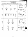
Clip and Fastener
•
•
Clips and fasteners in BT section correspond to the following numbers and symbols
Replace any Clips and/or fasteners which are damaged during removal or installation
Symbol
Shapes
No
@i)
fJ
Removal &. Inslallation
T i cv
Removal:
Remove by bend Lng up with
f1al -bladed screwdrivers or
clip remover
f~r'
SBF302H
SBF:l61B ....
~-,
®
9
~
lfwT~' ~
'--
Removel:
R"mOV9 Wlth a clJp remover.
r---
SBFJOJH
@.D
K
fOi
@)
u
11
i
i?
,
~
S8F423H
Push
e
C:J
...
Push center pin to /
calchlng position.
(Do '101 remove
center pin by hilling 11.)
lr: T...
Push
.0.
Installation,
SBF1C11lE
SBF25BG
Removel:
11
BT-3
r~'
Clip
FInisher
""SFSISB
SBF636C
GENERAL SERVICING
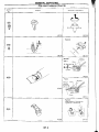
Clip and Fastener (Cont'd)
Symbol
Removal & Installation
Shapes
No.
MBFS1911
MBf520e
RemDval:
SBF10dB
Remove1;
Type 1
C1l Then oeM up
.. (;t.~~~~
il"
Push
Type2
SBf653B
SBF9\4B
Removel:
Holder porhon of clip must be
~pread oul to remOve rod
SBf7668
BT-4
SAF7708
GENERAL SERVICING
Clip and Fastener (Cont'd)
Symbol
Shapes
Removal & Inslallation
No
Removal,
1, Screw out with a Phillips
<@i)
i
@
i f
~~r 8fp
~ 1
~
~/
~
SBF076B
2
screwdriver.
Remove temale
portion wIth (,
flal·bladed
screwdriver [ ___~
J
n
i
I
~.
SBF992G
~
l·
C
L-
,.1
",'1"f
, I'
'I
BT-S
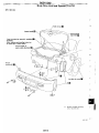
BODY END
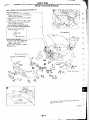
Body Front End
•
•
•
•
•
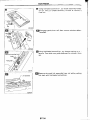
When removing or Inslal'ing hood, place a clOlh or other padding on hood. This prevents \/ellicle bOdy
rr om being scratched
Bumper fascia is made 01 plastic. Do not use excessive force and be sure to keep oil away from iI.
Hood ad: ustrnent Adj ust at hmge portion.
Hood lock adiustment: After adjusting. check hood lock control operation Apply a co.:!t (If grease to
hood locks engaging mecllanisnl.
Hood opener: 00 not attempt to bend cable iorcibly. Doing so 'lncreases ellart require(1 10 unlock
hood.
REMOVAL -
ill
('£1
@
@
®
®
(f)
®
®
@)
@
Front bumper assembly
Remove DOlts securing bumper li:1scia to engine undercover.
Remove screws and clips ~ securing left and right sides of front fender protector Then remove
the front fender pr()lectof.
Remove clips @ill) securing Iront grrlle, then remove the front grrlle.
Remove clip ~ securing bumper fascia bracket to hood lock stay
Remove screws located at wheel opening.
Remove the screw securing each side of fronl cle>arance lamp Dsscmbly. then remove the front
clearance lamp assembly.
Remove the screw securing each side of front turn signal lamp assembly. Then remove the fron~ turn
signal lamp assemb:y.
Remove bolts securing each side of front fender bracket.
Remove nuts securing left and right Iront fenders to bumper fascia bracket
Remove nuts and bolls securing bumper assembly to fronl side member.
Extract bumper assembly,
Remove bolls securing bumper fascia bracket to bumper fascia.
m
m.
@
@ Disassemble bumper tascia and bumper fascia brack.et
BT-6
j
se
c.
.....
•
,~
MO~!S:~~\
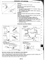
,at hood
Adjust
mesl,e,., .1 a
0059
• ,otter
When
10 \ 5
-
sec\J'lT1~ ~ood
Ie
'
onl d)
C
m,... (003Q to
arJj\Js\rre(\(, ad usl 0
c
urnper
\
not till SInker "'us, 00(.1<, ertSLJre
• ~7t:'rHa;'
ronl End
pnmary 10 k
\
~~D~~:rl<po,,""'''
man lender.
ruboer
•
Body F
250.'61.25' '6
••" ,
• 3.6,..6".630.6"'.147
II
does
l"'''\"'~ 1~~~'!lOn"'d at lhe
o~.'ale
IBtc~
1'1000
and ,.e~~,,~me,,' enSur. thai h(}()ll
'
r1 primary
Hood lock
ary locI<
seconaary
pr1>pe1..y.,gll>
hOoid"1l
l
r· ~o:.:"",
or. th.n 5.0 n1m {O.H1 In}
t~:ent
8umpef ",11M' ad
•
Adjust so thai
\er>d..., <\t that '1m IS ahgnell with
appro. 2 m
e deflection i
'<JOb "' (008 in)
5
t:l mm (0 51 ,~;, ;ree neigh' IS approt,
IElum~(
I~{~"
<II
~
BT-?
Bumper
N.no (kg.",samb'
II Ibr rrlCunllng bolls,
m
"ul~ a~d
clIps
BODY END
Body Rear End and Opener
•
•
•
•
•
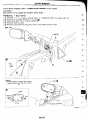
When removi ng or install ing trunk Iid, place a cloth or o~her padding on trunk lid _ Th is prevents
vehicle body from being scratched
Trunk lid adjustment: Adjust at hinae-trunk lid portion for proper :runk. liJ fit.
Trunk lid lock system adjustment: Adjust stnker 50 that it is In the center of the lock After adjustment.
check trunk lid lock operation.
Opener r.able· do not attempt to bend cable L'sirlQ e~ceSSI\ie force
After installation, make sure that trunk lid and fuel filler lid open smoothly.
REMOVAL -
Rear bumper assembly
G) Remove
® Remove
@ Remove
@) Remove
® Working
trunk trim. Refer to "TRUNK ROOM TRIM" in "INTERIOR TRIM" for details. (BT-21)
clips csm securing rear panel upper to bumper fascia_
clips CS101 securing rear panel lower to bumper fascia_
bOlts from lower side of each side bumper
inside trunk, remove nuts securing left and right rear fenders to bumper fascia [i1
(§) Extract bumper assembly II) .
----_._------
\~~
\~/J :;;
L
Fuei ',lIer t'd
apul\er & control
(OJ
BT-8
N·m (kg-m. f1-lbl
BODY END
Body R ear End and 0 pener (Cont':i\d)---- .SEC. 843-850
i.L
8T-9
•
•
For removal of door trim. refer to "DOOR TRIM" in "INTERIOR TRIM" lor details (BT-19)
After adjusting door or door lock. check door lock operalJon.
SEC. 800·803.805
r
Door g'.tu -topper
adjullmen!
I
l
Door
II'." slIb-channa' adlulIlmBnl
:- I~~
~
L
t
~/~13-16
~-t
~
(1.3 ·1.6, !I. 12\
~-,
"' 'Z
L
~
I
I~.-Door
~t6 .dlulIllNnl
~ .:~:u ·28
(2.1 ·2.9,15 - 21)
i(OJ1t. --'~
1l~
15
(1
t • 1.5, 8 -
____J
BT-10
_
(1.8 • 2.4. lJ· 17)
~ N-m (kg'" It·lbl
---------.-J
.l;IJ.
__
r~~~
-_/~~
Striker adlustment
~\\
~:.,'1
~~~18.2..
..::::=rr~)
I
HI" ••...., ••
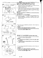
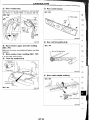
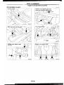
Door Glass Fitting Adjustment
The door glass is properly adjusted using the following five
methods:
In-oul adjustment (at the glass waiSI)
[;] Fore-aft tilt adjustment
[!J In-out tilt adjustment (at the glass Upper slop)
1!1 Up-stop adjustment
Fore-all adjustment
NOTICE:
When adjusting the door glass, it is nol necessary to remove
the outside door molding.
m
m
~1':Vl
Adjustm_ent locations
Front
L
Adjustment standard clearance
SEC. 803
t - 5 (0.04 . 0.20)
Weatherstrip
Afttalner hoiller
A
Front
o - 3.5
Secllon A -
(0.• 0.138)
A
=::=:j
~. Side window molding
-
Glass
Una. mm (in)
, --t-;5. 1.5 {O.1n • 0.2'95)
Sec110n B -
~
B
SflfJ94HA
..
- ~ ~ _ _----~------
8T-11
I
8..
DOOR
Door Glass Fitting Adjustment (Cont'd)
m IN-OUT ADJUSTMENT (at the glass waist)
Outside moldmg with
outer stabilizer
1.
Raise door glass until glass stopper is in contact with inner
stabilizer, just before the window stops.
2. Loosen adjusting bolts
3. Lightly press door glass upper end outward so that glass
outer surface contacts outer stabilizer. With glass held in
that position, press inner stabilizer to glass inner surface
and tighten adjusting bolt.
CAUTION:
Make sure nap portions of stabilizers are clean and free from
011. grease, elc.
Dutstae
@) FORE-AFT TILT ADJUSTMENT
rm-;:nt
•
1- ¢::JrhV'OdY';d'
/L~W".""'"
r.~
~
Adjust door glass sub-channel so thal the adjustment standard clearances A - A and B - B (Refer to BT-11) are
obtained at the glass and retainer holder/body side weatherstrip locations.
Door glass
sub-channel
MBF500B
r~u 2:J
R~
~<}
Upward
Door 111118& aub--chllnnlll
~
I
[!J
¢:' Correct
•
For sub-channel adjustment procedures, refer to figure at
left as a guide
CAUTION:
•
Make sure door glass sub~channel is horizontal.
• The fore-aft tilt adjustment musl be made at the same time
the fore-aft adjustment II Is made.
Downward
~
.&
¢' Incorrect
MBF501B
l!I
IN-OUT TILT ADJUSTMENT (at glass upper stop)
1.
Adjust door glass-Ie-holder clearance to 0 to 3.5 mm (010
0,138 in) (A) with the adjusting bolts
CAUTION:
•
Turn adjusting bolt clockwise 10 move door glass upper
end outward,
•
Turn adjusting boll counterclockwise to move door glass
upper end Inward.
•
For sub-channel adjustment procedures, refer to figure at
left as a guide
CAUTION:
•
Make sure door glass sub-channel is horizonlal.
• The fore-aft lill adjustment must be made at the same time
the fore-aft adjustment ~ is made.
BT-12
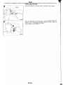
Door Glass Fitting Adjustment (Cont'd)
I!J
UP·STOP ADJUSTMENT
1
Adjust panel stopper height so that clearance at upper
edge of door meels the adjustment standard clearance
A - A (Refer to BT-ll). Make sure front and rear glass @/
stoppers lightly contact front and rear panel stoppers. then
tIghten adjusting nuts.
If stoppers do not contact each other, adjust sub-channel
nut. Refer to "fi] Fore-aft tilt adjustment",
Open and close doors to make sure upper end of door
glass does nol contact holder.
lower panel side
slopper [Upper
end of door glass
moves downward I
I
2.
Adjusting nut /
3
Glass s,de
stopper
(Front. Rear)
~
[;J FORE-AFT ADJUSTMENT
Fronl~
<:: ,./\,'
~
QRear
3
55.
loosen
Jock nuts
then adjust.
~
Gu><le (ail
L.----______
MBF!;04B
Adjust guide rail in lhe fore-aft direction so thai when door
is closed or opened the clearance between upper edge of ~(G
door glass and holder conforms to the .adjustment standard clearance A - A (Refer to 8T-11).
2 If ouler perimeter of door glass interleres with holder when Fia
door is opened or closed, refer to "Ii) Fore-an tilt
adjustment" for procedures.
CAUTION:
When loosening guide rail lock nut, prevent adJusllng bolt
from turning by holding It with a standard screwdriver.
3.
Lower the glass slightly until the glass side stopper comes
off the panel side stopper.
CAUTION:
Do not lower the glass excessively.
~ 1lI~CoN.O'' '!
Glass s,de stopper
After completing door glass adjustment, rellghten all lock
nutS.
CAUTION:
While lightening lock nuts, hold adjusting bolts using a standard screwdriver to prevent them from turning.
•
flat -bladed
...
" ~""~
~~~'(,
M8FOIlO.l\
BT-13
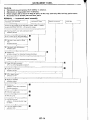
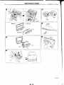
INSTRUMENT PANEL
CAUTION:
•
Disconnect ground terminal from battery in advance.
•
Disconnect air bag system line in advance.
•
Never tamper with or fOfce air bag lid open, as this may adversely affect ai, bag performance.
•
Be careful not to scratch pad and other parIs.
REMOVAL -
Instrument panel assembly
I
Audo &
A/CCO~
Remove air bag module (driver] and steenng wheel Rerer to "' SlJPPI F.
MtN" A\. RESTRAINT S'iSTEM"' In AS secl,on lor de\~lls
(D SIl?~Tln9
J
-------------'---------
column cover and comlJlnalloll sWlIcn
• AemOlle scr(!W$
'----~-_-_-----TI-------------~--
@
I~
1
A,'T iinisher or MiT shiH
In.l,um,,,,' low,,'
side
•
~r
\~er bools
m
On drive'
Remove screws
I'@ Instrumen! lower reinforcement
1_ •
<ID
I
Remove
bol'"
Cluster lid A
• Remoll'! screws :hen disconnect harness conneclors
~~ ~nTlbH'\al.. t:<n mmQf
• Remove .crews then disconnect harness conr>eclors
r----
o
T
- - .- - - - . " - - - . _ - - - -
Ceol@r ve,,"ilat;orl assemblt
• P,J II oul wah a r1al·l>laded sc' ewdflver_
~oo
--~~
-- -----==c
(!'i Ale or healer conlrol
• Rp,movp. ,,-:rf'wc;.
---r-l~--~~-
I
®
Glo~e bo~ ~;sombly
• Hemove serews
BT-14
I
Glove box
SEC. 241l.487·680·685·969
~[!
~~
~~~
l.~
~t
iJ"E
,t11jn
/~'.~!
,~l}
,l'ffi!,
•
ll'sl'umel'll panel
ass~mbty
flIOUrltlnq bolts and nuts
f.l.t~\
pj~
~T
rl~
Mell.' cUp
INSTRUMENT PANEL
MBr52~B
8T-16
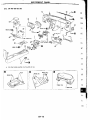
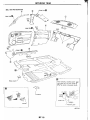
INTERIOR TRIM
SiDE AND FLOOR TRIM
CAUTION:
Wrap tl1e tip of f1al·bladed screwdriver with a clolh when removing metal clips from garnishes.
REMOVAl- Body side trim
(f) Remove front and rear seat Refer to "SEAT" tor details (8T-27),
Remove dash side finisher,
®
®
Remove kicking plate.
@ Remove front pillar garnish.
@) I1cmove rear side finisher.
® Remove rear pillar finisher,
®
Remove rear parcol shelf
®
welt. Refer to "TRUNK ROOM TRIM" for details (8T-21)
Remove seat back finishers (Right. Center, Left).
® Remove seat back finisher
BT-11
~,:~1r/~~1J. IJ-~~
<:::>
.-~ J
-r.-.-.-I
Heater un,i
J
~
~
-~--
f-------, _
Carpe
Instrument pan",1
BT-18
-_
DOOR TRIM
REMOVAL - Door trim
[l Remove screws securing inside handle escutcheon, then remove the inside handle escutcheon
m'
®
m.
Remove power window switch
@ Remove screws securing door finisher
@ Remove clips (@ securing door finIsher,
® Pull door finisher to remove clips @) and metal clips [!J from door panel and remove door finisher Disconnect harness connectors,
® Remove ventilator grille and ventilator duct assembly from door finisher I!]
SEC. B09
@ir,
~liI/~,
~11t!l
vc;
'---------------- '-------_._----- '-------------
81-19
TRUNK ROOM TRIM
SEC 799·849
Well
~J
~
8T·21
Mel.1 clip
m
MBF449B
BT-22
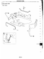
EXTERIOR TRIM
rID @
(1) Windshield upper and side molding
I
~
Cowl top grille and hOOd rear
sealing rubber
SEC. 660
Method 1
~;-:v
~\~c,~''''''"•
Appl~
/~~~--
LCOWIIOP~@ /~
.
•
..
<§I>
~J~/~''''
,ulan, to top pOll,on 0/
mold,ng
L
Cut all low~t jlO't,on •
of new mold."~
MBF450B
------.J
...
@.
®
Hood fronl sealing rubber
SEC. 650
F HUlk well 10 gIve it a
good i!lppearanc.e
Method 2
1. Cut off sealant at glass end.
2. Clean the side on which panel was mounted.
3. Set molding fastener and apply sealanl to body
'~:. T
panel. and apply primer to molding and body.
- Double·bee<!
lIdhe"Vi! tape
MBfJ5111
4
Install molding by aligning the molding mark
located on center with vehicle center.
Be sure to install tightly so that there is no gap
around the corner.
(~
Body side well
SBF'6\F
Outs,(l~
MBF452B
IG.
BT-23
EXTERIOR TRIM
,..,
I.U
I
@ Body side
.
weath erstnp
. and
atner
SEC. 766
weatherstrip ret .
Retainer
w""
~~o«.m,
\:
Body sIde
weatherstrip
MBf45J8A
BT-24
....
EXTERIOR TRIM
®
Door weatherstrip
@
Before removing door weatherstrip, remove door
trim Refer to "DOOR TRIM" lor details (BT-19).
Rear panel finisher
SEC, 265
SEC. 800
If
L-
MBF4s.tB
® Back window upper and side molding
(SEC. 797)
Basically the same as windshield upper and side
molding
@ Back window lower molding (SEC. 797)
It is mounted with screws,
@ Trunk lid weatherstrip
'
1¢
" / Trunk I'd
,'"wealtlerSlr,p
~O
Butyl
seal
.
MBF456BA
_
@ Sun roof lid weatherstrip
SEC. 736
l:t~l
~
Body panel
MBF<!S7BA
p:o:
EXTERIOR TRIM
@
Rear combination lamp
------------------- ------
,com ~ ",
I
l
I
Heal gun
~~-
~-~---<;'~- (\\\'\ ~~
~~
jllm~\\(LJ
~~~-"-\1~ I \
-----------:::
----
L,.'....
)
~
()l
Butyl seal
II
\
• Wnrm up lamp lISJembly a"'8 to a tempereture n IIttl"
'0
• Apply butyl seol evenly •• II tellds 10 b.. "om~ thin I" th ..
corner._
• Warm up ramp lIllSembly nrea to s temperature a lillie
below 60"C (HOOF).
,'wo.
MGf459B
@ High-mounted stop lamp
81-26
.
carefully han die it to keep dirt out an d avoid damage.
.
the seat trim.
or installing
.
von
•
When 'emo
9
Front Seal
SEC. 870
,I
L.-=r
t
L_-----~~
BT-27
r:oJ ',(4. .S:~ ..u, 32 - 41)
J
43
Front Seat (Cont'd)
Remove retainer from lower side of seatback with fingers
MBF494B
Roll up seatback trim all the way to gain access to headrest
holder pawls Disengage and push headrest holder pawls to
unlock holder lift off headrest holder.
[-~_-
MBF495B
8T-28
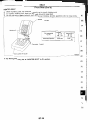
Front Seat (Cont'd)
HEATED SEAT
•
•
•
When handling seat, be extremely careful not to scratch healing unIt
To replace heating unit, seat trim and pad should be separated,
Do not use any organic solvent. such as thinner, benzene. alcohol. gasoline. etc_ to clean trims.
--,'--- ,---,---'--"---/
Se~tback trim ~"d
~~
pad
Trim lemperature
0C (oF)
Increasing 10
DecreaslIlli' 10
35 ' 45
25·35
/95· \131
(77 " 95)
Turns OFF
Turns ON
f-----
Thermos18t operation
(C!L.
ijIT
MBF332B
DiY
* For Wiring Diagram, refer to "HEATED SEAT" In El section.
~m
,r$).
~&:
~I~J
~'jj'
'R1~
BT-29
Rear Seat
SEC. 880
Striker installallon
a
A
Nom (kg.m, 1l·lbl
MBF461 SA
BT-30
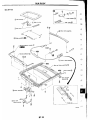
SUN ROOF
* For Wiring Diagram, refer 10 "ELECTRIC SUN ROOF" In EL section.
ADJUSTMENT
Inslall motor & limit SW assembly and sunroof rail assembly in the following sequence:
1.
2.
3.
4.
5
6
7.
8
9.
Arrange equal lengths of link and wire assemblies on both sides of sunroof opening.
Connect sunroof connector to sun roof swi tch and positive ( +) power supply.
Set lid assembly to fully closed position
by operating OPEN switch and TILT switch.
Fit outer side of lid assembly to the surface of roof on body outer panel.
Remove motor, and keep OPEN switch pressed until motor pinion gear reaches the end at its rotating range
Install motor.
Check that motor drive gear fits properly in wires.
Press TILT-UP switch to check Iid assembly for normal tilting.
Check sunroof lid assembly for normal operations (tilt-up, lilt-down, open, and close).
m
SBF92QF
81-31
SUN ROOF
•
After any adjustment, check sun roof operation and lid alignment.
•
Handle finisher plate and glass lid with care so not to cause damage_
•
It is desirable tor easy installatIOn to mark each point before removal.
CAUTION:
Always work with a helper.
r
Link and
I aSSembly
w"~=:J
Sh ada
Sun rool trame
as~embly
L,d assembly
assembly
--=r==
~ass I'dup
___------'-
==r=___
~
I
(1) S'oe trim
~
• Rl>mol/e s'de t'lm clIps
------..-J-_ _
- _~-_-====:r=
~-sun
'001 11<1 mour.1 nvls
==r==----~
----
l~emb\Y
=r=
I ~)
Aaa! dram moun! screws
[,~
Reay d/ain
-==r=
-----r==--------=r
assen\~ly
~~e sun rool switch to 1"1 glass lid down
i IID
==r=
~
~
:=r:::=-------,
--==::L
~_=r==
-----=r:=
I
..::::::r=
====:I
t
~
I
_ _------'1
Shade assembly
_
]
==r=
I
_
m
Sun ,oat switch/,nl""", accessories/headlining
• ReIer to "ROOF TRIM \IH-20)_
===r:
I
(7)
MOlor sw,tch
~
b'ac~el
--=r:::::==
I~
--==::L
_
Molor assembly
[\ID w,nd~w
-----=c=J om----._----.
dellector hO-ld-e-r
---J------
L!:
I
J
Wmdow deffeeln! moun! sCrew
--J
-~----r--
~
W",dow deHector assembly
J
l: Dra~~s=-=-~
@
[
~:i)
'Rl
!
(15\ GUide
r
'ii) Rear
Sun 'oaf frame assembl)'
-=r=.
]
~
~,nk
I
I
'IO"P~
g~l
~-----.::r
I
I _
==-r=-
,-----c==
'I
I
=r=-
Sun roof un,l b'aLk"il
~----l
and w""
. ;ssemblV
---J
I
1.---------
BT-32
I
SUN ROOF
SEC. 264· 736
1m.
o
t
F'on\
1f
I
.!h-~~
-
~C~ ,~ "J
~,--
-- Gu!de Slopper @
Rea' gUide@
SBTOO)
BT-33
I (1';"
SUN ROOF
m Using flat-bladed screwdriver, pry shade assembly holder
011 rail Then pull shade assembly forward to remove it
from rail
mDisengage pawls trom rail, then remove window deflector holder.
mUsing flat-bladed screwdriver, pry stopper spring off rail
groove. Then slide rear guide backward to remove it from
rail,
mRemove wire and link assembly from rail while pushing
link back with flat-bladed screwdriver,
t.1BF493B
BT-34
REMOVAL
After removing moldings, remove glass.
CAUTION:
Be careful not to scratch glass when removing.
INSTALLATION
•
-I/O
J
, ',\.',
/
\''\\
SBFOJ48
--------
Use genuine Nissan Sealant kit or equivalent. Follow
Instructions furnished wIth It.
After Installation, Ihe vehicle should remain stationary
•
untH Ihe sealant hardens.
WARNING:
Keep heal and open flames away as primers are flammable.
CAUTION:
Advise users not 10 drive the vehicle on rough roads until
sealanl has properly vulcanized.
•
Do not use sealant which Is past its usable term.
•
Do not leave cal1ridge unanended with its cap open.
•
Keep primers and sealant In a cool, dry place. Ideally, they
should be stored in a refrigerator.
•
Molding musl be installed securely so that it IS in position
and lea\les no gap.
~E
Windshield and Rear Window
Inslall dam rubber.
Windshield
1\
1==f~
'
);j
DMh upper panel
8 - 9 (0.31 - 0.35)
~j..©
~j
[
~.~
~,~'II
8. 9
8 - 9
\
(0.31 - 0.35)
Joint portion
Glass
Rear wlndow
61~
f=
(0.31 • 0.35)
@ J o i n t portion
425 (16.73)
'iDS (15.94)
Reef wlndow
B
- 9 • O.JS) ~eh'c1e center
(0.31
8(0.31
. 9 • 0.35)
Tjehicle
8 _ 9cenler
(0.31 - O.35)
Dam rUbber~GlaSS
Double·/aced adheswe tepe-
8 • 9
Body panel
(0.31 - 0.35)
Unit: mm r,nl
Apply sealant 8¥enly.
WIndshield end rear wlndow
Inslall molding lastener.
When installing it. heat body panel and
fastener 10 approx. 3(J to 40°C (86 10 104°FI,
3f ~7
- 8 (0.28 - 0.311
Upper & side molding fasteners
.e
~
vF8SIener
Dam rubber
....
panel~
~
~"
-
)!.:.•>
I-
Glass
:>:::._~
Double·faced adhesive tape
~
MBF4638
.
Unit mm lonl
MBF464B
REPAIRING WATER LEAKS FOR WINDSHIELD AND WINDOWS
Leaks can be repai red WI thoul removing and rei nstall ing glass,
(fti:l
If water is leaking between caulking material and body or glass, determine the extent of leaking. This
can be determined by applving water while pushing glass outward.
To stop the leak, apply primer and then sealant to the leak point.
81-35
WINDSHIELD AND WINDOWS
Side Window
SEC. 830
Seiliant quantity
ill:
12 -
1~
-r--=r---
c-
7 ·8
lQ.26 . 031~ Umt: mm (in)
BT-36
DOOR MIRROR
*For Wiring Diagram. refer to "POWER DOOR MIRROR" In EL section.
CAUTION:
Be careful not to scratch door rearview mirror body.
REMOVAL -
Door mirror
CD
Remove door trim HeIer to "OOOR TRIM" in "INTERIOR TRIM" for details (8T-19)
® Remove inner cover front corner of door fi1 .
@ Disconnect door mirror harness connector.
@ Remove harness clips
t]) Remo\le three bolts securing door mirror, Illen remove door mirror.
SEC. 963
~-==::::=:::=:::--
Remove•
• Wlap nal-hladllo <:J scre....driver "";ltl a cloth to
pr81lent seratchilly ,ea, 0' door mirror. 00 no!
insert screwdriver too tal
91-37
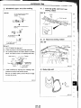
FRONT AND REAR AIR SPOILER
•
•
When installing, make sure that there are not gaps or waves at ends of air spoiler.
Before installing spoiler. clean and remove oil from surface where spoiler will be mounted.
Front Air Spoiler
SEC. 960
Rear Air Spoiler
SEC. 960
\~-
-~
~ lt~~o
,~ ~~
~::
I,
~
~~~~~~J
-- ®
\ (e-Y)
\\...-.-:: ...-:::::--
~
_
V'~"'~~l7
""J~
-Double-faced adhesive tape
BT-38
2
Sealing 'ubbe'
BODY ALIGNMENT
•
•
•
•
•
•
All dimensions indicated in figures are actual ones.
When using a tracking gauge, adjust both pointers to equal length. Check the pointers and gauge
itself to make sure there is no free play.
When a measuring tape is used, check to be sure there is no elongation, twisting or bending.
Measurements should be taken at the center of the mounting holes.
An asterisk C") following the value at the measuring point indicates that the measuring point on the
other side is symmetrically the same value.
The coordinates of the measurement points are the distances measured from the standard line of
"X", "Y" and "z",
z
(+)
Imaginary base line
"Z": Imaginary base line
[200 mm below datum line
("Or at design planl]
C@ : LH
sIde
CffiD : RH side
y
/H
-
:'C. ~,
Front ule center
(0)
Engine Compartment
MEASUREMENT
II
623
Unit: mm
I
L-
MBF376B
._-----.---.--------------
BT-39
BODY ALIGNMENT
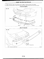
Engine Compartment (Cont'd)
MEASUREMENT POINTS
Unit: mm
----
--
o
Front
Radiator core support upper
and side
@ /
~
MBF473B
Radiator core support lower
7 die.
·_-------~--I
o
0
ii:'
8
1_
,H, . .
dl·,l._--L.°_---'--
----...--
_
MBF471 B
BT-40
__ 1--------------
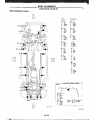
BODY ALIGNMENT
Underbody
MEASUREMENT
...
IG
Q)
E
a:
¢~
jy
.i:
CD
c(
---1
E
~
::)
350
350
®
350
g\~:
~~,
2&3
805
@(~'
@(ci:!
-:- L'
,-
(102)
115
154
104
6)(:3
®C~l
@r§)
Q)
¢~
..
...J
~
_-+----73-1__ (~} §.
255
@(~:'
..
0>
~
....
co
u:
co
u:
M8F375B
BT-41
(-
BODY ALIGNMENT
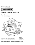
Underbody (Cont'd)
MEASUREMENT POINTS
Rear
V
Front
coordi nates:
Rear
coordinates:
@,@
@
G ..m·
ID
X : 378
y : --635.5
Z : 214.5
X : 422.5
: 1,650
Z : 103.9
@, (~)
@,@
X : 185.3
X : 564
y
y
: -630
Z : 179
Y
: 1,900
Z : 154
@,(C)
G),CD
X : 370
X : 540
y
y
: -196.5
Z : 254.9
: 2,100
Z : 115.2
@.@
®.®
X : 384.2
Z : 254.9
X : 308
: 2,690
Z : 262.8
@,@
©
y
y
: 32
X : 380
y : 510
Z : 106.2
X : S40
: 2,955
y
Z : 350
®.(D
CD
X : 420
; 1,150
Z : 106.2
X
y
RH side
c)
: soo
y
: 2,955
Z : 350
~
X : 580
y : 3,245
Z : 350
@
X : 530
y : 3,250
Z : 350
Front and rear strut tower centers
I
~-w-,
Coordinates:
®,(PJ
X : 545.1
Y
Z
: 63.6
: 730.9
@.@
X : 479.8
Y : 2,608
Z : 804.6
Front:
Rear:
®. @
@. ®
82.2 dl•.
66 die.
Unit: mm
Front
MBF477BA
BT-42
m
-
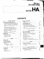
HEATER &
AIR CONDllllONER
@f
SECTION
HA ~j2
CONTENTS
1=
.1
MANUAL AND AUTO
L __
TROUBLE DIAGNOSES
-...--J
... 3
PRECAUTIONS AND PREPARATION
Supp Iemental Res tra; nt Syste m (S RS) "A' R
BAG" and "SEAT BELT PRE-TENSIONER" ....... :.... 3
,.. 76
Contents
,
Wiring Diagram -
,
A/C, A -
127
Overview of Control System
Control System Input Components
··
3
COlltrol System Automatic Amplifier (Auto
General Refrigerant Precautions
3
Precautions for Refrigerant Connection
4
amp.}................
Control System Output Components
Precautions for Servicing Compressor
5
Special Service Tools
5
,
6
Precautions for Service Equipment
"
8
DESCRIPTION
Refrigeration Cycle
'
Component Layout..
10
10
,
,
Discharge Air Flow
'-_-------=:1-
"
..
_ _ _~J
DESCRIPTION
Introduction
Features
Control Operation
13
13
'
TROUBLE DIAGNOSES
Contents
Wiring Diagram Wiring Diagram -
12
c=~- ::=J
MANUAL
DESCRiPTION.......
Control Operation
..
,........
14
14
..
HEAT A/C, M _
AUTO
11
37
.45
:===J
[
72
72
.
,
--
72
73
'------_ _-----.J:I
.Ic;t
104
SYSTEM DESCRIPTION
Precautions for Working with HFC-134a (R134a)
HFC-134a (R-134a) Service Tools and
Equipment
76
127
128
...130
130
MANUAL AND AUTO
SERVICE PROCEDURES
"
"'-,
~'r.;
-:;/~".
"
138
138
HFC-134a (R-134a) Service Procedure
Maintenance of lubricant Quantity in
Compressor.........................................
Refrigerant Lines
·
C ompressor M ountlng
Belt Tension
~j
.
140
142
4
14
~~~;
144
Fast Idle Control Device (FICO)
"
144
Compressor - Model DKV-14C (ZEXEL make) .. 145
c---~
l-I~_~~-==:J ~~~~
MANUAL
SERVICE PROCEDURES
..
Overhaul - Push Control Unit Assembly ..
Disassembly
'---------
--JI
--
.
MANUAL AND AUTO
SERVICE DATA AND SPECIFICATIONS (50S).
General Specifications..
Inspection and Adjustment
... 148
148
.148
=:=J
149
..149
149
f{L