1
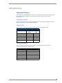
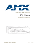
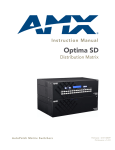
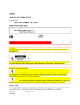
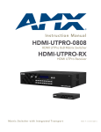
Instruction Manual
CP-15
Control Panel
AutoPatch Control Panel
Release: 2/14/2008
Contents
Contents
Introduction.........................................................................................................1
Applicability Notice ................................................................................................................. 1
Overview ................................................................................................................................. 2
Key Functions .......................................................................................................................... 2
Menus & Modes....................................................................................................................... 5
Executing Switches..............................................................................................7
Changing the Virtual Matrix ................................................................................9
Disconnecting Switches .....................................................................................10
Verifying Signal Status ......................................................................................12
Executing Presets ..............................................................................................13
Global & Local Presets........................................................................................................... 13
Executing Local Presets ......................................................................................................... 14
Defining Global Presets......................................................................................................... 15
Executing Global Presets....................................................................................................... 16
Adjusting Audio.................................................................................................17
Adjusting Output Volume...................................................................................................... 17
Muting & Un-Muting Outputs................................................................................................ 19
Adjusting Digital Input Gain .................................................................................................. 20
Locking & Unlocking..........................................................................................22
Locking the Control Panel ..................................................................................................... 22
Unlocking the Control Panel.................................................................................................. 23
Setting the Password ............................................................................................................ 23
Setup Options ...................................................................................................24
Checking the Software Version ............................................................................................. 24
Choosing the Default Virtual Matrix ...................................................................................... 25
Reloading the Configuration File........................................................................................... 26
Installing a CP-15 Remote Control Panel...........................................................27
Connecting to an AMX AutoPatch Router ............................................................................. 27
Applying Power ..................................................................................................................... 29
Rack Installation..................................................................................................................... 30
Linking Multiple Panels.......................................................................................................... 31
Completing the Installation ................................................................................................... 32
Appendix A – System Error Codes ....................................................................33
Technical Support.................................................................................................................. 34
CP-15 Instruction Manual
i
Contents
ii
CP-15 Instruction Manual
Introduction
Introduction
Applicability Notice
The information in this manual applies to the CP-15 Control Panel, which comes with many of the
Optima pre-configured systems or can be ordered as a remote control panel or as part of a
custom system.
Pre-Configured Systems
The CP-15 can be part of an Optima pre-configured system. All Optima pre-configured systems are
numbered FGP46-xxxx-xxx (e.g., FGP46-0808-34B).
Custom Systems
The CP-15 can be ordered as an option for Optima 2 RU and 3 RU custom systems.
Control Panels for Custom Systems
Configuration Size
Control Panel Sales #
2 RU
3 RU
8x8
FG1046-261
FG1046-240
16x16
FG1046-258
FG1046-237
16x24
FG1046-255
FG1046-234
20x20
FG1046-249
FG1046-216
24x16
FG1046-252
FG1046-231
36x4
FG1046-246
FG1046-210
Remote Control Panel
The CP-15 Remote Control Panel can be ordered as a separate unit to control an Optima,
Precis 500 MHz, Modula, or 8Y-3000 system.
Remote Control Panels
Configuration Size
Control Panel Sales #
8x8
FG1090-276
CP-15 Instruction Manual
16x16
FG1090-273
16x24
FG1090-270
20x20
FG1090-267
24x16
FG1090-264
36x4
FG1090-261
1
Introduction
Overview
The CP-15 is used for controlling the system’s switches and system attributes. Although
control panels are optional, we recommend one per system for system verification,
redundant control, and troubleshooting.
FIG. 1 illustrates an Optima Distribution Matrix with a CP-15 Control Panel. Other models may vary
slightly in appearance.
Power Indicator
FIG. 1 CP-15 Control Panel on an Optima
Note: AMX AutoPatch enclosures can also be controlled using BCS (Basic Control Structure)
commands transmitted through an external controller; for more information, see the
BCS Protocol Instruction Manual on the AMX AutoPatch CD or at www.amx.com.
A CP-15 Control Panel has an LCD, a Function Key, a Control Dial, a Select Key, a Cancel Key,
a Take Key, Input and Output Keys, and a Power Indicator.
The Control Dial and Select Key work together for scrolling through the menus displayed on the LCD
to place the system into various modes (the types of operations, e.g., Change Mode) or to access lists for
control operations. Once in the desired mode, use the Input and Output Keys to select values and the
Take Key to execute the operations (some modes require using the Control Dial and Select Key
to select values).
Key Functions
Control Dial
Function Key
Select Key
Input Keys
LCD
Cancel Key Take Key
Output Keys
FIG. 2 CP-15 Control Dial & keys
Function Key
The Function Key accesses the Function menu on the LCD. As the Control Dial is turned, this menu
displays the various command options, e.g., Status, Disconnect, etc. The Function Key can be pressed at
anytime to return the display to the Function menu. For an overview of menu options, see page 5.
2
CP-15 Instruction Manual
Introduction
Control Dial
The Control Dial scrolls through menu options and adjusts values, such as volume. The Control Dial
is used in conjunction with the Select Key to choose commands and values on the LCD.
Select Key
The Select Key enters a selection. In addition, the Select Key can be used to execute presets;
however, the Select Key cannot execute or disconnect switches. Pressing the Take Key executes
or disconnects switches.
Cancel Key
Pressing the Cancel Key clears an incomplete operation and returns the display to the beginning of a
submenu or list. The Cancel Key cannot undo a completed operation, i.e., an operation followed by the
pressing of the Take Key. If the Cancel Key flashes, an error has occurred; a flashing Cancel Key must
be pressed before continuing.
Take Key
The Take Key functions much like the Enter Key on a computer keyboard. Pressing the Take Key
instructs the system to execute or disconnect a switch. Prior to pressing the Take Key, the individual
operation component(s) are selected by pressing the appropriate key(s).
Input & Output Keys
Input and Output Keys correspond to the input and output connections on the rear of the enclosure.
These keys are used to select the inputs and outputs for routing source signals to destination devices
as well as for status and audio operations. Input Keys are also used for locking and unlocking the
control panel.
When an Input or Output Key is pressed, the channel name displays on the LCD. Hold the key down to
display the name longer. The default channel name (e.g., O_Ch:0003 for Output 3) appears unless the
name has been modified in the configuration file* using XNConnect. While XNConnect allows for the
creation of channel names up to 24 characters long, the CP-15 displays only the first 20 characters.
FIG. 3 Example of a custom channel name
* The configuration file (.xcl file) contains routing and control information for a system and is modified
with XNConnect, which graphically displays the configuration file. Both the configuration file and
XNConnect are on the AMX AutoPatch CD.
CP-15 Instruction Manual
3
Introduction
The Input and Output Keys illuminate depending on the mode (the type of operation) the CP-15 is in:
Blue key – indicates that it can be selected as part of the current operation.
White or flashing white key – indicates that it has been selected and that further action is
required to complete the operation. A white key can also indicate routing status. When
a key is flashing, it cannot be unselected and does not display label information on the
LCD when pressed.
Non-illuminated key – is not available for the current operation, e.g., Input Keys are
unavailable when the panel is in Output Volume Mode.
FIG. 4 shows various keys states while in Change Mode. Input 9 is flashing white, indicating that it was
selected first. Outputs 3 and 13 are white, indicating that they have also been selected (and can be
unselected). The switch from Input 9 to Outputs 3 and 13 will be executed when the Take Key is pressed.
Note that Inputs 18, 19, and 20 are not available.
Selected Key
Flashing
Available Key
Selected Keys
Unavailable Keys
FIG. 4 Example of key states during Change Mode
4
CP-15 Instruction Manual
Introduction
Menus & Modes
The Function menu and its submenus access the different modes and lists used to control the system. The
modes are Change, Disconnect, Status, Output Volume, Mute, Input Gain, and Lock. While in a mode,
the same type of operations can be performed, e.g., when in Mute Mode you can select various outputs to
mute and un-mute without having to repeatedly put the CP-15 into Mute Mode.
This section provides an overview of the menus and modes. Detailed information and instructions on the
individual modes are provided in the remaining sections.
Use the Control Dial and Select Key to navigate the Function menu, submenus, and lists. The menus are
loop menus, which means that each menu returns to the first item after you scroll past the last item.
The Function menu (FIG. 5) and its submenus access the following
modes and lists:
Change
Selecting Change places the system in Change Mode. The CP-15
must be in Change Mode to execute switches. While in Change Mode,
select the Input and Output(s) Keys followed by the Take Key to
execute switches (see page 8).
Virtual Matrix
Selecting Virtual Matrix accesses the list of virtual matrices that are
defined for the system. This list is used for changing the virtual matrix
on which operations will be performed (see page 9).
Status
Selecting Status places the system in Status Mode. While in
Status Mode, signal status can be verified to confirm correct routing
or routing to multiple outputs without risk of accidently executing a
switch (see page 12).
FIG. 5 Function menu structure
Disconnect
Selecting Disconnect places the system in Disconnect Mode. While in Disconnect Mode, select the Input
or Output Key(s) followed by the Take Key to disconnect switches (see page 10). While in Disconnect
Mode, the CP-15 does not indicate the current routing of selected inputs or outputs.
Setup Options
Selecting Setup Options accesses the Setup Options submenu to check the Software Version, change the
Default VM (Virtual Matrix), or Reload Config file (see page 24).
Lock Panel
Selecting Lock Panel places the panel in Lock Mode at which time the password is entered to lock the
panel. Locking the CP-15 limits access which can prevent accidental switches (see page 22).
Adjust Audio
Selecting Adjust Audio accesses the Adjust Audio submenu. From this menu you can place the panel in
Output Volume Mode, Mute/Unmute Mode, or Input Gain Mode (see page 17).
Global Preset
Selecting Global Preset accesses the Global Preset submenu to Define Global Presets or Execute
Global Presets (see page 15).
CP-15 Instruction Manual
5
Introduction
Local Preset
Selecting Local Preset accesses the list of local presets that can be executed (see page 14). Local Preset
will only appear as an option on the Function menu if local presets have been defined in XNConnect for
the selected virtual matrix.
CP-15 Control Panel operations combine the following four basic tasks:
To choose a mode, submenu, or list – Press the Function Key to access the Function menu.
Use the Control Dial and Select Key to choose the desired mode, submenu, or list.
To select inputs or outputs – Press the corresponding Input or Output Key. Selected keys will
change color or flash, depending on the routing state.
To select values for fields (such as virtual matrices, volume, or preset values) – Use the
Control Dial and Select Key.
To execute a command – Press the Take Key.
6
CP-15 Instruction Manual
Executing Switches
Executing Switches
A switch is an active connection between an input (source) device and one or more output (destination)
devices. The signals routed in a switching operation are individual signals or groups of individual signals
coming through the connectors on the rear of an enclosure. Executing a preset is a quick way to execute
multiple switches at a time. For information on presets, see page 13. Switches are executed on the
default virtual matrix unless otherwise specified. When specifying a virtual matrix, be sure it includes all
the signals you want to route. The number of the virtual matrix (VM) that operations are currently being
performed on is displayed in the upper-right corner of the display.
Virtual matrix definitions reside in the configuration information in each enclosure’s CPU. If you need to
change the virtual matrix, see “Changing the Virtual Matrix” on page 9. If you decide to change the
default virtual matrix, see page 24 for “Setup Options.”
You can execute switches from the CP-15 using the steps on the following pages or by executing a local
or global preset (see page 13).
When an Input or Output Key is pressed, the channel name displays on the LCD. Hold the key down to
display the name longer (FIG. 6). The default channel name (e.g., O_Ch:0003 for Output 3) appears
unless the name has been modified in the configuration file using XNConnect (see the Help file). While
XNConnect allows for the creation of channel names up to 24 characters long, the CP-15 displays only
the first 20 characters.
You can return to the Function menu at any time by pressing the Function Key.
FIG. 6 Example of a custom channel name
Note: When you put the panel in Change Mode, available keys will be blue and any unavailable
ones will not be illuminated. The first blue key selected flashes white and the next key(s) selected
turns white. You can toggle the non-flashing white keys between the selected (white) and unselected
(blue) state before pressing the Take Key. For more information, see page 4.
In an execute switch command either an input or an output can be selected first. To switch to multiple
outputs, the Input Key must be selected first. With the CP-15 you can select and unselect Input and
Output Keys to modify the switch as long as the keys are not flashing. Once satisfied with the switch
selections, press the Take Key to execute it.
For new installations, we recommend that before attaching all inputs and outputs, you perform a test
switch routing Input 1 to Output 2 on the level designated by the enclosure’s “Connector Guide”.
Depending on the signal type (e.g., component signals), you may need to attach multiple input and
output connectors.
CP-15 Instruction Manual
7
Executing Switches
The example below switches Input 2 to Output 1 on the currently selected virtual matrix.
To execute a switch:
1.
Press the Function Key.
The Function menu appears.
2.
Press the Select Key to choose Change.
The system is in Change Mode (the available Input and Output Keys turn blue).
Current VM
8
3.
Press Input Key 2.
Input Key 2 flashes indicating that it is ready to switch.
(Any outputs currently connected to Input 2 will turn white).
4.
Press Output Key 1.
Output Key 1 illuminates indicating that it is ready to accept the switch.
5.
Press the Take Key.
Input 2 switches to Output 1, and the keys turn blue.
The panel remains in Change Mode until the Function Key is pressed.
CP-15 Instruction Manual
Changing the Virtual Matrix
Changing the Virtual Matrix
Virtual matrices are defined in XNConnect and stored in the system’s configuration file (see the
XNConnect Help file). Systems usually have a virtual matrix that contains all signals, so that any input
can be routed to any or all outputs. The same system may have other VMs that switch only audio signals
or only video signals.
Occasionally you may need to execute switches (or other operations) on a virtual matrix other than
the current virtual matrix. Changing the virtual matrix does not change the default virtual matrix. The
system will revert to switching on the default virtual matrix when the power is cycled. For information
on changing the default virtual matrix, see page 25.
The directions below give the steps for changing from routing signals on Virtual Matrix 0
“Audio/Video” to routing on Virtual Matrix 2 “Audio, Stereo.”
To change the virtual matrix:
1.
Press the Function Key.
The Function menu appears.
2.
Locate Virtual Matrix by scrolling with the Control Dial.
3.
Press the Select Key.
The V. Matrix list appears.
Current VM
4.
Scroll to 2:Audio, Stereo.
5.
Press the Select Key to enter your selection.
The display returns to the top of the V. Matrix submenu.
VM 2 becomes the new virtual matrix used for all operations.
6.
Press the Function Key to return to the Function menu.
The system is ready to make changes on Virtual Matrix 2 “Audio, Stereo.”
The system will remain on Virtual Matrix 2 for all operations until the virtual matrix is changed or
the power is cycled.
CP-15 Instruction Manual
9
Disconnecting Switches
Disconnecting Switches
Disconnecting a switch deactivates the connection between an input (source) and one or more output
(destination) devices. Disconnecting an input disconnects all outputs currently receiving that source
signal. An output can only be connected to one input; therefore, disconnecting an output will only
disconnect the connection between the output and the input that is routed to it.
You can disconnect a switch by selecting either inputs or outputs from the CP-15 Control Panel. Inputs
and outputs can be selected in the same disconnect command.
Although switches can be disconnected when in panel is in Change Mode, the advantage of using the
Disconnect Mode is that it can be used to quickly disconnect multiple outputs receiving a signal from the
same input (by disconnecting the input) or from different inputs (by disconnecting the outputs).
If you need to change the virtual matrix, see “Changing the Virtual Matrix” on page 9.
You can return to the Function menu at any time by pressing the Function Key.
Note: When you put the panel in Disconnect Mode, available keys will be blue and any unavailable
ones will not be illuminated. When you select a blue key, it turns white. You can toggle the keys
between the selected (white) and unselected (blue) state before pressing the Take Key. For more
information, see page 4.
Once the CP-15 is in Disconnect Mode, inputs and outputs can be selected and unselected by pressing
the corresponding Input and Output Keys. The disconnect command is not executed until the Take Key
is pressed.
While in Disconnect Mode, the CP-15 will not show current routing for the inputs and outputs that
are selected.
Caution: Disconnecting an input disconnects all outputs receiving that source signal even if a
specific output(s) is selected at the same time.
The example below disconnects Inputs 1 and 3 and all outputs connected to them as well as Output 9.
To disconnect inputs and outputs:
10
1.
Press the Function Key.
The Function menu appears.
2.
Locate Disconnect by scrolling with the Control Dial.
CP-15 Instruction Manual
Disconnecting Switches
3.
Press the Select Key.
The system is in Disconnect Mode (all the available Input and Output Keys turn blue).
Current VM
4.
Press Input Keys 1 and 3 and Output Key 9.
The keys turn white indicating that they are selected.
5.
Press the Take Key.
Inputs 1 and 3 (and all outputs connected to them) and Output 9 are disconnected as soon as the
Take Key is pressed, and the keys turn blue.
6.
Execute additional disconnects.
Or
Press the Function Key to return to the Function menu.
CP-15 Instruction Manual
11
Verifying Signal Status
Verifying Signal Status
Signal status can be verified to confirm that a switch has executed properly or to confirm correct routing
to multiple outputs (destinations). Input status and output status both function on the CP-15 Control
Panel. An output can only be connected to one input (source); therefore, verifying the status of an output
will illuminate only the one input it is currently connected to. Verifying an input will illuminate all
outputs currently receiving the input’s signal.
The advantage of using Status Mode (instead of Change Mode, which also indicates routing) is that
status is verified without the risk of inadvertently executing unwanted switches.
Once the CP-15 is in Status Mode, inputs and outputs can be selected by pressing the corresponding
Input and Output Keys without changing the routing state. The CP-15 stays in Status Mode until the
Function Key is pressed.
If you need to change the virtual matrix, see “Changing the Virtual Matrix” on page 9.
You can return to the Function menu at any time by pressing the Function Key.
To verify the status of a signal:
12
1.
Press the Function Key.
The Function menu appears.
2.
Locate Status by scrolling with the Control Dial.
3.
Press the Select Key.
The system is in Status Mode (all available Input and Output Keys turn blue).
4.
Press the Input Key that corresponds to the input you want to check.
The selected Input Key turns white, and any Output Keys receiving the input signal also turn white.
Or
Press the Output Key that corresponds to the output you want to check.
The selected Output Key turns white, and any Input Key routed to it also turns white.
5.
Select another signal to verify.
Or
Press the Function Key to return to the Function menu.
CP-15 Instruction Manual
Executing Presets
Executing Presets
Global & Local Presets
Global and local presets are predefined sets of switches that can easily be executed.
Local Presets
A local preset is a predetermined set of switches on a particular virtual matrix that are routed
simultaneously. They are stored in each enclosure’s configuration file and can be executed at any
time. Local Preset will not appear as a submenu option in the Function menu if local presets have
not already been defined. They will also not appear if the system is on a virtual matrix that does
not have local presets.
Local presets are not programmed (defined) at the factory. To program them, use XNConnect (see the
XNConnect Help file) or contact your AMX representative (for contact information, see page 34). Once
the local presets have been defined as part of the configuration file, the new file must be loaded to the
system’s CPU and reloaded to the CP-15 (see page 26).
Global Preset
A global preset is a snapshot of an entire system’s state which enables that system state to be replicated
at a later time. The system state includes all current signal routings (regardless of the number of virtual
matrices involved) and any digital gain and/or volume settings. Before defining a Global Preset, route
the system to the desired state (including audio settings if applicable). A global preset number is
assigned to a system state during runtime using the CP-15 Control Panel (or BCS commands) and is
stored in the switcher’s non-volatile memory. That system state can then be restored at any time by
selecting the assigned global preset number.
Note: Global presets cannot be defined (created) in XNConnect.
The CP-15 can store up to 64 global presets. Since the panel can be used to operate different types of
matrix switchers, check the product documentation for any limitations to the number of supported global
presets.
We strongly recommend keeping track of the number used and the system’s routing state for each global
preset. If another system state is assigned a previously used number, the former state will be
automatically overwritten.
Caution: If the system is reconfigured, global presets may be lost, depending on the method used to
load the new configuration file (see the XNConnect Help file).
CP-15 Instruction Manual
13
Executing Presets
Executing Local Presets
Make sure the CP-15 is on the virtual matrix where the local preset resides. If no local presets have
been defined for the selected VM, the Local Preset submenu option will not be available on the
Function menu.
Note: Executing a local preset does not change any system routings that are not part of the preset.
The example below executes Local Preset 3 “Discon Conf Rm B” on VM 0.
To execute a local preset:
1.
Press the Function Key.
The Function menu appears.
2.
Locate Local Preset by scrolling with the Control Dial.
3.
Press the Select Key.
The Local Preset list appears.
Current VM
14
4.
Scroll to Local Preset 3:Discon Conf Rm B.
5.
Press either the Select Key or the Take Key.
Local Preset 3 “Discon Conf Rm B” is executed.
6.
Press the Function Key to return to the Function menu.
Or
Execute another local preset.
CP-15 Instruction Manual
Executing Presets
Defining Global Presets
The example below defines Global Preset 3, and the example on the next page executes Global Preset 3.
Important: Wait approximately ten seconds for the system to permanently store the global preset
setting before performing another operation.
To define a global preset:
1.
Route the system to the desired state.
2.
Press the Function Key.
The Function menu appears.
3.
Locate Global Preset by scrolling with the Control Dial.
4.
Press the Select Key.
The Global Preset submenu appears.
5.
Press the Select Key again to choose Define Global.
The Define Global list appears.
6.
Scroll to Global Preset 3.
7.
Press either the Select Key or the Take Key.
8.
Wait approximately ten seconds for the system to store the global preset setting.
The current routing state can now be recalled as Global Preset 3, and the system returns to the
Global Preset submenu.
9.
Press the Function Key to return to the Function menu.
CP-15 Instruction Manual
15
Executing Presets
Executing Global Presets
To execute a global preset:
1.
Press the Function Key.
The Function menu appears.
2.
Locate Global Preset by scrolling with the Control Dial.
3.
Press the Select Key.
The Global Preset submenu appears.
4.
Scroll to Execute Global. Press the Select Key.
The Execute Global Preset list appears.
5.
Scroll to Global Preset 3.
6.
Press either the Select Key or the Take Key.
Global Preset 3 is executed.
The system returns to the Global Preset submenu.
7.
Press the Function Key to return to the Function menu.
Note: Status is not invalidated by global presets.
16
CP-15 Instruction Manual
Adjusting Audio
Adjusting Audio
Some audio boards in AMX AutoPatch Distribution Matrices offer optional volume control and digital
input gain adjustment features. If your system contains these boards, output volume or digital input gain
can be adjusted using either the CP-15 Control Panel or BCS commands sent through a serial controller.
For more information on audio adjustment using BCS commands, see the BCS Protocol Instruction
Manual.
The Adjust Volume Screen displays the current volume setting and the range available for the specific
audio output board that has been selected for adjustment. The Adjust Input Gain Screen displays the
current gain setting and the range available for the specific audio input board that has been selected for
adjustment.
When volume or digital input gain is adjusted for a device on one virtual matrix, the adjustment remains
in effect for that device on all virtual matrices switching audio signals.
Important: For AMX AutoPatch systems, the total through-system gain (the amount of input gain
plus the amount of output gain) specified for any input/output routing path cannot exceed 10 dBr. If
you enter a volume (gain) command that exceeds 10 dBr when it is combined with the gain of an
input, the command will be accepted (and will be indicated in status results) but will not result in an
audible difference of more than 10 dBr.
When the panel is placed in any of the Audio Modes, available keys will be blue and any unavailable
ones will not be illuminated. When you select a blue key, it turns white indicating that it is ready for the
audio adjustment.
You can adjust output volume, mute outputs, and adjust input gain from the CP-15 Control Panel using
the steps on the following pages.
You can return to the Function menu at any time by pressing the Function Key.
Adjusting Output Volume
If your system has volume control, adjustments (within the volume range for the specific audio output
board) can be made at any time during time during normal operation. When audio is adjusted for a
device on one virtual matrix, the adjustment remains in effect for that device on all virtual matrices
switching audio signals.
To adjust the volume:
1.
Press the Function Key.
The Function menu appears.
2.
Locate Adjust Audio by scrolling with the Control Dial.
CP-15 Instruction Manual
17
Adjusting Audio
3.
Press the Select Key.
The Adjust Audio submenu appears.
4.
Press the Select Key again to choose Output Volume.
The CP-15 is in Output Volume Mode (all Input Keys are turned off, and the available Output Keys
turn blue).
Current VM
5.
Press the Output Key that corresponds to the output to be adjusted.
The Adjust Volume Screen appears, displaying the volume range of the audio board and the current
volume setting for the selected output.
Current Volume Setting
Volume Range
6.
Adjust the volume by turning the Control Dial.
The volume audibly adjusts as you turn the Control Dial.
7.
Select another output to adjust.
Or
Press the Cancel Key to return to the Adjust Audio submenu.
Or
Press the Function Key to return to the Function menu.
Note: If the selected output is muted, “Muted” displays as the current setting. Turning the Control
Dial will un-mute a muted output and adjust the Volume. To reapply mute, see page 19.
FIG. 7 Example of muted output in Output Volume Mode
18
CP-15 Instruction Manual
Adjusting Audio
Muting & Un-Muting Outputs
This feature will work only if the system supports volume control.
Note: The mute/un-mute option applies to output volume only and is not available for input gain.
To mute an output:
1.
Press the Function Key.
The Function menu appears.
2.
Locate Adjust Audio by scrolling with the Control Dial.
3.
Press the Select Key to enter the selection.
The Adjust Audio submenu appears.
4.
Scroll to Mute/Unmute.
5.
Press the Select Key.
The system is in Mute Mode (all Input Keys are turned off, and the available Output Keys turn
blue), and any muted Output Keys turn white.
6.
Press the Output Key that corresponds to the output to be muted.
The output is muted, and the Output Key turns white.
7.
Select another output to mute.
Or
Press the Cancel Key to return to the Adjust Audio submenu.
Or
Press the Function Key to return to the Function menu.
To un-mute an output while in Mute Mode:
1.
Press the muted (white) Output Key.
The output is un-muted, and the Output Key turns blue.
CP-15 Instruction Manual
19
Adjusting Audio
Adjusting Digital Input Gain
If your system has digital input gain control, adjustments (within the gain range for the specific audio
input board) can be made at any time during normal operation. When audio is adjusted for a device on
one virtual matrix, the adjustment remains in effect for that device on all virtual matrices switching audio
signals.
Caution: We strongly recommend that digital input gain adjustments be made only by a
qualified dealer or installer.
Purpose & Uses of Input Gain
The purpose of controlling input gain (the nominal level of the signal from the source device) is to allow
source signals of various amplitudes to be equalized before they are routed and the volume is adjusted.
Equalizing source levels provides a consistent reference for volume adjustments and eliminates jumps
when routing a new source to a destination.
Typical uses for input gain adjustment include switching consumer and professional grade audio
equipment (whose levels can vary noticeably) in the same matrix switcher. Input gain adjustment is also
used for equalizing amplitudes between balanced and unbalanced source inputs.
To adjust input gain (including adjusting input gain to equalize input levels):
20
1.
If adjusting input gain to equalize input levels – Route a source (input) to the desired destination
(output).
2.
Press the Function Key.
The Function menu appears.
3.
Locate Adjust Audio by scrolling with the Control Dial.
4.
Press the Select Key to enter the selection.
The Adjust Audio submenu appears.
5.
Scroll to Input Gain.
6.
Press the Select Key.
The system is in Input Gain Mode (the available Input Keys turn blue, and all Output Keys are
turned off).
CP-15 Instruction Manual
Adjusting Audio
7.
Press the Input Key that corresponds to the input to be adjusted.
The Adjust Input Gain Screen appears, displaying the gain range of the audio board and the current
gain setting.
Current Gain Setting
Gain Range
8.
Adjust the input gain by turning the Control Dial.
The gain audibly adjusts as you turn the Control Dial.
9.
If adjusting input gain to equalize input levels – Repeat Steps 7 and 8 for all sources that will be
routed to the same destination.
Or
If adjusting input gain for a single input – Repeat Steps 7 and 8 for the desired input.
10. Press the Cancel Key to return to the Adjust Audio submenu.
Or
Press the Function Key to return to the Function menu.
CP-15 Instruction Manual
21
Locking & Unlocking
Locking & Unlocking
The CP-15 can be locked by entering a sequence of Input Keys. Locking the panel prohibits access to the
system and can prevent accidental switching. The password can be any combination of the first eight
Input Keys. The factory default password is the first five Input Keys (1 2 3 4 5). For setting the
password, see page 23.
While the control panel is locked, BCS commands still work; however, they cannot be used to unlock the
panel. The panel remains locked if the power is cycled. If the password is lost while the system is locked,
contact technical support (for contact information, see page 34).
Locking the Control Panel
The following example uses the default password of “1 2 3 4 5” entered using the first five Input Keys.
If you enter the wrong password while attempting to lock the control panel, an invalid password message
appears and the Cancel Key flashes. Press the Cancel Key to clear the error and enter the correct
password.
Note: For security purposes, the Input Keys do not turn white when pressed while locking and
unlocking the panel.
To lock the control panel:
22
1.
Press the Function Key.
The Function menu appears.
2.
Locate Lock Panel by scrolling with the Control Dial.
3.
Press the Select Key.
The system is in Lock Mode (the Input and Output Keys turn blue).
4.
Press the Input Keys in the following order: 1, 2, 3, 4, 5.
The panel is locked, and all Input and Output Keys turn off.
CP-15 Instruction Manual
Locking & Unlocking
Unlocking the Control Panel
When the panel is locked and you press any key, the Unlock Panel Screen appears and you have ten (10)
seconds to enter the password, or the control panel remains locked. If you wait longer than 10 seconds,
press any key again before entering the password.
If you enter the wrong password while attempting to unlock the control panel, an invalid password
message appears and the Cancel Key flashes. Press the Cancel Key to clear the error and enter the
correct password.
The following example uses the default password of “1 2 3 4 5” entered using the first five Input Keys.
To unlock the control panel:
1.
Press any key.
The Unlock Panel Screen appears, and the Input and Output Keys turn blue.
You must enter the password within ten (10) seconds.
2.
Press the Input Keys in the following order: 1, 2, 3, 4, 5.
The panel unlocks and returns to the Function menu.
Setting the Password
The password can be set in the configuration file using XNConnect. The password can be any
combination of the first eight Input Keys (keys can be used multiple times).
To set the password and load it to the CP-15:
1.
Connect the enclosure to a PC running XNConnect (for more information, see the XNConnect
Help file).
2.
Open the configuration file in XNConnect.
3.
Select the Hardware tab.
4.
Right click the CP-15 Control Panel and select Set Password from the menu.
The Set Control Panel Password dialog box opens.
5.
Enter a number that corresponds to one of the first eight Input Keys into each field.
6.
Check the box for Configure Password Immediately, and click OK.
Or
Click OK, and select Configure All Passwords from the Configure menu (under Configure
Special – Hardware).
7.
Save the modified configuration file.
CP-15 Instruction Manual
23
Setup Options
Setup Options
Using the Setup Options submenu, you can check the software version information, set the default
virtual matrix, and reload the configuration file.
Checking the Software Version
Software Version Screen
The Software Version Screen provides the following information:
Driver – control panel’s firmware version
Built – date the control panel’s software was built
Host – software version of the initial operating system (IOS) for the control panel
XNet ID – control panel’s XNNet device number
FP Link baud 115200 – indicates a front control panel and the baud rate
Or
Bridge – indicates a remote control panel and the version of its communication link to the
enclosure’s CPU
Use the following steps to check the software version information for the CP-15 Control Panel.
To check the software version information:
24
1.
Press the Function Key.
The Function menu appears.
2.
Locate Setup Options by scrolling with the Control Dial.
3.
Press the Select Key.
The Setup Options submenu appears.
CP-15 Instruction Manual
Setup Options
4.
Press the Select Key again to choose Software Version.
The Software Version Screen appears.
Version Number
5.
Scroll to see additional Software Version information.
6.
Press the Cancel Key to return to the Setup Options submenu.
Or
Press the Function Key to return to the Function menu.
Choosing the Default Virtual Matrix
You have the option of changing the factory default virtual matrix for your system. When you choose a
new default virtual matrix, the system will revert to that virtual matrix each time the system is powered
up even if you changed the virtual matrix using the V. Matrix list during normal operation. The power
must be cycled before the default virtual matrix changes are implemented. If you want to immediately
switch on the default matrix, either change the current virtual matrix (see page 9) or cycle the power.
If changes are made to the configuration file, check to be sure that the system is using the correct default
virtual matrix.
The example below selects Virtual Matrix 2 “Audio, Stereo” as the default virtual matrix.
To choose the default virtual matrix:
1.
Press the Function Key.
The Function menu appears.
2.
Locate Setup Options by scrolling with the Control Dial.
3.
Press the Select Key.
The Setup Options submenu appears.
4.
Scroll to Default VM. Press the Select Key.
The Default VM list appears.
Current Default VM
5.
Scroll to 2:Audio, Stereo.
6.
Press the Select Key.
The display returns to the top of the Setup Options submenu, and Virtual Matrix 2 “Audio, Stereo”
is the default matrix.
CP-15 Instruction Manual
25
Setup Options
To immediately perform operations on the new default virtual matrix:
1.
Change the virtual matrix (see page 9).
Or
Cycle the power.
Reloading the Configuration File
Important: This section does not apply to setting a new password; for information on setting a
password in XNConnect, see page 23.
The configuration file contains system information that is loaded to the CPU in the matrix switcher. The
CP-15 Control Panel automatically references this information during all of the control operations.
If adding a CP-15 remote to an existing system, the configuration file will need to be reloaded to the
CP-15 using the directions on page 26.
If you need to modify the configuration file for a system with a CP-15, be sure to use XNConnect
Version 2.4.0 or greater. When changes are made to the configuration file in XNConnect (e.g.,
customizing channel names or creating presets), the modified configuration file must be loaded to the
system’s CPU using one of the Configure menu options (see the XNConnect Help file).
If the configuration file was loaded to the system’s CPU using any of following options, the CP-15 will
need to reload the file.
Configure / Configure Special – Virtual Matrix / any of the three choices
Configure / Configure Special – Hardware / Configure All Device Names
Configure Special (from the enclosure’s shortcut menu) / Configure Virtual Matrices
The file can be reloaded by following the directions below or by right-clicking the CP-15 icon in
XNConnect and selecting Configure from the shortcut menu.
To reload the configuration file:
26
1.
Press the Function Key.
The Function menu appears.
2.
Locate Setup Options by scrolling with the Control Dial.
3.
Press the Select Key.
The Setup Options submenu appears.
4.
Scroll to Reload Config.
5.
Press the Select Key.
The display returns to the top of the Setup Options submenu, and the configuration file reloads from
the CPU to the CP-15. (Depending on the file size, reloading may take a few moments.)
CP-15 Instruction Manual
Installing a CP-15 Remote Control Panel
Installing a CP-15 Remote Control Panel
This section covers rack installation for the CP-15 Remote Panel, as well as instructions for linking
multiple panels. When the installation is complete, perform a test switch to make sure the system is
working properly (see page 32).
General Specifications
Parameter
Value
Cable for XNNet Communications
Two-conductor, 20 AWG, 7/28 strand cable with a drain wire or shield,
such as Alpha 2412C (customer supplied)
Power
+24 volt DC @ ≥600 mA
Distance: 1000 ft. (304.8 m) total, including linked panels
Humidity
0 to 90% non-condensing
Dimensions
0.97 in. (2.46 cm) depth
19.0 in. (48.26 cm) width with mounting ears
3.50 in. (8.89 cm) height, 2 RU
Weight
Approximately 1 lb 10 oz (0.74 kg) per panel
Rear View
Service connector – do not use as a point of control
Power connectors
Comm Link connectors
FIG. 8 Rear view of CP-15 Remote Panel
Caution: The Service connector is not to be used as a point of control. It should be used for service
only as directed by AMX technical support.
Connecting to an AMX AutoPatch Router
Communication Cable Requirements
Two-conductor, 20 AWG, 7/28 strand cable with a drain wire or shield, such as Alpha 2412C
(customer supplied)
Maximum length of cable: 1,000 ft. (304 m) total, including linked panels
CP-15 Instruction Manual
27
Installing a CP-15 Remote Control Panel
To connect a CP-15 Remote to an AMX AutoPatch Matrix Switcher:
1.
On the CP-15 Remote, unplug one of the Comm Link connectors.
2.
Loosen the two outer screws on the connector.
3.
Insert the two wires of the XNNet cable into the two outer slots of the connector, leaving the center
slot empty (FIG. 9).
Note that either wire can be inserted into either of the outer slots.
XNNet Link Cable to the Router
FIG. 9 Insert the wires into a Comm Link
4.
Tighten both screws and plug the connector back into the Comm Link.
5.
On the router’s CPU, unplug the XNNet connector (for XNNet connector location, see the matrix
switcher documentation).
6.
Loosen the two outer screws on the connector.
7.
Insert the two wires from the CP-15 Remote into the two outer slots of the connector from the CPU,
leaving the center slot empty (FIG. 10).
Note that either wire can be inserted into either of the outer slots.
8.
Tighten the screws and plug the connector back into the CPU.
FIG. 10 Insert the wires into the XNNet connector on the CPU (Optima shown)
28
CP-15 Instruction Manual
Installing a CP-15 Remote Control Panel
Applying Power
Power Requirements
+24 volt DC with at least 600 mA per panel
Important: Always use a UL approved power source. Be sure to check the power source
documentation for information specific to that power source.
The instructions below are for using an AMX AutoPatch wall transformer.
To apply power to the CP-15 Remote using the wall transformer:
1.
Insert the power plug from the transformer into the power jack on the CP-15 Remote (FIG. 11).
2.
Place the CP-15 Remote in a rack or other permanent installation location before plugging the
transformer into the power source.
Power Jack
Terminal Block Connector
FIG. 11 Insert the plug into the power jack
CP-15 Instruction Manual
29
Installing a CP-15 Remote Control Panel
Rack Installation
CP-15 Remote Panels are designed to fit in a standard EIA 19 in. (48.26 cm) rack.
Once the CP-15 Remote is wired, follow the rack installation instructions below. If linking multiple
panels, see “Linking Multiple Panels” on page 31 before installing the panels in a rack.
Note: The optimum viewing angle for the screen is eye level.
To install the CP-15 Remote in a rack:
1.
Insert the wired panel through the rear of the rack.
2.
Attach with front-mounting screws to hold it firmly in place (FIG. 12), repeating for each panel in a
multi-panel system.
Tip: You may find it easier to install the top panel first and move down from there.
FIG. 12 Place in rack and fasten with mounting screws
3.
Apply power to the panel(s).
4.
Wait briefly for the system to establish communication with the remote panel.
Perform a test switch to make sure the system is working properly (see “Completing the Installation” on
page 32). If the system is not working properly, check all system connections and retry the test switch
before contacting technical support (for contact information, see page 34).
Note: If the remote control panel was not part of the original system, you will need to load the
configuration file to the CP-15 Remote; for instructions, see page 26.
30
CP-15 Instruction Manual
Installing a CP-15 Remote Control Panel
Linking Multiple Panels
CP-15 Remote Panels can be linked together in a daisy chain to create multiple control points for a
single system.
Note: If any of the linked CP-15 remote panels were not part of the original system, the current
configuration file must be uploaded to the remote; for instructions, see page 26.
Cable Requirements
Two-conductor, 20 AWG, 7/28 strand cable with a drain wire or shield, such as Alpha 2412C
(customer supplied)
Total distance of the cable runs cannot exceed 1,000 ft. (304.8 m)
Power Requirements
+24 volt DC with at least 600 mA per panel
Important: Always use a UL approved power source. Be sure to check the power source
documentation for information specific to that power source.
The instructions below are for linking CP-15 Remote Panels using individual AMX AutoPatch wall
transformers for power. If using a different transformer or a centralized power source, note the
acceptable power requirements (see above) and see the transformer or power source documentation for
wiring information. For assistance with other wiring, contact technical support (for contact information,
see page 34).
To link CP-15 Remote Panels to each other:
1.
Connect the first panel to the AMX AutoPatch Router using one of the Comm Links (for
instructions, see page 28).
2.
Attach an XNNet link cable to the other Comm Link on the first panel (follow the same procedure
used when connecting to the AMX AutoPatch Router).
3.
Attach the other end of the XNNet link cable to a Comm Link on the next panel.
XNNet Link Cable to Router
XNNet Link Cable
XNNet Link Cable
FIG. 13 Comm links connected in a daisy chain
4.
Repeat Steps 2 and 3 for any additional panels to be linked.
CP-15 Instruction Manual
31
Installing a CP-15 Remote Control Panel
5.
Insert the power plug from each of the AMX AutoPatch transformers into the power jack on each of
the CP-15 remote panels.
6.
Place the panels in rack(s) or in other permanent installation locations.
7.
Plug the wall transformers into the power sources.
We recommend completing the installation by performing a test switch to make sure the system is
working properly (see below).
Note: If experiencing difficulties, insert a 120 ohm resistor in the outer contacts of the unused Comm
Link on the last remote of a large daisy chain and tighten the screws. If problems persist, contact
technical support (see page 34).
Completing the Installation
We recommend completing the installation by executing a test switch routing Input 1 to Output 2 on the
level designated by the enclosure’s “Connector Guide.”
To execute a test switch:
1.
Press the Function Key.
The Function menu appears.
2.
Press the Select Key to choose Change.
3.
Press Input Key 2.
Input Key 2 flashes indicating that it is ready to switch.
4.
Press Output Key 1.
Output Key 1 illuminates indicating that it is ready to accept the switch
5.
Press the Take Key.
Input 2 switches to Output 1, and the keys turn blue.
If the test switch does not execute correctly, check all system connections and retry the test switch before
contacting technical support, (for contact information, see page 34).
32
CP-15 Instruction Manual
Appendix A – System Error Codes
Appendix A – System Error Codes
This appendix provides an overview of common error codes that can appear on a CP-15 Control Panel.
The table below lists the error code, the name of the code, the meaning of the code, and some basic
troubleshooting strategies (additional troubleshooting strategies are included on page 34). The codes in
the table are not intended to be comprehensive. If an error code appears that is not listed, note the
specific number and contact technical support, (for contact information, see page 34).
The first letter of the error code indicates the following:
E = Error
W = Warning
A = Alarm* (requires immediate attention)
I = Information*
* Because these codes very rarely appear, they are not included in the table.
Error
Code
E01000A
Name
Enclosure
timeout error
Meaning
Troubleshooting Strategies
One or more of the enclosures in a • Resend the command.
multi-enclosure system did not
• Check the Status LED on the rear of each
acknowledge a control operation
enclosure. If any are red, contact tech
command.
support.
• Check the power indicators.
• Check the link connections between
enclosures.
EFF8002
Enclosure
timeout error
The operation was not completed
before the timer expired.
• Resend the command.
• Check the power indicators.
• Check the link connections in
multi-enclosure systems.
• Check that the virtual matrix used in the
command was valid.
E01DFFF
Audio request A volume or gain request was
error
made on a virtual matrix that does
not switch audio.
• Resend the command on a virtual matrix
that includes audio.
W010005
Sync timeout
warning
• Resend the command.
The system did not receive the
vertical interval sync signal. Note
that the switch occurred, but not at
the sync interval.
• Check the sync cable connections.
• Check the HyperTerminal splash screen to
verify that sync is enabled (see the
Vertical Interval Sync Board supplement).
• Check that the sync signal from the
generator is being received by the vertical
interval sync board.
• Power the system down and check sync
board alignment and seating.
CP-15 Instruction Manual
33
Appendix A – System Error Codes
Troubleshooting
Error codes can appear either on the control panel or in a terminal emulation program, such as
HyperTerminal.
When you are using a control panel, one of the most common troubleshooting strategies is to resend the
command to see if the error was simply a timeout error.
When you are using BCS (Basic Control Structure) commands, one common troubleshooting strategy is
to enter the command again. Often the command has simply been entered incorrectly (e.g., omitting an
output in a Change command). In other cases, the command has specified a value that is not valid
(e.g., entering a decibel value in an adjust volume command that is outside the volume range for the
audio board).
Technical Support
Before contacting technical support with a question, please consult this manual. If you still have
questions, contact your AMX representative or technical support. Have your system’s serial number
ready. The system’s serial number is normally located on the rear of the enclosure; if not, remove the left
expansion plate above the power receptacle and look inside the inclosure to the left.
We recommend recording your system’s serial number in an easily accessible location.
AMX Contact Information
3000 Research Drive, Richardson, TX 75082
800.222.0193
469.624.8000
Fax 469.624.7153
Technical Support 800.932.6993
www.amx.com
34
CP-15 Instruction Manual
All rights reserved. AMX and the AMX logo are registered trademarks of AMX. AMX reserves the right to alter specifications without notice at any time.
©.
2/08 2008 AMX
It’s Your World - Take Control™
3000 RESEARCH DRIVE, RICHARDSON, TX 75082 USA • 800.222.0193 • 469.624.8000 • 469-624-7153 fax • 800.932.6993 technical support • www.amx.com