1
OH12-01
Remote Controller (Wireless Type)
1. Remote Controller (Wireless Type)
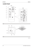
BRC7C62 / BRC7C67 (for FXC(Q))
1.1.1
Dimensions
2
1.1 BRC7C62 / BRC7C67
1.1
Unit (mm)
C: 3D007588A
1.1.2
Operation Manual
1-1
1
3
ON OFF
8
1-2
H
M
L
DOWN
10
C
6
ON OFF
UP
TEMP
H M L TIME
FAN
4
2
11
C
hr.
UP
9
hr.
FAN
DOWN
13
RESERVE CANCEL
hr.
5
TIMER
12
MODE
15
hr.
TEST
7
14
SWING
16
TEST
TEST
COOL/HEAT CHANGEOVER
REMOTE CONTROL SWITCH
18
20
17
21
19
24
23
22
25
3P107422-22S
Control Systems
13
Remote Controller (Wireless Type)
3
OH12-01
ON OFF
ON OFF
DOWN
3
C
UP
2 6
TEMP
TIME
C
UP
FAN
FAN
DOWN
4
RESERVE CANCEL
TIMER
1
MODE
SWING
/TEST
1
3
5
ON OFF
ON OFF
2 6
4-1
DOWN
C
UP
1
FAN
3
TEMP
TIME
C
UP
FAN
DOWN
RESERVE CANCEL
4
1
TIMER
MODE
1
4-2
SWING
5
/TEST
1
4-3
3P107422-22S
14
Control Systems
OH12-01
Remote Controller (Wireless Type)
2
ON OFF
24
TEMP
TIME
35
1
TEMP
TIME
UP
FAN
UP
1
DOWN
DOWN
FAN
RESERVE CANCEL
RESERVE CANCEL
TIMER
TIMER
MODE
SWING
1
2
MODE
SWING
3
4
/TEST
/TEST
ON OFF
2
ON ON
OFF OFF
TEMPTEMP
TIMETIME
TEMP
TIME
C
C
DOWN
24
6 TEMP
TIME
2
C
hr.
TIMER
hr.
FAN
3
(
4
TIMERTIMER
MODE
MODE
MODE
SWINGSWING
SWING
1
/TEST/TEST
24
6
UP
CODE
CANCEL
CANCEL
RESERVE
RESERVE
RESERVE CANCEL
/TEST
ON OFF
UP UP
DOWNDOWN
FAN FAN
UP
FAN
1.1 BRC7C62 / BRC7C67
ON OFF
)
UNIT NO.
DOWN
RESERVE CANCEL
TIMER
MODE
1
35
7
SWING
1
/TEST
1
3P107422-22S
Control Systems
15
Remote Controller (Wireless Type)
OH12-01
2. NAMES AND FUNCTIONS
OF THE OPERATING SECTION (Fig. 1, 2)
DISPLAY “
”
(SIGNAL TRANSMISSION)
1
This lights up when a signal is being
transmitted.
DISPLAY “
”“
”“
”“
”
“
” (OPERATION MODE)
2 This display shows the current OPERATION MODE. For straight cooling
type, “
” (Auto) and “
are not installed.
H
M
” (Heating)
C
DISPLAY “ hr.
”
hr.
(PROGRAMMED
TIME)
4
This display shows PROGRAMMED
TIME of the system start or stop.
5
DISPLAY “
” (AIR FLOW FLAP)
Refer to Note 1.
6
DISPLAY “
” “ ” (FAN SPEED)
The display shows the set fan speed.
8
9
10
12
13
14
15
L
DISPLAY “
”
3 (SET TEMPERATURE)
This display shows the set temperature.
7
11
TEST ” (INSPECTION/
DISPLAY “
TEST OPERATION)
When the INSPECTION/TEST OPERATION BUTTON is pressed, the display
shows the system mode is in.
ON/OFF BUTTON
Press the button and the system will
start. Press the button again and the
system will stop.
FAN SPEED CONTROL BUTTON
Press this button to select the fan
speed, HIGH or LOW, of your choice.
TEMPERATURE SETTING BUTTON
Use this button for SETTING TEMPERATURE (Operates with the front cover
of the remote controller closed.)
16
17
18
19
20
21
22
23
PROGRAMMING TIMER BUTTON
Use this button for programming
“START and/or STOP” time. (Operates
with the front cover of the remote controller opened.)
TIMER MODE START/STOP BUTTON
Refer to Note 2.
TIMER RESERVE/CANCEL BUTTON
Refer to Note 3.
AIR FLOW DIRECTION ADJUST BUTTON
Refer to Note 4.
OPERATION MODE SELECTOR BUTTON
Press this button to select OPERATION
MODE.
FILTER SIGN RESET BUTTON
Refer to the section of MAINTENANCE
in the operation manual attached to the
indoor unit.
INSPECTION/TEST OPERATION
BUTTON
This button is used only by qualified service
persons for maintenance purposes.
EMERGENCY OPERATION SWITCH
This switch is readily used if the remote
controller does not work.
RECEIVER
This receives the signals from the
remote controller.
OPERATING INDICATOR LAMP (Red)
This lamp stays lit while the air conditioner
runs. It flashes when the unit is in trouble.
TIMER INDICATOR LAMP (Green)
This lamp stays lit while the timer is set.
AIR FILTER CLEANING TIME
INDICATOR LAMP (Red)
Lights up when it is time to clean the air
filter.
DEFROST LAMP (Orange)
Lights up when the defrosting operation has started. (For straight cooling
type this lamp does not turn on.)
3P107422-22S
Note 1 : page 21, Note 2 : page 21, Note 3 : page 21, Note 4 : page 21
16
Control Systems
OH12-01
FAN/AIR CONDITIONING SELECTOR
SWITCH
Set the switch to “
” (FAN) for FAN
and “ ” (A/C) for HEAT or COOL.
COOL/HEAT CHANGEOVER SWITCH
25 Set the switch to “
COOL and “
” (COOL) for
” (HEAT) for HEAT.
NOTES
• For the sake of explanation, all indications are shown on the display in Figure 1
contrary to actual running situations.
• Fig. 1-2 shows the remote controller with
the front cover opened.
• Fig. 1-3 shows this remote controller can
be used in conjunction with the one provided with the VRV system.
• If the air filter cleaning time indicator lamp
lights up, clean the air filter as explained
in the operation manual provided with the
indoor unit.
After cleaning and reinstalling the air filter, press the filter sign reset button on
the remote controller. The air filter cleaning time indicator lamp on the receiver will
go out.
2
3. HANDLING FOR WIRELESS
REMOTE CONTROLLER
1.1 BRC7C62 / BRC7C67
24
Remote Controller (Wireless Type)
Precautions in handling remote controller
Direct the transmitting part of the remote
controller to the receiving part of the air
conditioner.
If something blocks the transmitting and receiving path of the indoor unit and the remote controller as curtains, it will not operate.
Receiver
2 short beeps
from the receiver
indicates that
the transmission
is properly done.
Transmitting distance is approximately 7 m.
Do not drop or get it wet.
It may be damaged.
Never press the button of the remote controller with a hard, pointed object.
The remote controller may be damaged.
Installation site
• It is possible that signals will not be received
in rooms that have electronic fluorescent
lighting. Please consult with the salesman
before buying new fluorescent lights.
• If the remote controller operated some
other electrical apparatus, move that
machine away or consult your dealer.
3P107422-22S
Control Systems
17
Remote Controller (Wireless Type)
OH12-01
Placing the remote controller in the
remote controller holder
Install the remote controller holder to a wall
or a pillar with the attached screw. (Make
sure it transmits)
Placing the
remote controller
Removing the
remote controller
Slide from above
Pull it upward
[CAUTIONS]
• Replace all batteries at the same time, do
not use new and old batteries intermixed.
• In case the remote controller is not used
for a long time, take out all batteries in
order to prevent liquid leak of the battery.
IN THE CASE OF CENTRALIZED CONTROL SYSTEM
If the indoor unit is under centralized control,
it is necessary to switch the remote controller’s setting.
In this case, contact your DAIKIN dealer.
4. OPERATION PROCEDURE
Remote
controller
holder
How to put the dry batteries
(1) Remove the back cover
of the remote controller
to the direction pointed
by the arrow mark.
(2) Put in batteries.
Use two dry cell batteries (AAA.LR03 (alkaline)). Put dry batteries
correctly to fit their (+)
and (–).
(3) Close the cover
When to change batteries
Under normal use, batteries last about a
year. However, change them whenever the
indoor unit doesn’t respond or responds
slowly to commands, or if the display
becomes dark.
• Operating procedure varies with heat
pump type and straight cooling type. Contact your Daikin dealer to confirm your system type.
• To protect the unit, turn on the main power
switch 6 hours before operation.
• If the main power supply is turned off during operation, operation will restart automatically after the power turns back on
again.
COOLING, HEATING, AUTOMATIC
AND FAN OPERATION (Fig. 3, 4)
• AUTOMATIC OPERATION can be
selected only by Heat recovery system.
• Cooling only system give selection of FAN
or COOLING OPERATION only.
〈〈FOR SYSTEMS WITHOUT COOL/
HEAT CHANGEOVER REMOTE CONTROL SWITCH (Fig. 3)〉〉
Press OPERATION MODE
1
SELECTOR button several
times and select the OPERATION
MODE of your choice as follows.
COOLING OPERATION.................. “
HEATING OPERATION ................... “
AUTOMATIC OPERATION .............. “
FAN OPERATION............................ “
”
”
”
”
3P107422-22S
18
Control Systems
OH12-01
Remote Controller (Wireless Type)
On AUTOMATIC OPERATION
[°C]
Setting
temperature
Press ON/OFF button.
2
〈〈FOR SYSTEMS WITH COOL/HEAT
CHANGEOVER REMOTE CONTROL
SWITCH (Fig. 4)〉〉
M
•
L
25
23
22
21
19
2
• The setting is impossible for fan operation.
4
Press FAN SPEED CONTROL
button.
High or Low fan speed can be selected.
Select OPERATION MODE with
the COOL/HEAT
CHANGEOVER REMOTE CONTROL
SWITCH as follows.
1
)
)
)
Press ON/OFF button.
2
•
Note:
OPERATION lamp lights up and the system
starts OPERATION.
COOING OPERATION ....................
Refer to fig. 4-1 ( ,
HEATING OPERATION ...................
Refer to fig. 4-2 ( ,
FAN OPERATION ............................
Refer to fig. 4-3 (
H
1.1 BRC7C62 / BRC7C67
In this operation mode, COOL/HEAT
changeover is automatically conducted at a
present indoor temperature.
OPERATION lamp lights up and the system
starts OPERATION.
5
Press AIR FLOW DIRECTION
button.
Refer to “ADJUSTING THE AIR FLOW
DIRECTION” (Note) for details.
STOPPING THE SYSTEM
Press ON/OFF button once
6
again.
OPERATION lamp goes off, and the system
stops OPERATION.
NOTE
• Do not turn OFF power immediately after
the unit stops. Then, wait no less than
5 minutes. Water is leaking or there is
something else wrong with the unit.
ADJUSTMENT
For programming TEMPERATURE and FAN
SPEED and AIR FLOW DIRECTION, follow
the procedure shown below.
[EXPLANATION OF HEATING
OPERATION]
DEFROST OPERATION
Press TEMPERATURE SETTING button and program the
setting temperature.
• As the frost on the coil of an outdoor unit
increase, heating effect decreases and the
system goes into DEFROST OPERATION.
• The fan operation stops and the
DEFROST lamp of the indoor unit goes on.
After 6 to 8 minutes (maximum 10 minutes) of DEFROST OPERATION, the system returns to HEATING OPERATION.
3
UP
DOWN
Each time this button is pressed,
setting temperature rises 1°C.
Each time this button is pressed,
setting temperature lowers 1°C.
In case of automatic operation
UP
DOWN
Each time this button is pressed, setting temperature shifts to “H” side.
Each time this button is pressed, setting temperature shifts to “L” side.
Heating capacity & Outdoor air temperature
• Heating capacity drops as outdoor air temperature lowers. If feeling cold, use
another heater at the same time as this air
conditioner.
3P107422-22S
Note : page 21
Control Systems
19
Remote Controller (Wireless Type)
• Hot air is circulated to warm the room. It
will take some time from when the air conditioner is first started until the entire room
becomes warm. The internal fan automatically turns at low speed until the air conditioner reaches a certain temperature on
the inside. In this situation, all you can do is
wait.
• If hot air accumulates on the ceiling and
feet are left feeling cold, it is recommended
to use a circulator. For details, contact the
place of purchase.
PROGRAM DRY OPERATION
(Fig. 5, 6)
• The function of this program is to decrease
the humidity in your room with the minimum temperature decrease.
• Micro computer automatically determines
TEMPERATURE and FAN SPEED.
• This system does not go into operation if
the room temperature is below 16°C.
〈〈FOR SYSTEMS WITHOUT COOL/
HEAT CHANGEOVER REMOTE CONTROL SWITCH (Fig. 5)〉〉
Press OPERATION MODE
SELECTOR button several
times and select “ ” (PROGRAM DRY
OPERATION).
1
2
Press ON/OFF button.
OPERATION lamp lights up and system
starts OPERATION.
ADJUSTMENT
3
OH12-01
NOTE
• Do not turn OFF power immediately after
the unit stops. Then, wait no less than
5 minutes. Water is leaking or there is
something else wrong with the unit.
〈〈FOR SYSTEMS WITH COOL/HEAT
CHANGEOVER REMOTE CONTROL
SWITCH (Fig. 6)〉〉
Select COOLING OPERATION
MODE with the COOL/HEAT
CHANGEOVER REMOTE CONTROL
SWITCH.
Press OPERATION MODE
2
SELECTOR button several
times and select PROGRAM DRY “ ”.
Press ON/OFF button.
3
1
OPERATION lamp lights up and the system
starts.
4
Press AIR FLOW DIRECTION
ADJUST button.
Refer to “ADJUSTING THE AIR FLOW
DIRECTION” (Note) for details.
STOPPING THE SYSTEM
Press ON/OFF button once
5
again.
OPERATION lamp goes off, and the system
stops OPERATION.
NOTE
• Do not turn OFF power immediately after
the unit stops. Then, wait no less than
5 minutes. Water is leaking or there is
something else wrong with the unit.
Press AIR FLOW DIRECTION
ADJUST button.
Refer to “ADJUSTING THE AIR FLOW
DIRECTION” (p. 9) for details.
STOPPING THE SYSTEM
Press ON/OFF button again.
4
OPERATION lamp goes off, and the system
stops OPERATION.
3P107422-22S
Note : page 21
20
Control Systems
OH12-01
Remote Controller (Wireless Type)
Press the AIR FLOW DIRECTION ADJUST
button to adjust up/down air flow angle.
Press the AIR FLOW DIRECTION ADJUST button to select
the air direction as shown below.
1
DISPLAY appears and the
air flow direction continuously varies. (Automatic
swing setting)
Press AIR FLOW DIRECTION ADJUST button to
select the air direction of
your choice.
DISPLAY vanishes and the
desired air flow direction is
fixed. (Fixed air flow setting)
• The movable limit of the blade is changeable. Contact your Daikin dealer for
details.
• The timer is operated by the following two
ways.
Programming the stop time (
)
....The system stops operating after the
time setting has elapsed.
Programming the start time (
)
.... The system starts operating after the
time setting has elapsed.
• The timer can be programmed for a maximum of 72 hours.
• The start and the stop time can simultaneously be programmed.
Press the TIMER MODE
START/STOP button several
times and select the mode on the display.
1
The display flashes.
For setting the timer stop...................“
For setting the timer start ..................“
Operation
conditions
Cooling
Heating
• When room
tempera• When room
ture is
temperahigher than
ture is lower
the set temthan the set
perature
temperature
• At defrost
operation
• When operating continuously at horizontal air flow
direction
”
”
Press the PROGRAMMING
TIMER button and set the time
for stopping or starting the system.
2
MOVEMENT OF THE AIR FLOW FLAP
For the following conditions, micro computer
controls the air flow direction so it may be different from the display.
Operation
mode
2
PROGRAM TIMER OPERATION
(Fig. 8)
1.1 BRC7C62 / BRC7C67
ADJUSTING THE AIR FLOW
DIRECTION (Fig. 7)
UP
DOWN
3
When this button is pressed, the
time advances by 1 hour.
When this button is pressed, the
time goes backward by 1 hour.
Press RESERVE button.
The timer setting procedure ends.
The display or changes from flashing light to
a constant light.
NOTE
• When setting the timer Off and On at the
same time, repeat the above procedure
from 1 to 3 once again.
Operation mode includes automatic operation.
3P107422-22S
Control Systems
21
Remote Controller (Wireless Type)
OH12-01
〈〈For Heat recovery system〉〉
For example.
ON OFF
TEMP
TIME
C
UP
FAN
DOWN
RESERVE CANCEL
hr.
TIMER
hr.
MODE
When the timer is
programmed to stop
the system after
3 hours and start the
system after
4 hours, the system
will stop after
3 hours and then
1 hour later the system will start.
• After the timer is programmed, the display
shows the remaining time.
• Press the TIMER OFF button to cancel
programming. The display vanishes. ( 4 )
HOW TO SET MASTER REMOTE
CONTROLLER (For VRV system)
• When the system is installed as shown
below, it is necessary to designate the
master remote controller.
〈〈For Heat pump system〉〉
When one outdoor unit is connected with
several indoor units.
Outdoor unit
Indoor unit
One of these remote controllers
needs to be designated as the
master remote controller.
When one BS unit is connected with several
indoor units.
Outdoor unit
BS unit
Indoor unit
One of these remote controllers
needs to be designated as the
master remote controller.
• Only the master remote controller can
select HEATING, COOLING or AUTOMATIC (only Heat recovery system)
OPERATION.
When the indoor unit with master remote
controller is set to “COOL”, you can switch
over operation mode between “FAN”, “DRY”
and “COOL”.
When the indoor unit with master remote
controller is set to “HEAT”, you can switch
over operation mode between “FAN” and
“HEAT”.
When the indoor unit with master remote
controller is set to “FAN”, you cannot switch
operation mode.
When attempting settings than that consented above, a “peep” is emitted as a warning.
Only with Heat recovery system, you can set
the indoor unit to AUTOMATIC. Attempting
to do so, a “peep” will be emitted as a warning.
3P107422-22S
22
Control Systems
OH12-01
Remote Controller (Wireless Type)
How to designate the master remote
controller
The displays showing “ ” of all slave indoor
unit connected to the same outdoor unit or
BS unit flash.
Press the OPERATION MODE
SELECTOR button to the
indoor unit that you wish to designate
as the master remote controller. Then
designation is completed. This indoor
unit is designated as the master
remote controller and the display
showing “ ” vanishes.
2
• To change settings, repeat steps
and 2 .
1
EMERGENCY OPERATION
When the remote controller does not work
due to battery failure or the absence thereof,
use this switch which is located beside the
discharge grille on the main unit. When the
remote controller does not work, but the battery low indicator on it is not lit, contact your
dealer.
[START]
1
Press the EMERGENCY
OPERATION switch.
The machine runs in the previous mode.
The system operates with the previously set
air flow rate.
1.1 BRC7C62 / BRC7C67
Continuously press the OPERATION MODE SELECTOR button for 4 seconds.
1
2
PRECAUTIONS FOR GROUP CONTROL SYSTEM OR TWO REMOTE
CONTROLLER CONTROL SYSTEM
This system provides two other control systems beside individual control (one remote
controller controls one indoor unit) system.
Confirm the following if your unit is of the following control system type.
Group control system
One remote controller controls up to 16
indoor units.
All indoor units are equally set.
Two remote controller control system
Two remote controllers control one indoor
unit. (In case of group control system, one
group of indoor units)
The unit follows individual operation.
NOTES
• Cannot have two remote controllers control system with only wireless remote controllers. (It will be a two remote controller
control system having one wired and one
wireless remote controllers.)
• Under two remote controller control system, wireless remote controller cannot
control timer operation.
• Only the operating indicator lamp out of 3
other lamps on the indoor unit display
functions.
NOTE
Contact your Daikin dealer in case of changing the combination or setting of group control and two remote controller control
systems.
[STOP]
2
Press the EMERGENCY OPERATION switch again.
3P107422-22S
Control Systems
23
Remote Controller (Wireless Type)
5. NOT MALFUNCTION OF
THE AIR CONDITIONER
OH12-01
Press the INSPECTION/TEST
button to select the inspection
mode “ ”.
1
The following symptoms do not indicate air conditioner malfunction
“ ” appears on display and blinks. “UNIT”
lights up.
I. THE SYSTEM DOES NOT OPERATE
• The system does not restart immediately
after the ON/OFF button is pressed.
If the OPERATION lamp lights, the system
is in normal condition. It does not restart
immediately because a safety device operates to prevent overload of the system.
After 3 minutes, the system will turn on
again automatically.
• The system does not restart immediately when TEMPERATURE SETTING
button is returned to the former position after pushing the button.
It does not restart immediately because a
safety device operates to prevent overload
of the system. After 3 minutes, the system
will turn on again automatically.
• If the reception beep is rapidly repeated
3 times (It sounds only twice when
operating normally.)
Control is set to the optional controller for
centralized control.
• If the defrost lamp on the indoor unit’s
display is lit when heating is started.
This indication is to warn against cold air
being blown from the unit. There is nothing
wrong with the equipment.
Press PROGRAMMING TIMER
BUTTON and change the unit
number.
2
Press to change the unit number until the
indoor unit beeps and perform the following
operation according to the number of beeps.
Number of beeps
3 short beeps .....Perform all steps from
to 6 .
1 short beep .......Perform 3 and 6
steps.
1 long beep ........Normal state
3
3
Press OPERATION MODE
SELECTOR BUTTON.
“ ” on the left-hand of the malfunction code
blinks.
Press PROGRAMMING TIMER
BUTTON and change the malfunction code.
4
Press until the indoor unit beeps twice.
5
Press OPERATION MODE
SELECTOR BUTTON.
“ ” on the right-hand of the malfunction
code blinks.
Press PROGRAMMING TIMER
BUTTON and change the malfunction code.
6
6. HOW TO DIAGNOSE TROUBLE SPOTS (Fig. 9)
I. EMERGENCY STOP
When the air conditioner stops in emergency,
the run lamp on the indoor unit starts blinking. Take the following steps yourself to read
the malfunction code that appears on the display. Contact your dealer with this code. It will
help pinpoint the cause of the trouble, speeding up the repair.
Press until the indoor unit makes a long
beep.
The malfunction code is fixed when the
indoor unit makes a long beep.
Reset of the display.
Press OPERATION MODE SELECTOR
BUTTON to get the display back to the normal state.
3P107422-22S
24
Control Systems
OH12-01
Remote Controller (Wireless Type)
[Trouble]
2
The RUN lamp of the indoor unit is flashing
and the unit does not work at all.
1.1 BRC7C62 / BRC7C67
II. IN CASE BESIDES EMERGENCY STOP
1. The unit does not operate at all.
• Check if the receiver is exposed of sunlight or strong light. Keep receiver away
from light.
• Check if there are batteries in the
remote controller. Place the batteries.
• Check if the indoor unit number and
wireless remote controller number are
equal.
Malfunction Code
Unit No. which
sensed trouble
ON OFF
TEMP
TIME
UP
CODE
FAN
Number
UNIT NO.
DOWN
RESERVE CANCEL
TIMER
MODE
SWING
/TEST
Operate the indoor unit with the remote controller of the same number.
Signal transmitted from a remote controller of
a different number cannot be accepted. (If
the number is not mentioned, it is considered
as “1”)
2. The system operates but it does not
sufficiently cool or heat.
• If the set temperature is not proper.
• If the FAN SPEED is set to LOW
SPEED.
• If the air flow angle is not proper.
Contact the place of purchase in the following case.
WARNING
When you detect a burning odor, shut
OFF power immediately and contact the
place of purchase. Using the equipment
in anything but proper working condition
can result in equipment damage, electric
shock and/or fire.
INSPECTION
display
[Remedial action]
Check the malfunction code (A1 ~ UF) on the
remote control and contact the place of purchase. (See Note)
Disposal requirements
Batteries supplied with the remote controller
are marked with this symbol.
This means that the batteries shall not be
mixed with unsorted household waste.
If a chemical symbol is printed beneath the
symbol, this chemical symbol means that the
battery contains a heavy metal above a certain concentration. Possible chemical symbols are:
Pb: lead (>0.004%)
Waste batteries must be treated at a specialized treatment facility for re-use.
By ensuring waste batteries are disposed of
correctly, you will help to prevent potential
negative consequences for the environment
and human health.
3P107422-22S
Note : page 24
Control Systems
25