1
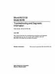
MicroVAX 3100 Models 88/98
User Information
Part Number: EK-MV489-UI. A01
November 1996
This book introduces the MicroVAX 3100 Model 88 and Model 98 systems. Use the
information in this book to configure, start, use, update, and troubleshoot your system.
You will also find general system information, such as console commands and system
care in this book.
Revision/Update Information:
Digital Equipment Corporation
Maynard, Massachusetts
This is a new manual.
First Printing, November 1996
Digital Equipment Corporation makes no representations that the use of its products in the manner described in this
publication will not infringe on existing or future patent rights, nor do the descriptions contained in this publication
imply the granting of licenses to make, use, or sell equipment or software in accordance with the description.
Possession, use, or copying of the software described in this publication is authorized only pursuant to a valid
written license from Digital or an authorized sublicensor.
© Digital Equipment Corporation 1996. All rights reserved.
The following are trademarks of Digital Equipment Corporation: MicroVAX, OpenVMS, ThinWire, VAX, and the
DIGITAL logo.
The following are third-party trademarks:
SIMM is a trademark of Molex Corporation.
All other trademarks and registered trademarks are the property of their respective holders.
[S3266]
Information - Class A
FCC NOTICE -- CLASS A DEVICE
Warning!
This is a Class A product. In a domestic environment this product may cause radio
interference in which case the user may be required to take adequate measures.
Achtung!
Dieses ist ein Gerät der Funkstörgrenzwertklasse A. In Wohnbereichen können bei Betrieb
dieses Gerätes Rundfunkstörungen auftreten, in welchen Fällen der Benutzer für
entsprechende Gegenmaßnahmen verantwortlich ist.
Avertissement!
Cet appareil est un appareil de Classe A. Dans un environnement résidentiel cet appareil
peut provoquer des brouillages radioélectriques. Dans ce cas, il peut être demandé à
l'utilisateur de prendre les mesures appropriées.
Table of Contents
1 System Overview
Introduction..........................................................................................................................1-1
System Unit..........................................................................................................................1-2
Enclosure Front Panel....................................................................................................1-4
Enclosure Rear Panel.....................................................................................................1-6
System Components ......................................................................................................1-8
System Board .............................................................................................................. 1-10
Internal Signal Cable Routing ...................................................................................... 1-12
Internal Power Cable Routing ...................................................................................... 1-14
The Keyboard .............................................................................................................. 1-16
2 Getting Started
Introduction ...................................................................................................................2-1
Before Starting Your System .........................................................................................2-2
Converting the System to Lie Flat on the Desktop .........................................................2-3
Locking Your System ....................................................................................................2-4
Identifying the Correct AC Power Cord .........................................................................2-6
Installing Your System ..................................................................................................2-7
Connecting System Components.............................................................................2-9
Connecting the Console Terminal ...........................................................................2-9
Network Connection and Termination................................................................... 2-10
Selecting ThinWire or ThickWire Ethernet ...........................................................2-11
Connecting ThinWire Ethernet ............................................................................. 2-12
Connecting ThickWire Ethernet............................................................................ 2-14
Connecting a SCSI Cable or the SCSI Terminator................................................. 2-15
Connecting External Options to the System .......................................................... 2-16
Connecting Peripherals to a DEC423 MMJ Port.................................................... 2-16
MicroVAX 3100 Models 88/98 User Information v
Table of Contents
Connecting a Peripheral to the Asynchronous Modem Control Port ...................... 2-17
Connecting Peripherals to an Optional Asynchronous Port.................................... 2-20
Connecting Peripherals to a DHW42-CB Option .................................................. 2-22
Connecting Peripherals to an Optional Synchronous Port...................................... 2-24
Installing a SCSI Terminator on an Optional KZDDA .......................................... 2-26
Connecting the Power Cord .................................................................................. 2-27
Starting Your System............................................................................................ 2-28
Checking the Power-Up Test Results .................................................................... 2-29
Testing the Ethernet Installation ........................................................................... 2-31
Completing the Ethernet Installation..................................................................... 2-32
If the Network Installation Fails............................................................................ 2-32
Removing the System Unit from a Network.......................................................... 2-32
Removing the System Unit from a ThinWire Ethernet Cable ................................ 2-33
Removing the System Unit from a ThickWire Ethernet Cable .............................. 2-33
Booting the Operating System .............................................................................. 2-34
Turning Off Your System ..................................................................................... 2-34
Computer Security....................................................................................................... 2-34
Posture and Work Habits ............................................................................................. 2-34
3 Installing Hardware Options
Introduction................................................................................................................... 3-1
Removing the Cover...................................................................................................... 3-2
Cache Memory .............................................................................................................. 3-3
System Memory ............................................................................................................ 3-3
Memory Configuration Rules.................................................................................. 3-3
Installing or Removing Memory Modules (SIMMs)....................................................... 3-4
Storage Devices.................................................................................................................... 3-6
General Information on Installing Drives....................................................................... 3-6
SCSI Addresses (SCSI ID’s) ................................................................................... 3-7
SCSI Termination ................................................................................................... 3-7
External SCSI Connector Termination.................................................................... 3-7
Internal SCSI Termination ...................................................................................... 3-8
SCSI Bus Length .................................................................................................... 3-8
Installing Optional Storage Devices...................................................................................... 3-8
Installing Devices in the Front Bay................................................................................ 3-8
Installing a Hard Disk Drive in the Rear Storage Bay .................................................. 3-12
Communications Options ................................................................................................... 3-14
Synchronous Communication Option........................................................................... 3-15
Installing the Synchronous Communication Option .............................................. 3-15
Asynchronous Communication Options ....................................................................... 3-16
Installing the Asynchronous Communication Option ............................................ 3-17
vi MicroVAX 3100 Models 88/98 User Information
Table of Contents
Optional SCSI Port (KZDDA) .....................................................................................3-18
Installing the KZDDA........................................................................................... 3-19
External Options................................................................................................................. 3-20
Connecting an External SCSI Option or Expansion Box ..............................................3-20
System Board Access .........................................................................................................3-22
4 Troubleshooting
Introduction ...................................................................................................................4-1
Initial Troubleshooting ..................................................................................................4-1
General Troubleshooting................................................................................................4-2
5 Diagnostic Tests and Commands
Power-Up Tests ............................................................................................................ 5–1
Diagnostic Tests and Utilities ....................................................................................... 5–4
Power-Up Error Messages............................................................................................. 5–9
Example 1.............................................................................................................. 5–9
Example 2............................................................................................................ 5–10
Example 3............................................................................................................ 5–11
Example 4............................................................................................................ 5–12
Example 5............................................................................................................ 5–13
Example 6............................................................................................................ 5–14
Configuration Display................................................................................................. 5–14
Error Display .............................................................................................................. 5–17
Contacting Digital Services ........................................................................................ 5–17
Equipment Log ........................................................................................................... 5–18
APPENDIX
A Console Commands
Entering Console Mode ........................................................................................................ A-1
Console Commands.............................................................................................................. A-1
BOOT............................................................................................................................ A-2
CONTINUE................................................................................................................... A-3
DEPOSIT ...................................................................................................................... A-4
EXAMINE..................................................................................................................... A-5
FIND ............................................................................................................................. A-6
HALT............................................................................................................................ A-7
MicroVAX 3100 Models 88/98 User Information vii
Table of Contents
APPENDIX (continued)
HELP ............................................................................................................................ A-7
INITIALIZE................................................................................................................ A-10
LOGIN ........................................................................................................................ A-11
MOVE......................................................................................................................... A-11
NEXT.......................................................................................................................... A-13
REPEAT ..................................................................................................................... A-15
SEARCH..................................................................................................................... A-16
SET ............................................................................................................................. A-18
SHOW......................................................................................................................... A-20
START........................................................................................................................ A-22
TEST........................................................................................................................... A-23
UNJAM....................................................................................................................... A-24
X -- Binary Load and Unload ...................................................................................... A-24
Controlling the Console Serial Line............................................................................. A-26
(Comment) .................................................................................................................. A-26
B Console Security
Console Security Feature...................................................................................................... B-1
Entering Console Mode ........................................................................................................ B-1
Setting the Security Password............................................................................................... B-1
Enabling the Console Security Feature .......................................................................... B-2
Logging in to Privileged Console Mode......................................................................... B-3
Changing the Security Password.................................................................................... B-4
Disabling the Console Security Feature ......................................................................... B-5
Exiting from Privileged Console Mode.......................................................................... B-5
C Setting the Defaults
Setting the Default Boot Device ........................................................................................... C-1
Setting the Default Recovery Action .................................................................................... C-2
viii MicroVAX 3100 Models 88/98 User Information
Table of Contents
APPENDIX (continued)
D System Care
Introduction.......................................................................................................................... D-1
Cleaning Your System Unit .................................................................................................. D-1
Cleaning Your Terminal ....................................................................................................... D-1
Cleaning Your Keyboard ...................................................................................................... D-2
Moving Your System............................................................................................................ D-2
Packing Your System ........................................................................................................... D-2
Installing Your System at a New Location............................................................................ D-3
E Technical Specifications
Introduction.......................................................................................................................... E-1
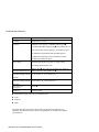
System Unit Specifications ................................................................................................... E-1
F Setting SCSI IDs
Selecting Available SCSI IDs on the System .........................................................................F-1
G Equipment Log
Introduction.......................................................................................................................... G-1
Equipment Log..................................................................................................................... G-1
MicroVAX 3100 Models 88/98 User Information ix
Table of Contents
LIST OF FIGURES
Figure 1-1 Front Controls, Indicators and Drive Bay Locations ............................................ 1-4
Figure 1-2 Rear Connectors (Rear View)............................................................................. 1-6
Figure 1-3 System Unit Components .................................................................................... 1-8
Figure 1-4 System Board Components................................................................................ 1-10
Figure 1-5 Internal SCSI Cable Routing ............................................................................. 1-12
Figure 1-6 Internal Power Cable Routing............................................................................ 1-14
Figure 1-7 Typical Keyboard Layout.................................................................................. 1-16
Figure 2-1 MicroVAX 3100 Model 88/98 System ................................................................ 2-2
Figure 2-2 Desktop Configuration ........................................................................................ 2-3
Figure 2-3 Removing the Front Door.................................................................................... 2-4
Figure 2-4 Removing the Cover............................................................................................ 2-5
Figure 2-5 Installing the Hasp............................................................................................... 2-6
Figure 2-6 System Enclosure Airflow................................................................................... 2-8
Figure 2-7 Connecting the Console Terminal ..................................................................... 2-10
Figure 2-8 Selecting the ThinWire or ThickWire Ethernet.................................................. 2-11
Figure 2-9 Assembling the ThinWire Ethernet Connector................................................... 2-12
Figure 2-10 Installing the ThinWire Ethernet ..................................................................... 2-13
Figure 2-11 Installing ThickWire Ethernet ......................................................................... 2-14
Figure 2-12 Connecting the SCSI Terminator..................................................................... 2-15
Figure 2-13 Connecting Peripherals to a DEC423 MMJ Port .............................................. 2-17
Figure 2-14 Connecting an EIA Connector to the Asynchronous Port................................. 2-18
Figure 2-15 Connecting a DEC423 Connector to the Asynchronous Port............................ 2-19
Figure 2-16 Connect a DHW42-BB Asynchronous Port...................................................... 2-21
Figure 2-17 Connecting to a DHW42-CB Asynchronous Port............................................. 2-23
Figure 2-18 Connecting to a DSW43-AA Synchronous Port ............................................... 2-25
Figure 2-19 Installing a SCSI Terminator on an Optional KZDDA..................................... 2-26
Figure 2-21 Turning the System On.................................................................................... 2-28
Figure 2-22 Recommendations for Posture and Work Habits.............................................. 2-35
Figure 3-1 Removing the Cover............................................................................................ 3-2
Figure 3-2 SIMM Bank Configuration.................................................................................. 3-4
Figure 3-3 Removing the SIMM Board ................................................................................ 3-5
Figure 3-4 Removing/Installing a SIMM Board.................................................................... 3-6
Figure 3-5 Installing the 3.5 Inch Brackets ........................................................................... 3-9
Figure 3-6 Removing the Front Bezel................................................................................. 3-10
Figure 3-7 Installing Optional Devices in the Front Bay ..................................................... 3-11
Figure 3-8 Removing the Rear Drive Bay........................................................................... 3-12
Figure 3-9 Installing Optional Hard Drives in the Rear Bay................................................ 3-13
Figure 3-10 Communication Slots ...................................................................................... 3-14
x MicroVAX 3100 Models 88/98 User Information
Table of Contents
LIST OF FIGURES (continued)
Figure 3-11
Figure 3-12
Figure 3-13
Figure 3-14
Figure 3-15
Installing the Synchronous Communication Option ......................................... 3-16
Installing the Asynchronous Communication Option .......................................3-18
Installing the KZDDA External SCSI Option................................................... 3-19
Removing System Board ................................................................................. 3-22
Removing the System Board Cover .................................................................3-23
MicroVAX 3100 Models 88/98 User Information xi
Table of Contents
LIST OF TABLES
Table 1-1 Front Controls, Indicators and Drive Bay Locations ............................................. 1-5
Table 1-2 Rear Connectors ................................................................................................... 1-7
Table 1-3 System Unit Components ..................................................................................... 1-9
Table 1-4 System Board Components................................................................................. 1-11
Table 1-5 Internal SCSI Cable Components ....................................................................... 1-13
Table 1-6 Internal Power Cable Components...................................................................... 1-15
Table 1-7 Key Groups and Functions.................................................................................. 1-17
Table 2-1 Recommendations for Posture and Work Habits ................................................. 2-35
Table 3-1 SCSI Address Recommendations.......................................................................... 3-7
Table 3-2 Communication Option Slot Locations ............................................................... 3-15
Table 3-3 Interface Standards and Cable Part Numbers ...................................................... 3-15
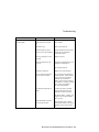
Table 4-1 System Troubleshooting ....................................................................................... 4-2
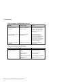
Table 4-1 System Troubleshooting (continued) .................................................................... 4-4
Table 4-2 Disk Drive Troubleshooting.................................................................................. 4-4
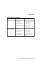
Table 4-3 Terminal Troubleshooting .................................................................................... 4-5
Table 5-1 Option Card Tests................................................................................................ 5–7
Table C-1 Alternative Boot Devices .................................................................................... C-1
Table C-2 Default Recovery Actions and Associated Values ............................................... C-2
Table E-1 System Specifications ..........................................................................................E-1
Table E-2 Acoustic Levels ...................................................................................................E-3
Table E-3 System Unit Metrics.............................................................................................E-3
Table E-4 System Operating and Nonoperating Conditions ..................................................E-3
Table E-5 AC Power Cords (Country Specific)....................................................................E-4
Table F-1 Devices and Priorities Normally Associated with SCSI IDs..................................F-2
Table G-1 Hardware Components........................................................................................ G-2
Table G-2 SCSI Addresses .................................................................................................. G-3
Table G-3 Hardware Configuration ..................................................................................... G-3
Table G-4 Installed Software............................................................................................... G-3
xii MicroVAX 3100 Models 88/98 User Information
Preface
Welcome to the MicroVAX 3100 Model 88 and Model 98
Systems
This book introduces the MicroVAX 3100 Model 88 and Model 98 Systems.
Use the information in this book to configure, start, use, update, and troubleshoot your
MicroVAX 3100 Model 88 and Model 98 Systems. You can also find general system
information such as console commands and system care in this book.
Audience
If you will be operating, configuring, or adding options to the MicroVAX 3100 Model 88
and Model 98 Systems, the information included in this book will be helpful to you.
Organization of the Information
This information for users covers the following topics:
•
Chapter 1, System Overview, describes the hardware components, including the Small
Computer Systems Interface (SCSI) architecture, the controller, the keyboard, the
system unit front panel, and the system unit rear panel.
•
Chapter 2, Getting Started, describes installing, starting, restarting, and turning off the
system.
•
Chapter 3, Installing Hardware Options, describes the system unit components and
gives instructions and illustrations to help you remove and replace them.
•
Chapter 4, Troubleshooting, describes system troubleshooting.
•
Chapter 5, Diagnostic Tests and Commands, describes system troubleshooting.
•
Appendix A, Console Commands, contains a basic description of the console
commands.
MicroVax 3100 Models 88/98 User Information xiii
Preface
•
Appendix B, Console Security, Provides information on setting the security password,
and logging in to the privileged console mode.
•
Appendix E, System Defaults, describes how to set/change the default boot device and
how to set/change the default recovery action.
•
Appendix D, System Care, describes how to clean your system, terminal, and
keyboard. It also contains instructions for moving and reinstalling your system.
•
Appendix E, Technical Specifications, describes the technical characteristics of the
system.
•
Appendix F, Setting SCSI IDs, describes how to select a unique SCSI ID for any SCSI
device installed in or attached to your system.
•
Appendix G, Equipment Log, contains tables that you can use to record information
about your system hardware and software components.
Refer to the Table of Contents for a detailed listing of topics.
Conventions
This guide uses the following conventions:
Convention Example
PARAMS>SHOW NODENAME>
Description
Monospaced, bold text indicates file names, path
names, directories, or screen text.
[Enter]
Square brackets surrounding text represent a key on
the keyboard.
[Ctrl]+[R]
A plus sign between keyboard keys indicates that
the keys shown should be pressed at the same time.
auto_action
Italic text indicates environment variables. Titles of
information sources are in italic, and occasionally
italic is used for emphasis in the text.
)
A pointing hand indicates a reference to additional
information.
xiv MicroVAX 3100 Models 88/98 User Information
Preface
Abbreviations
This guide uses the following abbreviations:
Abbreviation
Meaning
AC
alternating current
amp
ampere
C
Celsius
CD
compact disc
CD-ROM
compact disc read-only memory
CEE
International Commission for Conformity Certification of
Electrical Equipment
CFG
configuration file
cm
centimeters
CPU
central processing unit
CSA
Canadian Standards Association
DC
direct current
DMA
direct memory access
DRAM
dynamic random-access memory
FDI
Floppy Drive Interconnect
flashROM
electrically erasable, rewriteable, nonvolatile memory
ft
feet
GB
gigabyte
Hz
hertz
IEC
International Electrotechnical Commission
I/O
input/output
IRQ
interrupt request
ISO
International Organization for Standardization
Kb
kilobit
KB
kilobyte
kg
kilogram
lb
pound
LED
light-emitting diode
m
meter
MicroVAX 3100 Models 88/98 User Information xv
Preface
Abbreviation
Meaning
MAU
media adapter unit
Mb
megabit
MB
megabyte
MHz
megahertz.
mm
millimeter
ns
nanoseconds
NVRAM
nonvolatile random-access memory
ROM
read-only memory
SCSI
small computer system interface
SIMMs
single in-line memory modules
SROM
serial read-only memory
UL
Underwriters Laboratories
VAR
value-added reseller
V AC
volts alternating current
VMS
Open VMS Operating System
W
watt
xvi MicroVAX 3100 Models 88/98 User Information
Preface
Special Notices
This guide uses three kinds of notices to emphasize specific information.
________________________WARNING __________________________
A WARNING indicates the presence of a hazard that can cause personal
injury.
____________________________________________________________
________________________ CAUTION ___________________________
A CAUTION indicates the presence of a hazard that can cause damage to
hardware or that might corrupt software.
____________________________________________________________
__________________________NOTE ____________________________
A NOTE gives general information, such as compatibility with other products or
pointers to other information.
____________________________________________________________
Additional Information Resources
You may wish to consult the following information resource for additional information
about your MicroVAX 3100 Model 88/98 System:
•
MicroVAX 3100 Models 88/98 Installation Information (order number EK-MV489-II),
which presents a graphical overview of the system installation.
Contact your distributor or Digital representative for other available product-related
information.
MicroVAX 3100 Models 88/98 User Information xvii
Preface
Reader’s Comments
Digital welcomes your comments on this or any other manual.
Digital Equipment Corporation
Shared Engineering Services
PKO3-2/21J
129 Parker Street
Maynard, MA 01754-2199
Please reference order number EK-MV489-UI. A01 in your correspondence.
xviii MicroVAX 3100 Models 88/98 User Information
1
System Overview
Introduction
Congratulations on your purchase of a MicroVAX 3100 Model 88/98 System. This
machine has been designed and tested with the utmost attention to performance and
reliability. Your system runs the OpenVMS operating system; its performance range can
be extended by the addition of memory and hard disk drives.
This chapter describes the MicroVAX 3100 Model 88/98 System’s hardware components,
including the Small Computer Systems Interface (SCSI) architecture, the keyboard, the
system unit front panel, and the system unit rear panel.
Following the information provided here will assure safe and proper operation of your
MicroVAX 3100 Model 88/98 System.
MicroVax 3100 Models 88/98 User Information 1-1
System Overview
System Unit
Your MicroVAX 3100 Model 88/98 System uses a mini-tower desktop enclosure.
The system unit includes:
•
CPU module/motherboard with built-in SCSI, NI Bus and port, Console port, and 2
serial ports, as well as:
•
Model 88
16 ns NVAX CPU chip
128 KB of on-board cache memory
•
From 64 MB to 512 MB of memory, consisting of single in-line memory modules
(SIMMs)
•
Six accessible/non-accessible drive bays
Model 98
10 ns NVAX CPU chip
512 KB of on-board cache memory
a) One with a standard 5.25-inch CD-ROM drive
b) One with a standard 3.5-inch RZ26 SCSI disk
c) Two more slots for optional 3.5 or 5.25-inch hard disk or removable-media drives
d) Two non-accessible I/O bays (for optional 3.5 inch hard disk drives only).
1-2 MicroVAX 3100 Models 88/98 User Information
System Overview
•
Two SCSI ports; one standard and one optional
•
Synchronous and asynchronous communication adapters (optional).
•
ThinWire and ThickWire Ethernet
•
3-year, on-site warranty
•
OpenVMS 5.5-2XX
)
Refer to Appendix E, Technical Specifications, for additional information.
MicroVAX 3100 Models 88/98 User Information 1-3
System Overview
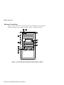
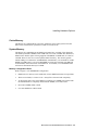
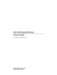
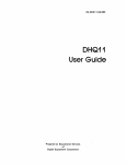
Enclosure Front Panel
Figure 1-1 shows a front view of the system enclosure with pointers to the controls and
indicators (storage bay door opened for clarity). Table 1-1 describes these items.
2
4
5
3
6
1
7
8
9
10
11
12
MLO-013510
Figure 1-1 Front Controls, Indicators and Drive Bay Locations
1-4 MicroVAX 3100 Models 88/98 User Information
System Overview
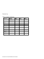
Table 1-1 Front Controls, Indicators and Drive Bay Locations
Figure
Legend
Component
1
Front door
2
Power switch
3
Disk drive LED
4
Power LED
5
Halt switch: halts the system and returns it from the operating
system to the console mode.
6
RZ 2x SCSI disk (non-accessible)
7
Accessible/Nonaccessible bay for 3.5-inch or 5.25-inch
8
Accessible/Nonaccessible bay for 3.5-inch or 5.25-inch
9
CD-ROM volume switch
10
CD-ROM headphone jack
11
CD-ROM activity light
12
CD-ROM eject button
MicroVAX 3100 Models 88/98 User Information 1-5
System Overview
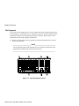
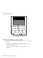
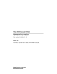
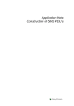
Enclosure Rear Panel
Table 1-2 show the controls and connectors. Table 1-2 lists the rear controls and
connectors and describes their functions.
7
8
9
1
10
2
11
3
12
4
13
5
14
15
16
17
6
18
19
MLO-013511
Figure 1-2 Rear Connectors (Rear View)
1-6 MicroVAX 3100 Models 88/98 User Information
System Overview
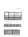
Table 1-2 Rear Connectors
Figure
Legend
Component
1
SCSI Port (terminator required)
2
2A AC Power Outlet Connection
3
AC Power Input Connector
4
Pre-installed Software Label
5
System Identification Label
6
Lockdown Hasp
7
ThinWire Ethernet
8
ThinWire Ethernet LED
9
ThickWire Ethernet
10
ThickWire Ethernet LED
11
Modem Port (with adapter)
12
MMJ Port (for Console only)
13
MMJ Port
14
MMJ Port
15
Asynchronous Communication (optional)
16
Synchronous Communication (optional)
17
Reserved
18
Reserved
19
KZDDA SCSI Port (optional)
MicroVAX 3100 Models 88/98 User Information 1-7
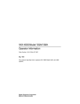
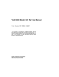
System Overview
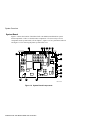
System Components
Figure 1-3 shows the location of the MicroVAX 3100 Model 88 and Model 98 Systems
components. Table 1-3 lists the system components.
4
1
5
6
3
7
8
2
12
11
10
9
MLO-013606
Figure 1-3 System Unit Components
1-8 MicroVAX 3100 Models 88/98 User Information
System Overview
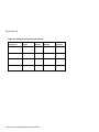
Table 1-3 System Unit Components
Figure
Legend
Component
1
Front Door
2
CD-ROM
3
System Disk Drive
4
System Board
5
SIMM Board (required)
6
SIMM Board (optional)
7
Power Supply
8
Rear Drive Bay
9
DHW42 Asynchronous Option
10
DSW43 Synchronous Option
11
SCSI (2nd) Optional
12
CDAL I/O Board
MicroVAX 3100 Models 88/98 User Information 1-9
System Overview
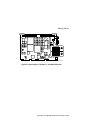
System Board
Figure 1-4 shows the location of the MicroVAX 3100 Model 88 and Model 98 system
board components. Table 1-4 describes these components. If it is necessary to access
components on the system board, refer to Chapter 3, Figure 3-14 for system board removal
and Figure 3-15 for removing the plastic system board cover.
2
3
4
5
6
7
1
8
9
10
11
12
13
16
15
14
MLO-013516
Figure 1-4 System Board Components
1-10 MicroVAX 3100 Models 88/98 User Information
System Overview
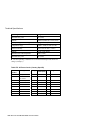
Table 1-4 System Board Components
Figure
Legend
Components
1
CPU Fan Connector (J25)
2
MEM1 Carrier Connector (J4)
3
MEM2 Carrier Connector (J1)
4
Diagnostic Display LEDs (D26, D29); indicate system and test status
for Digital Services engineers using the on-line Service Guide.
5
Diagnostic Display LEDs (D31)
6
Break/Enable Switch (See
below)
7
Thick/ThinWire Ethernet Jumper (J27) ThinWire Default
8
ThinWire Ethernet Connection (J24)
9
ThickWire Ethernet Connection (J21)
10
Modem Connector (J11)
11
Console Port MMJ (J9)
12
Console Port MMJ (J8)
13
Console Port MMJ (J2)
14
NVAX CPU (E36)
15
19.2/38.4 K baud Jumper (W13) 19.2k baud default
16
19.8 K baud Jumper (J26) Default Installed
Break/Enable Switch Positions
a)
When the switch is in the up position, the LED is on and you can halt the
system by pressing the break key on the console terminal keyboard.
b) When the switch is in the down position, the LED is off and you can not halt
the system by pressing the break key on the console terminal keyboard.
MicroVAX 3100 Models 88/98 User Information 1-11
System Overview
Internal Signal Cable Routing
Figure 1-5 shows the routing of the SCSI cable in MicroVAX 3100 Models 88/98 systems.
Table 1-5 lists the components.
8
7
6
5
3
2
4
1
MLO-013704
Figure 1-5 Internal SCSI Cable Routing
1-12 MicroVAX 3100 Models 88/98 User Information
System Overview
Table 1-5 Internal SCSI Cable Components
Figure
Legend
Components
1
CDAL I/O
2
Optional Hard Drive
3
Optional Hard Drive
4
CD-ROM
5
Optional Storage Device
6
Optional Storage Device
7
Hard Drive
8
Terminated SCSI Port
MicroVAX 3100 Models 88/98 User Information 1-13
System Overview
Internal Power Cable Routing
Figure 1-6 shows the routing of the internal power cable in MicroVAX 3100 Models 88/98
systems. Table 1-6 lists the components.
1
8
7
6
2
3
5
4
MLO-013703
Figure 1-6 Internal Power Cable Routing
1-14 MicroVAX 3100 Models 88/98 User Information
System Overview
Table 1-6 Internal Power Cable Components
Figure
Legend
Components
1
Power Supply
2
Optional Hard Drive
3
Optional Hard Drive
4
CDAL I/O
5
CD-ROM
6
Optional Storage Device
7
Optional Storage Device
8
Hard Drive
MicroVAX 3100 Models 88/98 User Information 1-15
System Overview
The Keyboard
Your system comes equipped with a 101-key enhanced keyboard (ordered separately and
shown in Figure 1-7) that allows you to communicate with your system by entering data or
commands. Note that some European keyboards have 108 keys. Refer to Table 1-7 for
information on keyboard key groups and functions.
)
Refer to your operating system or application software documentation for softwarespecific key functions.
_________________________ NOTE____________________________
You can adjust the angle of the keyboard for your comfort. The underside of the
keyboard has feet that swing down and lock into place.
___________________________________________________________
Figure 1-7 Typical Keyboard Layout
1-16 MicroVAX 3100 Models 88/98 User Information
System Overview
Table 1-7 Key Groups and Functions
Figure
Legend
Key, Key Group
Function
1
[Escape] key
This key is program-specific. Its function is
determined by the installed application
software.
2
Function key group
These keys are program-specific. Their
functions are determined by the installed
application software.
3
Edit key group
These keys are program-specific. Their
functions are determined by the installed
application software.
4
Indicator lights
These lights indicate whether [NumLock],
[CapsLock], or [ScrollLock] has been
activated.
5
Numeric keypad
These keys perform numeric functions and
software-defined functions, including cursor
control. The [NumLock] key allows you to
toggle between the numeric functions and
software-defined functions.
6
Cursor control key group
These keys control the movement of the
highlighted cursor on the terminal screen.
7
Alphanumeric key group
These typewriter-specific keys feature
automatic-repeat capability. If you press and
hold down any of these keys, the keystroke
repeats automatically until released.
MicroVAX 3100 Models 88/98 User Information 1-17
2
Getting Started
Introduction
This chapter describes how to install, start, restart, and turn off your MicroVAX 3100
Model 88 and Model 98 Systems. You can also find information here about preloaded
software as well as guidelines for system security. Figure 2-1 shows a typical MicroVAX
3100 Model 88 and Model 98 System in its tower configuration.
________________________WARNING __________________________
When unpacking and moving system components, be aware that some
components (such as the system unit or terminal) may be too heavy for you
to safely lift alone. If you are doubtful about whether you can lift these items
alone, please get assistance.
____________________________________________________________
MicroVax 3100 Models 88/98 User Information 2-1
Getting Started
ML013512
Figure 2-1 MicroVAX 3100 Model 88/98 System
Before Starting Your System
Before you start your system MicroVAX 3100 Model 88 and Model 98 System, follow this
procedure:
1.
Read and understand the information supplied with your system.
2.
Select a well-ventilated site near a grounded power outlet and away from sources of
excessive heat. Also, use an appropriate power strip to isolate the site from electric
noise (for example, spikes, sags, and surges) produced by devices such as air
conditioners, large fans, radios, and televisions.
3.
Save all shipping containers and packing material for repackaging or moving the
system later.
_________________________ NOTES ___________________________
•
Do not install optional hardware or application software until you have
started your system and verified that the base system is working correctly.
•
On systems that have preloaded software, a label attached to the system unit
informs you that there is licensed software installed. Carefully review the
software license agreement shipped with your system.
___________________________________________________________
2-2 MicroVAX 3100 Models 88/98 User Information
Getting Started
Converting the System to Lie Flat on the Desktop
Your MicroVAX 3100 Model 88 or Model 98 system is shipped in the tower configuration
as shown in Figure 2-1. The system can also be used in a desktop configuration as shown
in Figure 2-2.
MLO-013649
Figure 2-2 Desktop Configuration
_________________________ Caution ___________________________
If you will be using the system in the horizontal desktop position as shown, you
must use clips that will prevent the CD-ROM media from falling out of the tray
when ejected. Please refer to the User Guide that is supplied with the CD drive
for instructions on using the clips.
____________________________________________________________
MicroVAX 3100 Models 88/98 User Information 2-3
Getting Started
If you wish to use your MicroVAX 3100 Model 88/98 system in its desktop configuration,
you must first remove the front door.
1.
With the door open, push on each hinge, as shown, to disengage them. Lift the door
away. See Figure 2-3.
MLO-013607
Figure 2-3 Removing the Front Door
2.
Set the system down with the power button on the bottom left as shown in Figure 2-2.
3.
Place the front door in a secure location. You may wish to use the system in its tower
configuration at some other time.
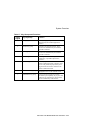
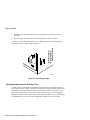
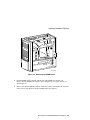
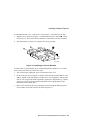
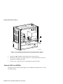
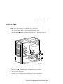
Locking Your System
Your MicroVAX 3100 Model 88 or Model 98 system may be locked and/or secured to a
desk or table using a lockdown hasp. Follow these instructions and see Figure 2-4 to
expose and install the hasp.
2-4 MicroVAX 3100 Models 88/98 User Information
Getting Started
_________________________ Caution ___________________________
a.
To avoid damage from static discharge, touch bare (unpainted) metal on the
system box before you touch anything inside the system.
b. To avoid damage from overheating, system covers must be in place when
running the system for extended periods of time.
____________________________________________________________
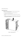
1.
2.
Make sure the system is turned off and unplugged.
Facing the rear of the unit, locate and loosen the three thumbscrews that fasten the
top cover to the enclosure. Pull back on the cover (two or three inches), and lift the
cover up and away from the enclosure.
1
MLO-013628
Figure 2-4 Removing the Cover
MicroVAX 3100 Models 88/98 User Information 2-5
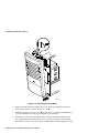
Getting Started
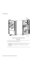
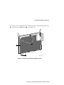
3.
Insert the end of the hasp with the hole in it through the slot on the rear of the
enclosure.
4.
Place the other end of the hasp securely behind the slot on the rear panel.
You may use a lock through the hasp, or use a chain or cable lock through the hasp to
secure the system to a table. Refer to Figure 2-5.
ML013514
Figure 2-5 Installing the Hasp
Identifying the Correct AC Power Cord
Your MicroVAX 3100 Model 88 and Model 98 System comes equipped the proper AC
power cord. However, because variations exist from one country to another, MicroVAX
3100 Model 88 and Model 98 and systems may be moved, inspect your power cord to
ensure that it is the correct one for your country or region. If you are not sure that the
supplied AC power cord is correct, contact your authorized Digital service representative
or distributor before you use it. Refer to Appendix E, Table E-5, for list of cables.
2-6 MicroVAX 3100 Models 88/98 User Information
Getting Started
________________________WARNING __________________________
Do not attempt to modify or use an external 115V AC power cord for 230V
AC input power. Modifying the power cord can cause personal injury and
severe equipment damage.
____________________________________________________________
Power cords supplied with the MicroVAX 3100 Model 88 and Model 98 System meet the
following criteria:
•
The cords set for North America are UL-listed/CSA-certified, and rated 120VAC, 10A
minimum.
•
In Europe, the cordage carries the <HAR> mark. See Table E-5, Appendix E for
ratings.
•
The cordage is terminated in a grounding-type plug and must have approvals showing
it is suitable for use within the region.
•
The connector at the equipment end must be an IEC3201-type CEE2 style 14
connector.
•
The cord length does not exceed 4.5 m (14.5 ft).
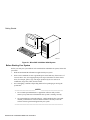
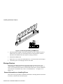
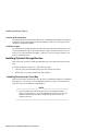
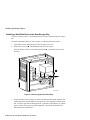
Installing Your System
The MicroVAX 3100 Model 88 and Model 98 System Installation Information you received
with your system graphically outlines the steps to follow to install your system.
1.
Make sure you received all of your system components. Use Appendix G, Equipment
Log, to list your equipment. If something is missing, please contact your distributor or
Digital representative.
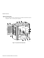
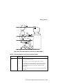
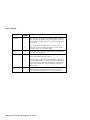
2.
Position your system so that air can flow freely to and from the vents. Figure 2-6
shows the airflow from the front and rear of the system.
1
International Electrotechnical Commission.
2
International Commission for Conformity Certification of Electrical Equipment.
MicroVAX 3100 Models 88/98 User Information 2-7
Getting Started
MLO-013695
Figure 2-6 System Enclosure Airflow
_______________________ CAUTIONS _________________________
To ensure that your system is properly cooled:
•
Make sure that air can freely flow into the front, and out of the rear of the
system unit.
• Do not remove a filler plate until you are ready to add a new system
component.
___________________________________________________________
2-8 MicroVAX 3100 Models 88/98 User Information
Getting Started
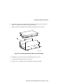
Connecting System Components
To connect the components of your MicroVAX 3100 Model 88 and Model 98 System,
follow this procedure:
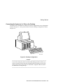
Connecting the Console Terminal
To connect the console terminal, refer to Figure 2-7 and follow these steps:
1.
Connect one end of the terminal cable to the modified modular jack (MMJ) port on
the rear of the system.
2.
Connect the other end of the cable to the MMJ port on the console terminal itself.
3.
Connect the terminal power cord to the terminal and an isolated, grounded circuit.
See the terminal documentation for more information.
MLO-013616
Figure 2-7 Connecting the Console Terminal
MicroVAX 3100 Models 88/98 User Information 2-9
Getting Started
_________________________ NOTE____________________________
When the system is shipped, MMJ ports 0 and 1 are covered with an arrow
label identifying port 3 as the console port. When port 3 has been identified,
the OPA0 arrow label may be removed.
___________________________________________________________
Network Connection and Termination
Your MicroVAX 3100 Model 88/98 System can be connected to either a ThinWire
Ethernet or a ThickWire Ethernet network. A jumper on the system board determines
whether you are using ThinWire or ThickWire Ethernet.
If you do not use an Ethernet network, you should install the ThinWire and ThickWire
terminators on the back of your system as shown in Figure 2-12 and Figure 2-19
respectively.
If you will be using either ThinWire or ThickWire Ethernet, follow these general steps,
which are detailed in the following sections.
1.
Select ThinWire or ThickWire by installing the jumper on the system board.
2.
Assemble/connect the network to the appropriate port.
3.
Test the network connection.
4.
Notify the network coordinator to complete the installation.
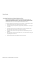
Selecting ThinWire or ThickWire Ethernet
Select either ThinWire Ethernet or ThickWire Ethernet by installing the selector jumper
on the system board module. Install the jumper in the setting position for ThinWire
Ethernet, and in the setting position for ThickWire Ethernet (See Figure 2-8).
2-10 MicroVAX 3100 Models 88/98 User Information
Getting Started
1
2
MLO-013614
Figure 2-8 Selecting the ThinWire or ThickWire Ethernet
MicroVAX 3100 Models 88/98 User Information 2-11
Getting Started
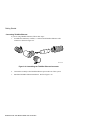
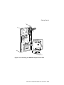
Connecting ThinWire Ethernet
If you are using ThinWire Ethernet, follow these steps:
1.
Assemble the terminator, extender, t-connector and ThinWire Ethernet Cable
connector as shown in Figure 2-9.
MLO-013701
Figure 2-9 Assembling the ThinWire Ethernet Connector
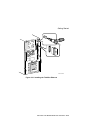
2.
Connect the assembly to the ThinWire Ethernet port on the rear of the system.
3.
Install the ThickWire Ethernet terminator. Refer to Figure 2-10.
2-12 MicroVAX 3100 Models 88/98 User Information
Getting Started
MLO-013615
Figure 2-10 Installing the ThinWire Ethernet
MicroVAX 3100 Models 88/98 User Information 2-13
Getting Started
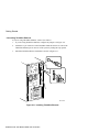
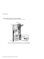
Connecting ThickWire Ethernet
If you are using ThickWire Ethernet, connect it as follows:
1.
If you are using ThickWire Ethernet, configure the jumper as in Figure 2-8.
2.
Attach the 15-pin connector on the ThickWire Ethernet transceiver cable to the
ThickWire Ethernet port on the rear of the system by sliding the clip upward.
3.
Install the ThinWire Ethernet terminator as shown in Figure 2-11.
MLO-013616
Figure 2-11 Installing ThickWire Ethernet
2-14 MicroVAX 3100 Models 88/98 User Information
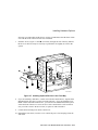
Getting Started
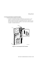
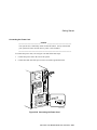
Connecting a SCSI Cable or the SCSI Terminator
To connect the SCSI terminator, follow these steps:
1.
If you have an external small computer system interface (SCSI) interface or SCSI
storage box, connect the SCSI cable to the SCSI port on the rear of the system,
otherwise install the SCSI terminator (supplied with your system). Figure 2-12 shows
an example of the SCSI terminator connection. See the section on SCSI Termination
in Chapter 3 for additional information.
MLO-013623
Figure 2-12 Connecting the SCSI Terminator
MicroVAX 3100 Models 88/98 User Information 2-15
Getting Started
Connecting External Options to the System
The following subsections contain information on these tasks:
•
Connecting peripherals to a DEC423 MMJ port
•
Connecting a peripheral to the asynchronous modem control port (port2)
•
Connecting peripherals to an optional asynchronous port
•
Connecting peripherals to an optional synchronous port
Connecting Peripherals to a DEC423 MMJ Port
To connect peripherals that use DEC423 cables (BC16E) to MMJ ports 0, 1,
or 3, refer to Figure 2-13 follow these steps:
1.
Set the on/off switch on the peripheral to the off (O) position.
2.
Verify the MicroVAX is Off and Power Cord is removed.
3.
Connect one end of the DEC423 cable to either MMJ port 0, 1, or 3
4.
Connect the other end of the DEC423 cable to the correct port on the peripheral.
5.
Set the on/off switch on the peripheral to the on position.
BC16E cables are available in the following lengths:
10 feet (BC16E-10), 25 feet (BC16E-25), or 50 feet (BC16E-50).
2-16 MicroVAX 3100 Models 88/98 User Information
Getting Started
MLO-013617
Figure 2-13 Connecting Peripherals to a DEC423 MMJ Port
Connecting a Peripheral to the Asynchronous Modem Control Port
You can connect peripherals that use EIA-232 connectors to the asynchronous modem
control port on the back of the system unit. Alternatively, the supplied EIA-232 to
DEC423 adapter (H8575-A) allows you to connect peripherals that use DEC423
connectors. This port may be used as a terminal port as well as a modem port.
If you are connecting a peripheral to the asynchronous modem control port using EIA-232
cables, refer to Figure 2-14 and follow these steps:
a)
Set the ON/OFF switch on the peripheral to the OFF (O) position.
b) Connect the 25-pin D-sub connector of the peripheral cable to the asynchronous
modem control port.
c)
If the connector has screws on either side, tighten them using a small screwdriver.
d) Connect the other end of the peripheral cable to the correct port on the peripheral.
e)
Set the ON/OFF switch on the peripheral to the ON position.
MicroVAX 3100 Models 88/98 User Information 2-17
Getting Started
EIA-232 cables are available in the following lengths: 10 feet (BC22F-10), 25 feet
(BC22F-25), or 50 feet (BC22F-50). The peripheral you are using may require a nullmodem extension cable. See the peripheral documentation or contact your Digital sales
representative for information on the correct null-modem cable to use.
________________________ Caution ___________________________
This modem control port has default support for non-standard 19.8 Kbaud. To
change to 19.2 Kbaud, user must remove Jumper on J26 on the CPU mother
board. Refer to Chapter 3, Figure 3-14.
___________________________________________________________
MLO-013618
Figure 2-14 Connecting an EIA Connector to the Asynchronous Port
2-18 MicroVAX 3100 Models 88/98 User Information
Getting Started
If you are connecting a peripheral using DEC423 cables, refer to Figure 2-15 and follow
these steps: Set the ON/OFF switch on the peripheral to the OFF (O) position.
a)
Connect the EIA-232 to DEC423 adapter to the asynchronous modem control port.
b) Tighten the screws on each side of the adapter using a small screwdriver.
c)
Connect the DEC423 cable to the MMJ port on the adapter.
d) Connect the other end of the DEC423 cable to the correct port on the peripheral.
e)
Set the ON/OFF switch on the peripheral to the ON (l) position.
MLO-013619
Figure 2-15 Connecting a DEC423 Connector to the Asynchronous Port
MicroVAX 3100 Models 88/98 User Information 2-19
Getting Started
Connecting Peripherals to an Optional Asynchronous Port
There are two asynchronous communications options for Micro VAX 3100 88/98 systems:
•
DHW42-BB -- Provides two eight-line data-line-only asynchronous ports
•
DHW42-CB -- Provides two four-line asynchronous ports with modem control
If the system has the DHW42-BB asynchronous communications option installed, the
system has one or two eight-line data-only asynchronous ports. You can connect up to
eight peripherals to each of these ports using the H3104 harmonica.
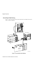
To connect a peripheral to a DHW42-BB asynchronous port using the H3104 harmonica,
refer to Figure 2-16 and follow these steps:
1.
Set the ON/OFF switch on the peripheral to the OFF (O) position.
2.
Make sure that the 120-pin-to-2 x 36-pin cable supplied with your DHW42-BB is
installed. (Figure 2-16, Item 1)
3.
Connect the straight connector of the BC16C-10 cable to one of the asynchronous
cable ports on the back of the system unit. (Figure 2-16, Item 2)
4.
Close the bail lock loops on each side of the connector.
5.
Connect the angled connector of the BC16C-10 cable to the H3104 harmonica.
6.
Close the bail lock loops on each side of the connector.
7.
Connect one end of a DEC423 cable to one of the eight MMJ ports on the harmonica.
8.
Connect the other end of the DEC423 cable to a DEC423 port on the peripheral.
9.
Set the ON/OFF switch on the peripheral to the ON (l) position.
2-20 MicroVAX 3100 Models 88/98 User Information
Getting Started
1
2
MLO-013620
Figure 2-16 Connect a DHW42-BB Asynchronous Port
MicroVAX 3100 Models 88/98 User Information 2-21
Getting Started
Connecting Peripherals to a DHW42-CB Option
If the system has the DHW42-CB asynchronous communications option installed, the
system has two four-line asynchronous ports with modem control. You can connect up to
four peripherals to each of these ports using the breakout cable (BC29J-06) supplied with
the option.
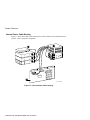
To connect a peripheral to an asynchronous port, refer to Figure 2-17 and follow these
steps:
1.
Set the ON/OFF switch on the peripheral to the OFF (O) position.
2.
Make sure that the 120 pin to 2 x 50 pin cable supplied with the DHW42-CB is
installed. (Figure 2-17, Item 1)
3.
Hold in the connector clips on either side of the 50-pin connector of the breakout
cable and connect it to one of the asynchronous cable ports on the back of the system
unit. (Figure 2-17, Item 2)
4.
Release the clips. The hooks on the port secure the connector in place.
5.
Connect one of the four EIA-232 connectors on the breakout cable to the peripheral.
6.
Set the ON/OFF switch on the peripheral to the ON (l) position.
2-22 MicroVAX 3100 Models 88/98 User Information
Getting Started
1
2
MLO-013621
Figure 2-17 Connecting to a DHW42-CB Asynchronous Port
MicroVAX 3100 Models 88/98 User Information 2-23
Getting Started
Connecting Peripherals to an Optional Synchronous Port
If the system has the DSW43-AA synchronous communications option installed, the
system has two synchronous modem ports. The EIA-232/V.24 cable (BC19D-02) is the
standard cable shipped with the option. If you are using a synchronous interface standard
other than EIA-232/V.24, use one of the optional cables listed in Table 3-3.
To connect a peripheral to a synchronous port, refer to Figure 2-18 and follow these steps:
1.
Set the ON/OFF switch on the peripheral to the OFF (O) position.
2.
Connect the 100-pin-to-2x50-pin cable, supplied with your DSW43-AA. (See Figure
2-18, Item 1).
3.
Connect the 50-pin connector of the option cable to one of the synchronous cable
ports on the back of the system unit. (See Figure 2-18, Item 2).
4.
Connect the other connector of the option cable to the communications port on the
peripheral.
5.
If the option cable connectors are fitted with screws, secure the connectors to the ports
by tightening them on each side.
6.
Set the ON/OFF switch on the peripheral to the ON (l) position.
2-24 MicroVAX 3100 Models 88/98 User Information
Getting Started
1
2
MLO-013622
Figure 2-18 Connecting to a DSW43-AA Synchronous Port
MicroVAX 3100 Models 88/98 User Information 2-25
Getting Started
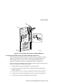
Installing a SCSI Terminator on an Optional KZDDA
If you are installing a SCSI terminator, refer to Figure 2-19 below.
MLO-013702
Figure 2-19 Installing a SCSI Terminator on an Optional KZDDA
2-26 MicroVAX 3100 Models 88/98 User Information
Getting Started
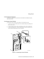
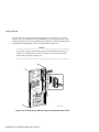
Connecting the Power Cord
_________________________ Caution ___________________________
Your system uses a momentary switch for On/Off control. Always assume that
your system will come on when the AC power cord is installed.
____________________________________________________________
To connect the power cord, refer to Figure 2-20 and follow these steps:
1.
Connect the power cord to the rear of the system.
2.
Connect the other end of the power cord to an isolated, grounded circuit.
MLO-013702
Figure 2-20 Connecting the Power Cord
MicroVAX 3100 Models 88/98 User Information 2-27
Getting Started
Starting Your System
To turn on the system, refer to Figure 2-21 and follow these steps:
1.
Verify your system is OFF by the Power LED indicator.
2.
Turn on the console terminal. Wait until it completes its power-up self test. See the
terminal documentation for more information.
3.
Connect the other end of the power cord to an isolated, grounded circuit.
4.
Turn on the system unit by momentarily pushing in the On/Off switch until the Power
LED is illuminated.
MLO-013608
Figure 2-21 Turning the System On
2-28 MicroVAX 3100 Models 88/98 User Information
Getting Started
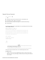
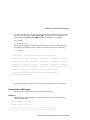
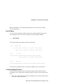
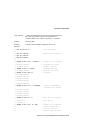
Checking the Power-Up Test Results
The power-up test can take several minutes to complete, depending on the number of
installed options you have and on which default settings you use:
A. If the power-up test results on the screen are similar to the results shown below, the
system has passed the power-up test.
B. If the power-up test results on the screen are not similar to the results shown below,
the system has not passed the power-up test. Go to sub-step 1.
KA58-A or KA59-A
V1.0, VMB 2.16
Performing normal system tests.
74..73..72..71..70..69..68..67..66..65..64..63..62..61..60..59..
58..57..56..55..54..53..52..51..50..49..48..47..46..45..44..43..
42..41..40..39..38..37..36..35..34..33..32..31..30..29..28..27..
26..25..24..23..22..21..20..19..18..17..16..15..14..13..12..11..
10..09..08..07..06..05..04..03..
Tests completed.
>>>
Central Processing Unit (CPU) name, Firmware version number, and Virtual Memory
Boot (VMB) version number
Read-Only Memory (ROM) based diagnostics countdown
Status message
Console prompt
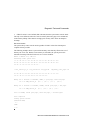
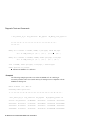
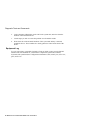
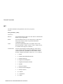
1.
Write down the error messages and the error summaries. the following example shows
an error message and an error summary.
2.
Turn the system OFF and remove AC power cord..
3.
Make sure that all the connections you made in step 3, step 4, step 5, and step 6 are
correct.
4.
Attach the AC power cord and turn the system ON.
5.
If an error report is still displayed, see the Troubleshooting chapter in this manual.
MicroVAX 3100 Models 88/98 User Information 2-29
Getting Started
KA58-A or KA59-A
V1.0, VMB 2.16
Performing normal system tests.
74..73..72..71..70..69..68..67..66..65..64..63..62..61..60..59..
? Test_Subtest_31_05 Loop_Subtest=00 Err_Type=FF
Vec=0000 Prev_Errs=0000
P4=00010000
P1=00000000
DE_Memory_Setup_CSRs.lis
P2=01000000
P5=2101801C P6=00000007 P7=80000003 P8=0000CF4A
P9=00000001 P10=2006B8D8
r0=00000002 r1=21018000 r2=00000008 r3=81000000
r4=00000001
r5=01000000
r6=2006EB77 r7=21018048 r8=00000000 r9=20140758 r10=00000000 r11=FFFFFFFF
dser=0000 cesr=00000000 intmsk=00 icsr=01 pcsts=FA00 pcadr=FFFFFFF8
pcctl=FC13
cctl=00000020 bcetsts=0360 bcedsts=0F00 cefsts=00019200 nests=00
mmcdsr=01FE6600 mesr=00000000
58..57..56..55..54..53..52..51..50..49..48..47..46..45..44..43..
42..41..40..39..38..37..36..35..34..33..32..31..30..29..28..27..
26..25..24..23..22..21..20..19..18..17..16..15..14..13..12..11..
10..09..08..07..06..05..04..03..
Memory Set 0: 00000000 to 00FFFFFF, 16MB, 32768 good pages, 0 bad pages
Set 0 on SIMM_carrier_J4
(J5...)
(J6...)
(7...)
(J8??)
Total of 16MB, 32768 good pages, 0 bad pages, 104 reserved pages
Normal operation not possible.
Error message
Error summary
Power-up test completion
Specific error information on the test that failed
Status message
2-30 MicroVAX 3100 Models 88/98 User Information
P3=00000001
Getting Started
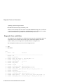
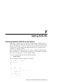
Testing the Ethernet Installation
When you complete the network installation procedure, follow
these steps to test the installation:
1.
Attach your power cord and turn the system ON.
2.
Enter the following command to test the installation:
>>>T 5F
>>>
3.
Run test 5F with the first parameter set to 0 (default) to test
the SGEC chip using internal loopback mode. An example of
success is shown by the console prompt returning without any
messages as shown in the next two examples.
>>>T 5F
>>>
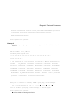
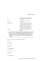
4.
Another example of test success is shown with test 5F first
parameter set to 1 to test the SGEC chip using external
loopback mode. This requires a terminator on the selected
Ethernet port, either thin wire or thick wire. If the test is run
while connected to an active net, it may fail.
>>>T 5F
>>>
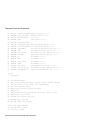
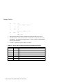
5.
If the device fails the self-test, the system responds with a
display similar to the following:
>>>T 5F
? Test_Subtest_5F_18
Vec=010C
Loop_Subtest=0E
Prev_Errs=0000
Err_Type=FF
DE_SGEC.lis
P1=00000001
P2=00000000
P3=827DFF03
P4=00000000
P5=00000000
P6=00000000
P7=00000000
P8=00000001
P9=00000000 P10=00000000
r0=00000054
r1=000082E2
r2=00000001
r3=000082FA
r4=00008230
r6=000082E2
r7=20008000
r8=00008000
r9=20140758
r5=00000040
r10=13000001 r11=2014044B
EPC=2005721A dser=0000 cesr=00000000 icsr=01 pcsts=F800 pcctl=FC13
cctl=00000007 bcetsts=03A0 bcedsts=0400 cefsts=00019200 nests=00
mmcdsr=00C6C600 mesr=00006000
>>>
MicroVAX 3100 Models 88/98 User Information 2-31
Getting Started
6.
If the device fails, see Chapters 5, Troubleshooting, and 6,
Diagnostic Tests and Commands.
Completing the Ethernet Installation
The network coordinator must complete the installation. You must
give the following information to the network coordinator:
•
A unique node name comprised of a maximum of six
alphanumeric characters.
Choose a node name and ask the network coordinator to make
sure that the node name is unique on the network.
•
The system's Ethernet address
To determine the system's Ethernet address, follow these steps:
1.
Enter the following command at the console prompt:
>>>SHOW ETHERNET
The system displays a response similar to the following:
ETHERNET = 08-00-2B-1A-0B-BB
The alphanumeric string, shown in the form nn-nn-nn-nn-nn-nn, is
the Ethernet address.
2.
Write down the Ethernet address and give it to the network
coordinator.
If the Network Installation Fails
If the network installation fails, contact your Digital services
representative.
Removing the System Unit from a Network
The following subsections describe how to remove the system unit
from a network.
2-32 MicroVAX 3100 Models 88/98 User Information
Getting Started
__________________________ Note _____________________________
Before removing the system unit from a network:
• Get the approval of the network coordinator.
• See the operating system documentation for
information on the shutdown procedures before
stopping or turning off the system.
• If the system is the server in a network, do not turn off,
halt or restart the system without notifying the other
network members.
____________________________________________________________
Removing the System Unit from a ThinWire Ethernet Cable
To remove the system unit from a ThinWire Ethernet cable,
follow these steps:
1.
Power the system off.
_________________________ Caution ___________________________
Disconnecting the ThinWire Ethernet terminator or the
ThinWire Ethernet cable connectors from the T-connector
may cause disruptions to network communications.
____________________________________________________________
2.
Disconnect the entire T-connector from the system (see
Figure 2-10 and add a terminator to the ThinWire port on the
back of the system unit (seeFigure 2-11).
Removing the System Unit from a ThickWire Ethernet Cable
To remove the system unit from a ThickWire Ethernet cable,
follow these steps:
1.
Power the system off.
2.
Disconnect the transceiver cable from the ThickWire
Ethernet connector on the back of the system unit (see Figure
2-11 and replace it with a terminator (see Figure 2-10).
MicroVAX 3100 Models 88/98 User Information 2-33
Getting Started
Booting the Operating System
The system is supplied with factory installed software (FIS) on the system disk. Boot the
operating system following the procedures in the OpenVMS Factory Installed Software
User Guide.
Turning Off Your System
Before turning off your system, make sure to save and close all open files. If you turn the
system off without saving and closing files, you could corrupt some or all of your data.
To turn off your system, follow this procedure:
1.
Close any application data files you have open as well as any applications you have
running. Most application programs prompt you to save the information before
closing.
2.
Shut down the operating system by typing the following from a privileged account:
@sys$system:shutdown
3.
Wait for the operating system to complete the shutdown process and you are prompted
to use the halt button to get to the console prompt (>>>).
4.
Do not turn off power to your system and peripherals until the shutdown sequence
completes, and you are at the console prompt (>>>).
Computer Security
When the security password is set, there are two types of users: privileged users and
unprivileged users. Privileged users know the security password and can use the full range
of console commands; unprivileged users can only use the following commands:
•
LOGIN--use this command with the security password to become a privileged user.
•
BOOT-- Use this command without parameters to boot the operating system when the
boot device has been set.
See Appendix B for more information on console security and setting the password.
Posture and Work Habits
If you use poor posture while you work or if your equipment is poorly positioned, personal
injury may result (as suggested by certain recent scientific articles). Although other articles
suggest that there is no cause and effect, we strongly recommend that you read and follow
the precautions outlined in Figure 2-22 and Table 2-1. In addition, be sure to adjust your
work area so that you are comfortable.
2-34 MicroVAX 3100 Models 88/98 User Information
Getting Started
Figure 2-22 Recommendations for Posture and Work Habits
Table 2-1 Recommendations for Posture and Work Habits
Adjust
Chair
Figure
Callout
To allow the following conditions:
1
Your feet are flat on the floor.
2
Your legs are vertical and form a right angle to the floor.
3
Your thighs are horizontal, and they are not bearing weight. To
prevent restriction of the blood flow, keep the backs of your
knees away from the seat so you do not compress the area
behind them.
4
Your upper body is erect and your lower back is supported with
a backrest.
MicroVAX 3100 Models 88/98 User Information 2-35
Getting Started
Adjust
Keyboard
Figure
Callout
5
6
To allow the following conditions:
Your wrists are straight and do not flex more than 15 degrees.
They are supported and do not rest on sharp edges. If you use a
mouse, rest your hand on the mouse so your wrist is not on the
work surface.
Your upper arms are straight down at your sides, and your
elbows are close to your sides and support your arm weight.
Forearms are at a 70- to 90-degree angle.
Head
7
Avoid neck strain. Your head should incline downward, but no
more than 15 to 20 degrees.
Terminal
8
The terminal should be no higher than the level of your eyes and
at the correct distance for your vision.
9
Avoid eye fatigue, which can be caused by glare, image quality,
uncomfortable furniture, eye height, and uncorrected vision. If
you cannot focus to read at different distances, you may need
special glasses. Relax your eyes periodically by focusing on
distant objects.
Lighting
Direct lighting or sunlight on the screen causes glare and
reflections. Place lighting behind or to the side of your work
area, and distribute the lighting evenly on your work area.
2-36 MicroVAX 3100 Models 88/98 User Information
Getting Started
Table 2-1. Recommendations for Posture and Work Habits (continued)
Adjust
Figure
Callout
To allow for the following conditions:
Noise
Keep background noise at a minimum. Background noise above
65 dBa is tiring. Sound-absorbing materials (for example,
curtains, carpeting, and acoustic tile) can help reduce
background noise.
Temperature
The temperature should be between 20° and 23°C (68° and 74°
F).
Humidity
The humidity should be between 30% and 70%.
Ventilation
Provide adequate air ventilation to operate the equipment and
avoid fatigue.
Work Area
Your work area should be greater than 70 cm (28 inches) center
to center, preferably 152 cm (60 inches).
________________________WARNING __________________________
If you experience pain or discomfort while using your system, rest and
review the instructions for posture and work habits. If the pain or
discomfort continues after resuming work, discontinue use and report the
condition to your job supervisor or physician.
____________________________________________________________
MicroVAX 3100 Models 88/98 User Information 2-37
3
Installing Hardware Options
Introduction
This chapter covers the following topics related to installing system options on the Digital
MicroVAX 3100 Model 88 and Model 98 Systems:
•
Opening and closing the system cover
•
Installing additional system memory
•
Installing internal drives
•
Installing I/O communications options
•
Connecting external devices
•
Cable layout for power, and SCSI
________________________ CAUTION ___________________________
a.
To avoid damage from static discharge, touch bare (unpainted) metal on the
system box before you touch anything inside the system.
b. To avoid damage from overheating, system covers must be in place when
running the system for extended periods of time.
____________________________________________________________
MicroVax 3100 Models 88/98 User Information 3-1
Installing Hardware Options
Removing the Cover
To gain access to the inside of the MicroVAX 3100 Model 88 and Model 98 Systems,
remove the cover following this procedure:
1.
Turn off your system, the terminal, and all external peripheral devices.
2.
Unplug the power cord from the wall outlet.
3.
Wait at least 15 seconds, to allow time for the power supply capacitors to discharge
safely.
4.
Facing the rear of the unit, locate and loosen the three thumbscrews that fasten the top
cover to the enclosure. Pull back on the cover sides two or three inches, and lift the
cover up and away from the enclosure.
1
MLO-013628
Figure 3-1 Removing the Cover
3-2 MicroVAX 3100 Models 88/98 User Information
Installing Hardware Options
Cache Memory
The MicroVAX 3100 Model 88 system has 128 KB of cache on the system board; the
MicroVAX 3100 Model 98 system has 512 KB of on board cache.
System Memory
The MicroVAX 3100 Model 88 and Model 98 Systems have one bank of four Single-InLine Memory Modules (SIMMs) with 16 MB each, for a total of 64 MB. The MicroVAX
Model 98 also has the option of being supplied with SIMMs of 32MB each, for a total of
128 MB. There are slots for a second optional bank of memory. The memory options
include adding a second bank of 16 MB SIMMs (196 MB total), a second bank of 32 MB
SIMMs (256 MB total) or a set of 32 MB SIMMs to replace the first bank (256 MB total
for both banks) on the MicroVAX 3100 Model 88. As available, a second SIMM carrier
will increase maximum memory to 512MB.
Memory Configuration Rules
Refer to Figure 3-2 for SIMM Bank Configuration.
•
Random-access memory can be added only in four SIMM increments (four per bank).
•
There are two banks, J1-J4 and J-5-J8. Always fill at least one bank completely.
•
To fill a bank, start at one end of Bank J8-J5 and fill every SIMM socket in the bank.
Each bank MUST be completely filled with like SIMMs, if it is filled at all.
•
Do not mix SIMMs within a bank
•
Use same SIMM size within a bank.
MicroVAX 3100 Models 88/98 User Information 3-3
Installing Hardware Options
J1
J2
J3
J4
J5
J6
J7
J8
MLO-013629
Figure 3-2 SIMM Bank Configuration
Installing or Removing Memory Modules (SIMMs)
To add or remove a set of memory modules (SIMMs) to a bank, see Figure 3-3 and follow
this procedure:
1.
Turn off your system and unplug the power cord from the wall outlet.
2.
Unlock and remove the thumbscrews that secure the top cover and remove the cover,
as described earlier in this chapter.
3.
Remove the SIMM board by pushing back on the latches and lifting it out of its
connector.
3-4 MicroVAX 3100 Models 88/98 User Information
Installing Hardware Options
2
1
MLO-013650
Figure 3-3 Removing the SIMM Board
4.
Hold the SIMM board so that the bottom side of the SIMMs face toward you.
Remove the first SIMM from connector J4 by tilting the top of it gently toward you
and lifting it out.
5.
Remove the optional SIMM board from connector J1 in the same manner as described
in the previous step. Remove all other SIMMs in the same manner.
MicroVAX 3100 Models 88/98 User Information 3-5
Installing Hardware Options
MLO-013651
Figure 3-4 Removing/Installing a SIMM Board
5.
Install/reinstall the SIMMs as desired by tipping the top of the SIMM to be placed
furthest from you toward you, and inserting its base in the appropriate connector.
Install the other SIMMs in the same manner, working toward you.
6.
Reinstall the SIMM board.
7.
Replace the cover, and secure with thumbscrews, as described earlier in this chapter.
8.
Connect the power cord and plug it into the wall outlet.
Storage Devices
MicroVAX 3100 Model 88 and Model 98 Systems support six storage devices, one
standard RRDxx CD-ROM drive, one standard RZ2x disk drive, two slots for either 3.5inch or 5.25-inch removable media or non-removable media devices, and two additional
slots which can accommodate only 1 inch x 3.5-inch hard drives. See Figure 3-6 or
Figure 3-10.
General Information on Installing Drives
This section covers general drive installation information, including internal and external
SCSI drives, external SCSI, and cable layouts.
3-6 MicroVAX 3100 Models 88/98 User Information
Installing Hardware Options
SCSI Addresses (SCSI ID’s)
Before installing a SCSI device, you must either set or verify the setting of the device’s
SCSI address (SCSI ID). The SCSI controller chip is normally assigned device ID seven.
Digital recommends that you use Table 3-1 as a guide for the selection of an address for
your SCSI drive.
Table 3-1 SCSI Address Recommendations
SCSI Address (ID)
Device (Drive) Recommended
0
Expansion
1
Expansion/hard drive
2
Expansion/hard drive
3
System disk (where your operating system resides)
4
CD-ROM drive
5
Expansion
6
Host Adapter (SCSI Controller) default
7
Expansion
Refer to Appendix F, Setting SCSI Ids, and the section on SCSI Connectors in
Appendix E, Technical Specifications, for additional information.
________________________ CAUTION ___________________________
Failure to properly set up the SCSI termination may result in loss of data or
damage to the file system.
____________________________________________________________
SCSI Termination
MicroVAX 3100 Model 88 and Model 98 Systems contain an embedded SCSI bus that is
used to connect both the internal and external drives. Both ends (and only at the ends) of
the SCSI bus MUST be terminated correctly. The controller end of the bus has embedded
termination.
External SCSI Connector Termination
An external terminator is required when the SCSI port is not being used.
MicroVAX 3100 Models 88/98 User Information 3-7
Installing Hardware Options
Internal SCSI Termination
The internal SCSI cable used for the MicroVAX 3100 Model 88 and Model 98 Systems is
a flat ribbon cable with integrated on-board termination. Therefore, NO storage devices
should have termination enabled.
SCSI Bus Length
The total SCSI bus length, including internal cables and etch on the motherboard as well
as the external cables between the system and the storage enclosures must not exceed 6
meters (19.6). The internal SCSI length is 1.2 meters (3.9 feet), leaving 4.8 meters (16.2
feet) for external SCSI use.
Installing Optional Storage Devices
This section tells you how to install optional hard devices into the front and rear storage
bays.
To install an optional storage device, follow this procedure:
1.
Turn off your system and unplug the power cord from the wall outlet.
2.
Remove the cover, as described earlier in this chapter.
Installing Devices in the Front Bay
There are four slots in the front drive bay; the top slot contains the standard 3.5-inch RZxx
hard disk drive. The next two can accommodate optional 3.5-inch or 5.25-inch devices,
while the lowest slot contains the CD-ROM drive.
_________________________ NOTE____________________________
•
The two middle slots in the front drive bay can accommodate either 3.5inch or 5.25-inch devices. If you are installing 3.5-inch devices, there are
additional brackets which must be mounted on the device before it is
installed in the slot.
___________________________________________________________
3-8 MicroVAX 3100 Models 88/98 User Information
Installing Hardware Options
To install the brackets on a 3.5-inch device, refer to Figure 3-5 and follow these steps:
1.
Align the device as shown in Figure 3-5 with the internal cable connectors facing
away from you. The SCSI connector should be oriented at the rear of the assembly.
2.
Attach the brackets to the device using the four screws provided.
1
MLO-013520
Figure 3-5 Installing the 3.5 Inch Brackets
To install either 3.5-inch optional drives (with mounting bracket attached), or 5.25-inch
devices in the front drive bay, follow these steps.
1.
Turn off the system, unplug the power cord and remove the cover.
2.
Set the SCSI drive device jumpers or switches for the desired SCSI ID (address). This
address depends on the unit numbers currently in use. (See Appendix F, Setting SCSI
IDs, for a list of typical SCSI ID assignments. Appendix G, Equipment Log, contains
space to record your systems SCSI ID assignments.) Follow the guidelines in the
manual that came with the drive.
3.
Remove the enclosure front bezel by pushing on the inside tab and lifting it up and
away from the front of the enclosure as shown in Figure 3-6.
MicroVAX 3100 Models 88/98 User Information 3-9
Installing Hardware Options
ML013593
Figure 3-6 Removing the Front Bezel
4.
5.
6.
Remove the EMI shield covering the slot you are filling by pushing it out from the
inside of the enclosure. Refer to Figure 3-7, Item .
Attach the drive rail, Figure 3-7, Item onto the device (or onto the mounted bracket
if you are installing a 3.5-inch device) using the screws provided.
Insert the rear of the device through the front of the bay and slide it rearward in the
bay, engaging the bay tabs onto the drive rail. If you are installing a non-removable
media device (such as a disk drive) seat it so that the front is flush with the front of the
3-10 MicroVAX 3100 Models 88/98 User Information
Installing Hardware Options
enclosure; seat removable media devices (such as a CD-ROM) so that the front will be
even with the front of the bezel after it is reinstalled.
7.
Insert the screws, Figure 3-7 Item (four total) , through the side of the bay and into
the device as shown. It may be necessary to position the rail slightly to seat it in the
system.
3
4
1
2
MLO-013611
Figure 3-7 Installing Optional Devices in the Front Bay
8.
If you are installing a hard drive or other non-removable media device, snap the front
EMI shield back into place over the slot in the enclosure. If you are installing a CDROM or other removable media device, you will leave the EMI shield off the system
so that the front of the device can be accessed. Place the shield in a safe location in
case you wish to remove the device later, or replace it with a hard drive.
9.
Connect the SCSI and power cables to the device.
10. Reinstall the front bezel, close the cover, connect the power cord and plug it into the
wall outlet.
MicroVAX 3100 Models 88/98 User Information 3-11
Installing Hardware Options
Installing a Hard Disk Drive in the Rear Storage Bay
One or two optional 1 inch x 3.5-inch hard disk drives can be installed in the rear storage
bay.
To install a hard disk in this bay, refer to Figure 3-8 and follow these procedures:
1.
Turn off the system, unplug the power cord and remove the cover.
2.
Remove the two screws which holds the rear drive bay in place.
Slide the flanges of the bay out of their retaining slots , and lift the bay out of the
enclosure.
2
1
MLO-013610
Figure 3-8 Removing the Rear Drive Bay
3.
Set the SCSI drive device jumpers or switches for the desired SCSI ID (address). This
address depends on the unit numbers currently in use. (See Appendix F, Setting SCSI
IDs, for a list of typical SCSI ID assignments. Appendix G, Equipment Log, contains
space to record your systems SCSI ID assignments.) Follow the guidelines in the
manual that came with the drive.
3-12 MicroVAX 3100 Models 88/98 User Information
Installing Hardware Options
4.
Set the drive into position in the bay (fill the bottom slot of the bay first, as shown in
Figure 3-9, and place the second drive on top of the first).
5.
Insert the four screws through the side of the bay and into the device as shown.
MLO-013597
Figure 3-9 Installing Optional Hard Drives in the Rear Bay
6.
Reinstall the bay into the enclosure slots and replace the two screws.
7.
Connect the SCSI and power cables to the device.
8.
Close the cover, connect the power cord and plug it into the wall outlet.
MicroVAX 3100 Models 88/98 User Information 3-13
Installing Hardware Options
Communications Options
There are five slots on the rear of the MicroVAX 3100 88/98 systems available for
communications options. The slots are numbered 1 through 5, from bottom to top
(numbers are visible from the inside of the chassis). Slot 5 may be used for synchronous
communication, Slot 4 asynchronous communication, Slots 3 and 4 are reserved for future
use and Slot 1 functions as an optional external SCSI port. Refer to Figure 3-10.
5
4
3
2
1
MLO-013716
Figure 3-10 Communication Slots
3-14 MicroVAX 3100 Models 88/98 User Information
Installing Hardware Options
Table 3-2 Communication Option Slot Locations
Figure Legend
Communication Device
1
KZDDA (External SCSI)
2
Reserved
3
Reserved
4
DSW43 (Synchronous)
5
DHW42 (Asynchronous)
Synchronous Communication Option
The MicroVAX 3100 88/98 systems support the DSW43-AA synchronous communications
option. This communications option provides two synchronous communications ports and
allows you to connect the system to a peripheral that uses an EIA-232 (V.24) 25-pin
connector via a 2-ft cable. You can use other interface standards with this option if you
order different cables. Table 3-3 lists each interface standard and the part number of the
corresponding cable. The BC19x-02 cables listed in are 2-foot cables; you must order the
extension cables separately. Contact your Digital sales representative for information on
ordering any of the different cables that support these interface standards.
Table 3-3 Interface Standards and Cable Part Numbers
Interface Standard
Cable Part Number
Extension Cable Part Number
EIA-232/V.24
BC19D-02
BC22F-nn (10, 25, or 50 ft)
EIA-432/V1.0
BC19E-02
BC55D-nn (25 or 50 ft)
EIA-422/V.11
BC19B-02
BC55D-nn (25 or 50 ft)
Installing the Synchronous Communication Option
The MicroVAX 3100 88/98 systems support the DSW43-AA synchronous communications
option. To install it, refer to Figure 3-11 and follow these instructions:
1.
Turn off the system, unplug the power cord and remove the cover.
2.
Insert the module into the slot of the I/O receiver, pressing it firmly into place to seat
the connection.
MicroVAX 3100 Models 88/98 User Information 3-15
Installing Hardware Options
1
2
MLO-013625
Figure 3-11 Installing the Synchronous Communication Option
3.
Insert the screw through the module and into the I/O shelf as shown.
4.
Connect the 100-pin-to-2x50-pin pigtail cables to the new synchronous
communications option.
5.
Close the cover, connect the power cord and plug it into the wall outlet.
Asynchronous Communication Options
The MicroVAX 3100 88/98 systems support two different asynchronous communications
options. These options are as follows:
•
DHW42-BB -- This asynchronous option provides 16 asynchronous DEC423 dataline-only communications lines through two system ports. You can connect up to 16
peripherals using the MMJ ports on two harmonicas (H3104) that connect to the
option cables (BC16C-10).
3-16 MicroVAX 3100 Models 88/98 User Information
Installing Hardware Options
Use the following cables instead of the BC16C-10 cable if you require longer cable
lengths:
BC16C-25, BC16C-50, BC16C-A0, or BC16C-B5.
Use the following cables between the harmonica (H3104) and the DEC423 peripheral:
BC16E-10, BC16E-25, or BC16E-50.
•
DHW42-CB -- This asynchronous option provides eight asynchronous EIA-232
modem control lines through two system ports using two breakout cables (BC29J-06).
Attach one of the following cables to a connector on the breakout cable if you require
longer cable lengths:
BC22F-10, BC22F-25, or BC22F-50.
The peripheral you are using may require a null-modem extension cable. See the
peripheral documentation or contact your Digital sales representative for information on
the correct null-modem cable to use.
Installing the Asynchronous Communication Option
The MicroVAX 3100 88/98 systems support two different asynchronous communications
options, DHW42-BB and DHW42-CB in the top slot of the I/O receiver. To install either
of these, refer to Figure 3-12 follow these instructions:
1.
Turn off the system, unplug the power cord and remove the cover.
2.
Insert the module into the top slot of the I/O receiver, pressing it firmly into place
to seat the connection.
MicroVAX 3100 Models 88/98 User Information 3-17
Installing Hardware Options
1
2
MLO-013626
Figure 3-12 Installing the Asynchronous Communication Option
3.
Insert the screw through the option and into the I/O shelf as shown.
4.
Connect the 120 pin-to 2 x 36 or the 120 pin-to- 2 x 50 pin pigtail cables to your new
asynchronous communication option.
5.
Close the cover, connect the power cord and plug it into the wall outlet.
Optional SCSI Port (KZDDA)
The MicroVAX 3100 88/98 systems supports seven additional external SCSI devices with
the KZDDA option.
3-18 MicroVAX 3100 Models 88/98 User Information
Installing Hardware Options
Installing the KZDDA
The KZDDA external SCSI option is installed in the bottom I/O slot. To install the
KZDDA option, refer to Figure 3-13 and follow these instructions:
1.
Turn off the system, unplug the power cord and remove the cover.
2.
Insert the module into the bottom slot of the I/O receiver, pressing it firmly into
place to seat the connection.
1
2
MLO-013627
Figure 3-13 Installing the KZDDA External SCSI Option
3.
Insert the screw through the option and into the I/O shelf as shown.
4.
Attach external SCSI cable.
5.
Close the cover, connect the power cord and plug it into the wall outlet.
MicroVAX 3100 Models 88/98 User Information 3-19
Installing Hardware Options
External Options
The MicroVAX 3100 88/98 systems can accommodate the following options:
•
SCSI devices and expansion boxes
•
Printers, terminals, modems, and other devices that use asynchronous or synchronous
connectors
Your Digital sales representative can give you information on how to order a full range of
SCSI and Q-bus expansion boxes, printers, terminals, modems, and other devices that are
compatible with MicroVAX 3100 88/98 systems.
Connecting an External SCSI Option or Expansion Box
________________________ CAUTION __________________________
•
The recommended maximum length of SCSI cables (internal length plus
external length) is 19.6 feet (6 meters).
• Do not connect more than two tape drive devices, per SCSI port.
• Some expansion boxes are restricted to either 110 V ac or (220 V ac)
operation. Make sure that the voltage requirement of the expansion box
used is compatible with the supply voltage.
• Turn on the expansion boxes before you turn on the system unit. This
procedure ensures that the device in each expansion box is ready for use
and that the system firmware includes the device in the configuration
display.
• Do not connect or disconnect SCSI expansion boxes while the system is
turned on. Doing so can cause damage to the equipment or corrupt
data.
• Digital cannot guarantee the correct operation of any SCSI bus that
uses cable assemblies not supplied by Digital or not configured in
accordance with these guidelines.
___________________________________________________________
__________________________ Note ____________________________
Be sure to read the instructions that come with the SCSI device. If the cable
supplied with the SCSI device has the wrong type of connector, you will need an
adapter or a different cable.
___________________________________________________________
3-20 MicroVAX 3100 Models 88/98 User Information
Installing Hardware Options
To connect an external SCSI device, or a SCSI expansion box, follow these steps:
1.
Set the drive jumpers or switches for the desired SCSI ID.
2.
Remove the SCSI terminator and connect the option’s SCSI cable to the port. Be sure
that you use a cable with a SCSI 50-pin high density type connector.
3.
Terminate the new end of the bus at the last external SCSI device, using the
appropriate terminator. Make sure that any other external SCSI devices have their
terminators removed or disabled.
To Check expansion box connections, enter the following from the console prompt:
>>>
SHOW SCSI
SCSI Adapter A, SCSI ID 6
-DKA300 (DEC RZ26N)
-DKA400 (DEC RRD45)
SCSI Adapter B, SCSI ID 6
-DKB100 (DEC RZ28D)
MicroVAX 3100 Models 88/98 User Information 3-21
Installing Hardware Options
System Board Access
To access the system board, the enclosure cover must first be removed, then release the
two module clips and gently slide board out. Refer to Figure 3-14.
1
MLO-013710
Figure 3-14 Removing System Board
3-22 MicroVAX 3100 Models 88/98 User Information
Installing Hardware Options
If you need to access components on the system board that are underneath the plastic cover
, remove the two nuts and the clip . See Figure 3-15.
2
1
3
MLO-013711
Figure 3-15 Removing the System Board Cover
MicroVAX 3100 Models 88/98 User Information 3-23
4
Troubleshooting
Introduction
This chapter describes initial and general troubleshooting as well as the error beep codes.
)
Refer to the documentation supplied with additional options if you are experiencing
problems with specific options that you have installed.
Initial Troubleshooting
To troubleshoot your MicroVAX 3100 Model 88/98 system initially, follow this
procedure:
1.
Check that the power indicator is on.
2.
Check the power indicator on the terminal.
3.
Make sure that all cables and connections are secure.
4.
Press the Halt/Reset button. If your system fails to boot, turn it off, wait 20 seconds,
and turn it back on.
5.
Contact your Digital service representative or service provider for software- or
hardware-related problems by calling 1-800-354-9000 or 1-800-DIGITAL.
__________________________NOTE ____________________________
If you need to return a failed component, pack it in its original container and
return it to Digital Equipment Corporation or to your service provider.
____________________________________________________________
MicroVax 3100 Models 88/98 User Information 4-1
Troubleshooting
General Troubleshooting
Tables 4-1 through 4-4 list how to identify and solve problems that could occur with your
system, disk drive, and terminal.
Table 4-1 System Troubleshooting
Problem
Possible Cause
Action
Power indicator not on.
System is not plugged in.
Turn off the system, plug it in,
and then turn it back on again.
No power at the wall outlet.
Use another wall outlet.
Power supply failure.
Contact your service
representative.
Internal power supply cables
not reconnected after
installing options.
Reconnect cables.
The overload protection
circuitry of the power
supply may have shut down
because of abnormal
condition on the power line.
Turn the system off, then turn it
back on.
4-2 MicroVAX 3100 Models 88/98 User Information
Troubleshooting
Problem
Possible Cause
Action
Power is on, but there is no
screen display.
Brightness and contrast
controls are not correctly
set.
Adjust the brightness and contrast controls.
Terminal is off.
Turn on the terminal.
Terminal cable or power
cord is incorrectly installed.
Check all terminal connections:
ensure that the terminal is
connected to port 3.
Fuse may be blown on the
terminal.
Replace the fuse.
Terminal settings may be
incorrect.
Check the terminal settings; see
terminal documentation.
Try another terminal.
Terminal is defective.
Replace the video terminal
Port to which the terminal
connects may be faulty.
Try connecting the terminal to
another system. If this solution
works, the port to which the
terminal was connected is
faulty. If the terminal still does
not operate, it is faulty. In either
case, contact your Digital
services representative.
The terminal cable may be
faulty.
Connect the cable to another
system and terminal. If that
terminal now does not work,
the cable is faulty. Contact your
Digital services representative
for a new one.
The break/enable switch is
in the wrong position.
Turn off the system. Set the
break/enable switch to the down
position, then turn the system
on.
MicroVAX 3100 Models 88/98 User Information 4-3
Troubleshooting
Table 4-1 System Troubleshooting (continued)
Problem
Possible Cause
Action
The power up test display
contains unexpected
characters.
The terminal settings are
incorrect, or the console
circuitry is faulty.
Make sure the settings are
correct, then run the power-up
test again. If the terminal is set
correctly, and trouble persists,
contact your Digital services
representative.
The system fails to boot the
operating system.
The system defaults are
incorrectly set.
Set the system defaults as
described in the OpenVMS
Factory Installed Software User
Guide, then try booting the
system again. If the system fails
to boot, contact your Digital
services representative.
No response to keyboard
commands.
Keyboard is not connected.
Connect the keyboard to the
keyboard port.
Table 4-2 Disk Drive Troubleshooting
Problem
Possible Cause
Action
Hard disk drive cannot read
or write information
Incorrect disk drive jumper
settings.
Refer to the disk drive
installation instructions.
Loose or incorrectly
installed cables.
Make sure all cables are
correctly installed.
SCSI hard disk drive is not
correctly formatted or
partitioned.
Format and partition as required
using the supplied operating
system.
4-4 MicroVAX 3100 Models 88/98 User Information
Troubleshooting
Table 4-3 Terminal Troubleshooting
Problem
Possible Cause
Action
Terminal power indicator is
not on.
Terminal is turned off.
Turn on the terminal.
Power cord is not
connected.
Connect the power cord to the
system or a wall outlet.
No power at wall outlet.
Use another outlet.
Power indicator is defective.
Contact your service
representative or Digital
Equipment Corporation.
Terminal incorrectly
adjusted.
Adjust accordingly.
Wrong type of terminal.
Try another terminal.
Defective terminal.
Try another terminal.
Terminal signal cable
incorrectly installed.
Straighten any bent connector
pins and then reconnect the
terminal.
Distorted, rolling, or
flickering screen display, or
wrong or uneven color
MicroVAX 3100 Models 88/98 User Information 4-5
5
Diagnostic Tests and Commands
There are a number of diagnostic tests and commands that can help you to isolate a
problem with the system unit. These tests and commands are as follows:
•
Power-up tests
•
Diagnostic tests and utilities. You can use these tests and commands in privileged
console mode only if the console security feature is enabled and the password is set.
•
Configuration display
•
Error display
Power-Up Tests
The system runs the power-up tests each time you turn on the system. After successful
completion of tests, the system will either enter console mode or proceed to automatic
bootstrap, depending on the HALT action selected by the user.
•
If HALT action is Default, Halt, or Restart, then the system enters console mode.
•
If HALT action is Reboot or Restart_reboot, then the system proceeds to boot.
The following example shows a typical display for a system that passes all tests and then
enters console mode.
KA58-A or KA59-A V1.0, VMB
2.16
Performing normal system tests.
74..73..72..71..70..69..68..67..66..65..64..63..62..61..60..59..
58..57..56..55..54..53..52..51..50..49..48..47..46..45..44..43..
42..41..40..39..38..37..36..35..34..33..32..31..30..29..28..27..
26..25..24..23..22..21..20..19..18..17..16..15..14..13..12..11..
10..09..08..07..06..05..04..03..
MicroVax 3100 Models 88/98 User Information 5–1
Diagnostic Tests and Commands
Tests completed.
>>>
Central Processing Unit (CPU) Name, Firmware Version Number, and
Virtual Memory Boot (VMB) Version Number
Read-Only Memory (ROM) Based Diagnostics Countdown Status Message
Console Prompt
The following example shows a typical display for a system that passes all tests and then
enters automatic bootstrap.
KA58-A or KA59-A V1.0, VMB 2.16
Performing normal system tests.
74..73..72..71..70..69..68..67..66..65..64..63..62..61..60..59..
58..57..56..55..54..53..52..51..50..49..48..47..46..45..44..43..
42..41..40..39..38..37..36..35..34..33..32..31..30..29..28..27..
26..25..24..23..22..21..20..19..18..17..16..15..14..13..12..11..
10..09..08..07..06..05..04..03..
Tests completed.
Loading system software.
(BOOT/R5:0 EZA0)
2..
-EZA0
1..0..
_________________________ NOTE____________________________
The operating system messages start here.
___________________________________________________________
If the power-up tests encounter an error, one of the following actions occurs:
For minor errors:
•
If HALT action is set to a boot condition (that is reboot or restart_reboot), and if a
minor error occurs, the system displays an abbreviated error message and continues to
boot as normal.
5–2 MicroVAX 3100 Models 88/98 User Information
Diagnostic Tests and Commands
•
If HALT action is set to Default, Halt or Restart, then the system enters console mode.
The only errors defined as minor are errors in memory that cause pages to be marked bad
in the memory bitmap. There must be enough good memory left to allow an attempt to
bootstrap.
For severe errors:
The system always enters console mode regardless of HALT action after it attempts to
complete all tests possible.
The following example shows a system with a memory error that only affected one set of
memory out of two sets. Because some memory is still usable, the system proceeds to
automatic bootstrap if the HALT action is set to a boot condition.
KA58-A or KA59-A V1.0, VMB 2.16
Performing normal system tests.
71..70..69..68..67..66..65..64..63..62..61..60..59..58..57..56..
55..54..53..52..51..50..49..48..47..46..45..44..43..42..41..40..
39..38..37..36..35..34..33..32..31..
? Test_Subtest_40_06
Loop_Subtest=00
Err_Type=FF
DE_Memory_count_pages.lis
30..29..28..27..26..25..24..23..22..21..20..19..18..17..16..15..
14..13..12..11..10..09..08..07..06..05..04..03..
Memory Set 0: 08000000 to 09FFFFFF, 32MBs, 0 good pages, 65536 bad pages
Set 0 on SIMM_carrier_J4
(J5...)
(J6...)
(J7...)
(J8 ??)
Memory Set 1: 00000000 to 07FFFFFF, 128MBs, 262144 good pages, 0 bad pages
Set 1 on SIMM_carrier_J4
(J1..)
(J2..)
(J3..)
(J4...
Total of 160MBs, 262144 good pages, 65536 bad pages, 7 reserved pages
Tests completed.
Loading system software.
(BOOT/R5:0 EZA0)
2..
-EZA0
1..0..
MicroVAX 3100 Models 88/98 User Information 5–3
Diagnostic Tests and Commands
Operating system messages start here.
Abbreviated error message for memory error
Memory errors normally cause the results of a SHOW MEMORY display to occur after the
tests are completed and before continuing. SHOW MEMORY is the most useful command
to determine which memory SIMMs are bad when memory errors occur.
Diagnostic Tests and Utilities
The diagnostic tests and utilities are similar to the power-up tests except that the power-up
tests enable you to test all the devices in the system, whereas the diagnostic tests and
utilities enable you to test single devices and the functions of single devices.
By entering this command, you can see a list of diagnostic tests.
>>> T 9E
>>> SHOW TESTS
Test
#
Address
Name
Parameters
___________________________________________________________________________
20052200
SCB
20055850
De_executive
30
2006A53C
Memory_Init_Bitmap *** mark_Hard_SBEs ******
31
2006AB34
Memory_Setup_CSRs
*********
32
2005D148
NMC_registers
**********
33
2005D324
NMC_powerup
**
34
2005E6D8
SSC_ROM
***
35
2005FB90
B_Cache_diag_mode
bypass_test_mask *********
37
20061590
Cache_w_Memory
bypass_test_mask *********
40
2006B5E0
Memory_count_pages First_set Last_set Soft_errs_allowed *****
41
20068CEC
Board_Reset
42
20061880
Chk_for_Interrupts **********
46
200610C4
P_Cache_diag_mode
bypass_test_mask *********
47
2006AD04
Memory_Refresh
start_a end incr cont_on_err time_seconds *****
48
2006B028
Memory_Addr_shorts start_add end_add * cont_on_err pat2 pat3 ****
*
5–4 MicroVAX 3100 Models 88/98 User Information
Diagnostic Tests and Commands
4A
2006A23C
Memory_ECC_SBEs
4B
2006940C
Memory_Byte_Errors start_add end_add add_incr cont_on_err ******
start_add end_add add_incr cont_on_err ******
4C
20069BA0
Memory_ECC_Logic
start_add end_add add_incr cont_on_err ******
4D
20068FE8
Memory_Address
start_add end_add add_incr cont_on_err ******
4E
20069188
Memory_Byte
start_add end_add add_incr cont_on_err ******
4F
2006B7F4
Memory_Data
start_add end_add add_incr cont_on_err ******
51
2005803C
FPA
**********
52
20058530
SSC_Prog_timers
which_timer wait_time_us ***
53
20058818
SSC_TOY_Clock
repeat_test_250ms_ea Tolerance ***
54
20057C18
Virtual_Mode
********
55
20058E6C
Interval_Timer
*****
56
2006507C
SHAC_LPBCK
From_bus To_bus passes *******
58
20065D24
SHAC_RESET
dssi_bus port_number time_secs not_pres *
59
20062778
SGEC_LPBCK_ASSIST
time_secs **
5C
20062D10
SHAC
SHAC_number *********
5F
200619B8
SGEC
environment no_ram_tests ******
62
20058B1C
console_QDSS
mark_not_present selftest_r0 selftest_r1 *****
63
20058CA4
QDSS_any
input_csr selftest_r0 selftest_r1 ******
80
2005D3C0
CQBIC_memory
bypass_test_mask *********
81
200596CC
Qbus_MSCP
IP_csr ******
82
200598AC
Qbus_DELQA
device_num_addr ****
83
2005A85C
QZA_Intlpbck1
controller_number ********
84
2005BF1C
QZA_Intlpbck2
controller_number *********
85
20059A9C
QZA_memory
incr test_pattern controller_number *******
86
20059F44
QZA_DMA
Controller_number main_mem_buf ********
90
20058494
CQBIC_registers
*
91
20058410
CQBIC_powerup
**
99
2005DC4C
Flush_Ena_Caches
dis_flush_VIC dis_flush_BC dis_flush_PC
9A
20063FB0
INTERACTION
pass_count disable_device *******
9B
20068E48
Init_memory
**
9C
2006631C
List_CPU_registers *
9D
2006C250
Utility
Flags *********
9E
2005903C
List_diagnostics
script_number *
9F
200681CC
Create_A0_Script
**********
C1
20057888
SSC_RAM_Data
*
C2
20057A78
SSC_RAM_Data_Addr
*
C5
200589E8
SSC_registers
*
MicroVAX 3100 Models 88/98 User Information 5–5
Diagnostic Tests and Commands
D0
20060C70
V_Cache_diag_mode
bypass_test_mask *********
D2
2005DE90
O_Bit_diag_mode
bypass_test_mask *********
DA
2006139C
PB_Flush_Cache
**********
DB
2005E850
Speed
print_speed *********
DC
2006C060
NO_Memory_present
*
DD
2005F0DC
B_Cache_Data_debug start_add end_add add_incr *******
DE
2005EC64
B_Cache_Tag_Debug
start_add end_add add_incr *******
DF
2005E2A8
O_BIT_DEBUG
start_add end_add add_incr seg_incr ******
E0
2006D4D4
SCSI
environment reset_bus time_s *******
E1
2006D7CC
SCSI_Utility
environment util_nbr target_ID lun ******
E2
2006DA2C
SCSI_MAP
bypass_test addr_incr_data_tst ********
E4
2006DFC8
DZ
environment *********
E8
2006E1DC
SYNC
environment *********
E9
2006E2B4
SYNC_Utility
environment *********
EC
2006E398
ASYNC
environment *********
F0
2006D638
SCSI_option
environment reset_bus time_s *******
F1
2006D900
SCSI_Opt_Utility
environment util_nbr target_ID lun ******
F2
2006DA40
SCSI_MAP_Option
bypass_test addr_incr_data_tst ********
Scripts
#
Description
A0
User defined scripts
A1
Powerup tests, Functional Verify, continue on error, numeric countdown
A3
Functional Verify, stop on error, test # announcements
A4
Loop on A3 Functional Verify
A6
Memory tests, mark only multiple bit errors
A7
Memory tests
A8
Memory acceptance tests, mark single and multi-bit errors, call A7
A9
Memory tests, stop on error
B2
Extended tests plus BF, then loop
B5
Extended tests, then loop
BF
DZ, SYNC, ASYNC with loopbacks
Load & start system exerciser
100 Customer mode, 2 passes
101 CSSE mode, 2 passes
5–6 MicroVAX 3100 Models 88/98 User Information
Diagnostic Tests and Commands
102 CSSE mode, continous until ^C
103 Manuf mode, continous until ^C
104 Manuf TINA mode, continous until ^C
105 Manuf mode, 2 passes
106 CSSE mode, select tests, continous until ^C
107 Manuf mode, select tests, continous until ^C
__________________________NOTE ____________________________
Tests 101 through 107 are reserved for use by Digital services.
____________________________________________________________
The tests and utilities shown in the following table are for option cards, which may or may
not be present, depending upon the options you ordered.
Table 5-1 Option Card Tests
Test
Name
Usage
E8
SYNC
Synchronous COMM option card (DSW43)
E9
SYNC_Utility
Synchronous COMM option card (DSW43)
EC
ASYNC
Asynchronous option card (DHW42)
F0
SCSI_option
SCSI option card for 2nd SCSI bus B (KZDDA)
F1
SCSI_Opt_Utility
SCSI option card for 2nd SCSI bus B (KZDDA)
F2
SCSI_MAP_Option
SCSI option card for 2nd SCSI bus B (KZDDA)
__________________________NOTE ____________________________
The following available tests are not used on the MicroVAX 3100 Models
88/98; they are used only on the VAX 4000 Models, and are listed here to
avoid confusion when you see them in the diagnostic test listing
____________________________________________________________
Table 5-2 VAX Tests (Not Applicable to MicroVAX Model 88/98)
Test
Name
Usage
56
SHAC_LPBCK
Not used on MicroVAX 3100, SHAC option only
58
SHAC_RESET
Not used on MicroVAX 3100, SHAC option only
MicroVAX 3100 Models 88/98 User Information 5–7
Diagnostic Tests and Commands
5C
SHAC
Not used on MicroVAX 3100, SHAC option only
62
console_QDSS
Not used on MicroVAX 3100, QBUS systems only
63
QDSS_any
Not used on MicroVAX 3100, QBUS systems only
81
Qbus_MSCP
Not used on MicroVAX 3100, QBUS systems only
82
Qbus_DELQA
Not used on MicroVAX 3100, QBUS systems only
83
QZA_Intlpbck1
Not used on MicroVAX 3100, QBUS systems only
84
QZA_Intlpbck2
Not used on MicroVAX 3100, QBUS systems only
85
QZA_memory
Not used on MicroVAX 3100, QBUS systems only
86
QZA_DMA
Not used on MicroVAX 3100, QBUS systems only
To run the diagnostic tests, enter either TEST or T followed by the test number.
You can specify optional parameters for some tests, but you would not do so normally. If
you decide to specify optional parameters, then the following conditions apply:
•
Each test uses up to 10 parameters, no more than 7 may be inputted on a command
line.
Most of these parameters are assigned values automatically by the system. These
parameters are indicated by an asterisk (*) in the parameters column of (t9e).
•
If a parameter can be assigned a value, the name of the parameter is shown in the
parameters column in (t9e).
You can use test 9E with the test number as a parameter to show a list of legal
parameters and valid values for the test number. For example, enter T 9E 30 to
show a list of legal parameters and valid values for test number 30
(Memory_Init_Bitmap).
•
There is a dependency between some tests.
•
Failures can occur if dependencies between tests are not followed.
•
Any parameter not entered is given a default value. Enter T 9E nn, where nn is test
number to show defaults. During power-up testing or execution of any script of tests
(A0 to BF), the values of parameters are determined by the script, not defaults.
•
You may dump the contents of a script by entering T 9E nn, where nn is a script to
dump. Scripts are always in range of A0 to BF (or 0 for the power-up script).
5–8 MicroVAX 3100 Models 88/98 User Information
Diagnostic Tests and Commands
You must enter three zeros (0) as place holders for the three parameters that occur before
the user-specified parameter, mark_hard_SBEs. The last value (1) is a parameter. You
can then specify the mark_hard_SBEs parameter in the Memory_Init_Bitmap
test as follows:
>>> T 30 0 0 0 1
The resulting messages differ, depending on the function of the test or utility. However,
most failing tests cause the system to display error messages similar to the following:
>>>
T 5F 1
? Test_Subtest_5F_18
Vec=010C
Loop_Subtest=0E
Prev_Errs=0000
Err_Type=FF
DE_SGEC.lis
P1=00000001
P2=00000000
P3=827DFF03
P4=00000000
P5=00000000
P6=00000000
P7=00000000
P8=00000001
P9=00000000 P10=00000000
r0=00000054
r1=000082E2
r2=00000001
r3=000082FA
r4=00008230
r6=000082E2
r7=20008000
r8=00008000
r9=20140758
r5=00000040
r10=13000001 r11=2014044B
EPC=2005721A dser=0000 cesr=00000000 icsr=01 pcsts=F800 pcctl=FC13
cctl=00000007 bcetsts=03A0 bcedsts=0400 cefsts=00019200 nests=00
mmcdsr=00C6C600 mesr=00006000
>>>
Write down the error messages before you contact your Digital services representative.
Power-Up Error Messages
The following are examples of some error messages at power-up.
Example 1
The following is a typical example of a failed test. In this case, test E8 failed testing a
SYNC (COMM) option.
KA58-A or KA59-A
V1.0, VMB 2.16
Performing normal system tests.
74..73..72..71..70..69..68..67..66..65..64..63..62..61..60..59..
58..57..56..55..54..53..52..51..50..49..48..47..46..45..44..43..
MicroVAX 3100 Models 88/98 User Information 5–9
Diagnostic Tests and Commands
42..41..40..39..38..37..36..35..34..33..32..31..30..29..28..27..
26..25..24..23..22..21..20..19..18..17..16..15..14..13..12..11..
10..09..
? Test_Subtest_E8_03
Vec=0000
Prev_Errs=0001
P5=00000000
Stat=0112
Loop_Subtest=00
P6=00000000
FRU=20 LED=00
Err_Type=FF
DE_SYNC.lis
P1=09000001
P2=00000000
P3=00000000
P4=00000000
P7=00000000
P8=00000000
P9=00000000 P10=00000000
Ext_Stat 00090014 00EE001D 00020002 0000EFCE 00000000
20040000 7FDEDFFF 00000000
dser=0000 cesr=00000000 intmsk=00 icsr=01 pcsts=F800 pcctl=FC13 cctl=00000021
bcetsts=0000 bcedsts=0000 cefsts=00019220 nests=00 mmcdsr=01111000
mesr=00006000
08..07..06..05..04..03..
Normal operation not possible.
>>>
Example 2
The following example represents a case where an additional set of memory SIMMs was
added and one of the four SIMMs for the set was not the same type of SIMM as the others.
In this example, the SIMM installed in J8 of the SIMM carrier in the CPU. J4 is a different
size than the others in J7, J6 and J5.
KA58-A or KA59-A
V1.0, VMB 2.16
Performing normal system tests.
71..70..69..68..67..66..65..64..63..62..61..60..59..58..57..56..
55..54..53..52..51..50..49..48..47..46..45..44..43..42..41..40..
39..38..37..36..35..34..33..32..31..
5–10 MicroVAX 3100 Models 88/98 User Information
Diagnostic Tests and Commands
Memory configuration error.
? Test_Subtest_40_09
Loop_Subtest=00
Err_Type=FF
DE_Memory_count_pages.lis
30..29..28..27..26..25..24..23..22..21..20..19..18..17..16..15..
14..13..12..11..10..09..08..07..06..05..04..03..
Memory Set 0: 00000000 to 03FFFFFF, 64MBs, 131072 good pages, 0 bad pages
Set 0 on SIMM_carrier_J4
(J5...)
(J6...)
(J7...)
(J8 ??)
Memory Set 1: 00000000 to 07FFFFFF, 128MBs, 262144 good pages, 0 bad pages
Set 1 on SIMM_carrier_J4
(J1...)
(J2...)
(J3...)
(J4...)
Total of 192MBs, 393216 good pages, 0 bad pages, 7 reserved pages
Tests completed.
>>>
Indicates no memory SIMM installed here or SIMM not correctly installed.
Example 3
The following example represents a case where the SIMM installed in J7 of the carrier
installed in J4 of the CPU is bad. In this example, SIMM_J7 was defective.
KA58-A or KA59-A
V1.0
VMB 2.16
Performing normal system tests.
74..73..72..71..70..69..68..67..66..65..64..63..62..61..60..59..
58..57..56..55..54..53..52..51..50..49..48..47..46..45..44..43..
42..41..40..39..38..37..36..35..34..33..32..31..30..29..28..27..
26..25..24..23..22..
MicroVAX 3100 Models 88/98 User Information 5–11
Diagnostic Tests and Commands
? Test_Subtest_40_06
Loop_Subtest=00
Err_Type=FF
DE_Memory_count_pages.lis
21..20..19..18..17..16..15..14..13..12..11..10..09..08..07..06..
05..04..03..
Memory Set 0: 00000000 to 07FFFFF, 128MBs, 0 good pages, 262144 bad pages
Set 0 on SIMM_carrier_J4
(J5...)
(J6...)
(J7 ??)
(J8...)
Memory Set 1: 08000000 to 07FFFFFF, 128MBs, 262144 good pages, 0 bad pages
Set 1 on SIMM_carrier_J4
(J1...)
(J2...)
(J3...)
(J4...)
Total of 256MBs, 393216 good pages, 0 bad pages, 7 reserved pages
Normal Operation not possible.
Indicates the SIMM in J7 is defective.
Example 4
The following example represents a case where all SIMMs of a set is missing or
incorrectly installed. There is no usable memory for testing to run to completion. All the
SIMMs are missing here.
KA58-A or KA59-A
V1.0
VMB 2.16
Performing normal system tests.
71..70..69..68..67..66..65..64..63..62..61..60..59..58..57..56..55..54..53..
? Test_Subtest_DC_02
Vec=0000
Loop_Subtest=00
Prev_Errs=0000
Err_Type=FF
DE_NO_Memory_present.lis
P1=EF42EF42
P2=00000000
P3=00000000
P4=00000000
P5=00000000
P6=7F337F7F
P7=00000000
P8=0000EF42
P9=00000001 P10=2006B8D8
r0=00000002
r1=21018000
r2=00000008
r3=00000007
r4=03FFFFE0
r6=FFFFFFFF
r7=00000000
r8=00000000
r9=20140758
5–12 MicroVAX 3100 Models 88/98 User Information
r5=80000000
r10=FFFFFFFE r11=FFFFFFFF
Diagnostic Tests and Commands
dser=0000 cesr=00000000 intmsk=00 icsr=01 pcsts=FA00 pcadr=FFFFFFF8 pcctl=FC13
cctl=00000020 bcetsts=0360 bcedsts=0F00 cefsts=00019200 nests=00
mmcdsr=00666640 mesr=00000000
Normal operation not possible.
Example 5
The following example represents a case where only one of the four SIMMS are installed
in Set 1.
KA58-A or KA59-A
V1.0, VMB 2.16
Performing normal system tests.
71..70..69..68..67..66..65..64..63..62..61..60..59..58..57..56..
55..54..53..52..51..
?
Test_Subtest_30_05
Loop_Subtest=01
DE_Memory_Init_Bitmap.lis
P2=00000000
P3=00300000
P4=0700001
P9=01000000
P10=2006A8D6
Vec=0054
Prev_Errs=00
P5=07070707
P6=00300000
P7=09D1D000
PP8=80033A00
r0=FFFFFFFE
r1=00300000
r2=21018008
r3=00000001
r4=FFFFFFFF
r6=FFFFFFFE
r7=21018048
r8=00000000
r9=20140758
r10=00000000
EPC=2006A4C9
pcct1=FC00
P1=00000000
Err_Type+FF
Lis_Add=01Dd
cctl=00000006
cefadr=00F00000
nests=00
dser=0000 cesr+0000
bcetsts=0000
intmsk=00
r5=00000001
r11=201404B
icsr=01
pcsts=F800
cefts=001523A
mmcdsr=09D1D000
mesr=00033000
Memory set 1: 00000000 to 00FFFFFF, 16MBs, 0 good pages, 32768 bad pages
Set 1 on SIMM_carrier_J4
(J1...)
(J2 ??)
(J3 ??)
(J4 ??)
Total of 16 Mbs, 0 good pages, 32768 bad pages, 7 reserved pages
Normal operation not possible.
These SIMMs are missing or defective.
MicroVAX 3100 Models 88/98 User Information 5–13
Diagnostic Tests and Commands
Example 6
The following example represents a case where there are two SIMM carriers installed and
the SIMM is defective or not installed on one the carriers.
KA58-A or KA59-A
V1.0, VMB 2.16
Performing normal system tests.
71..70..69..68..67..66..65..64..63..62..61..60..59..58..57..56..
55..54..53..52..51..50..49..48..47..46..45..44..43..42..41..40..
39..38..37..36..35..34..33..32..31..
?
Test_Subtest_40_06
Loop_Subtest=00
Err_Type+FF
DE_Memory_count_pages.lis
30..29..28..27..26..25..24..23..22..21..20..19..18..17..16..15.
14..13..12..11..10..09..08..07..06..05..04..03..
Memory set 1: 00000000 to 00FFFFFF, 64MBs, 131072 good pages, 0 bad pages
Set 1 on SIMM_carrier_J4
(J1...)
(J2...)
(J3...)
(J4...)
Memory set 2: 04000000 to 0BFFFFFF, 128MBs, 0 good pages, 262144 bad pages
Set 2 on SIMM_carrier_J1
(J5...)
Memory set 3: 0C000000 to 13FFFFFF ,
Set 3 on SIMM_carrier_J1
(J6...)
(J7 ??)
(J8...)
128MBs, 262144 good pages, 0 bad pages
(J1...)
(J2...)
(J3...)
(J4...)
Total of 320MBs, 393216 good pages, 262144 bad pages, 15 reserved pages
Tests completed.
This SIMM on J7 of the SIMM carrier installed on J1 of the CPU is bad or not installed.
Configuration Display
The configuration display shows the system configuration and the error messages that were
detected while the most recent power-up tests, diagnostic tests, and utilities were running.
If you add expansion boxes to the system and do not run the power-up tests or appropriate
diagnostic test or utility, the configuration display does not recognize the reconfiguration.
5–14 MicroVAX 3100 Models 88/98 User Information
Diagnostic Tests and Commands
Enter the following command to see the configuration display:
>>> Show CONFIG
If the system does not detect any errors in the most recent power-up tests or diagnostic
utilities, it responds with a configuration display similar to the following:
KA58-A or KA59-A
V1.0, VMB 2.16
08-00-2B-33-CF-C9
64MB
TstNbr
DevNam
Info
------
--------
--------------------------
0
CPU_BD
OK
A8
MEM
OK
E4
DZ
OK
E0
SCSI
OK
3-RZ26N
5F
NI
OK
F0
SCSI_B
OK
0-RZ28D
0
QBUS
OK
E8
COMM
OK
4-RRD45
6-Adapter
6-Adapter
DSW41/42 2 CHANNEL V4.10-7b
EC
ASYNC
OK
DHW41/2 V1.6
Test Utility Number Column
Device Mnemonic Column
MicroVAX 3100 Models 88/98 User Information 5–15
Diagnostic Tests and Commands
Device Status Column
SCSI Ids and SCSI Device Names
The test numbers listed identify the normal test or script number to run to verify the device
listed. There are additional tests and utilities for some devices. Test 0 calls the power-up
script.
_________________________ NOTE____________________________
The lines for F0, E8 and EC display only if the applicable option is present.
___________________________________________________________
If the system detects errors in the most recent power-up tests and diagnostic utilities, it
responds with a configuration display similar to the following:
KA58-A or KA59-A
V1.0, VMB 2.16
08-00-2B-2B-16-91
64MB
TstNbr
DevNam
Info
------
--------
--------------------------
0
CPU_BD
OK
A8
MEMORY
OK
E4
DZ
E0
SCSI
?? 001 0048
OK
3-RZ26N
5F
NI
OK
E8
COMM
OK
4-RRD45
6-Adapter
DSW41/42 2 CHANNEL V3.11-47
EC
ASYNC
OK
DHW41/2 V1.6
5–16 MicroVAX 3100 Models 88/98 User Information
Diagnostic Tests and Commands
>>>
Error Information -- Write down this information before you contact your Digital
services representative.
Error Display
You can use the error display to display certain errors detected during the last power-up
test or diagnostic utility. To see the error display, enter the following command:
>>>
SHOW ERROR
The system responds with a display similar to the following:
?? 001
?? 001
CPU_BD
0000
B_Cache
Test_35
Subtest_33
Loop_sub_27
Error_type_FF
NVAX
Test_54
Subtest_00
Loop_sub_01
Error_type_FF
DZ
0030
010 0001 00000031 00000020 00000000 00000002 00000000 0000F1F0
Test_E4
?? 020
COMM
Subtest_02
Loop_sub_00
Error_type_FF
0112
005 0014 001E001E 0F0F0311 01010002 00000000 0008001E 80000002 00000000
Write down this information before you contact your Digital Services representative.
Contacting Digital Services
If you have followed the procedures in this chapter but the problem remains unsolved,
your Digital services representative can help you. Before you place your call, follow these
steps:
1.
Write down a description of the problem, including the error messages and the number
of the tests or utilities that failed.
MicroVAX 3100 Models 88/98 User Information 5–17
Diagnostic Tests and Commands
2.
Look at the status LED display on the CPU in the system unit, and write down the
numbers of the LEDs that are lit.
3.
List the steps you took to correct the problem as well and their results.
4.
Write down the serial and model numbers of the system unit and any connected
peripheral devices. These numbers are usually printed on a label on the back of the
device.
Equipment Log
For your convenience, Appendix G includes a form on which you may record all model
numbers and serial numbers for your hardware components (system unit, terminal,
keyboard) and system hardware configuration information (CPU, memory size, drive size,
ports, and so on).
5–18 MicroVAX 3100 Models 88/98 User Information
A
Console Commands
This appendix describes the console commands that you can enter when the system is in
console mode.
Entering Console Mode
To use the console commands, the system must be in console mode. To enter console
mode, you must shut down the operating system software if it is running. Follow these
steps to enter console mode.
1.
Shut down the operating system software if it is running. See the operating system
documentation for information on the shutdown procedures.
2.
Press the halt button on the front of the system.
3.
The system displays the console prompt (>>>) when it is in console mode.
Console Commands
If the console security feature is enabled and a security password is set, you must log in to
privileged console mode before using most of these commands. See Appendix B for
information on the console security feature.
The following sections describe all the console commands, give the command format, and
describe the significance of each parameter. The VAX Software Handbook contains a
detailed description of each command and its parameters and qualifiers.
MicroVax 3100 Models 88/98 User Information A-1
Console Commands
BOOT
The BOOT command initializes the processor and executes the VMB (virtual memory
block) program. The VMB program tries to boot the operating system from the specified
device or list of devices, or from the default boot device if none is specified. The console
qualifies the bootstrap operation by passing a boot flags bitmap to the VMB program in
R5.
Format:
BOOT [qualifier-list] [{boot_device},{boot_device},...]
If you do not enter either the qualifier or the device name, the default value is used.
Explicitly stating the boot flags or the boot device overrides, but does not permanently
change, the corresponding default value.
When specifying a list of boot devices (up to 32 characters, with devices separated by
commas and no spaces), the system checks the devices in the order specified and boots
from the first one that contains bootable software.
_________________________ NOTE____________________________
If you include the Ethernet device, EZA0, in a string of boot devices, it must
be placed only as the last device of the string. The system continuously tries
to boot from EZA0.
___________________________________________________________
Set the default boot device and boot flags using the SET BOOT and SET BFLAG
commands. If you do not set a default boot device, the processor times out after 30 seconds
and continuously tries to boot from the Ethernet device, EZA0. To disable the autoboot
feature, use three periods in place of the device name for the SET BOOT command
(SET BOOT...).
Qualifiers:
Command specific:
/R5:{boot_flags}
A 32-bit hexadecimal value passed to the VMB program
in R5. The console does not interpret this value. Use the
SET BFLAG command to specify a default boot flags
longword. Use the SHOW BFLAG command to display
the longword. )
>(/{boot_flags}
Same as /R5:{boot_flags})
[device_name]
A character string of up to 17 characters. Longer strings
A-2 MicroVax 3100 Models 88/98 User Information
Console Commands
cause a (VAL TOO BIG) error message. When
specifying a list of boot devices, separate the device
names using commas. Do not use spaces. The console
checks the length of the device name, but does not
interpret or validate it. The console converts the string to
uppercase, then passes the VMB program a string
containing the device name in R0. Use the SET BOOT
command to specify a default boot device or list of
devices. Use the SHOW BOOT command to display the
default boot device. The factory default device is the
Ethernet device, EZA0.
Table C-1 in Appendix C lists the boot devices supported
by the MicroVAX 3100 Model 88/98 systems.
Examples:
>>> SHOW BOOT
DKA300
>>> SHOW BFLAG
00000000
>>> B
!Boot using default boot flags and device.
(BOOT/R5:0 DKA300)
2..
-DKA300
CONTINUE
The CONTINUE command causes the processor to begin instruction execution at the
address currently contained in the program counter (PC). This address is the address stored
in the PC when the system enters console mode or the address that the user specifies using
the DEPOSIT command. The CONTINUE command does not perform a processor
initialization.
Format:
CONTINUE
Example:
MicroVax 3100 Models 88/98 User Information A-3
Console Commands
>>> CONTINUE
$
!OpenVMS DCL prompt
DEPOSIT
The DEPOSIT command deposits data into the address specified. If you do not specify an
address space or data size qualifier, the console uses the last address space and data size
used in a DEPOSIT, EXAMINE, MOVE, or SEARCH command. After processor
initialization, the default address space is physical memory, the default data size is
longword, and the default address is zero. If you specify conflicting address space or data
sizes, the console ignores the command and issues an error message.
Format:
DEPOSIT [qualifier-list] {address} {data} [data...]
Qualifiers:
Data control: /B, /W, /L, /Q, /N:{count}, /STEP:{size}, /WRONG
Address space control: /G, /I, /M, /P, /V, /U
Arguments:
{address}
A longword address that specifies the first location into which
data is deposited. The address can be an actual address or a
symbolic address.
{data}
The data to be deposited. If the specified data is larger than the
deposit data size, the firmware ignores the command and issues
an error response. If the specified data is smaller than the
deposit data size, the data is extended on the left with zeros.
[{data}]
Additional data to be deposited (as many as can fit on the
command line).
Examples:
>>> D/P/B/N:1FF 0 0
! Clear first 512 bytes of
! physical memory.
>>> D/V/L/N:3 1234 5
! Deposit 5 into four longwords
! starting at virtual memory address
! 1234.
>>> D/N:8 R0 FFFFFFFF
! Loads GPRs R0 through R8 with -1.
>>> D/L/P/N:10/ST:200 0 8
! Deposit 8 in the first longword of
! the first 17 pages in physical
! memory.
A-4 MicroVax 3100 Models 88/98 User Information
Console Commands
>>> D/N:200 - 0
! Starting at previous address, clear
! 513 longwords or 2052 bytes.
EXAMINE
The EXAMINE command examines the contents of the memory location or register
specified by the address. If no address is specified, + is assumed. The display line consists
of a single character address specifier, the physical address to be examined, and the
examined data.
EXAMINE uses the same qualifiers as DEPOSIT. However, the /WRONG qualifier causes
EXAMINE to ignore ECC errors when reading from physical memory. The EXAMINE
command also supports an /INSTRUCTION qualifier that disassembles the instructions at
the current address.
Format:
EXAMINE [qualifier-list] [address]
Qualifiers:
Data control: /B, /W, /L, /Q, /N:{count}, /STEP:{size}, /WRONG
Address space control: /G, /I, /M, /P, /V, /U
Command specific:
/INSTRUCTION
Disassembles and displays the VAX MACRO--32
instruction at the specified address.
Arguments:
>([{address}]
A longword address that specifies the first location to be
examined. The address can be an actual or a symbolic
address. If no address is specified, + is assumed.
Examples:
>>> EX PC
! Examine the PC.
G 0000000F FFFFFFFC
>>> EX SP
! Examine the SP.
G 0000000E 00000200
>>> EX PSL
! Examine the PSL.
M 00000000 041F0000
>>> E/M
! Examine PSL another way.
M 00000000 041F0000
>>> E R4/N:5
! Examine R4 through R9.
MicroVax 3100 Models 88/98 User Information A-5
Console Commands
G 00000004 00000000
G 00000005 00000000
G 00000006 00000000
G 00000007 00000000
G 00000008 00000000
G 00000009 801D9000
>>> EX PR$_SCBB
!Examine the SCBB, IPR 17
I 00000011 2004A000
! (decimal).
>>> E/P 0
! Examine local memory 0.
P 00000000 00000000
>>> EX /INS 20040000
P 20040000
11 BRB
>>> EX /INS/N:5 20040019
! Examine 1st byte of ROM.
20040019
! Disassemble from branch.
P 20040019
D0 MOVL
I^#20140000,@#20140000
P 20040024
D2 MCOML
@#20140030,@#20140502
P 2004002F
D2 MCOML
S^#0E,@#20140030
P 20040036
7D MOVQ
R0,@#201404B2
P 2004003D
D0 MOVL
I^#201404B2,R1
P 20040044
DB MFPR
S^#2A,B^44(R1)
>>> E/INS
P 20040048
! Look at next instruction.
DB MFPR
S^#2B,B^48(R1)
>>>
FIND
The FIND command searches main memory, starting at address zero for a page-aligned
128K-byte segment of good memory, or a restart parameter block (RPB). If the command
finds the segment or RPB, its address plus 512 is left in SP (R14). If it does not find the
segment or RPB, the console issues an error message and preserves the contents of SP. If
you do not specify a qualifier, /RPB is assumed.
Format:
FIND [qualifier-list]
Qualifiers:
A-6 MicroVax 3100 Models 88/98 User Information
Console Commands
Command specific:
/MEMORY
Searches memory for a page-aligned block of good memory,
128K bytes in length. The search checks only memory that is
deemed usable by the bitmap. This command leaves the
contents of memory unchanged.
/RPB
Searches all physical memory for an RPB. The search does
not use the bitmap to qualify which pages are checked. The
command leaves the contents of memory unchanged.
Examples:
>>> EX SP
G 0000000E 00000000
! Check the SP.
>>> FIND /MEM
! Look for a valid 128 Kbytes.
>>> EX SP
G 0000000E 00000200
! Note where it was found.
>>> FIND /RPB
?2C FND ERR 00C00004
! Check for valid RPB.
! None to be found here.
>>>
HALT
The HALT command has no effect. It is included for compatibility with other VAX
consoles.
Format:
HALT
Example:
>>> HALT
! Pretend to halt.
>>>
HELP
The HELP command gives information about command syntax and usage.
Format:)
HELP
Example:
MicroVax 3100 Models 88/98 User Information A-7
Console Commands
>>> HELP
Following is a brief summary of all the commands supported by the console:
UPPERCASE
|
[]
<>
denotes a keyword that you must type in
denotes an OR condition
denotes optional parameters
denotes a field specifying a syntactically correct value
denotes one of an inclusive range of integers
denotes that the previous item may be repeated
Valid qualifiers:
/B /W /L /Q /INSTRUCTION
/G /I /V /P /M
/STEP: /N: /NOT
/WRONG /U
Valid commands:
BOOT [[/R5:]<boot_flags>] [<boot_device>]
CONFIGURE
CONTINUE
DEPOSIT [<qualifiers>] <address> <datum> [<datum>...]
EXAMINE [<qualifiers>] [<address>]
FIND [/MEMORY | /RPB]
HALT
HELP
INITIALIZE
LOGIN
MOVE [<qualifiers>] <address> <address>
NEXT [<count>]
REPEAT <command>
SEARCH [<qualifiers>] <address> <pattern> [<mask>)]
A-8 MicroVax 3100 Models 88/98 User Information
Console Commands
SET BFLG <boot_flags>
SET BOOT <boot_device>
SET HALT <0..4 |DEFAULT|RESTART|REBOOT|HALT|RESTART_REBOOT>
SET LANGUAGE <1..15>)
SET PSE <0..1 | DISABLED | ENABLED>
SET PSWD <password>
SET RECALL <0..1 | DISABLED | ENABLED>
SET SCSI_ID <0..7>
SHOW BFLG
SHOW BOOT
SHOW CONFIG
SHOW DEVICE
SHOW ERROR
SHOW ETHERNET
SHOW HALT
SHOW LANGUAGE
SHOW MEMORY
SHOW PSE
SHOW RECALL
SHOW SCSI
SHOW SCSI_ID
SHOW TRANSLATION <physical_address>
SHOW VERSION
START <address>
TEST [<test_code>) [<parameters>]]
UNJAM
X <address> <count>
>>>
MicroVax 3100 Models 88/98 User Information A-9
Console Commands
INITIALIZE
The INITIALIZE command performs a processor initialization.
Format:
INITIALIZE
The following registers are initialized:
Register
State at Initialization
PSL
041F0000
IPL
1F
ASTLVL
4
SISR
0
ICCS
Bits <6> and <0> clear; the rest are
unpredictable
RXCS
0
TXCS
80
MAPEN
0
Caches
Flushed
Instruction buffer
Unaffected
Console previous reference
Longword, physical, address 0
TODR
Unaffected
Main memory
Unaffected
General registers
Unaffected
Halt code
Unaffected
Bootstrap-in-progress flag
Unaffected
Internal restart-in-progress flag
Unaffected
The firmware clears all error status bits and initializes the following:
•
CDAL bus timer
•
Address decode and match registers
•
Programmable timer interrupt vectors
A-10 MicroVax 3100 Models 88/98 User Information
Console Commands
•
QUART LPR register is set to 9600 baud
Example:
>>> INIT
>>>
LOGIN
Allows you to put the system in privileged console mode. When the console security
feature is enabled and when you put the system in console mode, the system operates in
unprivileged console mode. You can access only a subset of the console commands. To
access the full range of console commands, you must enter this command.
The format of this command is as follows:
LO[GIN]
When you enter the command, the system prompts you for a password as follows:
Password:
You must enter the current console security password. If you do not enter the correct
password, the system displays the error message, ILL PSWD. When you enter the console
security password, the system operates in privileged console mode. In this mode, you can
use all the console commands. The system exits from privileged console mode when you
enter one of the following console commands:
BOOT
CONTINUE
HALT
START
MOVE
The MOVE command copies the block of memory starting at the source address to a block
beginning at the destination address. Typically, this command has an /N qualifier so that
blocks of data are transferred. The destination correctly reflects the contents of the source,
regardless of the overlap between the source and the data.
MicroVax 3100 Models 88/98 User Information A-11
Console Commands
The MOVE command performs byte, word, longword, and quadword reads and writes to
moving the data efficiently. The MOVE command supports physical and virtual address
spaces only.
Format:
MOVE [qualifier-list] {src_address} {dest_address}
Qualifiers:
Data control: /B, /W, /L, /Q, /N:{count}, /STEP:{size}, /WRONG
Address space control: /V, /U, /P
Arguments:
{src_address}
A longword address that specifies the first location of the
source data to be copied.
{dest_address}
A longword address that specifies the destination of the first
byte of data. These addresses may be an actual address or a
symbolic address. If no address is specified, + is assumed.
Examples:
>>> EX/N:4 0
! Observe destination.
P 00000000 00000000
P 00000004 00000000
P 00000008 00000000
P 0000000C 00000000
P 00000010 00000000
>>> EX/N:4 200
! Observe source data.
P 00000200 58DD0520
P 00000204 585E04C1
P 00000208 00FF8FBB
P 0000020C 5208A8D0
P 00000210 540CA8DE
A-12 MicroVax 3100 Models 88/98 User Information
Console Commands
>>> MOV/N:4 200 0
! Move the data.
>>> EX/N:4 0
! Observe moved data.
P 00000000 58DD0520
P 00000004 585E04C1
P 00000008 00FF8FBB
P 0000000C 5208A8D0
P 00000010 540CA8DE
>>>
NEXT
The NEXT command executes the specified number of macro instructions. If no count is
specified, 1 is assumed. After the last macro instruction is executed, the console reenters
console I/O mode.
Format:
NEXT {count}
The console implements the NEXT command using the trace trap enable and trace pending
bits in the PSL and the trace pending vector in the SCB.
The console enters the Spacebar Step Mode. In this mode, pressing the spacebar initiates
each single step, and a carriage return forces a return to the console prompt. The following
restrictions apply:
•
If memory management is enabled, the NEXT command works only if the first page
in SSC RAM is mapped in S0 (system) space.
•
Overhead associated with the NEXT command affects the execution time of an
instruction.
•
The NEXT command elevates the IPL to 31 for long periods of time (milliseconds)
while single-stepping over several commands.
•
Unpredictable results occur if the macro instruction being stepped over modifies either
the SCBB or the trace trap entry. This means that you cannot use the NEXT
command with other debuggers. You must validate PR$_SCCB before using the
NEXT command.
Arguments:
{count}
A value representing the number of
macro instructions to execute.
MicroVax 3100 Models 88/98 User Information A-13
Console Commands
Examples:
>>> DEP 1000 50D650D4
! Create a simple program.
>>> EP 1004 125005D1
>>> EP 1008 00FE11F9
>>> EX /INSTRUCTION /N:5 1000
P 00001000
D4 CLRL
R0
P 00001002
D6 INCL
R0
P 00001004
D1 CMPL
S^#05,R0
P 00001007
12 BNEQ
00001002
P 00001009
11 BRB
00001009
P 0000100B
00 HALT
! List it.
>>> DEP PR$_SCBB 200
! Set up a user SCBB...
>>> DEP PC 1000
! ...and the PC.
>>>
>>> N
! Single step...
P 00001002
D6 INCL
R0
! SPACEBAR
P 00001004
D1 CMPL
S^#05,R0
! SPACEBAR
P 00001007
12 BNEQ
00001002
! SPACEBAR
P 00001002
D6 INCL
R0
! CR
>>> N 5
! ...or multiple step the program.
P 00001004
D1 CMPL
S^#05,R0
P 00001007
12 BNEQ
00001002
P 00001002
D6 INCL
R0
P 00001004
D1 CMPL
S^#05,R0
P 00001007
12 BNEQ
00001002
P 00001002
D6 INCL
R0
P 00001004
D1 CMPL
S^#05,R0
P 00001007
12 BNEQ
00001002
P 00001002
D6 INCL
R0
P 00001004
D1 CMPL
S^#05,R0
P 00001007
12 BNEQ
00001002
P 00001009
11 BRB
00001009
11 BRB
00001009
>>>
>>>
N 7
N
P 00001009
>>>
A-14 MicroVax 3100 Models 88/98 User Information
Console Commands
REPEAT
The REPEAT command repeatedly displays and executes the specified command. Press
Ctrl/C to stop the command. You can specify any valid console command except the
REPEAT command.
Format:
REPEAT {command}
<p>
Arguments:
{command}
A valid console command other than
REPEAT.
Examples:
>>>
REPEAT EX PR$_TODR
!Watch the clock.
I 0000001B 5AFE78CE
I 0000001B 5AFE78D1
I 0000001B 5AFE78FD
I 0000001B 5AFE7900
I 0000001B 5AFE7903
I 0000001B 5AFE7907
I 0000001B 5AFE790A
I 0000001B 5AFE790D
I 0000001B 5AFE7910
I 0000001B 5AFE793C
I 0000001B 5AFE793F
I 0000001B 5AFE7942
I 0000001B 5AFE7946
I 0000001B 5AFE7949
I 0000001B 5AFE794C
I 0000001B 5AFE794F
I 0000001B 5^C
MicroVax 3100 Models 88/98 User Information A-15
Console Commands
>>>
SEARCH
The SEARCH command finds all the occurrences of a pattern and reports the addresses
where the pattern was found. If the /NOT qualifier is present, the command reports all
addresses in which the pattern did not match.
Format:
SEARCH [qualifier-list] {address} {pattern} [{mask}]
SEARCH accepts an optional mask that indicates bits to be ignored (don't care bits). For
example, to ignore bit 0 in the comparison, specify a mask of 1. The mask, if not present,
defaults to 0.
A match occurs if (pattern and not mask) = (data and not mask),
where:
Pattern is the target data
Mask is the optional don't care bitmask (which defaults to 0)
Data is the data at the current address
SEARCH reports the address under the following conditions:
/NOT Qualifier
Match Condition
Action
Absent
True
Report address
Absent
False
No report
Present
True
No report
Present
False
Report address
The address is advanced by the size of the pattern (byte, word, longword, or quadword),
unless it is overridden by the /STEP qualifier.
Qualifiers:
Data control: /B, /W, /L, /Q, /N:{count}, /STEP:{size}, /WRONG
Address space control: /P, /V, /U
Command specific:
/NOT
Inverts the sense of the match.
Arguments:
A-16 MicroVax 3100 Models 88/98 User Information
Console Commands
{start_address}
A longword address that specifies the first location subject to
the search. This address can be an actual address or a
symbolic address. If no address is specified, + is assumed.
{pattern}
The target data.
[{mask}]
A mask of the bits that the comparison checks for.
Examples:
>>> DEP /P/L/N:1000 0 0
! Clear some memory.
>>>
>>> DEP 300 12345678
! Deposit some search data.
>>> DEP 401 12345678
>>> DEP 502 87654321
>>>
>>> SEARCH /N:1000 /ST:1 0 12345678
! Search for all occurrences
P 00000300 12345678
! of 12345678 on any byte
P 00000401 12345678
! boundary.
>>> SEARCH /N:1000 0 12345678
Then try
! longword boundaries.
P 00000300 12345678
! Search for all nonzero
>>> SEARCH /N:1000 /NOT 0 0
! longwords.
P 00000300 12345678
P 00000400 34567800
P 00000404 00000012
P 00000500 43210000
P 00000504 00008765
>>> SEARCH /N:1000 /ST:1 0 1 FFFFFFFE
! Search for odd-numbered
! longwords on any boundary.
P 00000502 87654321
P 00000503 00876543
P 00000504 00008765
P 00000505 00000087
>>> SEARCH /N:1000 /B 0 12
! Search for all occurrences
P 00000303 12
! of the byte 12.
P 00000404 12
>>> SEARCH /N:1000 /ST:1 /w 0 FE11
! Search for all words that
>>>
! could be interpreted as
>>>
! a spin (10$: brb 10$).
>>>
! Note that none were found.
MicroVax 3100 Models 88/98 User Information A-17
Console Commands
SET
The SET command sets the parameter to the value you specify.
Format:
SET {parameter} {value}
Parameters:
BFLAG
Sets the default R5 boot flags. The value must be a hexadecimal
number of up to eight digits.
BOOT
Sets the default boot device. The value must be a valid device
name or list of device names as specified in the BOOT
command description.
HALT
Sets the user-defined halt action. Acceptable values are the
keywords "default", "restart", "reboot", "halt", "restart_reboot",
or a number in the range 0 to 4 inclusive.
LANGUAGE
Sets the console language and keyboard type. If the current
console terminal does not support the multinational character
set (MCS), then this command has no effect and the console
message is displayed in English. Values are 1 to 15, as follows:
•
1 -- Dansk
•
2 -- Deutsch (Deutschland/Österreich)
•
3 -- Deutsch (Schweiz)
•
4 -- English (United Kingdom)
•
5 -- English (United States/Canada)
•
6 -- Español
•
7 -- Français (Canada)
•
8 -- Français (France/Belgique)
•
9 -- Français (Suisse)
•
10 -- Italiano
•
11 -- Nederlands
•
12 -- Norsk
A-18 MicroVax 3100 Models 88/98 User Information
Console Commands
PSE
•
13 -- Português
•
14 -- Suomi
•
15 -- Svenska
Allows you to enable or disable the console security feature of
the system. The SET PSE command accepts the following
values:
•
0 -- Console security disabled
•
1 -- Console security enabled
When the console security feature is enabled, only a subset of
the console commands are available to the user. These
commands are listed in. To enable the complete set of console
commands once the console security feature is enabled, you
must use the LOGIN command.
PSWD
Allows you to set or change the console security password..
RECALL
Sets command recall state to either ENABLED (1) or
DISABLED (0).
SCSI_ID
Sets the SCSI ID of the SCSI controller to a number in the range
0 to 7. The SCSI ID of the SCSI controller is set to 6 before the
system is shipped. Use A X to change the on-board SCSI
controller ID or B X to change the optional SCSI controller ID.
Qualifiers: Listed in the parameter descriptions above.
Examples:
>>>
>>> SET BFLAG 220
>>>
>>> SET BOOT DKA300
>>>
>>> SET LANGUAGE 5
>>>
MicroVax 3100 Models 88/98 User Information A-19
Console Commands
>>> SET HALT RESTART
>>>
>>> SET SCSI_ID B 7
SHOW
The SHOW command displays the console parameter you specify.
Format:
SHOW {parameter}
Parameters:
BFLAG
Displays the default R5 boot flags.
BOOT
Displays the default boot device.
CONFIG
Displays a list of the devices and
optional modules present in the system
and the status of the hardware. See
the CAUTION below.
DEVICE
Displays all devices in the system.
ERROR
Displays the errors detected during the
power-up tests.
ETHERNET
Displays the system hardware Ethernet
address.
HALT
Shows the user-defined halt action.
LANGUAGE
Displays console language and
keyboard type.
MEMORY
Displays main memory configuration
board by board.
PSE
Displays the condition of the console
security feature of the system.
RECALL
Shows the current state of command
recall, either ENABLED or
DISABLED.
SAVED_STATE
Displays the values of non-volatile
console parameters, such as BOOT,
BFLG, and SCSI_ID.
A-20 MicroVax 3100 Models 88/98 User Information
Console Commands
SCSI
Shows any SCSI devices in the system
(disk drives, or compact disc drives,
for example).
SCSI_ID
Shows the SCSI ID of the SCSI
controller(s).
TRANSLATION
Shows any virtual addresses that map
to the specified physical address. The
firmware uses the current values of
page table base and length registers to
perform its search. It is assumed that
page tables have been properly built.
VERSION
Displays the current firmware version.
________________________ CAUTION ___________________________
If you enter the CONFIG command, the configuration data is read from
memory. Under certain conditions the configuration data in memory may
become corrupt. You can correct the corrupted configuration data by
running the test A1. See page A-23 for more information about the TEST
command.
____________________________________________________________
Qualifiers: Listed in the previous parameter descriptions.
Examples:
>>>
>>> SHOW BFLAG
00000220
>>>
>>> SHOW BOOT
DKA300
>>> SHOW ETHERNET
Ethernet Adapter
-EZA0 (08-00-2B-0B-29-14)
>>>
>>> SHOW HALT
restart
>>>
>>> SHOW LANGUAGE
MicroVax 3100 Models 88/98 User Information A-21
Console Commands
English (United States/Canada)
>>>
>>> SHOW MEMORY
64 MB RAM, SIMM Set (0A,0B,0C,0D) present
Memory Set 0: 00000000 to 03FFFFFF, 64MB, 131072 good pages, 0 bad pages
64 MB RAM, SIMM Set (1E,1F,1G,1H) present
Memory Set 1: 04000000 to 07FFFFFF, 64MB, 131072 good pages, 0 bad pages
Total of 128MB, 262144 good pages, 0 bad pages, 160 reserved pages
>>>
>>> SHOW SCSI
SCSI Adapter A, SCSI ID 6
-DKA0 (DEC RZ26)
-DKA100 (DEC RZ26)
-DKA300 (DEC RZ26)
>>>
>>> SHOW TRANSLATION 1000
V 80001000
>>>
>>> SHOW VERSION
KA58-A or KA59-A V1.0 VMB 2.16
>>>
START
The START command starts instruction execution at the address you specify. If no address
is given, the current PC is used. If memory mapping is enabled, macro instructions are
executed from virtual memory, and the address is treated as a virtual address. The START
command is equivalent to a DEPOSIT to PC, followed by a CONTINUE. It does not
perform a processor initialization.
Format:
START [{address}]
A-22 MicroVax 3100 Models 88/98 User Information
Console Commands
Arguments:
[address]
The address at which to begin execution. This address is
loaded into the user's PC.
Example:
>>> START 1000
TEST
The TEST command invokes a diagnostic test program specified by the test number. If
you enter a test number of 0 (zero), all tests that are allowed to be executed from the
console terminal are executed. The console accepts an optional list of up to five additional
hexadecimal arguments.
You can see a full listing of all the tests by running test 9E.
Format:
TEST [{test_number} [{test_arguments}]]
Arguments:
{test_number}
A two-digit hexadecimal number specifying the test to be
executed. Test 9E displays a full list of all the available
tests and their parameters.
{test_arguments}
Up to five additional test arguments. These arguments
are accepted, but the console cannot interpret them.
Example:
>>> TEST 0
70..69..68..67..66..65..64..63..62..61..60..59..58..57..56..55..
54..53..52..51..50..49..48..47..46..45..44..43..42..41..40..39..
38..37..36..35..34..33..32..31..30..29..28..27..26..25..24..23..
22..21..20..19..18..17..16..15..14..13..12..11..10..09..08..07..
06..05..04..03..
Tests completed.
MicroVax 3100 Models 88/98 User Information A-23
Console Commands
UNJAM
The UNJAM command performs an I/O bus reset, by writing a 1 (one) to IPR 55
(decimal).
Format:
UNJAM
Example:
>>>
UNJAM
>>>
X -- Binary Load and Unload
The X command is for use by automatic systems communicating with the console. The X
command loads or unloads (that is, writes to memory or reads from memory) the specified
number of data bytes through the console serial line (regardless of console type) starting at
the specified address.
Format:
X {address} {count} CR {line_checksum} {data} {data_checksum}
Arguments:
{address}
The address to unload data from or load data to.
{count}
Indicates whether to load or unload data, and also indicates
the amount of data to load or unload.
If bit 31 of the count is clear, data is received by the console
and put into memory. If bit 31 is set, data is read from
memory and sent by the console. The remaining bits in the
count are a positive number indicating the number of bytes
to load or unload.)
CR
The console accepts a load or unload command when it
receives the carriage return.
{line_checksum}
The line_checksum is the next byte the console receives.
The line_checksum is not echoed.
The line_checksum is verified by adding all the command
A-24 MicroVax 3100 Models 88/98 User Information
Console Commands
characters,including the checksum and separating space,
into an 8-bit register initially set to zero. The
line_checksum does not include the terminating carriage
return, rubouts, or characters deleted by a rubout. If no
errors occur, the result is zero.
If the line_checksum is correct, the console responds with
the input prompt and either sends data to the requester or
prepares to receive data.
If the line_checksum is in error, the console responds with an
error message. This prevents the operator from inadvertently
entering into a mode where the console accepts characters
from the keyboard as data and does not provide an escape
mechanism.
{data}\
If the command is a load (bit 31 of the count is clear), the
console responds with the input prompt (>>>), then accepts
the specified number of bytes of data to be put into memory
and an additional byte of received data_checksum. The data
is verified by adding all data characters and the checksum
character into an 8-bit register initially set to zero. If the
final content of the register is nonzero, the data or
checksum is in error, and the console responds with an
error message.
If the command is a binary unload (bit 31 of the count is set),
the console responds with the input prompt (>>>), followed
by the specified number of bytes of binary data. As each byte
is sent, it is added to a checksum register initially set to zero.
At the end of the transmission, the two's complement of the
low byte of the register is sent.
{data_checksum}\
If the data_checksum is incorrect on a load, or if memory or
line errors occur during the transmission of data, the entire
transmission is completed, and the console issues an error
message. If an error occurs during loading, the contents of
the memory being loaded are unpredictable.)
The console represses echo while it is receiving the data string and checksums. The
console terminates all flow control when it receives the carriage return at the end of the
command line to avoid treating flow control characters from the terminal as valid
command line checksums.
MicroVax 3100 Models 88/98 User Information A-25
Console Commands
Controlling the Console Serial Line
You can control the console serial line during a binary unload using the control keys
(Ctrl/C, Ctrl/S, Ctrl/O, and so on). You cannot control the console serial line during a
binary load, because all received characters are valid binary data. The console has the
following timing requirements:
•
It must receive data being loaded with a binary load command at a rate of at least 1
byte every 60 seconds.
•
It must receive the command checksum that precedes the data within 60 seconds of
the carriage return that terminates the command line.
•
It must receive the data checksum within 60 seconds of the last data byte.
If any of these timing requirements are not met, then the console aborts the transmission
by issuing an error message and returning to the console prompt. The entire command,
including the checksum, can be sent to the console as a single burst of characters at the
specified character rate of the console serial line. The console is able to receive at least 4K
bytes of data in a single X command.
(Comment)
The comment character (an exclamation point) is used to document command sequences.
It can be placed anywhere on the command line. All characters following the comment
character are ignored.
Format:
!
Example:
>>>! The console ignores this line.
>>>
A-26 MicroVax 3100 Models 88/98 User Information
B
Console Security
Console Security Feature
The console security feature allows you to disable most of the system console commands.
When the security password is set, there are two types of users: privileged users and
unprivileged users. Privileged users know the security password and can use the full range
of console commands. Unprivileged users can use only the following commands:
•
LOGIN
Use this command with the security password to become a privileged
user.
•
BOOT
Use this command without parameters to boot the operating system
when the boot device has been set.
•
CONTINUE Use this command to return to the operating system after pressing the
halt button.
Entering Console Mode
To set the security password, the system must be in console mode (indicated by a >>>
prompt). To enter console mode, you must shut down the operating system software if it is
running. Follow these steps to enter console mode.
1.
Shut down the operating system software if it is running. See the operating system
documentation for information on the shutdown procedures.
2.
Press the halt button on the front of the system.
3.
The system displays the console prompt (>>>) when it is in console mode.
Setting the Security Password
The console security feature is disabled when you receive the system. To set the security
password on the system, follow these steps:
MicroVax 3100 Models 88/98 User Information B-1
Console Security
1.
Enter the following command at the console prompt (>>>)
>>> SET PSWD
The system responds with the following prompt:
>>> PSWD1 :
__________________________ Note ____________________________
The security password must be a string of exactly 16 hexadecimal characters (0
through 9 and A through F).
Write down the security password and store it in a safe place. If you forget the
security password, you must call your Digital services representative to disable
the console security feature.
___________________________________________________________
2.
Enter the security password and press [Enter]
The system does not display the security password as you type it. The system
responds with the following prompt:
>>> PSWD2 :
3.
Verify the password by entering it a second time.
Again the system does not display the entry. If you have typed the same exact
password a second time, the system saves the password in nonvolatile memory.
The system will not lose the password in the event that power is turned off.
If the second security password was not identical to the first, the system responds with
the following error message:
?63 ILLEGAL PASSWORD
>>>
Repeat steps 1 to 3 if you see this error message.
Enabling the Console Security Feature
When you have successfully set the security password, you must enable the console
security feature to use it. To enable the console security feature, enter the following
command at the console prompt:
>>> SET PSE 1
B-2 MicroVax 3100 Models 88/98 User Information
Console Security
Enter the following command to check whether you have enabled the console security
feature:
>>> SHOW PSE
If you have enabled the console security feature, the system displays the following
message:
Enabled
Logging in to Privileged Console Mode
When the console security feature is enabled, you must enter the security password to log
in to privileged console mode. In privileged console mode you can use the full range of
console commands. To log into privileged console mode, follow these steps:
__________________________ Note _____________________________
You must set the security password before logging into privileged console mode.
____________________________________________________________
1.
Enter the following command:
>>> LOGIN
The system responds with the following prompt:
Password
2.
Enter the security password and press [Enter]
The system does not display the security password as you type it. If you enter the
correct security password, the system returns you to the console prompt as a privileged
user, and you can now use the full range of console commands.
If you enter an incorrect security password, the system responds with the following
error message:
?63 ILLEGAL PASSWORD
>>>
Repeat steps 1 and 2 if an error message displays.
MicroVax 3100 Models 88/98 User Information B-3
Console Security
Changing the Security Password
You must be a privileged user to change the security password. To change the password,
follow these steps:
1.
Log in to privileged console mode.
2.
Enter the following command at the console prompt (>>>)
>>> SET PSWD
The system responds with the following prompt:
>>> PSWD1 :
__________________________ Note ____________________________
The security password must be a string of exactly 16 hexadecimal characters (0
through 9 and A through F).
Write down the security password and store it in a safe place. If you forget the
security password, you must call your Digital services representative to disable
the console security feature.
___________________________________________________________
3.
Enter the security password and press [Enter]
The system does not display the security password as you type it. The system
responds with the following prompt:
>>> PSWD2 :
4.
Verify the password by entering it a second time.
Again the system does not display the entry. If you have typed the same exact
password a second time, the system saves the password in nonvolatile memory.
The system will not lose the password in the event that power is turned off.
If the second security password was not identical to the first, the system responds with
the following error message:
?63 ILLEGAL PASSWORD
>>>
Repeat steps 1 to 4 if you see this error message.
B-4 MicroVax 3100 Models 88/98 User Information
Console Security
Disabling the Console Security Feature
_________________________ Caution ___________________________
When you disable the console security feature, all users can use the full range of
console commands.
____________________________________________________________
To disable the console security feature, follow these steps:
1.
Log in to privileged console mode.
2.
Enter the following command:
>>> SET PSE 0
Exiting from Privileged Console Mode
When you exit from privileged console mode, privileged users must enter the LOGIN
command with the correct password before they can use the full range of console
commands. To exit from privileged console mode, enter one of the following commands:
•
BOOT (with any supplied parameters)
•
CONTINUE
•
HALT
•
START
MicroVax 3100 Models 88/98 User Information B-5
C
Setting the Defaults
Setting the Default Boot Device
When the system is shipped, it is set to boot from the system disk, DKA300. This RZseries disk holds the factory installed software (FIS).
You can set the system to boot from a different default boot device that holds the operating
system software. The following table shows the alternative default boot devices and their
associated OpenVMS device names:
Table C-1 Alternative Boot Devices
Device
OpenVMS Device Name
Hard disk (SCSI ID 0-7)
DKxn00
Network (the system boots from a
remote system)
EZA0
Tape drive (SCSI ID 0-7)
MKxn00
Compact disc (SCSI ID 0-7)
DKxn00
x represents either A or B, determined by the SCSI port used by the device.
n represents the SCSI ID of that device.
To set an alternative boot device, enter the SET BOOT command using the OpenVMS
device name of the alternative device. For example, to set the system to boot over the
network, enter the following command.
>>> SET BOOT EZA0
MicroVax 3100 Models 88/98 User Information C-1
Setting the Defaults
Setting the Default Recovery Action
There are five default recovery actions. You can change the default recovery action by
entering the SET HALT command and the value or keyword associated with the action
you want to set. The following table shows the five default recovery actions and their
associated values. When the system is shipped, the default recovery action is set to
HALT.
Table C-2 Default Recovery Actions and Associated Values
Recovery Action
Keyword
Associated
Value
Result
DEFAULT
0
The default recovery action is HALT.
RESTART
1
The system tries to restart the operating
system; if it fails to restart the operating
system, it halts.
BOOT
2
The system tries to boot; if it fails to
boot, it halts.
HALT
3
The system halts and displays the
console prompt.
RESTART_REBOOT
4
The system tries to restart the operating
system; if it fails to restart the operating
system, it tries to boot. If it fails to
boot, it halts.
To set an alternative default recovery action, enter the SET HALT command using the
value or keyword associated with the recovery action you want to set. For example, to set
the system to halt, enter one of the following commands.
>>> SET HALT 3
or
>>> SET HALT HALT
C-2 MicroVax 3100 Models 88/98 User Information
D
System Care
Introduction
This appendix describes how to:
•
Clean your system, including the outside enclosure, terminal, mouse, and keyboard
•
Move your system
________________________WARNING __________________________
Make sure you turn off the system and disconnect any external devices
before cleaning any part of your system. When using a moistened cloth for
cleaning, do not allow any excess fluid to leak into the system, keyboard, or
terminal. Wait until the system is completely dry before applying power.
____________________________________________________________
Cleaning Your System Unit
Clean the outside of the system periodically with a soft cloth lightly moistened with a mild
detergent solution. Do not use solvents or abrasive cleaners.
Cleaning Your Terminal
If the terminal screen gets dirty, clean it with a sponge or chamois lightly dampened with a
mild detergent solution. Do not use solvents or abrasive cleaners.
MicroVax 3100 Models 88/98 User Information D-1
System Care
_______________________ WARNING__________________________
If you use a prepackaged screen cleaner, make sure that it is nonflammable.
Never spray the cleaner directly on the screen. Instead, apply the cleaner to
a clean cloth, and then clean the screen.
___________________________________________________________
Cleaning Your Keyboard
Your keyboard keys may get dirty with use. Clean them with a clean cloth that has been
lightly dampened with a mild detergent solution.
Moving Your System
Perform the following steps before shipping or moving the system:
1.
Back up all files stored on the hard disk drive.
2.
Turn off the external peripherals, the system, and the terminal.
3.
Disconnect the power cord from the wall outlet and from the back of the system unit.
4.
Disconnect the terminal, keyboard, and all cables from the back of the system unit.
5.
Package the system as described in the section on Packing Your System later in this
appendix.
_______________________ WARNING__________________________
When packing and moving system components, be aware that some
components (such as the system unit or terminal) may be too heavy for you
to safely lift alone. If you are doubtful about whether you can lift these items
alone, please get assistance.
___________________________________________________________
Packing Your System
If you are moving the system a short distance (for example, from one room to another in
the same building), you do not have to pack it. However, if you are shipping the system or
moving it by vehicle, pack it in the original packing material and containers. If you did not
save the boxes and packing material, use a sturdy carton and cushion the computer well to
avoid damage.
D-2 MicroVax 3100 Models 88/98 User Information
System Care
Installing Your System at a New Location
After moving the system to a new location, unpack and install it following the installation
instructions on the installation information.
MicroVax 3100 Models 88/98 User Information D-3
E
Technical Specifications
Introduction
This chapter lists the hardware specifications of the following:
•
System unit
•
Internal SCSI devices
System Unit Specifications
The following tables list the specifications for the MicroVAX 3100 Model 88 and
Model 98 systems.
Table E-1 System Specifications
Subject
Description
Processor
Model 88 - KA58-AA
Model 98 - KA59-AA
Boot and diagnostic
512K bytes
firmware ROM
SIMM memory
64 MB, expandable to 512 MB
Hard disk
RZ26N
Compact disc drive
RRD45
MicroVax 3100 Models 88/98 User Information E-1
Technical Specifications
Subject
Description
Terminals
Supports the VT series
Interfaces
Standard: one SCSI port, a ThinWire Ethernet port,
a standard ThickWire Ethernet port, three MMJ ports, one
port with modem control. Optional: A second SCSI port,
16 additional asynchronous DEC423 MMJ ports or
8 additional asynchronous ports with modem control,
2 additional synchronous ports.
Input voltage
Automatically adjusts for proper AC input voltage.
See ratings marked on the unit.
Range: 100 V ac to 120 V ac or 220 V ac to 240 V ac.
Maximum Inrush Current
40A @110 VAC, 80A @220 VAC .
Maximum running current
4.3 A at 110 V ac, 2.1 A at 220 V ac.
(System)
Maximum running current
2.0 A at 110 V ac, 1.0 A at 220 V ac.
(Aux Out)
Maximum power
consumption
250 W .
Frequency
49 Hz to 51 Hz.
Both Ethernet types cannot be used simultaneously.
Volts
Amperes
Watts
The following table shows the declared values for the ISO 9296 and ISO 7779
standards. The current values for specific configurations are available from Digital
representatives.
E-2 MicroVax 3100 Models 88/98 User Information
Technical Specifications
Table E-2 Acoustic Levels
Product
Sound Power Level
LWAd, B
Idle
Operate
5.6
5.6
Model 88/98
diskless system
enclosure
Sound Pressure Level
LpAm, dBA
(Operator Position)
Idle
Operate
36
36
Per device when installed in system enclosure
RZ28D
5.9
6.2
40
43
RZ26N
5.9
6.2
40
43
RZ29B
5.9
6.2
40
43
__________________________NOTE ____________________________
Current values for specific configurations are available from Digital
representatives. 1B=10 dBa.
____________________________________________________________
Table E-3 System Unit Metrics
System Unit
Weight
kg (lb)
Models 88/98
15.9 kg (35 lb.) 41 cm (16 in.)
Height
cm (In)
Width
cm (In)
Depth
cm (In)
22 cm (8.7 in.) 47.5 cm (18.7 in.)
Depends on the configuration. The value shown in this table is a typical value. Values vary
depending on the options that you install.
Table E-4 System Operating and Nonoperating Conditions
Operating Conditions
Range or Value
Temperature range
10°C (50°F) to 40°C (104°F)
Temperature change rate
11°C (20°F) per hour maximum
Relative humidity
20% to 90% non-condensing
Maximum wet bulb temperature
28°C (82°F)
MicroVax 3100 Models 88/98 User Information E-3
Technical Specifications
Operating Conditions
Range or Value
Minimum dew point
2°C (36°F)
Altitude
30480 m (10000 ft) at 36°C (96°F)
Nonoperating Conditions (System in Shipping Container)
Temperature range
--40°C (--40°F) to 66°C (151°F)
Relative humidity
10% to 95% at 66°C (151°F)
Altitude
12192 m (40 000 ft))
Maximum wet bulb temperature
46°C (115°F)
Minimum dew point
2°C (36°F)
The non-operating conditions are associated with transport and short-term
storage (≤60 days).)
Table E-5 AC Power Cords (Country Specific)
Part
Country
Number
Voltage Length
Amps Plug
meters (feet)
BN19P-2E
U.S./Japan
125V
1.9 (6.2)
10
NEMA5-15
BN19H-2E
Australia./
250V
2.5 (8.2)
10
AS 3112 -1981
New Zealand
BN19C-2E
Central Europe
250V
2.5 (8.2)
10
CEE 7/7 Schuko
BN19A-2E
U.K./Ireland
250V
2.5 (8.2)
10
BS 1363
BN19E-2E
Switzerland
250V
2.5 (8.2)
10
SEV 1011
BN19K-2E
Denmark
250V
2.5 (8.2)
10
Afsnit 107
BN24X-2E
Italy
250V
2.5 (8.2)
10
CEI 23-16VII
BN19S-2E
India/South Africa
250V
2.5 (8.2)
10
BS 546
BN18L-2E
Israel
250V
2.5 (8.2)
10
SI 32
E-4 MicroVax 3100 Models 88/98 User Information
F
Setting SCSI IDs
Selecting Available SCSI IDs on the System
Each internal or external SCSI device must have a unique SCSI ID, including all devices
in a SCSI expansion box. Devices have default SCSI IDs set at the factory before they are
shipped. If the default ID of a device is occupied, you must reset the SCSI ID of the device
to an unused ID. See the documentation supplied with the device or expansion box for
information on setting the SCSI IDs.
There are eight SCSI IDs, numbered from 0 to 7. Table F-1 lists the recommended SCSI
Ids for various devices. To identify which SCSI IDs are not occupied before connecting a
new device or an expansion box, use the configuration display.
To see the configuration display, enter the following command:
>>> ..SHOW CONFIG
The system displays information similar to the following:
KA58-A OR KA59-a V1.0, VMB 2.16
08-00-2B-2B-16-91
64MB
TstNbr
DevNam
Info
------
--------
--------------------------
0
CPU_BD
OK
A8
MEMORY
OK
E4
DZ
OK
MicroVax 3100 Models 88/98 User Information F-1
Setting SCSI IDs
E0
SCSI
OK
3-RZ26
5F
NI
OK
E8
COMM
OK
4-RRD45
6-Adapter
DSW41/42 2 CHANNEL V3.11-47
EC
ASYNC
OK
DHW41/2 V1.6
•
The letters OK by the SCSI device indicate that it has passed the power-on test.
•
The fifth line down on the table shows the SCSI IDs that are occupied by devices on
the SCSI bus. For example, the RZ26 disk drive occupies SCSI ID 3 and the RRD45
drive occupies SCSI ID 4.
•
SCSI ID 6 is the default ID for the SCSI bus adapter.
Table F-1 Devices and Priorities Normally Associated with SCSI IDs
SCSI ID
Priority
Devices
1
Lowest
Disk drive
1 to 3
-
Disk drive (SCSI ID 3 is normally the system disk)
4
-
CD-ROM or optical drive
5
-
Tape drive
6
-
SCSI controller
7
Highest
Not used, but available
F-2 MicroVax 3100 Models 88/98 User Information
G
Equipment Log
Introduction
With the equipment log, you can gather information that you may need if problems occur
with your system and you need to call Digital for assistance.
Use the equipment log to record information about your system hardware and software
components. Update the equipment log when you add options.
Equipment Log
The log consists of five tables, which you can use to record the following information:
•
Your system's hardware components (Table G-1, Hardware Components)
•
Your SCSI device address settings (Table G-2, SCSI Addresses)
•
Your system's system hardware configuration (Table G-3, Hardware Configuration)
•
The operating system or application software installed on your MicroVAX 3100 Model
88/98 system (Table G-4, Installed Software)
•
Additional components (Table G-5, Additional Component Information)
MicroVax 3100 Models 88/98 User Information G-1
Equipment Log
Table G-1 Hardware Components
Component
Vendor/
Type/Size
System unit
Digital
MicroVAX 3100
Model
Number
System unit key
number
Terminal
Keyboard
Additional
storage device 1
Additional
storage device 2
Additional
storage device 3
Additional
storage device 4
Additional
storage device 5
G-2 MicroVax 3100 Models 88/98 User Information
Serial
Number
Date
Installed
Equipment Log
Table G-2 SCSI Addresses
Device
Address
Device
Address
Table G-3 Hardware Configuration
Component
System Specifics
CPU speed and model
Firmware version
Memory size
Table G-4 Installed Software
Operating System or
Application Software
Version
Number
License Number
Date
Installed
MicroVax 3100 Models 88/98 User Information G-3
Equipment Log
Table G-5 Additional Component Information
Component
Vendor
Model
Number
G-4 MicroVax 3100 Models 88/98 User Information
Serial
Number
Date
Installed
Index
abbreviations used in this guide, xv
AC power cord
criteria met, 2-7
identifying, 2-6
additional information resources, xvii
airflow, 2-7
audience, xiii
CD-ROM
precautions when using in horizontal position,
2-3
cleaning
keyboard, 2
system unit, 1
terminal, 1
Connecting an External SCSI Option or Expansion
Box, 3-20
connecting system components, 2-9
connectors
rear panel, 1-6
console terminal
connecting, 2-9
controls and indicators, 1-4
conventions used in this guide, xiv
cooling the system, 2-8
equipment log
additional components, 4
description, 1
hardware configuration, 3
SCSI addresses, 3
software installed, 3
external drive bay devices
SCSI addresses, 3-7
hardware components
front panel controls, indicators, and drive bay
locations, 1-4
keyboard, 1-16
rear panel connectors, 1-6
system unit, 1-2
installing system options
adding a SIMM, 3-4
avoiding damage from static discharge or
overheating, 2-5, 3-1
internal drive bay devices, 3-8
system board components, 1-10
system memory, 3-3
system unit components, 1-8
installing the system, 2-7
internal drive bay devices
installing, 3-8
keyboard
adjusting the angle, 1-16
cleaning, 2
locking the system, 2-4
Memory Configuration Rules
Index-1
Index
SIMMs, 3-3
MicroVAX 3100 Model 88 and Model 98
identifying the correct AC power cord, 2-6
MicroVAX 3100 Model 88 and Model 98 System
before you start the system, 2-2
MicroVAX 3100 Model 88/98 system
cooling, 2-8
descriptions, 1-1
installing, 2-7
turning off, 2-34
MicroVAX 3100 Models 88/98 system
connecting system components, 2-9
moving the system, 2
network connection, 2-10
On/Off switch, 2-28
organization of this guide, xiii
plastic filler panel
caution relative to overheating, 2-8
posture and work habits
precautions, 2-34
recommendations, 2-35
warning, 2-37
power cable
routing, 1-14
power cords
country specific, 4
power-up test
checking results, 2-29
SCSI cable
routing, 1-12
SCSI terminator
connecting, 2-15
installing on an optional KZDDA, 2-26
special notices used in this guide, xvii
Index-2
system
turning off, 2-34
system board
access, 3-22
removing plastic cover, 3-23
system care
cleaning the keyboard, 2
cleaning the system unit, 1
cleaning the terminal, 1
installing the system at a new location, 3
moving the system, 2
packing the system, 2
system components
connecting, 2-9
system cooling, 2-8
system memory
cache, 3-3
system security
locking the cover, 2-6
system unit
description, 1-2
terminal
cleaning, 1
distorted display, 4-5
tower configuration
converting to desktop, 2-3
troubleshooting
equipment log, 5–18
hard drive cannot read or write, 4-4
initial, 4-1
no screen display, 4-3
power indicator not on, 4-2
terminal distorted, 4-5
turning off the system, 2-34