1
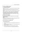
MIC-3660
User's Manual
Chapter 2 Hardware Installation
5
Copyright Notice
This document is copyrighted, 1998. All rights are reserved. The
original manufacturer reserves the right to make improvements to the
products described in this manual at any time without notice.
No part of this manual may be reproduced, copied, translated or
transmitted in any form or by any means without the prior written
permission of the original manufacturer. Information provided in this
manual is intended to be accurate and reliable. However, the original
manufacturer assumes no responsibility for its use, nor for any
infringements upon the rights of third parties which may result from
its use.
Acknowledgements
IBM and PC/AT are trademarks of International Business Machines
Corporation.
Intel and Pentium are trademarks of Intel Corporation.
Microsoft Windows® is a registered trademark of Microsoft Corp.
PICMG™, CompactPCI™, and the PICMG™ and CompactPCI™ logos
are trademarks of the PCI Industrial Computers Manufacturers Group.
NWay is a trademark of National Semiconductor Corporation.
All other product names or trademarks are properties of their
respective owners.
Part No. 2003366000
Printed in Taiwan
1st Edition
December 1998
Preface and Table of Contents
Packing List
Ensure that the following materials have been received, immediately
after opening the box containing your MIC-3660 card:
• 1 MIC-3660 Fast Ethernet card
• 1 CD-ROM disc containing device drivers
• 1 warranty certificate
• This user's manual
If any of these items are missing or damaged, contact your distributor
or sales representative immediately.
Technical Support and Sales Assistance
If you have a technical question, please visit Advantech's support
website, located at: http://support.advantech.com.tw
For more information about Advantech's products and sales service,
please visit our homepage located at: http://www.advantech.com.tw
MIC-3360 User's Manual
Contents
Copyright Notice ................................................................... i
Acknowledgements ............................................................... i
Packing List ............................................................................ ii
Contents ................................................................................. iii
Tables and Figures ................................................................ iv
Chapter 1: Introduction ............................................................... 1
1.1
1.2
1.3
1.4
Description .................................................................. 2
Features ....................................................................... 2
Specifications .............................................................. 3
Safety Precautions ...................................................... 4
Chapter 2: Hardware and Drivers Installation ........................... 5
2.1
2.2
2.3
2.4
2.5
Initial Inspection ........................................................ 6
MIC-3660 Connector Locations ............................... 7
Front Panel LED Indicators ..................................... 8
Card Installation ........................................................ 9
Drivers Installation .................................................. 10
Chapter 3: Wiring and Networks ............................................... 11
3.1
Typical Network Connections ................................. 12
3.1.1 Wiring ....................................................................... 12
3.1.2 RJ-45 pin assignment s .............................................. 13
Preface and Table of Contents
Tables and Figures
Figure 2-1: MIC-3660 connector locations ............................................ 7
Figure 2-2: MIC-3660 front panel LEDs .................................................. 8
Figure 3-1: Typical network topology .................................................. 12
Figure 3-2: RJ-45 plug ........................................................................... 12
Figure 3-3: Twisted pair connector ...................................................... 13
Table 2-1: MIC-3660 front panel LED indicators ....................................................................... 8
Table 3-1: MIC-3660 RJ-45 pin assignments ............................................................................ 13
MIC-3360 User's Manual
CHAPTER
1
Introduction
Chapter 1 Introduction
1
1.1
Description
The MIC-3660 is a 3U-size, high-performance Fast Ethernet module
for CompactPCI systems. This module complies with IEEE 802.3/
802.3u for 10Base-T and 100 Base-TX data rates, and CompactPCI
Specification 2.0 R 2.1.
The module uses an Intel 82558B Fast Ethernet controller with
integrated PHY. Its on-chip 3 KB receive/3 KB transmit FIFOs and
32-bit PCI scatter-gather bus mastering capability provide "glueless"
high speed data transfer at 100 Mbps with minimum Interframe
Spacing (IFS).
The MIC-3660 can be connected to 10 or 100 Mbps Ethernet network. It detects the speed of the network and switches to 10 or 100
Mbps operation automatically.
The MIC-3660 comes with drivers for a wide variety of networks and
operating systems. It is an excellent choice for operation in
standalone and harsh industrial environments.
1.2
Features
• CompactPCI Specification 2.0 R 2.1 compliant
• Conforms to IEEE 802.3/802.3u 10Base-T and 100Base-TX
• 32-bit PCI bus master interface
• High-speed operation (100 Mbps)
• NWayTM auto-negotiation capability detects operation speed (10 or
100 Mbps) and mode (half or full duplex)
• Plug & Play auto-configuration without setting jumpers or switches
• 3 KB transmit and 3 KB receive FIFOs
• NetWare, NDIS, ODI and Packet drivers included
• Three LEDs indicate link status, network activity and speed
2
MIC-3660 User's Manual
1.3
Specifications
• IEEE 802.3/802.3u 10Base-T and 100Base-TX compatible
• CompactPCI Specification 2.0 R 2.1 compliant
• Complies to PCI Bus Specification R 2.1
• IEEE 1101.10 compliant handle and front panel
• RJ-45 connector: The RJ-45 connector can use IEEE 802.3
10Base-T compliant Category 3, 4, or 5 cables. It can only use a
Category 5 UTP cable for 100 Mbps operation. Select a highquality brand of Category 5 cable from your local supplier. The
maximum length of the cable is 100 meters
• Controller chip: Intel 82558
• Driver support: NetWare 286/486, Microsoft LAN manager,
LANtastics 6.0, Banyan, IBM LANsupport Program, Windows 3.1/
95/98/NT
• Power consumption: +5 V @ 1.0 A (max.)
• Operating temperature: 0 ~ 60° C (32 ~ 140° F)
• Storage temperature: -20 ~ 70° C (-4 ~ 158° F)
• Dimensions: 160 mm x 100 mm (6.3" x 3.9") 1-slot (4TE) width
• Weight: 0.2 kg (0.44 lb)
• Emissions: CE mark to CISPR 11 Class A; FCC Class A
Chapter 1 Introduction
3
1.4 Safety Precautions
Follow these simple precautions to protect yourself from harm and
your system from damage.
1. To avoid electric shock, always disconnect the power from your
system chassis before you work on it. Don't touch any components
on the card or other cards while the system is on.
2. Disconnect power before making any configuration changes. The
sudden rush of power as you connect a jumper or install a card may
damage sensitive electronic components.
3. Always ground yourself to remove any static charge before you
touch your CPU card. Be particularly careful not to touch the chip
connectors. Modern integrated electronic devices, especially CPUs
and memory chips, are extremely sensitive to static electric
discharges and fields. Keep the card in its antistatic packaging
when it is not installed in the PC, and place it on a static dissipative
mat when you are working with it. Wear a grounding wrist strap
for continuous protection.
4
MIC-3660 User's Manual
CHAPTER
2
Hardware and Drivers
Installation
Chapter 2 Hardware Installation
5
2.1
Initial Inspection
We carefully inspected the MIC-3660 mechanically and electronically before we shipped it. It should be free of marks and scratches and
in perfect working order on receipt.
As you unpack the MIC-3660, check it for signs of shipping damage
(damaged box, scratches, dents, etc.). If it is damaged or fails to meet
specifications, notify our service department or your local sales
representative immediately. Also notify the carrier that was used to
ship the product to your location from our factory or distributor.
Retain the shipping carton and packing material for inspection by the
carrier. We will make arrangements to repair or replace the unit after
an inspection.
When you handle the MIC-3660, remove it from its protective
packaging by grasping the front metal panel. Keep the anti-vibration
packing. Whenever you remove the card from the PC, store it in this
package for protection.
Warning! Discharge your body’s static electric charge by
touching the back of the grounded chassis of the
system unit (metal) before handling the board. You
should avoid contact with materials that hold a static
charge such as plastic, vinyl and styrofoam. Handle
the board only by its edges to avoid static damage to
its integrated circuits. Avoid touching the exposed
circuit connectors.
6
MIC-3660 User's Manual
2.2
MIC-3660 Connector Locations
100 mm
J1: CompactPCI
bus connector
Boot ROM socket
(Default Vpp = +12 V,
open R25 and short
R26 to change to +5 V)
160 mm
CN1: RJ-45 10/100 Mbps
LAN connector
LINK LED ACT LED
100 Mbps
LED
Figure 2-1: MIC-3660 connector locations
Chapter 2 Hardware Installation
7
2.3
Front Panel LED Indicators
There are three diagnostic LEDs on the front panel. These LEDs show
the operating status of the MIC-3660.
LINK
ACT
100
Mbps
Figure 2-2: MIC-3660 front panel LEDs
Table 2-1: MIC-3660 front panel LED indicators
LED
Indicator
Meaning
LINK
On
The linking between the switch and
adapter is good
Off
The linking between the switch and
adapter is faulty
On
The MIC-3660 is sending or receiving
network data
Off
The MIC-3660 is not sending or
receiving network data
ACT
100Mbps On
Off
8
MIC-3660 User's Manual
Operating at 100 Mbps
Operating at 10 Mbps
2.4
Card Installation
The MIC-3660 is a PCI bus master card. It can be installed only in a
CompactPCI slot which supports a bus master card. Some processor
boards do not support bus master for each slot. Refer to the user's
manual of your processor board.
The CompactPCI connectors are firm and rigid and require careful
handling while plugging and unplugging. Improper installation of a
card can easily damage the backplane of the chassis.
The insert/eject handle of the MIC-3660 helps you to install and remove
the card easily and safely. Follow the procedure below to install the
MIC-3660 into a chassis:
To install a card:
1. Hold the MIC-3660 vertically. Be sure that the card is pointing in
the correct direction. The components of the card should be
pointing to the right-hand side.
2. Holding the handle, pull out the red portion in the middle of the
handle to unlock it.
Caution:
Keep your fingers away from the hinge to prevent
them from getting pinched.
3. Insert the card into the chassis by sliding the upper and lower
edges of the card into the card guides.
4. Push the card into the slot gently by sliding the card along the card
guides until the handle meets the rectangular holes of the cross
rails.
Note:
If the card is correctly positioned and has been slid
all the way into the chassis, the handle should match
the rectangular holes. If not, remove the card from
the card guide and repeat step 3 again. Do not try to
install a card by forcing it into the chassis.
5. Lift the handle up to push the card into place.
6. Secure the card by pushing in the red handle, and tighten the
screws on the front panel to lock it into place.
To remove a card:
1. Unscrew the two screws on the front panel. Pull out the red part to
unlock the handle.
2. Press the handle down to release the card from the backplane.
3. Slide the card out.
Chapter 2 Hardware Installation
9
2.5
Drivers Installation
The MIC-3660 supports PCI Plug and Play. The BIOS automatically
detects the MIC-3660 while booting, and assigns an IRQ level and I/O
address. No jumper and switch is required for user configuration.
The MIC-3660 uses an Intel 82558B Fast Ethernet controller chip. Thus
it is software compatible with Intel's EtherExpress™ PRO/100B LAN
adapter (except for the wake-up on LAN feature).
The drivers and installation instructions are located in the following
directories of the utility CD-ROM disc:
• \MIC3000\MIC3660\Dos: Drivers for DOS platforms
• \MIC3000\MIC3660\Info: Installation instructions
• \MIC3000\MIC3660\Ndis: Drivers for NDIS 2.x drivers and support
files
•
•
•
•
•
\MIC3000\MIC3660\Nt: Drivers for Windows NT
\MIC3000\MIC3660\Nwserver: Drivers for Novell NetWare
\MIC3000\MIC3660\Wfw: Drivers for Windows 3.11 for Workgroups
\MIC3000\MIC3660\Win95: Drivers for Windows 95
\MIC3000\MIC3660\Win98: Drivers for Windows 98
Please refer to the text files in \MIC3000\MIC3660\Info for detailed
information about installing the drivers.
10
Note:
Do not use the driver recommended by the Windows
95/NT Add New Hardware wizard. Choose the driver
from the utility CD-ROM disc. Assuming your CD-ROM
drive is D:, select "D:\MIC3000\MIC-3660\
net82557.inf" as the driver. Choose "Intel EtherExpress
PRO/100B PCI Adapter(TX)" when you are asked
to select hardware from the list.
Note:
Operating system vendors may post driver updates
on their web sites. Please visit the web sites of OS
vendors to download updated drivers.
MIC-3660 User's Manual
CHAPTER
3
Wiring and
Networks
Chapter 3 Wiring and Networks
11
3.1
Typical Network Connections
Before installing your Ethernet card, you should set aside some time
to plan your network. It is necessary to consider the number of
workstations and the physical distance between them. A typical
network layout is shown below:
Thick Coaxial Cable RG-11
Thin Coaxial Cable RG-18
Bridge
Bridge
Twisted pair
Server
Workstation
Workstation
Workstation
Figure 3-1: Typical network topology
3.1.1 Wiring
When connecting your network, you must ensure the correct wiring
and termination methods are employed.
The MIC-3660 accepts an RJ-45 connector, as shown below. To
connect the twisted pair Ethernet (TPE) cable to the adapter, orient
RJ-45 jack with the connector so the key is aligned with the slot. Then
gently push the connector into the receptacle until you hear or feel a
click.
8
1
8 7 6 5 4 3 2 1
Figure 3-2: RJ-45 plug
12
MIC-3660 User's Manual
Figure 3-3: Twisted pair connector
3.1.2 RJ-45 pin assignments
The RJ-45 media connector on your card or hub has specific leads that
correspond to each of the eight pins on the RJ-45 jack. This cable is
responsible for the transmission and reception of all data over the
network. Refer to the table and diagram below for the pin assignments.
Table 3-1: MIC-3660 RJ-45 pin assignments
Pin
Signal
Description
1
TD+
Transmit positive
2
TD-
Transmit negative
3
RD+
Receive positive
6
RD-
Receive negative
Chapter 3 Wiring and Networks
13
14
MIC-3660 User's Manual