1
OC297-1.qxp
03.6.9 4:24 PM
Page 1
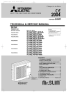
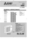
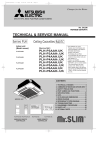
SPLIT-TYPE AIR CONDITIONERS
No.OC297
TECHNICAL & SERVICE MANUAL
Series PLA Ceiling Cassettes R410A
Indoor unit
[Model names]
[Service Ref.]
PLA-RP3AA.UK
PLA-RP4AA.UK
PLA-RP5AA.UK
PLA-RP6AA.UK
PLA-RP3AA
PLA-RP4AA
PLA-RP5AA
PLA-RP6AA
• Refer to the OCT04 as for control
relation.This manual does not cover
outdoor units.
When serving them, please refer to
the service manual No.OC294 and
this manual in a set.
CONTENTS
1. SAFETY PRECAUTION·······························2
2. PART NAMES AND FUNCTIONS ···············4
3. SPECIFICATIONS ········································7
4. DATA···························································11
5. OUTLINES AND DIMENSIONS ·················23
6. WIRING DIAGRAM ····································24
7. REFRIGERANT SYSTEM DIAGRAM···········25
8. TROUBLESHOOTING ·······························26
9. DISASSEMBLY PROCEDURE ··················37
10. PARTS LIST ···············································40
11. OPTIONAL PARTS·····································46
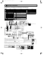
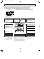
INDOOR UNIT
CHECK TEST RUN
MODEL SELECT
˚C
AMPM
AMPM
NOT AVAILABLE
ON/OFF
CENTRALLY CONTROLLED
TEMP
ON
1Hr.
OFF
˚C
CLOCK
CHECK
˚C
STAND BY
DEFROST
ERROR CODE
TEMP.
WIRELESS REMOTE
CONTROLLER
NOT AVAILABLE
FILTER
CHECK MODE
TEST RUN
FUNCTION
ON/OFF
WIRED REMOTE
CONTROLLER
OC297-1.qxp
1
03.6.9 4:24 PM
Page 2
SAFETY PRECAUTION
CAUTIONS RELATED TO NEW REFRIGERANT
<Cautions for units utilizing refrigerant R410A>
Use new refrigerant pipes.
Do not use refrigerant other than R410A.
In case of using the existing pipes for R22, be careful with
the followings.
· For RP4, 5 and 6, be sure to perform replacement operation before test run.
· Change flare nut to the one provided with this product.
Use a newly flared pipe.
· Avoid using thin pipes.
If other refrigerant (R22 etc.) is used, chlorine in refrigerant can cause deterioration of refrigerant oil etc.
Make sure that the inside and outside of refrigerant piping is clean and it has no contamination
such as sulfur hazardous for use, oxides, dirt,
shaving particles, etc.
In addition, use pipes with specified thickness.
Use a vacuum pump with a reverse flow check
valve.
Vacuum pump oil may flow back into refrigerant cycle and
that can cause deterioration of refrigerant oil etc.
Use the following tools specifically designed for
use with R410A refrigerant.
The following tools are necessary to use R410A refrigerant.
Tools (for R410A)
Gauge manifold
Flare tool
Charge hose
Size adjustment gauge
Vacuum pump adaptor
Gas leak detector
Torque wrench
Electronic refrigerant
charging scale
Contamination inside refrigerant piping can cause deterioration of refrigerant oil etc.
Store the piping to be used during installation
indoors and keep both ends of the piping sealed
until just before brazing. (Leave elbow joints, etc.
in their packaging.)
Keep the tools with care.
If dirt, dust or moisture enter into refrigerant cycle, that can
cause deterioration of refrigerant oil or malfunction of compressor.
If dirt, dust or moisture enter into refrigerant cycle, that can
cause deterioration of refrigerant oil or malfunction of compressor.
Use ester oil, ether oil or alkylbenzene oil (small
amount) as the refrigerant oil applied to flares
and flange connections.
If large amount of mineral oil enter, that can cause deterioration of refrigerant oil etc.
Charge refrigerant from liquid phase of gas
cylinder.
Do not use a charging cylinder.
If a charging cylinder is used, the composition of refrigerant will change and the efficiency will be lowered.
Ventilate the room if refrigerant leaks during
operation. If refrigerant comes into contact with
a flame, poisonous gases will be released.
If the refrigerant is charged from gas phase, composition
change may occur in refrigerant and the efficiency will be
lowered.
[1] Cautions for service
(1) Perform service after collecting the refrigerant left in unit completely.
(2) Do not release refrigerant in the air.
(3) After completing service, charge the cycle with specified amount of refrigerant.
(4) When performing service, install a filter drier simultaneously.
Be sure to use a filter drier for new refrigerant.
[2] Additional refrigerant charge
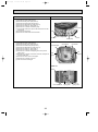
When charging directly from cylinder
· Check that cylinder for R410A on the market is syphon type.
· Charging should be performed with the cylinder of syphon stood vertically. (Refrigerant is charged from liquid phase.)
2
OC297-1.qxp
03.6.9 4:24 PM
Page 3
Unit
Gravimeter
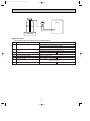
[3] Service tools
Use the below service tools as exclusive tools for R410A refrigerant.
No.
1
Specifications
Gauge manifold
·Only for R410A
·Use the existing fitting specifications. (UNF1/2)
·Use high-tension side pressure of 5.3MPa·G or over.
2
Charge hose
3
Electronic scale
4
Gas leak detector
·Use the detector for R134a, R407C or R410A.
5
Adaptor for reverse flow check
·Attach on vacuum pump.
6
Refrigerant charge base
7
Refrigerant cylinder
8
Refrigerant recovery equipment
·Only for R410A
·Use pressure performance of 5.09MPa·G or over.
·Only for R410A
Top of cylinder (Pink)
Cylinder with syphon
3
OC297-1.qxp
2
03.6.9 4:24 PM
Page 4
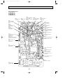
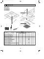
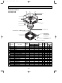
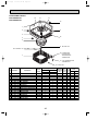
PART NAMES AND FUNCTIONS
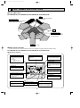
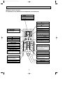
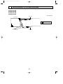
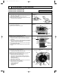
● Indoor (Main) Unit
PLA-RP3AA.UK, PLA-RP4AA.UK, PLA-RP5AA.UK, PLA-RP6AA.UK
Filter
Removes dust and pollutants
from intake air
Horizontal Air Outlet
Sets airflow of horizontal automatically
during cooling or dehumidifying.
Grille
Auto Air Swing Vane
Disperses airflow up and
down and adjusts the angle
of airflow direction.
Air Intake
Intakes air from room.
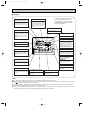
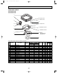
● Wired remote controller
On the controls are set, the same operation mode can be repeated by simply pressing the ON/OFF button.
PLA-RP3AA.UK, PLA-RP4AA.UK, PLA-RP5AA.UK, PLA-RP6AA.UK
● Operation buttons
TEMP. ADJUSTMENT button
This sets the room temperature. The
temperature setting can be performed
in 1: units
Setting range
Cooling 19: to 30:
Heating 17: to 28:
TIME SETTING button
FAN SPEED button
This sets the current time, start time
and stop time.
This sets the ventilation fan speed.
ON/OFF button
This switches between the operation
and stop modes each time it is pressed.
The lamp on this button lights during
operation.
TIMER button
1Hr.
CENTRALLY CONTROLLED
ON
This switches between continuous
operation and the timer operation.
OFF
˚C
CLOCK
CHECK
˚C
STAND BY
DEFROST
ERROR CODE
NOT AVAILABLE
TEMP.
FILTER
CHECK MODE
TEST RUN
FUNCTION
ON/OFF
AIR DIRECTION button
This adjusts the vertical angle of the
ventilation.
FILTER
OPERATION SWITCH button
Press this button to switch the cooling,
electronic dry (dehumidify), automatic
and heating modes.
CHECK TEST
PAR-20MAA
FILTER button
TIMER SET
This resets the filter service indication
display
LOUVER button
VENTILATION button
CHECK-TEST RUN button
This switch the horizontal fan motion
ON and OFF.
This sets the ventilation fan speed.
Only press this button to perform an
inspection check or test operation.
Do not use it for normal operation.
(Not available for this model.)
4
OC297-1.qxp
03.6.9 4:24 PM
Page 5
● Display
CENTRALLY
CONTROLLED display
This indicates when the unit is controlled by optional features such as
central control type remote controller.
In this display example on the bottom left, a condition where all display lamps light is shown for explanation purposes although this differs
from actual operation.
CLOCK display
The current time , start time and stop
time can be displayed in ten second
intervals by pressing the time switch
button. The start time or stop time is
always displayed during the timer
operation.
AIR DIRECTION display
TIMER display
This displays the air direction.
This indicates when the continuous
operation and time operation modes
are set.
It also display the time for the timer
operation at the same time as when
it is set.
AIR SPEED display
The selected fan speed is displayed.
ROOM TEMPERATURE
1Hr.
CENTRALLY CONTROLLED
OPERATION MODE display
This indicates the operation mode.
ON
OFF
˚C
CLOCK
CHECK
˚C
STAND BY
DEFROST
ERROR CODE
TEMP.
NOT AVAILABLE
FILTER
CHECK MODE
TEST RUN
FUNCTION
ON/OFF
display
The temperature of the suction air
is displayed during operation. The
display range is 8°C to 39°C. The
display flashes 8°C when the actual
temperature is less than 8°C and
flashes 39°C when the actual temperature is greater than 39°C.
FILTER
STANDBY display
The [STANDBY] symbol is only displayed from the time the heating
operation starts unit the heated air
begins to blow.
CHECK TEST
PAR-20MAA
TIMER SET
Operation lamp
This lamp lights during operation,
goes off when the unit stops and
flashes when a malfunction occurs.
CHECK MODE
TEST RUN
DEFROST display
display
This display lights in the check mode
or when a test operation is performed.
This indicates when the defrost operation is performed.
FILTER display
This lamp lights when the filter need
to be cleaned.
CHECK display
This indicates when a malfunction
has occurred in the unit which should
be checked.
SET TEMPERATURE display
POWER display
This displays the selected setting
temperature.
This lamp lights when electricity is
supplied to the unit.
Caution
● Only the Power display lights when the unit is stopped and power supplied to the unit.
● When the central control remote control unit, which is sold separately, is used the ON-OFF button, operation switch button
and
TEMP. adjustment button do not operate.
● “NOT AVAILABLE” is displayed when the Air speed button are pressed.This indicates that this room unit is not equipped
with the fan direction adjustment function and the louver function.
● When power is turned ON for the first time, it is normal that “H0” is displayed on the room temperature indication (For max.
2minutes). Please wait until this “H0” indication disappear then start the operation.
5
OC297-1.qxp
03.6.9 4:24 PM
Page 6
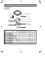
● Wireless remote controller
PLA-RP3AA.UK, PLA-RP4AA.UK, PLA-RP5AA.UK, PLA-RP6AA.UK
CHECK TEST RUN display
CHECK&TEST RUN display indicates that
the unit is being checked or test-run.
MODEL SELECT display
Blinks when model is selected.
display
Lights up while transmission to the indoor
unit is mode using switches.
display
SET TEMP. display indicates desired temperature set.
CLOCK display
display
Displays the current time.
OPERATION MODE display
Operation mode display indicates which operation mode is in effect.
TIMER display
CHECK TEST RUN
MODEL SELECT
˚C
AMPM
Displays when in timer operation or when
setting timer.
“
AMPM
NOT AVAILABLE
display
The vertical direction of air flow is indicated.
ON/OFF
“
TEMP
”“
” display
Displays the order of timer operation.
”“
” display
Displays whether timer is on or off.
display
button
FAN SPEED display indicates which fan
speed has been selected.
FAN
AUTO STOP
VANE
AUTO START
SET TEMPERATURE button sets any desired
room temperature.
ON/OFF button
The unit is turned ON and OFF alternately
each time the button is pressed.
MODE
CHECK LOUVER
h
FAN SPEED SELECT button
Used to change the fan speed.
MODE SELECT button
TEST RUN
SET
min
RESET
TIMER CONTROL buttons
AUTO STOP (OFF timer): when this switch
is set, the air conditioner will be automatically stopped at the preset time.
AUTO START (ON timer): when this switch
is set, the air conditioner will be automatically started at the preset time.
CLOCK
Used to switch the operation mode between
cooling, drying, blowing, heating and auto
mode.
h and min buttons
Buttons used to set the “hour and minute” of
the current time and timer settings.
w In case the outdoor unit is cool only type,
the heating mode is not available.
LOUVER button
CHECK-TEST RUN button
This switch the horizontal fan motion ON
and OFF.
Only press this button to perform an inspection check or test operation.
Do not use it for normal operation.
(Not available for this model.)
CLOCK button
VANE CONTROL button
RESET button
Used to change the air flow direction.
SET button
6
OC297-1.qxp
03.6.9 4:24 PM
3
Page 7
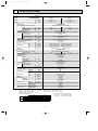
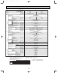
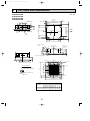
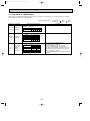
SPECIFICATIONS
Service Ref.
Item
Function
PLA-RP3AA.UK
Cooling
24,200
7,100 (3,300~8,100)
1.97
Btu/h
W
kW
Capacity
Total input
Indoor unit
Service Ref.
Outdoor unit
Refrigerant piping
NOTE:
PLA-RP3AA.UK
Power supply (phase, cycle,voltage)
Input
Running current
Starting current
External finish (Panel)
Heat exchanger
Fan (drive) o No.
Fan motor output
Fan
Airflow (Lo-Mi2-Mi1-Hi)
External static pressure
Booster heater
Operation control & Thermostat
Sound level (Lo-Mi2-Mi1-Hi)
Unit drain pipe I.D.
W
Dimensions
D
H
Weight
Single phase, 50Hz, 220-230-240V
0.16
0.16
0.79
0.79
1.0
1.0
Munsell 0.70Y 8.59/0.97
Plate fin coil
Turbo fan (direct) o1
0.070
15-16-18-20 (530-565-635-705)
0 (direct blow)
—
Remote controller & built-in
28-30-32-34
32 (1-1/4)
UNIT : 840 (33-1/16)
PANEL : 950 (37-3/8)
UNIT : 840 (33-1/16)
PANEL : 950 (37-3/8)
UNIT : 258 (10-1/2)
PANEL : 30 (1-3/16)
kW
A
A
kW
K / min (CFM)
Pa (mmAq)
kW
dB
mm (in.)
mm (in.)
mm (in.)
mm (in.)
kg (lbs.)
UNIT : 24 (53)
1. Rating conditions (ISO T1)
Cooling
Indoor : D.B. 27: (80˚F) W.B. 19: (66˚F)
Heating
Indoor : D.B. 20: (68˚F)
Refrigerant piping length (one way) : 5m (16ft.)
2. Guaranteed operating range
Upper limit
Lower limit
Upper limit
Heating
Lower limit
PANEL: 5 (11)
PUHZ-RP3VHA
Single phase, 50Hz, 220-230-240V
8.04
9.74
Munsell 3Y 7.8/1.1
Linear expansion valve
Hermetic
TNB220FMBH
1.6
Line start
HP switch, Discharge thermo.
Plate fin coil
Propeller (direct) o1
0.060
55 (1,940)
—
Reverse cycle
47
48
950 (37-3/8)
330+30 (13+1-3/16)
943 (37-1/8)
75 (165)
R410A
3.5 (7.7)
0.87 (NEO22)
9.52 (3/8)
15.88 (5/8)
Flared
Flared
Max. 30m
Max. 50m
Service Ref.
Power supply (phase, cycle, voltage)
Running current
A
External finish
Refrigerant control
Compressor
Model
Motor output
kW
Starter type
Protection devices
Heat exchanger
Fan (drive) o No.
Fan
Fan motor output
kW
Airflow
K/ min (CFM)
Crankcase heater
W
Defrost method
Cooling
dB
Sound level
Heating
dB
W
mm (in.)
Dimensions
D
mm (in.)
H
mm (in.)
Weight
kg (lbs.)
Refrigerant
Charge
kg (lbs.)
Oil (Model)
L
Liquid
mm (in.)
Pipe size O.D.
Gas
mm (in.)
Indoor side
Connection method
Outdoor side
Between the indoor & Height difference
outdoor units
Piping length
Cooling
Heating
27,300
8,000 (3,500~10,200)
2.34
Outdoor : D.B. 35: (95˚F) W.B. 24: (75˚F)
Outdoor : D.B. 7: (45˚F) W.B. 6: (43˚F)
Indoor
Outdoor
D.B. 35˚C, W.B. 22.5˚C D.B. 46˚C
D.B. 19˚C, W.B. 15˚C
D.B. -5˚C
D.B. 21˚C, W.B. 15˚C
D.B. 28˚C
D.B. -11˚C, W.B. -12˚C
D.B. 17˚C
7
3. Above data based on indicated voltage
Indoor unit
Single phase 230V 50Hz
Outdoor unit
Single phase 230V 50Hz
OC297-1.qxp
03.6.9 4:24 PM
Page 8
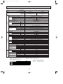
Service Ref.
Item
Function
Btu/h
W
kW
Capacity
Total input
PLA-RP4AA.UK
Cooling
34,100
10,000 (5,000~11,400)
3.03
Indoor unit
Service Ref.
Outdoor unit
Refrigerant piping
NOTE:
PLA-RP4AA.UK
Power supply (phase, cycle,voltage)
Input
Running current
Starting current
External finish (Panel)
Heat exchanger
Fan (drive) o No.
Fan motor output
Fan
Airflow (Lo-Mi2-Mi1-Hi)
External static pressure
Booster heater
Operation control & Thermostat
Sound level (Lo-Mi2-Mi1-Hi)
Unit drain pipe I.D.
W
Dimensions
D
H
Weight
Single phase, 50Hz, 220-230-240V
0.25
0.25
1.25
1.25
2.0
2.0
Munsell 0.70Y 8.59/0.97
Plate fin coil
Turbo fan (direct) o1
0.120
20-23-26-28 (705-810-920-990)
0 (direct blow)
—
Remote controller & built-in
33-36-39-41
32 (1-1/4)
UNIT : 840 (33-1/16) PANEL : 950 (37-3/8)
UNIT : 840 (33-1/16) PANEL : 950 (37-3/8)
UNIT : 298 (11-3/4) PANEL : 30 (1-3/16)
kW
A
A
kW
K / min (CFM)
Pa (mmAq)
kW
dB
mm (in.)
mm (in.)
mm (in.)
mm (in.)
UNIT : 30 (66)
kg (lbs.)
Service Ref.
Power supply (phase, cycle, voltage)
Running current
A
External finish
Refrigerant control
Compressor
Model
Motor output
kW
Starter type
Protection devices
Heat exchanger
Fan (drive) o No.
Fan
Fan motor output
kW
Airflow
K / min (CFM)
Crankcase heater
W
Defrost method
Cooling
dB
Sound level
Heating
dB
W
mm (in.)
Dimensions
D
mm (in.)
H
mm (in.)
Weight
kg (lbs.)
Refrigerant
Charge
kg (lbs.)
Oil (Model)
L
Liquid
mm (in.)
Pipe size O.D.
Gas
mm (in.)
Indoor side
Connection method
Outdoor side
Between the indoor & Height difference
outdoor units
Piping length
1. Rating conditions (ISO T1)
Cooling
Indoor : D.B. 27: (80˚F) W.B. 19: (66˚F)
Heating
Indoor : D.B. 20: (68˚F)
Refrigerant piping length (one way) : 5m (16ft.)
2. Guaranteed operating range
Upper limit
Lower limit
Upper limit
Heating
Lower limit
Cooling
Heating
38,200
11,200 (5,600~14,000)
3.39
Indoor
D.B. 35˚C, W.B. 22.5˚C
D.B. 19˚C, W.B. 15˚C
D.B. 28˚C
D.B. 17˚C
PANEL : 5 (11)
PUHZ-RP4VHA
Single phase, 50Hz, 220-230-240V
12.33
13.94
Munsell 3Y 7.8/1.1
Linear expansion valve
Hermetic
ANV33FDAMT
1.9
Line start
HP switch, LP switch, Discharge thermo.
Plate fin coil
Propeller (direct) o2
0.060+0.060
100 (3,530)
—
Reverse cycle
49
51
950 (37-3/8)
330+30 (13+1-3/16)
1,350 (53-1/8)
121 (267)
R410A
5.5 (12.1)
1.4 (MEL56)
9.52 (3/8)
15.88 (5/8)
Flared
Flared
Max. 30m
Max. 75m
Outdoor : D.B. 35: (95˚F)
Outdoor : D.B. 7: (45˚F)
Outdoor
D.B. 46˚C
D.B. -5˚C
D.B. 21˚C, W.B. 15˚C
D.B. -11˚C, W.B. -12˚C
8
W.B. 24: (75˚F)
W.B. 6: (43˚F)
3. Above data based on indicated voltage
Indoor unit
Single phase 230V 50Hz
Outdoor unit
Single phase 230V 50Hz
03.6.9 4:24 PM
Page 9
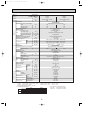
Service Ref.
Item
Function
Btu/h
W
kW
Capacity
Total input
PLA-RP5AA.UK
Indoor unit
Outdoor unit
NOTE:
PLA-RP5AA.UK
Power supply (phase, cycle,voltage)
Input
Running current
Starting current
External finish (Panel)
Heat exchanger
Fan (drive) o No.
Fan motor output
Fan
Airflow (Lo-Mi2-Mi1-Hi)
External static pressure
Booster heater
Operation control & Thermostat
Sound level (Lo-Mi2-Mi1-Hi)
Unit drain pipe I.D.
W
Dimensions
D
H
Weight
Single phase, 50Hz, 220-230-240V
0.33
0.33
1.64
1.64
2.0
2.0
Munsell 0.70Y 8.59/0.97
Plate fin coil
Turbo fan (direct) o1
0.120
22-25-28-30 (775-880-990-1,060)
0 (direct blow)
—
Remote controller & built-in
37-40-43-45
32 (1-1/4)
UNIT : 840 (33-1/16) PANEL : 950 (37-3/8)
UNIT : 840 (33-1/16) PANEL : 950 (37-3/8)
UNIT : 298 (11-3/4) PANEL : 30 (1-3/16)
kW
A
A
kW
K / min (CFM)
Pa (mmAq)
kW
dB
mm (in.)
mm (in.)
mm (in.)
mm (in.)
UNIT : 32 (71)
kg (lbs.)
Service Ref.
Power supply (phase, cycle, voltage)
Running current
A
External finish
Refrigerant control
Compressor
Model
Motor output
kW
Starter type
Protection devices
Heat exchanger
Fan (drive) o No.
Fan
Fan motor output
kW
K / min (CFM)
Airflow
Crankcase heater
W
Defrost method
Cooling
dB
Sound level
Heating
dB
W
mm (in.)
Dimensions
D
mm (in.)
H
mm (in.)
Weight
kg (lbs.)
Refrigerant
Charge
kg (lbs.)
Oil (Model)
L
Liquid
mm (in.)
Pipe size O.D.
Gas
mm (in.)
Indoor side
Connection method
Outdoor side
Between the indoor & Height difference
outdoor units
Piping length
1. Rating conditions (ISO T1)
Cooling : Indoor: D.B. 27: (80˚F) W.B. 19: (66˚F)
Heating : Indoor: D.B. 20: (68˚F)
Refrigerant piping length (one way) : 5m (16ft.)
2. Guaranteed operating range
Upper limit
Lower limit
Upper limit
Heating
Lower limit
Cooling
Heating
47,800
14,000 (6,000~16,000)
4.27
Cooling
42,700
12,500 (6,000~14,000)
3.89
Service Ref.
Refrigerant piping
OC297-1.qxp
Indoor
D.B. 35:, W.B. 22.5:
D.B. 19 :, W.B. 15:
D.B. 28:
D.B. 17:
PANEL : 5 (11)
PUHZ-RP5VHA
Single phase, 50Hz, 220-230-240V
15.80
17.50
Munsell 3Y 7.8/1.1
Linear expansion valve
Hermetic
ANV33FDAMT
2.4
Line start
HP switch, LP switch, Discharge thermo.
Plate fin coil
Propeller (direct) o2
0.060+0.060
100 (3,530)
—
Reverse cycle
50
52
950 (37-3/8)
330+30 (13+1-3/16)
1,350 (53-1/8)
121 (267)
R410A
5.5 (12.1)
1.4 (MEL56)
9.52 (3/8)
15.88 (5/8)
Flared
Flared
Max. 30m
Max. 75m
Outdoor: D.B. 35: (95˚F)
Outdoor: D.B. 7: (45˚F)
Outdoor
D.B. 46:
D.B. -5:
D.B. 21:, W.B. 15:
D.B. -11:, W.B. -12:
9
W.B. 24: (75˚F)
W.B. 6: (43˚F)
3. Above data based on indicated voltage
Indoor unit
Single phase 230V 50Hz
Outdoor unit
Single phase 230V 50Hz
OC297-1.qxp
03.6.9 4:24 PM
Page 10
Service Ref.
Item
Function
Btu/h
W
kW
Capacity
Total input
PLA-RP6AA.UK
Cooling
47,800
14,000 (6,200~15,300)
4.99
Indoor unit
Service Ref.
Outdoor unit
Refrigerant piping
NOTE:
PLA-RP6AA.UK
Power supply (phase, cycle,voltage)
Input
Running current
Starting current
External finish (Panel)
Heat exchanger
Fan (drive) o No.
Fan motor output
Fan
Airflow (Lo-Mi2-Mi1-Hi)
External static pressure
Booster heater
Operation control & Thermostat
Sound level (Lo-Mi2-Mi1-Hi)
Unit drain pipe I.D.
W
Dimensions
D
H
Weight
Single phase, 50Hz, 220-230-240V
0.33
0.33
1.64
1.64
2.0
2.0
Munsell 0.70Y 8.59/0.97
Plate fin coil
Turbo fan (direct) o1
0.120
22-25-28-30 (775-880-990-1,060)
0 (direct blow)
—
Remote controller & built-in
37-40-43-45
32 (1-1/4)
UNIT : 840 (33-1/16) PANEL : 950 (37-3/8)
UNIT : 840 (33-1/16) PANEL : 950 (37-3/8)
UNIT : 298 (11-3/4) PANEL : 30 (1-3/16)
kW
A
A
kW
K / min (CFM)
Pa (mmAq)
kW
dB
mm (in.)
mm (in.)
mm (in.)
mm (in.)
UNIT : 32 (71)
kg (lbs.)
Service Ref.
Power supply (phase, cycle, voltage)
Running current
A
External finish
Refrigerant control
Compressor
Model
Motor output
kW
Starter type
Protection devices
Heat exchanger
Fan (drive) o No.
Fan
Fan motor output
kW
K / min (CFM)
Airflow
Crankcase heater
W
Defrost method
Cooling
dB
Sound level
Heating
dB
W
mm (in.)
Dimensions
D
mm (in.)
H
mm (in.)
Weight
kg (lbs.)
Refrigerant
Charge
kg (lbs.)
Oil (Model)
L
Liquid
mm (in.)
Pipe size O.D.
Gas
mm (in.)
Indoor side
Connection method
Outdoor side
Between the indoor & Height difference
outdoor units
Piping length
1. Rating conditions (ISO T1)
Cooling : Indoor: D.B. 27: (80˚F) W.B. 19: (66˚F)
Heating : Indoor: D.B. 20: (68˚F)
Refrigerant piping length (one way) : 5m (16ft.)
2. Guaranteed operating range
Upper limit
Lower limit
Upper limit
Heating
Lower limit
Cooling
Heating
54,600
16,000 (6,200~18,000)
4.91
Indoor
D.B. 35:, W.B. 22.5:
D.B. 19 :, W.B. 15:
D.B. 28:
D.B. 17:
PANEL : 5 (11)
PUHZ-RP6VHA
Single phase, 50Hz, 220-230-240V
20.73
20.37
Munsell 3Y 7.8/1.1
Linear expansion valve
Hermetic
ANV33FDAMT
2.9
Line start
HP switch, LP switch, Discharge thermo.
Plate fin coil
Propeller (direct) o2
0.060+0.060
100 (3,530)
—
Reverse cycle
50
52
950 (37-3/8)
330+30 (13+1-3/16)
1,350 (53-1/8)
121 (267)
R410A
5.5 (12.1)
1.4 (MEL56)
9.52 (3/8)
15.88 (5/8)
Flared
Flared
Max. 30m
Max. 75m
Outdoor: D.B. 35: (95˚F)
Outdoor: D.B. 7: (45˚F)
Outdoor
D.B. 46:
D.B. -5 :
D.B. 21 :, W.B. 15:
D.B. -11:, W.B. -12:
10
W.B. 24: (75˚F)
W.B. 6: (43˚F)
3. Above data based on indicated voltage
Indoor unit
Single phase 230V 50Hz
Outdoor unit
Single phase 230V 50Hz
OC297-1.qxp
03.6.9 4:24 PM
4
Page 11
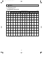
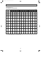
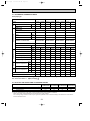
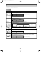
DATA
4-1. PERFORMANCE DATA
4-1-1. COOLING CAPACITY (1)
PLA-RP3AA.UK / PUHZ-RP3VHA
(230V)
Indoor Indoor
intake air intake air
D.B.(˚C) W.B.(˚C)
16
20
18
20
20
20
16
22
18
22
20
22
16
24
18
24
20
24
22
24
16
26
18
26
20
26
22
26
16
27
18
27
20
27
22
27
16
28
18
28
20
28
22
28
16
30
18
30
20
30
22
30
16
32
18
32
20
32
22
32
16
34
18
34
20
34
22
34
NOTE:
20
CA
7,029
7,526
8,094
7,029
7,526
8,094
7,029
7,526
8,094
8,627
7,029
7,526
8,094
8,627
7,029
7,526
8,094
8,627
7,029
7,526
8,094
8,627
7,029
7,526
8,094
8,627
7,029
7,526
8,094
8,627
7,029
7,526
8,094
8,627
SHC
4,499
3,914
3,238
5,061
4,516
3,885
5,623
5,118
4,533
3,796
6,186
5,720
5,180
4,486
6,467
6,021
5,504
4,831
6,748
6,322
5,828
5,176
7,029
6,924
6,475
5,866
7,029
7,526
7,123
6,556
7,029
7,526
7,770
7,246
CA: Capacity (W)
P.C.: Power consumption (kW)
SHF
0.64
0.52
0.40
0.72
0.60
0.48
0.80
0.68
0.56
0.44
0.88
0.76
0.64
0.52
0.92
0.80
0.68
0.56
0.96
0.84
0.72
0.60
1.00
0.92
0.80
0.68
1.00
1.00
0.88
0.76
1.00
1.00
0.96
0.84
P.C.
1.58
1.61
1.65
1.58
1.61
1.65
1.58
1.61
1.65
1.69
1.58
1.61
1.65
1.69
1.58
1.61
1.65
1.69
1.58
1.61
1.65
1.69
1.58
1.61
1.65
1.69
1.58
1.61
1.65
1.69
1.58
1.61
1.65
1.69
Outdoor intale air D.B.(˚C)
25
CA
SHC
SHF
P.C.
1.66
0.64
4,362
6,816
1.69
0.52
3,803
7,313
1.73
0.40
3,167
7,917
1.66
0.72
4,908
6,816
1.69
0.60
4,388
7,313
1.73
0.48
3,800
7,917
1.66
0.80
5,453
6,816
1.69
0.68
4,973
7,313
1.73
0.56
4,433
7,917
1.79
0.44
3,718
8,449
1.66
0.88
5,998
6,816
1.69
0.76
5,558
7,313
1.73
0.64
5,067
7,917
1.79
0.52
4,393
8,449
1.66
0.92
6,271
6,816
1.69
0.80
5,850
7,313
1.73
0.68
5,383
7,917
1.79
0.56
4,731
8,449
1.66
0.96
6,543
6,816
1.69
0.84
6,143
7,313
1.73
0.72
5,700
7,917
1.79
0.60
5,069
8,449
1.66
1.00
6,816
6,816
1.69
0.92
6,728
7,313
1.73
0.80
6,333
7,917
1.79
0.68
5,745
8,449
1.66
1.00
6,816
6,816
1.69
1.00
7,313
7,313
1.73
0.88
6,967
7,917
1.79
0.76
6,421
8,449
1.66
1.00
6,816
6,816
1.69
1.00
7,313
7,313
1.73
0.96
7,600
7,917
1.79
0.84
7,097
8,449
SHC: Sensible heat capacity (W)
SHF: Sensible heat factor
11
30
CA
6,603
7,065
7,704
6,603
7,065
7,704
6,603
7,065
7,704
8,236
6,603
7,065
7,704
8,236
6,603
7,065
7,704
8,236
6,603
7,065
7,704
8,236
6,603
7,065
7,704
8,236
6,603
7,065
7,704
8,236
6,603
7,065
7,704
8,236
SHC
4,226
3,674
3,081
4,754
4,239
3,698
5,282
4,804
4,314
3,624
5,811
5,369
4,930
4,283
6,075
5,652
5,238
4,612
6,339
5,934
5,547
4,942
6,603
6,499
6,163
5,600
6,603
7,065
6,779
6,259
6,603
7,065
7,395
6,918
SHF
0.64
0.52
0.40
0.72
0.60
0.48
0.80
0.68
0.56
0.44
0.88
0.76
0.64
0.52
0.92
0.80
0.68
0.56
0.96
0.84
0.72
0.60
1.00
0.92
0.80
0.68
1.00
1.00
0.88
0.76
1.00
1.00
0.96
0.84
P.C.
1.76
1.81
1.85
1.76
1.81
1.85
1.76
1.81
1.85
1.91
1.76
1.81
1.85
1.91
1.76
1.81
1.85
1.91
1.76
1.81
1.85
1.91
1.76
1.81
1.85
1.91
1.76
1.81
1.85
1.91
1.76
1.81
1.85
1.91
OC297-1.qxp
03.6.9 4:24 PM
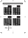
Page 12
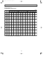
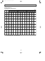
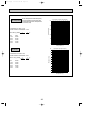
COOLING CAPACITY (2)
PLA-RP3AA.UK / PUHZ-RP3VHA
(230V)
Indoor Indoor
intake air intake air
D.B.(˚C) W.B.(˚C)
16
20
18
20
20
20
16
22
18
22
20
22
16
24
18
24
20
24
22
24
16
26
18
26
20
26
22
26
16
27
18
27
20
27
22
27
16
28
18
28
20
28
22
28
16
30
18
30
20
30
22
30
16
32
18
32
20
32
22
32
16
34
18
34
20
34
22
34
NOTE:
35
CA
6,319
6,816
7,384
6,319
6,816
7,384
6,319
6,816
7,384
7,952
6,319
6,816
7,384
7,952
6,319
6,816
7,384
7,952
6,319
6,816
7,384
7,952
6,319
6,816
7,384
7,952
6,319
6,816
7,384
7,952
6,319
6,816
7,384
7,952
SHC
4,044
3,544
2,954
4,550
4,090
3,544
5,055
4,635
4,135
3,499
5,561
5,180
4,726
4,135
5,813
5,453
5,021
4,453
6,066
5,725
5,316
4,771
6,319
6,271
5,907
5,407
6,319
6,816
6,498
6,044
6,319
6,816
7,089
6,680
CA: Capacity (W)
P.C.: Power consumption (kW)
SHF
0.64
0.52
0.40
0.72
0.60
0.48
0.80
0.68
0.56
0.44
0.88
0.76
0.64
0.52
0.92
0.80
0.68
0.56
0.96
0.84
0.72
0.60
1.00
0.92
0.80
0.68
1.00
1.00
0.88
0.76
1.00
1.00
0.96
0.84
P.C.
1.89
1.94
1.99
1.89
1.94
1.99
1.89
1.94
1.99
2.03
1.89
1.94
1.99
2.03
1.89
1.94
1.99
2.03
1.89
1.94
1.99
2.03
1.89
1.94
1.99
2.03
1.89
1.94
1.99
2.03
1.89
1.94
1.99
2.03
Outdoor intale air D.B.(˚C)
40
CA
SHC
SHF
P.C.
2.03
0.64
3,862
6,035
2.09
0.52
3,434
6,603
2.13
0.40
2,840
7,100
2.03
0.72
4,345
6,035
2.09
0.60
3,962
6,603
2.13
0.48
3,408
7,100
2.03
0.80
4,828
6,035
2.09
0.68
4,490
6,603
2.13
0.56
3,976
7,100
2.19
0.44
3,374
7,668
2.03
0.88
5,311
6,035
2.09
0.76
5,018
6,603
2.13
0.64
4,544
7,100
2.19
0.52
3,987
7,668
2.03
0.92
5,552
6,035
2.09
0.80
5,282
6,603
2.13
0.68
4,828
7,100
2.19
0.56
4,294
7,668
2.03
0.96
5,794
6,035
2.09
0.84
5,547
6,603
2.13
0.72
5,112
7,100
2.19
0.60
4,601
7,668
2.03
1.00
6,035
6,035
2.09
0.92
6,075
6,603
2.13
0.80
5,680
7,100
2.19
0.68
5,214
7,668
2.03
1.00
6,035
6,035
2.09
1.00
6,603
6,603
2.13
0.88
6,248
7,100
2.19
0.76
5,828
7,668
2.03
1.00
6,035
6,035
2.09
1.00
6,603
6,603
2.13
0.96
6,816
7,100
2.19
0.84
6,441
7,668
SHC: Sensible heat capacity (W)
SHF: Sensible heat factor
12
45
CA
5,751
6,177
6,674
5,751
6,177
6,674
5,751
6,177
6,674
7,242
5,751
6,177
6,674
7,242
5,751
6,177
6,674
7,242
5,751
6,177
6,674
7,242
5,751
6,177
6,674
7,242
5,751
6,177
6,674
7,242
5,751
6,177
6,674
7,242
SHC
3,681
3,212
2,670
4,141
3,706
3,204
4,601
4,200
3,737
3,186
5,061
4,695
4,271
3,766
5,291
4,942
4,538
4,056
5,521
5,189
4,805
4,345
5,751
5,683
5,339
4,925
5,751
6,177
5,873
5,504
5,751
6,177
6,407
6,083
SHF
0.64
0.52
0.40
0.72
0.60
0.48
0.80
0.68
0.56
0.44
0.88
0.76
0.64
0.52
0.92
0.80
0.68
0.56
0.96
0.84
0.72
0.60
1.00
0.92
0.80
0.68
1.00
1.00
0.88
0.76
1.00
1.00
0.96
0.84
P.C.
2.20
2.25
2.29
2.20
2.25
2.29
2.20
2.25
2.29
2.32
2.20
2.25
2.29
2.32
2.20
2.25
2.29
2.32
2.20
2.25
2.29
2.32
2.20
2.25
2.29
2.32
2.20
2.25
2.29
2.32
2.20
2.25
2.29
2.32
OC297-1.qxp
03.6.9 4:24 PM
Page 13
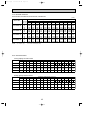
COOLING CAPACITY (3)
PLA-RP4AA.UK / PUHZ-RP4VHA
(230V)
Indoor Indoor
intake air intake air
D.B.(˚C) W.B.(˚C) CA
9,900
16
20
10,600
18
20
11,400
20
20
9,900
16
22
10,600
18
22
11,400
20
22
9,900
16
24
10,600
18
24
11,400
20
24
12,150
22
24
9,900
16
26
10,600
18
26
11,400
20
26
12,150
22
26
9,900
16
27
10,600
18
27
11,400
20
27
12,150
22
27
9,900
16
28
10,600
18
28
11,400
20
28
12,150
22
28
9,900
16
30
10,600
18
30
11,400
20
30
12,150
22
30
9,900
16
32
10,600
18
32
11,400
20
32
12,150
22
32
9,900
16
34
10,600
18
34
11,400
20
34
12,150
22
34
NOTE:
20
SHC
6,435
5,618
4,674
7,227
6,466
5,586
8,019
7,314
6,498
5,468
8,811
8,162
7,410
6,440
9,207
8,586
7,866
6,926
9,603
9,010
8,322
7,412
9,900
9,858
9,234
8,384
9,900
10,600
10,146
9,356
9,900
10,600
11,058
10,328
CA: Capacity (W)
P.C.: Power consumption (kW)
SHF
0.65
0.53
0.41
0.73
0.61
0.49
0.81
0.69
0.57
0.45
0.89
0.77
0.65
0.53
0.93
0.81
0.69
0.57
0.97
0.85
0.73
0.61
1.00
0.93
0.81
0.69
1.00
1.00
0.89
0.77
1.00
1.00
0.97
0.85
P.C.
2.42
2.47
2.55
2.42
2.47
2.55
2.42
2.47
2.55
2.61
2.42
2.47
2.55
2.61
2.42
2.47
2.55
2.61
2.42
2.47
2.55
2.61
2.42
2.47
2.55
2.61
2.42
2.47
2.55
2.61
2.42
2.47
2.55
2.61
Outdoor intale air D.B.(˚C)
25
CA
SHC
SHF
P.C.
2.56
0.65
6,240
9,600
2.61
0.53
10,300 5,459
2.67
0.41
11,150 4,572
2.56
0.73
7,008
9,600
2.61
0.61
10,300 6,283
2.67
0.49
11,150 5,464
2.56
0.81
7,776
9,600
2.61
0.69
10,300 7,107
2.67
0.57
11,150 6,356
2.76
0.45
11,900 5,355
2.56
0.89
8,544
9,600
2.61
0.77
10,300 7,931
2.67
0.65
11,150 7,248
2.76
0.53
11,900 6,307
2.56
0.93
8,928
9,600
2.61
0.81
10,300 8,343
2.67
0.69
11,150 7,694
2.76
0.57
11,900 6,783
2.56
0.97
9,312
9,600
2.61
0.85
10,300 8,755
2.67
0.73
11,150 8,140
2.76
0.61
11,900 7,259
2.56
1.00
9,600
9,600
2.61
0.93
10,300 9,579
2.67
0.81
11,150 9,032
2.76
0.69
11,900 8,211
2.56
1.00
9,600
9,600
2.61
1.00
10,300 10,300
2.67
0.89
11,150 9,924
2.76
0.77
11,900 9,163
2.56
1.00
9,600
9,600
2.61
1.00
10,300 10,300
2.67
0.97
11,150 10,816
2.76
0.85
11,900 10,115
SHC: Sensible heat capacity (W)
SHF: Sensible heat factor
13
CA
9,300
9,950
10,850
9,300
9,950
10,850
9,300
9,950
10,850
11,600
9,300
9,950
10,850
11,600
9,300
9,950
10,850
11,600
9,300
9,950
10,850
11,600
9,300
9,950
10,850
11,600
9,300
9,950
10,850
11,600
9,300
9,950
10,850
11,600
30
SHC
6,045
5,274
4,449
6,789
6,070
5,317
7,533
6,866
6,185
5,220
8,277
7,662
7,053
6,148
8,649
8,060
7,487
6,612
9,021
8,458
7,921
7,076
9,300
9,254
8,789
8,004
9,300
9,950
9,657
8,932
9,300
9,950
10,525
9,860
SHF
0.65
0.53
0.41
0.73
0.61
0.49
0.81
0.69
0.57
0.45
0.89
0.77
0.65
0.53
0.93
0.81
0.69
0.57
0.97
0.85
0.73
0.61
1.00
0.93
0.81
0.69
1.00
1.00
0.89
0.77
1.00
1.00
0.97
0.85
P.C.
2.71
2.79
2.85
2.71
2.79
2.85
2.71
2.79
2.85
2.94
2.71
2.79
2.85
2.94
2.71
2.79
2.85
2.94
2.71
2.79
2.85
2.94
2.71
2.79
2.85
2.94
2.71
2.79
2.85
2.94
2.71
2.79
2.85
2.94
OC297-1.qxp
03.6.9 4:24 PM
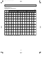
Page 14
COOLING CAPACITY (4)
PLA-RP4AA.UK / PUHZ-RP4VHA
(230V)
Indoor Indoor
intake air intake air
D.B.(˚C) W.B.(˚C) CA
8,900
16
20
9,600
18
20
10,400
20
20
8,900
16
22
9,600
18
22
10,400
20
22
8,900
16
24
9,600
18
24
10,400
20
24
11,200
22
24
8,900
16
26
9,600
18
26
10,400
20
26
11,200
22
26
8,900
16
27
9,600
18
27
10,400
20
27
11,200
22
27
8,900
16
28
9,600
18
28
10,400
20
28
11,200
22
28
8,900
16
30
9,600
18
30
10,400
20
30
11,200
22
30
8,900
16
32
9,600
18
32
10,400
20
32
11,200
22
32
8,900
16
34
9,600
18
34
10,400
20
34
11,200
22
34
NOTE:
35
SHC
5,785
5,088
4,264
6,497
5,856
5,096
7,209
6,624
5,928
5,040
7,921
7,392
6,760
5,936
8,277
7,776
7,176
6,384
8,633
8,160
7,592
6,832
8,900
8,928
8,424
7,728
8,900
9,600
9,256
8,624
8,900
9,600
10,088
9,520
CA: Capacity (W)
P.C.: Power consumption (kW)
SHF
0.65
0.53
0.41
0.73
0.61
0.49
0.81
0.69
0.57
0.45
0.89
0.77
0.65
0.53
0.93
0.81
0.69
0.57
0.97
0.85
0.73
0.61
1.00
0.93
0.81
0.69
1.00
1.00
0.89
0.77
1.00
1.00
0.97
0.85
P.C.
2.91
2.98
3.06
2.91
2.98
3.06
2.91
2.98
3.06
3.12
2.91
2.98
3.06
3.12
2.91
2.98
3.06
3.12
2.91
2.98
3.06
3.12
2.91
2.98
3.06
3.12
2.91
2.98
3.06
3.12
2.91
2.98
3.06
3.12
Outdoor intale air D.B.(˚C)
40
CA
SHC
SHF
P.C.
3.12
0.65
5,525
8,500
3.21
0.53
4,929
9,300
3.27
0.41
10,000 4,100
3.12
0.73
6,205
8,500
3.21
0.61
5,673
9,300
3.27
0.49
10,000 4,900
3.12
0.81
6,885
8,500
3.21
0.69
6,417
9,300
3.27
0.57
10,000 5,700
3.36
0.45
10,800 4,860
3.12
0.89
7,565
8,500
3.21
0.77
7,161
9,300
3.27
0.65
10,000 6,500
3.36
0.53
10,800 5,724
3.12
0.93
7,905
8,500
3.21
0.81
7,533
9,300
3.27
0.69
10,000 6,900
3.36
0.57
10,800 6,156
3.12
0.97
8,245
8,500
3.21
0.85
7,905
9,300
3.27
0.73
10,000 7,300
3.36
0.61
10,800 6,588
3.12
1.00
8,500
8,500
3.21
0.93
8,649
9,300
3.27
0.81
10,000 8,100
3.36
0.69
10,800 7,452
3.12
1.00
8,500
8,500
3.21
1.00
9,300
9,300
3.27
0.89
10,000 8,900
3.36
0.77
10,800 8,316
3.12
1.00
8,500
8,500
3.21
1.00
9,300
9,300
3.27
0.97
10,000 9,700
3.36
0.85
10,800 9,180
SHC: Sensible heat capacity (W)
SHF: Sensible heat factor
14
45
CA
8,100
8,700
9,400
8,100
8,700
9,400
8,100
8,700
9,400
10,200
8,100
8,700
9,400
10,200
8,100
8,700
9,400
10,200
8,100
8,700
9,400
10,200
8,100
8,700
9,400
10,200
8,100
8,700
9,400
10,200
8,100
8,700
9,400
10,200
SHC
5,265
4,611
3,854
5,913
5,307
4,606
6,561
6,003
5,358
4,590
7,209
6,699
6,110
5,406
7,533
7,047
6,486
5,814
7,857
7,395
6,862
6,222
8,100
8,091
7,614
7,038
8,100
8,700
8,366
7,854
8,100
8,700
9,118
8,670
SHF
0.65
0.53
0.41
0.73
0.61
0.49
0.81
0.69
0.57
0.45
0.89
0.77
0.65
0.53
0.93
0.81
0.69
0.57
0.97
0.85
0.73
0.61
1.00
0.93
0.81
0.69
1.00
1.00
0.89
0.77
1.00
1.00
0.97
0.85
P.C.
3.38
3.45
3.51
3.38
3.45
3.51
3.38
3.45
3.51
3.58
3.38
3.45
3.51
3.58
3.38
3.45
3.51
3.58
3.38
3.45
3.51
3.58
3.38
3.45
3.51
3.58
3.38
3.45
3.51
3.58
3.38
3.45
3.51
3.58
OC297-1.qxp
03.6.9 4:24 PM
Page 15
COOLING CAPACITY (5)
PLA-RP5AA.UK / PUHZ-RP5VHA
(230V)
Indoor Indoor
intake air intake air
D.B.(˚C) W.B.(˚C) CA
12,375
16
20
13,250
18
20
14,250
20
20
12,375
16
22
13,250
18
22
14,250
20
22
12,375
16
24
13,250
18
24
14,250
20
24
15,188
22
24
12,375
16
26
13,250
18
26
14,250
20
26
15,188
22
26
12,375
16
27
13,250
18
27
14,250
20
27
15,188
22
27
12,375
16
28
13,250
18
28
14,250
20
28
15,188
22
28
12,375
16
30
13,250
18
30
14,250
20
30
15,188
22
30
12,375
16
32
13,250
18
32
14,250
20
32
15,188
22
32
12,375
16
34
13,250
18
34
14,250
20
34
15,188
22
34
NOTE:
20
SHC
7,920
6,890
5,700
8,910
7,950
6,840
9,900
9,010
7,980
6,683
10,890
10,070
9,120
7,898
11,385
10,600
9,690
8,505
11,880
11,130
10,260
9,113
12,375
12,190
11,400
10,328
12,375
13,250
12,540
11,543
12,375
13,250
13,680
12,758
CA: Capacity (W)
P.C.: Power consumption (kW)
SHF
0.64
0.52
0.40
0.72
0.60
0.48
0.80
0.68
0.56
0.44
0.88
0.76
0.64
0.52
0.92
0.80
0.68
0.56
0.96
0.84
0.72
0.60
1.00
0.92
0.80
0.68
1.00
1.00
0.88
0.76
1.00
1.00
0.96
0.84
P.C.
3.11
3.17
3.27
3.11
3.17
3.27
3.11
3.17
3.27
3.35
3.11
3.17
3.27
3.35
3.11
3.17
3.27
3.35
3.11
3.17
3.27
3.35
3.11
3.17
3.27
3.35
3.11
3.17
3.27
3.35
3.11
3.17
3.27
3.35
Outdoor intale air D.B.(˚C)
25
CA
SHC
SHF
P.C.
3.29
0.64
12,000 7,680
3.35
0.52
12,875 6,695
3.42
0.40
13,938 5,575
3.29
0.72
12,000 8,640
3.35
0.60
12,875 7,725
3.42
0.48
13,938 6,690
3.29
0.80
12,000 9,600
3.35
0.68
12,875 8,755
3.42
0.56
13,938 7,805
3.54
0.44
14,875 6,545
3.29
0.88
12,000 10,560
3.35
0.76
12,875 9,785
3.42
0.64
13,938 8,920
3.54
0.52
14,875 7,735
3.29
0.92
12,000 11,040
3.35
0.80
12,875 10,300
3.42
0.68
13,938 9,478
3.54
0.56
14,875 8,330
3.29
0.96
12,000 11,520
3.35
0.84
12,875 10,815
3.42
0.72
13,938 10,035
3.54
0.60
14,875 8,925
3.29
1.00
12,000 12,000
3.35
0.92
12,875 11,845
3.42
0.80
13,938 11,150
3.54
0.68
14,875 10,115
3.29
1.00
12,000 12,000
3.35
1.00
12,875 12,875
3.42
0.88
13,938 12,265
3.54
0.76
14,875 11,305
3.29
1.00
12,000 12,000
3.35
1.00
12,875 12,875
3.42
0.96
13,938 13,380
3.54
0.84
14,875 12,495
SHC: Sensible heat capacity (W)
SHF: Sensible heat factor
15
CA
11,625
12,438
13,563
11,625
12,438
13,563
11,625
12,438
13,563
14,500
11,625
12,438
13,563
14,500
11,625
12,438
13,563
14,500
11,625
12,438
13,563
14,500
11,625
12,438
13,563
14,500
11,625
12,438
13,563
14,500
11,625
12,438
13,563
14,500
30
SHC
7,440
6,468
5,425
8,370
7,463
6,510
9,300
8,458
7,595
6,380
10,230
9,453
8,680
7,540
10,695
9,950
9,223
8,120
11,160
10,448
9,765
8,700
11,625
11,443
10,850
9,860
11,625
12,438
11,935
11,020
11,625
12,438
13,020
12,180
SHF
0.64
0.52
0.40
0.72
0.60
0.48
0.80
0.68
0.56
0.44
0.88
0.76
0.64
0.52
0.92
0.80
0.68
0.56
0.96
0.84
0.72
0.60
1.00
0.92
0.80
0.68
1.00
1.00
0.88
0.76
1.00
1.00
0.96
0.84
P.C.
3.48
3.58
3.66
3.48
3.58
3.66
3.48
3.58
3.66
3.77
3.48
3.58
3.66
3.77
3.48
3.58
3.66
3.77
3.48
3.58
3.66
3.77
3.48
3.58
3.66
3.77
3.48
3.58
3.66
3.77
3.48
3.58
3.66
3.77
OC297-1.qxp
03.6.9 4:24 PM
Page 16
COOLING CAPACITY (6)
PLA-RP5AA.UK / PUHZ-RP5VHA
(230V)
Indoor Indoor
intake air intake air
D.B.(˚C) W.B.(˚C) CA
11,125
16
20
12,000
18
20
13,000
20
20
11,125
16
22
12,000
18
22
13,000
20
22
11,125
16
24
12,000
18
24
13,000
20
24
14,000
22
24
11,125
16
26
12,000
18
26
13,000
20
26
14,000
22
26
11,125
16
27
12,000
18
27
13,000
20
27
14,000
22
27
11,125
16
28
12,000
18
28
13,000
20
28
14,000
22
28
11,125
16
30
12,000
18
30
13,000
20
30
14,000
22
30
11,125
16
32
12,000
18
32
13,000
20
32
14,000
22
32
11,125
16
34
12,000
18
34
13,000
20
34
14,000
22
34
NOTE:
35
SHC
7,120
6,240
5,200
8,010
7,200
6,240
8,900
8,160
7,280
6,160
9,790
9,120
8,320
7,280
10,235
9,600
8,840
7,840
10,680
10,080
9,360
8,400
11,125
11,040
10,400
9,520
11,125
12,000
11,440
10,640
11,125
12,000
12,480
11,760
CA: Capacity (W)
P.C.: Power consumption (kW)
SHF
0.64
0.52
0.40
0.72
0.60
0.48
0.80
0.68
0.56
0.44
0.88
0.76
0.64
0.52
0.92
0.80
0.68
0.56
0.96
0.84
0.72
0.60
1.00
0.92
0.80
0.68
1.00
1.00
0.88
0.76
1.00
1.00
0.96
0.84
P.C.
3.73
3.83
3.93
3.73
3.83
3.93
3.73
3.83
3.93
4.01
3.73
3.83
3.93
4.01
3.73
3.83
3.93
4.01
3.73
3.83
3.93
4.01
3.73
3.83
3.93
4.01
3.73
3.83
3.93
4.01
3.73
3.83
3.93
4.01
Outdoor intale air D.B.(˚C)
40
CA
SHC
SHF
P.C.
4.01
0.64
10,625 6,800
4.12
0.52
11,625 6,045
4.20
0.40
12,500 5,000
4.01
0.72
10,625 7,650
4.12
0.60
11,625 6,975
4.20
0.48
12,500 6,000
4.01
0.80
10,625 8,500
4.12
0.68
11,625 7,905
4.20
0.56
12,500 7,000
4.32
0.44
13,500 5,940
4.01
0.88
10,625 9,350
4.12
0.76
11,625 8,835
4.20
0.64
12,500 8,000
4.32
0.52
13,500 7,020
4.01
0.92
10,625 9,775
4.12
0.80
11,625 9,300
4.20
0.68
12,500 8,500
4.32
0.56
13,500 7,560
4.01
0.96
10,625 10,200
4.12
0.84
11,625 9,765
4.20
0.72
12,500 9,000
4.32
0.60
13,500 8,100
4.01
1.00
10,625 10,625
4.12
0.92
11,625 10,695
4.20
0.80
12,500 10,000
4.32
0.68
13,500 9,180
4.01
1.00
10,625 10,625
4.12
1.00
11,625 11,625
4.20
0.88
12,500 11,000
4.32
0.76
13,500 10,260
4.01
1.00
10,625 10,625
4.12
1.00
11,625 11,625
4.20
0.96
12,500 12,000
4.32
0.84
13,500 11,340
SHC: Sensible heat capacity (W)
SHF: Sensible heat factor
16
CA
10,125
10,875
11,750
10,125
10,875
11,750
10,125
10,875
11,750
12,750
10,125
10,875
11,750
12,750
10,125
10,875
11,750
12,750
10,125
10,875
11,750
12,750
10,125
10,875
11,750
12,750
10,125
10,875
11,750
12,750
10,125
10,875
11,750
12,750
45
SHC
6,480
5,655
4,700
7,290
6,525
5,640
8,100
7,395
6,580
5,610
8,910
8,265
7,520
6,630
9,315
8,700
7,990
7,140
9,720
9,135
8,460
7,650
10,125
10,005
9,400
8,670
10,125
10,875
10,340
9,690
10,125
10,875
11,280
10,710
SHF
0.64
0.52
0.40
0.72
0.60
0.48
0.80
0.68
0.56
0.44
0.88
0.76
0.64
0.52
0.92
0.80
0.68
0.56
0.96
0.84
0.72
0.60
1.00
0.92
0.80
0.68
1.00
1.00
0.88
0.76
1.00
1.00
0.96
0.84
P.C.
4.34
4.43
4.51
4.34
4.43
4.51
4.34
4.43
4.51
4.59
4.34
4.43
4.51
4.59
4.34
4.43
4.51
4.59
4.34
4.43
4.51
4.59
4.34
4.43
4.51
4.59
4.34
4.43
4.51
4.59
4.34
4.43
4.51
4.59
OC297-1.qxp
03.6.9 4:24 PM
Page 17
COOLING CAPACITY (7)
PLA-RP6AA.UK / PUHZ-RP6VHA
(230V)
Indoor Indoor
intake air intake air
D.B.(˚C) W.B.(˚C) CA
13,860
16
20
14,840
18
20
15,960
20
20
13,860
16
22
14,840
18
22
15,960
20
22
13,860
16
24
14,840
18
24
15,960
20
24
17,010
22
24
13,860
16
26
14,840
18
26
15,960
20
26
17,010
22
26
13,860
16
27
14,840
18
27
15,960
20
27
17,010
22
27
13,860
16
28
14,840
18
28
15,960
20
28
17,010
22
28
13,860
16
30
14,840
18
30
15,960
20
30
17,010
22
30
13,860
16
32
14,840
18
32
15,960
20
32
17,010
22
32
13,860
16
34
14,840
18
34
15,960
20
34
17,010
22
34
NOTE:
20
SHC
8,455
7,272
5,905
9,563
8,459
7,182
10,672
9,646
8,459
6,974
11,781
10,833
9,736
8,335
12,335
11,427
10,374
9,015
12,890
12,020
11,012
9,696
13,860
13,208
12,289
11,057
13,860
14,395
13,566
12,417
13,860
14,840
14,843
13,778
CA: Capacity (W)
P.C.: Power consumption (kW)
SHF
0.61
0.49
0.37
0.69
0.57
0.45
0.77
0.65
0.53
0.41
0.85
0.73
0.61
0.49
0.89
0.77
0.65
0.53
0.93
0.81
0.69
0.57
1.00
0.89
0.77
0.65
1.00
0.97
0.85
0.73
1.00
1.00
0.93
0.81
P.C.
3.99
4.07
4.19
3.99
4.07
4.19
3.99
4.07
4.19
4.29
3.99
4.07
4.19
4.29
3.99
4.07
4.19
4.29
3.99
4.07
4.19
4.29
3.99
4.07
4.19
4.29
3.99
4.07
4.19
4.29
3.99
4.07
4.19
4.29
Outdoor intale air D.B.(˚C)
25
CA
SHC
SHF
P.C.
4.22
0.61
13,440 8,198
4.29
0.49
14,420 7,066
4.39
0.37
15,610 5,776
4.22
0.69
13,440 9,274
4.29
0.57
14,420 8,219
4.39
0.45
15,610 7,025
4.22
0.77
13,440 10,349
4.29
0.65
14,420 9,373
4.39
0.53
15,610 8,273
4.54
0.41
16,660 6,831
4.22
0.85
13,440 11,424
4.29
0.73
14,420 10,527
4.39
0.61
15,610 9,522
4.54
0.49
16,660 8,163
4.22
0.89
13,440 11,962
4.29
0.77
14,420 11,103
4.39
0.65
15,610 10,147
4.54
0.53
16,660 8,830
4.22
0.93
13,440 12,499
4.29
0.81
14,420 11,680
4.39
0.69
15,610 10,771
4.54
0.57
16,660 9,496
4.22
1.00
13,440 13,440
4.29
0.89
14,420 12,834
4.39
0.77
15,610 12,020
4.54
0.65
16,660 10,829
4.22
1.00
13,440 13,440
4.29
0.97
14,420 13,987
4.39
0.85
15,610 13,269
4.54
0.73
16,660 12,162
4.22
1.00
13,440 13,440
4.29
1.00
14,420 14,420
4.39
0.93
15,610 14,517
4.54
0.81
16,660 13,495
SHC: Sensible heat capacity (W)
SHF: Sensible heat factor
17
CA
13,020
13,930
15,190
13,020
13,930
15,190
13,020
13,930
15,190
16,240
13,020
13,930
15,190
16,240
13,020
13,930
15,190
16,240
13,020
13,930
15,190
16,240
13,020
13,930
15,190
16,240
13,020
13,930
15,190
16,240
13,020
13,930
15,190
16,240
30
SHC
7,942
6,826
5,620
8,984
7,940
6,836
10,025
9,055
8,051
6,658
11,067
10,169
9,266
7,958
11,588
10,726
9,874
8,607
12,109
11,283
10,481
9,257
13,020
12,398
11,696
10,556
13,020
13,512
12,912
11,855
13,020
13,930
14,127
13,154
SHF
0.61
0.49
0.37
0.69
0.57
0.45
0.77
0.65
0.53
0.41
0.85
0.73
0.61
0.49
0.89
0.77
0.65
0.53
0.93
0.81
0.69
0.57
1.00
0.89
0.77
0.65
1.00
0.97
0.85
0.73
1.00
1.00
0.93
0.81
P.C.
4.47
4.59
4.69
4.47
4.59
4.69
4.47
4.59
4.69
4.84
4.47
4.59
4.69
4.84
4.47
4.59
4.69
4.84
4.47
4.59
4.69
4.84
4.47
4.59
4.69
4.84
4.47
4.59
4.69
4.84
4.47
4.59
4.69
4.84
OC297-1.qxp
03.6.9 4:24 PM
Page 18
COOLING CAPACITY (8)
PLA-RP6AA.UK / PUHZ-RP6VHA
(230V)
Indoor Indoor
intake air intake air
D.B.(˚C) W.B.(˚C) CA
12,460
16
20
13,440
18
20
14,560
20
20
12,460
16
22
13,440
18
22
14,560
20
22
12,460
16
24
13,440
18
24
14,560
20
24
15,680
22
24
12,460
16
26
13,440
18
26
14,560
20
26
15,680
22
26
12,460
16
27
13,440
18
27
14,560
20
27
15,680
22
27
12,460
16
28
13,440
18
28
14,560
20
28
15,680
22
28
12,460
16
30
13,440
18
30
14,560
20
30
15,680
22
30
12,460
16
32
13,440
18
32
14,560
20
32
15,680
22
32
12,460
16
34
13,440
18
34
14,560
20
34
15,680
22
34
NOTE:
35
SHC
7,601
6,586
5,387
8,597
7,661
6,552
9,594
8,736
7,717
6,429
10,591
9,811
8,882
7,683
11,089
10,349
9,464
8,310
11,588
10,886
10,046
8,938
12,460
11,962
11,211
10,192
12,460
13,037
12,376
11,446
12,460
13,440
13,541
12,701
CA: Capacity (W)
P.C.: Power consumption (kW)
SHF
0.61
0.49
0.37
0.69
0.57
0.45
0.77
0.65
0.53
0.41
0.85
0.73
0.61
0.49
0.89
0.77
0.65
0.53
0.93
0.81
0.69
0.57
1.00
0.89
0.77
0.65
1.00
0.97
0.85
0.73
1.00
1.00
0.93
0.81
P.C.
4.79
4.92
5.04
4.79
4.92
5.04
4.79
4.92
5.04
5.14
4.79
4.92
5.04
5.14
4.79
4.92
5.04
5.14
4.79
4.92
5.04
5.14
4.79
4.92
5.04
5.14
4.79
4.92
5.04
5.14
4.79
4.92
5.04
5.14
Outdoor intale air D.B.(˚C)
40
CA
SHC
SHF
P.C.
5.14
0.61
11,900 7,259
5.29
0.49
13,020 6,380
5.39
0.37
14,000 5,180
5.14
0.69
11,900 8,211
5.29
0.57
13,020 7,421
5.39
0.45
14,000 6,300
5.14
0.77
11,900 9,163
5.29
0.65
13,020 8,463
5.39
0.53
14,000 7,420
5.54
0.41
15,120 6,199
5.14
0.85
11,900 10,115
5.29
0.73
13,020 9,505
5.39
0.61
14,000 8,540
5.54
0.49
15,120 7,409
5.14
0.89
11,900 10,591
5.29
0.77
13,020 10,025
5.39
0.65
14,000 9,100
5.54
0.53
15,120 8,014
5.14
0.93
11,900 11,067
5.29
0.81
13,020 10,546
5.39
0.69
14,000 9,660
5.54
0.57
15,120 8,618
5.14
1.00
11,900 11,900
5.29
0.89
13,020 11,588
5.39
0.77
14,000 10,780
5.54
0.65
15,120 9,828
5.14
1.00
11,900 11,900
5.29
0.97
13,020 12,629
5.39
0.85
14,000 11,900
5.54
0.73
15,120 11,038
5.14
1.00
11,900 11,900
5.29
1.00
13,020 13,020
5.39
0.93
14,000 13,020
5.54
0.81
15,120 12,247
SHC: Sensible heat capacity (W)
SHF: Sensible heat factor
18
CA
11,340
12,180
13,160
11,340
12,180
13,160
11,340
12,180
13,160
14,280
11,340
12,180
13,160
14,280
11,340
12,180
13,160
14,280
11,340
12,180
13,160
14,280
11,340
12,180
13,160
14,280
11,340
12,180
13,160
14,280
11,340
12,180
13,160
14,280
45
SHC
6,917
5,968
4,869
7,825
6,943
5,922
8,732
7,917
6,975
5,855
9,639
8,891
8,028
6,997
10,093
9,379
8,554
7,568
10,546
9,866
9,080
8,140
11,340
10,840
10,133
9,282
11,340
11,815
11,186
10,424
11,340
12,180
12,239
11,567
SHF
0.61
0.49
0.37
0.69
0.57
0.45
0.77
0.65
0.53
0.41
0.85
0.73
0.61
0.49
0.89
0.77
0.65
0.53
0.93
0.81
0.69
0.57
1.00
0.89
0.77
0.65
1.00
0.97
0.85
0.73
1.00
1.00
0.93
0.81
P.C.
5.56
5.69
5.79
5.56
5.69
5.79
5.56
5.69
5.79
5.89
5.56
5.69
5.79
5.89
5.56
5.69
5.79
5.89
5.56
5.69
5.79
5.89
5.56
5.69
5.79
5.89
5.56
5.69
5.79
5.89
5.56
5.69
5.79
5.89
OC297-1.qxp
03.6.9 4:24 PM
Page 19
4-1-2. HEATING CAPACITY
PUHZ-RP3VHA, PUHZ-RP4VHA, PUHZ-RP5VHA, PUHZ-RP6VHA
(230V)
Indoor
Service Ref.
PLA-RP3AA.UK
PLA-RP4AA.UK
PLA-RP5AA.UK
PLA-RP6AA.UK
NOTE:
-10
intake are
D.B. (˚C) CA
15
5,080
20
4,880
25
4,720
15
7,112
20
6,832
25
6,608
15
8,890
20
8,540
25
8,260
15
10,160
20
9,760
25
9,440
CA: Capacity (W)
-5
P.C.
1.38
1.50
1.59
2.00
2.17
2.31
2.52
2.73
2.90
2.90
3.14
3.34
CA
5,520
5,280
5,120
7,728
7,392
7,168
9,660
9,240
8,960
11,040
10,560
10,240
P.C.
1.52
1.64
1.78
2.20
2.37
2.58
2.78
2.99
3.25
3.19
3.44
3.73
Outdoor intake air W.B. (:)
0
5
CA
P.C.
CA
P.C.
6,160 1.76 8,080 2.11
5,840 1.90 7,800 2.27
5,600 2.06 7,360 2.41
8,624 2.54 11,312 3.05
8,176 2.75 10,920 3.29
7,840 2.98 10,304 3.49
10,780 3.20 14,140 3.84
10,220 3.46 13,650 4.14
9,800 3.76 12,880 4.40
12,320 3.68 16,160 4.42
11,680 3.98 15,600 4.76
11,200 4.32 14,720 5.06
10
CA
P.C.
9,120 2.34
8,800 2.53
8,480 2.70
12,768 3.39
12,320 3.66
11,872 3.92
15,960 4.27
15,400 4.61
14,840 4.93
18,240 4.91
17,600 5.30
16,960 5.67
15
CA
P.C.
10,160 2.53
9,800 2.71
9,440 2.91
14,224 3.66
13,720 3.93
13,216 4.22
17,780 4.61
17,150 4.95
16,520 5.32
20,320 5.30
19,600 5.70
18,880 6.11
P.C.: Power consumption (kW)
4-1-3. Correction factors
Cooling capacity correction factors
Service Ref.
5m
10m
15m
20m
25m
Refrigerant piping length (one way)
30m 35m 40m 45m 50m 55m
60m
65m
70m
75m
80m
PLA-RP3AA.UK 1.00 0.989 0.978 0.967 0.956 0.947 0.938 0.930 0.913 0.905
PLA-RP4AA.UK 1.00 0.985 0.971 0.958 0.943 0.931 0.919 0.908 0.898 0.887 0.876 0.865 0.855 0.847 0.838 0.829
PLA-RP5AA.UK 1.00 0.982 0.963 0.947 0.930 0.914 0.900 0.885 0.871 0.858 0.845 0.834 0.823 0.812 0.802 0.792
PLA-RP6AA.UK 1.00 0.976 0.953 0.932 0.912 0.893 0.876 0.858 0.842 0.828 0.813 0.800 0.788 0.776 0.764 0.753
Heating capacity correction factors
Service Ref.
5m
10m
15m
20m
25m
Refrigerant piping length (one way)
30m 35m 40m 45m 50m 55m
60m
65m
70m
75m
80m
PLA-RP3AA.UK 1.00 0.997 0.994 0.991 0.988 0.985 0.982 0.979 0.976 0.973
PLA-RP4AA.UK 1.00 0.997 0.994 0.991 0.988 0.985 0.982 0.979 0.976 0.973 0.970 0.967 0.964 0.961 0.958 0.955
PLA-RP5AA.UK 1.00 0.997 0.994 0.991 0.988 0.985 0.982 0.979 0.976 0.973 0.970 0.967 0.964 0.961 0.958 0.955
PLA-RP6AA.UK 1.00 0.997 0.994 0.991 0.988 0.985 0.982 0.979 0.976 0.973 0.970 0.967 0.964 0.961 0.958 0.955
19
OC297-1.qxp
03.6.9 4:24 PM
Page 20
4-2. PERFORMANCE CURVE
Cooling performance curve(50Hz)
Heating performance curve(50Hz)
Correcting the capacity line influenced by frosting
Not correcting the capacity line influenced by frosting
1.4
INDOOR
W.B.(°C)
1.2
22
1.0
20
18
0.8
16
CAPACITY (RATIO)
CAPACITY (RATIO)
1.4
1.2
In some cases, heating operation
cannot be conducted with the maximum
frequency in the area below the slanting line.
15
20
25
INDOOR
D.B.(°C)
25
20
INDOOR
D.B.(°C)
1.0
0.8
0.6
0.4
22
20
18
16
TOTAL INPUT (RATIO)
1.2
1.0
0.8
0.6
TOTAL INPUT (RATIO)
1.4
INDOOR
W.B.(°C)
0.4
-5
0
10
20
30
40
1.2
In some cases, heating operation
cannot be conducted with the maximum
frequency in the area above the slanting line.
15
1.0
0.8
0.6
0.4
-12 -10
46
OUTDOOR D.B.(°C)
-5
0
5
10
OUTDOOR W.B.(°C)
20
15
03.6.9 4:24 PM
Page 21
4-3. STANDARD OPERATION DATA
Heat pump type
Service Ref.
Total
Mode
PLA-RP3AA.UK
PLA-RP4AA.UK
PLA-RP5AA.UK
PLA-RP6AA.UK
Cooling
Heating
Cooling Heating
Cooling
Heating
Cooling
Heating
Capacity
W
7,100
8,000
10,000
11,200
12,500
14,000
14,000
16,000
Input
kW
1.97
2.34
3.03
3.39
3.89
4.27
4.99
4.91
Indoor unit
Service Ref.
PLA-RP3AA.UK
PLA-RP4AA.UK
PLA-RP5AA.UK
PLA-RP6AA.UK
1 , 50
1 , 50
1 , 50
1 , 50
Electrical circuit
Phase,Hz
Volts
V
230
230
230
230
Input
kW
0.16
0.25
0.33
0.33
A
0.79
1.25
1.64
1.64
PUHZ-RP3VHA
PUHZ-RP4VHA
PUHZ-RP5VHA
PUHZ-RP6VHA
1 , 50
1 , 50
1 , 50
1 , 50
230
230
230
230
Current
Outdoor unit Service Ref.
Phase , Hz
V
Volts
A
Mpa
Current
Refrigerant circuit
Discharge pressure
Outdoor Indoor side
side
OC297-1.qxp
8.04
2.68
9.74
2.87
(kgf/F) (27.31)
Mpa
Suction pressure
0.94
12.33
2.63
15.80
2.72
17.50
2.77
20.73
2.86
20.37
3.03
(29.3)
(26.8)
13.94
2.80
0.73
0.92
0.72
0.89
0.71
0.80
0.69
(28.6)
(27.7)
(28.3)
(7.2)
(29.2)
(30.9)
(kgf/F)
(9.6)
(7.4)
(9.4)
(7.3)
Discharge temperature
°C
70.0
73.7
70.0
76.4
69.7
76.8
78.9
83.0
Condensing temperature
°C
45.6
48.4
44.9
47.6
45.9
47.0
47.9
50.6
Suction temperature
°C
9.7
1.0
11.4
3.0
7.6
1.4
8.0
0.9
Ref. pipe length
m
5
5
5
5
5
5
5
5
D.B.
°C
27
20
27
20
27
20
27
20
W.B.
°C
19
15
19
15
19
15
19
15
D.B.
°C
14.2
41.6
14.0
41.6
12.2
45.5
11.2
49.5
D.B.
°C
35
7
35
7
35
7
35
7
W.B.
°C
24
6
24
6
24
6
24
6
SHF
0.74
—
0.75
—
0.74
—
0.71
—
BF
0.18
—
0.15
—
0.06
—
0.06
—
Intake air temperature
Discharge air temperature
Intake air temperature
(9.1)
(8.2)
(7.0)
The unit of pressure has been changed to Mpa based on international SI system.
f)
The conversion factor is : 1(Mpa)=10.2(kgf/f
4-4. OUTLET AIR SPEED AND COVERAGE RANGE
PLA-RP3AA.UK PLA-RP4AA.UK PLA-RP5AA.UK PLA-RP6AA.UK
Air flow
Air speed
Coverage range
m3/min.
m/sec.
m
20
4.0
5.7
28
4.9
7.4
30
6.6
8.9
30
6.6
8.9
w The air coverage range is the value up to the position where the air speed is 0.25m/sec.
When air is blown out horizontally from the unit at the Hi notch position.
The coverage range should be used only as a general guideline since it varies according to the size of the room and the
furniture inside the room.
21
OC297-1.qxp
03.6.9 4:24 PM
Page 22
4-5. NOISE CRITERION CURVES
NOTCH SPL(dB)
Hi
34
Mi1
32
Mi2
30
Lo
28
LINE
90
90
80
80
70
NC-70
60
NC-60
50
NC-50
40
NC-40
30
NC-30
20
APPROXIMATE
THRESHOLD OF
HEARING FOR
CONTINUOUS
NOISE
125
NC-70
60
NC-60
50
NC-50
40
NC-40
30
NC-30
20
250
500
1000
2000
4000
APPROXIMATE
THRESHOLD OF
HEARING FOR
CONTINUOUS
NOISE
NC-20
10
8000
63
125
250
BAND CENTER FREQUENCIES, Hz
1000
2000
4000
90
80
80
70
NC-70
60
NC-60
50
NC-50
40
NC-40
30
NC-30
APPROXIMATE
THRESHOLD OF
HEARING FOR
CONTINUOUS
NOISE
NOTCH SPL(dB)
Hi
45
Mi1
43
Mi2
40
Lo
37
PLA-RP6AA.UK
OCTAVE BAND SOUND PRESSURE LEVEL, dB re 0.002 MICRO BAR
OCTAVE BAND SOUND PRESSURE LEVEL, dB re 0.002 MICRO BAR
LINE
90
20
500
8000
BAND CENTER FREQUENCIES, Hz
NOTCH SPL(dB)
Hi
45
Mi1
43
Mi2
40
Lo
37
PLA-RP5AA.UK
LINE
70
NC-20
10
63
NOTCH SPL(dB)
Hi
41
Mi1
39
Mi2
36
Lo
33
PLA-RP4AA.UK
OCTAVE BAND SOUND PRESSURE LEVEL, dB re 0.002 MICRO BAR
OCTAVE BAND SOUND PRESSURE LEVEL, dB re 0.002 MICRO BAR
PLA-RP3AA.UK
70
NC-70
60
NC-60
50
NC-50
40
NC-40
30
NC-30
20
NC-20
10
LINE
APPROXIMATE
THRESHOLD OF
HEARING FOR
CONTINUOUS
NOISE
NC-20
10
63
125
250
500
1000
2000
4000
8000
63
BAND CENTER FREQUENCIES, Hz
125
250
500
1000
2000
BAND CENTER FREQUENCIES, Hz
UNIT
CEILING
1.5m
MICROPHONE
22
4000
8000
03.6.9 4:24 PM
OUTLINES AND DIMENSIONS
Unit : mm
Ceiling hole
860 - 910
20 - 45
20 - 45
810
Suspension bolt pitch
Fresh air intake
159
16
159
197
20 - 45
C
89
98
192
{150
159
840
Suspension bolt M10
or W3/8
1
Feeding hole
(Drain pump)
286
374
60
860 - 910
Ceiling hole
Terminal block
840
14 - {2.8
Burring hole
Suspension bolt pitch
605
Branch duct hole
350
Drain pipe
VP-25connection
(O.D.{32)
B
+5
0
135
Ceiling surface
30
Control wire entry
17
Power line entry
Suspension bolt lower edge
190
105
140
50 - 70
170
A
2
+5
0
High efficiency filter
& Fresh air intake casement (option)
577
Air intake hole
Air intake grille
17
Grille
Drain hole
M
A
M
(WIRELESS PANEL)
Emergency operation switch (cooling)
Emergency operation switch (heating)
Auto vane
411
Air outlet hole
A
950
DEFROST/STAND BY lamp
M
Receiver
77
Operation lamp
51
{175
167
155
159
130
100
90 100 100 90
Branch duct hole
(Cut out hole)
20 - 45
PLA-RP3AA.UK
PLA-RP4AA.UK
PLA-RP5AA.UK
PLA-RP6AA.UK
577
Air intake hole
5
Page 23
70_
OC297-1.qxp
M
1
2
Refrigerant pipe Refrigerant pipe
(9.52mm dia.)
(15.88mm dia.)
PLA-RP3AA.UK
flared connection flared connection
3/8F
5/8F
Refrigerant pipe Refrigerant pipe
(9.52mm dia.)
(15.88mm dia.)
PLA-RP4/RP5/RP6AA.UK
flared connection flared connection
3/8F
5/8F
Models
23
Vane motor
411
Air outlet hole
950
77
A
B
C
241
258
80
281
298
84
51
Branch
duct hole
OC297-1.qxp
03.6.9 4:24 PM
6
Page 24
WIRING DIAGRAM
PLA-RP3AA.UK, PLA-RP4AA.UK, PLA-RP5AA.UK, PLA-RP6AA.UK
[LEGEND]
SYMBOL
P.B
F1
ZNR
I.B
CN2L
CN32
CN41
SW1
SW2
SWE
X1
X4
FC
LED1
LED2
LED3
C
MF
NAME
INDOOR POWER BOARD
FUSE (4A)
VARISTOR
INDOOR CONTROLLER BOARD
CONNECTOR (LOSSNAY)
CONNECTOR (REMOTE SWITCH)
CONNECTOR (HA TERMINAL-A)
JUMPER WIRE (MODEL SELECTION)
JUMPER WIRE (CAPACITY CORD)
SWITCH (EMERGENCY OPERATION)
RELAY (DRAIN PUMP)
RELAY (FAN MOTOR)
FAN PHASE CONTROL
POWER SUPPLY (I.B)
POWER SUPPLY (I.B)
TRANSMISSION (INDOOR-OUTDOOR)
CAPACITOR (FAN MOTOR)
FAN MOTOR
SYMBOL
MV
DP
DS
H2
TB4
TB5
TH1
TH2
TH5
R.B
CN2
TB6
SYMBOL
NAME
NAME
WIRELESS REMOTE CONTROLLER BOARD
W.B
VANE MOTOR
RECEIVING UNIT
DRAIN-UP MACHINE
RU
BUZZER
DRAIN SENSOR
BZ
DEW PREVENTION HEATER
LED1 LED (RUN INDICATOR)
TERMINAL BLOCK (INDOOR/OUTDOOR CONNECTING LINE)
LED2 LED (HOT ADJUST)
SW1 SWITCH (HEATING ON/OFF)
TERMINAL BLOCK (REMOTE CONTROLLER
TRANSMISSION LINE)
SW2 SWITCH (COOLING ON/OFF)
ROOM TEMPERATURE THERMISTOR
(0:/15kΩ, 25:/5.4kΩ DETECT)
PIPE TEMPERATURE THERMISTOR/LIQUID
(0:/15kΩ, 25:/5.4kΩ DETECT)
COND./EVA. TEMPERATURE THERMISTOR
(0:/15kΩ, 25:/5.4kΩ DETECT)
REMOTE CONTROLLER BOARD
CONNECTOR (PROGRAM TIMER)
TERMINAL BLOCK (REMOTE CONTROLLER
TRANSMISSION LINE)
GRILLE
CN2S(WHT)
2
DC14V
1
MV MV MV MV
5
YLW
ORN
BRN
S1
S2
S3
TO OUTDOOR UNIT
X1
BLK
WHT
CN32
LED3 LED2 LED1
D.SENSOR INTAKE LIQUID
CN20 CN21
CN31
(RED) (WHT)
(WHT)
1 2 3 1 2 1 2
BLK
J15
J14
J13
J12
J11
DS
W.B
BZ
9
PIPE REMOCON
CN29 CN22
(BLK) (BLU) WIRELESS
1 2 1 2 CN90
(WHT)
LED2 LED1
RU
CNB
SW1
SW2
BLU
BLU
SW1
CN41 CN2L
BLK
BLK
SW2
X1
VANE
1 3 5 1 2 POWER
CN2D CN6V
POWER (WHT) (WHT)
CN03
(RED)
BLK
BLK
X4
D.HEATER 1 3
CNC (RED)
YLW
ORN
BRN
YLW
YLW
YLW
YLW
5
D.U.M
CNP 1 3
(BLU)
X4
J24
J23
J22
J21
ON
OFF
TB4
1
2
3
DP
BLK
SWE
ZNR
3
2
1
CONTROLLER BOARD OUTDOOR UNIT
CN02 (WHT)
CN01 (BLU)
RED
WHT
BLK
FC
H2
1 2 3 6 7 4 8 9 5 10
1 2 3
C
FAN 1 3 5
(WHT)
5
5
1 2 3
I.B
5
5
MF
P.B
F1
TH1
TH5
TH2
NOTES:
1.Since the outdoor side electric wiring may change be sure to
check the outdoor unit electric wiring for servicing.
2.Indoor and outdoor connecting wires are made with polarities, make
wiring matching terminal numbers (S1,S2,S3).
3.Symbols used in wiring diagram above are,
:Connector,
:Terminal (block).
R.B
CN2
TB5
2
1
TRANSMISSION
WIRES DC12V
1 2
TB6
Please set the voltage using
the remote controller.
For the setting method, please
refer to the indoor unit Installation
Manual.
[Servicing]
Fasten terminal of the terminal board "TB4" equips lock system.
To remove the fastened terminal, pull it while pressing the protruding portion (locking lever) of
the terminal. The fastened terminal protruding portion should face upward.
Manufacture
Service board
MODELS
Manufacture
J11J12J13J14 J15
Service board
MODELS
Manufacture
1 2 3 4
1 2 3 4 5
PLA-RP3,4,5,6AA.UK
TB4
SW2
SW1
MODELS
C
ON
OFF
PLA-RP3AA.UK
J21J22J23 J24
1 2 3 4
ON
OFF
PLA-RP5AA.UK
J21J22J23 J24
ON
OFF
PLA-RP6AA.UK
24
ON
OFF
J21J22J23 J24
1 2 3 4
PLA-RP4AA.UK
Service board
1 2 3 4
J21J22J23 J24
ON
OFF
OC297-1.qxp
03.6.9 4:24 PM
7
Page 25
REFRIGERANT SYSTEM DIAGRAM
PLA-RP3AA.UK
PLA-RP4AA.UK
PLA-RP5AA.UK
PLA-RP6AA.UK
Unit : mm(inch)
Strainer(#50)
Heat exchanger
Refrigerant GAS pipe connection
(Flare)
Thermistor TH5
(Cond./Eva. temperature)
Refrigerant flow in cooling
Refrigerant flow in heating
Refrigerant LIQUID pipe connection
(Flare)
Distributor
with strainer(#50)
Thermistor TH1
(Room temperature)
Thermistor TH2
Pipe temperature (Liquid)
Strainer(#50)
25
OC297-1.qxp
8
03.6.9 4:24 PM
Page 26
TROUBLESHOOTING
8-1. TROUBLESHOOTING
<Error code display by self-diagnosis and actions to be taken for service (summary)>
Present and past error codes are logged and displayed on the wired remote controller and control board of outdoor unit.
Actions to be taken for service, which depends on whether or not the inferior phenomenon is reoccurring at service, are summarized in the table below. Check the contents below before investigating details.
Unit conditions at service
Error code
Actions to be taken for service (summary)
Displayed
Judge what is wrong and take a corrective action according to “Self-diagnosis action table” (P.27).
Not displayed
Conduct trouble shooting and ascertain the cause of the
inferior phenomenon according to “Trouble shooting by
inferior phenomena” (P.30).
Logged
1Consider the temporary defects such as the work of
protection devices in the refrigerant circuit including
compressor, poor connection of wiring, noise and etc.
Re-check the symptom, and check the installation environment, refrigerant amount, weather when the inferior phenomenon occurred, matters related to wiring
and etc.
2Reset error code logs and restart the unit after finishing
service.
3There is no abnormality concerning of parts such as
electrical component, controller board, remote controller and etc.
Not logged
1Recheck the abnormal symptom.
2Conduct trouble shooting and ascertain the cause of
the inferior phenomenon according to “Trouble shooting
by inferior phenomena” (P.30).
3Continue to operate unit for the time being if the cause
is not ascertained.
4There is no abnormality concerning of parts such as electrical component, controller board, remote controller
and etc.
The inferior phenomenon is
reoccurring.
The inferior phenomenon is
not reoccurring.
26
OC297-1.qxp
03.6.9 4:24 PM
Page 27
8-2. SELF-DIAGNOSIS ACTION TABLE
Note: Refer to the manual of outdoor unit for the details of display such as F,
U, and other E.
Error Code Meaning of error code and detection method
Abnormality of room temperature thermistor (TH1)
1 The unit is in three-minute resume prevention mode if short/open of thermistor
is detected. Abnormal if the unit does
not reset normally after three minutes.
(The unit returns to normal operation, if
it has normally reset.)
2 Constantly detected during cooling, drying, and heating operation.
Short: 90: or more
P1
Open: -40: or less
P2
P4
P5
Case
1 Defective thermistor characteristics
2 Contact failure of connector
(Insert failure)
3 Breaking of wire or contact failure of thermistor wiring
4 Defective indoor control p.c.
board
Judgment and action
1–3 Check resistance value of thermistor.
0: ······15.0k"
10: ····9.6k"
20: ····6.3k"
30: ····4.3k"
40: ····3.0k"
If you put force on (draw or bend) the lead wire
with measuring resistance value of thermistor
breaking of wire or contact failure can be
detected.
2 Check contact failure of connector.
Put the power on again and check restart
after inserting connector again.
4 Check room temperature display on remote
controller
Replace indoor control p.c. board if there is
abnormal difference with actual room temperature.
There is no abnormality if none of above
comes within the unit.
Put the power off, and on again to operate.
Abnormality of pipe temperature thermistor/Liquid (TH2)
1 The unit is in three-minute resume prevention mode if short/open of thermistor
is detected. Abnormal if the unit does
not reset normally after three minutes.
(The unit returns to normal operation, if
it has normally reset.)
2 Constantly detected during cooling, drying, and heating (except defrosting)
operation.
Short: 90: or more
Open: -40: or less
1 Defective thermistor characteristics
2 Contact failure of connector
(Insert failure)
3 Breaking of wire or contact failure of thermistor wiring
4 Defective refrigerant circuit is
causing thermistor temperature
of 90: or more or -40: or
less.
5 Defective indoor control p.c.
board.
1–3 Check resistance value of thermistor.
For characteristics, refer to (P1) above.
2 Check contact failure of connector
Put the power on and check restart after
inserting connector again.
4 Check pipe <liquid> temperature with remote
controller in test run mode. If pipe <liquid>
temperature is exclusively low (in cooling
mode) or high (in heating mode), refrigerant
circuit may have defective.
5 Check pipe <liquid> temperature with remote
controller in test run mode. If there is exclusive difference with actual pipe <liquid> temperature, replace indoor control p.c. board.
There is no abnormality if none of above
comes within the unit.
Put the power off, and on again to operate.
Abnormality of drain sensor (DS)
1 Suspensive abnormality, if short/open of
thermistor is detected for 30 seconds
continuously.
Put off compressor and indoor fan.
2 Short/open is detected for 30 seconds
continuously during suspensive abnormality.
(The unit returns to normal operation, if
it has normally reset.)
3 Detect the following condition.
• During cooling and drying operation.
• In case that pipe <liquid> temperatureroom temperature <-10deg
(Except defrosting)
• When pipe <liquid> temperature or
room temperature is short/open temperature.
• During drain pomp operation.
1 Defective thermistor characteristics
2 Contact failure of connector
(Insert failure)
3 Breaking of wire or contact failure of drain sensor wiring
4 Defective indoor control p.c.
board.
1–3 Check resistance value of thermistor.
0: ······6.0k"
10: ····3.9k"
20: ····2.6k"
30: ····1.8k"
40: ····1.3k"
2 Check contact failure of connector.
Put the power on again and check restart
after inserting connector again.
4 Replace indoor control p.c. board if drain
pump operates with the line of drain sensor
connector CN31-1 and 2 is short-circuited,
and abnormality reappears.
There is no abnormality if none of above
comes within the unit. Put the power off, and
on again to operate.
Malfunction of drain pump
1 Suspensive abnormality, if thermistor of
drain sensor is let heat itself and temperature rises slightly. Put off compressor and indoor fan.
2 Drain pomp is abnormal if the condition
above is detected during suspensive
abnormality.
3 Constantly detected during drain pomp
operation.
1 Malfunction of drain pump
2 Defective drain
Clogged drain pump
Clogged drain pipe
3 Attached drop of water at the
drain sensor
• Drops of drain trickles from
lead wire.
• Clogged filter is causing
wave of drain.
4 Defective indoor control p.c.
board.
1 Check if drain-up machine works.
2 Check drain function.
3 Check the setting of lead wire of drain sensor
and check clogs of the filter.
4 Replace indoor control p.c. board if drain
pump operates with the line of drain sensor
connector CN31-1 and 2 is short-circuited
and abnormality reappears.
There is no abnormality if none of above
comes within the unit. Put the power off, and
on again to operate.
27
OC297-1.qxp
03.6.9 4:24 PM
Page 28
Error Code Meaning of error code and detection method
Freezing/overheating protection is
working
1 Freezing protection (Cooling mode)
The unit is in six-minute resume prevention mode if pipe <liquid or condenserevaporator> temperature stays under
-15: for three minutes, three minutes
after the compressor started. Abnormal
if it stays under -15: for three minutes
again within 16 minutes after six-minute
resume prevention mode.
2 Frost abnormality (Only for the combination with inverter-type outdoor unit)
Suspensive abnormal if unit operates in
frost prevention mode (below) for 9
minutes or more. After that, when frost
prevention mode is released and
compressor restarts its operation, unit is
not detected as abnormal if compressor
keeps operating for 20 minutes continuously and abnormal if compressor stops
operating within 20 minutes and unit
operates in frost prevention mode for
more than 9 minutes again. (Not abnorP6
mal if unit stops operating in frost prevention mode within 9 minutes)
<Frost prevention mode>
If pipe <liquid or condenser-evaporator>
temperature is 2: or below when 16
minutes has passed after compressor
starts operating, unit will start operating
in frost prevention mode which stops
compressor operation. After that, when
pipe <liquid or condenser-evaporator>
temperature stays 10: or more for 3
minutes, frost prevention mode will be
released and compressor will restart its
operation.
3 Overheating protection (Heating mode)
The units is in six-minute resume prevention mode if pipe <condenser-evaporator> temperature is detected as over
74: after the compressor started.
Abnormal if the temperature of over
74: is detected again within 10 minutes
after six-minute resume prevention
mode.
Case
Judgment and action
(Cooling or drying mode)
1 Clogged filter (reduced airflow)
2 Short cycle of air path
3 Low-load (low temperature)
operation beyond the tolerance
range
4 Defective indoor fan motor
Fan motor is defective.
Control board is defective.
5 Defective outdoor fan control
(middle season, winter season)
6 Overcharge of refrigerant
7 Defective refrigerant circuit
(clogs)
(Cooling or drying mode)
1 Check clogs of the filter.
2 Remove shields.
4 Measure the resistance of fan motor's winding.
Measure the output voltage of fan's connector (FAN) on control board.
WThe control board should be normal when
a current of AC100V to 240V is detected
while fan motor is connected.
5 Check action of outdoor fan motor.
67Check operating condition of refrigerant circuit.
(Heating mode)
1 Clogged filter (reduced airflow)
2 Short cycle of air path
3 Over-load (high temperature)
operation beyond the tolerance
range
4 Defective indoor fan motor
Fan motor is defective.
Control board is defective.
5 Malfunction of outdoor fan.
(Season when air conditioner
is not used.)
6 Overcharge of refrigerant
7 Defective refrigerant circuit
(clogs)
8 Bypass circuit of outdoor unit
is defective.
(Heating mode)
1 Check clogs of the filter.
2 Remove shields.
4 Measure the resistance of fan motor's winding.
Measure the output voltage of fan's connector (FAN) on control board.
WThe control board should be normal when
a current of AC100V to 240V is detected
while fan motor is connected.
5Check the operation of fan motor in outdoor
unit.
6~8Check operating condition of refrigerant
circuit.
Abnormality of pipe temperature
1 Slight temperature difference
14 Check pipe <liquid or condenser-evapora(Cooling mode)
between indoor room temperator> temperature with room temperature
Detected as abnormal when the pipe temture and pipe <liquid or condisplay on remote controller and outdoor
perature is not in the cooling range 3 mindenser-evaporator> temperacontrol board.
utes later of compressor start and 6 minture thermistor
In case of checking pipe temperature
utes later of the liquid or condenser/evapo• Shortage of refrigerant
with outdoor control board, be sure to
rator pipe is out of cooling range.
• Disconnected holder of pipe
connect A-control service tool
Note 1) It takes at least 9 min. to detect
<liquid or condenser-evapo(PAC-SK52ST).
abnormality.
rator> thermistor
Temperature display of indoor condenser/
Temperature display of indoor liquid pipe
Note 2) Abnormality P8 is not detected in
• Defective refrigerant circuit
evaporator pipe Indoor 1
Indoor 1
drying mode.
2 Converse connection of exten3
1
2
3
4
5
6
1
2
4
5
6
Cooling range- = TH – intake temperature
ON
ON
sion pipe (on plural units con[ 3 deg
nection)
OFF
OFF
TH: Lower temperature between: liquid
3 Converse wiring of indoor/outTemperature display of indoor condenser/
Temperature display of indoor liquid pipe
pipe temperature and condenser/ evapdoor unit connecting wire (on
evaporator pipe Indoor 2
Indoor 2
1
2
3
4
5
6
1
2
3
4
5
6
orator temperature
plural units connection)
ON
ON
4 Defective detection of indoor
OFF
OFF
(Heating mode)
room temperature and pipe
When 10 seconds have passed after the
<liquid or condenser-evaporaA-Control Service Tool SW2 setting
compressor starts operation and the hot
tor> temperature thermistor
adjustment mode has finished, the unit is
5 Defective stop valve action
23Check converse connection of extension
detected as abnormal when
(It does not open fully.)
pipe or converse wiring of indoor/outdoor
condenser/evaporator pipe temperature is
unit connecting wire.
not in heating range within 20 minutes.
(
P8
Note 3) It takes at least 27 minutes to
detect abnormality.
Note 4) It excludes the period of defrosting
(Detection restarts when defrosting
mode is over)
Heating operation = 3 deg [ (Condenser/
Evaporator temperature – intake
temperature)
28
)
OC297-1.qxp
03.6.9 4:24 PM
Page 29
Error Code Meaning of error code and detection method
Abnormality of pipe temperature thermistor / Condenser-Evaporator (TH5)
1 The unit is in three-minute resume protection mode if short/open of thermistor
is detected. Abnormal if the unit does
not get back to normal within three minutes. (The unit returns to normal operation, if it has normally reset.)
2 Constantly detected during cooling, drying, and heating operation (except
defrosting)
Short: 90: or more
Open: -40: or less
Case
Judgment and action
1 Defective thermistor characteristics
2 Contact failure of connector
(Insert failure)
3 Breaking of wire or contact failure of thermistor wiring
4 Temperature of thermistor is
90: or more or -40: or less
caused by defective refrigerant
circuit.
5 Defective indoor control p.c.
board
1–3 Check resistance value of thermistor.
For characteristics, refer to (P1) above.
2 Check contact failure of connector
Put the power on and check restart after
inserting connector again.
4 Operate in test run mode and check pipe
<condenser- evaporator> temperature with
outdoor control p.c. board. If pipe <condenser-evaporator> temperature is exclusively low (in cooling mode) or high (in heating mode), refrigerant circuit may have
defective.
5 Operate in test run mode and check pipe
<condenser- evaporator> temperature with
outdoor control p.c. board. If there is exclusive difference with actual pipe <condenserevaporator> temperature replace indoor control p.c. board
There is no abnormality if none of above
comes within the unit.
Put the power off and on again to operate.
In case of checking pipe temperature
with outdoor control p.c. board, be
sure to connect A-control service tool
(PAC-SK52ST).
P9
)
(
Temperature display of indoor condenser/
evaporator pipe Indoor 1
1
2
3
4
5
Temperature display of indoor condenser/
evaporator pipe Indoor 2
6
1
2
3
5
6
OFF
OFF
A-Control Service Tool
4
ON
ON
SW2 setting
E4
Remote controller signal receiving error 1 Contact failure at transmission 1 Check disconnection or looseness of indoor
unit or transmission wire of remote controller.
wire of remote controller
1 Abnormal if indoor control p.c. board can
2 Set one of the remote controllers “main”.
not receive normally any data from
2 All remote controllers are set
If there is no problem with the action above.
remote controller or from other indoor
as “sub” remote controller. In
3 Diagnose remote controllers.
control p.c. board for three minutes.
this case, E0 is displayed on
a) When “RC OK” is displayed,
remote controller, and E4 is
2 Indoor control p.c. board cannot receive
Remote controllers have no problem. Put
displayed at outdoor LED.
any signal from remote controller for two
the power off, and on again to check. If
minutes.
3 Defective transmitting receiving
abnormality generates again, replace
circuit of remote controller
indoor control p.c. board.
b) When “RC NG” is displayed,
4 Defective transmitting receiving
Replace remote controller.
circuit of indoor control p.c.
c) When “RC E3” is displayed,
board
d) When “ERC 00-06” is displayed,
5 Noise has entered into the
➜Noise may be causing abnormality.
transmission wire of remote
✽ If the unit is not normal after replacing
controller.
indoor control p.c. board in group control, indoor control p.c. board of address
“0” may be abnormal.
E5
Remote controller transmitting error
1 Abnormal if indoor control p.c. board
cannot check the blank of transmission
path for three minutes.
2 Abnormal if indoor control p.c. board
cannot finish transmitting 30 times
consecutively.
1 Defective transmitting receiving 12 Put the power off, and on again to check.
circuit of indoor control p.c.
If abnormality generates again, replace
board
indoor control p.c. board.
2 Noise has entered into the
transmittion wire of remote
controller.
E6
(e6)
Indoor/outdoor unit communication
error (Signal receiving error)
1 Abnormal if indoor control p.c. board
cannot receive any signal normally for
six minutes after putting the power on.
2 Abnormal if indoor control p.c. board
cannot receive any signal normally for
three minutes.
3 Consider the unit abnormal under the
following condition: When two or more
indoor units are connected to one outdoor unit, indoor control p.c. board cannot receive a signal for three minutes
from outdoor control p.c. board, a signal
which allows outdoor controller board to
transmit signals.
1 Contact failure, short circuit or,
mis-wiring (converse wiring) of
indoor/outdoor unit connecting
wire
2 Defective transmitting receiving
circuit of indoor control p.c.
board
3 Defective transmitting receiving
circuit of indoor control p.c.
board
4 Noise has entered into
indoor/outdoor unit connecting
wire.
Indoor/outdoor unit communication
error (Transmitting error)
Abnormal if “1” receiving is detected 30
times continuously though indoor control
p.c. board has transmitted “0”.
1 Defective transmitting receiving 1-3 Put the power off, and on again to check.
circuit of indoor control p.c.
If abnormality generates again, replace
board
indoor control p.c. board.
2 Noise has entered into power
supply.
3 Noise has entered into outdoor
control wire.
E7
29
✽ Check LED display on outdoor control p.c.
board.
Refer to EA-EC item (on outdoor unit section) if LED displays EA-EC.
1 Check disconnection or looseness of indoor/
outdoor unit connecting wire of indoor unit or
outdoor unit.
Check all the units in case of twin triple
indoor unit system.
2-4 Put the power off, and on again to check.
If abnormality generates again, replace
indoor control p.c. board or outdoor control p.c. board.
✽ Other indoor control p.c. board may have
defective in case of twin triple indoor unit
system.
OC297-1.qxp
03.6.9 4:24 PM
Page 30
8-3. TROUBLESHOOTING BY INFERIOR PHENOMENA
Note: Refer to the manual of outdoor unit for the detail of remote
controller.
Phenomena
(1)LED2 on indoor control p.c.
board is off.
Factor
Countermeasure
• When LED1 on indoor control p.c. board is also off.
1 Power supply of 220~240V is not supplied to outdoor 1 Check the voltage of outdoor power supply terminal block (L, N)
unit.
• When AC 220~240V is not detected.
Check the power wiring to outdoor unit
and the breaker.
• When AC 220~240V is detected.
—Check 2 (below).
2 Defective outdoor control p.c. board
2 Check the voltage between outdoor terminal block S1 and S2.
• When AC 220~240V is not detected.
Check the fuse on outdoor control p.c.
board (10A).
Check the wiring connection.
• When AC 220~240V is detected.
—Check 3 (below).
3 Power supply of 220~240V is not supplied to indoor 3 Check the voltage between indoor terminal block S1 and S2.
unit.
• When AC 220~240V is not detected.
Check indoor/outdoor unit connecting
wire for mis-wiring.
• When AC 220~240V is detected.
—Check 4 (below).
4 Check voltage output from CN2S on
4 Defective indoor power board
indoor power board (DC14V).
• When no voltage is output.
Check the fuse on power board.
Check the wiring connection.
• When output voltage is between 12.6V
and 16V.
—Check 5 (below).
5 Check the wiring connection between
5 Defective indoor control p.c. board
indoor control p.c. board and power
board.
If no problems are found, indoor control
p.c. board is defective.
• When LED1 on indoor control p.c. board is lit.
1 Mis-setting of refrigerant address for outdoor unit
(There is no unit corresponding to refrigerant
address “0”.)
(2)LED2 on indoor control p.c.
board is blinking.
• When LED1 on indoor control p.c. board is also
blinking.
Connection failure of indoor/outdoor unit connecting
wire
• When LED1 is lit.
Mis-wiring of remote controller wires
Under twin triple indoor unit system, 2 or more indoor
units are wired together.
1 Refrigerant address for outdoor unit is wrong or not
set.
Under grouping control system, there are some units
whose refrigerant address is 0.
2 Short-cut of remote controller wires
3 Defective remote controller
(3)Upward/downward vane performance failure
1 The vane is not downward during defrosting and
heat preparation and when the thermostat is OFF in
HEAT mode. (Working of COOL protection function)
2 Vane motor does not rotate.
• Defective vane motor
• Breaking of wire or connection failure of connector
3 Upward/downward vane does not work.
• The vane is set to fixed position.
30
1 Reconfirm the setting of refrigerant
address for outdoor unit
Set the refrigerant address to “0”.
(For grouping control system under
which 2 or more outdoor units are connected, set one of the units to “0”.)
Set refrigerant address using SW1 (3-6)
on outdoor control p.c. board.
Check indoor/outdoor unit connecting wire
for connection failure. Check the connection
of remote controller wires in case of twin
triple indoor unit system. When 2 or more
indoor units are wired in one refrigerant system, connect remote controller wires to one
of those units.
1 Check the setting of refrigerant address
in case of grouping control system.
If there are some units whose refrigerant
addresses are 0 in one group, set one of
the units to 0 using SW1 (3-6) on outdoor
control p.c. board.
23 Remove remote controller wires and
check LED2 on indoor control p.c.
board.
• When LED2 is blinking, check the
short-cut of remote controller wires.
• When LED2 is lit, connect remote controller wires again and:
if LED2 is blinking, remote controller is
defective; if LED2 is lit, connection failure of remote controller terminal block
etc. has returned to normal.
1 Normal operation (The vane is set to horizontal regardless of remote control.)
2 Check 2 (left).
• Check the vane motor. (Refer to “How
to check the parts”.)
• Check for breaking of wire or connection failure of connector.
3 Normal operation (Each connector on
vane motor side is disconnected.)
OC297-2.qxp
03.6.9 4:25 PM
Page 31
8-4. EMERGENCY OPERATION
8-4-1. When wireless remote controller troubles or its battery is exhausted
1. Emergency operation is available in such a case using emergency operation switch equipped next to the receiver of indoor
unit.
2. To start operation
• Cooling Operation·······Press
(Cooling) switch.
• Heating Operation·······Press
(Heating) switch.
wWhen the unit starts operating, the operation lamp is lit.
Emergency operation switch (cooling)
Emergency operation switch (heating)
Receiver
Operation lamp
wEmergency operation will be performed as follows.
Cooling
Mode
Set temperature
24:
Fan speed
High
Horizontal
(30deg)
Airflow direction
Heating
24:
High
Downward (70deg)
3. To stop operation
• Press either emergency operation switch (cooling/heating).
8-4-2. When wired remote controller or indoor unit micro computer troubles
1. If there is not any other wrong when trouble occures, emergency operation starts as the indoor control board switch (SWE)
is set to ON.
During the emergency operation the indoor unit is as follows;
(1) Indoor fan high speed operation
(2) Drain-up machine operation
2. When emergency operating for COOL or HEAT, setting of the switch (SWE) in the indoor control p.c.board and outdoor unit
emergency operation are necessary.
3. Check items and notices as the emergency operation
(1) Emergency operation cannot be used as follows;
• When the outdoor unit is something wrong.
• When the indoor fan is something wrong.
• When drain over flow protected operation is detected during self-diagnosis. (Error code : P5)
(2) Emergency operation will be serial operation by the power supply ON/OFF.
ON/OFF or temperature, etc. adjustment is not operated by the remote controller.
(3) Do not operate for a long time as cold air is blown when the outdoor unit starts defrosting operation during heat emergency operation.
(4) Cool emergency operation must be within 10 hours at most. It may cause heat exchanger frosting in the indoor unit.
(5) After completing the emergency operation, return the switch setting, etc. in former state.
(6) Since vane does not work at emergency operation, position the vane manually and slowly.
31
OC297-2.qxp
03.6.9 4:25 PM
Page 32
8-5. TEST POINT DIAGRAM
8-5-1. Power board
PLA-RP3AA.UK
PLA-RP4AA.UK
PLA-RP5AA.UK
PLA-RP6AA.UK
CN2S
Connect to the Indoor controller
board (CN2D)
(DC12.6~15.4V)
CN02
Connect to the Indoor
controller board (CN03)
Between 1 and 2 DC 0~24V
(Indoor/Outdoor transmission)
Between 2 and 3
AC 220~240V
Fuse 4A/250V
CN01
Connect to the Terminal Block (TB4)
(Indoor/outdoor connecting line)
Between 1 and 2 AC 220~240V
Between 2 and 3 DC 0~24V
(Indoor/outdoor transmission)
32
OC297-2.qxp
03.6.9 4:25 PM
Page 33
8-5-2. Controller board
PLA-RP3AA.UK
PLA-RP4AA.UK
PLA-RP5AA.UK
PLA-RP6AA.UK
CN6V
Vane motor output
(12 pulse)
CN90
Connect to the wireless
CN32
remote controller
Remote ON/OFF board/remote operation
adaptor
adaptor
LED1
Display of supplied
power for controller
board
CN2D
Connect to the indoor
power board (CN2S)
DC12.6~15.4V
CN22
Remote controller connecting line
DC10.4~14.6V
CN21
Pipe temperature
thermistor/Liquid
LED2
Display of
supplied power for
remote controller
CN20
Room temperature
thermistor
CN2L
Connect to LOSSNAY (Serial
signal output)
LED3
Display of
indoor/outdoor unit
communication
CN41
Connect to JEMA standard
HA terminal-A/remote operation adaptor
CN31
Connector (Drain sensor)
CN03
Connect to the indoor power
board (CN02)
Between 1 and 3
AC220~240V
Between 3 and 5 DC0~24V
(Indoor/outdoor transmission)
CN29
Cond./Eva. temperature
thermistor
CN24
Elect heater output (DC12V)
CN25
Humidifier output (DC12V)
CNC
Dew prevention heater
output
(AC220~240V)
CNP
Drain-up machine output
(AC220~240V)
Jumper connector J41 and
J42
Pair No.
(For wireless remote controller)
Jumper connector J51
Switching of unit type
Jumper connector J11~J15
Unit setting
Jumper connector J21~J24
Capacity setting
SWE
Emergency operation
FAN
Fan motor output
(Pulsation control)
33
OC297-2.qxp
03.6.9 4:25 PM
Page 34
8-6. FUNCTIONS OF JUMPER WIRE
Each function is controlled by the jumper wire on control p.c. board. For service parts, J11- J15 and J21-J24, DIP switches
(SW1 and SW2) are equipped with jumper wire.
(Marks in the table below)
Jumper wire
Functions
J11~J15
(SW1)
Model
settings
Open/short of jumper wire
J41
J42
Capacity
settings
Pair number
setting with
wireless
remote
controller
: Short
: ON
: Open)
: OFF)
Remarks
Models : PLA-RP3~6
J11 J12 J13 J14 J15
Heater-less
Models
J21~J24
(SW2)
Jumper wire (
DIP switch
(
J21 J22 J23 J24
RP3
RP4
RP5
RP6
<Settings at time of factory shipment>
Wireless remote controller: 0
Control PCB: (for both J41 and J42)
Four pair number settings are supported.
The pair number settings of the wireless remote
controller and indoor control PCB (J41/J42) are
given in the table on the left.
(' ' in the table indicates the jumper line is disconnected.)
Wireless remote Control PCB setting
controller setting
J41
J42
0
1
2
3~9
34
OC297-2.qxp
03.6.9 4:25 PM
Page 35
8-7. HOW TO CHECK THE PARTS
PLA-RP3AA.UK
PLA-RP4AA.UK
PLA-RP5AA.UK
PLA-RP6AA.UK
Parts name
Check points
Room temperature
thermistor
(TH1)
Pipe temperature
thermistor
(TH2)
Condenser/Evaporator
temperature thermistor
(TH5)
Vane motor
Disconnect the connector then measure the resistance using a tester.
(Surrounding temperature 10:~30:)
Normal
Abnormal
4.3k"~9.6k"
Open or short
Measure the resistance between the terminals using a tester.
(Surrounding temperature20:)
Fan motor
Normal
Abnormal
15k"
Open or short
Measure the resistance between the terminals using a tester.
(Winding temperature 20:)
Relay connector
1
(Refer to the thermistor)
Red
2 White
3 Black
1
2
3
Motor terminal
or
Relay connector
Normal
PLA-RP3AA.UK
PLA-RP4,5,6AA.UK
Red-Black
87.2"
28.7"
White-Black
104.1"
41.6"
Abnormal
Open or short
Protector
OFF:130:
ON :80i20:
Drain pump
Measure the resistance between the terminals using a tester.
(Winding temperature 20:)
Red
1
Normal
Abnormal
2
290"
Open or short
Red
Drain sensor
1
2
3
Measure the resistance between the terminals using a tester.
Measure the resistance after 3 minutes have passed since the power supply was intercepted.
(Surrounding temperature 0:~60:)
Normal
Abnormal
0.6k"~6.0k"
Open or short
35
(Refer to the thermistor)
OC297-2.qxp
03.6.9 4:25 PM
Page 36
<Thermistor Characteristic graph>
Thermistor for
lower temperature
Room temperature thermistor(TH1)
Pipe temperature thermistor(TH2)
Condenser/evaporator temperature
thermistor(TH5)
< Thermistor for lower temperature >
50
40
Rt=15exp { 3480(
0:
10:
20:
25:
30:
40:
1
273+t
Resistance (K")
Thermistor R0=15k' ± 3%
Fixed number of B=3480k' ± 2%
1 )}
273
15k'
9.6k'
6.3k'
5.2k'
4.3k'
3.0k'
30
20
10
0
Thermistor for
drain sensor
10
-20 -10 0 10 20 30 40 50
Temperature (:)
< Thermistor for drain sensor >
9
8
1
Rt= 6 exp { 3390(
273+t
0:
10:
20:
25:
30:
40:
Resistance (K")
Thermistor R0=6.0k' ±5%
Fixed number of B=3390k' ±2%
1
)}
273
6.0k'
3.9k'
2.6k'
2.2k'
1.8k'
1.3k'
7
6
5
4
3
2
1
0
-20
36
0
20 40 60
Temperature (:)
80
OC297-2.qxp
03.6.9 4:25 PM
9
Page 37
DISASSEMBLY PROCEDURE
PLA-RP3AA.UK, PLA-RP4AA.UK
PLA-RP5AA.UK, PLA-RP6AA.UK
Be careful on removing heavy parts.
OPERATING PROCEDURE
PHOTOS & ILLUSTRATIONS
1. Removing the air intake grille
(1) Slide the knob of air intake grille toward the arrow 1 to
open the air intake grille.
(2) Remove drop prevention hook from the panel.
(3) Slide the shaft in the hinge to the direction of the arrow2
and remove the air intake grille.
Figure 1
Air intake grille
Grille
Air intake grille knob
2. Removing the fan guard
(1) Open the air intake grille.
(2) Remove the 3 screws of fan guard.
Photo 1
Screws
Fan guard
Air intake
grille
3. Removing the room temperature thermistor
(1)Remove the fan guard.(See photo 1)
(2) Remove the screw in the room temperature thermistor
holder to remove the holder and the room temperature
thermistor.
(3) Remove the 1 screw from the bell mouth, and unscrew the
other 2 screws (fix to the oval hole which has a different
diameter) to remove the bell mouth.
(4) Remove the holder claw, and remove the room temperature thermistor and holder.
(5) Disconnect the connector (red) from the indoor control
board.
4. Removing the electrical box
(1) Remove the fan guard.(See photo 1)
(2) Disconnect the lead wire of the vane motor from the clamp,
and disconnect the white connector (10P).
(3) Remove the room temperature thermistor with the holder.
(4) Remove the bell mouth.(See photo 2)
(5) Disconnect the relay connector in the electrical box.
Red (3P) for fan motor power supply
White (2P) for pipe temperature detecting thermistor
Black (2P) for condenser/evaporator pipe temperature
detecting thermistor
Blue (2P) for drain pump
White (3P) for drain sensor
(6) Remove the 3 screws of the electrical box and loosen the
other 2 screws to remove the box.
<Electrical parts in the electrical box>
Indoor controller board
Power supply board
Terminal block
Capacitor
37
Photo 2
Screws
Bell mouth
Room
temperature
thermistor
Air intake grille
Photo 3
Electrical box
Power supply
board
Turbo fan
Indoor
controller
board
Connector
Terminal
block
Capacitor
Nut
OC297-2.qxp
03.6.9 4:25 PM
Page 38
OPERATING PROCEDURE
PHOTOS & ILLUSTRATIONS
5. Remove the fan motor
(1) Remove the fan guard.(See photo 1)
(2) Remove the bell mouth.(See photo 2)
(3) Remove the electrical box.(See photo 3)
(4) Remove the turbo fan nut.
(5) Pull out the turbo fan.
(6) Disconnect the connector of the fan motor lead wire.
(7) Remove the 4 nuts of the fan motor.
Photo 4
Fan motor
Nut
Nut
6. Removing the pipe temperature thermistor
and condenser evaporator temperature thermistor
(1) Remove the fan guard.(See photo 1)
(2) Remove the bell mouth.(See photo 2)
(3) Remove the electrical box.(See photo 3)
(4) Remove the turbo fan.
(5) Remove the screw of the service panel.
(6) Remove the service panel.
(7) Remove the pipe temperature thermistor which is inserted
into the holder installed to the thin copper pipe.
(8) Disconnect the 2-pin white connector.
Photo 5
Connector
Pipe temperature thermistor
Service access
7. Removing the panel
(1) Remove the air intake grille.(See figure 1)
Corner panel (See figure 2)
(1) Remove the corner screw.
(2) Slide the corner panel to the direction of the arrow3, and
remove the corner panel.
Panel (See photo 6)
(1) Disconnect the connector that connects with the unit.
(2) Remove the 2 screws from the panel and loosen another 2
screws, which fix to the oval holes, have different diameters.
(3) Rotate the panel a little to remove the panel.
Figure 2
Corner
Screw panel
Photo 6
Connector
Screws
Panel
Screws
8. Removing the drain pan
(1) Remove the panel. (See photo 6)
(2) Remove the drain plug (Larger one), drain the remaining
water in the drain pan.
(3) Remove the corner cover. (2 screws)
(4) Remove the bell mouth (See photo 2)
(5) Remove the electrical box. (See photo 3)
(6) Remove the lead wire holder. (1 screw)
(7) Remove the 4 screws and pull out the drain pan.
w Pull out the left and right of the pan gradually.
Be careful not to crack or damage the pan.
Panel
Corner
panel
Photo 7
Screw
Screw
Drain pan
Screw
Screw
Lead
wire
holder
38
Drain plug(Larger)
Corner cover
OC297-2.qxp
03.6.9 4:25 PM
Page 39
PHOTOS & ILLUSTRATIONS
OPERATING PROCEDURE
9. Removing the drain pump and drain sensor
(1) Remove the panel. (See photo 6)
(2) Remove the fan guard. (See photo 1)
(3) Remove the bell mouth. (See photo 2)
(4) Remove the electrical box. (See photo 3)
(5) Remove the drain pan. (See photo 7)
(6) Remove the 3 screws of the drain pump.
(7) Cut the drain hose band, pull out the drain hose from the
drain pump.
(8) Pull out the drain pump.
(9) Remove the drain sensor and the holder.
Photo 8
Drain sensor
Screw
Drain hose
Fixing band
Screw
Drain pump
10. Removing the heat exchanger
(1) Remove the panel. (See photo 6)
(2) Remove the fan guard. (See photo 1)
(3) Remove the bell mouth. (See photo 2)
(4) Remove the electrical box. (See photo 3)
(5) Remove the drain pan. (See photo 7)
(6) Remove the turbo fan. (See photo 4)
(7) Remove the 3 screws of the piping cover, and pull out
piping cover.
(8) Remove the 4 screws of the outer wall cover, and pull out
the outer wall cover.
(9) Remove the screw of the coil support.
(10) Remove the 2 screws of the coil.
(11) Pull out the heat exchanger.
Photo 9
Coil support
Coil screws
Heat exchanger
Coil
support
Coil
support
Photo 10
Screw
Outer wall cover
39
Piping cover
Screws of
piping cover
OC297-2.qxp
03.6.9 4:25 PM
10
Page 40
PARTS LIST
PANEL PARTS
PLA-RP3AA.UK
PLA-RP4AA.UK
PLA-RP5AA.UK
PLA-RP6AA.UK
GEAR
12
GEAR
(VANE)
11
VANE
BUSH
2
10
9
STEPPING
MOTOR
3
8
1
4
5
13
7
RECEIVER
14
6
CHECK TEST RUN
MODEL SELECT
˚C
AMPM
AMPM
NOT AVAILABLE
CENTRALLY CONTROLLED
ON
1Hr.
OFF
˚C
STAND BY
DEFROST
ERROR CODE
NOT AVAILABLE
TEMP.
No.
1
2
3
4
5
6
7
8
9
10
11
12
13
14
15
ON/OFF
FILTER
CHECK MODE
TEST RUN
FUNCTION
ON/OFF
Parts No.
S70
S70
S70
S70
S70
S70
S70
S70
S70
S70
S70
S70
S70
S70
S70
15
TEMP
˚C
CLOCK
CHECK
E10
E01
E01
E00
E00
E00
24K
E00
E00
E00
E00
E01
E13
E15
58A
003
002
638
638
500
691
658
317
223
063
040
040
713
714
246
Parts Name
Specification
AIR OUTLET GRILLE
VANE ASSY
CORNER PANEL
CORNER PANEL
L.L FILTER-A
GRILLE ASSY
RECEVER
WIRELESS ADAPTER
STEPPING MOTOR
VANE BUSH
GEAR (VANE)
GEAR
REMOTE CONTROLLER ASSY PAR-20MAA-E
WIRELESS REMOTE CONTROLLER ASSY PAR-SL97A-E
CORD
Q'ty / set
Remarks Wiring RecomPLA-RP3/4/5/6
(Drawing Diagram mended
AA.UK
No.) Symbol Q'ty
WIRED
WIRELESS
1
1
4
4
1
2
3
2
1
1
1
1
1
RU
1
W.B
4
4
MV
8
8
4
4
4
4
1
R.B
1
1
1
40
Price
Unit
Amount
OC297-2.qxp
03.6.9 4:25 PM
Page 41
FUNCTIONAL PARTS
PLA-RP3AA.UK
PLA-RP4AA.UK
16
15
14
13
1
2
2
3
12
4
5
11 MOTOR CAP
SPL WASHER 6
10 CONDENSER
EVAPORATOR
TEMPERATURE
THERMISTOR
7
9 PIPE TEMPERATURE
THERMISTOR
8 FLARE NUT
Q'ty / set
No.
Parts No.
1 S70 003
2 S70 E01
S70 005
3
S70 007
4 S70 E00
S70 E00
5
S70 E01
6 S70 08K
S70 E40
7
S70 E41
8 S70 E50
9 S70 17J
10 S70 E20
11 S70 E50
S70 E00
12
S70 E02
13 S70 E02
S70 E06
14
S70 E07
15 S70 A41
S70 006
16
S70 008
687
130
688
688
130
114
114
097
480
480
097
202
202
129
659
659
130
762
762
105
688
688
Parts Name
Specification
BASE
LEG
DRUM 1 ASSY
DRUM 1 ASSY
LEG
TURBO FAN
TURBO FAN
SPL WASHER
HEAT EXCHANGER
HEAT EXCHANGER
FLARE NUT
PIPE TEMPERATURE THERMISTOR
CONDENSER EVAPORATOR TEMPERATURE THERMISTOR
MOTOR CAP
INNER COVER
INNER COVER
LEG
FAN MOTOR
D17B6P70MS
FAN MOTOR
D176P120MS
MOTOR MOUNT
DRUM 2 ASSY
DRUM 2 ASSY
41
PLA-RP3
PLA-RP4
AA.UK
1
2
1
AA.UK
1
2
1
1
1
1
1
1
1
1
1
1
4
1
Remarks Wiring Recom(Drawing Diagram mended
Symbol Q'ty
No.)
1
1
1
1
1
1
1
1
1
TH2
TH5
1
1
1
4
1
MF
MF
Price
Unit
Amount
OC297-2.qxp
03.6.9 4:25 PM
Page 42
FUNCTIONAL PARTS
PLA-RP5AA.UK
PLA-RP6AA.UK
16
15
14
13
1
2
2
3
12
4
5
11 MOTOR CAP
SPL WASHER 6
10 CONDENSER
EVAPORATOR
TEMPERATURE
THERMISTOR
7
9 PIPE TEMPERATURE
THERMISTOR
8 FLARE NUT
Q'ty / set
No.
1
2
3
4
5
6
7
8
9
10
11
12
13
14
15
16
Parts No.
S70
S70
S70
S70
S70
S70
S70
S70
S70
S70
S70
S70
S70
S70
S70
S70
003
E01
007
E00
E01
08K
E42
E50
17J
E20
E50
E02
E02
E07
A41
008
687
130
688
130
114
097
480
097
202
202
129
659
130
762
105
688
Parts Name
Specification
BASE
LEG
DRUM 1 ASSY
LEG
TURBO FAN
SPL WASHER
HEAT EXCHANGER
FLARE NUT
PIPE TEMPERATURE THERMISTOR
CONDENSER EVAPORATOR TEMPERATURE THERMISTOR
MOTOR CAP
INNER COVER
LEG
FAN MOTOR
D176P120MS
MOTOR MOUNT
DRUM 2 ASSY
PLA-RP5
PLA-RP6
AA.UK
1
2
1
1
1
1
1
1
1
1
1
1
1
1
4
1
AA.UK
1
2
1
1
1
1
1
1
1
1
1
1
1
1
4
1
42
Remarks Wiring Recom(Drawing Diagram mended
Symbol Q'ty
No.)
TH2
TH5
MF
Price
Unit
Amount
OC297-2.qxp
03.6.9 4:25 PM
Page 43
FUNCTIONAL PARTS
PLA-RP3AA.UK
PLA-RP4AA.UK
1
2
16 DRAIN PLUG
15 DRAIN PLUG
3
14
4
13 CAPACITOR
5
12 TERMINAL BLOCK
6
11 TERMINAL BLOCK
7
10 ROOM
TEMPERATURE
THERMISTOR
8
9
Part numbers that is circled is not shown in the figure.
Q'ty / set
No.
1
2
3
4
5
6
7
8
9
10
11
12
13
14
15
16
17
Parts No.
S70
S70
S70
S70
S70
S70
S70
S70
S70
S70
S70
S70
S70
S70
S70
S70
S70
S70
S70
E02
E00
29H
E02
E00
31K
E02
R03
003
E10
E00
512
E01
17T
E02
001
A48
A41
A41
529
529
523
355
266
241
313
310
503
675
202
716
716
255
255
663
524
524
523
Parts Name
DRAIN PAN
DRAIN PAN
DRAIN SOCKET
DRAIN PUMP
DRAIN SENSOR
DRAIN SENSOR HOLDER
POWER BOARD
INDOOR CONTROLLER BOARD
CONTROL COVER ASSY
FAN GUARD
ROOM TEMPERATURE THERMISTOR
TERMINAL BLOCK
TERMINAL BLOCK
CAPACITOR
CAPACITOR
CORNER COVER
DRAIN PLUG
DRAIN PLUG
DRAIN HOSE ASSY
Specification
2P (1, 2)
3P (S1, S2, S3)
3.5+ 440V
7.0+ 440V
PLA-RP3
PLA-RP4
AA.UK
1
AA.UK
1
1
1
1
1
1
1
1
1
1
1
1
1
1
1
1
43
1
1
1
1
1
1
1
1
1
1
1
1
1
1
1
1
1
Remarks Wiring Recom(Drawing Diagram mended
Symbol Q'ty
No.)
DP
DS
P.B
I.B
TH1
TB5
TB4
C
C
Price
Unit
Amount
OC297-2.qxp
03.6.9 4:25 PM
Page 44
FUNCTIONAL PARTS
PLA-RP5AA.UK
PLA-RP6AA.UK
1
2
16 DRAIN PLUG
15 DRAIN PLUG
3
14
4
13 CAPACITOR
5
12 TERMINAL BLOCK
6
11 TERMINAL BLOCK
7
10 ROOM
TEMPERATURE
THERMISTOR
8
9
Part numbers that is circled is not shown in the figure.
Q'ty / set
No.
1
2
3
4
5
6
7
8
9
10
11
12
13
14
15
16
17
Parts No.
S70
S70
S70
S70
S70
S70
S70
S70
S70
S70
S70
S70
S70
S70
S70
S70
S70
E01
29H
E02
E00
31K
E20
R03
003
E10
E00
512
E01
E02
001
A48
A41
A41
529
523
355
266
241
313
310
503
675
202
716
716
255
663
524
524
523
Parts Name
Specification
DRAIN PAN
DRAIN SOCKET
DRAIN PUMP
DRAIN SENSOR
DRAIN SENSOR HOLDER
POWER BOARD
INDOOR CONTROLLER BOARD
CONTROL COVER ASSY
FAN GUARD
ROOM TEMPERATURE THERMISTOR
2P (1, 2)
TERMINAL BLOCK
3P (S1,S2, S3)
TERMINAL BLOCK
7.0+ 440V
CAPACITOR
CORNER COVER
DRAIN PLUG
DRAIN PLUG
DRAIN HOSE ASSY
PLA-RP5
PLA-RP6
AA.UK
1
1
1
1
1
1
1
1
1
1
1
1
1
1
1
1
1
AA.UK
1
1
1
1
1
1
1
1
1
1
1
1
1
1
1
1
1
44
Remarks
(Drawing
No.)
Wiring RecomDiagram mended
Symbol Q'ty
DP
DS
P.B
I.B
TH1
TB5
TB4
C
Price
Unit
Amount
OC297-2.qxp
03.6.9 4:25 PM
11
Page 45
OPTIONAL PARTS
11-1. TIMER
Part No.
PAC-SC32PTA (with set back function)
Model Name
Program timer
11-1-1. Program timer specifications
Part name
Parts No.
Exterior dimensions (inch)
Installation
Type of clock
Clock accuracy
Display-Time
-Week
-Timer setting unit
Program cycle
Timer setting unit
No. of set points
Power rating
Program timer
PAC-SC32PTA
5-4/32✕4-23/32✕23/32 (130✕120✕18mm)
Wall mount
Quartz
+
_ 50 second / month at 25:
Liquid crystal display
Liquid crystal display
Liquid crystal display
24 hours
30 minutes
48 / day
_5% (Supplied by Remote Controller)
5V DC +
11-1-2. Feature of program timer
(1) Daily timer function
Daily timer can be set in 30 minutes units for up to 24 hours.
Each unit can be set for unit ON, unit OFF, or setback operation.
(2) Setback operation
Set back operation is useful for reducing running costs
e.g. At a hotel with a 24-hour system
8:00~23:00 Cooling operation with set temperature at 26°C
23:00~8:00 Setback operation with 2 degrees of setback
As shown in the chart on the right, the set temperature rises 2 degrees
automatically during the setback operation. When the setback operation
ends, normal operation will begin.
(3) Weekly timer function
Daily timer function can apply to each day of the week.
45
28˚C
26˚C
8:00
Normal
operation
23:00
Setback
operation
8:00
Normal
operation
OC297-2.qxp
03.6.9 4:25 PM
Page 46
11-1-3. How to connect program timer
(1) Install the program timer next to the remote controller the same way as the remote controller is installed.
(2) Connect the program timer and the remote controller with a 5-wire cable as shown in the figure below
Connect to indoor unit
with 2-wire cable.
NOTE:While the program timer is connected to the remote controller, the
24hour ON/OFF timer on the remote controller will not operate.
SET
BACK
S M T W T F S
SET
FILTER
MONITOR
0
3
6
12
12
15
18
21
15
CHECK MODE
24
TEST RUN
SET/MONITOR
TODAY
WEEKLY
SETTING
SET BACK
ON
CLOCK
OFF
ON
DAILY
SETTING
SET BACK
DAILY TIMER
OFF
PROERAN TIMER
PAC-SC32PTA
4
Connect to CN1
Use 5-wire cable
Connect to CN1
11-1-4. Names and functions
<PAC-SC32PTA>
WEEKLY TIMER SETTING DISPLAY
CURRENT TIME DISPLAY
Used for selection of if or not the day operation pattern set by PATTERN SETTING is to
be applied in weekly day unit,
setting.
During MONITOR status,current
time is display.
During Daily timer setting, a
time desire for timer setting is
displayed.
SET BACK DISPLAY
DAILY TIMER SETTING DISPLAY
Indicates the setting set
back range.
24 hours is divided into 48 blocks and each
block express 30 minutes.
The block display consists of 3 pattern.
Set back can be done in the range of 1,2,4,6
and 8°C.
SET BACK SETTING SW
SET
SET/MONITOR DISPLAY
During SET is display, clock adjustment,
change of weekly day, daily and weekly timer
setting can be performed.
During MONITOR is display, all switches
except SET/MONITOR SW are invalidated.
This is normal status.
SET
MONITOR
SET/MONITOR
BACK
S M T W T F S
TODAY
WEEKLY
SETTING
0
3
6
12
15
12
15
18
21
24
SET BACK
ON
ON
DAILY
SETTING
Used for set back setting.
ON/SET BACK/OFF SW
SET BACK
Used to specify the time setting pattern.
CLOCK
OFF
DAILY TIMER
OFF
PROERAN TIMER
PAC-SC32PTA
WEEK DAY SETTING SW
DAILY TIMER SW
Used for week day setting.
Used for timer setting in 30 minutes unit.
MODE SELECTOR SW
CLOCK ADJUSTMENT SW
WEEKLY TIMER SW
Using this switch select “MONITOR” or “SET”
Mode.
Used for adjustment of the current time.
Used for setting timer in day of week unit.
Push
SW to advance the time. Each time the button is
pushed the time advance by 1 minute, pushing continuously
advances by 1 minute at 0.5 second interval, and when the
lower digit of minute becomes 0 indication advances in 10 minutes unit.
SW is used for reversing the time. Each time the button is
pushed the time reverses by 1 minute, pushing continuously
reverses the time by 1 minute at 0.5 second interval, and when
the lower digit of minute becomes 0 indication reverses in 10
minutes unit.
Pushing
SW moves the week day light
display in order of
S→M→T→W…
enabling to set the week day.
“MONITOR” :Indicates the current timer setting. All switch expect MODE
SELECTOR SW are invalidated
then.This is the normal status.
“SET”: Set to “SET” mode for clock adjustment, charge of week day, daily and
weekly timer setting.
46
OC297-2.qxp
03.6.9 4:25 PM
Page 47
11-2. MULTI-FUNCTIONAL CASEMENT
Part No.
PAC-SG03TM-E
Applied Service Ref.
PLA-RP3,4,5,6AA.UK
11-3. HIGH-EFFICIENCY FILTER ELEMENT (2. MULTI-FUNCTIONAL CASEMENT is needed.)
Part No.
PAC-SG01KF
Applied Service Ref.
PLA-RP3,4,5,6AA.UK
11-4. GRILLE + WIRELESS REMOTE CONTROLLER
Part No.
PLP-6AALM
Applied Service Ref.
PLA-RP3,4,5,6AA.UK
11-5. GRILLE + WIRED REMOTE CONTROLLER
Part No.
PLP-6AAM
Applied Service Ref.
PLA-RP3,4,5,6AA.UK
11-6. REMOTE SENSOR
Part No.
PAC-SE41TS-E
Applied Service Ref.
PLA-RP3,4,5,6AA.UK
11-7. REMOTE OPERATION ADAPTER
Part No.
PAC-SF40RM-E
Applied Service Ref.
PLA-RP3,4,5,6AA.UK
11-8. REMOTE ON/OFF ADAPTER
Part No.
PAC-SE55RA-E
Applied Service Ref.
PLA-RP3,4,5,6AA.UK
11-9. AIR OUTLET SHUTTER PLATE (20 SET, 2 PCS/SET)
Part No.
PAC-SG06SP-E
Applied Service Ref.
PLA-RP3,4,5,6AA.UK
47
OC297-2.qxp
03.6.9 4:25 PM
Page 48
TM
HEAD OFFICE : MITSUBISHI DENKI BLDG., 2-2-3 MARUNOUCHI CHIYODA-KU , TOKYO 100-8310 , JAPAN
cCopyright 2003 MITSUBISHI ELECTRIC ENGINEERING CO., LTD.
Distributed in Jun. 2003 No. OC297
Made in Japan
New publication, effective Jun. 2003.
Specifications subject to change without notice