1
model
MPX-60
USER'S MANUAL
Thank you very much for purchasing the product.
•
To ensure correct and safe usage with a full understanding of this
product's performance, please be sure to read through this manual
completely and store it in a safe location.
•
Unauthorized copying or transferral, in whole or in part, of this
manual is prohibited.
•
The contents of this operation manual and the specifications of this
product are subject to change without notice.
•
The operation manual and the product have been prepared and tested
as much as possible. If you find any misprint or error, please inform
us.
•
Roland DG Corp. assumes no responsibility for any direct or indirect
loss or damage which may occur through use of this product, regardless of any failure to perform on the part of this product.
•
Roland DG Corp. assumes no responsibility for any direct or indirect
loss or damage which may occur with respect to any article made
using this product.
For the USA
FEDERAL COMMUNICATIONS COMMISSION
RADIO FREQUENCY INTERFERENCE
STATEMENT
This equipment has been tested and found to comply with the
limits for a Class A digital device, pursuant to Part 15 of the
FCC Rules.
These limits are designed to provide reasonable protection
against harmful interference when the equipment is operated
in a commercial environment.
This equipment generates, uses, and can radiate radio
frequency energy and, if not installed and used in accordance
with the instruction manual, may cause harmful interference
to radio communications.
Operation of this equipment in a residential area is likely to
cause harmful interference in which case the user will be
required to correct the interference at his own expense.
Unauthorized changes or modification to this system can void
the users authority to operate this equipment.
The I/O cables between this equipment and the computing
device must be shielded.
For Canada
CLASS A
NOTICE
This Class A digital apparatus meets all requirements of the
Canadian Interference-Causing Equipment Regulations.
CLASSE A
AVIS
Cet appareil numérique de la classe A respecte toutes les
exigences du Règlement sur le matériel brouilleur du
Canada.
ROLAND DG CORPORATION
1-6-4 Shinmiyakoda, Hamamatsu-shi, Shizuoka-ken, JAPAN 431-2103
MODEL NAME
: See the MODEL given on the rating plate.
RELEVANT DIRECTIVE : EC LOW VOLTAGE DIRECTIVE (73/23/EEC)
EC ELECTROMAGNETIC COMPATIBILITY DIRECTIVE (89/336/EEC)
Table of Contents
To Ensure Safe Use ........................................................................................ 3
About the Labels Affixed to the Unit ............................................................. 5
What's Metaza? ........................................................................................................................................ 6
Part Names ............................................................................................................................................... 7
1 What to Do Before Marking......................................................................... 8
1-1 Checking the Accessories ................................................................................................................ 8
1-2 Setting Up and Connection ............................................................................................................... 9
Connecting the AC Adapter and Power Cord ...................................................................................................................... 10
Remove the Protective Media .............................................................................................................................................. 10
1-3 Installing and Setting Up to the Software ...................................................................................... 11
System Requirements .......................................................................................................................................................... 11
Installing Dr.METAZA2 ...................................................................................................................................................... 12
Installing the Driver ............................................................................................................................................................. 13
Windows XP ................................................................................................................................................................................. 13
Windows 98/Me/2000 ................................................................................................................................................................... 15
What to Do If Installation Is Impossible ....................................................................................................................................... 17
Uninstalling the Driver ........................................................................................................................................................ 19
Windows XP/2000 ........................................................................................................................................................................ 19
Windows 98/Me ............................................................................................................................................................................ 21
2 Performing Marking ................................................................................... 22
2-1 Getting Ready to Perform Marking ................................................................................................ 22
Preparing the Workpiece for Marking ................................................................................................................................. 22
Conditions for materials that can be marked ................................................................................................................................ 22
About the Marking Area ............................................................................................................................................................... 23
Preparing the Image ............................................................................................................................................................. 24
2-2 Loading the Workpiece ................................................................................................................... 25
2-3 Performing Marking ......................................................................................................................... 27
Creating Marking Data ........................................................................................................................................................ 27
Starting Dr.METAZA2 ................................................................................................................................................................. 27
Decide on the Size and Shape of the Workpiece .......................................................................................................................... 29
Import an Image ............................................................................................................................................................................ 30
Add Text ........................................................................................................................................................................................ 31
Save the File .................................................................................................................................................................................. 32
Checking the Marking Results Before Marking (Preview) ................................................................................................. 33
Starting Marking .................................................................................................................................................................. 34
Stop Marking ................................................................................................................................................................................ 35
Driver Settings .............................................................................................................................................................................. 36
2-4 Finishing ........................................................................................................................................... 38
1
3 Dr.METAZA2 Guide .................................................................................... 39
3-1 Adding a Workpiece Shape ............................................................................................................. 39
Acquiring the Shape of a Workpiece with a Scanner .................................................................................................................... 39
Creating the Shape Using a Commercial Paint-type Program ...................................................................................................... 40
3-2 Trimming an Image .......................................................................................................................... 42
3-3 Cropping Only Needed Images ...................................................................................................... 43
3-4 Creating a Decorative Frame Around an Image ............................................................................ 45
3-5 Registering a Frequently Used Image (Symbol) ........................................................................... 47
3-6 Importing an Image from a Scanner .............................................................................................. 48
3-7 Adding a Hand-drawn Image or Text .............................................................................................. 49
3-8 Adding a Symbol Image .................................................................................................................. 50
3-9 Registering Your Own Original Frames ......................................................................................... 52
3-10 Inverting Image Gradations .......................................................................................................... 53
3-11 Rotating an Image .......................................................................................................................... 54
3-12 Arranging Text in a Fan Shape ..................................................................................................... 55
4 Maintenance ............................................................................................... 56
Cleaning the Adhesive Sheet ........................................................................................................................................................ 56
Cleaning the Body and Cover ....................................................................................................................................................... 57
5 Troubleshooting......................................................................................... 58
The machine doesn't run when marking data is sent. .................................................................................................................... 58
The Dr.METAZA2 does not function. .......................................................................................................................................... 58
Machining is performed, but marking is not possible. ................................................................................................................. 59
Images are unattractive -- faint (images are dim). ........................................................................................................................ 59
Images are unattractive -- dark (all images are whitish). .............................................................................................................. 59
Images are unattractive -- uneven. ................................................................................................................................................ 60
The image at the same location is always too light (or too dark), or the image is uneven. .......................................................... 60
The marked location isn't where desired. ...................................................................................................................................... 62
Specifications ............................................................................................... 64
Windows® is a registered trademark or trademark of Microsoft® Corporation in the United States and/or other countries.
Adobe Illustrator and Adobe Photoshop are registered trademarks or trademark of Adobe Systems Incorporated in the USA and/or other countries.
CorelDRAW is a registered trademark of COREL Corporation.
Other company names and product names are trademarks or registered trademarks of their respective holders.
This document uses CorelDRAW clip art.
Copyright © 2004 Roland DG Corporation
2
http://www.rolanddg.com/
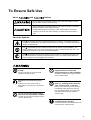
To Ensure Safe Use
About
and
Notices
Used for instructions intended to alert the user to the risk of death or severe
injury should the unit be used improperly.
Used for instructions intended to alert the user to the risk of injury or material
damage should the unit be used improperly.
* Material damage refers to damage or other adverse effects caused with
respect to the home and all its furnishings, as well to domestic animals or
pets.
About the Symbols
The
symbol alerts the user to important instructions or warnings. The specific meaning of
the symbol is determined by the design contained within the triangle. The symbol at left means
"danger of electrocution."
The
symbol alerts the user to items that must never be carried out (are forbidden). The
specific thing that must not be done is indicated by the design contained within the circle. The
symbol at left means the unit must never be disassembled.
The
symbol alerts the user to things that must be carried out. The specific thing that must
be done is indicated by the design contained within the circle. The symbol at left means the
power-cord plug must be unplugged from the outlet.
Do not disassemble, repair, or
modify.
Doing so may lead to fire or abnormal
operation resulting in injury.
Ground the unit with the ground
wire.
Failure to do so may result in risk of
electrocution in the event of a mechanical
problem.
Do not use with any power supply
other than the dedicated AC adapter.
Do not use with any electrical power
supply that does not meet the
ratings displayed on the AC adapter.
Use with any other power supply may lead
to fire or electrocution.
Do not use while in an abnormal
state (i.e., emitting smoke, burning
odor, unusual noise, or the like).
Doing so may result in fire or electrocution.
Immediately unplug the power-cord plug
from the electrical outlet, and contact your
authorized Roland DG Corp. dealer or
service center.
Use with any other power supply may lead
to fire or electrocution.
Use only with the power cord
included with this product.
Use with other than the included power cord
may lead to fire or electrocution.
3
Do not use with a damaged AC
adapter, power cord, or power-cord
plug, or with a loose electrical outlet.
Doing so may lead
to fire, electrical
shock, or
electrocution.
Do not damage or modify the
electrical power cord, subject it to
excessive bending, twisting, pulling,
binding, or pinching, or place any
object or weight on it.
Doing so may
damage the
electrical power
cord, leading to
fire, electrical
shock, or
electrocution.
When not in use for several hours,
unplug the power-cord plug from the
electrical outlet.
Failure to do so may
result in danger of
electrical shock,
electrocution, or fire
due to deterioration of
electrical insulation.
When unplugging the electrical
power cord from the power outlet,
grasp the plug, not the cord.
Unplugging by
pulling the cord
may damage it,
leading to fire,
electrical shock,
or electrocution.
4
Do not attempt to unplug the powercord plug with wet hands.
Doing so may
result in electrical
shock or
electrocution.
Do not allow liquids, metal objects
or flammables inside the machine.
Such materials
can cause fire.
Install on a stable surface.
Failure to do so
may result in the
unit tipping over,
leading to injury.
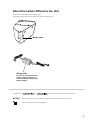
About the Labels Affixed to the Unit
These labels are affixed to the body of this product.
The following figure describes the location and content of these messages.
Model name
Rating label
Do not use with any electrical
power supply that does not
meet the ratings displayed on
the AC adapter.
In addition to the
NOTICE
and
symbols, the symbols shown below are also used.
: Indicates information to prevent machine breakdown or malfunction and ensure correct use.
: Indicates a handy tip or advice regarding use.
5
1 What to Do Before Marking
What's Metaza?
This machine is a metal printer.
It can mark photographs, drawings, text, and the like on the surfaces of flat metal and plastic. For more information about materials that
can be marked, see "2-1 Getting Ready to Perform Marking."
How the Machine Works
This machine uses a diamond tipped stylus to mark the surface of metal or plastic, creating intricate depressions.
The size of the depressions is varied by controlling the marking force, making it possible to express light and dark areas of the image.
This is exactly analogous to the way a monochrome printer expresses light and dark area by varying the size and arrangement of dots.
Printer
METAZA
If the marking force is not varied according to the hardness of the metal, different marking results will be obtained for the same image.
However, there is no need to make troublesome settings.
Just use the included Windows driver and choose the composition of the material you want to mark.
Choosing the composition automatically selects the suitable marking force for the material.
Even when the composition is the same, strength may vary if the casting method or post-machining method is changed. In such cases,
make fine adjustments in the marking force. (You can save the adjustment results in a file.)
6
1 What to Do Before Marking
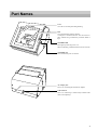
Part Names
Cover
Close the cover when performing marking.
Base
You can detach this from the machine.
A workpiece is loaded on the base. You can secure it in
place without using commercially available adhesive
tape.
STANDBY LED
This lights up when the power is on.
When it is flashing, it indicates that an error has occurred.
[STANDBY] key
This switches the power on and off.
AC adapter jack
This is for connecting the included AC adapter.
USB connector
This is for connecting a commercially available USB
cable (sold separately).
7
1 What to Do Before Marking
1
What to Do Before Marking
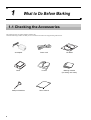
1-1 Checking the Accessories
The following items are packed together with the unit.
Check the following to make sure that you received all the items that were shipped along with the unit.
8
AC adapter
Power cord
CD-ROM
Base
Leveler
Marking material
(for testing use: brass)
Phillips screwdriver
User's manual
1 What to Do Before Marking
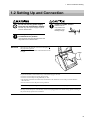
1-2 Setting Up and Connection
Do not use with any power supply
other than the dedicated AC adapter.
Use with any other power supply may lead
to fire or electrocution.
Install on a stable surface.
Failure to do so
may result in the
unit tipping over,
leading to injury.
Use only with the power cord
included with this product.
Use with other than the included power cord
may lead to fire or electrocution.
NOTICE
When moving the machine, as shown in the figure, do
not grasp the top portion.
Grip the bottom of the machine with both hands on the
left right.
To prevent accidents, do not install in any of the following types of areas.
• Avoid use in areas subject to strong electric noise.
• Avoid use in areas subject to high humidity or dust.
• This machine generates heat when used, and should not be installed in an area with poor heat radiation
characteristics.
• Do not install in an area subject to strong vibration.
Use within a temperature range of 10 to 30°C (50 to 86°F) and within a humidity range of 35 to 80%.
Securely connect the power cord that they will not be unplugged and cause failure during operation. Doing so
may lead to faulty operation or breakdown.
9
1 What to Do Before Marking
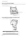
Remove the Protective Media
The protective media shown below is attached to this machine when it is shipped from the factory. When you have finished installing the
machine, remove the protective media.
Remove the packing material and screw.
Packing material
Use the Phillips screwdriver to
remove the screw.
Connecting the AC Adapter and Power Cord
Connect in the order of the numbers shown in the figure.
1
2
3
NOTICE
Do not connect the USB cable yet.
You connect the USB cable when you install and set up the software.
☞ See "1-3 Installing and Setting Up to the Software."
10
1 What to Do Before Marking
1-3 Installing and Setting Up to the Software
System Requirements
System Requirements for Installing the Software
Operating system
Computer
Computer running Windows (Pentium processor or better recommended)
Drive
CD-ROM drive
Monitor
Windows-compatible monitor capable of displaying 256 colors or more
Memory (RAM)
Free hard-disk space
required for installation
Interface
Windows 98/Me/2000/XP
64 MB or more recommended
5 MB
USB port
System Requirements for USB Connection
Making a USB connection with Windows requires use of a computer that meets all of the following system requirements. Please note that other configurations cannot be supported.
Operating system Windows 98/Me/2000/XP (Windows 95 and Windows NT4.0 are not supported.)
Computer
1) Computers preinstalled with Windows 98/Me/2000/XP at the time of purchase
(This includes such computers later upgraded to Windows Me/2000/XP.)
2) Computers on which USB operation is assured by the manufacturer of computers
• The ability to make a USB connection depends on the specifications of the computer. To determine whether the
computer you're using is capable of correct USB operation, check with the manufacturer of the computer.
• Use a shielded USB cable having a length of 3 meters or less. Do not use a USB hub or the like.
11
1 What to Do Before Marking
Installing Dr.METAZA2
Dr.METAZA2 is a program for using the machine to mark images on the surface of materials.
The steps for installing Dr.METAZA2 following installing the driver is shown below.
12
1
Switch on the computer and start Windows.
If you are installing under Windows XP/2000, log on an
account with "Administrators" rights.
For more information about account, refer to the documentation for Windows.
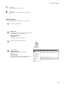
2
Place the included CD-ROM in the CD-ROM drive.
The Setup menu appears automatically.
3
Click [Dr.METAZA2 Install].
The Setup program starts.
4
Follow the messages to carry out setup and finish setting
up the program.
1 What to Do Before Marking
Installing the Driver
A driver must be installed in order to operate the machine.
Follow the steps below to install.
Windows XP
NOTICE
Keep the machine and the computer unconnected until you carry out this installation operation. Failure
to follow the correct procedure may make installation impossible.
☞ See "Installing the Driver"
"What to Do If Installation Is Impossible."
1
Before you start installation and setup, make sure the USB
cable is not connected.
2
Appear the setup menu of the CD-ROM.
3
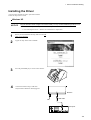
Press the [STANDBY] key to switch on the machine.
4
Connect the machine using a USB cable.
The [Found New Hardware Wizard] appears.
Machine
USB cable
Computer
13
1 What to Do Before Marking
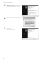
5
Choose [Install the software automatically (Recommended)], then click [Next].
Installation of the USB driver starts automatically.
14
6
When the screen appears, click [Continue Anyway].
7
Click [Finish].
This completes the installation.
1 What to Do Before Marking
Windows 98/Me/2000
NOTICE
Keep the machine and the computer unconnected until you carry out this installation operation. Failure
to follow the correct procedure may make installation impossible.
☞ See "Installing the Driver"
"What to Do If Installation Is Impossible."
1
Before you start installation and setup, make sure the USB
cable is not connected.
2
Appear the setup menu of the CD-ROM.
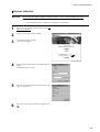
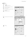
3
Click [METAZA Driver Install].
The next screen appears.
4
Select [Install]. From [Port] box, select [USB], then click
[Start].
Installation of the driver starts.
5
When all installation finishes, the screen shown at right
appears. Click [Close].
6
When the setup menu for installation reappears, click
.
15
1 What to Do Before Marking
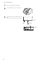
7
Remove the CD-ROM from the CD-ROM drive.
8
Press the [STANDBY] key to switch on the machine.
9
Connect the machine to your computer using a USB
cable.
The driver is automatically registered in your computer.
Machine
USB cable
Computer
16
1 What to Do Before Marking
What to Do If Installation Is Impossible
If installation quits partway through, or if the wizard does not appear when you make the connection with a USB cable, take action as
follows.
Windows XP/2000
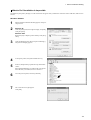
1
If the [Found New Hardware Wizard] appears, click [Finish] to close it.
2
Windows XP
Click the [Start] menu, then right-click [My Computer].
Click [Properties].
Windows 2000
Right-click [My Computer] on the desktop. Click [Properties].
3
Click the [Hardware] tab, then click [Device Manager].
The [Device Manager] appears.
4
At the [View] menu, click [Show hidden devices].
5
In the list, find [Printers] or [Other device], then doubleclick it.
When [Roland MPX-60] or [Unknown device] appears
below the item you selected, click it to choose it.
6
Go to the [Action] menu, and click [Uninstall].
7
The screen shown at right appears.
Click [OK].
17
1 What to Do Before Marking
8
9
Close the [Device Manager] and click [OK].
10
Uninstalling the driver.
Follow the procedure in the next section "Uninstalling
the Driver", step 3 and after to uninstall the driver.
11
Follow the procedure in "Installing the Driver" to redo
installation from the beginning.
Unplug the USB cable from your computer.
Windows 98/Me
18
1
Unplug the USB cables from your computer.
2
Appear the setup menu of the CD-ROM.
3
Uninstalling the driver.
Follow the procedure in the next section "Uninstalling
the Driver", step 3 and after to uninstall the driver.
4
Follow the procedure in "Installing the Driver" to redo
installation from the beginning.
1 What to Do Before Marking
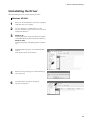
Uninstalling the Driver
When uninstalling the driver, perform following operation.
Windows XP/2000
1
Before you start uninstallation of the driver, unplug the
USB cables from your computer.
2
Log on to Windows as “Administrators” account.
For more information about account, refer to the documentation for Windows.
3
Windows XP
From the [Start] menu, click [Control Panel]. Click [Printers and Other Hardware], then click [Printers and Faxes].
Windows 2000
From the [Start] menu, click [Setting]. Then Click [Printers].
4
If [Roland MPX-60] appears, click the [Roland MPX60] icon.
From the [File] menu, choose [Delete].
5
When the screen prompting you to confirm deleting appears, click [Yes].
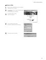
6
From [File] menu, click [Server Properties].
The next screen appears.
19
1 What to Do Before Marking
20
7
Click the [Drivers] tab.
If [Roland MPX-60] appears, choose [Roland MPX-60]
from the list, then click [Remove].
8
When the screen prompting you to confirm deleting appears, click [Yes].
9
Insert the Roland Software Package CD-ROM into the
CD-ROM drive.
The setup menu appears automatically.
10
Click [METAZA Driver Install].
The next screen appears.
11
Select [Uninstall], then click [Start].
12
Click [Yes] to restart the computer.
When driver is deleted, the next screen appears.
1 What to Do Before Marking
Windows 98/Me
1
Before you start uninstallation of the driver, unplug the
USB cables from your computer.
2
Insert the Roland Software Package CD-ROM into the
CD-ROM drive.
The setup menu appears automatically.
3
Click [METAZA Driver Install].
The next screen appears.
4
Select [Uninstall], then click [Start].
5
Click [Yes] to restart the computer.
When driver is deleted, the next screen appears.
21
2 Performing Marking
2
Performing Marking
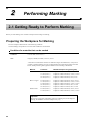
2-1 Getting Ready to Perform Marking
Before you start marking, have on hand a workpiece and an image for marking.
Preparing the Workpiece for Marking
Provide a workpiece that meets all of the following conditions.
Correct marking is not possible if even one of the conditions is not satisfied.
Conditions for materials that can be marked
Thickness
0.3 to 20 mm (0.01 to 0.8 in.)
Size
Length (or width) of 90 mm (3-9/16 in.) or less
* Note that even if thickness and size are within the range as described above, it may not be
possible to perform marking correctly on materials that warp when struck. Refer to the table
below, which provides a general guide to markable sizes according to thicknesses.
Material
Thickness
Markable workpiece size (general guide)
Aluminium
2.0 mm (0.08 in.)
1.5 mm (0.06 in.)
1.0 mm (0.04 in.)
0.5 mm (0.02 in.)
0.3 mm (0.01 in.)
Length (or width) of 60 mm (2-3/8 in.) or less
Length (or width) of 40 mm (1-9/16 in.) or less
Length (or width) of 30 mm (1-3/16 in.) or less
Length (or width) of 20 mm (3/4 in.) or less
Length (or width) of 20 mm (3/4 in.) or less
Brass or copper
2.0 mm (0.08 in.)
1.5 mm (0.06 in.)
1.0 mm (0.04 in.)
0.5 mm (0.02 in.)
0.3 mm (0.01 in.)
Length (or width) of 60 mm (2-3/8 in.) or less
Length (or width) of 40 mm (1-9/16 in.) or less
Length (or width) of 30 mm (1-3/16 in.) or less
Length (or width) of 15 mm (9/16 in.) or less
Length (or width) of 15 mm (9/16 in.) or less
Stainless steel
2.0 mm (0.08 in.)
1.0 mm (0.04 in.)
Length (or width) of 60 mm (2-3/8 in.) or less
Length (or width) of 40 mm (1-9/16 in.) or less
Important!
The sizes are suggestions. Depending on the size (marking area) of the image for
marking, the markable size of the workpiece may vary.
22
2 Performing Marking
Hardness of surface
to mark
Vickers hardness (HV) of 200 or less
Shape of surface to
mark
Flat, with no difference in level
* Note that materials which may crack or split by marking (such as glass, stone, precious
stones, china, and porcelain) cannot be marked even if hardness is within the preceding range.
Attempting to mark such materials may damage the machine.
- Examples of material that cannot be marked
Edge of the
material is too high.
Shape of the back of
the surface to mark
Surface to mark
is not straight.
When placed on the base, the surface to mark must be flat and level.
- Examples of material that cannot be marked
Back surface is
uneven.
Back surface is
not straight.
Back surface is
curved.
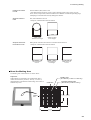
About the Marking Area
The marking area of this machine is as shown below.
Important!
When marking is performed in an expanded area (that is,
outside an area of 50 by 50 mm (1-15/16 by 1-15/16 in.)),
then depending on the material and the image, unevenness in
darkness may occur.
Marking area
(50 x 50 mm (1-15/16 x 1-15/16 in.))
Center line
Center
line
Expanded marking area
(80 x 80 mm (3-1/8 x 3-1/8 in.))
50 mm
80 mm
(1-15/16 in.) (3-1/8 in.)
50 mm
(1-15/16 in.)
80 mm
(3-1/8 in.)
23
2 Performing Marking
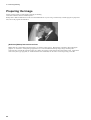
Preparing the Image
Prepare an image (such as a photograph or drawing) for marking.
Vector data cannot be used. Provide bitmap data.
Bitmap data in JPEG or BMP format can be used with Dr.METAZA2. If you're using a commercially available program to prepare the
data, refer to the program documentation.
[Definition] Bitmap Data and Vector Data
Bitmap data uses a format that represents images as a collection of dots (points). Bitmap data is sometimes called "bitmapped
graphics" or "raster data." Most paint-type applications (ex. Paint and Adobe Photoshop) display images as bitmap data.
Vector data uses a format that represents images as a number of reference points and lines that connect these points. Applications
such as many draw-type programs (ex. Adobe Illustrator and CorelDRAW) can be used to create images using vector data.
24
2 Performing Marking
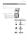
2-2 Loading the Workpiece
1
Open the cover.
2
Grasp the base on both sides and pull back toward you
to remove.
3
Place the workpiece so that the center of the place to
mark is aligned with the center of the scale.
Important!
Powder or dust on the adhesive sheet can reduce the
sheet's adhesive force, making it impossible to secure
material in place.
If the adhesive force has been reduced, then wash the
adhesive sheet. Washing the sheet revitalizes its adhesive force. For information on how to clean the adhesive
sheet, take a look at "4 Maintenance", "Cleaning the Adhesive Sheet."
Marking location
on the image
Location where the workpiece
is placed on the base
Center line
Center
line
25
2 Performing Marking
26
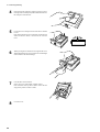
4
Press down on the workpiece gently to secure it in place.
Pressing down forcefully may make it difficult to remove
the workpiece from the base.
5
Loosen the screw and press down from above with the
leveler.
Press down until the leveler completely touches the top
surface of the base. There is no need to use excessive
force.
6
While pressing down with the leveler, tighten the screw.
When tightening the screw, be careful not to let the height
of the surface to be marked change.
7
Load the base on the machine.
Slowly press it in inward until it makes contact.
Press it inward securely until it makes contact. Do not
stop partway, before contact is made.
8
Close the cover.
2 Performing Marking
2-3 Performing Marking
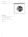
This section explains the steps of actual marking, using the brass medallion shown below as an example.
30 mm
(1-1/8 in.)
Congratulation
Creating Marking Data
Create the data for marking the workpiece.
Import the photograph (or drawing) you prepared in "2-1 Getting Ready to Perform Marking," and design the data import mark.
In this example, we'll use Dr.METAZA2 as the design tool for the marking data. If you're using a commercially available program to
prepare the data, refer to the user's documentation for the program.
NOTICE
Leave a margin of 1 mm (1/16 in.) or more from the edges of the workpiece.
Performing marking right up to the full dimensions of the workpiece may shorten the service life of the head.
Starting Dr.METAZA2
1
Windows XP
Click [Start] and point to point to [All Programs].
Point to [Roland Dr.METAZA2] and click
[Dr.METAZA2].
Windows 98/Me/2000
Click [Start] and point to [Programs].
Point to [Roland Dr.METAZA2] and click
[Dr.METAZA2].
After the opening screen, the screen for Dr.METAZA2 appears.
27
2 Performing Marking
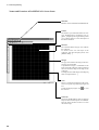
Names and Functions of Dr.METAZA2's Screen Items
Menu Bar
Runs the various commands for Dr.METAZA2.
Toolbar
The toolbar is provided with buttons for running Dr.METAZA2 commands such as
[Open...] and [Save]. Moving the mouse pointer
over a button displays a brief description of
the button's function.
Material
The combined black and gray areas indicate
the workpiece.
To decide on the size and shape of the
workpiece, then from the [File] menu, click
[Material Setup...].
Margin
The gray area indicates the margin. The margin areas are not marked.
A quadrilateral margin is established on the
inner side of the workpiece. Please note that it
does not follow the shape of the edges of the
workpiece.
To change the size of the margin, from the [File]
menu, click [Preferences...].
Grid
This is a grid of lines displayed on the screen.
It serves as a guide for positioning images and
text.
To hide the displayed grid, click
the selection.
to clear
Status Bar
This shows Dr.METAZA2's state of operation
and provides brief descriptions of commands.
This also shows amount of zoom in or zoom
out for the image.
28
2 Performing Marking
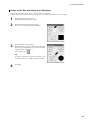
Decide on the Size and Shape of the Workpiece
Enter the size (outer dimensions) of the workpiece, and choose the shape.
In this example, enter a size of 30 mm by 30 (1-1/8 in. by 1-1/8) shape, and choose a circle as the shape.
1
From the [File] menu, click [New...].
The [Material Setup] dialog box appears.
2
Enter the outer dimensions of the workpiece.
Here, enter "30" for both [Height] and [Width].
3
Choose the shape of the workpiece.
If the shape is a circle (ellipse), quadrilateral or diamond,
click the corresponding shape icon. To choose another
registered shape, click [Other...].
In this example, click
.
Tip
To register a shape that is not listed, click [Add...]. For
more information, see "3-1 Adding a Workpiece Shape."
4
Click [OK].
29
2 Performing Marking
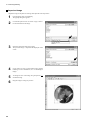
Import an Image
Import the image of the photo or drawing, then adjust the size and position.
30
1
From the [File] menu, click [Import].
The [Open] dialog box appears.
2
Click the drop-down arrow for "Files of type," then select the file format of the image.
3
Select the desired file, then click [Open].
The specified image is imported and displayed on the
screen.
4
If you want to use only a portion of the image, perform
trimming. For more information, see "3-2 Trimming an
Image."
5
To change the size of the image, drag the pointers ( )
around the image.
6
Drag the image to change its position.
2 Performing Marking
Add Text
Add text to the image.
1
Click
2
Click the location where you want to insert text.
The [Text] dialog box appears.
3
Enter the text in [Text].
In this example, enter "Congratulations" as the text.
4
Click [Change...].
The [Font] dialog box appears.
5
Choose the font, style, and size, then click [OK].
6
Click [OK].
, select [Horizontal Text].
31
2 Performing Marking
7
Drag the center of the text to position it at the desired
location.
Save the File
When you're finished creating the marking data, save it in a file.
32
1
From the [File] menu, click [Save].
The [Save As] dialog box appears.
2
Choose where to save the file, then type a filename.
3
Click [Save].
2 Performing Marking
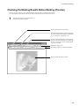
Checking the Marking Results Before Marking (Preview)
You can see an on-screen preview of the image after marking before you actually start marking.
You can brightness and contrast of the image while viewing the expected results on the screen.
1
From the [File] menu, click [Print Preview...].
The [Preview] window appears.
Click to close the [Preview] window.
This returns the brightness, contrast, and gamma
correction settings to their default values (brightness: 0, contrast: 0, and gamma: 0.5).
Click to send the marking data to the machine.
For more information about how to send marking data, see the next section "Starting Marking," step 3 and after.
Change the display scale.
Change the brightness, contrast and gamma.
Drag to change the display position.
33
2 Performing Marking
Starting Marking
NOTICE
After you switch on the machine, initialization is performed. Do not attempt to open the cover or move the base
until initialization ends. Wait until initialization finishes before attempting to mount the base.
Operate Dr.METAZA2 to send marking data to the machine.
* When changing the settings for the various items under Windows XP/2000, log on an account with "Administrators" right.
1
If the power to the machine is off, press the [STANDBY]
key to switch it on.
Power-on initialization is performed, then operation
stops.
The power-on initialization performs origin detection, and so a noise may be heard.
34
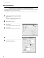
2
From the [File] menu, click [Print].
The [Print] dialog box appears.
3
Click the drop-down arrow for "Name," then click
[Roland MPX-60].
If this is already selected, then go on to the next step.
4
Click [Properties].
The [Roland MPX-60 Properties] dialog box appears.
5
Click [Image Correction] tab.
6
Click the drop-down arrow in the figure, then click the
composition of the workpiece.
In this example, choose [Brass].
2 Performing Marking
7
Click [OK].
The [Print] dialog box appears again.
8
Click [OK].
The marking data is sent to the machine, and marking
starts.
Stop Marking
To stop marking partway through, carry out the steps below.
1
2
Press the [STANDBY] key.
Windows XP
Click [Start]-[Control Panel] and then click [Printers and
Other Hardwares]- [Printers and Faxes].
Windows 98/Me/2000
Click [Start].
Point to [Settings] and click [Printers].
3
Double-click the [Roland MPX-60] icon.
4
Stop sending data.
Windows XP/2000
From the [Printer] menu, click [Cancel All
Documents].
Windows 98/Me
From the [Printer] menu, click [Purge Print Jobs] or
[Purge Print Documents] to stop sending data.
35
2 Performing Marking
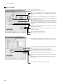
Driver Settings
Refer to this description for making settings for items other than the ones described earlier.
Enter the size of the marking area.
This corrects misalignment of the center point. For more information, see "5 Troubleshooting", "The marked location isn't where
desired."
This chooses the units of measurement for the width and length.
This expands the marking area (this can be set up to a maximum of
80 x 80 mm (3-1/8 x 3-1/8 in.).
However, note that when marking is performed in an expanded area
(that is, outside an area of 50 x 50 mm (1-15/16 x 1-15/16 in. )), then
depending on the material and the image, unevenness in darkness
may occur.
To view the image during marking while marking is in progress,
make sure this is selected.
If quality is a priority, switch this off. Note that the time required for
marking is increased.
This saves the driver settings in a file.
This loads driver settings saved in a file.
This performs adjustment when the marking results are not what
you intended. See "5 Troubleshooting", "Images are unattractive."
This returns the corrected image values to the initial values before
correction (brightness = 0, contrast = 0, and gamma = 0.5).
This chooses the composition of the material to mark.
The optimal marking force for the material to mark is set. To make
fine adjustments in the marking force, click [Details...].
Choose Text when printing text or images with clearly defined outlines.
Choose Photo when printing photographs or other images that contain gradations.
This marks a mirror image of the marking image.
36
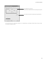
2 Performing Marking
This adjusts the tilt of the base.
Enter the values taken from the results of marking the test pattern.
This marks the test pattern for adjusting tilt using the machine.
For information about how to adjust the tilt of the base, see "5 Troubleshooting", "The image at the same location is always too light
(or too dark), or the image is uneven."
37
2 Performing Marking
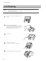
2-4 Finishing
NOTICE
Do not attempt to open the cover or move the base until marking has ended completely and the base has
returned to its original location.
Doing so may lead to faulty operation or breakdown.
When marking ends, remove the workpiece and switch off the power.
38
1
Grasp the base on both sides and pull back toward you
to remove.
2
Remove the workpiece from the base.
If the workpiece is difficult to detach, inserting a thin,
flat object (such as a piece of sheet metal or a piece of
stiff paper) between the adhesive sheet and the material
may make the workpiece easier to remove.
3
Loosen the screw.
4
Load the base on the machine.
Slowly press it in inward until it makes contact.
5
Press the [STANDBY] key to switch off the power.
3 Dr.METAZA2 Guide
3
Dr.METAZA2 Guide
3-1 Adding a Workpiece Shape
If you want to use a workpiece having a shape other than a circle (ellipse), quadrilateral, or diamond, you need to add the shape.
You can use either of two methods to register a shape with Dr.METAZA2.
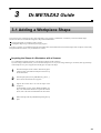
Acquiring the shape of a workpiece with a scanner
Creating the shape using a commercial paint-type program
If you have a scanner, we recommend using the first method. The second method can be used if the shape of the workpiece cannot easily
be acquired with the scanner, or if you don't have a scanner.
Acquiring the Shape of a Workpiece with a Scanner
Use a TWAIN32-compliant scanner to scan the shape (outline) of the workpiece.
If you are using a flat-bed scanner, you can scan the workpiece as it is. If you are using another type of scanner, then copy the shape
of the workpiece to a piece of paper and scan the paper to acquire the shape.
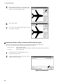
1
Place the workpiece on the scanner. Alternatively, place
a sheet of paper onto which the workpiece has been copied on the scanner.
2
From the [File] menu, click [Add Material] - [Scan...].
The screen for the scanner driver appears.
3
Operate the scanner driver to scan the shape of the
workpiece.
For the number of colors, select "Black and White" (binary). For information about how to operate the scanner
driver, refer to the user's documentation for the scanner.
4
When scanning ends, the [Add Material] dialog box appears.
39
3 Dr.METAZA2 Guide
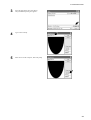
5
In the [Add Material] dialog box, for [Resolution], enter
the same value as the resolution you specified with the
scanner driver when performing scanning.
6
Type a name of shape.
7
Use preview to check the shape of the workpiece, and if
it's acceptable, click [Add].
Creating the Shape Using a Commercial Paint-type Program
You can use a commercial paint-type program to create a shape, then register it with Dr.METAZA2.
Vector data cannot be used. Prepare bitmap data that meets the offer conditions.
1
2
40
Number of colors:
Binary (black and white)
(Fill the interior of the shape with black, and make other portions white or uncolored.)
File format:
BMP or JPEG format
From the [File] menu, click [Add Material] - [File...].
The [Open] dialog box appears.
Click the drop-down arrow for "Files of type," then select the file format of the image.
3 Dr.METAZA2 Guide
3
Select the desired file, then click [Open].
The [Add Material] dialog box appears.
4
Type a name of shape.
5
Enter the size of the workpiece, then click [Add].
41
3 Dr.METAZA2 Guide
3-2 Trimming an Image
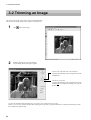
This specifies the range of the image to import into Dr.METAZA2.
You can trim an original image to leave just the required portion.
1
Click
2
From the [Object] menu, click [Trimming].
The [Trimming Picture] dialog box appears.
and click the image.
Trim an area of the same size as the workpiece.
To change the trimming location, drag the inside of the
shaded frame.
Trim the area you want.
To change the trimming location, drag the inside of the
shaded frame. To change the trimming size, drag the
pointers ( ).
If you're not satisfied with the trimming area, you can do it over as many times as you like.
However, you can only redo the operation after importing the image until you quit Dr.METAZA2. To change the trimming area after
that, reimport the original image.
42
3 Dr.METAZA2 Guide
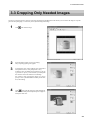
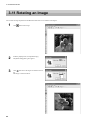
3-3 Cropping Only Needed Images
You can crop just the necessary portion of an image imported into Dr.METAZA2. This means you can extract the image of a specific
person from a photograph, or conversely extract just the background image.
1
Click
2
From the [Object] menu, click [Crop Image].
The [Crop Image] dialog box appears.
3
To change the color used to indicate areas specified as
transparent locations, click [Transparent Color].
To make it easier to identify the cropped area, it may be
a good idea to specify a color that lets you distinguish
the contours of the area from their surroundings.
For example, when cropping the image of a person,
specify a color system that differs from the person's hair,
skin, and clothing.
4
and click the image.
Click
, then click the location to make transparent.
This fills the clicked pixel and adjacent pixels of approximately the same color.
43
3 Dr.METAZA2 Guide
5
If the area filled is too extensive or insufficient, you
can redo the operation.
Click
, change the value for [Approximate Color
a second time.
for Fill], then click
To enlarge the area filled, make the value larger. To
reduce the area, make the value smaller.
Specify the approximate transparent location by
repeating this process of clicking as you vary the fill
area.
6
After you have specified the approximate transparent
area, finish using the pen tool.
Click
parent.
7
, then click the area you want to make trans-
To change the width of the pen, change the value for
[Pen Diameter].
Tip
Another method is to use the pen tool to trace the outline
of the image you want to crop, then use the fill tool to
perform finishing in a single step.
When the outline is composed of straight lines, this
method may enable you to accomplish the task more
easily.
When you know ahead of time that cropping will be performed, using colors of the same type for the background
enables you to perform cropping quickly and easily.
One example of this would be taking a photo of a person
with a single-color wall as the background.
44
3 Dr.METAZA2 Guide
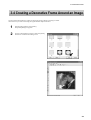
3-4 Creating a Decorative Frame Around an Image
You can use the Frame feature to achieve an effect like placing a photo or painting in a frame.
Choose the one you want from among the registered frame shapes and colors.
1
From the [Object] menu, click [Frame].
The [Frame] dialog box appears.
2
Click on a frame pattern to choose it, then click [Insert].
The frame is inserted in the editing screen.
45
3 Dr.METAZA2 Guide
46
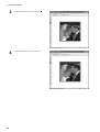
3
To change the frame size, drag the pointers ( ).
4
To change the frame location, drag the frame.
3 Dr.METAZA2 Guide
3-5 Registering a Frequently Used Image (Symbol)
You can register often-used images, such as company or organization logos, as symbols.
Registering a image that allows wide use can reduce image-importing operations, boosting task efficiency.
1
From the [Object] menu, click [Add Parts] - [Symbol].
The [Open] dialog box appears.
2
Select the desired file, then click [Open].
The [Add Symbol] dialog box appears.
3
To show the image underneath when a symbol is inserted,
specify a transparent color.
Click [Transparent].
The [Crop Image] dialog box appears.
Tip
To make a portion of an image transparent, refer to "3-3
Cropping Only needed Images."
4
Type a symbol name, then click [Add].
47
3 Dr.METAZA2 Guide
3-6 Importing an Image from a Scanner
If you have a TWAIN32-compliant scanner, you can call up the scanner driver from Dr.METAZA2.
For information on connecting a scanner and installing the scanner driver, refer to the user's documentation for the scanner.
48
1
From the [File] menu, click [Acquire...].
The screen for the scanner driver appears.
2
Operate the scanner driver to scan the image.
For information about how to operate the scanner driver,
refer to the user's documentation for the scanner.
3
When scanning ends, the scanned image appears on the
Dr.METAZA2 screen.
3 Dr.METAZA2 Guide
3-7 Adding a Hand-drawn Image or Text
You can use the mouse to write text or draw a picture by hand and add it to the acquired image.
To acquire a picture or text drawn or written on paper, see "3-1 Adding a Workpiece Shape."
1
2
Click
.
Drag the mouse to draw the picture or write text.
3
To change the pen width or color, from the [Object] menu,
click [Pen Setup].
The [Pen Setup] dialog box appears.
4
To change the pen width, drag the [Width] slider to the
left or right.
To change the pen color, click [Pen & Paint Color].
5
To delete a picture or text made with the pen tool, rightdrag with the mouse.
49
3 Dr.METAZA2 Guide
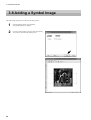
3-8 Adding a Symbol Image
This adds images registered as symbols to the editing screen.
50
1
From the [Object] menu, click [Symbol].
The [Symbol] dialog box appears.
2
Click on a symbol image to choose it, then click [Insert].
The symbol is inserted in the editing screen.
3 Dr.METAZA2 Guide
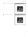
3
To change the image size, drag the pointers ( ).
4
To change the image location, drag the image.
51
3 Dr.METAZA2 Guide
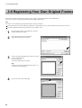
3-9 Registering Your Own Original Frames
You can use a commercial paint-type program to create a shape yourself, then register it with Dr.METAZA2.
Vector data cannot be registered. Prepare bitmap data in BMP or JPEG format.
Tip
For frames, we recommend using images that meet the following conditions.
Use images that do not contain continuous gradations or a large number of colors. (We recommend using only about 16 colors.)
Use clearly defined borders between transparent colors and other colors.
1
From the [Object] menu, click [Add Parts] - [Frame].
The [Open] dialog box appears.
2
Select the desired file, then click [Open].
The [Add Frame] dialog box appears.
3
To show the image underneath when a frame is inserted,
specify a transparent color.
Click [Transparent].
The [Crop Image] dialog box appears.
Tip
To make a portion of an image transparent, refer to "3-3
Cropping Only needed Images."
4
52
Type a frame name, then click [Add].
3 Dr.METAZA2 Guide
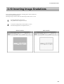
3-10 Inverting Image Gradations
This inverts the gradations of all images, including photos, frames, and the like.
You cannot invert individual objects.
Selecting [Invert] inverts the white areas of the image to black, and vice versa.
1
From the [Edit] menu, click [Invert].
The gradations of all images are inverted.
2
To check the cutting results of the machine on screen,
then from the [File] menu, click [Print Preview...].
Before inversion
After inversion
53
3 Dr.METAZA2 Guide
3-11 Rotating an Image
You can take an image imported into Dr.METAZA2 and rotate it in increments of 90 degrees.
54
1
Click
2
From the [Object] menu, click [Rotate Image].
The [Rotate Image] dialog box appears.
3
Click
, then choose the angle of rotation for the image.
The image is rotated clockwise.
and click the image.
3 Dr.METAZA2 Guide
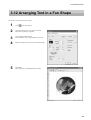
3-12 Arranging Text in a Fan Shape
You can lay out entered text in a fan shape.
1
Click
2
Click the location where you want to insert text.
The [Fan Text] dialog box appears.
3
Go to [Text] and enter the text.
In this example, enter "Congratulations" as the text.
4
Make the settings for the font, size, and rotation angle.
5
Click [OK].
The text appears in the Dr.METAZA2 window.
, then choose [Fan].
55
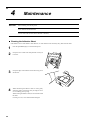
4 Maintenance
4
NOTICE
Maintenance
When cleaning, turn off the power.
Never lubricate the mechanisms.
Do not clean with solvents (such as benzine or thinners).
Cleaning the Adhesive Sheet
If the adhesive force of the adhesive sheet declines, or if the sheet becomes extremely dirty, then wash the sheet.
1
Press the [STANDBY] key to switch off the power.
2
Grasp the base on both sides and pull back toward you
to remove.
3
Grasp the edges of the adhesive sheet and slowly peel it
off the base.
4
While submersing the adhesive sheet in water, gently
stroke the surface of the sheet with your fingers. Never
use a scrubbing pad or sponge.
When washing the adhesive sheet, do not stretch or bend
the sheet.
If soiling is severe, use a diluted neutral detergent.
56
4 Maintenance
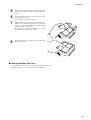
5
When you use a neutral detergent, rinse thoroughly with
water so that no detergent remains on the surface of the
sheet.
6
Allow the adhesive sheet to dry. Place out of direct sunlight until completely dry.
Never mount on the base while still wet.
7
With the scale facing up, align the rounded corner on the
adhesive sheet with the upper-right corner of the base
and set it in place. Place the sheet so that both rounded
corners are at the top of the base.
Be careful not to allow any air bubbles to be trapped
between the base and the adhesive sheet.
8
Press down gently on the adhesive sheet at the center
and the four corners.
Cleaning the Body and Cover
Use a cloth moistened with water then wrung well, and wipe gently to clean.
The surface of the cover is easily scratched, so use a soft cloth.
57
5 Troubleshooting
5
Troubleshooting
The machine doesn't run when marking data is sent.
What to check
Remedy
Is the power for the machine
switched on?
Press the [STANDBY] key to switch on the power.
Is the cable connected?
Check whether the USB cable is loose or detached.
If the cable is loose or detached, switch off the power and reconnect the cable.
Is the STANDBY LED flashing?
The STANDBY LED flashes when some error occurs in the machine.
Stop sending data and switch off the power to the machine. Eliminate the cause of
the error, then send the marking data again.
The Dr.METAZA2 does not function.
What to check
Does the computer provide the
correct system requirements for
Dr.METAZA2?
58
Remedy
Use a computer that matches the system requirements for Dr.METAZA2. For more
information about the system requirements for Dr.METAZA2, see "1-3 Installing
and Setting Up to the Software."
5 Troubleshooting
Machining is performed, but marking is not possible.
What to check
Remedy
Is the workpiece loaded at the
correct location?
If empty marking is being performed at a location other than where the workpiece is
loaded, reload the workpiece.
Does the workpiece to mark meet
the "Conditions for materials that
can be marked"?
See "2-1 Getting Ready to Perform Marking" and prepare a workpiece that can be
marked.
Images are unattractive -- faint (images are dim).
What to check
Remedy
Are the workpiece settings for the
Metaza driver correct?
Choose the composition of the loaded workpiece.
Even if the material is the same, the hardness of the marking surface may vary
greatly depending on the casting method, the composition of impurities, the presence of plating, and so on. In such cases, perform fine adjustment of the marking
force.
The image is uniformly dim.
Perform marking while increasing the brightness of [Gamma] or [Brightness] for
the machine driver a little at a time.
At this time, leave the workpiece loaded and perform overstriking at the same location. Change the driver settings and continue marking until you obtain the darkness
you want.
White is reproduced, but grayscale
tones are faint.
Choose a custom workpiece (settings A through E), and adjust the marking force.
Perform marking while leaving the value for [Impact--MAX] unchanged and increasing the value for [Impact--MIN] a little at a time.
At this time, leave the workpiece loaded and perform overstriking at the same location. Change the driver settings and continue marking until you obtain the darkness
you want.
Important!
The various setting values determined with overstriking are effective only when
performing overstriking. The same results are not necessarily obtained when marking is performed with a new workpiece under identical conditions.
Images are unattractive -- dark (all images are whitish).
What to check
Are the workpiece settings for the
Metaza driver correct?
Remedy
Choose the composition of the loaded workpiece.
Even if the material is the same, the hardness of the marking surface may vary
greatly depending on the casting method, the composition of impurities, the presence of plating, and so on. In such cases, perform fine adjustment of the marking
force.
59
5 Troubleshooting
Images are unattractive -- uneven.
What to check
Remedy
Is the marking surface slightly
uneven?
Replace with a workpiece having a level marking surface.
The marking surface is not uneven,
but image darkness is uneven.
Overstriking with a workpiece loaded at the same location may improve image quality.
Change [Gamma], [Brightness], and [Contrast], then perform overstriking with the
workpiece.
Is [Bi-Direction] selected?
Selecting [Bi-Direction] makes the time required for marking shorter but it may
cause poor image quality. In this case, change a workpiece and clear the selection
for [Bi-Direction].
Is a portion of the image missing?
The workpiece may not be loaded correctly, or there may be partial differences in
the height of the marking surface.
Load the workpiece again.
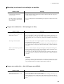
The image at the same location is always too light (or too dark), or the image is uneven.
If the image is often too light near the front-right area of the base, adjusting the tilt of the base may improve image quality. Doing this
can reduce unevenness in the image due to the marking position.
Image unevenness due to tilt is often hard to detect near the center of the base, and tends to become more conspicuous at distances
increasingly farther away from the center (especially with larger images). Adjustment for generally favorable image quality is performed
when the machine is shipped from the factory, but you should adjust the tilt to for each individual situation to achieve an optimal state.
Note that even after adjustment, image unevenness may occur that is due to factors other than tilting of the base, such as warping or
deformation of the workpiece. Also, adjustment has no effect on image unevenness that is unrelated to the marking location, such as
cases in which the location where image unevenness occurs is different with each workpiece or image.
1
Load the workpiece included with the machine at the
center of the base. If the included workpiece has been
used up, then prepare a workpiece that is larger than 60
mm and has a smoothness of 0.05 mm or less.
For information on how to load the workpiece, refer to
"2-2 Loading the Workpiece."
2
Go into the [Printers] folder. Right-click the [Roland
MPX-60] and open the setting screen for the METAZA
driver.
Windows XP/2000
Click [Printing Preferences].
Windows 98/Me
Click [Properties].
3
60
Click the [Correct Slope] tab.
5 Troubleshooting
4
Click [Test print].
The test pattern is marked on the workpiece.
5
Grasp the base on both sides and pull back toward you
to remove.
6
Use the scale to read and note down locations where the
test pattern is not continuous or not visible. Note down
the values in all four directions (front, back, left, and
right).
Back
20
15
10
5
Left
20
15
10
5
Right
5
10
15
20
5
10
15
20
Front
7
Select [Correct slope] and enter the scale values you noted
into the driver.
61
5 Troubleshooting
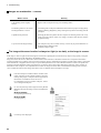
The marked location isn't where desired.
The center of the base scale may not coincide with the machine's marking origin point.
To correct displacement between the scale center and the marking origin point, follow the steps below.
1
Load an unneeded workpiece that will not be used for
marking on the base. Prepare a workpiece that is about
10 to 20 mm (1/2 to 1 in.) square.
For information on how to load the workpiece, refer to
"2-2 Loading the Workpiece."
2
Start Dr.METAZA2, and in the [Sample] folder, open
[Axis.dmz].
3
Perform marking.
4
Grasp the base on both sides and pull back toward you
to remove.
When doing this, be careful to ensure that the loaded
position of the workpiece does not change.
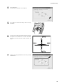
5
Measure and make a note of the displacement between
the base-scale centerlines and the crossed lines on the
workpiece.
The figure at right shows a positive displacement of 0.5
mm (0.02 in.) for [Width] and a negative displacement
of 0.5 mm (0.02 in.) for [Length].
Center line
Positive direction
for [Length]
Positive direction
for [Width]
-0.5 mm
(-0.02 in.)
0.5 mm
(0.02 in.)
6
Go into the [Printers] folder. Right-click the [Roland
MPX-60] and open the setting screen for the METAZA
driver.
Windows XP/2000
Click [Printing Preferences].
Windows 98/Me
Click [Properties].
62
Center line
Material
5 Troubleshooting
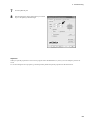
7
Click the [Material] tab.
8
Enter the dimensions of the displacement you noted in
step 5 as the [Offset] width and length.
Important!
When you open the properties for a driver from a program such as Dr.METAZA2, any values you set are temporary, and are not
saved.
To save the settings for driver properties, go into the [Printers] folder and open the properties for the desired driver.
63
Specifications
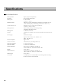
Main Unit Specifications
Printing method
Impact (single-dot configuration)
Resolution
265 dpi/212 dpi (Photo/Text)
Printing area
80 mm x 80 mm
(3-1/8 in. x 3-1/8 in.)
Printable material
Gold, silver, copper, platinum, brass, aluminium, iron, stainless steel, etc.
(Vickers hardness [HV] of the marking surface must be 200 or less.)
Loadable material size
Maximum 90 mm x 90 mm x 20 mm (thickness)
(3-1/2 in. x 3-1/2 in. x 3/4 in.)
Printing direction
Unidirectional printing or bidirectional printing
(Selectable with Windows driver)
Printing speed
15 mm/sec (9/16 in./sec)
Interface
USB interface (compliant with Universal Serial Bus Specification Revision
1.1)
Power supply
Dedicated AC adapter
Input : AC 100 to 240V ± 10% 50/60Hz 1.0A
Output : DC 19V 2.1A
64
Power consumption
Approx. 10W
Acoustic noise level
Under 70 dB (A) (According to ISO 7779)
Operation temperature
10 to 30˚C (50 to 86˚F)
Operation humidity
35 to 80% (no condensation)
External dimensions
235 mm (W) x 322 mm (D) x 215 mm (H)
(9-5/16 in. (W) x 12-11/16 in. (D) x 8-1/2 in. (H))
Weight
7.0 kg (15 lb.)
Packed dimensions
310 mm (W) x 385 mm (D) x 320 mm (H)
(12-1/4 in. (W) x 15-1/4 in. (D) x 12-3/4 in. (H))
Packed weight
9.0 kg (20 lb.)
Accessories
AC adapter, power cord, CD-ROM, leveler, marking material for testing,
phillips screwdriver and user's manual
Please read this agreement carefully before opening the sealed
package or the sealed disk package
Opening the sealed package or sealed disk package implies your acceptance of the terms and conditions of this agreement.
Roland License Agreement
Roland DG Corporation ("Roland") grants you a non-assignable and non-exclusive right to use the COMPUTER
PROGRAMS in this package ("Software") under this agreement with the following terms and conditions.
1. Coming into Force
This agreement comes into force when you purchase and open the sealed package
or sealed disk package.
The effective date of this agreement is the date when you open the sealed package
or sealed disk package.
2. Property
Copyright and property of this Software, logo, name, manual and all literature
for this Software belong to Roland and its licenser.
The followings are prohibited :
(1) Unauthorized copying the Software or any of its support file, program module
or literature.
(2) Reverse engineering, disassembling, decompiling or any other attempt to
discover the source code of the Software.
3. Bounds of License
Roland does not grant you to sub-license, rent, assign or transfer the right granted
under this agreement nor the Software itself (including the accompanying items)
to any third party.
You may not provide use of the Software through time-sharing service and/or
network system to any third party who is not individually licensed to use this
Software.
You may use the Software by one person with using a single computer in which
the Software is installed.
4. Reproduction
You may make one copy of the Software only for back-up purpose. The property
of the copied Software belongs to Roland.
You may install the Software into the hard disk of a single computer.
5. Cancellation
Roland retains the right to terminate this agreement without notice immediately
when any of followings occurs :
(1) When you violate any article of this agreement.
(2) When you make any serious breach of faith regarding this agreement.
6. Limitations on Liability
Roland may change the specifications of this Software or its material without
notice.
Roland shall not be liable for any damage that may caused by the use of the
Software or by exercise of the right licensed by this agreement.
7. Governing Law
This agreement is governed by the laws of Japan, and the parties shall submit to
the exclusive jurisdiction of the Japanese Court.
R1-040209