1
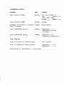
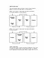
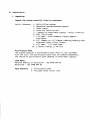
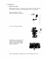
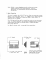
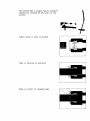
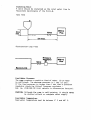
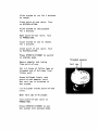
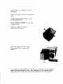
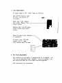
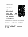
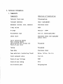
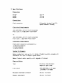
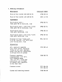
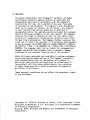
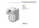
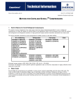
iilli-Q* Plus
Water Purification System
Installation and Operation
M1LUPORE
MILLI-Q PLUS
A. Introduction
1.
2.
3.
4.
5.
System Description
External Features
Schematic
Dimensions
Function of Components/Controls
B. Installation
1.
2.
3.
4.
5.
6.
7.
Unpacking
Battery Insertion
Water Connection
Electrical Connection
Bench/Wall Mounting
Pack Installation
Initial Startup
C. Operation
1.
2.
3.
4.
5.
6.
7.
8.
9.
Switch On - Auto Test
Operate
Standby
Auto Recirculation (Intermittent)
Temperature
Battery
Remote Standby
Pack Replacement
Final Filter - (Millipak) - Replacement
0. Maintenance
1.
2.
3.
4.
5.
6.
1.
Access to PC Board
Battery Replacement
Fuse Replacement
Set Point Adjustment
Pack Replacement Frequency Setting
Changing the Frequency of Automatic Recirculation
Troubleshooting
E. Technical Information
1.
2.
3.
4.
Components
Specifications
Ordering Information
Warranty
Milli-Q Plus
A. INTRODUCTION
1. System Description
The Milli-Q Plus system is a state of the art water purification
system, designed to provide the final polish to water which has
been pretreated by primary purification methods such as
Reverse Osmosis (RO), Distillation, or Deionization (DI).
The system provides ultrapure water for the laboratory for use
in critical applications requiring the absence of interfering
inorganic, organic, particulate, or microbiological material.
As a result of attention to design detail, plus strict selection
and testing of materials of construction, resins, and other
purification media, the system consistently produces water which
exceeds Type 1 standards for Reagent Grade Water.
The Milli-Q Plus system utilizes a patented purification pack
concept. The design of this pack ensures minimal dead water
volume and as a consequence extremely low TOC values in the
purified water. The pack is constructed of pure polypropylene and
is heat welded to minimize extractables associated with gluing.
The pack concept makes maintenance of the system extremely easy.
The system indicates when the pack requires to be changed and
this can be done quickly and easily without the use of any tools.
The control box of the system utilizes a membrane keypad combined
with an alphanumeric display. The alphanumeric display allows
the user to monitor the status of the Milli-Q Plus system at all
times.
A. Introduction
2. External Features
5
6
3 1
7
11
13 15
8 9 10
14 12
Front View (left)
1.
2.
3.
4.
5.
6.
7.
Alphanumeric display
Control keypad
Pack lock/unlock arm
Purification pack
Manual delivery valve (ultrapure water from point of use)
Pure water point of delivery - Millipak Final Filter Unit
Front cabinet
Rear View (right)
8.
9.
10.
11.
12.
13.
14.
15.
On/off switch
Fuse holder
Power cable
Remote control cable
Cabinet locking nut
Serial number/catalogue number
Plug for entry of wall mounting rod option
Feed water inlet
A. Introduction
3. Schematic
Flow Schematic
1 - Inlet solenoid valve
2 - Pump
3 - Purification pack
4 - Resistivity sensor
5 - 3-way valve (manual)
6 - Check valve
7 - Millipak Filter Unit
A. Introduction
4. Dimensions
Height
Depth
Width
Weight
(without purification pack)
(with purification pack installed and
full of water)
495
433
297
9.3
15.4
mm
mm
mm
kg
kg
A. Introduction
5. Function of Components/Controls
On/Off Power Switch
This switch, located on the rear side of the unit, controls
the power to the control box. The power inlet socket is
located below the ON/OFF switch. This socket has a built
in fuse holder which contains the main fuse plus a spare.
Pump
This magnetic drive gear pump provides a draw-off flow rate of
1.5 1/min. A built-in pressure relief valve regulates discharge
pressure to 2.8 bars (40 psi).
Sensor
The sensor, located at the outlet of the purification pack, is
electrically connected to the PC board. The sensor continuously
measures the resistivity of the product water as it exits the pack.
Meg-0-Meter Display
Resistivity of the water is displayed on the alphanumeric display
as product
,
Megohm x cm.
The unit is internally temperature-compensated to normalize readings
to 25° C.
Three Way Point-of-Use Valve
This PVDF valve, located behind the front panel of the unit, is
manually operated by the knob on the front panel of the unit.
This valve has two positions: RECIRCULATION - where the water
is directed through the system's recirculation loop; or
PRODUCTION - where the water is directed through the final
filter to the point-of-use.
CONTROL KEYBOARD
Operate/Standby, Operate Mode
This button, when first depressed, will switch the system to
the operate, mode. During operate mode the inlet solenoid valve
is open and the pump is running. If the manual point-of-use
valve is in the RECIRCULATION position, water will recirculate
around the system's internal recirculation loop. If the
point-of-use valve is open in the PRODUCTION position, water
will be delivered through the point-of-use. During operate,
the display will show the resistivity of the purified water
as product
, Megohm x cm.
If this resistivity is less than the set point of 14
then the display of product
, _ Megohm x cm will
off. When the resistivity builds to greater than the
the display of product
, _ Megohm x cm becomes a
Megohm x cm
flash on and
set point,
steady display.
The set point is adjustable (see Section D., Maintenance, 4., Set
Point Adjustment, in this manual).
Standby Mode
During normal operate mode, if the button is depressed, this
will switch the system to the standby mode.
During standby the inlet solenoid valve is closed and the pump
is not running. Therefore, the system is not producing water.
During standby the system will switch on automatically every
55 minutes and recirculate for 5 minutes. This inhibits bacterial
growth and degradation of pure water
Auto-Test
Each time the unit goes into operate mode, it carries out an
automatic test on the accuracy of the resistivity measuring system.
The test result is displayed for 4 seconds before the display changes
to show product water resistivity. The display should show TEST:
15 Megohm x cm.
Temperature
During the standby mode, if the temperature button is depressed,
the display will show the calibration temperature of 25° C.
(If 25° C is not displayed then there is a calibration problem.)
During operate mode, if the button is pressed, the unit will
display the current temperature of the water in the system in ° C.
Power Light
This light, when illuminated, indicates that the unit is switched on.
Exchange Pack Light
When this lamp is flashing, it indicates that the pack has
been installed longer than 4 months and should be exchanged.
(The exchange interval is set at 4 months, but can be changed
to 6 months (see Section D., Maintenance, 5., Pack Replacement
Frequency Setting, in this manual).
When this lamp is steadily illuminated, it indicates the
absence of the pack; or if the pack is there, then it has
not been pushed fully into place.
ALPHANUMERIC DISPLAY
Keyboard
Mode
Display
Press OPERATE/STANDBY
Operate
The first display is
Test
, _ Megohm x cm
(for 4 sec), then
product
Press OPERATE/STANDBY
, _ Megohm x cm
Standby
Standby
Automatic recirculation 5 minutes
every 55 minutes
Standby
Press TEMPERATURE during
Operate
Temperature:
°C
(temperature of water
in system)
Press TEMPERATURE during
Standby
Temperature: 25° C
(calibration temperature)
Recirculation
Fault Displays
Fault in resistivity sensing system
Test incorrect
Fault in temperature sensing system
Temperature:
Temperature:
(See Section D., Maintenance, in this manual.)
< 0° C
> +° C
PURIFICATION PACK
The purification pack utilizes a chain of purification
media to polish the feed water to high quality:
QPAK1 (to be used if feed water has been pretreated
by reverse osmosis or distillation)
I
Activated
Carbon
Organex
Mixed
Bed
QPAK2 (to te used if feed water has been pretreated
by deionization)
I
I
Activated
Carbon
Prefilter
Mixed
Bed
Final Filter Unit
The pre-sterilized, vented microporous membrane filter unit
is used as a final filter at the point-of-use. It removes
micro-organisms and particulate matter larger than 0.22 um.
B. Installation
1. Unpacking
Unpack the system carefully from its container.
Verify Contents:
1.
2.
3.
4.
5.
6.
7.
Milli-Q Plus system
Operation and maintenance manual
Power cable
Cover for point-of-use
3 meters of feed water tubing - white, 8 mm O.D.
Roll Teflon tape
1/4" male - 8 mm diameter tubing adapter feed water
8. 1/2" female to 1/4" female reducing bushing with
stainless steel filter screen
9. 1/4" male - 1/4" hose barb
10. 2 meters tubing, 12 mm O.D.
Purification Pack
The system requires a purification pack which is not included
with the unit. The purification pack must be ordered separately,
The choice of purification pack depends on feed water quality.
Feed Water
Reverse Osmosis or distilled - use CPMQ 004 Rl
Deionized - use CPMQ 004 D2
Pack Contents
1. Purification pack
2. Millipak final filter unit
B. Installation
2. Battery Activation
Before making water, or electrical connections (initial startup)
the battery, to power the system memory, must be activated.
Open rear cabinet cover by
unlocking cabinet locking nut
Pull out PC board slightly
•Ml
Hold battery with protective
cloth (to avoid touching it
directly) and pull out small
plastic sheet located underneath the battery
Push PC board back, replace Rear cover and tighten lock nut.
Note: Switch on power immediately after battery activation.
Switch system to ON for a few seconds. This will
initialise the microprocessor and avoid discharging
the battery.
3. Water Connection
In order to protect the Milli-Q Plus Unit from any gross particulate
matter in the feed water line, a 1/2" female to 1/4" female reducing
bushing, which incorporates a stainless steel filter screen, is
supplied with the system.
This fitting should be used to connect the system to the feed water
line. The fitting should be periodically dismantled and the filter
screen should be rinsed in running water to remove entrapped
particulate material.
For details, please refer to exploded view shown below.
,
1/2" female
This side to be connected
to feed water line
Stainless steel
screen
Rubber
gasket
1/4" female
This side to
to 1/4" male
tube fitting
purification
be connected
quick connect
(to water
system)
The system has a single "quick connect"
connection located at the rear of the
system.
Simply push-in tube to attach
Tube is secured in position
Push-in collet to release tube
Isolating Valve
A valve should be installed on the inlet water line to
facilitate maintenance of the Milli-Q.
Tank feed
0,1m
min.
Distribution Loop Feed
Pressure
Regulator
Valve
HX—I
Rec ire. Loop
Feed Water Pressure
The pump requires a positive feed of water. 10 cm head
is sufficient. The maximum pressure is 1 bar (15 psi).
If the feed pressure is higher than 1 bar then a pressure
regulator should be fitted. Pressure regulator Cat. No. ZFMQ 000 PR (full details in Accessories Section).
CAUTION: Although the pump is self-priming, it should never
be started without an adequate water supply.
Feed Water Temperature
Feed water temperature must be between 5" C and 40° C.
B. Installation
4. Electrical Connection
ON/OFF Switch
Fuse holder
Power Inlet
Main Connection: 110-120 V/60 Hz (0.8 A) (System Cat. No. ZD52 115 84)
Grounded
220-240 V/50 Hz (0.4 A) (System Cat. No. ZFMQ 050 01)
Grounded
Power:
85 VA maximum
Fuse:
0,5 A (220 - 240 V)
1A
(110 - 120 V)
Remote Standby: Normally closed switch plugged in the socket,
5 V/10 mA.
B. Installation
5. Bench/Wall Mounting
The system is compact, and has
four rubber feet for easy
installation on the laboratory
bench.
Alternatively, the system
can be mounted on the wall
using the wall mounting
bracket accessory,
Cat. No. ZFMQ 00W MB
Full mounting instructions
included with the mounting
bracket.
B. Installation
6. Pack Installation
Remove plugs from pack.
Remove plugs from pack
receptor inside Milli-Q.
Unlock pack retaining arm
on Milli-Q by pushing down
on tab (marked press) and
swinging arm to the left.
Moisten 0-rings with water.
Maintain position of Milli-Q
with left hand. Push pack into
place with right hand.
Swing locking arm back into place.
By pushing gently on the underside
of the arm it will snap back into
original position.
B. Installation
7. Initial Start Up
Checklist:
-
battery in place and activated
water connected to rear of unit
power cable plugged into rear socket
pack inserted/handle locked
isolating valve on feed water line open
switch system ON/OFF switch to ON position
to initiate Microprocessor
Control and Display Layout
- "battery" is displayed 2 seconds
every 7 seconds
- switch system ON/OFF to OFF posi
position
for 3 seconds to reset battery display
Display
Air Purge
In order to purge all of the air from a newly installed pack
it is necessary to run some water to drain.
New Pack in Place - Checklist OK
Connect adapter and tubing from
point-of-use to drain.
Open point-of-use valve. Turn to
PRODUCTION.
Press OPERATE/STANDBY to switch
the system to operate mode.
Allow water to collect in a
vessel with the tubing submerged
in the vessel.
Allow system to run for 5 minutes
to vessel.
Close point-of-use valve. Turn
to RECIRCULATION.
Allow system to recirculate
for 5 minutes.
Open point-of-use valve. Turn
to PRODUCTION.
Allow system to run to vessel
for 2 minutes.
Close point of use valve. Turn
to RECIRCULATION.
Press OPERATE/STANDBY to switch
to standby mode.
Threaded adapter
Remove adapter and tubing
from point-of-use.
Put 1-2 turns of Teflon tape on
threaded end of Millipak final
filter unit.
Screw Millipak firmly into
point-of-use adapter until
the vent cap is oriented to
the system.
Fit Millipak inside point-of-use
cover.
Open vent cap on Millipak.
Turn point-of-use valve to
PRODUCTION.
Press OPERATE/STANDBY to put
the system into operate mode.
Vent cap
Allow water to purge air from
Millipak.
Close Millipak vent by replacing
cap.
Close point-of-use valve. Turn
to RECIRCULATION.
Press OPERATE/STANDBY to go into
standby mode.
Press on tabs at side of
point-of-use cover.
Position point-of-use cover
and allow tabs to pop into
place.
The system is now ready for use and is sitting in the standby
mode. Please proceed to the next section of the manual which
describes the normal functions and operation of the system.
C. Operation
1. Auto Test
When the operate button is
pressed, after a standby
mode, the unit performs an
automatic test of the
accuracy of the resistivity
sensing system.
Display will show test
resistivity for 4 seconds. This
is preset at 15 Megohm x cm
"t 1 Megohm x cm
P0WSR
I
•
mum®.—"
OPERATE
STANDBY
'
r
After this 4 second period
the display will switch to show
the actual resistivity of the
water in the system at that
moment.
2. Operate
After the 4 second display of the auto test resistivity the unit
will display the actual resistivity in the system.
If this value is below the set point (14 Megohm x cm) resistivity,
the value will flash on and off until the resistivity builds to
the pre-adjusted set point resistivity.
Resistivity will steadily build to a level above the set point.
Resistivity is now shown as a steady display.
3. Standby
During periods of no demand, the user can press the OPERATE/
STANDBY button to convert the system to STANDBY mode (when
running in operate mode). During STANDBY the display will show
STANDBY.
4. Auto Recirculation (Intermittent)
During STANDBY the system will automatically recirculate water
for a period of 5 minutes every one hour (or 3 hours if selected)
During this period the display will show RECIRCULATION.
Intermittent recirculation discourages bacterial proliferation,
and maintains water quality levels between uses.
5. Temperature
The temperature button can be depressed during operate mode.
This will display the current temperature of the water in the
system in ° C.
The display will last 4 seconds when TEMPERATURE button is
depressed. During standby mode, the unit will display the auto
test temperature which is 25° C. Display: TEMPERATURE 25° C.
The temperature display range is 0° C to 40° C. Outside of these
limits the display will show TEMPERATURE < 0° C, or TEMPERATURE
> +° C
This may be a true reading indicating a problem with feed water
temperature.
Check feed water temperature. If feed water temperature is
satisfactory, refer to troubleshooting.
6. Battery
The display may show BATTERY followed by a normal function
display - RECIRCULATION, etc. This sequence will be repeated
(battery 2 seconds, function 5 seconds). This indicates that the
battery is exhausted and should be replaced. (As in Section B.,
Installation, 2., Battery.)
The battery is used to maintain some data in the event of a power
failure. During a power cut, the battery stores the data telling
it which function it was performing at the time of the power cut.
When power is restored, the unit will restart in this function.
The battery also stores elapsed time from pack installation.
7. Remote Standby
When the system is connected to
a remote controlling unit, via
the inlet jack plug at the rear
of the unit, the display will
show REMOTE STANDBY. (Remote
control, e.g., clinical analyzer.)
The Milli-Q Plus should initially
be switched to operate mode by
the user. In this mode the remote
unit is able to switch the
Milli-Q Plus from OPERATE to
STANDBY and vice versa when the
remote unit requires water.
During REMOTE STANDBY, the system
will continue to perform automatic
intermittent recirculation as in
normal standby. During this period,
the unit will show RECIRCULATION,
as normal.
3ack plug for
remote control
When the contact from the remote unit is closed, the Milli-Q Plus
will run through its normal sequence of AUTO TEST, ACTUAL
RESISTIVITY flashing till set point is reached, etc.
8. Pack Replacement
The orange EXCHANGE PACK light will flash to indicate that it
is time to replace the purification pack with a new one.
If the EXCHANGE PACK light is steadily illuminated, it indicates
that the pack sensing microswitch is open. This indicates the
absence of the pack, or if the pack is installed then it has not
been pushed fully into place.
Switch the Milli-Q Plus to STANDBY mode
Unlock pack retaining arm.
Maintain Milli-Q Plus in position with left hand. Pull out pack
smoothly with right hand.
Dispose of old pack.
Remove caps on new pack.
Moisten 0-rings.
Maintain Milli-Q Plus in position with left hand. Slide pack into
position with right hand.
Relock pack retaining arm.
Press OPERATE/STANDBY.
Refer to Section C , Operation, for sequence of steps from this
point, Normal Operation.
Pack Replacement Frequency
See Section D., Maintenance, 5., Pack Replacement Frequency
Setting.
9. Final Filter (Millipak) Replacement
(Refer also to Section B., Installation, 7., Initial Start-Up)
The final filter unit should be replaced when the flow rate
decreases to an unacceptable level (0.5 1/min).
Press OPERATE/STANDBY to switch the system to STANDBY mode.
Press on tabs at side of point-of-use cover. Remove point-of-use
cover and lay aside.
Unscrew Millipak from final 1/4" female fitting and dispose of
Millipak.
Wrap Teflon tape once around the threads on the 1/4" NPTM end
fitting on Millipak.
Screw Millipak into 1/4" female fitting.
Press OPERATE/STANDBY to switch the system to operate mode.
Loosen vent cap on top of Millipak final filter unit (to vent
air from filter).
Open point-of-use valve to PRODUCTION position.
Allow water to purge air from vent.
Close the vent.
Close point-of-use valve switch to RECIRCULATION.
Press OPERATE/STANDBY to switch the system to STANDBY.
Replace Millipak inside point-of-use cover and replace point-of-use
cover in position by pressing on tabs on side of cover and allowing
them to pop into place.
D. Maintenance
1. Access to PC Board
(Refer to Section B., Installation)
Remove rear cabinet by unlocking the cabinet locking nut at rear.
Disconnect 5 traces.
Pull out PC board.
2. Battery Replacement
Battery lifetime: 5-8 years when system is powered for 24 hrs/day;
2-3 months when system power is off.
System Memory:
when battery is exhausted, the system will store
data (FUNCTION position and elapsed time from
pack insertion) for only 20 seconds after power
is cut.
The display BATTERY (flashing) indicates an
exhausted battery, and that power has been
off for longer than 30 seconds. This means
stored data has been lost (elapsed time, etc.).
Replace exhausted battery with a fully charged
one.
Battery replacement procedure: see Section B., Installation, 2.,
Battery Activation.
3. Fuse Replacement
If power lamp is off, check fuses as follows:
Main ON/OFF switch, rear
of unit, and socket on
ring main.
Check main fuse. Remove
main cable. Remove fuse —
insert holder.
Replace main fuse by spare
found inside fuse insert
holder.
Check PC board fuse. Replace
if necessary.
PC board fuse: 220-240V
version has 0.1 amp.
115V version has 0.25 amp.
a
b
c
d
*
m #
** # *--—"
a
-
>
t
!
*>?l
e
4. Set Point Adjustment
The resistivity set point is preadjusted to 14 Megohm x cm.
This can be adjusted from 1 Megohm x cm to 18 Megohm x cm,
but should be done by a Millipore service engineer.
Call Millipore for assistance.
5. Pack Replacement Frequency Setting
The EXCHANGE PACK light will begin to flash after the pack has
been in place for longer than a preset time.
The pack should be changed for optimum performance in terms of
T.O.C. and microorganisms, even though all ion exchange Resin
may not be 100% exhausted.
There are two preset time intervals available: 4 months, or 6
months.
Jumper (Refer to illustration in section 3., Fuse Replacement)
Jumper (position b) in place gives 4 months preset time interval.
Jumper removed gives 6 months preset time interval.
6. Changing the Frequency of Automatic Recirculation
In order to maintain water quality, the system will automatically
recirculate water for 5 minutes every 55 minutes when it is in
STANDBY mode. If you wish, you can change the setting so that
water will recirculate for 5 minutes every 3 hours.
To change setting:
- Open rear cabinet and pull out PC board as described in
section B.2.
- Remove jumper A (see illustration in section D.3.)
Note: If this jumper is connected to the PC board, water will
recirculate for 5 minutes every 55 minutes. If jumper
is removed, water will recirculate for 5 minutes every
three hours.
- Replace PC board and close rear cabinet.
7. Troubleshooting
Fault: Initial AUTO TEST:
Resistivity is not 15 Megohm x cm ± 1 Megohm x cm
When the OPERATE/STANDBY button is first pressed, the unit carries
out an internal check on the accuracy of its resistivity monitoring
system.
The display should show 15 Megohm x cm (+ 1 Megohm x cm) for 4
seconds).
If the value by test is less than 14 Megohm x cm or more than
16 Megohm x cm, then the display will show TEST INCORRECT for 2
seconds.
Then actual resistivity in the system for 4 seconds.
This sequence of TEST INCORRECT/ACTUAL RESISTIVITY is repeated.
This fault may be due to a problem of calibration of temperature
or resistivity.
To Check Test Temperature Calibration
.
.
.
.
Put system in STANDBY mode.
Press TEMPERATURE button - display test temperature.
The test temperature is 25° C.
If the display shows anything other than 25° C then
you will need to recalibrate the temperature setting.
To Recalibrate Temperature
Remove rear cabinet.
Remove Dumper C (this locks PC
board to TEST mode).
Press temperature button and
maintain.
Display shows the TEST
calibration TEMPERATURE
(should be 25° C ) .
If not 25° C, adjust
temperature (TEMP)
potentiometer as shown
until 25° C is displayed.
Release TEMPERATURE button
on keypad.
Displays TEST RESISTIVITY
(should be 15 Megohm x cm).
If display does not show TEST: 15 Megohm x cm after Temperature
Recalibration:
Adjust RESISTIVITY (F/RES) potentiometer until display shows
15 Megohm x cm.
Replace test Jumper C in position.
Replace rear cover and lock in place.
Fault: Display shows TEMPERATURE < 0° C or TEMPERATURE
> + ° C for 2 seconds, followed by product XX,X Megohm x cm
for 2 seconds.
Check the TEST TEMPERATURE as previously described for Test
Temperature Calibration.
Readjust to 25° C if incorrect.
Check if the temperature of your feed water is elevated as
this could be a true reading of feed temperature > 40° C.
If the temperature of the feed water source is satisfactory
then call Millipore. This indicates a problem with the
thermistor.
E. Technical Information
1. Components
Components
Materials of Construction
Cabinets front-rear
Polypropylene
Internal skeleton
Noryl (polyamide)
Hardware (screws, nuts, washers)
Stainless steel
3-way valves
PVDF
0-rings
Nitrile - EPDM
Microsensor tips
316 S.S. electropolished
Check valve
Stainless steel and copolymer
acetyl resin
Valve operating handle
Pack locking handle
Sanitization port access lid
Point-of-use cover
Polyamide
Tubing
Polyamide
Pump Body
Stainless steel
Pump materials (contacting fluid)
Ryton, Teflon,
Inlet solenoid valve
316 S.S.
Point-of-use fittings
PVDF
Point-of-use tubing
PTFE
Purification pack
Polypropylene
2. Specifications
Dimensions
Height
Width
495 mm
297 mm
Depth
433 mm
Connections
Feed connector
Polyamide tubing 8 mm O.D.
quick connect fitting
Electrical Requirements
220-240V/50Hz, 85 VA (0,4A) Grounded
Fuse size: 0.5 amp/250V "Slow Blow"
or
110-220V/60Hz, 85 VA (0,8A) Grounded
Fuse size: 1 amp/250V "Slow Blow"
Feed Water Requirements
Feed water should be preteated by:
1) Reverse Osmosis
2) Distillation
3) Deionization
System Performance
Water production rate up to 1.5 1/min. Product quality exceeds all
standards for type 1 reagent grade water.
Note: Product water quality will degrade if stored.
Pump and Motor
Type
Positive displacement
magnetic gear pump
Electrical
220-240V/50Hz 0.25 amps
115V/60Hz 0.43 amps
Maximum discharge pressure
60 psi (4.0 bar)
Bypass adjustment
40 psi (2.8 bar)
3. Ordering Information
Description
Catalogue Number
Milli-Q Plus system 220-240V/50 Hz
ZFMQ 050 01
Milli-Q Plus system 110-120V/60 Hz
ZD52 115 84
Expendables
Purification pack 1
Feed water RO or distilled, 1/pk
CPMQ 004 Rl
Purification pack 1 with final filter
Feed water RO or distilled, 1/pk
CPMQ K05 Rl
Purification pack 2
Feed water deionized, 1/pk
CPMQ 004 D2
Purification pack 2 with final filter
Feed water deionized, 1/pk
CPMQ K05 D2
Millipak GV final filter unit
0.22 urn, sterile, 1/4" NPTM inlet
with filling bell, 2/pk
MPGL 04S K2
Accessories
60 L reservoir complete
with float switch, bacterial
filter on air vent, sanitary
drain line and all connections
to RO and Milli-Q systems
ZFRE 000 60
Pressure regulator
polypropylene, 1/4" NPTF,
with pressure gauge
(Two 1/4" NPT x 8 mm tube
connectors, are included
to connect this regulator
to the feed line)
ZFMQ 000 PR
Pressure switch
FTPF 006 08
FTPF 006 09
System wall mounting bracket
ZFMQ 00W MB
4. Warranty
Millipore Corporation (the "Company") warrants its Water
purification products against defects in materials and
workmanship when used in accordance with the Company's
instructions for use, for a period of one year from date
of purchase of the products. The company's sole obligation
shall be to repair or replace, at its option, any product
or part thereof that proves defective in material or
workmanship within the warranty period provided the customer
notifies Millipore promptly of any such defect. The Company
reserves the right to charge the user for the labor costs
involved in repairing or replacing any defective part after
90 days from installation. The Company further reserves the
right not to honor this warranty if it believes said warranty
is being abused. MILLIPORE MAKES NO OTHER WARRANTY, EXPRESS
OR IMPLIED. THERE IS NO WARRANTY OF FITNESS FOR A PARTICULAR
PURPOSE. The company shall not be liable for consequential
damages resulting from economic loss or property damage
sustained by any customer from the use of its product.
While Millipore personnel are available to advise customers
concerning general applications of the Company's products,
oral representation are not warranties with respect to
particular applications and should not be relied upon if
inconsistent with the terms stated herein. Any variation
of these terms must be in writing and must be signed by
an officer of Millipore.
These warranty conditions do not affect the statutory rights
of the purchaser.
Catalogue No. EU303/U. Printed in France, 1/90. Copyright C 1990,
Millipore Corporation, U.S.A. Millipore is a registered trademark
of Millipore Corporation.
Milli-Q, QPAK, Millipak and Organex are trademarks of Millipore
Corporation.
Milli-Q* Plus
Reagent Grade
Water Purification System
Catalogue Numbers
ZFMQ 05001 (230 V/50 Hz)
ZD5211584(115V/60Hz)
Components and Spare Parts
MILLIPORE
— LEFT SIDE VIEW
1 )
ficfl
(S)
(5
LIST OF COMPONENTS
CATALOGUE NO.
ITEM
DESCRIPTION
MILLI-Q PLUS
220/240 V - 50 Hz
CAT. N O . 2FMQ 050 01
MILLI-Q PLUS
115 V/60 Hz
CAT. NO. ZD52 115 84
ITEM
DESCRIPTION
CATALOGUE NO.
1
IWAKI PUMP
FTPF01782
FTPF 02473
20
3-WAY VALVE KNOB
FTPF 02558
2
FUSE 5x20 mm
FTPF 00306
FTPF 00756
21
TOP DOOR
FTPF 02556
3
CONTROL P.C. BOARD
ZF20 000 50
ZF20 000 51
22
KNURLED KNOB
FTPF 02561
4
SOLENOID VALVE COIL
FTPF 02467
FTPF 02468
23
SOLENOID VALVE CONNECTOR
FTPF 00396
5
RUBBER PAD
FTPF 02560
24
CHECK VALVE
FTPF 02718
6
POWER SUPPLY SOCKET
FTPF 01562
25
KEYBOARD P.CIRCUIT
FTPF 02605
7
MALE CONNECTOR 1/4" M-06T
FTPF 02710
26
TEE3x06T
FTPF 02715
ADAPTOR 1/4"F-1/4"F
FTPF 02716
27
LITHIUM BATTERY 3V
FTPF 02480
ELBOW 0 6 MALE - 06T
FTPF 02713
28
RESISTIVITY CELL 0.02 WITH PACK ADAPTOR
9
ZF20 000 10
POLYAMIDE TUBING 0 6 / 4
FTPF 02720
29
MICROSWITCH WITH CABLE
ZF20 000 20
SOLENOID VALVE MOUNTING KIT
FTPF 02569
30
LCD DISPLAY 16 DIGITS WITH CABLE
ZF20 000 30
12
SOLENOID VALVE BODY SST
•FTPF 02466
31
JACK FEMALE CONNECTOR WITH CABLE
ZF20 000 21
13
MALE CO N N ECTO R 1 /4"M - 08T
FTPF 02630
14
PVDF ELBOW 1/4"F-06T
FTPF 02723
•15
POINT-OF-USE COVER
FTPF 02557
16
PTFE T U B I N G 0 6 / 4
FTPF 02724
17
PVDF 3 - W A Y VALVE 1/4"
FTPF 01776
POLYAMIDE TUBING 8/6
FTPF 02721
18
PVDF CONNECTOR 1/4"M-06T
FTPF 02722
CORD LINE 220V
FTPF 01866
19
KEYBOARD STICKER
FTPF 02611
CORD LINE 115V
FTPF 02471
10
NOT SHOWN:
r1
MILLIPORE
FRONT VIEW
MILLIPORE
For more information
please call the nearest
Millipore subsidiary
North America
Call toll-free 800-225-1380
In Western States 800-632-2708
In Canada 800-268-4881
In Puerto Rico 809-747-8444
In Toronto 416-678-2161
In Massachusetts 617-275-9200
Africa
St Quentin Yvelines France 111 30.45.70.00
Australia
Toll-free 10081 222 - 111
Sydney 1021 427 - 0511
Austria, USSR,
Eastern Europe,
Middle East
Vienna 102221 82 89 26
Belgium - Luxemburg
Brussels (021 242.17.40
Brazil
Sao Paulo [0111 548 - 7011
Denmark
Tastrup 42 - 52 88 11
Japan
Tokyo 1031 474 - 9111
Sweden
Vastra Frolunda 031-289860
Sundbyberg 08 - 98 89 60
Finland
Espoo 90 - 801 90 77
Mexico
Mexico 19051 576 - 9688
Switzerland
Kloten 1011 814 13 63/65
St Quentin Yvelines
(II 30.45.70.00
Norway
Oslo 02 - 67 82 53
The Netherlands
India
108121394657
Singapore
Singapore 2532733
Italy
Vimodrone 1021 25078 Roma (061 57 33 600
Spain
Madrid 1911 729 03 00
Barcelona (93) 325 96 16
France
Etten-Leur 1016081 22000
UK - Ireland
Watford 10923) 816 375
West Germany
Eschborn 106196] 494 - 0
In all other Countries
Bedford - USA (6171275 - 9200
Cat. No. EU 288/U. Printed in France. 11/89. Copyright © 1989, Millipore Corporation, USA. Millipore is a registered trademark of Millipore Corporation.
Milli-Q is a trademark of Millipore Corporation.
PLEASE NOTE
PRODUCT IMPROVEMENT
Milli-Q Plus
Milli-RO 6
Milli-Q UF Plus
Milli-RO 6 Plus
Alpha-Q
Milli-RO 10
Milli-RO 10 Plus
All units are now shipped with a rechargeable battery on the p.c.
Board in place of the disposable battery on the initial series of
units.
Please ignore the sections on BATTERY ACTIVATION and BATTERY
REPLACEMENT in this Operation and Maintenance manual. These sections
are no longer valid with the rechargeable battery.
New start up procedure
. Switch on power to system at mains connection.
. Flick ON/OFF switch at rear of unit to ON.
. Display may show BATTERY if the battery is not fully charged.
In this case switch unit OFF for three seconds and then switch
back ON.
Continue start up as normal from this point referring to
B. INSTALLATION 3. WATER CONNECTION.