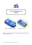
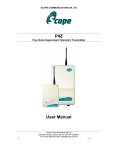
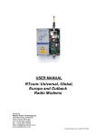
1
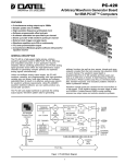
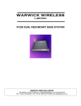
ST500 TRANSMITTER
OPERATING INSTRUCTIONS
1892 1210
These operating instructions are intended to provide the user with sufficient information to
install and operate the unit correctly.
The Wood & Douglas ST500 UHF transmitter is intended to fulfil numerous OEM
applications by virtue of its highly flexible synthesized design approach, miniature size
and cost-effective performance. The transmitter can accept analogue and digital data
input and provides an RF output power of 100mW (adjustable down to 1mW, refer to
Sales Office for details). The unit complies with MPT1329 and as such does not require
an operating licence in the UK. It is also approved to various EC specifications.
1892 1210 - ST500 Transmitter Operating Instructions- v2.12 / May 2007
1
DIMENSIONS AND FIXING
The unit is intended for PCB mounting within the customer’s equipment.
Figure 1 - ST unit dimensions and connectors
2
1892 1210 - ST500 Transmitter Operating Instructions - v2.12 / May 2007
CONNECTION
Connection to the unit is via PL1, PL2 and PL3 which plug directly into the user's own
equipment. The location of these connectors is shown in Figure 1 and detailed in the
following tables. (The unit is fitted with a 10 pin connector when parallel frequency select
facility is provided).
PIN
NAME
1
0V
2
TXE
3
FUNCTION
REMARKS
0 volts
common ground
transmit enable
o/c = transmitter disabled
LOW <+0.5V = transmitter enabled
1K nom. internal pull-up to +Vin
DIGITAL I/P
data input
0/+3V to 0/+12V, DC-coupled
4
ANALOGUE
I/P
analogue input
800 mV p-p, AC-coupled, for nominal
deviation
5
+5VOUT
+ 5 volt supply output
50mA maximum permissible current drain
6
RS232 I/P
serial programming
input
RS232 level programming input
Note: Inverted TTL data can also be used.
If not used, leave not connected, or
connect to 0V
7
0V
0 volts
common ground
8
RB1
9
RB2
10
RB3
internal pull-up to +5V, active low
parallel channel select low < 0.8V
(RB3 also readback)
high > 4.0V
Connector PL1 pin detail
PIN
NAME
FUNCTION
1
0V
2
RF O/P
3
0V
REMARKS
0 volts
common ground
RF output
50O output
0 volts
common ground
Connector PL2 pin detail
PIN
NAME
1
+VIN
2
0V
FUNCTION
REMARKS
positive supply
+6V to +15V
0 volts
common ground
Connector PL3 pin detail
1892 1210 - ST500 Transmitter Operating Instructions- v2.12 / May 2007
3
OPERATING FREQUENCIES
Each radio is made to order to cover a band (the switching bandwidth) of 5MHz within the
range 400 - 540MHz. Each radio is also manufactured to work within a particular channel
width of 12.5kHz, 20kHz or 25kHz. Within the switching bandwidth, the unit can operate
on any frequency provided it is a multiple of the channel width, and up to 128 frequencies
can be stored as numbered channels. Before the unit leaves the factory, each of the 128
channels is allocated to a frequency, but you can reprogram them if you wish.
The first 16 channels can be individually programmed, and the remaining 112 are
sequentially programmed by entering a starting frequency and a step size. The
programming is done using Wood & Douglas software (Sn00.exe) which runs on a PC
under Windows. The PC and the unit communicate via an asynchronous RS232 serial
link.
An adaptor must be used to connect the unit to the serial port of the PC and a power
supply. This also inverts the readback output of the unit and converts from TTL to RS232
levels for the PC. See the Appendix on page 13 for a suitable adaptor.
OBTAINING AND RUNNING THE PROGRAMMING SOFTWARE
1.
Download the latest version of the programming software from the Wood &
Douglas site on the internet. The URL (address) is:
www.woodanddouglas.co.uk
In case of difficulty, contact Sales at Wood & Douglas.
2.
Open the Zip file and run setup.exe, which will install the software for you.
3.
Run the Sn00.exe program. It will run in a normal window with both mouse and
keyboard support.
At this stage, the main window is displayed, similar to that shown in Figure 2.
4
1892 1210 - ST500 Transmitter Operating Instructions - v2.12 / May 2007
Figure 2 - Programming screen
The screen shows the default settings which are displayed whenever the software is run.
Greyed items are display-only, and cannot be programmed by the user.
The two tables at the left-hand side are used to set and display channel frequencies. The
top right-hand panel sets and displays general unit parameters, and the lower right-hand
panel is used to issue commands to the unit.
v
Where this manual instructs you to double-click, you can alternatively select
the item using the mouse or keyboard and then press the <enter> key.
1892 1210 - ST500 Transmitter Operating Instructions- v2.12 / May 2007
5
DESCRIPTION OF USER INTERFACE
Top Level Menu Bar (Outer Window)
File
Load Setting From Load a pre-stored set of data from a standard File Open dialog.
Save Setting To
Save the current set of data. A default name is given which you can
change, and you can navigate to the directory of your choice.
Print
Print the current set of data; only available when Report File window
is open. The currently selected Windows default printer will be used.
Exit
Exit the program. Duplicates the Exit button.
View
Main Menu
Turns on and off display of the Main Menu window.
EEPROM
This displays the contents of the units EEPROM in a separate
window. The data displayed is for the functions and channels
displayed on the main screen at that time. Data can be handmodified by highlighting the data and over-writing it. THIS SHOULD
ONLY BE CARRIED OUT WITH FULL KNOWLEDGE OF THE
INTERNAL WORKING OF THE UNIT. Note that the type of data in
each field is displayed at the bottom of the window.
While this window is displayed, no access is available to the main
window. The window must be cleared down by clearing the check
mark against it in the View menu.
View Report File
Displays a report on the current setup shown in the main menu which
can be printed if you wish.
Options
Not currently used.
(Window List)
Shows windows which can currently be displayed. When the
EEPROM window is displayed, Main Menu is removed from this list.
Unit Setup
Serial port
COM Port:
Osc Freq
Displays the oscillator frequency, which is fixed by the
hardware and cannot be changed.
6
Select the serial port for the connection to the
unit, default COM1. Unavailable options are
greyed.
Baud Rate: Select the baud rate for communications with the
unit Unavailable options are greyed.
1892 1210 - ST500 Transmitter Operating Instructions - v2.12 / May 2007
Comparison Freq. (Fc)
Fixed by the hardware. Channel spacing can be set to an
integer multiple of this value by setting Table Step Size
accordingly. For example, a Table Step Size of 2 sets Fc to
25kHz if Osc Freq is 12.5kHz.
Intermediate Frequency
Displays High Side/Low Side and the Intermediate Frequency,
which is fixed by the hardware and cannot be changed.
PIC Code
Only displayed when the Readback function has been used to
download the contents of the unit EEPROM. Otherwise shows
"Code unknown, Ver. unknown".
Help
Help Instructions
Displays a window containing instructions for mouse and keyboard
use.
About
Displays information about the program and Wood & Douglas,
including website and agent details.
Main Menu Window
Individual Channel Table
The top left pane of the main window, marked Random Channel Table, contains the first
24 channels (0-23), which can be individually set.
Sequential Channel Table
The lower left pane of the main window contains the remainder of the channels. Since
these are set as a block, entry fields are provided below the list to define the starting
frequency and the step (spacing between channels).
Current Settings
The top right pane of the main window contains a number of parameters, most of which
are display-only.
Note: The unit has an operating frequency range (switching bandwidth) of about 5MHz.
Where this band lies in the RF spectrum is determined by the physical build of the
unit and how it has been aligned. If a frequency outside the alignment band is
selected then the operation of the unit will no longer be to the stated specification.
Minimum Frequency
The software will not allow a channel to be set to a frequency
below this minimum. This frequency is stored in the nonvolatile EEPROM in the unit.
Maximum Frequency
The software assumes a 5MHz switching bandwidth to
calculate the Maximum Frequency from the Minimum
Frequency and uses this to calculate the frequencies in the
1892 1210 - ST500 Transmitter Operating Instructions- v2.12 / May 2007
7
drop-down list displayed when selecting channel frequencies.
Receiver Offset
The SX500 normally operates with identical transmit and
receive frequencies. This parameter allows a positive or
negative offset to be added to the receive frequency. Note that
this does not change the RX switching bandwidth, and that the
actual receive frequencies programmed into channels must still
fall within it.
Max. Channel Number
This number will determine how many channels are
programmed and may be selected during operation.
Serial/Parallel
This should be regarded as display-only. When the Set
Parallel Ch Mode or Program Serial Channel commands are
issued, this item will be set to Parallel or Serial respectively.
Serial Channel No.
The channel number to which the unit will be set when the
Program Serial Channel command is issued.
Unit Programming Commands
Four commands can be issued by double-clicking their names in the list in the bottom
right pane of the main window.
Set Parallel Ch Mode
Sets the unit to Parallel channel mode, such that the operating
channel (channels 0-7 only) is defined by the binary number
represented by three wires carrying logic levels. If no logic
inputs are connected, the unit defaults to channel 0.
This must be the last (serial) command issued before the unit
is disconnected from the computer, as any further serial
communication will reset the unit to Serial mode.
Read from Unit
Reads data from the unit into the program, which is then
displayed on the screen. Until this command has been
issued, no data can be downloaded to the unit.
Program Unit
Downloads data from the program to the unit. This command
can only be issued after a Read from Unit command has been
issued during the current session.
Program Serial Channel
Sets the unit to the channel defined as Serial Channel No, and
leaves the unit in Serial channel selection mode.
8
1892 1210 - ST500 Transmitter Operating Instructions - v2.12 / May 2007
PROGRAMMING THE UNIT
Three steps are necessary:
v
v
v
Upload values from the unit
Edit the values
Download values to the unit
Uploading Current Unit Settings
First, you must read into the computer what is in the unit’s memory at present. To do this,
issue the Read From Unit command by double-clicking over it. The data replaces the
defaults on the screen.
v
The program insists that you do this before allowing you to reprogram the
unit to make it less likely that inappropriate values be entered.
v
However, once you have uploaded during a session, you may edit and
download the data to as many units as you wish.
Programming Individual Channels (0-23)
The first 24 channels (0-23), which can be individually set, are displayed and set in the
top left panel of the window. To set the frequency of one them:
1.
2.
3.
4.
Ensure that the ‘Random’ checkbox is selected
Double-click over that channel
From the resulting list, select the frequency in MHz
Click on OK.
v
The entered value must be an integer multiple of the Comparison Frequency
shown at the top right of the screen, otherwise an error message is
displayed.
v
The values offered are within the switching bandwidth of your unit, to
safeguard you from inserting an inappropriate value.
To set the frequency of all of the first 24 channels at once,
1.
2.
3.
4.
5.
6.
7.
Ensure that the Table checkbox is selected
Double-click over any channel
In the resulting dialog, click the drop-down arrow to the right of Table Start
Select the start frequency in MHz from the list
Click the drop-down arrow to the right of Table Step
Select an integer multiple of the Comparison Frequency from the list
v
For example, if the Comparison Frequency is 12.5kHz, enter 2 for a spacing
of 25kHz.
Click on OK.
1892 1210 - ST500 Transmitter Operating Instructions- v2.12 / May 2007
9
Programming Sequential (Table or Block) Channels (24-255)
Channels 24-255, whose frequencies are set sequentially by providing a starting
frequency and a spacing, are displayed and set in the lower left panel of the window. To
set their frequencies, which can only be done as a single block:
1.
2.
3.
4.
Click the drop-down arrow to the right of Table Start
Select the start frequency in MHz from the list
Click the drop-down arrow to the right of Table Step
Select an integer multiple of the Comparison Frequency from the list
v
For example, if the Comparison Frequency is 12.5kHz, enter 2 for a spacing
of 25kHz.
Downloading New Settings to Unit
As yet, the settings have only been edited in the SXn00 program. To download them to
the unit, double-click on Program Unit in the lower left panel.
v
This is only permitted if the Read from Unit command was previously used to
upload settings at some point during the session.
Channel Selection Mode
Having programmed frequencies into the channels, you can specify which channel to use
(channels 0-255) or that the channel will be selected by parallel logic levels (channels 0-7
only).
The unit defaults to serial channel selection whenever it has serial communications, which
includes whenever the SXn00 software communicates with it.
To select serial control, and a channel from 0-255 (which will be used until further
commands are received), type the number into Serial Channel No in the top right-hand
panel, then double-click Program Serial Channel in the lower right-hand panel.
v
The Serial/Parallel setting makes no difference, but is changed to "Serial" if
necessary.
v
The channel command is sent to the unit and becomes operative
immediately.
To enable parallel channel selection mode, double-click Set Parallel Ch. Mode in the
lower right-hand panel.
10
v
The Serial/Parallel setting makes no difference, but is changed to "Parallel"
if necessary.
v
The command is sent to the unit and becomes operative immediately. The
channel number is unknown, because it depends on the logic levels applied
to three inputs as described on page 5. Serial Channel Number should be
ignored.
1892 1210 - ST500 Transmitter Operating Instructions - v2.12 / May 2007
Parallel channel mode select must be the last action before disconnecting the unit: any
further serial communication will reset it to serial mode.
Completing Programming
This completes programming and the unit may be disconnected. It is not necessary to
switch off power or stop the program first.
Programming Further Units
Further units may be programmed by disconnecting one unit and connecting the next,
which may be done without switching the power off.
v
If you want to use the channel frequency settings from the previous unit,
either as they are or as a basis for editing, do not stop the program, because
it does not save settings between sessions.
Proceed as above, using Program Unit when all the channel parameters are correct, and
selecting Program Serial Channel or Set Parallel Channel Mode before disconnecting the
unit.
1892 1210 - ST500 Transmitter Operating Instructions- v2.12 / May 2007
11
CHANNEL SELECTION DURING OPERATION
There are three ways to select a channel during operation:
v
v
v
In hardware, using three logic lines to select channels 0-7
Using the SXn00.exe software and a serial connection from a PC to the unit
By sending a short serial data message to the unit from your own equipment.
Parallel Channel Selection
v
The unit must have been left in parallel mode when it was programmed.
v
Only channels 0 - 7 are available in this mode
The channel in use depends on the logic levels supplied to PL3 pins 11 to 13, as set out
in the table below. If no connections are made, the unit defaults to channel 0.
CHANNEL SELECTION
PIN 13 (RB3)
PIN 12 (RB2)
PIN 11 (RB1)
CHANNEL
LOW
LOW
LOW
7
LOW
LOW
HIGH
6
LOW
HIGH
LOW
5
LOW
HIGH
HIGH
4
HIGH
LOW
LOW
3
HIGH
LOW
HIGH
2
HIGH
HIGH
LOW
1
HIGH
HIGH
HIGH
0
The logic levels are :
LOW < 0.8V
HIGH > 2V or floating
Serial Channel Selection (using SXn00.exe)
If the unit was programmed for serial channel selection, it will operate on the channel
nominated at that time. This setting is remembered during unit power off.
The channel can be changed by entering a serial channel number and issuing the
Program Serial Channel command whenever the PC is connected to the unit.
By making up a special adaptor, the PC could be connected to the unit in situ while it is
operating.
12
1892 1210 - ST500 Transmitter Operating Instructions - v2.12 / May 2007
Serial Channel Selection (own equipment)
If you want to select a channel using serial mode from your own equipment rather than
using the supplied software, then you must use this protocol:
1200 baud, RS232 levels, 1 start bit - 8 bit data - no parity - 1 stop bit
and send the following data sequence to the RS232 input, allowing at least 5ms between
the characters in the data stream:
x40 (decimal 64) synchronising code
Channel number in hex (decimal 0 to 255)
x95 (decimal 149) confirmation byte
Any channel between 0 and 255 can be selected.
v
Any serial communication with the unit disables parallel selection.
1892 1210 - ST500 Transmitter Operating Instructions- v2.12 / May 2007
13
RANGE INFORMATION
The following table gives an indication of the typical ranges to be expected between a
transmitter and receiver that have simple end-fed dipole antennas.
The following assumptions have been made in the calculations:
line-of-sight between antennas
0dB gain for the transmitter and receiver antennas
0dB loss for connectors and cables between the antenna and the radio connector
20dB fade and environmental margin
-100dBm received signal strength, allowing for digital and analogue signals
Range versus TX power
14
Frequency (MHz)
Power (mW)
Power (dBm)
Range (km)
458.5
1mW
0
0.5
458.5
10mW
10
1.7
458.5
100mW
20
5.3
458.5
500mW
27
11.9
1892 1210 - ST500 Transmitter Operating Instructions - v2.12 / May 2007
TECHNICAL SPECIFICATION
Frequency range
:
Switching bandwidth
Frequency stability
Number of RF channels
:
:
:
RF channel selection:
:
RF output power into 50O
:
:
:
:
Adjacent channel power
TX switching time
Modulation input
analogue
:
digital
:
Frequency response
:
Deviation
25kHz channel spacing :
20kHz channel spacing :
12.5kHz channel spacing :
Channel switching delay
:
Channel spacing
:
Modulation type
:
Spurious emissions
(conducted & radiated)
:
Supply voltage
:
Supply current at 7.2V
:
Interface connections
:
RF connection
:
Operating temperature
:
Storage temperature
:
Size overall
:
Weight
:
Type approval
:
General facilities
:
:
:
Switching bandwidth between 400 to 540MHz to
order
5MHz
+2ppm
up to 128, frequencies programmable within
switching bandwidth (16 individually, 112 sequential
table) using supplied software
1 of 128 serial select (1200 baud RS232)
1 of 8 3-wire parallel select
100mW adjustable to 5mW
1 - 10mW version available
<200nW (-37dBm)
<60ms
200mV to 5V p-p AC coupled
+3 to 12V square wave DC coupled
20Hz to 3kHz at -3dB. (GMSK version available)
+3kHz nom (+5kHz max)
+2.3kHz nom (+4kHz max)
+1.5kHz nom (+2.5kHz max)
<50ms across switching bandwidth
12.5kHz/20kHz/25kHz available
F1D/F2D/F3D
in accordance with R&TTE directive
6 - 15V DC negative earth
<100mA for 100mW output
0.1" header
3 pin 0.1" header
-20%C to +55%C
-30%C to +70%C
60 x 39 x 15 mm (2.36 x 1.53 x 0.59 inches)
35g
designed to meet ETS 300/220 and MPT 1329
+5V output
analogue and digital inputs
direct TT500 replacement
1892 1210 - ST500 Transmitter Operating Instructions- v2.12 / May 2007
15
APPENDIX: TTL TO RS232 ADAPTOR
Many PCs do not require true RS232, and will work with the simple adaptor of Figure 3.
The transistor used must have a gain of at least 30.
Figure 3 - Simple programming adaptor
Figure 4 shows the circuit of an adaptor providing true RS232 for readback when
programming a unit.
Figure 4 - Programming adaptor (True RS232)
16
1892 1210 - ST500 Transmitter Operating Instructions - v2.12 / May 2007
A suitable inverting TTL to RS232 buffer circuit using the industry-standard MAX232 part
is shown in Figure 5.
Figure 5 - Suggested RS232 buffer circuit
The MAX232 is obtainable from many component suppliers, e.g. RS Components stock
no. 655-290.
Wood & Douglas Ltd, Lattice House
Baughurst, Tadley, Hants, RG26 5LP
Tel:+44 (0)118 981 1444 Fax: +44 (0)118 981 1567
email: [email protected]
website: www.woodanddouglas.co.uk
1892 1210 - ST500 Transmitter Operating Instructions - v2.12 / May 2007
© Wood & Douglas Ltd 2007
17