1
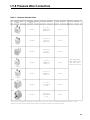
I-T-E Pressure Wire Connectors
E.
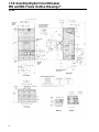
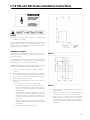
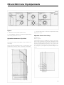
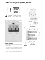
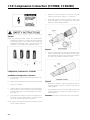
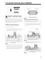
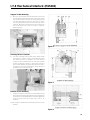
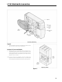
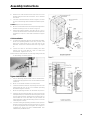
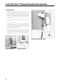
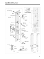
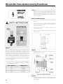
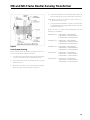
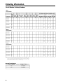
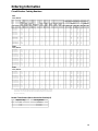
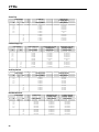
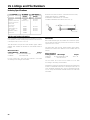
Attach power cables to connectors and tighten set
screws (5) (Figure 1) to specifications per Table 1.
NOTE: Cables must extend straight for at least 4 inches from
face of connector to clear shield.
F
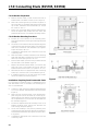
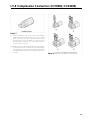
Mount removable terminal shield (6) (Figure 2) to end of
circuit breaker. Shield should be flush with end of circuit
breaker.
G. Re-assemble terminal shield.
NOTE: When terminal cover is properly installed, wire connector shield should be held securely.
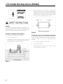
General
NOTE: This instruction outlines the recommended installation
procedure for all MD and ND Frame pressure wire
connectors.
A.
Move breaker handle to OFF position, or depress PUSH
TO TRIP button. Breaker must be in OFF or TRIPPED
position before continuing.
B.
Remove terminal shield (1) (Figure 2) (two #6-32 screws.)
C.
Mount breaker securely. See circuit breaker instructions
for proper installation procedures.
D.
Mount pressure wire connectors (2) to terminal pads (3)
with mounting screws (4) (Figure 1). Recommended
torque is 228 in. Ib.
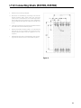
NOTE: End barrier NDTS is supplied with kits 2 TA4P8500,
3TA4P8500, 2TA3P8750, 3TA3P8750, 2TA2K8750,
3TA2K8750. Barrier can be purchased as a separate
item for use with other terminal connectors.
NOTE: Steps C and D may be completed in any convenient
order.
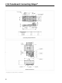
Figure 2
Figure 1
22