1
BEVEL ANGLES (00 AND 450)
00 Bevel Stop Adjustment
•
•
•
Fig. 6
•
•
•
•
•
•
•
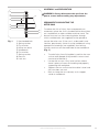
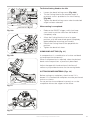
Ensure that the Cutting Head is in the locked
down position with the latching pin fully engaged
in its socket. (see Fig.6)
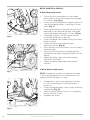
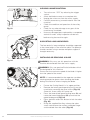
Ensure that the Cutting Head is upright, against its
stop and the bevel pointer is indicating 00 on the
scale. (Fig. 7)
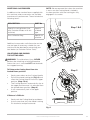
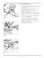
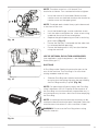
Place the Set Square on the table with one short
edge against the table and the other short edge
against the blade (avoiding the TCT tips). (Fig. 8)
If the blade is blade is not 900 square with the
mitre table adjustment is required.
Loosen the Bevel Lock Handle and tilt the Cutting
Head to the left.
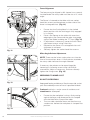
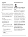
Loosen the locknut on the Bevel Angle
Adjustment Screw. (Fig. 9)
Use a Hex Key to turn the screw in or out to adjust
the blade angle.
Return the Cutting Head to its upright position
and recheck the angular alignment against the Set
Square.
Repeat the above steps until correct angular
alignment is achieved.
Tighten the Bevel Angle Adjustment locknut
securely.
•
00 Bevel Pointer Adjustment
Fig. 7
NOTE: The operator must be satisfied that the blade
is set exactly perpendicular to the table when in the
upright position and against its stop.
•
•
•
•
If the pointer is not in exact alignment with the
00 mark on the protractor scale adjustment is
necessary.
Loosen the Bevel Pointer screw using a #2 Phillips
screwdriver. (Fig. 10)
Adjust the Bevel Pointer so that it is in alignment
exactly with the 00 mark.
Retighten the screw.
Fig. 8
16
www.evolutionpowertools.com