1
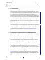
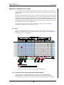
TD 92422GB
System Planning
Ascom IP-DECT System
18 February 2010 / Ver. E
System Planning
Ascom IP-DECT System
TD 92422GB
Contents
1 Introduction............................................................................................................. 1
1.1 Abbreviations ..................................................................................................... 1
1.2 Glossary ............................................................................................................. 1
2 Wired LAN/Backbone Requirement ....................................................................... 3
2.1 End-to-End QoS ................................................................................................. 3
3 Base Station Planning ............................................................................................. 4
4 Client’s Requirements ............................................................................................. 5
5 Traffic Capacity of the System................................................................................ 6
Example: .................................................................................................. 7
5.1 Traffic Capacity of the Base Stations ................................................................... 7
Example: .................................................................................................. 7
6 Base Station Coverage............................................................................................ 8
6.1 Architecture ....................................................................................................... 8
6.2 Building Elements .............................................................................................. 9
6.2.1 Walls ......................................................................................................... 9
6.2.2 Ceilings and Floors ..................................................................................... 9
6.2.3 Fire-resistant walls/doors .......................................................................... 10
6.3 Special Areas ................................................................................................... 10
6.3.1 Outdoors/car park .................................................................................... 10
6.3.2 Lift ........................................................................................................... 11
6.3.3 Stairwell ................................................................................................... 11
6.3.4 Toilet Rooms ............................................................................................ 11
6.3.5 Maintenance Shaft ................................................................................... 11
6.3.6 Basement and Indoor Car Park ................................................................. 11
6.4 Reflective Environment ..................................................................................... 12
6.4.1 Time Delay Spread ................................................................................... 12
6.4.2 How to Identify Reflective Environment .................................................... 13
6.4.3 Locations for Base Stations in Reflective Environment ............................... 13
6.4.4 Customer Acceptance .............................................................................. 13
7 Synchronization .................................................................................................... 14
7.1 Air Synchronization .......................................................................................... 14
7.2 Considerations for Air Synchronization at a Multiple Building Site .................... 14
7.2.1 In systems where handover is required between buildings ........................ 14
When there is good coverage between buildings .................................... 14
When there is poor coverage between buildings ..................................... 14
18 February 2010 / Ver. E
System Planning
Ascom IP-DECT System
TD 92422GB
7.2.2 In systems where only roaming is required between buildings .................. 16
7.3 Sync Slave IPBS ................................................................................................ 16
7.4 Sync Master IPBS .............................................................................................. 17
7.5 Standby Sync Master IPBS ................................................................................ 17
7.6 Ring Synchronization ....................................................................................... 17
Redundant ring synchronization .............................................................. 18
Non redundant ring synchronization ....................................................... 18
Reference synchronization ...................................................................... 19
8 Site Survey with IPBS Base Station...................................................................... 20
8.1 Start by placing two base stations in the site .................................................... 20
8.2 Check the speech coverage for base station A ................................................. 21
8.3 Check the synchronization coverage ................................................................ 21
8.4 To perform measurements for other base stations ............................................ 22
9 Location of the Base Stations............................................................................... 23
9.1 LAN Access ...................................................................................................... 23
9.2 Power the Base Stations ................................................................................... 23
9.3 Antennas ......................................................................................................... 23
9.3.1 Internal and External Antennas ................................................................ 23
9.3.2 Directional Antennas ................................................................................ 24
9.4 Base Station Planning Tips ................................................................................ 25
10 Making a Base Station Plan................................................................................ 26
10.1 Finalizing the plan .......................................................................................... 27
11 Multiple Master Systems .................................................................................... 28
11.1 Why Multiple Master Systems ........................................................................ 28
11.1.1 System Capacity ..................................................................................... 28
12 Related Documents ............................................................................................. 29
Document History ........................................................................................................ 30
Appendix A: Multiple DECT Systems ...................................................................... 31
18 February 2010 / Ver. E
System Planning
Ascom IP-DECT System
1
TD 92422GB
Introduction
This document gives a description on how to plan the Ascom IP-DECT system. The Ascom
IP-DECT system is an IP based cordless telephony and messaging system for connection to
private telephone exchanges.
The Ascom IP-DECT system supports the DECT standard which gives a full integration of
messaging and voice functions. The Ascom IP-DECT system can be integrated with
external applications such as different alarm systems, networks and e-mail. This gives
features such as; messages to handset, alarm from handset, message acknowledgement,
and absent handling.
1.1
1.2
Abbreviations
DECT
Digital Enhanced Cordless Telecommunications:
global standard for cordless telecommunication.
GoS
Grade of Services:
IP
Internet Protocol:
global standard that defines how to send data from one computer to
another through the Internet
IPBS
IP-DECT Base Station
IPBL
IP-DECT Gateway
LAN
Local Area Network:
a group of computers and associated devices that share a common
communication line.
PBX
Private Branch Exchange:
telephone system within an enterprise that switches calls between local
lines and allows all users to share a certain number of external lines.
RFP
Radio Fixed Part. DECT base station part of the DECT Infrastructure.
Legacy DECT base station connected to an IPBL or the local RFP part in an
IPBS.
QoS
Quality of Service
VoIP
Voice over Internet Protocol
Glossary
Cell
A cell is the radio coverage area of a base station.
Roaming
The procedure of moving the Portable Device from one IPBS/IPBL to
another and still be able to place outgoing and receive incoming calls.
External
Handover
The procedure of moving an active call from one IPBS/IPBL to another.
System ID
System ID in the Pari Master defines the sync domain and handover
domain. Within the coverage area, the System ID must be unique from
other Ascom IP-DECT systems.
Master ID
Master ID must be unique for each Master in a system. The Standby
Master must have the same id as the Master.
RFPI
The RFPI, Radio Fixed Part Identity, is the broadcast identity which uniquely
identifies a RFP geographically.
18 February 2010 / Ver. E
1
System Planning
Ascom IP-DECT System
TD 92422GB
SARI
The SARI, Secondary Access Rights Identity, is the broadcast identity which
uniquely identifies an Ascom IP-DECT system.
Cover
Radius
The radius of the circle (circular radiation patterns of the base station
antennas are assumed), around a particular base station, in which portable
parts can communicate with that base station.
Sync Radius The radius of the circle, around a particular base station, in which other
Base Stations may synchronize with that Base Station.
Sync
Coverage
A sync coverage is the air sync coverage areas for all base stations
connected to the same sync Master.
Sync
Domain
Sync domain defines the Radios to which automatic synchronization is
allowed. Sync domain is defined by the System ID. A sync domain can
consist of several sync coverage areas where each synch coverage has its
own sync Master.
Handover
Domain
Handover domain defines the Radios to which external handover is
allowed. Handover domain is defined by the System ID.
18 February 2010 / Ver. E
2
System Planning
Ascom IP-DECT System
2
TD 92422GB
Wired LAN/Backbone Requirement
It is highly recommended that a Network Assessment of the LAN is carried out before an
installation or when new applications and/or user density is added to secure the voice
quality.
There are several things to consider when designing a network:
• In order to achieve optimal performance the infrastructure should be connected to a
switched network (no hubs or repeaters).
• When setting up a network supporting both voice and data it is recommended that
voice and data are separated on different VLANs.
• Maximum capacity of the VoIP traffic may not exceed 25% of the capacity of the
network.
• Maximum capacity of the network may not exceed 75% of the total capacity of the
network, including the VoIP traffic.
• No firewalls should be used in the network. If they are anyway, tunneling or application
aware firewalls should be used.
• Depending on network size, a backbone of at least 100 Mbps should be used.
Figure 1.
In a switched network the transmission delay should not be an issue but if voice traffic is
routed a significant transmission delay could be added. If the transmission delay is too
long an echo will appear in the voice path impacting the systems voice quality. The
transmission delay will also add to the speech delay.
Jitter in voice packages will also add to the speech delay since the IPBS/IPBL will adjust the
jitter buffer size.
Note: There are several tools from third-party vendors that is used to provide detailed and
useful information when performing site surveys.
2.1
End-to-End QoS
To achieve QoS for a phone call, it is important that QoS is enabled or managed all the
way between the two end points. By following a speech packet as it travels along the path
between the end points, it is possible to identify all network segments and transitions
where QoS needs to be managed.
18 February 2010 / Ver. E
3
System Planning
Ascom IP-DECT System
3
TD 92422GB
Base Station Planning
The major task in installing an Ascom IP-DECT system is defining the number of base
stations required to cover an area to a satisfactory level. This chapter describes how a base
station planning can be made in order to gain full area coverage.
Small sites usually have a homogeneous layout, it is therefore easy to predict the field
pattern of the base station which makes the planning relatively easy. The larger the site,
the more complex the site survey becomes. Since a larger site often is less homogenous
the base station placing will be more difficult. Generally the client has particular
requirements which have to be considered, these requirements can be coverage in a lift,
underground car park, conference rooms, outdoors and so on.
The steps in base station planning are as follows:
1
Find out the client specific requirements, see 4 Client’s Requirements on page 5 and
5 Traffic Capacity of the System on page 6.
2
Determine the average cell size, see 6 Base Station Coverage on page 8 and 8 Site
Survey with IPBS Base Station on page 20.
3
Decide base station positions, see 9 Location of the Base Stations on page 23.
4
Make a base station plan, see 10 Making a Base Station Plan on page 26.
5
Perform a site survey to confirm that speech and air sync coverage is as expected.
18 February 2010 / Ver. E
4
System Planning
Ascom IP-DECT System
4
TD 92422GB
Client’s Requirements
The most important thing when planning an Ascom IP-DECT system is that the system
meets the needs and requirements of the customer. Discuss with the customer where high
quality is of absolute necessity and whether there are areas where it is sufficient for people
to be available but with lower sound quality, for example outdoors or in a production hall.
Also discuss whether special areas such as lifts, stairwells, basements, indoor car parks,
toilets, maintenance shafts, and so on should be covered.
In some areas and departments, for example: sales, purchase, technical support
departments, canteens, a higher traffic capacity is needed. Consequentially these areas
requires additional base stations, see 5 Traffic Capacity of the System on page 6 for
information how to calculate traffic capacity. Discuss with the customer where a higher
traffic capacity is needed.
18 February 2010 / Ver. E
5
System Planning
Ascom IP-DECT System
5
TD 92422GB
Traffic Capacity of the System
The traffic capacity of the Ascom IP-DECT system is mainly determined by the number of
base stations and in exceptional cases also by the LAN bandwidth. A single base station
has a capacity of 8 simultaneous calls and a single gateway has a capacity of 40
simultaneous calls.
The traffic capacity of the Ascom IP-DECT system is determined by:
• Grade Of Service (GOS) accepted by the customer.
• Number of speech circuits available - 8 per IPBS/RFP, 40 per IPBL.
The grade of service is the probability that a call cannot be made because of congestion in
the system. The customer has to indicate which grade of service is acceptable. A grade of
service of 1%, or 0.01, means an average of 1 lost call in every 100 calls.
The two parameters mentioned above (GOS and number of speech circuits) and the total
amount of traffic (erlang) that is required, are related to each other. The table below
shows an except of these relations. Practically, this table is used to calculate from a given
GOS and erlang value the number of base stations needed. The erlang value is the total
traffic generated by all cordless phone users.
A base station provide for 8 speech circuits. The IPBL handle a maximum of 40.
Figure 2. .
Number
of base
stations
Speech
circuits
1
Grade Of Service (GOS)
2%
1%
0.5%
0.1%
8
3.6
3.2
2.7
2.1
2
16
9.8
8.9
8.1
6.7
3
24
16.6
15.3
14.2
12.2
4
32
23.8
22.1
20.6
18.2
5
40
31.0
29.0
27.3
24.5
6
48
38.4
36.1
34.2
30.9
7
56
45.9
43.3
41.2
37.5
8
64
53.4
50.6
48.3
44.2
The table below shows what erlang values practically mean in call-minutes for a cordless
phone.
Figure 3.
mE
Minutes per hour mE
Minutes per hour
50
100
150
200
3
6
9
12
15
18
30
45
18 February 2010 / Ver. E
250
300
500
750
6
System Planning
Ascom IP-DECT System
TD 92422GB
Example:
A customer ordering a system with 55 cordless phones, generating 200 mE each in
average, requires a system with a traffic capacity of 11 E. With an accepted GOS of 0.5%
the number of base stations is found as follows:
The total traffic is 11 E. In the column of 0.5% GOS, the next higher value of 11 E is 14.2
E, resulting in 3 base stations. The system shall be equipped with 3 base stations, offering
the client 14.4 E instead of 11. This means that the system has an over-capacity 3.2 E,
which allows expansion of the system with 16 cordless phones without reducing the grade
of service or the need of more base stations.
5.1
Traffic Capacity of the Base Stations
The total traffic that is being generated by all cordless phones of the systems should be in
accordance with the capacity of the cordless network as well. A base station, having 8
channels available, has an erlang value of 2.7 with a GOS of 0.5%. This value can be read
from the table above. This means that each base station can serve 18 cordless phones,
assuming that cordless phones generate 150 mE each during busy hour, (13.5 cordless
phones if 200 mE each).
Example:
Suppose that in the building of the customer in the example in 5 Traffic Capacity of the
System, full coverage can be achieved by 4 base stations. This means that all cordless
phones generate together 55 x 0.200 = 11 E, while the base stations traffic capacity is
only 4 x 2.7 = 10.8 erlang. This is too little. This discrepancy can be solved by adding
another base station nearby the busiest part of the company.
Practically, the total capacity offered by the cordless network is generally more than
sufficient, but this is from an average point of view. On certain places, traffic demands
may vary such that locally the network is often blocking, or has a lower GOS than
required. For instance a purchase department may easily generate 300 mE per cordless
phone during busy hour, thus, when e.g. with 6 persons giving a very high load on the
base station close by. It may be necessary to add a base station in this area to have enough
capacity for others to call as well. Also think of e.g. canteens during lunch time etc.
18 February 2010 / Ver. E
7
System Planning
Ascom IP-DECT System
6
TD 92422GB
Base Station Coverage
This section describes how architecture, building elements, and special areas affect the
coverage and the placing of the base stations.
The radio environment or the cell that is covered by a base station is not of a spherical
shape as often suggested in figures. If a snapshot could be taken of its form, it would
become clear that its shape is much more irregular. The momentary size and shape are
dependant on the material of which walls and floors are made, the position and material
of furniture, machines, air-conditioning and the position of the base station in such an
environment. Because of these unpredictable conditions it is not possible to give any hard
rules on calculating the number of base stations in a given situation.
• The in-house cell size in offices can have a radius of between 10 and 30 metres, see
figure 1 on page 8. The cell size in exhibition or production halls can have a radius of
up to 200 metres.
• The free space (outdoors) cell radius can be up to 300 metres.
• Base stations may partially cover the floors immediately above and below. The useful
range through floors and ceiling varies between 0 and 8 m (2 floors) radius; see figure
1 on page 8.
6.1
Architecture
This section describes how the architecture of the building can affect the coverage.
• Central areas giving access to stairs and lifts may require extra base stations due to
heavier constructions.
• Coverage in lifts may require base stations closer to or in the lift shaft.
• Corners and irregularities in the construction such as partial renovation, extensions of
older buildings, and so on have influence.
• Concentration of air-conditioning ducts or other technical installations may influence
the field pattern and thus the coverage.
40 metres
Base station 1
Base station 2
3.5 metres
Base station 3
Front view of a building
Conference
room
Office
16 metres
Corridor
Office
006
Pantry
Base
station 1
Top view of top floor
Figure 1. Example of the locations of base stations in a building.
18 February 2010 / Ver. E
8
System Planning
Ascom IP-DECT System
6.2
TD 92422GB
Building Elements
This section describes how different building elements can affect the coverage.
• The cell size is dependant on the material of which walls, ceilings and floors are made.
• Plain, light or reinforced concrete, wood and plaster absorb and pass radio waves in
different ways.
• Metal walls and large metal cabinet rows reflect all signals, resulting in a greatly
reduced coverage in areas behind these objects.
• X-ray rooms in hospitals protected by lead walls and computer rooms in banking
buildings protected against unwanted interference do not allow radio signals to enter.
• Exhibition halls or production halls may give reflections due to large metal structures.
This causes interference which reduces the capacity and coverage range of the base
station.
6.2.1
Walls
Walls, ceilings and floors have large impact of the coverage range, different types of walls
have different impact on the signal range. For list of the most common types and the
approximate range achieved through these materials, see the table below.
Type
Examples
Range in
metres
Stud wall
Plaster
30-60
Concrete
Reinforced
concrete
10-30
Fire wall
Stone/brick
Metal
0-10
30-50
A panel on brickwork.
Wood
0-10
30-60
Wired glass
Fire protection.
0-10
Surface coated
float glass
Only of importance for coverage
outside if the base station is installed
inside.
30-50
None
Open-plan office or outdoors.
150-300
Note: The values in this table are estimated values. Furniture (cupboards etc.), and the
amount of movement in the area to be covered, for example, cranes in a production hall
(see also 6.4 Reflective Environment on page 12) are further factors that affect the
coverage range.
6.2.2
Ceilings and Floors
The difference between ceilings and floors compared to walls lies in the materials used.
Concrete and reinforced concrete are the main materials and it is important to determine
the level of coverage of a base station on the floor above and below. For ‘normal’ concrete
this coverage extends to a radius of approximately 15-20 metres which provides coverage
for the floors below and above. An open stairwell or an atrium can in some cases be used
to provide coverage to two floors at the same time, see figure 2.
18 February 2010 / Ver. E
9
System Planning
Ascom IP-DECT System
TD 92422GB
2nd floor
Open stairwell
or atrium
007
1st floor
Figure 2. Base station covering two floors
6.2.3
Fire-resistant walls/doors
The same facts applies for fire walls as for normal walls mentioned in the section above.
However, fire doors are usually open during the site survey, it is important to close the fire
doors before doing the final site survey measurement and before finalising the base
station plan. Should a fire break out and the doors then be closed, there must of course
still be sufficient coverage.
6.3
Special Areas
This section describes a number of special areas which must be considered when doing a
base station planning, and how to ensure full DECT coverage in these areas.
6.3.1
Outdoors/car park
Coverage outdoors is usually not a problem since there are few or no obstacles. The base
station location depends on the client and on the size of the area to be covered. If the
client wishes to have as few base stations as possible installed outside (because of the
costs of the outdoor housing), it is possible to install one or more base stations with the
antennas in front of a window.
The base station must be able to ‘see’ as much as possible of the outdoor area to be
covered (that is, there must be as few obstacles as possible between the base station and
the covered area). Ensure that a measurement is carried out in order to check how much
coverage a base station provides to the outdoor area, the intention is not to install all the
base stations in front of windows, since this is not the ideally position to provide indoor
coverage (normally 1-2 base stations are sufficient).
Type of glass
Range in
metres
Normal glass
150-300
Surface coated 30-50
float glass
Wired glass
(fine-mesh)
18 February 2010 / Ver. E
0-20
10
System Planning
Ascom IP-DECT System
6.3.2
TD 92422GB
Lift
If coverage in lifts are desired, locate the base station close to the lift, preferably at the
front in a way that the base station can ‘see’ the front1. This is because a lift is usually
surrounded on three sides by a reinforced lift shaft, with the only opening being at the
front. Locating a base station in front of a lift is usually not the most ideal position for the
planning as a whole. It is usually the case that one or more extra base stations will be
required to provide coverage for a lift. The base station will generally also provide
coverage for the storey above and below the floor on which it is installed.
6.3.3
Stairwell
The major problem with stairwells is that they are often sited in a corner of the building.
Coverage is not a problem in itself, but it must be seen in the context of the overall
planning. There are various ways of providing coverage for a stairwell. Either the base
station is installed directly in the stairwell as a dedicated base station for the stairwell, or it
is installed in the close vicinity of a stairwell. The method depends on the type and location
of the stairwell (is it an open or closed stairwell; is it sited in a corner of the building or in
the centre and so on).
6.3.4
Toilet Rooms
Toilet rooms are generally in awkward positions for a site survey: behind or next to lifts, in
or next to stairwells or in a corner of the building. A base station installation in the toilet
room itself can be considered. If placed outside the toilet room it should be placed in the
vicinity of the toilet room in a location where the base station can ‘see’ as much as
possible of the toilet room (preferably the entrance because doors are generally made of
wood and these damp the signal less than the walls).
If the base station is placed in the vicinity of the toilet room, locate it in a way that it
provides coverage for as much of the rest of the floor as possible.
6.3.5
Maintenance Shaft
In larger buildings there is usually the requirement that coverage also be provided in
maintenance rooms. The most common are the rooms for the lift and ventilation system.
The lift maintenance room is often on the roof or in the basement. The ventilation
maintenance room is usually on the roof. Do not omit these rooms they should be
discussed with the client to avoid the client being faced with surprises. A well-positioned
base station on the top floor (20 to 30 metres at most from the room where coverage is
required) usually provides sufficient coverage for the maintenance rooms on the roof.
6.3.6
Basement and Indoor Car Park
It can be difficult to provide sufficient coverage in basements and indoor car parks due to
the usually heavy constructions.
1. ‘see’: there are as few obstacles as possible such as walls etc. between the base station and the lift.
18 February 2010 / Ver. E
11
System Planning
Ascom IP-DECT System
6.4
TD 92422GB
Reflective Environment
When providing coverage in a metal hall (for example, a production hall or storage
building), there are a number of issues which call for additional attention. The dimensions
of the hall and the material used (metal, concrete, brick etc.) are important deciding
factors in the hall’s radio reception. Every hall is different, and it is very difficult to predict
the radio reception. Check carefully, therefore, whether the walls are made of metal, what
the hall’s dimensions are, whether the roof is reflective, what is contained in the hall, and
whether objects in the hall are stationary or constantly moving.
In the case of poor speech quality in a metal hall, this can be attributed to time delay
spread and/or the actuation of the soft suppressor.
6.4.1
Time Delay Spread
Time delay spread can be compared with dispersion in cables and fibres. This means that
the radio signal can travel by various paths to reach the user because the signal can reach
the user directly but also via reflections. These possibilities are illustrated in the figure
below.
Reflecting wall
2
1
A
2009-01-01
System A
12345
A
008
2
Figure 3. Time delay spread
The base station at corner A reaches the cordless phone at corner B by means of a direct
signal (signal 1) and by means of a reflected indirect signal (signal 2). Generally there are
many reflected signals reaching the cordless phone. In general the paths travelled by these
signals are not equal which means in turn that they will arrive at the cordless phone at
different times.
A DECT signal consists of frames of 420 bits transmitted every 10 ms. The bit length for
DECT is 0.868 µs. Mutes1 and clicks on the line will occur if the time difference between
the various received signals is of the order of 1/10 bit length. If this occurs, the receiver has
difficulty in distinguishing between the different transmitted bits. Therefore, the base
stations in a metal hall must be sited in a way that the time delay spread is minimized. This
means in turn that you must locate the base stations such that the number of reflections is
minimized.
1. Interruptions in your conversation
18 February 2010 / Ver. E
12
System Planning
Ascom IP-DECT System
6.4.2
TD 92422GB
How to Identify Reflective Environment
A high time delay spread will only have influence if the delayed signal is strong. In office
environment we also have signals arriving to the receiver with high delay but since these
signals have travelled trough walls, been reflected in attenuation materials (wood, cement,
etc) the reflections are highly attenuated. These signals with low power level will not cause
any problem. However, if there are no walls and the reflective surfaces have low
attenuation, e.g. metal surfaces, the power level of the reflective signals will be high, this
is what we call reflective environment. So characteristics for reflective environment are:
• Although the signal strength is good there are frame errors. The frame error rate and
signal strength can be measured with the portable device. Check frame errors in both
uplink (towards the base station) and downlink (towards the portable device). For
information on how to measure the frame error rate, see the user guide for the site
survey tool.
• Often no problems when standing still but when you move around there will be
problems with mutes and clicks during speech.
• Characteristics for reflective environment are large open spaces (e.g. large buildings
greater than say 20 meters), metal walls, metal inventories and ceilings.
6.4.3
Locations for Base Stations in Reflective Environment
Apart from the time delay spread there are a number of general rules to consider when
placing a base station:
• Install a base station in line of sight1.
• It is possible to increase the number of base stations at those locations that are
important to the client. In a typical case, the speech coverage area is 5-20 meter. This
must be verified with site survey.
• Place the base station as low as possible without having something to be placed in
front of the base station.
• Ensure that the distance between the base station antennas and a metal wall is at least
30 centimetres to avoid interference with the impedance of the antennas.
• To get a strong direct signal, the use of a directional antenna may improve the
situation.
Note: All these considerations, depend on the dimensions of the hall and its reflective
characteristics.
6.4.4
Customer Acceptance
It is very important that the radio performance is verified before any agreement is signed.
Verify the radio performance with a site survey tool and always use the same type of
portables and also the same type of base station that is going to be installed.
Make sure that the customer understands what kind of problem that can occur because of
the reflective environment. Ask the customer to listen to the speech quality. If the speech
quality is not accepted by the customer, do not recommend an installation of the DECT
system in this reflective environment in order to avoid future severe problems.
1. The base station ‘sees’ the user
18 February 2010 / Ver. E
13
System Planning
Ascom IP-DECT System
7
TD 92422GB
Synchronization
7.1
Air Synchronization
This section is a brief description about the air synchronization procedure.
IP-DECT base stations use the DECT air interface to synchronize to each other. The DECT
signals have to be able to travel in the air between the base stations. This means that the
placement of the base stations has to be planned to fullfill this requirement.
For an individual IPBS it is not needed to configure which IPBS to synchronize to. It is
needed to manually select one or several IPBS as synchronization master candidate. The
Pari Master assignes one of these IPBS as an active sync master. The remaining candidates
will act as sync slaves and can be new sync masters in case the active sync master will fail/
break. When using one sync region it is recommended to configure at least two base
stations in the middle of the building as synchronization masters.
All IPBSs in sync slave mode sends its list over received sync candidates to the Pari Master.
The Pari Master informs the IPBS sync slaves which sync candidate it shall synchronize to.
For redundancy, install the base stations so that there are always two alternative sync
routes to a base station.
If both IPBL and IPBS are present in the same system, the IPBS receives its synchronization
over the air from the RFPs, which are connected to the IPBL. In this case the IPBL is the
synch master and all IPBSs in the system must be in slave mode and in sync region 0 to be
able to receive synchronization signal over the air from the RFPs.
If there are many other disturbing DECT systems there can be problems with the
synchronization. For more information, see Appendix A: Multiple DECT Systems on page
31.
7.2
Considerations for Air Synchronization at a Multiple Building Site
When there is an installation consisting of separated areas for instance two buildings there
are some things to consider. First it has to be determined if there should be both roaming
and handover between the buildings or only roaming.
7.2.1
In systems where handover is required between buildings
If both roaming and handover is to be used between the separated areas, these areas
must have the same Pari Master. It must be sufficient coverage between the areas with
concern for both speech and air synchronization coverage. It might require outdoor
mounting of IPBS and in some cases non-standard antennas.
When there is good coverage between buildings
In case of good coverage between buildings all base stations in the buildings can be
configured to belong to the same synchronization region. It is desirable to have more than
one synchronization path between the Air Sync Master and the area without Air Sync
Master. If creating a bottle neck, major areas may be affected by failure of a single IPBS.
When there is poor coverage between buildings
In figure 4 below there is an example of an installation with three separate buildings
where the synchronization coverage between buildings is not good enough for a stable
synchronization. A solution may be to use separate synchronization regions for the
buildings and have reference synchronization between the regions.
18 February 2010 / Ver. E
14
System Planning
Ascom IP-DECT System
TD 92422GB
There is one Air Sync Master per building, hence the installation consists of three regions.
The regions are synchronized to each with a reference sync as follows:
The Air Sync Master in region 1 has been configured to receive a reference sync from one
IPBS in region 2 and the Air Sync Master in region 3 has been configured to receive a
reference sync from one IPBS in region 1. If region 1 should lose the synchronization with
region 2, the internal synchronization in region 1 will still work but there can be no
handover between region 1 and 2.
Note: For the synchronization to work, it is not allowed to configure reference sync in a
ring, i.e. the Air Sync Master in region 3 is not allowed to receive a reference sync from a
IPBS in region 2.
Note: Regions cannot be configured for IPBLs. The IPBLs will always belong to region 0.
Radio
Air Sync
Master
reference sync
Radio
Air Sync
Slave
Radio
Air Sync
Slave
Building
Radio
Air Sync
Master
Radio
Air Sync
Slave
Region 2
It is not allowed to
configure reference
sync in a ring.
Radio
Air Sync
Slave
Building
Region 1
Radio
Air Sync
Master
reference sync
Radio
Air Sync
Slave
Radio
Air Sync
Slave
Building
Region 3
Figure 4. Three buildings/regions synchronized using reference sync.
18 February 2010 / Ver. E
15
System Planning
Ascom IP-DECT System
7.2.2
TD 92422GB
In systems where only roaming is required between buildings
In figure 5 below there is an example of an installation with three separate buildings with
no synchronization coverage between them. There is one Air Sync Master per building,
hence the installation consists of three regions synchronized separately.
Note: Regions cannot be configured for IPBLs. The IPBLs will always belong to region 0.
Radio
Air Sync
Master
Radio
Air Sync
Slave
Radio
Air Sync
Slave
Building
Radio
Air Sync
Master
Radio
Air Sync
Slave
Region 2
Radio
Air Sync
Slave
Building
Region 1
Radio
Air Sync
Master
Radio
Air Sync
Slave
Radio
Air Sync
Slave
Building
Region 3
Figure 5. Three buildings/regions without reference sync.
7.3
Sync Slave IPBS
All IPBSs in sync slave mode sends its list of sync candidates to the Pari Master. The Pari
Masters informs the IPBS sync slave which sync candidate it shall synchronize to.
18 February 2010 / Ver. E
16
System Planning
Ascom IP-DECT System
TD 92422GB
In addition to the above automatic synchronization procedure there is also possible to use
static synchronization by manually lock on to a specific RFPI. However when specifying a
specific RFPI the RFPI must be for a RFP within the same synchronization region.
7.4
Sync Master IPBS
Radios configured as sync master will report to the Pari Master that it wants to be a sync
master. The Pari Master will select one of them to be the active sync master.
When a sync master has been assigned to be active it searches for other IPBSs within the
same region during 30 seconds. If any IPBS is found the values for slot, frame, multi frame
and PSCN are received and applied to the Sync Master. After receiving all these values or
after the time-out of 30 seconds the Sync Master enters the master state.
With this method it will be possible to restart only the Master in the region. The remaining
slaves will be able to maintain synchronization for a few minutes during restart of the
Master. The Master will adjust itself to the other IPBSs at startup. The slaves will notice that
the Master is back and the synchronization will be received from the Master.
In master state the values are updated locally during all further operation of the Master
IPBS and no synchronization to other IPBSs in the same region is done.
It is possible to configure the Sync Master to synchronize to a reference base station
(another or same DECT system). In this case the Sync Master will try to synchronize to the
reference system if the reference system is found but it will not require the reference
system to be available. The Sync Master will operate even though the reference system is
not available. During startup the Master will prefer to synchronize to a slave base in the
same system before synchronizing to the reference base station.
7.5
Standby Sync Master IPBS
Radios configured as sync master will report to the Pari Master that it wants to be sync
master. The Pari Master will select one of them to be sync master and the others will be set
to standby sync master.
Only one Sync Master needs to be configured for a synchronization region. But if this
single IPBS fails, the entire synchronization region will fail. It is therefore possible to set
several radios as sync masters to achieve standby sync master functionality. In case
reference sync is used on the sync master remember to also configure reference sync on
the standby sync masters. The actual RFPIs used as reference sync may differ on the
different sync masters as they are positioned at different locations.
If the sync master goes down, the Pari Master will assign one of the standby sync master
to be active sync master.
7.6
Ring Synchronization IPBL
The IPBL is synchronized by a cable. The synchronization support up to 100 IPBLs in one
ring. Each synchronisation ring dynamically assigns a sync Master. The length between two
IPBLs must not exceed 2000 metres.
The signalling is made with RS422. Each port has two transmit (TX) and two receive (RX)
signals. This means that each port uses 4 pairs of cable.
If the synchronization ring runs outdoors, for example between two buildings, a fibre optic
cable can be used. The total length of a mixed cable (fibre optic and copper) is unchanged
at 2000 metres.
18 February 2010 / Ver. E
17
System Planning
Ascom IP-DECT System
TD 92422GB
The fibre modem is used for conversion between fibre optic/copper cables. The following
conditions must be met:
• Jitter and wander must be less than ± 50 ns
• Delay over media (incl. cabling) must be less than 50 µs
• Transparent mode
Example: Westermo ODW-631 SM-LC15, ODW-631 MM-LC2
Each synchronization port sends and receives (both directions) synchronization signals.
Each IPBL has two ports (in/out) for ring synchronization and two ports (in/out) for
reference synchronization.
The ring synchronization can be made in two different ways:
• Redundant (preferred)
• Non redundant
Each synchronization ring dynamically assigns a sync master.
Redundant ring synchronization
Redundancy is achieved when the IPBLs are connected in a ring. If one IPBL is not working
properly (single point of failure) all other IPBLs will be kept in synchronization due to the
synchronization ring. If more than one IPBL fail, one or more IPBL might get isolated from
the rest of the system.
Example with three IPBLs:
IPBL1 "Ring out" connected to IPBL2 "Ring in"
IPBL2 "Ring out" connected to IPBL3 "Ring in"
IPBL3 "Ring out" connected to IPBL1 "Ring in"
IPBL1 Ring in
IPBL1 Ring out
IPBL2 Ring in
IPBL2 Ring out
IPBL3 Ring out
009
IPBL3 Ring in
Figure 6. Redundant synchronization
Non redundant ring synchronization
Redundancy is not achieved when the IPBLs are connected in series.
Example with 3 IPBLs:
IPBL1 "Ring out" connected to IPBL2 "Ring in"
IPBL2 "Ring out" connected to IPBL3 "Ring in"
18 February 2010 / Ver. E
18
System Planning
Ascom IP-DECT System
TD 92422GB
IPBL1 Ring out
IPBL2 Ring in
IPBL2 Ring out
010
IPBL3 Ring in
Figure 7. Non redundant synchronization
Reference synchronization
The reference ports are used to synchronize two separate rings, for example between two
buildings.
IPBL4 Ring in
IPBL1 Ring in
IPBL1 Ring out
IPBL5 Ring in
IPBL2 Ring out
IPBL3 Ring in
IPBL5 Ring out
IPBL6 Ring in
IPBL6 Ring out
IPBL3 Ring out
IPBL3 Ref out
011
IPBL2 Ring in
IPBL4 Ring out
IPBL6 Ref in
Ring sync
Ref sync
Figure 4.
Figure 8. Two rings synchronized via reference sync
Note: If all IPBLs in the ring with reference out connection are restarted (for example
power failure in the building) all RFPs connected to the IPBLs in the ring with reference in
will be reinitiated.
18 February 2010 / Ver. E
19
System Planning
Ascom IP-DECT System
8
TD 92422GB
Site Survey with IPBS Base Station
If the planned system shall have an IPBS, both speech coverage and sync coverage have to
be considered. If the system only consists of IPBL, only speech coverage has to be
considered.
Speech coverage: the radius of the circle (circular radiation patterns of the IPBS antennas
are assumed for reasons of simplicity), around a particular IPBS, in which portable parts
can communicate with that IPBS, see figure 9.
Sync coverage: the radius of the circle, around a particular IPBS, in which other IPBSs lose
synchronization with that IPBS with a given synchronization loss probability. This means
that the size of the sync radius depends on requested probability of losing
synchronization, see figure 9.
Air Sync Coverage
005
Speech Coverage
Figure 9. Air- and speech sync radius.
8.1
Start by placing two base stations in the site
Use the GUI web interface to configure IPBSs. For more information about the GUI web
interface, see the document Installation and Operation Manual for IP-DECT Base Station.
1
Set base station A in deployment mode.
2
Set base station A as Sync Master.
3
Register one portable device in base station A.
4
Set base station B in deployment mode. Use the same system ID as for base station
A.
5
Set base station B as Sync Slave.
6
Base station A shall be placed the first time on the planned location for the Sync
Master (should be in the middle of the site).
18 February 2010 / Ver. E
20
System Planning
Ascom IP-DECT System
8.2
8.3
TD 92422GB
Check the speech coverage for base station A
7
Check on the portable device that the signal strength is > -68 dBm which is the
normal case to get sufficient speech quality within each base station.
8
Verify that the speech quality is sufficient by listening on a call. When the off-hook
key is pressed, the speech is looped back. However, when the off-hook key is
pressed on an anonymous portable device a dial tone is heard and when a digit is
pressed the speech is looped back.
In certain environments, for example reflective environments (large rooms with lots
of metal), there might be a need for a considerable stronger signal strength more
than -68 dBm in order to get sufficient speech quality.
9
Mark on a map the position and the speech coverage for base station A.
Check the synchronization coverage
10
Use the GUI web interface on base station B and check that the signal strength
from base station A to base station B is stronger than -83 dBm. If this is not the case
then you should consider to move base station B closer to base station A to get a
stable synchronization coverage for a longer time.
You can also check the synchronization by looking at LED2 (upper LED) on the base
station. For a description of LED2 deployment indications, see the diagram in figure
11 on page 22. When indicating no sync (LED flashing red) it might take some
additional time (10 to 30 seconds) to regain synchronization when entering the
sync coverage again.
010
LED2
Figure 10. LED2 on the IPBS.
18 February 2010 / Ver. E
21
System Planning
Ascom IP-DECT System
ms
50
50
50
50
50
TD 92422GB
50
50
50
50
50
50
50
50
50
50
50
50
50
50
50
50
50
50
50
1,2 sec
A
B
C
A = Good sync coverage
Green
B = Inadequate sync coverage
Yellow
C = No sync coverage
Red
Figure 11. LED2 deployment indications.
8.4
11
Use the GUI web interface on base station B and check the signal strength on the
actual synchronization coverage and name it X.
12
Perform an RFP scan. If there are other DECT systems that are stronger than (X-6)
dBm, move base station B closer to base station A and then repeat from step 10
above. For example, if
X = -80 dBm then there must be no other DECT systems that are stronger than -86
dBm.
To perform measurements for other base stations
13
Move base station A to the position where base station B is located.
14
Place base station B on the next planned position.
15
Repeat from step 7 above.
18 February 2010 / Ver. E
22
System Planning
Ascom IP-DECT System
9
TD 92422GB
Location of the Base Stations
Once the surroundings are analysed, an exact position for each base station must be
decided. The most important thing when deciding the location is to ensure sufficient
coverage and traffic capacity.
Other things to consider are:
• LAN access, see 9.1 LAN Access.
• Power the base stations, see 9.2 Power the Base Stations.
• Antennas, see 9.3 Antennas.
9.1
LAN Access
Access to the LAN must be considered when placing the IPBSs, it should be placed as close
as possible to existing LAN ports.
The cable length limitation of the ethernet 802.3 10/100base-T is 100 metres.
9.2
Power the Base Stations
Another aspect of base station planning is powering of the base stations. The various ways
of powering and the requirements on the power supply are described in the Installation
and Operation Manual for IP-DECT Base Station (software version 4.0.x), TD 92682GB.
9.3
Antennas
This section describes the behaviour of the different types of antennas.
9.3.1
Internal and External Antennas
In an environment with much reflections (such as most office environments) there will not
be much difference in coverage of the internal and external antennas. Some areas that are
covered by the internal antennas will not be covered by the external and vice versa.In an
environment with low reflections the somewhat directional behaviour (forward bias) of
the internal antennas will be noticeable, see figure 12. It may be worth trying to place
base stations horizontally in order to get more vertical coverage in for example stair wells.
Front
Coverage Area Internal Antennas
Coverage Area External Antennas
Base Station
Base Station Seen from Above
010
Rear
Figure 12. Antenna pattern of the Internal and External Antennas
18 February 2010 / Ver. E
23
System Planning
Ascom IP-DECT System
9.3.2
TD 92422GB
Directional Antennas
It is possible to use directional antennas in small corridors and halls. Give careful
consideration to the type of antenna that you intend using for your application: why that
antenna in particular? The fact is that there are many different types of antenna, all with a
different radiation pattern. It is difficult to summarize the type of antenna and the
application; it is often a question of experience and empiricism. It may be, for example,
that you achieve the best result by mounting the base stations on the ceiling, allowing the
antennas to radiate vertically downwards. It is possible that you need a beam that is very
directional horizontally but has a wider radiation pattern vertically (for example, an
extremely high hall), or precisely the opposite. It is advisable to consider this before
carrying out the measurement, but the fact remains that you must always carry out a
measurement to ensure the best possible operation.
18 February 2010 / Ver. E
24
System Planning
Ascom IP-DECT System
9.4
TD 92422GB
Base Station Planning Tips
All information needed to do a solid base station planning are given in sections 4 to 9.
Below is a list of some other important issues to consider:
• Always involve the client in the site survey. Ensure that the client shares the
responsibility for the decision on the siting of base stations. Also always involve the
client in problems which you encounter (a difficult area to cover), and ensure that the
client is not faced with surprises afterwards.
• Pay particular attention to the ‘non-standard’ areas such as toilet rooms, stairwells,
lifts, maintenance shafts etc.
• Always mount a base station at least 30 cm away from a metal wall, to avoid a
substantial impedance change for the antennas.
• Always try to place the base station in a way that it can "see" as much as possible of
the area to be covered.
• Place the base station strategically: for example, do not place the base station on a
large concrete pillar in the middle of a hall since this will result in bad coverage behind
the pillar.
• To achieve outdoor coverage, mount a base station on a wall containing a window.
Place the base station with its antennas in front of the window or in a way that the
base station can see as much as possible of the outdoor area.
• Base stations should not be placed near the outer walls of the building as this reduces
the effective covered area, except of course when outdoors coverage is desired.
• Always keep the necessary traffic capacity in mind during the site survey. How many
people there are in a particular department, how often people call on average and how
long people call on average. A standard rule of thumb for this ratio is one base station
for 27 people. If you are dealing with, for example, a purchase department, the ratio
will quickly change. Talk this over with the client.
• If you need to place two base stations close together separate them with at least 30
cm.
• Base stations should be placed as far away from other DECT systems (home base
stations, DECT headsets, etc) as possible. Placing them close (line of site) to each other
may cause interferance as the systems are not synchronized. Se appendix A.
• Ensure that during the installation of a base station, the base station is given an extra
length (5-10 metres) of cable because it is possible that it will have to be moved for
one reason or another.
18 February 2010 / Ver. E
25
System Planning
Ascom IP-DECT System
10
TD 92422GB
Making a Base Station Plan
1
Make a sketch of all base station positions for each floor of the buildings.
2
Indicate the expected speech coverage and in case of a IPBS system also the air sync
coverage for each base station on the map.
3
It is strongly recommended that each IPBS is able to synchronize with at least two
other base stations.
4
Especially verify coverage in difficult areas such as lifts, stair houses and
discontinuity in construction.
5
If weak areas are found, try if re-positioning base stations solves it, otherwise plan
an extra base station or consider defining a new sync region, see 7.2 Considerations
for Air Synchronization at a Multiple Building Site on page 14.
6
Select which IPBSs should be assigned the role as air sync Masters. The Masters
should ideally be centrally located since it will minimize the synchronization hops.
7
A location area is an IPBS or a group of RFPs connected to an IPBL. The IPBL with
RFPs case is illustrated in figure 13 and figure 14; to minimize roaming between
IPBLs, RFPs from same IPBL should be geographically grouped next to each other.
18 February 2010 / Ver. E
26
System Planning
Ascom IP-DECT System
TD 92422GB
Location area A
Location area B
A
B
B
A
A
B
B
000
A
Figure 13. A one-floor building, seen from above
Location area A
Second floor
A
A
A
A
A
B
B
First floor
B
B
000
B
Location area B
Figure 14. A two-floor building, seen from the side
10.1 Finalizing the plan
When all base station positions on the map are verified and the plan is found okay, discuss
with the client whether, due to local traffic requirements extra base stations are needed in
particular areas. In that case, integrate these base stations with the plan.
Thus a final base station planning is made and tested simultaneously.
18 February 2010 / Ver. E
27
System Planning
Ascom IP-DECT System
11
TD 92422GB
Multiple Master Systems
11.1 Why Multiple Master Systems
The need for a Multiple Master systems arises in the following cases:
•
•
•
•
The amount of handsets in the system exceeds 1000.
To make it scalable from small to large systems.
The need for local functionality when connection to a central site has been lost.
The need for fixed connections load balancing when the number of Portable Devices
exceeds what an IP-PBX is able to register.
For more information about multiple Master systems, see System Description, Ascom IPDECT System, TD 92375GB.
11.1.1 System Capacity
•
•
•
•
•
•
Max. 1000 users / Master
Max. 20 000 users / Pari Master
Max. 100 Masters / Mobility Master
Max. 10 Mobility Masters / System
Max. 1000 IPBS / Pari Master
Max. 100 IPBL / Pari Master
18 February 2010 / Ver. E
28
System Planning
Ascom IP-DECT System
12
TD 92422GB
Related Documents
System Description, Ascom IP-DECT System
TD 92375GB
Data Sheet, IP-DECT Base Station
TD 92370GB
Data Sheet, IP-DECT Gateway
TD 92430GB
Installation and Operation Manual for IP-DECT Base Station and IP-DECT
Gateway (software version 3.0.x)
TD 92579GB
Configuration Notes for Cisco Call Manager in Ascom IP-DECT System
TD 92424GB
Configuration Notes for Aastra MX-ONE in Ascom IP-DECT System
TD 92637GB
Configuration Notes for Ascom VoIP Gateway in Ascom IP-DECT System
TD 92642GB
DCT1800 Site Survey Tool User’s Guide
TD 92220GB
18 February 2010 / Ver. E
29
System Planning
Ascom IP-DECT System
TD 92422GB
Document History
For details in the latest version, see change bars in the document.
Version
Date
A
2007-01-15 First released version.
B
2007-04-20 IP-DECT Gateway added.
C
2007-10-25 Minor changes after input from field trial.
D
2009-02-02 Update of the document with the introduction of the
Multiple Master system concept.
E
2010-02-18 New chapters about air synchronization and site survey with
IPBS. New appendix A.
18 February 2010 / Ver. E
Description
30
System Planning
Ascom IP-DECT System
TD 92422GB
Appendix A: Multiple DECT Systems
This section describes issues and recommendations about installations of multiple DECT
systems and how the interference between them affect the available capacity in the radio
environment.
To enable the best possible performance it is important to know that there are base station
planning issues that must be considered. The issues are not of high concern for planning
and commissioning in a normal home or office environment, however when there is a mix
of multiple resedential and/or enterprise DECT systems it should be understood that the
shared radio capacity available will be decreased in relation to the number of systems that
are installed within the same coverage area.
This section will give an overview explanation to the technical issues concerning
installation of multiple DECT systems in one area.
A.1
DECT
The DECT standard provides 12 slots on 10 carriers in each direction, see figure 15 on
page 31. A carrier uses 2 MHz each and the TDMA frame is 10 ms, these providing 120
available channels in each direction.
Figure 15. System with three on-going traffic or data calls.
A.2
Continuous Base Station Broadcast (Dummy Bearer)
A base station (or repeater) continuously transmits one or two, depending on
implementation, so called dummy bearer when idle (i.e. when no calls or data are
transmitted to or from the base station). The reason for continuously transmitting the
18 February 2010 / Ver. E
31
System Planning
Ascom IP-DECT System
TD 92422GB
dummy bearer is due to that the portable device listens to one dummy bearer and uses the
information to lock-on to the system; synchronize, check base station identity, system
capabilities, status and paging information for incoming voice and data call set-ups as well
as for preparing handover, call setups etc.
This means that a base station is always transmitting information regardless of which type,
resedential or multiple base station system. Note: The dummy bearer is only transmitted in
the base station to portable device direction.
A.3
Single vs. Multiple Base Station System
In this section we differentiate single (resedential) and multiple (enterprise) base station
systems. The reason is that it should be understood that they work in similar way but that
they are designed to be used for different purposes.
Resedential base stations are designed to be installed in homes and small offices with a
natural distance between each cell. Multiple base station systems are on the other hand
designed to be used and installed in traffic intense areas which also means that they can
be installed very close to each other.
Resedential base station systems are not synchronized. There is no need for this since the
density of users and/or calls are normally low in the coverage area where these systems are
supposed to be used.
Multiple base station systems have an internal intra-system synchronization, which means
that all base stations are transmitting at the same time, as well as, listening at the same
synchronized time. This means that multiple base station systems know, in contrast to
resedential base stations, which slots that are free to be used and not. This enables a very
high call capacity, robustness and possibility to make intra-system handovers (i.e.
possibility to move from one base to another with an ongoing seamless voice
conversation).
A.4
Radio Interference
A DECT system is as described earlier, designed to work, also in busy and/or hostile radio
environments. This also applies to interference from other DECT systems operating in the
same frequency range. If interference is found on the traffic channel, that a base station or
portable device is listening to, it will communicate to the other part (portable device or
base station) that a switch of slot or a handover must be made.
Any interference will of course disturb and the actual package sent will be discarded, but it
will not be noticeable to the user in the speech since the packets are very small (10
milliseconds). If it is data traffic, the sent package will be discarded and a retransmission
will be made. This means that due to the excellent dynamic channel selection and
allocation in DECT, no user will notice any disturbances in the conversation.
Interferences exist everywhere, unless the system is installed in an isolated laboratory
environment. It may be due to other DECT systems running in the same coverage area or it
may be by reflections in the own radio environment, for example due to metal plates or
walls in the area. All DECT systems are robust to this, to a certain extent. However when
many unsynchronized systems are used in environments with a high call traffic and/or high
user density, the interference will be noticeable not only to the system itself but also to the
users.
The user will randomly experience very short and disturbing periods of silence or clicks.
Also dropped and/or unanswered voice calls may be the result. Data (alarm or messaging)
is not as sensitive to the interference since retransmissions will be made, however delays
may be experienced due to these retransmission.
18 February 2010 / Ver. E
32
System Planning
Ascom IP-DECT System
A.5
TD 92422GB
Unsynchronized Systems
If two systems operating in the same cell/coverage area are synchronized with each other
they will dynamically share the available 120 channels capacity. However, if the two
systems are unsynchronized, each call and/or dummy bearer in any of the two systems will
steal two channels from the dynamically shared resources. If more unsynchronized systems
are installed, the issue will grow.
A multiple base station system (including repeaters to these systems) has all base stations
synchronized to a central clock i.e. a base stations in such system will not disturb other
base stations in the same synchronized system. If two of these systems (unsynchronized)
or one resedential base station are installed within the coverage of the system, the
theoretical capacity in the shared radio resource will obviously decrease. In practice and to
some extent, reuse of the channels will be done depending on the position of portable
devices and base stations.
Imagine that you have one system and that you add another one. Then think about what
will happen when additional resedential base stations are installed instead of one multiple
base station system or a combination of these in one single coverage area? Add to this the
normal radio environment conditions like sliding collisions, interference from for example
reflections, portable devices in the outer part of the coverage area with low field strength,
also hearing high field strength from neighbour base stations, etc. All in all it creates load
on the base stations and the radio environment will sooner or later be drained out of free
bearers.
It is obvious that if many DECT systems are placed within the same coverage area an
increased disturbance will be experienced.
The disturbances described above are normally not a problem since DECT as a standard is
designed for coexistence with multiple systems and that any portable device or base
station that experiences a disturbance or error on the slot will communicate to the other
part (portable device/base station) that they should switch to another non-disturbed slot.
However a handover from one slot to the other does take some time and the more system
disturbances experienced the harder it will be to find a stable and non-disturbed slot.
If the dynamical channels selection algorithms in the different systems are not tuned well,
clicks, cracks, disturbances and dropped calls as well as blocked calls will be the result. If
the algorithms are well tuned the user experience will not be as critical, however the radio
capacity will still be lower.
How this in all affects the end-users depends on how high traffic it is, how dense the cell
is with other systems and how important the communication is to the users work process.
If the radio environment (in worst case) is so extremely interfered or busy that the dummy
bearer partly can not find an available slot, then the users will experience that it is not
possible to neither make nor to receive calls and the portable devices will show “No
system” in the display until a dummy bearer is found and the portable device has made a
new registration to the system.
A.6
Planning Considerations
There is no doubt that a DECT multiple base station system is preferred compared to a
high number of single cell systems. How smooth a lot of single cell systems will work
depends on the traffic capacity need. With low call rate more systems may be used, with
high call rate fewer system can be used. As the call rate increase sliding collisions appear
more frequently in unsynchronized systems.
A recommendation is that when a multiple base station system is to be installed, an
inventory of existing systems shall be made and consideration to move subscription of the
residential portable devices to the multiple base station system or to replace them all with
18 February 2010 / Ver. E
33
System Planning
Ascom IP-DECT System
TD 92422GB
portable devices subscribed in the multiple base station system shall be made. In an office
environment with high call traffic only very few DECT systems may be operational. In a low
traffic environment a few resedential base stations may be used within the enterprise and
will most certainly not be a problem.
If unsynchronized systems are installed, the radio units should be placed as far as possible
apart from each other to limit the interference. Base stations from different systems shall if
possible not be placed directly beside or underneath each other.
A.7
Impact on Air Synchronization
IP-DECT RFP-A
IP-DECT RFP-B
-90 dBm
Alien RFP
-50 dBm
-100 dBm
Figure 16. Impact on air synchronization
The signal used for air synchronization in the IP-DECT system might be weak, normally
about -90 dBm. In the above example in figure 16, RFP-B tries to synchronize to RFP-A, but
RFP-B is also affected by an alien DECT system with much higher signal strength then the
synchronization source (RFP-A).
According to ETSI EN 300 175-2 a DECT radio has a signal /interfering requirement for the
same channel of 11dB. This means that the signal you want to use in the receive direction
must be 11 dB stronger than the interfering signal on the same channel. In the example
above the alien RFP with a potential interfering signal have a 40 dB stronger signal. Signals
from the alien RFP must be -101 dB to guarantee that the -90 dBm signal can be received
without major loss.
But is it not 120 available duplex channels in DECT you may ask. Yes it is, but to be able to
avoid one of the “used” channels it must be possible to detect a signal in this channel.
RFP-A has no chance of discovering an interfering signal from the alien RFP as the signal
from the alien RFP is very week (-100 dBm) at RFP-A.
As described with the above example one single alien DECT system may result in a
situation where the air synchronization has no chance to operate properly. The only
chance to guarantee successful operation in this case is to place the IP-DECT base stations
closer to each other or to remove the alien DECT system. If it can be assumed that signals
from alien DECT systems have signal strength less then -50 dBm, the “distance” between
IP-DECT base stations must be -39 dBm. This result in a much denser IP-DECT
infrastructure. If other DECT systems exist on the site you should try to remove as many of
these as possible.
18 February 2010 / Ver. E
34