1
TD 92579GB
Installation and Operation Manual
IP-DECT Base Station and IP-DECT Gateway
(software version 3.0.x)
2009-04-15/ Ver. B
Installation and Operation Manual
IP-DECT Base Station & IP-DECT Gateway (software version 3.0.x)
TD 92579GB
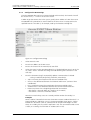
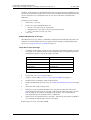
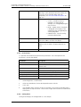
Contents
1 Introduction............................................................................................................. 1
1.1 Abbreviations and Glossary ................................................................................ 2
2 Description............................................................................................................... 3
2.1 IPBS ................................................................................................................... 3
2.1.1 IPBS with Internal Antenna ........................................................................ 3
2.1.2 IPBS with External Antennas ...................................................................... 5
2.2 IPBL ................................................................................................................... 6
2.2.1 Overview ................................................................................................... 6
2.2.2 Power Supply ............................................................................................. 6
2.2.3 LED indication ............................................................................................ 6
2.3 DECT Base Station (BS3x0) ................................................................................. 8
2.3.1 DECT Base Station ..................................................................................... 8
2.4 AC-adapter ........................................................................................................ 9
3 Safety Instructions ................................................................................................ 10
3.1 Safety Symbols ................................................................................................. 10
3.2 Protection Against Electrostatic Discharge (ESD) ............................................... 11
3.2.1 ESD Handling ........................................................................................... 11
3.3 Safety Aspects ................................................................................................. 11
3.3.1 IP-DECT Base Station ................................................................................ 11
3.3.2 BS3x0 Base Station .................................................................................. 11
3.3.3 IP-DECT Gateway ..................................................................................... 11
3.4 Regulatory Compliance Statements (EU/EFTA only) ........................................... 12
3.5 Regulatory Compliance Statements (USA and Canada only) ............................. 12
4 IP Security .............................................................................................................. 14
4.1 IP Security Terminology .................................................................................... 14
4.1.1 SSL/TLS .................................................................................................... 14
4.1.2 Public Key Infrastructure .......................................................................... 14
4.1.3 Cryptography ........................................................................................... 15
4.2 Introduction to IP Security in IP-DECT ............................................................... 16
4.2.1 Secure Web Access (https) ....................................................................... 16
4.2.2 TLS Certificates ........................................................................................ 16
4.3 IP-DECT Administrative functions ..................................................................... 17
4.3.1 Configuration - HTTP ............................................................................... 17
4.3.2 Configuration - Certificates ...................................................................... 17
5 Installation of the Base Station............................................................................ 18
5.1 Base Station Cabling ........................................................................................ 18
5.2 Install the Base Station ..................................................................................... 18
2009-04-15/ Ver. B
Installation and Operation Manual
IP-DECT Base Station & IP-DECT Gateway (software version 3.0.x)
TD 92579GB
5.2.1 Fix the Mounting Bracket to a Wall .......................................................... 18
5.2.2 Fix the Mounting Bracket to a Ceiling ...................................................... 19
5.2.3 Fix the Mounting Bracket to a Pole or Beam ............................................. 19
5.2.4 Use the Cable Ducts ................................................................................. 20
5.2.5 Secure the Cable ...................................................................................... 21
5.2.6 Pinning .................................................................................................... 21
5.2.7 Connect the Base Station Cables .............................................................. 23
5.2.8 Mount the Base Station ........................................................................... 23
5.3 Power the Base Station .................................................................................... 24
5.3.1 Power the IPBS over Ethernet ................................................................... 24
5.3.2 Power the BS3x0 over Express Powering Pair (EPP) and data pairs ............. 24
5.3.3 Power the Base Station with a Local Power Supply ................................... 24
6 Installation of the IPBL.......................................................................................... 25
6.1 Install the IPBL .................................................................................................. 25
6.2 Pin the IPBL Cable ............................................................................................ 26
6.2.1 Synchronization Cable ............................................................................. 26
6.2.2 RFP Cable ................................................................................................ 27
6.2.3 LAN Cable ............................................................................................... 27
6.3 Power the IPBL ................................................................................................. 29
6.3.1 110/230 VAC ........................................................................................... 29
6.3.2 48 VDC ................................................................................................... 30
7 Configuration ........................................................................................................ 31
7.1 Requirements ................................................................................................... 31
7.1.1 Web Browser Requirements ..................................................................... 31
7.2 Access the GUI ................................................................................................. 31
7.2.1 Determine the IP Address ......................................................................... 31
7.2.2 Change the Default Password .................................................................. 33
7.3 GUI Web Access .............................................................................................. 34
7.3.1 Login Page ............................................................................................... 34
7.3.2 Access Levels ........................................................................................... 34
7.3.3 Auditors .................................................................................................. 34
7.3.4 User Administrators ................................................................................. 34
7.3.5 System Administrators ............................................................................. 35
7.4 Configure the Mobility Master ......................................................................... 38
7.5 Configure the Standby Mobility Master ............................................................ 39
7.6 Configure the Pari Master ................................................................................ 39
7.7 Configure the Standby Pari Master ................................................................... 40
7.8 Configure the Master ....................................................................................... 41
7.9 Configure the Standby Master ......................................................................... 41
7.10 Plug and Play Configuration ........................................................................... 42
2009-04-15/ Ver. B
Installation and Operation Manual
IP-DECT Base Station & IP-DECT Gateway (software version 3.0.x)
TD 92579GB
7.11 Configure the Radio ....................................................................................... 42
7.12 Add Users ...................................................................................................... 43
7.12.1 Anonymous Registration ........................................................................ 43
7.12.2 Individual Registration ............................................................................ 44
7.13 Logout/Login Users ........................................................................................ 44
7.13.1 Logout Users ......................................................................................... 44
7.13.2 Login Users ............................................................................................ 45
8 Operation............................................................................................................... 46
8.1 General ............................................................................................................ 46
8.1.1 Change User Name and Password ............................................................ 46
8.1.2 Name the IPBS/IPBL .................................................................................. 46
8.1.3 Configure Automatic Firmware Update .................................................... 47
8.1.4 Configure the NTP Settings ...................................................................... 48
8.1.5 Configure Logging ................................................................................... 49
8.1.6 Configure the HTTP settings ..................................................................... 50
8.1.7 Configure the HTTP Client settings ........................................................... 51
8.1.8 SNMP ...................................................................................................... 51
8.1.9 Certificates .............................................................................................. 52
8.2 LAN ................................................................................................................. 57
8.2.1 Set DHCP Mode ....................................................................................... 57
8.2.2 Set a Static IP Address .............................................................................. 57
8.2.3 Dynamic IP address via DHCP ................................................................... 58
8.2.4 Link ......................................................................................................... 58
8.2.5 Configure VLAN ....................................................................................... 58
8.2.6 View LAN Statistics .................................................................................. 58
8.3 IP ..................................................................................................................... 59
8.3.1 Configure IP Settings ............................................................................... 59
8.3.2 Routing ................................................................................................... 59
8.4 LDAP ............................................................................................................... 59
8.4.1 Configure LDAP Server ............................................................................. 60
8.4.2 Check LDAP Server Status ........................................................................ 60
8.4.3 Configure LDAP Replicator ....................................................................... 61
8.4.4 Check LDAP Replicator Status .................................................................. 65
8.4.5 Expert tool ............................................................................................... 65
8.5 DECT ............................................................................................................... 66
8.5.1 Change System Name and Password ........................................................ 66
8.5.2 Change Subscription Method ................................................................... 67
8.5.3 Configure Authentication Code ............................................................... 67
8.5.4 Select Tones ............................................................................................. 67
8.5.5 Set Default Language ............................................................................... 67
2009-04-15/ Ver. B
Installation and Operation Manual
IP-DECT Base Station & IP-DECT Gateway (software version 3.0.x)
TD 92579GB
8.5.6 Set Frequency Band ................................................................................. 68
8.5.7 Enable Carriers ......................................................................................... 68
8.5.8 Local R-Key Handling ............................................................................... 68
8.5.9 No Transfer on Hangup ............................................................................ 68
8.5.10 Configure Coder .................................................................................... 69
8.5.11 Configure Supplementary Services ......................................................... 69
8.5.12 Select Mode ........................................................................................... 70
8.5.13 Set Master Id ......................................................................................... 71
8.5.14 Enable Pari Function ............................................................................... 71
8.5.15 Configure Gatekeeper ........................................................................... 71
8.5.16 Registration for Anonymous Devices ...................................................... 72
8.5.17 Select Mobility Master Mode .................................................................. 73
8.5.18 Connect Mobilty Master to other Mobility Master(s) ............................... 73
8.5.19 Connect Master to a Mobility Master ..................................................... 73
8.5.20 Enable the Radio .................................................................................... 74
8.5.21 Enter IP Address to the Pari Master and the Standby Pari Master ............ 74
8.5.22 Multiple Radio Configuration ................................................................. 74
8.5.23 PARI ....................................................................................................... 74
8.5.24 SARI ...................................................................................................... 75
8.5.25 Configure Air Synchronization ............................................................... 75
8.6 VoIP ................................................................................................................. 80
8.6.1 Add instance id to the user registration with the IP-PBX ........................... 80
8.6.2 Session Timer (initial value) ...................................................................... 80
8.7 UNITE .............................................................................................................. 80
8.7.1 Configure Messaging ............................................................................... 80
8.7.2 Device Management ................................................................................ 81
8.7.3 Service Discovery ...................................................................................... 81
8.7.4 Send Status Log ....................................................................................... 81
8.8 Users ............................................................................................................... 81
8.8.1 Add a User .............................................................................................. 82
8.8.2 Search for User Information ..................................................................... 82
8.8.3 Show all Registered Users in the IP-DECT System ...................................... 82
8.8.4 Show Anonymous ................................................................................... 82
8.9 Device Overview .............................................................................................. 83
8.9.1 Radios ..................................................................................................... 83
8.9.2 Air Sync ................................................................................................... 84
8.9.3 RFPs ......................................................................................................... 84
8.9.4 Sync Ring ................................................................................................. 87
8.9.5 Sync Ports ................................................................................................ 87
8.10 Traffic ............................................................................................................ 88
8.10.1 Display All Ongoing Calls in the System .................................................. 88
2009-04-15/ Ver. B
Installation and Operation Manual
IP-DECT Base Station & IP-DECT Gateway (software version 3.0.x)
TD 92579GB
8.10.2 Display Calls ........................................................................................... 88
8.10.3 Handover ............................................................................................... 88
8.11 Gateway ........................................................................................................ 89
8.11.1 General ................................................................................................. 89
8.11.2 Interfaces ............................................................................................... 90
8.11.3 SIP Interfaces ......................................................................................... 91
8.11.4 Gatekeeper Interfaces ............................................................................ 96
8.11.5 Routes – Configuration .......................................................................... 98
8.11.6 Show Active Calls ................................................................................ 101
8.12 Backup ........................................................................................................ 103
8.13 Upgrade from IPBS/IPBL software version 2.x.x to 3.x.x ................................. 104
8.13.1 IPBS Upgrade ....................................................................................... 104
8.13.2 IPBL Upgrade ....................................................................................... 104
8.13.3 Configuration ...................................................................................... 104
8.13.4 Downgrade from software version 3.x.x to 2.x.x .................................. 105
8.14 Update ........................................................................................................ 106
8.14.1 Update Configuration .......................................................................... 106
8.14.2 Update Firmware ................................................................................. 106
8.14.3 Update the Boot File ............................................................................ 107
8.14.4 Update the RFPs ................................................................................... 107
8.15 Diagnostics .................................................................................................. 108
8.15.1 Logging ............................................................................................... 108
8.15.2 Tracing ................................................................................................. 108
8.15.3 Alarms ................................................................................................. 108
8.15.4 Events .................................................................................................. 109
8.15.5 Performance ........................................................................................ 110
8.15.6 Config Show ....................................................................................... 110
8.15.7 Ping ..................................................................................................... 111
8.15.8 Traceroute ........................................................................................... 111
8.15.9 Environment ........................................................................................ 112
8.15.10 RFP Scan ............................................................................................ 112
8.15.11 Service Report .................................................................................... 112
8.16 Reset ........................................................................................................... 113
8.16.1 Idle Reset ............................................................................................. 113
8.16.2 Immediate Reset .................................................................................. 113
8.16.3 TFTP Mode ........................................................................................... 113
8.16.4 Boot .................................................................................................... 113
8.17 Reset Using the Reset Button ....................................................................... 113
9 Commissioning .................................................................................................... 114
9.1 Radio coverage verification tests .................................................................... 114
2009-04-15/ Ver. B
Installation and Operation Manual
IP-DECT Base Station & IP-DECT Gateway (software version 3.0.x)
TD 92579GB
9.1.1 Base Station Operation Test .................................................................... 114
9.1.2 Coverage Area Test ................................................................................ 114
9.1.3 Evaluation .............................................................................................. 114
9.2 Cordless Extension Number Test ..................................................................... 114
10 Troubleshooting ................................................................................................ 116
10.1 Load Firmware Using the Gwload Tool ......................................................... 116
10.2 Fault Code Descriptions ............................................................................... 116
11 Related Documents ........................................................................................... 119
Appendix A: How to Use the Update Server ....................................................... 121
Appendix B: RFP Power Consumption.................................................................. 126
Appendix C: Local R-Key Handling ....................................................................... 128
Appendix D: Database Maintenance .................................................................... 129
Appendix E: Load Balancing.................................................................................. 131
2009-04-15/ Ver. B
Installation and Operation Manual
IP-DECT Base Station & IP-DECT Gateway (software version 3.0.x)
1
TD 92579GB
Introduction
This documet describes how to install and operate the following equipment:
• IPBS Base Station (IPBS) 1
• IPBL 2
The document is intended as a guide for installation, troubleshooting and maintenance
purposes and are relevant for the following personnel:
• System administrator
• Service technician
For information on the IP-DECT system, see System Description, Ascom IP-DECT System,
TD 92375GB.
For information about supported PBXs contact your supplier.
1.In previous documentation, IPBS Base Station (or IPBS) was sometimes referred to as IP-DECT Base Station.
2.IIn previous documentation, IPBL was sometimes referred to as IP-DECT Gateway.
2009-04-15/ Ver. B
1
Installation and Operation Manual
IP-DECT Base Station & IP-DECT Gateway (software version 3.0.x)
1.1
TD 92579GB
Abbreviations and Glossary
Base Station Common name for IPBS and DECT Base Station (BS3x0)
DECT
Digital Enhanced Cordless Telecommunications:
global standard for cordless telecommunication.
DECT Base
Station
Another name for BS3x0
DHCP
Dynamic Host Configuration Protocol
DTMF
Dual Tone Multiple-Frequency
FER
Frame Error Rate
GUI
Graphical User Interface
IP
Internet Protocol:
global standard that defines how to send data from one computer to
another through the Internet
IPBL
Previously called IP-DECT Gateway or, more commonly, as "the Blade"
IPBS
Also referred to as IPBS Base Station. Previously called IP-DECT Base Station
LAN
Local Area Network:
a group of computers and associated devices that share a common
communication line.
LDAP
Lightweight Directory Access Protocol
PBX
Private Branch Exchange:
telephone system within an enterprise that switches calls between local lines
and allows all users to share a certain number of external lines.
PSCN
Primary receiver Scan Carrier Number:
defines the RF carrier on which one receiver will be listening on the next
frame.
RFP
Radio Fixed Part. DECT base Station part of the DECT Infrastructure.
RFPI
Radio Fixed Part Identity
RSSI
Radio Signal Strength Information
RTP
Real-Time Transport Protocol
SST
Site Survey Tool
ToS
Type of Service
VLAN
Viritual Local Area Network
2009-04-15/ Ver. B
2
Installation and Operation Manual
IP-DECT Base Station & IP-DECT Gateway (software version 3.0.x)
2
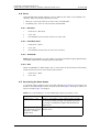
TD 92579GB
Description
This section gives a general description of the following devices:
• IPBS, see 2.1 IPBS
• IPBL, see 2.2 IPBL on page 6
• DECT Base Station, see 2.3 DECT Base Station (BS3x0) on page 8.
2.1
IPBS
The following versions of the IPBS are available:
• IPBS with Internal antenna
• IPBS with External antennas
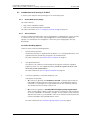
2.1.1
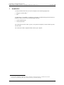
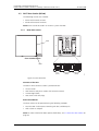
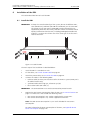
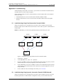
IPBS with Internal Antenna
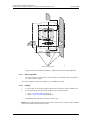
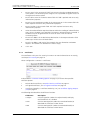
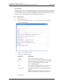
Figure 1.
LED2
Reset
Front viewBack view
Test
(RJ12)
LAN
(RJ45)
Power Supply
(RJ45)
005
LED1
Figure 1. IPBS Overview
Contents of the Box
The box in which the IPBS is packed contains:
• An IPBS with integrated antennas
• A mounting bracket
• Two screws with wall plugs
Power Distribution
The IPBS can be powered using the following methods:
• Power over Ethernet, IEEE 802.3af
• A local AC-adapter
2009-04-15/ Ver. B
3
Installation and Operation Manual
IP-DECT Base Station & IP-DECT Gateway (software version 3.0.x)
TD 92579GB
Note: For more information about power distribution, see 5.3 Power the Base Station on
page 24.
Software
The software in the IPBS can be updated by downloading new software without
disconnecting the equipment. The new software is stored in flash memory. See 8.14
Update on page 106 for information.
Connectors
• Two 8-pin RJ45 modular jacks for LAN/PoE and powering
• A 6-pin RJ12 modular jack for factory testing
LEDs
Status of LED1 (lower LED)
Description
Steady Green
Operational
Quick flashing amber
Download of firmware in progress.
Steady Amber
TFTP mode
Alternating red/green
No Ethernet connection
Status of LED2 (upper LED)
Description
Not lit
IPBS operational and no traffic
Air synchronization OK
Steady green
IPBS operational and traffic
Air synchronization OK
Slow flashing green
Air synchronization OK and fully occupied with
traffic
Flashing amber
Air synchronization adequate and no traffic
Slow flashing amber
Air synchronization adequate and fully occupied
with traffic
Steady amber
Air synchronization adequate and traffic
Flashing red
No air synchronization - searching for air sync
candidates
Quick flashing red
Download of RFP software in progress
Note: All amber statuses are warnings that Air synchronization, although still adequate, is
fading and might be lost. A flashing red indicates lost Air synchronization.
2009-04-15/ Ver. B
4
Installation and Operation Manual
IP-DECT Base Station & IP-DECT Gateway (software version 3.0.x)
2.1.2
TD 92579GB
IPBS with External Antennas
The IPBS is available with two omni-directional external antennas. Other external antennas
can be mounted as well. This section contains the differences between the IPBS with
internal and external antennas. For all other information see 2.1.1 IPBS with Internal
Antenna on page 3.
Contents of the Box
The box in which the IPBS is packed contains:
•
•
•
•
An IPBS for external antennas
Two antennas
A mounting bracket
Two screws with wall plugs
Note: The IPBS cannot be mounted with the antennas pointing downwards as the
mounting bracket does not support it.
Insert the antennas into the IPBS before following the installation instructions in 5.2 Install
the Base Station on page 18.
2009-04-15/ Ver. B
5
Installation and Operation Manual
IP-DECT Base Station & IP-DECT Gateway (software version 3.0.x)
2.2
TD 92579GB
IPBL
The following versions of the IPBL are available:
• IPBL IP-DECT Gateway VAC/VDC (for 110/230 VAC or 48 VDC)
• IPBL IP-DECT Gateway VDC (for 48 VDC)
2.2.1
Overview
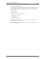
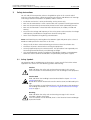
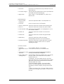
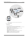
Figure 2.
base station
1
1 2
synchronization
2
ring in
3
ring out
4
01
02
03
04
05
06
07
08
09
10
11
12
13
14
15
16
reference
in
out
5
6
006
lan
Figure 2. Overview of the IPBL
Pos.
Name
Function
1
Reset
Resets the IPBL, see 8.17 Reset Using the Reset Button on
page 113 for more information.
2
Status LED
Indicates the status on the IPBL.
3
Lan
10BASE-T/100BASE-T Ethernet interface.
LAN1 port must be used in the IP-DECT system (LAN2 port
is for administration only).
4
Synchronization
Sync ring in and sync ring out interfaces.
5
Reference
Reference sync in and reference sync out interfaces.
6
Base station 01-16
ISDN UPN DECT base station interfaces.
2.2.2
Power Supply
The power supply are located at the rear of the IPBL. The IPBL can be powered using the
following alternatives:
• 110/230 VAC (only IPBL IP-DECT Gateway VAC/VDC)
• 48 VDC
Note: For more information, see 6.3 Power the IPBL on page 29.
Software
The software in the IPBL can be updated by downloading new software without
disconnecting the equipment. The new software is stored in flash memory. See 8.14
Update on page 106 for information.
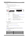
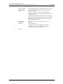
2.2.3
LED indication
Figure 3.
Status LED
Description
Not lit
Not powered, status is not defined.
Flashing slow green
When pressing the reset button.
Flashing fast green
Firmware update or clear config after long reset.
2009-04-15/ Ver. B
6
Installation and Operation Manual
IP-DECT Base Station & IP-DECT Gateway (software version 3.0.x)
Steady green
Status OK, system is fully operational.
Steady red
Status Fail, system error condition.
Steady amber
System is in TFTP server mode.
TD 92579GB
Figure 4.
Figure 5.
Base station LED
Description
Not lit
No UPN link established.
Flashing
UPN link established (activated state), RFP is not
operational.
Steady
RFP is fully initialised and operational.
Figure 6.
Base station LED
Description
Not lit
No speech activity in RFP.
Flashing
All speech channels occupied in RFP.
Steady
Speech activity in RFP.
Figure 7.
Sync/Ref sync LED
Description
Not lit
No sync communication established.
Steady
Communication established.
Figure 8.
Sync/Ref sync LED
Description
Not lit
Sync port not selected as input sync source.
Flashing
Sync port selected as input sync source but the
sync signal is not in sync.
Steady
Sync port selected as input sync source and the
sync signal is in sync.
Figure 9.
Lan LED
Description
Not lit
No link.
Flashing
Link present and network activity.
Steady
Link present, but no network activity.
Figure 10.
Lan LED
Description
Not lit
10 Mbps operation.
Steady
100 Mbps operation.
2009-04-15/ Ver. B
7
Installation and Operation Manual
IP-DECT Base Station & IP-DECT Gateway (software version 3.0.x)
2.3
TD 92579GB
DECT Base Station (BS3x0)
The following versions are available:
• BS330 with Internal antenna
• BS340 with External antennas
Note: BS370 cannot be used in an IP-DECT system with IPBS.
2.3.1
DECT Base Station
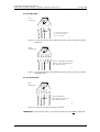
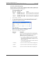
Figure 11.
LED2
Front viewBack view
Test
(RJ12)
Data/Power
(RJ45)
Data/Power
(RJ45)
007
LED1
Figure 3. BS3x0 Overview
Contents of the Box
The box in which the base station is packed contains:
•
•
•
•
A base station
Two antennas (only base station with external antenna)
A mounting bracket
Two screws with wall plugs
Power Distribution
The base station can be powered using the following methods:
• From the IPBL via the Express Powering Pair (EPP) and data pairs
• With a local AC-adapter
Note: For more information about power distribution, see 5.3 Power the Base Station on
page 24.
2009-04-15/ Ver. B
8
Installation and Operation Manual
IP-DECT Base Station & IP-DECT Gateway (software version 3.0.x)
TD 92579GB
Software
The software in the BS3x0 can be updated by downloading new software without
disconnecting the equipment. The new software is stored in flash memory. See 8.14
Update on page 106 for information.
Connectors
• Two 8-pin RJ45 modular jacks for data and powering
• A 6-pin RJ12 modular jack for factory testing
LEDs
2.4
Status of LED1 (lower LED)
Description
Steady Green
Power LED
Status of LED2 (upper LED)
Description
Not lit
Base station operational and no traffic on the
base station.
Flashing green
All 8 speech channels are in use.
Steady green
Base station operational and traffic on the base
station.
Flashing amber
Software is being downloaded to the base station
Steady amber
Base station is OK, but not available (self-test, not
initialized,no communication with IPBL)
AC-adapter
The AC-adapter is used to power a base station locally.
Note: The maximum length of cable from adapter must not exceed 10 meters.
Versions (different type of mains plug)
BSX-0013
For European countries except U.K.
BSX-0014
For U.K.
BSX-0015
For US/Canada
BSX-0016
For Australia
IMPORTANT: If local power supply is used for the RFPs, the EPP cable pair must not be
connected.
2009-04-15/ Ver. B
9
Installation and Operation Manual
IP-DECT Base Station & IP-DECT Gateway (software version 3.0.x)
3
TD 92579GB
Safety Instructions
For safe and efficient operation, observe the guidelines given in this manual and all
necessary sefety precautions. Follow the operating instructions and adhere to all warnings
and safety precautions located on the product and this manual.
•
•
•
•
Installation and service is to be performed by service persons only.
IPBL must be connected to a mains socket outlet with a protective earthing connection.
IPBL must be permanently connected to protective earth when powered by 48 VDC.
IPBL must be mounted in a Restricted Area Location (RAL) in Sweden, Finland and
Norway.
• Ensure that the voltage and frequency of the mains power socket matches the voltage
and frequency inscribed on the equipment’s electrical rating label.
• Never install telephone wiring during a thunderstorm.
Note: Avoid touching or punching down the IPBS/RFP signal and power pairs as there is
48Vdc or 24Vdc present on these wires at all times.
• Always install the base station conforming to relevant national installation rules.
• Disconnect all power sources before servicing the equipment.
• Use only approved spare parts and accessories. The operation of non-approved parts
cannot be guaranteed and may cause damage or danger.
• Only approved power supplies according to valid editions of EN/IEC/CSA/UL/AU/NZS
60950 are to be used when the IPBS/RFPs are powered by local power supplies.
3.1
Safety Symbols
For protection and to avoid damage to the IP-DECT system you will find stickers where
applicable. The stickers have the following symbols and meaning:
Figure 12.
Caution
Read and follow the safety rules and warning messages in this manual.
If the instructions are not followed, there is risk of damage to the equipment.
Caution ESD
Read and follow the handling instructions described in chapter 3.2.1 ESD
Handling on page 11.
Boards which contain Electrostatic Sensitive Devices (ESD) are indicated by this
sign.
If the instructions are not followed, there is risk of damage to the equipment.
For handling these boards see 3.2 Protection Against Electrostatic Discharge
(ESD) on page 11.
Warning
Read and follow the safety rules and warning messages in this manual.
Hazardous voltages are present.
If the instructions are not followed, there is risk of electrical shock and danger
to personal health.
2009-04-15/ Ver. B
10
Installation and Operation Manual
IP-DECT Base Station & IP-DECT Gateway (software version 3.0.x)
3.2
TD 92579GB
Protection Against Electrostatic Discharge (ESD)
Integrated circuits are sensitive to ESD.To avoid damage caused by ESD, service engineers
and other people must handle equipment and boards carefully.
Electronic equipment has become more resistive to ESD, but we see an increase of
situations where static electricity can build up. This is caused by an increasing application
of man–made fibres like nylon, acrylic, etc. which are capable of generating ESD of 10,000
Volts and more.
Walking across a nylon carpet, even for a few feet, could cause a person to be charged–up
to more than 10,000 Volts.
Under these conditions, if a system board or a (C)MOS device is touched it could easily be
damaged. Although the device may not be totally defective, it is often degraded, causing
it to fail at a later date without apparent reason.
To make sure that equipment and parts are well protected during shipment, special
packaging materials are utilized. System boards will be shipped in anti–static bags and
(C)MOS devices and other sensitive parts in small shielded boxes.
3.2.1
ESD Handling
In the interest of quality and reliability, it is advisable to observe the following rules when
handling system parts:
• Keep parts in their protective packaging until they are needed.
• When returning system parts like EEPROMS to the factory, use the protective
packaging as described.
• Never underestimate the damaging power ESD can have and be especially careful
when temperatures are below freezing point and during very warm weather in
combination with low humidity. Make sure that the environmental conditions remain
within the limits specified in the components’ data sheets.
IMPORTANT: In the interest of quality and reliability system boards and other parts
returned for exchange or credit may be refused if the proper protective
packaging is omitted!
3.3
Safety Aspects
3.3.1
IP-DECT Base Station
The IP-DECT Base Station meets the valid editions of safety standard EN/IEC/CSA/UL/AU/
NZS 60950-1. The system is a class III equipment for stationary wall mounting.
3.3.2
BS3x0 Base Station
The IP-DECT Base Station meets the valid editions of safety standard EN/IEC/CSA/UL/AU/
NZS 60950-1. The system is a class III equipment for stationary wall mounting.
3.3.3
IP-DECT Gateway
The IP-DECT Gateway meets the valid editions of safety standard EN/IEC/CSA/UL/AU/NZS
60950-1.
2009-04-15/ Ver. B
11
Installation and Operation Manual
IP-DECT Base Station & IP-DECT Gateway (software version 3.0.x)
3.4
TD 92579GB
Regulatory Compliance Statements (EU/EFTA only)
The equipment are intended to be used in the whole EU&EFTA.
The equipment are in compliance with the essential requirements and other relevant
provisions of R&TTE Directive 1999/55/EC. The Declarations of Conformity may be
consulted at:
http://www.ascom.com/ws/products_ws.htm
The IP-DECT Base Station, BS3x0 Base Station and IP-DECT Gateway are marked with the
label
.
3.5
Regulatory Compliance Statements (USA and Canada only)
FCC complience statements
The equipment have been tested and found to comply with the limits for a Class B digital
device, pursuant to part 15 of the FCC rules. These limits are designed to provide
reasonable protection against harmful interference in a residential installation. The
equipment generates, uses and can radiate radio frequency energy and, if not installed
and used in accordance with the instructions, may cause harmful interference to radio
communications.
However, there is no guarantee that interference will not occur in a particular installtion. If
this equipment does cause harmful interference to radio or television reception, which can
be determined by turning the equipment off and on, the user is encouraged to try to
correct the interference by one or more of the following measures:
• Reorient or relocate the receiving antenna
• Increase the separation between the equipment and the receiver.
• Connect the equipment into an outlet on a circuit different from that to which the
receiver is connected.
• Consult the dealer or an experienced radio/tv technician for help.
Information to user
This device complies with Part 15 of the FCC Rules. Operation is subject to the following
two conditions:
(1) this device may not cause harmful interference, and
(2) this device must accept any interference recieved, including interference that may
cause undesired operation.
IC Requirements for Canada
This Class B digital apparatus complies with Canadian ICES-003.
Cet appareil numérique de la Classe B conforme á la norme NMB-003 du Canada.
Modifications
Any modifications not expressly approved by Ascom could void the user's authority to
operate the equipment.
2009-04-15/ Ver. B
12
Installation and Operation Manual
IP-DECT Base Station & IP-DECT Gateway (software version 3.0.x)
TD 92579GB
Exposure to radio frequency signals
This device complies with FCC RF radiation exposure limits set forth for an uncontrolled
environment. The antenna used for this transmitter must be installed to provide a
separation distance of at least 20 cm from all persons and must not be co-located or
operating in conjunction with any other antenna or transmitter.
2009-04-15/ Ver. B
13
Installation and Operation Manual
IP-DECT Base Station & IP-DECT Gateway (software version 3.0.x)
4
TD 92579GB
IP Security
4.1
IP Security Terminology
4.1.1
SSL/TLS
Note: Secure Socket Layer (SSL) has been renamed Transport Layer Security (TLS). TLS 1.0
is based on SSL 3.0/3.1. This document hereafter uses the term TLS.
TLS is a security mechanism based on cryptography (see 4.1.3 Cryptography) and is used
for encrypting communications between users and TLS-based Websites. The encryption
prevents eavesdropping and tampering with any transmitted data.
TLS operates on the OSI Model Level 5 and uses PKI (see 4.1.2 Public Key Infrastructure).
4.1.2
Public Key Infrastructure
Public Key Infrastructure (PKI) is a component of Public Key Chryptography (PKC) that
uses:
• Public Key Certificates, see Public Key Certificates (Digital Certificates)
• Certificate Authorities, see Certificate Authorities
Public Key Certificates (Digital Certificates)
Public Key Certificates are used for key exchange and authentication. They are simply
electronic documents (files) that incorporate a digital signature to bind together a public
key with an identity (information such as the name or a person or organization, their
address, and so forth).
The signature may be signed by a trusted entity called a Certificate Authority (CA), see
Certificate Authorities.
The most common use of public key certificates is for TLS certificates (https websites).
Certificate Authorities
A Certificate Authority or Certification Authority (CA) is a trusted entity which issues
public key certificates. The certificates contain a public key and the identity of the owner.
The CA asserts that the public key belongs to the owner, so that users and relying parties
can trust the information in the certificate.
Certificate Signing Request (CSR) or Certification Request is a message that is
generated and sent to a CA in order to apply for a TLS certificate. Before the CSR is
created a key pair is generated, the private key kept secret. The CSR will contain the
corresponding public key and information identifying the applicant (such as distinguished
name). The private key is not part of the CSR but is used to digitally sign the entire
request. Other credentials may accompany the CSR.
If the request is successful, the CA will send back an identity certificate that has been
digitally signed with the CA’s private key.
A CSR is valid for the server where the certificate will be installed.
2009-04-15/ Ver. B
14
Installation and Operation Manual
IP-DECT Base Station & IP-DECT Gateway (software version 3.0.x)
4.1.3
TD 92579GB
Cryptography
Cryptography is the encoding of messages to render them unreadable by anyone other
than their intended recipient(s). Modern cryptography uses complex algorithms
implemented on modern computer systems.
Cryptography tasks can be divided into the two general categories Encryption and
Authenitication.
Encryption
Encryption is the scrambling of information so that the original message cannot be
determined by unauthorized recipients by applying an encryption algoritm to the message
plaintext producing ciphertext (appearently random bits). A decryption algoritm, if given
the correct key, converts the ciphertext back into plaintext. Public key algoritms use paired
keys, one for encryption and another for decryption.
Authentication
Authentication is the verification of a message’s sender. This requires the message to be
protected so it cannot be altered, usually by generating a digital signature formed by a
hash of the message. Only the correct key can generate a valid signature.
2009-04-15/ Ver. B
15
Installation and Operation Manual
IP-DECT Base Station & IP-DECT Gateway (software version 3.0.x)
4.2
TD 92579GB
Introduction to IP Security in IP-DECT
A secure system requires more planning than an unsecured system.
4.2.1
Secure Web Access (https)
For IP-DECT devices
• https access should be enabled
• http access should preferably be disabled
For more information see 8.1.6 Configure the HTTP settings on page 50 .
4.2.2
TLS Certificates
Security in Web-based applications rely on cryptography. Cryptographical systems are only
as secure as their keys. This makes Key Management a critical and often neglected
concern. TLS Certificates have emerged as a clever way of managing large scale key
distribution.
Certificate Handling Options
There are three certificate handling options:
1
Default Device certificate
The default certificate is supplied with the device. It is a self-signed certificate. Selfsigned certificates provide only encryption, not authentication.
For more information see Default Device Certificate on page 53.
2
Self-signed certificates
This option is for customers not planning on having their certificates signed by
public or private CAs. Self-signed certificates provide encryption but do in most
cases not provide authentication.
For more information see Self-signed Certificates on page 54.
3
Certificates signed by a Certificate Authority (CA).
Two options are possible:
• A) Certificates signed by the customer’s own CA. Customers possessing the
knowledge and intrastructure to house their own CA could build an internal
enterprise CA, enabling them to sign (approve) their own certificate requests.
This would make the customer a private CA.
• B) Certificates signed by a trusted public third party entity/organization.
There are only about a dozen issuers who have the authority to sign certificates
for servers worldwide. An example is VeriSign. To use a public CA for certificate
approvals the IP-DECT system would in most cases need to be connected to the
Internet and hold a fully qualified domain name.
For more information see Certificate Signing Request (CSR) on page 55.
2009-04-15/ Ver. B
16
Installation and Operation Manual
IP-DECT Base Station & IP-DECT Gateway (software version 3.0.x)
4.3
TD 92579GB
IP-DECT Administrative functions
4.3.1
Configuration - HTTP
The HTTP Tab is used to configure the type of web access that should be allowed for the
device, includes a field for configuring https access.
For more information see 8.1.6 Configure the HTTP settings on page 50.
4.3.2
Configuration - Certificates
The Certificates tab lists the certificate used by web browsers to authenticate the identity
of the device (Web server).
For more information see 8.1.9 Certificates on page 52.
2009-04-15/ Ver. B
17
Installation and Operation Manual
IP-DECT Base Station & IP-DECT Gateway (software version 3.0.x)
5
TD 92579GB
Installation of the Base Station
This section describes how to install the IPBS and BS3x0. Both base stations can be fixed to
a wall, a ceiling, a pole or a beam, by means of the mounting bracket included. When
fixing the base station to a wall or ceiling the included plugs and screws must be used.
When fixing it to a pole or beam a strap or a flexible metal band must be used, this is not
included.
Note: Fixing the base station to metal surfaces requires special consideration and is not
recommended for several reasons. If this is unavoidable try to ensure a distance between
the base station and the metal surface of, preferably, 1 meter. If this is not possible to
achive the best option to use is base station with internal antennas/BS330.
5.1
Base Station Cabling
Recommended base station cable is a standard CAT5 unshielded ethernet cable with
minimum 26 AWG copper conductors, this cable is also used for powering the base
station. It is assumed that installation personnel know how to crimp RJ45 connectors to a
cable.
Note: Since the distance between the base station and the wall is limited, a RJ45 modular
jack without cable retention must be used.
Note: Ensure that during the installation of an base station, each base station is given an
extra length (5-10 metres) of cable because it is possible that it will have to be moved for
one reason or another.
5.2
Install the Base Station
The base station can be mounted vertically or horizontally. Mount the base station at
places and positions as determined in the base station plan, see System Planning, Ascom
IP-DECT, TD 92422GB. The base station must be placed in a way that it is not facing large
metal objects such as large heating pipes.
5.2.1
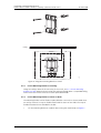
Fix the Mounting Bracket to a Wall
Fix the mounting bracket (see figure 4 on page 19) to the wall as follows:
1
Hold the mounting bracket with its flat side against the wall with the text ‘TOP’
upwards and mark the two holes. The minimum distance between the upper hole
and the ceiling or any object above the base station must be at least 65 mm, see
Figure 4. If the distance is less than 65 mm, the base station cannot be slid onto the
bracket.
2
When using wall plugs: Drill the two holes using a ∅ 6 mm drill and insert the
included wall plugs.
3
Position the mounting bracket with its flat side to the wall and fasten it with the
two included ∅ 3.5 mm screws.
2009-04-15/ Ver. B
18
Installation and Operation Manual
IP-DECT Base Station & IP-DECT Gateway (software version 3.0.x)
TD 92579GB
Figure 13.
Ceiling
65 mm
011
TOP
Figure 4. Fixing the mounting bracket to a wall
5.2.2
Fix the Mounting Bracket to a Ceiling
Fixing to a ceiling is done in the same way as the a wall, see 5.2.1 Fix the Mounting
Bracket to a Wall. When the base station has to be positioned above a suspended ceiling,
make sure that the front of the base station points downwards.
5.2.3
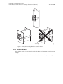
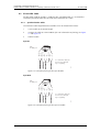
Fix the Mounting Bracket to a Pole or Beam
The mounting bracket can be fixed to a pole (diameter ≥ 45 mm) or a beam (wider than
50 mm) by means of a strap or flexible metal band less than 30 mm wide. The strap or
flexible metal band is not included in the box.
1
2009-04-15/ Ver. B
Fix the mounting bracket to a pole or beam using the metal band, see Figure 5.
19
Tied wrongly
TD 92579GB
012
Installation and Operation Manual
IP-DECT Base Station & IP-DECT Gateway (software version 3.0.x)
14. Figure
Figure 5. Fixing the mounting bracket to a pole or beam
5.2.4
Use the Cable Ducts
When the base station is mounted to the wall, cable ducts can be used to route the wiring
through.
1
2009-04-15/ Ver. B
Fix the cable duct to the wall in one of the positions shown in figure 6 on page 21.
20
Installation and Operation Manual
IP-DECT Base Station & IP-DECT Gateway (software version 3.0.x)
TD 92579GB
Figure 15.
65 mm
57 mm
TOP
125 mm
70 mm
15 mm thick cable ducts
013
75 mm
Figure 6. Minimum distances between a cable duct and the mounting bracket
5.2.5
Secure the Cable
1
For safety reasons secure the base station cable to a convenient point at about 30
cm from the base station.
If for some reason the base station drops, it is secured by the cable.
5.2.6
Pinning
1
Cut the cable to the correct length and connect the cable to a RJ45 modular jack.
2
For information on the pinning of the data jack see the following:
• IPBS, Pin the IPBS Cable on page 22.
• BS3x0, Pin the BS3x0 Cable on page 22.
Do not plug the connector in the base station yet!
Note: Since the distance between the base station and the wall is limited, a RJ45 modular
jack without cable retention must be used.
2009-04-15/ Ver. B
21
Installation and Operation Manual
IP-DECT Base Station & IP-DECT Gateway (software version 3.0.x)
TD 92579GB
Pin the IPBS Cable
Figure 16.
1
Rx
Pwr
Pwr
Rx
Pwr
Pwr
Tx
Tx
RJ45
modular jack
2
3
4
5
6
7
8
014
Tx = Transmitter data pair
Rx = Reciever data pair
Pwr = Power pairs
Figure 7. Connector pinning of the LAN/PoE connector, power feed over the spare
cable pairs.
Figure 17.
Tx/Pwr
Tx/Pwr
Rx/Pwr
Spare
Spare
Rx/Pwr
Spare
Spare
RJ45
modular jack
1
2
3
4
5
6
7
8
015
Tx/Pwr = Transmitter & power pair
Rx/Pwr = Reciever & power pair
NC = Not Connected
Figure 8. Connector pinning of the LAN/PoE connector, power feed over the Rx/Tx
data cable pairs.
Pin the BS3x0 Cable
Figure 18.
1
2
SC1-a
SC0-a
SC0-b
SC1-b
NC
NC
EPP-b
EPP-a
RJ45
modular jack
3
4
5
6
7
8
008
SC = Serial Channel
EPP = Express Power Pairs
NC = Not Connected
Figure 9. Connector pinning of the Data connector
IMPORTANT: If local power supply is used, the EPP cable pair must not be connected.
2009-04-15/ Ver. B
22
Installation and Operation Manual
IP-DECT Base Station & IP-DECT Gateway (software version 3.0.x)
5.2.7
TD 92579GB
Connect the Base Station Cables
1
If it is required that the cables enter the base station centrally from above, guide the
cables through the recess in the middle of the base station as shown in figure 10 on
page 23.
Figure 19.
016
Data cable
Power cable
(if used)
Figure 10. Cables entering centrally from above
2
Plug the modular jack of the data cable into one of the data/power connectors.
3
When an AC-adapter is used:
• Plug the modular jack of the AC-adapter in one of the data/power connectors.
• Plug the AC-adapter into a wall-outlet.
5.2.8
Mount the Base Station
1
Hold the base station flat against the mounting bracket and move it downwards
until it clicks, see Figure 11.
017
Figure 20.
Figure 11. Mounting the base station
2009-04-15/ Ver. B
23
Installation and Operation Manual
IP-DECT Base Station & IP-DECT Gateway (software version 3.0.x)
5.3
TD 92579GB
Power the Base Station
The base station is powered the following ways:
• Power over Ethernet (only IPBS).
• Power over Express Powering Pairs (EPP) and data pairs (only BS3x0)
• By a local power supply.
Note: Do not power the base station using both power supplies. Parallel powering will
not harm the base station but it can disturb the signalling.
5.3.1
Power the IPBS over Ethernet
The IPBS supports Power over Ethernet, IEEE 802.3af, class 2. The IPBS power
consumption is maximum 5W. But according to the PoE standard for class 2 the PoE
power source will allocate 7W to the IPBS. This must be regarded when planning the
powering of the IPBSs so that the power limit of the PoE power source is not exceeded.
The PoE standard supports two ways of feeding the power:
1
Power over the Rx/Tx data pairs.
2
Power over the spare cable pairs.
Both power feed methods are supported in the IPBS, it is also insensitive to change of the
polarity.
5.3.2
Power the BS3x0 over Express Powering Pair (EPP) and data pairs
When a base station is powered remotely via the IPBL, the maximum length between the
base station and the IPBL depends on the supply voltage, the number of twisted pairs used
and the wire size. The length of the cable should never exceed "data-limited" length of
the cable, see Appendix B: RFP Power Consumption on page 126.
5.3.3
Power the Base Station with a Local Power Supply
Powering the base station with a local power supply can be done using the second data/
power inlet on the base station. The base station can be powered individually by an ACadapter. The AC-adapter is provided with an 8-pin RJ45 plug that can be plugged into the
Power Supply jack. For specification see 2.4 AC-adapter on page 9.
Note: Only approved power supply according to valid editions of EN/IEC/CSA/UL/AU/NZS
60950 is to be used when the base station is powered by a local power supply.
2009-04-15/ Ver. B
24
Installation and Operation Manual
IP-DECT Base Station & IP-DECT Gateway (software version 3.0.x)
6
TD 92579GB
Installation of the IPBL
This section describes how to install the IPBL.
6.1
Install the IPBL
IMPORTANT: To keep the same functionality of the system, do not mix different RFPs,
Core (KRCNB 201) and Worf (KRCNB 30x and BS3x0), on the same IPBL.
The reason this will not work is prolonged preamle and multicast are
supported by Worf RFPs but not by Core RFPs. When the handset receive
capacity information from the RFPs, including prolonged preamble and
multicast, it assumes that all RFPs are of the same type as the first RFP it
receives data from.
base station
ring in
ring out
in
out
02
03
04
05
06
07
08
09
10
11
12
13
14
15
16
A
B
C
035
{
2
01
reference
{
1
synchronization
{
lan
Figure 12. Install the IPBL
The main steps of the installation is described below:
1
Install the IPBL in a standard 19’’ rack.
2
Pin the cables, see 6.2 Pin the IPBL Cable on page 26.
3
Attach the power cable, see 6.3 Power the IPBL on page 29.
4
Connect the cables in the following order:
• Ethernet cable (A) LAN1 port must be used in the IP-DECT system (LAN2 port is
for administration only).
• Synchronization cable (ring sync, reference sync) (B)
• Base station cable (RFP cable) (C)
IMPORTANT: The connected RFPs must not be connected to protective earth.
5
Monitor the total current consumption from the GUI. See 8.15.9 Environment on
page 112. Make sure it not exceeds the following values:
• Max current consumption is 4,0 A when supplied with 110/230 VAC.
• Max current consumption is 5,2 A when supplied with 48 VDC.
Note: The IPBL current consumption is 0,3 A and is included in max current
consumption.
For more information of power consumption of the RFPs, see Appendix B: RFP
Power Consumption on page 126.
2009-04-15/ Ver. B
25
Installation and Operation Manual
IP-DECT Base Station & IP-DECT Gateway (software version 3.0.x)
6.2
TD 92579GB
Pin the IPBL Cable
All data cables used for the IPBL is standard CAT5 unshielded cable. It is assumed that
installation personnel know how to crimp these connectors to a cable.
6.2.1
Synchronization Cable
The maximum cable length between two IPBLs must not exceed 2000 meters.
1
Cut the cable to the correct length.
2
Connect the cable to a RJ45 modular jack. For information on pinning, see Figure
13 and Figure 14.
3
Label the cable.
Sync IN
Figure 21.
1
2
Sign Rx +
Rx +
Rx Sign Rx Tx +
Tx -
Sign Tx +
Sign Tx -
RJ45
modular jack
3
4
5
6
7
8
026
Tx = Transmitter data pair
Rx = Reciever data pair
Sign = Signalling
Figure 13. Connector pinning of the Sync IN cable
Sync OUT
Figure 22.
1
2
Sign Tx +
Tx +
Tx Sign Tx Rx +
Rx -
Sign Rx +
Sign Rx -
RJ45
modular jack
3
4
5
6
7
8
027
Tx = Transmitter data pair
Rx = Reciever data pair
Sign = Signalling
Figure 14. Connector pinning of the Sync OUT cable
2009-04-15/ Ver. B
26
Installation and Operation Manual
IP-DECT Base Station & IP-DECT Gateway (software version 3.0.x)
6.2.2
TD 92579GB
RFP Cable
The RFP cable connects the IPBL with the RFPs. The maximum cable length between IPBL
and a single RFP must not exceed 1500 meters.
Note: Ensure that during the installation, each RFP is given an extra length (5-10 metres)
of cable because it is possible that it will have to be moved for one reason or another.
1
Cut the cable to the correct length.
2
Connect the cable to a RJ45 modular jack. For information on the pinning, see
Figure 15.
IMPORTANT: If local power supply is used for the RFP, the EPP cable pairs must not be
connected.
3
Label the cable.
Figure 23.
1
2
SC1 -a
SC0 -a
SC0 -b
SC1 -b
NC
NC
EPP -b
EPP -a
RJ45
modular jack
3
4
5
6
7
8
028
EPP= Express Power pairs
SC = Data pair lead
NC= Not Connected
Figure 15. Connector pinning of the RFP cable.
6.2.3
LAN Cable
Note: The TX/RX crossover/straight cable feature does not work in the IPBL. It must be a
straight cable between the IPBL and the switch port.
1
Cut the cable to the correct length.
2
Connect the cable to a RJ45 modular jack. For information on the pinning, see
Figure 16.
3
Label the cable.
2009-04-15/ Ver. B
27
Installation and Operation Manual
IP-DECT Base Station & IP-DECT Gateway (software version 3.0.x)
TD 92579GB
Figure 24.
1
2
Ethernet B +
NC
NC
Ethernet B NC
NC
Ethernet A +
Ethernet A -
RJ45
modular jack
3
4
5
6
7
8
029
NC = Not Connected
Figure 16. Connector pinning of the Ethernet cable.
2009-04-15/ Ver. B
28
Installation and Operation Manual
IP-DECT Base Station & IP-DECT Gateway (software version 3.0.x)
6.3
TD 92579GB
Power the IPBL
The IPBL power supply connectors are located at the rear. The power supply feeds both
the IPBL and the connected RFPs. There are two alternatives to power the IPBL:
• 110/230 VAC, 60/50 Hz
• 48 VDC
6.3.1
110/230 VAC
The 110/230VAC (100 – 240 VAC) power input is protected against overload by a 4A fuse.
The IEC 60320 type C14 (male) connector consists of:
• live lead (1)
• neutral lead (2)
• protective earth (3)
Figure 25.
1
3
010
2
Figure 17. Pinning of the 110/230 VAC power supply
1
Connect the power cable on the IPBL.
2
Connect the power cable in a wall socket with protected earth.
The IPBL is switched on.
2009-04-15/ Ver. B
29
Installation and Operation Manual
IP-DECT Base Station & IP-DECT Gateway (software version 3.0.x)
6.3.2
TD 92579GB
48 VDC
The 48 VDC (42 – 56 VDC) power input includes a fuse on the 48 VDC input to protect
against overload. The IPBL also has a protection circuit to protect both the IPBL and the
external power supply from damages caused by the user reversing the input terminals
during installation.
Figure 26.
1
2
034
3
Figure 18. Pinning of the 48 VDC power supply
Note: A ground cable must be fastened to the protective earth (3) when 48 VDC is used
as power source.
1
Fasten the ground cable to the protective earth (3) using the attached M4 screw
(Philips) and washer.
2
Cut the power cable to the correct length.
The recommended wire size diameter is 1 mm (18 AWG).
3
Attach the positive lead to (1).
4
Attach the negative lead to (2).
5
Connect the power cable to 48 VDC power source.
The IPBL is switched on.
2009-04-15/ Ver. B
30
Installation and Operation Manual
IP-DECT Base Station & IP-DECT Gateway (software version 3.0.x)
7
TD 92579GB
Configuration
This section describes how to configure the IPBS and IPBL using the web interface. The
recommended order to configure the equipment in the IP-DECT system is as follows:
7.1
1
Configure the Mobility Master, see 7.4 Configure the Mobility Master on page 38.
2
Configure the Standby Mobility Master, see 7.5 Configure the Standby Mobility
Master on page 39.
3
Configure the Pari Master, see 7.6 Configure the Pari Master on page 39.
4
Configure the Standby Pari Master, see 7.7 Configure the Standby Pari Master on
page 40.
5
Configure the Master, see 7.8 Configure the Master on page 41.
6
Configure the Standby Master, see 7.9 Configure the Standby Master on page 41.
7
Configure the Radios, see 7.11 Configure the Radio on page 42.
Requirements
The following is required in order to configure the IP-DECT system:
• PC
• 10/100base-T Ethernet connection
7.1.1
Web Browser Requirements
To use the interface properly, the web browser has to meet the following requirements:
• HTTP 1.1 protocol
• HTML 4.0 protocol
• XML/XSL Version 1.0
The GUI has been tested with Internet Explorer 7.x and Firefox 3.x, but can also be
operated with other browsers in compliance with the requirements above.
7.2
Access the GUI
The GUI interface is accessed through a standard web browser. It is possible to use the
name, ipbs-xx-xx-xx and ipbl-xx-xx-xx, where xx-xx-xx is the end of the MAC address.
Note: The IPBL name is always ipbl-xx-xx-xx regardless if LAN1 (MAC xx-xx-xx-xx-xx) or
LAN2 (MAC yy-yy-yy-yy-yy) is used.
It is also accessed by entering http://xxx.xxx.xxx.xxx in the browser address field. In this
address, xxx.xxx.xxx.xxx should be replaced with the IP address determined in 7.2.1
Determine the IP Address on page 31.
Access the GUI and change the default password as described in 7.2.2 Change the Default
Password on page 33.
7.2.1
Determine the IP Address
The factory setting of the DHCP mode for the LAN1 port is "automatic", at first power up
it will act as a DHCP client. If the network has a DHCP server, it will assign an IP address to
the IPBS/IPBL.
2009-04-15/ Ver. B
31
Installation and Operation Manual
IP-DECT Base Station & IP-DECT Gateway (software version 3.0.x)
TD 92579GB
Note: After the first startup the DHCP mode should be changed from "automatic" to
either "client" or "off", see 8.2.1 Set DHCP Mode on page 57.
This section describes how to determine the dynamically allocated IP address. The address
is used to access the IPBS/IPBL using a web browser. Two methods are described:
•
•
In a Network without a DHCP Server on page 32.
In a Network with a DHCP Server on page 32.
In a Network without a DHCP Server
If the network does not have a DHCP server, and the DHCP mode is set to "automatic"
(factory default), follow the steps below.
Note: If the IPBS/IPBL has been used before, it must be restored to factory default settings
by performing a long hardware reset, see 8.17 Reset Using the Reset Button on page 113.
1
Connect a ethernet cable between the IPBS/IPBL and the computer.
Note: For IPBS, a power adapter must be used.
Note: For IPBL, make sure to use the LAN1 port.
2
Perform a hardware reset by shortly pressing the reset button.
3
The IPBS/IPBL will be assigned the IP address 192.168.0.1 and the netmask
255.255.255.0.
4
Enter http://192.168.0.1 in the browser address field to access the IPBS/IPBL GUI.
5
After the first startup the DHCP mode should be changed from "automatic" to
either "client" or "off", see 8.2.1 Set DHCP Mode on page 57.
In a Network with a DHCP Server
If the network has a DHCP server the IP address is determined following the steps below.
The IPBS/IPBL MAC address can be found on the label on the box and on the label on the
backside. The hexadecimal numbers (xx-xx-xx-xx-xx-xx) represent the MAC address.
Note: Make sure to use the LAN1 port for the IPBL.
Note: In order to determine the IP address using this method it is necessary to have a PC
with MS Windows. It must be connected to the same LAN (broadcast domain) as the IPBS/
IPBL.
Determine the IP address following the steps below:
Note: If the IPBS/IPBL has been used before, it must be restored to factory default settings
by performing a long hardware reset, see 8.17 Reset Using the Reset Button on page 113.
Then remove the power supply cable and connect it again.
1
Open a command window in windows by selecting Start > Run and enter "cmd" in
the Open: text field.
2
Enter the following commands:
C:\ nbtstat -R
C:\ nbtstat -a ipbs-xx-xx-xx (ipbl-xx-xx-xx)
Where xx-xx-xx should be replaced with the last 6 hexadecimal digits of the MACaddress.
2009-04-15/ Ver. B
32
Installation and Operation Manual
IP-DECT Base Station & IP-DECT Gateway (software version 3.0.x)
3
TD 92579GB
The IP address is displayed in the command window, see the white frame in Figure
19.
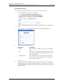
018
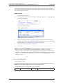
Figure 27.
Figure 19. Determine the IP address
4
Enter http://xxx.xxx.xxx.xxx (where xxx.xxx.xxx.xxx is the determined IP address) in
the browser address field to access the GUI.
5
After the first startup of the IPBS/IPBL the DHCP mode should be changed from
"automatic" to either "client" or "off", see 8.2.1 Set DHCP Mode on page 57.
7.2.2
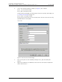
Change the Default Password
1
Enter the IP address determined in 7.2.1 Determine the IP Address in the web
browser address field.
2
Select General > Admin.
3
Enter user name and password in the dialogue box.
Default user name is: admin.
Default password is: changeme.
4
Enter a user name in the User Name text field.
5
Enter a password in the Password text field. Repeat the password in the second text
field.
6
Click "OK".
2009-04-15/ Ver. B
33
Installation and Operation Manual
IP-DECT Base Station & IP-DECT Gateway (software version 3.0.x)
7.3
TD 92579GB
GUI Web Access
7.3.1
Login Page
When accessing IPBS/IPBL through a web browser the initial page is the login page. This
page has two hyperlinks: System Administration and User Administration.
7.3.2
Access Levels
Three types of web users (or Access Levels) are authorized to access IPBS/IPBL:
• Auditors
• User Administrators
• System Administrators
The different types of access levels are described in the following table.
Access Level
Authorization
Login
hyperlink on
login page a
Described in
section
Auditors
• Read access to device parameter
settings
• Can generate Service Reports
System
Administration
7.3.3 Auditors
User
Administration
7.3.4 User
Administrators
on page 34
System
System
• Write access to all device
Administrators parameter settings (for example IP Administration
addresses, software upgrades)
• Assign and modify access to other
System Administrator and User
Administrator account settings
• Add, update and remove users
7.3.5 System
Administrators
on page 35
User
• Add, update and remove users
Administrators
a.Different users should use the hyperlink related to their access level. The system does not allow login by a link not
related to the user’s access level.
7.3.3
Auditors
Auditors have read access to device parameter settings but are not authorized to update
those settings. Auditors are also allowed to generate Service Reports (Administration >
Diagnostics > Service Reports).
The login steps for a auditor follow the steps of a normal system administrator login. See
7.3.5 System Administrators on page 35 for more information.
7.3.4
User Administrators
IPBS/IPBL is not supplied with preinstalled user administration accounts. Therefore, the first
user administration account must be created by a system administrator (see 7.3.5 System
Administrators on page 35). If additional user administration accounts are needed they
must also be created by a system administrator. Refer to Managing User Administrators on
page 37 for more information.
User administrators can only administer users. They can view but not create or manage
other user administrator accounts.
2009-04-15/ Ver. B
34
Installation and Operation Manual
IP-DECT Base Station & IP-DECT Gateway (software version 3.0.x)
TD 92579GB
Login as User Administrator
To login as a user administrator:
1
Follow 7.2 Access the GUI on page 31 and access the device using a web browser.
2
Click the link labelled User Administration.
A login window is opened.
3
Enter user name and password for a user administrator.
4
Click "OK" to login.
5
Click the show link.
6
The User Administration page is displayed.
See the figure below for a sample.
Figure 28.
Figure 20. User Administration Page Sample
The right side of the page consists of two list sections:
• User Administrators in the upper right section. Note: this section is read-only since a
user administrator cannot manage other user administrators. See Managing User
Administrators on page 37.
• Users in the lower right section. Refer to 7.12 Add Users on page 43.
7.3.5
System Administrators
IPBS/IPBL devices are factory delived with a default system administrator account.
Login as System Administrator
To login as a system administrator:
1
Follow 7.2 Access the GUI on page 31 and access the device using a web browser.
2
Click the link labelled System Administration.
A login window is opened.
3
Enter user name and password for a system administrator.
4
Click "OK" to login.
2009-04-15/ Ver. B
35
Installation and Operation Manual
IP-DECT Base Station & IP-DECT Gateway (software version 3.0.x)
5
TD 92579GB
Click on the Admin tab.
The Administration page is displayed. See the figure below for a sample
Figure 29.
Figure 21. System Administrator Admin Page
This page is used for the following tasks.
• Managing the default System Administrator account, see Admin Section on page 36.
• Managing additional System Administrator accounts, see Additional Administrator
Accounts on page 36.
Admin Section
The Admin section (the upper part of the page) displays the default System Administrator
account. This account can be modified (see the following section) but cannot be deleted.
Modify Admin Account
1
Login as system administrator (see Login as System Administrator).
1
Select Configuration > Admin.
2
Select/Enter the following settings:
Field name
Description
• Device Name
Enter a description for the device.
• User Name
Enter a login user name.
• Password
Enter a password.
• Confirm Password
Confirm the password.
Note: Only changing the password will not result in the settings being saved. For
the settings to be saved, both user name and password must be updated at the
same time!
3
Click "OK".
Additional Administrator Accounts
The Additional Administrator Account section (the lower part of the page) displays a list of
existing additional system administrator accounts.
Create An Additional Account
To create an additional administrator account do the following:
1
Login as system administrator (see Login as System Administrator on page 35).
2
Select Configuration > Admin.
2009-04-15/ Ver. B
36
Installation and Operation Manual
IP-DECT Base Station & IP-DECT Gateway (software version 3.0.x)
3
TD 92579GB
On the next free account row:
•
•
•
•
4
Enter User Name
Enter Password
Enter Password again
Select Administrator (for System Administrator) or Auditor in the drop-down list
(See 7.3.2 Access Levels on page 34 for a description of access levels.)
Click "OK".
The account row is created.
Modify An Additional Account
To modify an additional administrator account do the following:
1
Login as system administrator (see Login as System Administrator on page 35).
2
Select Configuration > Admin.
3
On an existing account row:
•
•
•
•
4
Enter a new user name
Enter a new password
Enter the password again
Select Administrator (for System Administrator) or Auditor in the drop-down list
(See 7.3.2 Access Levels on page 34 for a description of access levels.)
Click "OK".
The account row is updated.
Delete An Additional Account
To delete an additional administrator account do the following:
1
Login as system administrator (see Login as System Administrator on page 35).
2
Select Configuration > Admin.
3
On the row to be deleted, select the Delete check box.
4
Click "OK".
The account row is deleted.
Managing User Administrators
Create a User Administrator
IPBS/IPBL is not supplied with preinstalled user administration accounts. Therefore, the first
user administration account must be created by a system administrator. If additional user
administration accounts are needed they must also be created by a system administrator.
1
Login as System Administrator (see Login as System Administrator on page 35).
2
Select Administration > Users.
3
Click the show hyperlink.
The User Administration page (see figure 20 on page 35 for a sample) is displayed.
4
Click the new hyperlink. A window is opened.
5
Select the User Administrator radio box. The window layout transforms.
6
Enter a long name.
7
Enter a name (Note: This field is used for login).
2009-04-15/ Ver. B
37
Installation and Operation Manual
IP-DECT Base Station & IP-DECT Gateway (software version 3.0.x)
8
Enter a password.
9
Confirm the password.
10
Select "Administration of All Users" in the Rights drop-down list.
11
Click "OK".
TD 92579GB
View and Modify a User Administrator
1
Login as System Administrator (see 7.3.5 System Administrators on page 35).
2
Select Administration > Users.
3
Click on show.
A two-part list page is displayed. At the top are the user administrator accounts and
below the user administrators are the user accounts, both listed in alphabetical
order.
4
In the User Administrators section, click on a hyperlink below the Long Name
heading. A detail window is opened.
5
Select/Edit any of the following settings:
6
• Long Name
• Name (Note: This field is used for login)
• Password
• Confirm Password
• Rights
Click "OK".
Delete a User Administrator
1
Login as System Administrator (see 7.3.5 System Administrators on page 35).
2
Select Administration > Users.
3
Click on show.
4
In the User Administrators section, click on a hyperlink below the Long Name
heading. A detail window details for is opened.
5
Click on "Delete".
The User Administrator is deleted and the windows is closed.
7.4
Configure the Mobility Master
In a system with two or more Masters (Multiple Master system), a Mobility Master must be
configured. For more information on Multiple Master Systems, see the document System
Planning, Ascom IP-DECT System, TD 92422GB.
This section describes how to configure the Mobility Master. Each configuration step is
briefly described in the step list below. For more detailed information see the
corresponding subsection in 8 Operation on page 46.
1
Determine the address and access the GUI, see 7.2 Access the GUI on page 31.
2
Change the default password, see 7.2.2 Change the Default Password on page 33.
3
Set a static IP address and set DHCP to off, see 8.2.2 Set a Static IP Address on page
57.
4
Set the mode to Mobility Master, see 8.5.17 Select Mobility Master Mode on page
73.
2009-04-15/ Ver. B
38
Installation and Operation Manual
IP-DECT Base Station & IP-DECT Gateway (software version 3.0.x)
7.5
TD 92579GB
5
Write a login name and enter a password, see 8.5.17 Select Mobility Master Mode
on page 73.
6
Connect to other Mobility Master(s), see 8.5.18 Connect Mobilty Master to other
Mobility Master(s) on page 73.
7
Enter the Time Server address, see 8.1.4 Configure the NTP Settings on page 48.
8
Reset in order to make the configuration changes take effect, see 8.16 Reset on
page 113.
Configure the Standby Mobility Master
It is recommended to have a Standby Mobilty Master in a Multiple Master IP-DECT system.
This section describes how to configure the Standby Mobility Master. Each configuration
step is briefly described in the step list below. For more detailed information see the
corresponding subsection in 8 Operation on page 46.
7.6
1
Determine the address and access the GUI, see 7.2 Access the GUI on page 31.
2
Change the default password, see 7.2.2 Change the Default Password on page 33.
3
Set a static IP address and set DHCP to off, see 8.2.2 Set a Static IP Address on page
57.
4
Set the mode to Standby Mobility Master, see 8.5.17 Select Mobility Master Mode
on page 73.
5
Enter the primary Mobility Master IP address, see8.5.17 Select Mobility Master
Mode on page 73.
6
Write a login name and enter a password, this must be the same as in the primary
Mobility Master. See 8.5.17 Select Mobility Master Mode on page 73.
7
Connect to other Mobility Master(s). This should be the same Mobility Master(s) as
in the primary Mobility Master, see 8.5.18 Connect Mobilty Master to other
Mobility Master(s) on page 73.
8
Enter the Time Server address, see 8.1.4 Configure the NTP Settings on page 48.
9
Reset in order to make the configuration changes take effect, see 8.16 Reset on
page 113.
Configure the Pari Master
This section describes how to configure the Pari Master. Each configuration step is briefly
described in the step list below. For more detailed information see the corresponding
subsection in 8 Operation on page 46.
1
Determine the address and access the GUI, see 7.2 Access the GUI on page 31.
2
Change the default password, see 7.2.2 Change the Default Password on page 33.
3
Configure LDAP user name and password, select the Write Access check box, see
8.4.1 Configure LDAP Server on page 60.
4
Set a static IP address and set DHCP to off, see 8.2.2 Set a Static IP Address on page
57.
5
Set the mode to Master, see 8.5.12 Select Mode on page 70.
6
Perform a reset to restart the IPBS/IPBL in Master mode, see 8.16 Reset on page
113.
7
Select system name and password, see 8.5.1 Change System Name and Password
on page 66.
2009-04-15/ Ver. B
39
Installation and Operation Manual
IP-DECT Base Station & IP-DECT Gateway (software version 3.0.x)
7.7
TD 92579GB
8
Change subscription method, see 8.5.2 Change Subscription Method on page 67.
9
Configure authentication code, see 8.5.3 Configure Authentication Code on page
67.
10
Select tones, see 8.5.4 Select Tones on page 67.
11
Set default language, see 8.5.5 Set Default Language on page 67.
12
Set frequency band, see 8.5.6 Set Frequency Band on page 68.
13
Enable carriers, see 8.5.7 Enable Carriers on page 68.
14
Enable local R-key handling, see 8.5.8 Local R-Key Handling on page 68.
15
Enable No transfer on hangup, see 8.5.9 No Transfer on Hangup on page 68.
16
Configure coder, see 8.5.10 Configure Coder on page 69.
17
Select supplementary services, see 8.5.11 Configure Supplementary Services on
page 69.
18
Set Master Id, see 8.5.13 Set Master Id on page 71.
19
Enable Pari function, see 8.5.14 Enable Pari Function on page 71.
20
Enter gatekeeper IP address or ID, see 8.5.15 Configure Gatekeeper on page 71.
21
Connect to a Mobility Master, see 8.5.19 Connect Master to a Mobility Master on
page 73.
22
Assign PARI, see 8.5.23 PARI on page 74.
23
Enter SARI, see 8.5.24 SARI on page 75.
24
Enter IMS IP address, see 8.7.1 Configure Messaging on page 80.
25
Enter the Time Server address, see 8.1.4 Configure the NTP Settings on page 48.
26
Reset in order to make the configuration changes take effect, see 8.16 Reset on
page 113.
Configure the Standby Pari Master
It is recommended to have a Standby Pari Master in the IP-DECT system. This section
describes how to configure a Standby Pari Master. Each configuration step is briefly
described in the step list below, for more detailed information see the corresponding
subsection in 8 Operation on page 46.
1
Determine the address and access the GUI, see 7.2 Access the GUI on page 31
2
Change the default password, see 7.2.2 Change the Default Password on page 33.
3
Configure LDAP replicator, enter the IP address, user name and password to the
LDAP server (Pari Master). Alternative LDAP server must not be entered. Select the
Enable check box, see 8.4.3 Configure LDAP Replicator on page 61.
4
Set a static IP address and set DHCP to off, see 8.2.2 Set a Static IP Address on page
57.
5
Set the mode to Standby Master, see 8.5.12 Select Mode on page 70.
6
Perform a reset to restart the IPBS/IPBL in Standby Master mode, see 8.16 Reset on
page 113.
7
Enter system name and password, this should be the same system name and
password as in the Pari Master. see 8.5.1 Change System Name and Password on
page 66.
8
Select supplementary services, see 8.5.11 Configure Supplementary Services on
page 69.
2009-04-15/ Ver. B
40
Installation and Operation Manual
IP-DECT Base Station & IP-DECT Gateway (software version 3.0.x)
7.8
TD 92579GB
9
Set Master Id, see 8.5.13 Set Master Id on page 71.
10
Enable Pari function, see 8.5.14 Enable Pari Function on page 71.
11
Enter gatekeeper address, see 8.5.15 Configure Gatekeeper on page 71.
12
Connect to a Mobility Master, see 8.5.19 Connect Master to a Mobility Master on
page 73.
13
Enter IMS IP address, see 8.7.1 Configure Messaging on page 80.
14
Enter the Time Server address, see 8.1.4 Configure the NTP Settings on page 48.
15
Reset in order to make the configuration changes take effect, 8.16 Reset on page
113.
Configure the Master
This section describes how to configure the Master. Each configuration step is briefly
described in the step list below. For more detailed information see the corresponding
subsection in 8 Operation on page 46.
7.9
1
Determine the address and access the GUI, see 7.2 Access the GUI on page 31.
2
Change the default password, see 7.2.2 Change the Default Password on page 33.
3
Configure LDAP user name and password, select the Write Access check box, see
8.4.1 Configure LDAP Server on page 60.
4
Set a static IP address and set DHCP to off, see 8.2.2 Set a Static IP Address on page
57.
5
Set the mode to Master, see 8.5.12 Select Mode on page 70.
6
Perform a reset to restart the IPBS/IPBL in Master mode, see 8.16 Reset on page
113.
7
Select system name and password, see 8.5.1 Change System Name and Password
on page 66.
8
Set default language, see 8.5.5 Set Default Language on page 67.
9
Select supplementary services, see 8.5.11 Configure Supplementary Services on
page 69.
10
Set Master id, see 8.5.13 Set Master Id on page 71.
11
Enter gatekeeper IP address or ID, see 8.5.15 Configure Gatekeeper on page 71.
12
Connect to a Mobility Master, see 8.5.19 Connect Master to a Mobility Master on
page 73.
13
Enter IMS IP address, see 8.7.1 Configure Messaging on page 80.
14
Enter the Time Server address, see 8.1.4 Configure the NTP Settings on page 48.
15
Reset in order to make the configuration changes take effect, see 8.16 Reset on
page 113.
Configure the Standby Master
It is recommended to have a Standby Master in the IP-DECT system. This section describes
how to configure a Standby Master. Each configuration step is briefly described in the step
list below, for more detailed information see the corresponding subsection in 8 Operation
on page 46.
1
Determine the address and access the GUI, see 7.2 Access the GUI on page 31.
2
Change the default password, see 7.2.2 Change the Default Password on page 33.
2009-04-15/ Ver. B
41
Installation and Operation Manual
IP-DECT Base Station & IP-DECT Gateway (software version 3.0.x)
TD 92579GB
3
Configure LDAP replicator, enter the IP address, user name and password to the
LDAP server. Alternative LDAP server must not be entered. Select the Enable check
box, see 8.4.3 Configure LDAP Replicator on page 61.
4
Set a static IP address and set DHCP to off, see 8.2.2 Set a Static IP Address on page
57.
5
Set the mode to Standby Master, see 8.5.12 Select Mode on page 70.
6
Perform a reset to restart the IPBS/IPBL in Standby Master mode, see 8.16 Reset on
page 113.
7
Enter system name and password, this should be the same system name and
password as in the Master. See 8.5.1 Change System Name and Password on page
66.
8
Select supplementary services, see 8.5.11 Configure Supplementary Services on
page 69.
9
Set Master Id, see 8.5.13 Set Master Id on page 71.
10
Enter gatekeeper address, see 8.5.15 Configure Gatekeeper on page 71.
11
Connect to a Mobility Master, see 8.5.19 Connect Master to a Mobility Master on
page 73.
12
Enter IMS IP address, see 8.7.1 Configure Messaging on page 80.
13
Enter the Time Server address, see 8.1.4 Configure the NTP Settings on page 48.
14
Reset in order to make the configuration changes take effect, see 8.16 Reset on
page 113.
7.10 Plug and Play Configuration
Radios can be configured from the relevant Pari Master. When a new Radio is connected
to the system, it automatically registers itself as an uninitialized registration to all Pari
Masters in the system. It is possible to assign the Radio to one Pari Master. See Add Radios
on page 83.
7.11 Configure the Radio
This section describes how to configure the Radio. Each configuration step is briefly
described in the step list below, for more detailed information see the corresponding
subsection in 8 Operation on page 46.
Note: When one Radio is configured, the configuration can be saved and uploaded to the
other Radios in the system.
1
Determine the address and access the GUI, see 7.2 Access the GUI on page 31.
2
Change the default password, see 7.2.2 Change the Default Password on page 33.
3
Set DHCP mode to "Client", see 8.2.3 Dynamic IP address via DHCP on page 58.
4
Enable the Radio in the IPBS/IPBL, see
5
Enter Pari Master and Standby Pari Master IP addresses, see 8.5.21 Enter IP Address
to the Pari Master and the Standby Pari Master on page 74.
6
Configure air synchronization, see 8.5.25 Configure Air Synchronization on page
75.
7
Enter the Time Server address, see 8.1.4 Configure the NTP Settings on page 48.
2009-04-15/ Ver. B
42
Installation and Operation Manual
IP-DECT Base Station & IP-DECT Gateway (software version 3.0.x)
TD 92579GB
8
Reset in order to make the configuration changes take effect, see 8.16 Reset on
page 113.
9
Save the configuration of the Radio, see 8.12 Backup on page 103.
Configure the rest of the IPBS/IPBLs following the steps below:
Note: Uploading the same configuration to all Radios can only be done if the DHCP is set
to client.
1
Determine the address.
2
Select Update > Config and browse to the previously saved configuration. Click
"OK".
3
Reset in order to make the configuration changes take effect, see 8.16 Reset on
page 113.
4
Repeat step 1 to 3 for all Radios.
7.12 Add Users
This section describes how to add users to the IP-DECT system. There are two ways to
register Portable Devices:
• Using the Portable Device to automatically associate the IPEI number to a user, see
7.12.1 Anonymous Registration on page 43.
• Entering the IPEI number of the Portable Device manually, see 7.12.2 Individual
Registration on page 44.
7.12.1 Anonymous Registration
The IPEI, which is the unique identification number of the Portable Device, can be assigned
automatically to a user. This is used to avoid having to enter the IPEI number manually.
Add users in the IP-DECT System
1
Under the Administration menu, select Users.
2
Click "New".
3
Enter the following information in the corresponding text fields, leave the IPEI and
the Auth. Code text fields empty:
• Long Name - The name of the user, need to be unique throughout the system.
This is the name presented in a called party´s display, unless this is configured in
the IP-PBX.
• Name - The user name.
• Number - The phone number extension, need to be unique throughout the
system.
• Password - Optional, is used for registration towards the gatekeeper.
• Display Name - Will be showed in the Portable Device display when the Portable
Device is idle.
4
Click "OK".
5
Repeat step 2 to 4 for all users.
Assign Portable Devices to Users
1
2009-04-15/ Ver. B
Select DECT > System.
43
Installation and Operation Manual
IP-DECT Base Station & IP-DECT Gateway (software version 3.0.x)
TD 92579GB
2
Enable anonymous registration by selecting "With System AC" in the Subscriptions
drop-down list.
3
Click "OK".
4
Perform an "over air subscription" using the system Authentication Code. For
information on how this is done, see the reference guide of the Portable Device.
The Portable Devices’ IPEI number appears in the Anonymous list. To view the list:
Select Users > Anonymous.
5
Assign the Portable Device to any user, subscribed or unsubscribed, on any Master
defined in the system by calling the desired Master id & extension & optional
individual AC code and hang up.
Example where 0 is the Master id, 200 is the extension and 1234 is the AC code:
*0*200*1234#
Note: When using AC code, start with * and end with # character. Otherwise skip
the *# characters. If the user is already assigned to a Portable Device, it will be
moved to the anonymous list when logging in a new Portable Device.
6
Repeat step 4 to 6 for all Portable Devices.
7
Under the Configuration menu, select DECT > System.
8
Disable anonymous registration by selecting "Disable" in the Subscription dropdown list.
9
Click "OK".
7.12.2 Individual Registration
1
Select Users.
2
Click "New".
3
Enter the following information in the corresponding text fields:
• Long Name - The name of the user, need to be unique throughout the system.
This is the name presented in a called party´s display, unless this is configured in
the IP-PBX.
• Name - The user name.
• Number - The phone number extension, need to be unique throughout the
system.
• Password - Optional, is used for registration towards the gatekeeper.
• Display Name - Will be showed in the Portable Device display when the Portable
Device is idle.
• IPEI - The unique identification number of the Portable Device.
• Auth. Code - The individual authentication code for this user.
4
Perform an "over air subscription" using the individual authentication code. For
information on how this is done, see the reference guide of the Portable Device.
5
Click "OK".
7.13 Logout/Login Users
This section describes how to logout and login users to the Ascom IP-DECT system. For
example, when using a shared Portable Device for shift workers.
7.13.1 Logout Users
Logout the Portable Device for any subscribed user in the system by calling the
supplementary services feature for logout (see 8.5.11 Configure Supplementary Services
2009-04-15/ Ver. B
44
Installation and Operation Manual
IP-DECT Base Station & IP-DECT Gateway (software version 3.0.x)
TD 92579GB
on page 69) & optional individual AC code and hang up.
Example where #11*$# is the feature for logout and 1234 is the AC code: #11*1234#.
7.13.2 Login Users
To login a user, see Assign Portable Devices to Users on page 43.
2009-04-15/ Ver. B
45
Installation and Operation Manual
IP-DECT Base Station & IP-DECT Gateway (software version 3.0.x)
8
TD 92579GB
Operation
This section describes the settings in the Configuration and Administration menu, each
subsection represents a sub menu to the Configuration and Administration menu.
Some changes require a reset in order to take effect. It is possible to do several changes
before resetting the IPBS/IPBL.
The GUI for the IPBS and IPBL are similar. Screen shots from the IPBS are used as default.
8.1
General
This section describes how to do the following configurations and settings.
•
•
•
•
•
•
Change User Name and Password
Name the equipment
Configure automatic firmware update
Configure the NTP settings
Configure Logging
Configure the HTTP settings
Figure 30.
Figure 22. Assigning a name, username, and password.
8.1.1
Change User Name and Password
The user name and password us used to access the IPBS/IPBL through the web GUI.
1
Select General > Admin.
2
Write a user name in the User Name text field.
3
Enter a new password in the Password text field. Repeat the password in the
second text field.
4
Click "OK".
8.1.2
Name the IPBS/IPBL
Each IPBS/IPBL can be assigned a name. It is recommended to assign a descriptive name
for example IPBS/IPBL location.
2009-04-15/ Ver. B
46
Installation and Operation Manual
IP-DECT Base Station & IP-DECT Gateway (software version 3.0.x)
1
Select General > Admin.
2
Enter a name in the Device Name text field.
3
Click "OK".
8.1.3
TD 92579GB
Configure Automatic Firmware Update
The IPBS/IPBL can be configured to automatically update its firmware. A script file must be
uploaded to a suitable directory on an internal web server. For information on the script
file syntax, see Appendix A: How to Use the Update Server on page 121.
1
Select General > Update
2
Enter the URL of the script file in the URL text field.
3
Enter the poll interval, in minutes, in the Interval (min) text field
4
Click "OK".
The Current Update Serials section shows the values of the variables set after the last
execution of the associated command.
2009-04-15/ Ver. B
47
Installation and Operation Manual
IP-DECT Base Station & IP-DECT Gateway (software version 3.0.x)
8.1.4
TD 92579GB
Configure the NTP Settings
Since the IPBS/IPBL does not have a battery-backed real-time clock, the internal time will
be set to 0:00 hrs, 1.1.1970 in the case of a restart.
In order to get the correct time in the system, specify the IP address of a NTP time server.
The IPBS/IPBL will synchronize its internal clock to the time server at startup and at the
specified intervals. The clock is, for example, used by the handsets and log files.
Figure 23. Configure NTP settings
1
Select General > NTP.
2
Enter the IP address to the NTP server.
3
Enter a time interval in the Interval (min) text field.
4
Select time zone in Time zone drop-down list. If the desired time zone is not in the
list, select “Other” and edit the String text field following the instructions in the
next step.
5
Enter the timezone string if automatically updates summer/winter is desired.
<String = StdOffset [Dst[Offset], Date/Time, Date/Time]>
• Std = Time zone (for example EST for Eastern Standard Time).
• Offset = time difference between the timezone and the UTC (Universal Time
Coordinator).
• Dst = summertime zone (for example EDT for Eastern Daylight Time).
• Second Offset = time difference between the summer time and the UTC.
• Date/ Time, Date/ Time = beginning and end of summertime.
- date format = Mm.n.d (d day of n week in the m month)
- time format = hh:mm:ss in 24-hour format.
Note that a week always starts on a Sunday and the number for Sunday is 0.
Example:
North Carolina is located in the Eastern Time Zone. Eastern Standard Time (EST) is 5
hours behind UTC (StdOffset = EST-5), the Eastern Daylight Time (EDT) is 4 hours
behind UTC (DstOffset = EDT-4). Summertime for the year 2006 begins at two a
clock, on a Sunday, the first week in April (M4.1.0/2). The summertime ends at two
a clock, on a Sunday, the fifth week in October (M10.5.0/2).
2009-04-15/ Ver. B
48
Installation and Operation Manual
IP-DECT Base Station & IP-DECT Gateway (software version 3.0.x)
TD 92579GB
<String = EST-5EDT-4,M4.1.0/2,M10.5.0/2>
6
8.1.5
Click “OK”.
Configure Logging
There are three ways to collect logs, see the table below.
Figure 31.
TCP
The syslog entries are transmitted using a TCP connection.
SYSLOG
The entries are reported to a “syslogd” server in the network,
which is responsible for further evaluation or storage of the
entries.
HTTP
The syslog entries are transferred to a web server where they
can be further processed. Each individual syslog entry is
transmitted as form data to the web server in HTTP GET
format.
Store the Syslog Entries using a TCP Connection
1
Select General > Logging
2
Select "TCP" in the Type drop-down list.
3
Enter the "IP address" of the logging server in the Address text field.
4
Enter the "Port" of the logging server in the Port text field.
5
Click "OK".
Store the Syslog Entries in a Syslogd
1
Select General > Logging.
2
Select “SYSLOG” in the Type drop-down list.
3
Enter the “IP address” of the syslogd in the Address text field.
4
Enter the desired syslogd message class in the Class text field.
5
Click “OK”.
Store the Syslog Entries on a Web Server
1
Select General > Logging.
2
Select “HTTP” in the Type drop-down list.
3
Enter the “IP address” in the Address text field.
4
Enter the "Port" in the Port text field.
5
Enter the “relative URL of the form programme” on your web server in the Path
text field.
6
Click “OK”.
Note: The IPBS/IPBL will make an HTTP GET request to the web server on the registered
URL followed by the URL-encoded log entry.
Example:
Enter the value “/cdr/ cdrwrite.asp” in the “URL-Path” field if a page is on the web server
with the name “/cdr/cdrwrite.asp” with a form that expects the log message in the “msg”
2009-04-15/ Ver. B
49
Installation and Operation Manual
IP-DECT Base Station & IP-DECT Gateway (software version 3.0.x)
TD 92579GB
parameter. In this example, the IPBS/IPBL will make a GET /cdr/
cdrwrite.asp?event=syslog&msg=logmsg request to the server.
Forward Alarms and Events
It is possible to forward alarms and events to an external server destination.
1
Select General > Logging.
2
Enter the IP Address of the IPBS/IPBL where you want to have an overview of all
faults in the External HTTP Server Address text field.
3
Enter the HTTP server port in the External HTTP Server Port text field. The default
value is 80.
8.1.6
Configure the HTTP settings
Traditionally IPBS/IPBL has been administered over the network via the http protocol
(default port 80).
In a secure system (see the IP Security chapter) IPBS/IPBL should be administered via the
https protocol (default port 443). If for some reason port 443 is not to be used, you can
use another port for the local https server and then access the IPBS/IPBL via this port.
Figure 24. Configure the HTTP Settings
1
Select General > HTTP
• Select the Force HTTPS check box to allow only HTTPS sessions and all HTTP
requests are redirected as HTTPS requests.
• Select the Disable HTTP basic authentication check box to require all
administrative and programmatic clients to support HTTP digest authentication.
• Select the Password protect all HTTP pages check box to password protect all
HTTP pages.
• Enter "Port number" in the Port text field. The IPBS/IPBL is by default
administered over the network via the TCP port 80 (http). If port 80 is not to be
used another port can be set up for access. Set this value to 0 to disable http
traffic (recommended). Attempts to contact the device using the http protocol
will result in an Unable to connect message.
• Enter "HTTPS Port" in the HTTPS Port text field. To access IPBS/IPBL securely, use
the TCP port 443 (https). Set this value to anything except zero (0) to enable
2009-04-15/ Ver. B
50
Installation and Operation Manual
IP-DECT Base Station & IP-DECT Gateway (software version 3.0.x)
TD 92579GB
https traffic. The default value is 443. The value zero (0) disables https traffic
which is not recommended.
• Enter "Network Base Adresss" / "Network Base Mask" in the Allowed stations
text fields to only allow access only from matching network, for
example:172.16.0.0/255.255.0.0
• In the Active HTTP sessions field all ongoing HTTP traffic is displayed.
Figure 32.
2
8.1.7
Click "OK".
Configure the HTTP Client settings
A list of URL that require authentication can be specified.
1
Select General > HTTP Client.
2
Enter the “URL” in the URL text field.
3
Enter "User" and "Password" in the User and Password text fields.
4
Click “OK”.
A new row will be shown and more URLs can be added.
8.1.8
SNMP
Faults can be reported in the IP-DECT system via the Simple Network Management
Protocol (SNMP). The SNMP framework has three parts:
• An SNMP manager: the system used to control and monitor the activities of network
hosts using SNMP.
• An SNMP agent: the software component within the managed device that maintains
data for the device and reports data, as needed, to managing systems.
• A MIB: The Management Information Base (MIB) is a virtual information storage area
for network management information.
The agent and MIB reside on a network device (for example, router, access server, or
switch). To enable the SNMP agent on the IPBS/IPBL, the relationship between the
manager and the agent must be defined.
Figure 25. Configure SNMP Settings
1
2009-04-15/ Ver. B
Select General > SNMP
51
Installation and Operation Manual
IP-DECT Base Station & IP-DECT Gateway (software version 3.0.x)
TD 92579GB
2
Enter a name in the Community field if you are not using the standard community
name (public). The community text string acts like a password to regulate access to
the agent on the Base Station.
3
Enter a device name in the Device Name field. This field is optional and serves only
informational purposes.
4
Enter the name and phone number of the contact person in the Contact field. This
field is optional and serves only informational purposes.
5
Enter a location in the Location field. This field is optional and serves only
informational purposes.
6
Select the Authentification Trap check box to enable the sending of authentification
traps. Access via SNMP is only possible if the correct Community Name is entered. If
enabled a trap will be generated in the event of access with an incorrect
Community Name.
7
Enter the IP address of the desired trap destinations in the Trap Destinations field.
SNMP traps will be sent to all destinations.
8
Enter the IP address and mask of the networks that are allowed to send SNMP
requests. All networks are allowed if the field is empty.
9
Click "OK".
8.1.9
Certificates
The Certificates tab is part of IP Security in IP-DECT. For more information on IP Security,
see chapter 4 IP Security on page 14.
Select Configuration > General > Certificates.
Figure 33.
As described in Certificate Handling Options on page 16, there are three possible
certificate options:
1
Default device certificate, see Default Device Certificate on page 53.
2
Self-signed certificates, see Self-signed Certificates on page 54.
3
Certificates signed by a Certificate Authority (CA), see Certificate Signing Request
(CSR) on page 55.
The following table describles the different functions.
2009-04-15/ Ver. B
Field name
Description
• Subject
Click the hyperlink (under the Subject header) to display
certificate details in a window.
• PEM
Click the PEM hyperlink (under the Download header) to
download the certificate in PEM format.
• DER
Click the DER hyperlink (under the Download header) to
download the certificate in DER format.
52
Installation and Operation Manual
IP-DECT Base Station & IP-DECT Gateway (software version 3.0.x)
TD 92579GB
• Create New
The Create New hyperlink is used for two purposes:
• Self-signed Certificates on page 54
• Certificate Signing Request (CSR) on page
55
• Upload
Use the Upload function to upload a certificate file to the
device.
1
Click the Browse button
2
Select a certificate file
3
Click the Upload button to upload the
file to the device.
Note: The Upload function requires a previously issued CSR
to exist.
Default Device Certificate
This section corresponds to option 1 in Certificate Handling Options on page 16.
If the default device certificate is missing for the device it will be generated, together with
a key pair, when the IPBS is upgraded to version R3. The default certificate contains the
MAC address of the device and will be valid for 10 years.
If the self-signed certificate is deleted and the device is restarted, a new certificate and key
pair will be generated.
HTTPS is deactivated during the generation (creation) of the certificate.
The default certificate is a self-signed certificate. This means that certificates cannot be
verified and thus the user/administrator will be prompted by the web browser to accept
the certificate before it can be used. From this point on within the browser session (as long
as the certificate is not changed) communication between the browser and the device is
possible without further accept operations from the user/administrator.
If the device certificate is replaced or regenerated the user/administrator has to manually
accept the new certificate.
2009-04-15/ Ver. B
53
Installation and Operation Manual
IP-DECT Base Station & IP-DECT Gateway (software version 3.0.x)
TD 92579GB
Self-signed Certificates
This section corresponds to option 2 in 4.2.2 TLS Certificates on page 16.
1
Select Configuration > General > Certificates.
Figure 34.
2
Click the Create New hyperlink in the Device Certificate section. A window will
open.
3
In the window, select “Self-signed certificate” in the Type drop-down list.
Figure 35.
4
Select/Enter the following settings:
Field name
Description
• Validity
Enter the default validity in years. This is a mandatory
field.
• Key
Select either the desired key strength (1024-bit, 2048bit, 4096-bit) or select to reuse the old key pair (this is
not recommended).
• Common Name
Enter the domain name or IP address for the device.
This is the same value as entered in the web browser
when accessing the device.
5
Click “OK”.
6
A new key pair and a certificate will be created. This may take up to one hour
depending on the key strength selected. During this time the device will be fully
operational with the exception of https not working and the certificate tab pane
not being visible.
2009-04-15/ Ver. B
54
Installation and Operation Manual
IP-DECT Base Station & IP-DECT Gateway (software version 3.0.x)
TD 92579GB
Certificate Signing Request (CSR)
This section corresponds to option 3A & 3B in 4.2.2 TLS Certificates on page 16. This will
be the most common options for IP-DECT systems. For more information on CSRs see
Certificate Authorities on page 14.
1
Select Configuration > General > Certificates.
2
Click the Create New hyperlink in the Device Certificate section. A window will
open.
Figure 36.
3
In the window, select “Signing Request” in the Type drop-down list.
4
Select/Enter the following settings:
5
Field name
Description
• Validity
This is an read-only information field indicating a
default mandatory validity of 1 year. The time length of
the validity is defined by the CA.
• Key
Select the desired key strength (1024-bit, 2048-bit,
4096-bit) or select to reuse the old key pair (this is not
recommended).
• Common Name
Enter the domain name or IP address for the device.
This is the same value as entered in the web browser
when accessing the device.
Click “OK”. The windows closes.
A key pair and a CSR file will be created. This may take up to one hour depending
on the key strength selected. During this time the device will be fully operational
with the exception of https not working and the certificate tab pane not being
visible.
When the CSR file has been generated it is visible in the Signing Request section of
the Certificates page.
6
Download the CSR file by clicking the PEM or DER link in the Signing Request
section.
7
Send the CSR file to your CA.
8
If successful your CA will send back a digitally signed certificate file. This file should
now be uploaded.
9
Select the certificate file.
10
Click "Upload".
2009-04-15/ Ver. B
55
Installation and Operation Manual
IP-DECT Base Station & IP-DECT Gateway (software version 3.0.x)
TD 92579GB
Note: If the CSR file generated in step 5 is deleted before receiving the reply from the CA
(in step 8) it will not be possible to upload the signed certificate file in step 10. The system
will automatically delete the CSR file when step 10 has completed.
2009-04-15/ Ver. B
56
Installation and Operation Manual
IP-DECT Base Station & IP-DECT Gateway (software version 3.0.x)
8.2
TD 92579GB
LAN
This section describes how to do the following configurations and settings.
•
•
•
•
•
•
Set DHCP mode
Set IP static address
Set dynamic IP address
Set link type
Configure VLAN
View LAN statistics
Note: The IPBL has two LAN ports. LAN1 port must be used in the IP-DECT system (LAN2
port is for administration only).
8.2.1
Set DHCP Mode
The IPBS/IPBL can have different DHCP modes, see the table below.
Figure 37.
Disabled
Used if the IPBS/IPBL should have a static IP address.
Client
The IPBS/IPBL acts as a DHCP Client, if there is a DHCP server in
the network it will be assigned an IP address
Automatic
In automatic DHCP mode the IPBS/IPBL will act as a DHCP
client on power up.
If the IPBS/IPBL is restarted by shortly pressing the reset button
it will get the IP address 192.168.0.1 and the netmask
255.255.255.0 for the LAN1 port.
Change DCHP mode following the steps below.
1
Select LAN > DHCP.
2
Select DHCP mode in the Mode drop-down list.
3
Click “OK”.
4
Reset in order to make the changes take effect if "Client" or "Automatic" is set,
see 8.16 Reset on page 113.
8.2.2
Set a Static IP Address
It is necessary for the Master and the Standby Master to have static IP addresses. The
Radios can have dynamic IP addresses retrieved from the network DHCP server.
Ask the network administrator to reserve an IP address for the Master and Standby Master.
1
Select LAN > DHCP.
2
Select “Disabled” in the Mode drop-down list.
3
Click “OK”.
4
Do NOT reset the device yet. Set a static IP address first.
5
Select LAN > IP.
6
Enter "IP Address", "Network Mask", "Default Gateway" and "DNS Server"
addresses provided by the network administrator in the text fields.
You can also enter an alternative DNS Server in the Alt. DNS Server text field and
select the Check ARP check box to detect and prevent ARP poisoning attacks.
2009-04-15/ Ver. B
57
Installation and Operation Manual
IP-DECT Base Station & IP-DECT Gateway (software version 3.0.x)
TD 92579GB
7
Click “OK”.
8
Reset in order to make the changes take effect, see 8.16 Reset on page 113.
9
Start the web-based configuration, using the static IP address.
8.2.3
Dynamic IP address via DHCP
The Radios can have dynamic IP address allocation if the network has an DHCP server.
1
Select LAN > DHCP.
2
Select “Client” in the Mode drop-down list.
3
Click “OK”.
4
Reset in order to make the changes take effect, see 8.16 Reset on page 113.
Note: If the DHCP lease time is shorter than the time-to-live of the name/IP address
association in the Windows Internet Name Service (WINS) server, it may cause a mismatch,
and a wrong device may be reached if its WINS name is used.
8.2.4
Link
The link setting should be set to "auto" under all normal circumstances.
8.2.5
Configure VLAN
Identity and priority settings for VLAN are done in the "LAN > VLAN" sub menu.
Note: It is necessary to have a VLAN with the same ID as configured in the IPBS/IPBL
otherwise it will not be possible to access the IPBS/IPBL.
8.2.6
View LAN Statistics
To view statistics of LAN events: Select LAN > Statistics
To reset the ethernet statistics counters: Click the clear-stat button.
2009-04-15/ Ver. B
58
Installation and Operation Manual
IP-DECT Base Station & IP-DECT Gateway (software version 3.0.x)
8.3
TD 92579GB
IP
8.3.1
Configure IP Settings
The following settings can be done in the IP settings sub menu:
ToS priority,
RTP Data and VoIP Signalling:
Determines the priority from the ToS field in the IP
header. This function can be used if the router can
use ToS priority control.
Hexadecimal, octal or decimal values can be used;
0x10, 020 and 16 are all equivalent.
There are two fields for ToS priority, one for RTP
Data and one for VoIP Signallinga. Other types of
traffic (for example http and ldap) are not prioritized
and use 0x00.
Note: Remember that the same value should be set
in the ToS field for all devices.
RTP ports:
If the ports fields are left blank, the ports 16384 to
32767 will be used.
a. VoIP Signalling includes roaming, handover, registrations towards the IP-PBX etc.
1
Select IP > Settings.
2
Enter the ToS priority value (recommended value is "0xb8") in the ToS Priority - RTP
Data text field.
3
Enter the ToS priority value (recommended value is "0x68") in the ToS Priority - VoIP
Signalling text field.
4
Select which ports to use for RTP traffic by entering the first port in the First UDPRTP Port text field.
5
Enter the number of ports to use in the Number of Ports text field.
6
Click "OK".
8.3.2
Routing
View the IP routing by Select IP > Routing.
8.4
LDAP
The Lightweight Directory Access Protocol (LDAP) protocol is required for systems in which
the server and a replicating client access a joint user database.
The joint user database contains information about the users registered in the system. It
also contains the system configuration, that is the configurations made under the "DECT"
menu.
This section describes how to do the following configurations and settings.
•
•
•
•
Configure LDAP Server
Check LDAP Server Status
Configure LDAP Replicator
Check LDAP Replicator Status
2009-04-15/ Ver. B
59
Installation and Operation Manual
IP-DECT Base Station & IP-DECT Gateway (software version 3.0.x)
8.4.1
TD 92579GB
Configure LDAP Server
The IP-DECT system needs an LDAP server in some configurations. If the VoIP gateway is
setup as an LDAP server the Master should be setup as an LDAP replicator, see 8.4.3
Configure LDAP Replicator on page 61.
Setup the IPBS/IPBL as an LDAP server
Note: The selected user name and password must be the same in both the Master and the
Standby Master.
1
Select LDAP > Server.
2
Add a user, for example ldap-user, in the User text field.
3
Enter a password in the Password text field.
4
Select the Write Access check box.
5
Click "OK".
Figure 38.
Figure 26. Setting LDAP User Name and Password
8.4.2
Check LDAP Server Status
1
Select LDAP > Server Status
The following information can be checked:
•
•
•
•
•
•
•
•
•
•
•
connections - Total number of active connections to the LDAP server
write connections - Number of write-enabled connections
rx search - Number of received search requests
rx modify - Number of received change requests
rx add - Number of added objects
rx del - Number of deleted objects
rx abandon - Number of lost connections
tx notify - Number of sent change notifications
tx error - Number of sent error notifications
tx error 49 - Number of sent error notifications due to invalid credentials
tx error 50 - Number of sent error notifiatiosn due to insufficient access rights
2009-04-15/ Ver. B
60
Installation and Operation Manual
IP-DECT Base Station & IP-DECT Gateway (software version 3.0.x)
8.4.3
TD 92579GB
Configure LDAP Replicator
LDAP Replicators are usually configured in the following cases:
• User data is replicated from the Master to the Standby Master. The replicator is
configured on the Standby Master (Full Directory Replication)
• User data is replicated from the Active Directory (AD) to the Master. The replicator is
configured on the Master
• User data is replicated from the PBX to the Master. The replicator is configured on the
Master (Full Directory Replication)
Configure Full Directory Replication
1
Select LDAP > Replicator.
2
Select "Full Replication" in the Type drop-down list.
3
Select the Enable check box.
4
Enter the IP address to the LDAP server in the Server text field.
5
Enter the IP address to the alternative LDAP server in the Alt. Server text field.
Note: If this IPBS/IPBL is configured as a standby LDAP server, enter "0.0.0.0" in the
Alt. Server text field.
6
Select a filter method from the Filter Type drop-down list
• Dect Gateway Name - Enter the name of the DECT gateway to limit the
replication to users of a certain group
• LDAP Filter - Enter an LDAP filter to limit replication to certain LDAP objects
7
Enter the LDAP User name and Password in the User and Password text fields.
8
Click "OK".
Note: In the case of Master to Standby Master Full Directory Replication, do not register
new Portable Devices when the LDAP Server is down even if there is a Standby LDAP
Server in the system.
Configure Active Directory Replication
During Active Directory (AD) replication the configured LDAP replicator retrieves only
relevant data.
AD replication is a one-way replication where data is only transferred from the AD to the
IP-DECT but not from the IP-DECT to the AD. Data originating from the AD cannot be
modified in the IP-DECT system, but it is possible to change or add those user attributes
locally that are not replicated.
Note: If AD replication is enabled, existing local users are replaced with corresponding
users in the AD, and some local attributes may be deleted. Contact Ascom Technical
Support if you would like to enable AD replication with existing local users.
For AD Server configuration settings, see Configure AD Server on page 64.
1
Select LDAP > Replicator.
2
Select "Active Directory Replication" in the Type drop-down list.
3
Select the Enable check box.
4
Enter the IP address to the AD in the Server text field.
2009-04-15/ Ver. B
61
Installation and Operation Manual
IP-DECT Base Station & IP-DECT Gateway (software version 3.0.x)
5
TD 92579GB
Enter a Distinguished Name (DN) to configure a search base for AD users.
The user information is usually replicated so It is recommended to write "CN=Users,
DC=DomainName" where "DomainName" is the name of the domain on the AD
server.
You can also click "Show Options..." to see some naming contexts on the
configured server.
6
Enter an LDAP filter to retrieve only the relevant LDAP objects from the AD.
A default (objectclass=user) filter is offered, but it is recommended to assign all IPDECT users to a group within the AD. For example, the following filter can be
entered to retrieve only IP-DECT users.
"(&(objectClass=user)(memberOf=CN=grp_ipdect,CN=Users,DC=DomainName))"
where "grp_ipdect" is the group created for IP-DECT users, "Users" is the default
folder for users and "DomainName" is the name of the domain on the AD server.
7
Enter the user name and the password of a user who has read access to the AD in
the User and the Password text fields. It is recommended to choose a user with
Enterprise Administrator rights.
8
Configure In Maps and Out Maps for Attribute mapping. Attribute mapping
describes how the obtained information from the AD is handled within the IP-DECT
system. For more information see Attribute Mappings on page 62.
9
Click "OK".
10
After proper configuration check the Replicator Status by selecting LDAP >
Replicator Status. The state of the Active Directory Replication should be "Up" and
the state of the remote directory should be "Completed".
Figure 27. Configure Active Directory Replication
Attribute Mappings
The following attributes are generally used to configure attribute mappings:
2009-04-15/ Ver. B
62
Installation and Operation Manual
IP-DECT Base Station & IP-DECT Gateway (software version 3.0.x)
TD 92579GB
IP-DECT
designator
IP-DECT
attribute
name
AD attribute name
Description
Long Name
cn
cn
Common name, mandatory
and must be unique
Name
h323
userPrincipalName
User name
Number
e164
telephoneNumber,
ipPhone, mobile
Business or mobile phone
number, mandatory and
must be unique
Display
dn
displayName,
givenName, sn
Displayed name, first name
or surname
In Maps
In Maps define which attributes of the incoming objects are replicated and how the
attributes are used in the IP-DECT system. In Maps can be configured with the following
text fields:
• Source Attribute - The name of the AD attribute to be replicated. Only those users are
replicated who have the defined source attributes. See AD attribute name on page 63
for examples.
• Assignment Pattern - A regular expression that assigns AD attributes to local temporary
variables. A local temporary variable can have any name starting with a % sign, for
example %tel. Regular expressions are written in a formal language that is widely used
in Unix environments. For more information, see regular expression manuals on the
internet.
• Description - Short explanation of what is configured with regular expressions
If there are several in maps for one attribute, all maps are handled in the order of
appearance. To change the order of appearance click the "Move Up" or "Move Down"
icons on the left side of the In Maps window.
Out Maps
Out Maps define how the local temporary variables configured for In Maps are assigned to
the internal IP-DECT attributes. Out Maps can be configured with the following text fields:
• Dest. Attribute - The name of the IP-DECT attribute. See IP-DECT attribute name on
page 63 for examples.
• Destination Value - The name of the local temporary variable
2009-04-15/ Ver. B
63
Installation and Operation Manual
IP-DECT Base Station & IP-DECT Gateway (software version 3.0.x)
TD 92579GB
Example
Figure 28. Attribute mapping example
In the example above regular expressions are used to remove non-numerical characters
from the phone number (second line of In Maps). The third line of In Maps defines a local
temporary variable (dsp) which stores all numbers starting with 031 with "Gbg" added
before them. This is shown in the Display attribute as assigned in the Out Maps.
It is recommended to configure a default value for some attributes to avoid the retention
of old information in the IP-DECT database. In the example below the display attribute is
assigned an empty string if that attribute is not defined in the AD. The Source Attribute in
the third line of In Maps is cn because it should be an attribute that is always present in
the AD.
Example
Figure 29. Default value assignment
Configure AD Server
The IP-DECT system supports only simple binding authentication. However, the default
registry setting for Microsoft Active Directory 2003 does not allow simple binds, so it may
be necessary to change Windows Registry settings to use AD replication.
2009-04-15/ Ver. B
64
Installation and Operation Manual
IP-DECT Base Station & IP-DECT Gateway (software version 3.0.x)
TD 92579GB
1
In Windows, select "Run..." in the Start menu.
2
Enter "regedit" and click "OK" to start the Windows Registry Editor.
3
In the Editor go to the
"HKEY_LOCAL_MACHINE\SYSTEM\CurrentControlSet\Services\NTDS\Parameters\
LDAPServerIntegrity" key.
4
Click on the key with the right mouse button and click "Modify".
5
Change the key value of 2 to the value of 1.
6
Click "OK".
8.4.4
Check LDAP Replicator Status
1
Select LDAP > Replicator-Status.
The following information can be checked:
• Server - The IP address and port of the LDAP server.
• Active Directory Replication - Current state of replication. Four states are
possible: Stopped, Starting, Up, Down
• remote - State of replication in the source directory. Three states are possible:
Stopped, Active, Completed
• notify - Number of change notifications received from the server
• paged - Number of objects received from AD server in response to paged search
requests
• no match - Number of objects received that are not matching the configured
LDAP filter condition
• discarded - Number of objects discarded because no suitable map is found
• local - State of replication in the destination directory. Three states are possible:
Stopped, Active, Completed
• notify - Number of change notifications sent to the server
• add - Number of locally added objects
• del - Number of locally deleted objects
• modify - Number of locally modified objects
• pending - Number of local objects waiting to be sent to the server
8.4.5
Expert tool
The Expert function should only be used after consultation with Ascom Technical Support.
2009-04-15/ Ver. B
65
Installation and Operation Manual
IP-DECT Base Station & IP-DECT Gateway (software version 3.0.x)
8.5
TD 92579GB
DECT
This section describes how to do the following configurations and settings.
•
•
•
•
•
•
•
•
•
•
•
•
•
•
•
•
•
•
•
•
•
Change DECT user name and password
Change Subscription Method
Configure Authentication Code
Select Tone system
Set Default Language
Set Frequency Band
Enable/Disable Carriers
Enable/Disable Local R-Key Handling
Enable/Disable No Transfer on Hangup
Configure Coder
Configure Supplementary Services
Select Master Mode
Configure Gatekeeper
Select Mobility Master mode
Connect Mobilty Master to other Mobility Master(s)
Enable/Disable Radio
Enter IP address to the Pari Master and the Standby Pari Master
Multiple Radio Configuration
Assign PARI
Enter SARI
Configure Air Synchronization
Figure 39.
Figure 30. The DECT System configuration page
8.5.1
Change System Name and Password
The system name and password must be the same for all IPBS/IPBLs throughout the
system. Reset in order to make the changes take effect, see 8.16 Reset on page 113.
2009-04-15/ Ver. B
66
Installation and Operation Manual
IP-DECT Base Station & IP-DECT Gateway (software version 3.0.x)
TD 92579GB
Note: If Ascom VoIP Gateway is the LDAP server, the password in the IPBS/IPBL must be
identical to the Ascom VoIP Gateway (PBX/Password).
1
Select DECT > System.
Note: To access the System tab, the Master mode has to be activated, see 8.5.12
Select Mode on page 70.
2
Write a system name in the System Name text field.
3
Enter a new password in the Password text field. Repeat the password.
4
Click "OK".
8.5.2
Change Subscription Method
The IP-DECT system can be set to use the following subscription methods:
• With User AC
• With System AC
• Disable
Figure 40.
Select subscription method:
1
Select DECT > System.
Note: To access the System tab, the Master mode has to be activated, see 8.5.12
Select Mode on page 70.
2
Select subscription method in the Subscriptions drop-down list.
3
Click "OK".
8.5.3
Configure Authentication Code
If allow anonymous subscription method is selected it is needed for the IP-DECT system to
have an authentication code configured, select a code consisting of 4 to 8 numbers (0-9).
1
Select DECT > System.
Note: To access the System tab, the Master mode has to be activated, see 8.5.12
Select Mode on page 70.
2
Enter an authentication code in the Authentication Code text field.
3
Click "OK".
8.5.4
Select Tones
1
Select DECT > System.
Note: To access the System tab, the Master mode has to be activated, see 8.5.12
Select Mode on page 70.
2
Choose tones in the Tones drop-down list.
3
Click "OK".
8.5.5
Set Default Language
If the handset does not send language information to the system, this setting determine
which language that is displayed for some text messages (for example hung-up and
disconnected).
2009-04-15/ Ver. B
67
Installation and Operation Manual
IP-DECT Base Station & IP-DECT Gateway (software version 3.0.x)
1
TD 92579GB
Select DECT > System.
Note: To access the System tab, the Master mode has to be activated, see 8.5.12
Select Mode on page 70.
2
Choose language in the Default Language drop-down list.
3
Click "OK".
8.5.6
Set Frequency Band
The IPBS/IPBL can operate in the following frequency bands:
• 1880 - 1900 MHz, Europe, Africa, Middle East, Australia, New Zeeland and Asia
• 1910 - 1930 MHz, South America
• 1920 - 1930 MHz, North America
Figure 41.
1
Select DECT > System.
Note: To access the System tab, the Master mode has to be activated, see 8.5.12
Select Mode on page 70.
2
Select frequency area in the Frequency drop-down list.
3
Click "OK".
4
Reset in order to make the changes take effect, see 8.16 Reset on page 113.
8.5.7
Enable Carriers
The IPBS/IPBL has 5 carriers for the North American frequency band and 10 carriers for the
other frequency bands. Under all normal circumstances all carriers should be enabled.
To enable or disable carriers:
1
Select DECT > System.
Note: To access the System tab, the Master mode has to be activated, see 8.5.12
Select Mode on page 70.
2
Select/clear the Enabled Carriers check boxes.
3
Click "OK".
8.5.8
Local R-Key Handling
With this option enabled keypad information is handled locally. If this option is disabled
keypad information is sent transparently to the IP-PBX. Local R-key handling is further
described in Appendix C.
1
Select DECT > System.
Note: To access the System tab, the Master mode has to be activated, see 8.5.12
Select Mode on page 70.
2
To enable, select the Local R-Key Handling check box.
3
Click "OK".
8.5.9
No Transfer on Hangup
If enabled it will not be possible to do a transfer by hanging up the phone. R4 must be
pressed (see Appendix C).
2009-04-15/ Ver. B
68
Installation and Operation Manual
IP-DECT Base Station & IP-DECT Gateway (software version 3.0.x)
1
TD 92579GB
Select DECT > System.
Note: To access the System tab, the Master mode has to be activated, see 8.5.12
Select Mode on page 70.
2
To enable, select the No Transfer on Hangup check box.
3
Click "OK".
8.5.10 Configure Coder
Select the preferred coder, and enter the desired frame length. If exclusive is selected for
the coder the IPBS/IPBL is forced to use that coder. With Silence Compression enabled no
information is sent during pauses in the conversation, this is used to save bandwidth.
Note: When exclusive is enabled for a coder it might be impossible to make calls outside
the IP-DECT system.
1
Select DECT > System.
Note: To access the System tab, the Master mode has to be activated, see 8.5.12
Select Mode on page 70.
2
Choose the applicable coder in the Coder drop-down list.
Note: The G726-32 coder is not supported by SIP.
3
Enter the sample time in milliseconds in the Frame text field.
4
Choose Exclusive enabled or disabled by selecting/clearing the Exclusive check box.
5
Choose Silence Compression enabled or disabled by selecting/clearing the SC check
box.
6
Click "OK".
8.5.11 Configure Supplementary Services
The supplementary services determine how to handle a call if for example busy or not
answered by the user.
1
Select DECT > Suppl. Serv.
Note: To access the Suppl. Serv. tab, the Master mode has to be activated, see
8.5.12 Select Mode on page 70.
2
Select the Enable Supplementary Services check box to activate the supplementary
services below. The default Activate and Deactivate feature codes are preset.
Note: To disable a specific service, select the Disable check box in front.
Feature
Description
Call Forwarding Unconditional
Forwards incoming calls to a given number
in all cases
Call Forwarding Busy
Forwards incoming calls to a given number
if the Portable Device is busy
Call Forwarding No Reply
Forwards incoming calls to a given number
if the call is not answered or there is no
coverage
Do Not Disturb
Sets the Portable Device in busy mode
Call Waiting
A second incoming call during a call is
indicated with a call waiting tone
2009-04-15/ Ver. B
69
Installation and Operation Manual
IP-DECT Base Station & IP-DECT Gateway (software version 3.0.x)
TD 92579GB
Feature
Description
Call Completion Busy Subscriber
Notifies the caller when a busy number
becomes available and reinitiates the call
Only works on H.323
Logout User
Logs out the user and the Portable Device
becomes anonymously subscribed.
Clear Local Settings
Clears all locally stored feature settings
and all features are deactivated
3
Enter the Message Center Number in the Fix Message Center No. field.
The MWI enabled check box is only relevant if the field above is left blank. In this
case select the MWI enabled check box to send a notification to your own number
instead of the Message Center Number.
Note: For some IP-PBXs no configuration is necessary for this service.
4
Enter the number of the message center in the Local Clear of MWI field to clear the
message waiting indication locally when dialling the number.
5
Click "OK".
6
Reset in order to make the changes take effect, see 8.16 Reset on page 113.
Figure 42.
Figure 31. Supplementary services
8.5.12 Select Mode
1
Select DECT > Master.
2
Select in the Mode drop-down list:
• "Active", if this IPBS/IPBL is the Master.
• "Standby", if this IPBS/IPBL is the Standby Master.
• "Deployment" is used only for coverage test. The speech from the handset is
looped back to the handset.
2009-04-15/ Ver. B
70
Installation and Operation Manual
IP-DECT Base Station & IP-DECT Gateway (software version 3.0.x)
TD 92579GB
3
If you have selected the "Standby" mode enter the primary Master IP address in its
text field.
4
Click "OK".
5
Reset in order to make the changes take effect, see 8.16 Reset on page 113.
8.5.13 Set Master Id
1
Select DECT > Master.
2
Enter a Master id in the Master Id field. The id must be unique for each Master in a
multiple Master system. The Standby Master must have the same id as the Master.
3
Reset in order to make the changes take effect, see 8.16 Reset on page 113.
8.5.14 Enable Pari Function
The Pari Master is responsible for assigning PARIs, being part of the same external
handover domain, to the Radios associated. A Radio will always be given the same PARI,
based on the PARI-mac-address-association.
1
Select DECT > Master.
2
If this is the Pari Master, select the Enable Pari function check box.
Note: Only one Master per handover and sync domain can have the Pari function
enabled.
3
Reset in order to make the changes take effect, see 8.16 Reset on page 113.
8.5.15 Configure Gatekeeper
The Master need to know the address to the system gatekeeper.
1
Select DECT > Master.
2
In the drop-down list, select "H.323" or "SIP" protocol.
If "H323" protocol is selected, continue with step 3 and 4. Otherwise, jump to step
5.
3
Enter the address to the gatekeeper in the Gatekeeper IP address text field.
4
Enter the address to the alternative gatekeeper in the Alt-Gatekeeper IP address
text field.
Note: As an alternative to the Gatekeeper IP Address, the Gatekeeper ID can be
used.
5
Note: Step 5 to 7 applies to SIP protocol.
Enter the IP address or host name and optionally port of proxy (e.g.
proxy1.example.com:5060) to the SIP proxy (registrar) in the Proxy text field.
6
Enter the IP address or host name and optionally port of proxy (e.g.
proxy2.example.com:5060) to the alternative SIP proxy (registrar) in the Alt. Proxy
text field.
7
If used, enter the domain address in the Domain text field.
8
Enter the maximum internal number length in the Max. internal number length text
field.
9
To enable "Enbloc Dialling", select the Enbloc Dialling check box.
With this option enabled the keystrokes on the handsets are buffered in the IPBS/
IPBL for a short period of time before sent to the IP-PBX (use this when the IP-PBX
2009-04-15/ Ver. B
71
Installation and Operation Manual
IP-DECT Base Station & IP-DECT Gateway (software version 3.0.x)
TD 92579GB
does not support overlap sending). If disabled the keystrokes are immediately sent
to the IP-PBX.
10
To enable "DTMF through RTP Channel", select the DTMF through RTP channel
check box.
If enabled, DTMF digits are sent as RTP payload directly to the other endpoint. If
disabled, the DTMF is sent in the signalling channel.
11
If you in step 2 selected "SIP" protocol, enable or disable the following options in
the SIP Interoperability Settings section:
Registration time-to-live
This is the Expires-header in the REGISTER message. The default is 120 seconds.
To enable this option, enter a value specified in seconds in the "Registration timeto-live" field.
If the system has many users (more than 1000), it is recommended to set the timeto-live value to 600 seconds for IPBLs to avoid system overload.
Hold Signalling
Some IP-PBXs require special way of hold signalling. In the "Hold Signalling" list
field, select one of the following:
inactive: No media stream is sent or received.
sendonly: Media stream is sent only and not received.
sendonly with 0.0.0.0: Special case of sendonly where also the media IP address is
set to 0.0.0.0.
Hold before Transfer
If this option is enabled, the consultation call is put on hold before transfer. Some
IP-PBXs require this option so that both called parties are put on hold before the
transfer is carried out.
To enable this option, select the "Hold before Transfer" check box.
Accept Inbound Calls not Routed via Home Proxy
If this option is enabled it could be possible for inbound calls to bypass call
restrictions configured in the IP-PBX. If it is disabled a 305 Use Proxy response will
be sent.
To enable this option, select the "Accept inbound calls not routed via home proxy"
check box.
Register with number
If this option is enabled, number will be used for registrations towards the IP-PBX
instead of name. Name will be used for authentication.
To enable this option, select the "Register with number" check box.
12
Click "OK".
13
Reset in order to make the changes take effect, see 8.16 Reset on page 113.
8.5.16 Registration for Anonymous Devices
Portable Devices registered anonymously can make emergency calls through an extension
reserved for anonymous users.
Note: Call restrictions must be configured in the PBX to allow for emergency calls only.
This option also provides a solution for the case when the Master, running on an IPBS with
local power or an IPBL, loses IP connectivity without the local host Radio losing its
connection to the Master. The Portable Devices locked to this Radio become isolated from
the system without any notification.
1
2009-04-15/ Ver. B
Select DECT > Master.
72
Installation and Operation Manual
IP-DECT Base Station & IP-DECT Gateway (software version 3.0.x)
TD 92579GB
2
Enter the registration name and number to the PBX in the Registration Name /
Number text fields.
3
Select the "Deactivate Master if no connection" check box to make the Master
deactivate itself if the anonymous registration to the PBX fails. As a result the local
host Radio will fail to register to the Master, and Portable Devices, depending on
their type, can move to another Radio that is operable.
Note: It is not recommended to use this option for a Master without a Standby Master.
4
Click "OK".
Note: A simpler and reliable way to handle this case is to deactivate the local host Radio
on the Master.
8.5.17 Select Mobility Master Mode
In a system with two or more Masters (Multiple Master system), a Mobility Master must be
configured. For more information on Multiple Master Systems, see the document System
Planning, Ascom IP-DECT System, TD 92422GB.
1
Select DECT > Mobilty Master.
2
Select in the Mode drop-down list:
• "Active", if this IPBS/IPBL is the Mobility Master.
• "Standby", if this IPBS/IPBL is the Standby Mobility Master.
3
If you have selected the "Standby" mode: Enter the primary Mobility Master IP
address in its text field.
4
Write a login name in the Name text field.
5
Enter a password in the Password text field.
6
Click "OK".
7
Reset in order to make the changes take effect, see 8.16 Reset on page 113.
8.5.18 Connect Mobilty Master to other Mobility Master(s)
1
Select DECT > Mobilty Master.
2
Write a name in the Name text field.
3
Enter a password in the Password text field.
4
Enter the address to the other Mobility Master in the IP Address text field.
5
Enter the address to the Standby Mobility Master for the other Mobility Master in
the Alt. IP Address text field.
6
Click "OK".
7
Repeat the above steps to connect to additional Mobility Masters.
8
Reset in order to make the changes take effect, see 8.16 Reset on page 113.
8.5.19 Connect Master to a Mobility Master
In a system with several Masters, all Masters must be connected to the Mobility Master.
1
Select DECT > Master.
2
Write the name for the Mobility Master in the Name text field.
3
Enter the password for the Mobility Master in the Password text field.
2009-04-15/ Ver. B
73
Installation and Operation Manual
IP-DECT Base Station & IP-DECT Gateway (software version 3.0.x)
TD 92579GB
4
Enter the address to the Mobility Master in the IP Address text field.
5
Enter the address to the Standby Mobility Master in the Alt. IP Address text field.
6
Click "OK".
7
Reset in order to make the changes take effect, see 8.16 Reset on page 113.
8.5.20 Enable the Radio
1
Select DECT > Radio.
2
Clear the Disable check box.
8.5.21 Enter IP Address to the Pari Master and the Standby Pari Master
All IPBS/IPBLs need to know the IP address of the Pari Master and the Standby Pari Master.
1
Select DECT > Radio.
2
Write the name for the Pari Master in the Name text field.
3
Enter the password for the Pari Master in the Password text field.
4
Enter the address to the Pari Master in the Pari Master IP Address text field. If this is
the Pari Master, enter 127.0.0.1.
5
Enter the address to the Standby Pari Master in the Standby Pari Master IP Address
text field. If this is the Standby Pari Master, enter 127.0.0.1.
6
Click "OK".
7
Reset in order to make the changes take effect, see 8.16 Reset on page 113.
8.5.22 Multiple Radio Configuration
The PARI Master can configure the same Radio settings for all Radios in the system. All
settings configured in the Radio Config page replace the local Radio settings.
1
Select DECT > Radio Config.
Note: To access the Radio Config. tab, the Pari function has to be enabled, see
8.5.14 Enable Pari Function on page 71.
2
Configure alarm and event forwarding, see Forward Alarms and Events on page 50.
3
Configure automatic firmware update, see 8.1.3 Configure Automatic Firmware
Update on page 47.
4
Configure NTP settings, see 8.1.4 Configure the NTP Settings on page 48.
5
Configure IP settings, see 8.3.1 Configure IP Settings on page 59.
6
Click "OK".
8.5.23 PARI
The PARI is a part of the broadcast identity, which uniquely identifies an IPBS/IPBL. This
PARI is automatically assigned to each IPBS/IPBL in the system. But if more than one Ascom
IP-DECT system operates within the same coverage area, the systems need to have a
unique system identity in the PARI assigned in order to differentiate the systems.
To see the occupied system IDs of other Ascom IP-DECT systems within the coverage area,
perform an RFP scan, see 8.12 Backup on page 103.
2009-04-15/ Ver. B
74
Installation and Operation Manual
IP-DECT Base Station & IP-DECT Gateway (software version 3.0.x)
1
TD 92579GB
Select DECT > PARI.
Note: To access the PARI tab, the Pari function has to be enabled, see 8.5.14 Enable
Pari Function on page 71.
2
Select a number between 1 and 36. If this is not done the IPBS/IPBL will randomly
select a number.
3
Click "OK".
4
Reset in order to make the changes take effect, see 8.16 Reset on page 113.
Note: The RFPI, which the Pari is a part of, can be used for localization of a Portable
Device making a personal alarm. To ensure that RFPIs are system unique, use different
System ID’s for each Pari Master.
8.5.24 SARI
The SARI is the broadcast identity, which uniquely identifies an IP-DECT system. The SARI is
added in the Pari Master. It is possible to add more than one SARI (guest SARIs). This is
necessary if you want to join two separate IP-DECT systems and allow Portable Devices to
roam into each other’s system. The advantage is that the Portable Devices in the two
diifferent IP-DECT systems need not be reregistered to a common SARI.
Note: Several guest SARIs have an impact on the system performance, so it is
recommended to use the same SARI across all PARI Masters in the system. If this is not
feasible, you can add up to 10 SARIs.
1
Select DECT > SARI.
Note: To access the SARI tab, the Pari function has to be enabled, see 8.5.14
Enable Pari Function on page 71.
2
Enter the SARI number in the SARI text field.
3
Click “OK”.
4
You can add optional guest SARI numbers in the empty field.
5
Click “OK”. All RFPs are reinitialized to broadcast also the added guest SARI.
8.5.25 Configure Air Synchronization
This section only applies to the IPBS.
Mixed System
If IPBSs and IPBLs are mixed in the same coverage area, all IPBSs must be set as "Slave". It
is not necessary to configure which RFP to synchronize with, this is handled automatically.
IPBS System
The IPBSs use the DECT interface to synchronize, one IPBS is assigned the role as "Air Sync
Master". It is not necessary to configure which IPBS to synchronize with, this is handled
automatically. For more information on air synchronization, see System Description,
Ascom IP-DECT System, TD 92375GB.
Normally only one Air Sync Master is allowed in one site. If however the site contains for
example two buildings and no IPBS in one building is possible to synchronize to any IPBS in
the other building, in this situation an Air Sync Master may be used in each building. But if
there is air sync coverage between the buildings only one Master is allowed in one of the
2009-04-15/ Ver. B
75
Installation and Operation Manual
IP-DECT Base Station & IP-DECT Gateway (software version 3.0.x)
TD 92579GB
buildings. If two Masters are configured within the same coverage area two different sync
systems will be created instead of one. This will make handover and roaming between the
systems impossible. As a consequense the air sync slaves will loose synchronization
frequently.
Configure Air Sync mode:
1
Select DECT > Air Sync.
2
Select in the Sync mode drop-down list:
3
• Master, if this IPBS is the Air Sync Master.
• Backup Master, if this IPBS is the Air Sync Backup Master.
• Slave, if this IPBS is an Air Sync Slave.
Click "OK".
Enable LED Indication of Air Sync
LED indication of air sync quality is enabled by selecting the LED Indication check box. This
indication is used to indicate the air sync quality when planning or troubleshooting the
system, see Verify the Air Sync Coverage on page 76.
Verify the Air Sync Coverage
1
Configure an IPBS to be air sync slave, to synchronize to the Base Station in the site
survey tool (SST). Different B-ARIs can be assigned to the SST. Depending on the BARI different sync RFPIs has the be used in the IPBS.
Figure 43.
B-ARI
Sync RFPI
10007504701
1004B2F120
10007504614
1004B2EE20
10007504613
1004B2ED20
10007504612
1004B2EC20
10007504310
1004B2BA20
Figure 44.
2
Assign SARI, see 8.5.24 SARI on page 75.
3
Assign a static IP address, see 8.2.2 Set a Static IP Address on page 57.
4
Enable Master. The Radio is using the local Master.
5
Enable LED indication of the air sync, see Enable LED Indication of Air Sync on page
76.
6
Power the IPBS using a battery pack.
7
Move the SST to the planed location of the Sync Master. Move the IPBS to the
planned IPBS locations with air sync hop 1 and check the upper LED (LED2, see also
LEDs on page 4). The upper LED should be off or green, if it is fixed amber or
flashing amber, the air synchronization is inadequate.
8
Move the SST to a location with air sync hop 1 and verify that the IPBS has good air
sync coverage at IPBS locations with air sync hop 2.
Repeat step 8 for all air sync hops needed.
2009-04-15/ Ver. B
76
Installation and Operation Manual
IP-DECT Base Station & IP-DECT Gateway (software version 3.0.x)
TD 92579GB
Select Synchronization Source for IPBS in Slave Mode
An automatic selection mode is available allowing the IPBS to automatically select another
IPBS as a host base. The IPBS automatically creates and updates a list of IPBSs, within the
coverage area.
A general criterion in the automatic selection mode is that an evaluation must be done on
the bearer. The numbers of incorrect A-fields are accumulated during 100 frames. This
value is called the Frame Error Rate (FER). If the FER value is above 90 the bearer can not
be used to start retrieve sync information from. However due to the nature of radio
environment the FER value may later increase above 90.
FER value Description
< 90
In this case the active sync bearer is only replaced if:
Alternative sync bearer with lower HOP value is found. Even if an alternative
bearer with better FER and RSSI is found this is only selected if the HOP value
is lower.
> 90
In this case the active sync bearer is only replaced if:
Another bearer with lower HOP value is found.
OR
Another bearer with same HOP value is found and with BER < 90.
= 100
Assume the slave has locked to a RFP with hop value n. When the RFP have
had FER = 100 on the active sync bearer for 80 seconds it is allowed to sync
to a RFP with hop value n+1. After another 40 seconds it is allowed to sync to
a RFP with hop value n+2, etc.
After 9 minutes with FER = 100 the "Sync lost counter" is increased and a
restart of the air sync procedure is done. ("Sync lost counter" may increase
for a number of other reasons also)
Startup of Master IPBS
When a Master starts up it searches for other IPBSs within the same system during 30
seconds. If any IPBS is found the values for slot, frame, multiframe and PSCN is received
and applied to the Master. After receiving all these values or after the timeout of 30
seconds the Master enters the Master state.
In Master state the values are updated locally during all further operation of the Master
IPBS and no synchronization to other IPBSs in the same system is done.
With this method it will be possible to restart only the Master in the system. The remaining
slaves will be able to maintain synchronization for a few minutes during restart of the
Master. The Master will adjust itself to the other IPBSs at startup. The slaves will notice the
Master is back and the sync will be received from the Master.
If no IPBS within the same system is detected during the first 30 seconds at startup initial
values will be selected and the IPBS will enter Master state with these values.
Sync Backup Master
Only one Sync Master IPBS needs to be configured for a system. But if this single IPBS fails
the entire system will fail. It is therefore possible to configure a Sync Backup Master IPBS in
the system.
If a Backup Master IPBS is configured this IPBS must be positioned next to the ordinary
Sync Master. A good value for RSSI is between -30 and -50 dBm.
A Sync Backup Master IPBS will start to search for an active Sync Master within the
coverage for 1 minute. If a Sync Master is found during this first minute it will start up in
2009-04-15/ Ver. B
77
Installation and Operation Manual
IP-DECT Base Station & IP-DECT Gateway (software version 3.0.x)
TD 92579GB
slave mode. In slave mode it will continuously search for the Master IPBS and if the Master
is not found it will enter the Master mode. If no Master is found during the first minute of
search it will immediately start up in Master mode.
2009-04-15/ Ver. B
78
Installation and Operation Manual
IP-DECT Base Station & IP-DECT Gateway (software version 3.0.x)
TD 92579GB
Configure Synchronization to Another DECT System
An IPBS that is configured as a Sync Master can be configured to synchronize to another
DECT system. If the site contains multiple DECT systems disturbance between the systems
can be avoided if the systems are synchronized. Synchronization between the systems is
done by configure an alien RFPI in the Sync Master.
The synchronization using alien RFPI is done on a "best effort" basis. If the alien system is
powered down during operation of the IP-DECT system the IP-DECT system will still
continue to operate. Also if the alien system is not found during startup of the Sync
Master it will start to operate anyway. When configure an alien RFPI at least all carriers that
are enabled in the alien RFPI must be enabled in the IP-DECT system.
When configure an alien RFPI and an alternative alien RFPI this must be different RFPIs on
the same alien system, not different RFPIs on different alien DECT systems.
Note: If an alien RFPI is configured on an existing IP-DECT system it may take several hours
before the system is synchronized to the alien system.
Configure an alien RFPI in the Air Sync Master:
1
In the Air Sync Master IPBS, select DECT > Air Sync.
2
Enter the alien RFPI in the Alien RFPI text field.
3
Enter an alternative alien RFPI in the Alt. Alien RFPI text field (optional).
4
Click "OK".
Configure Air Sync Backup Master
An backup Air Sync Master may be configured to take over the Air Sync Master role in
case of failure or power down of the original Air Sync Master. The Backup Master must be
placed close to the original Sync Master. The Backup Master will start to operate as a Sync
Master in case the Sync Master has not been heard within 5 minutes. As soon as the Sync
Master is heard again the Backup Master will start to operate as a Sync Slave.
Note: If the IP-DECT system is configured to synchronize to another DECT system this
synchronization will be lost during the time the original Air Sync Master is not operating.
A Backup Master is normally not needed for short interruptions on the Sync Master
(restart, software upload, etc.).
Normally no RFPI needs to be configured when using an Backup Master but if it is
configured this must be the RFPI of the Sync Master.
Configure Air Sync Slave
Normally no configuration is needed for the air sync slaves.The air sync slaves can be
configured to synchronize to a specific IPBS (a specific sync RFPI) in the IP-DECT system.
This is normally not needed, but if a sync RFPI is configured care must be taken not to
create sync rings.
Configure RFPI in the air sync slaves (optional):
1
In the air sync slave, select DECT > Air Sync.
2
Enter the sync RFPI in the Sync RFPI text field.
3
Enter an alternative sync RFPI in the Alt. Sync RFPI text field (optional).
4
Click "OK".
2009-04-15/ Ver. B
79
Installation and Operation Manual
IP-DECT Base Station & IP-DECT Gateway (software version 3.0.x)
TD 92579GB
Example:
The following example is a description of a not allowed air sync ring:
- Base Station A configured to listen to B
- Base Station B configured to listen to C
- Base Station C configured to listen to A
8.6
VoIP
This section only applies if the SIP protocol is used in the system.
8.6.1
Add instance id to the user registration with the IP-PBX
This might simplify administration with some IP-PBXs.
1
Select VoIP > SIP.
2
To enable, select the "Add instance id to the user registration with the IP-PBX"
check box.
3
Click "OK".
8.6.2
Session Timer (initial value)
If set, a keep-alive mechanism will be used to detect if a call is still valid as defined by rfc
4028. This is normally handled by the IP-PBX and then not necessary to be defined here.
8.7
1
Select VoIP > SIP.
2
To enable, enter a time (sec.) in the "(Session Timer initial value)" field.
3
Click "OK".
UNITE
8.7.1
Configure Messaging
If an IMS/WSM is to be used in the IP-DECT system, enter the IP address following the
steps below.
1
Select UNITE > SMS.
Note: To access the SMS tab, the Master mode has to be activated, see 8.5.12
Select Mode on page 70.
2
Enter the address to the IMS/WSM in the IP Address text field.
3
Click "OK".
If the communication between the Master and the IMS/WSM should be encrypted, do as
follows:
1
Select the Encryption check box.
Note: When selecting or clearing the Encryption check box, it may take up to a
couple of minutes until the IMS/WSM is fully operational.
Note: The IMS/WSM support for encryption is depending on the IMS/WSM
software version.
2009-04-15/ Ver. B
80
Installation and Operation Manual
IP-DECT Base Station & IP-DECT Gateway (software version 3.0.x)
8.7.2
TD 92579GB
Device Management
If a specific Device Manager (e.g. WSM) is to be used in the Ascom IP-DECT system, enter
the IP address to the Device Manager following the steps below. To set the Master to
search for an existing Device Manager on the network, go to 8.7.3 Service Discovery on
page 81.
1
Select UNITE > Device Management.
Note: To access the Device Management tab, the Master mode has to be activated,
see 8.5.12 Select Mode on page 70.
2
Enter the address to the Device Manager in the Unite IP Address text field.
The IP address for the Device Manager that the Master is currently connected to is
shown under Active Settings.
3
8.7.3
Click "OK".
Service Discovery
If no Device Manager (e.g. WSM) has been selected to be used in the Ascom IP-DECT
system, see 8.7.2 Device Management on page 81, then the Master will automatically
search for an existing Device Manager on the network. To set the Master to search in a
specific domain on the network or to stop the search, follow the steps below.
1
Select UNITE > Service Discovery.
Note: To access the Service Discovery tab, the Master mode has to be activated, see
8.5.12 Select Mode on page 70.
2
Do one of the following:
• To stop the Master to search for a Device Manager, select the Disable check box.
• To set the Master to search for a Device Manager in a specific domain on the
network, enter the domain id in the Domain ID text field. The domain id must be
the same as the one entered in the Device Manager.
3
8.7.4
Click "OK".
Send Status Log
It is possible to send alarm and event reports to the Unite system. For example directly to
the ESS fault handler or the UNA (Unite Node Assistant) which in turn forwards the alarm
event according to its distribution list.
8.8
1
Select UNITE > Status Log.
2
Enter the address to the server where the Status Log should be sent in the Unite IP
Address text field.
3
Enter the Resource Identity/service in the Unite Resource Identity text field. If this
field is left empty then the default will be UNA (Unite Node Assistant).
Users
This section describes the Users sub menu and how to do the following:
• Add a user.
• Search for user information.
• Show all registered users in the IP-DECT system.
2009-04-15/ Ver. B
81
Installation and Operation Manual
IP-DECT Base Station & IP-DECT Gateway (software version 3.0.x)
8.8.1
TD 92579GB
Add a User
For information on how to add users to the IP-DECT system, see 7.12 Add Users on page
43.
8.8.2
Search for User Information
It is possible to search for users registered in the system by name or extension number.
Search for a user following the steps below:
1
Select Users > Users.
2
Enter the name or number to search for in the text field. It is possible to enter only
the beginning of the name or number.
3
Click "show".
8.8.3
Show all Registered Users in the IP-DECT System
1
Select Users > Users.
2
Click "show".
8.8.4
Show Anonymous
The IPEI number is displayed on anonymous registrated handsets.
1
2009-04-15/ Ver. B
Select Users > Anonymous.
82
Installation and Operation Manual
IP-DECT Base Station & IP-DECT Gateway (software version 3.0.x)
8.9
TD 92579GB
Device Overview
8.9.1
Radios
Information about the devices in the IP-DECT system.
1
Select Device Overview > Radios.
Figure 45.
Figure 32. Device Overview in the Master IPBS
Figure 46.
Name
The unique identification name. The name syntax
is ipbs-xx-xx-xx (or ipbl-xx-xx-xx), where xx-xx-xx
should be replaced with the last 6 hexadecimal
digits of the MAC address.
RFPI
Radio Fixed Part Identity.
IP Address
The IP address, click on the IP address to access
the configuration GUI of that IPBS/IPBL.
Sync
The current synchronization status.
Should be "Master OK" or "Slave OK" if
synchronized.
LDAP
The LDAP status, can be "" (blank), "-", "up",
"server" or "down".
Should be "-", "up" or "server".
Device Name
The name entered in the general menu.
Version
The current software version.
Connected Time
The elapsed time since connected to the Master.
Figure 47.
Add Radios
In the Uninitalized Registrations section, uninitialized Radios not registered to a PARI
Master are shown.
1
Select Device Overview > Radios
2
Click "Add" to add the Radio to the Master.
3
In the Add Radio window enter a name for the device. You can also add a Standby
Master IP Address.
4
Click "OK".
5
The Radio restarts and it establishes a connection to the PARI Master only.
2009-04-15/ Ver. B
83
Installation and Operation Manual
IP-DECT Base Station & IP-DECT Gateway (software version 3.0.x)
TD 92579GB
Delete Radios
In the Static Registrations section, initialized Radios no longer registered to the PARI
Master are shown.
1
Select Device Overview > Radios
2
In the Static Registrations section, click "Delete" to delete the Radio.
The Radio’s RFPI is now released and can be reused. All other RFPIs in use are not
affected.
Move RFPIs
In the Static Registrations section, initialized Radios no longer registered to the PARI
Master are shown. If it’s vital that the new device keeps the RFPI for the broken device e.g.
alarm localization purposes, move the RFPI for the broken device to the new device
registered to the PARI Master.
1
Connect the replacing device.
2
Add the Radio to the PARI Master, see Add Radios on page 83.
3
Select Device Overview > Radios
4
In the Static Registrations section, click "Move" for the Radio that is broken.
5
In the Move RFPI window, select in the Destination section the new Radio that you
want to move the broken Radio’s RFPI to.
6
Click the Move button.
Existing RFPI on the new Radio is replaced by the broken Radio’s RFPI. The new
Radio’s RFPI is now released and can be reused. All other RFPIs in use are not
affected. The broken Radio will be deleted from the Static Registrations section.
8.9.2
Air Sync
This section only applies to the IPBS.
Air Sync status is displayed in the Device Overview > Air Sync menu. For explanation on
the information shown for the active and the alternative sync bearers, see the table below.
Figure 48.
RFPI
Radio Fixed Part Identity is the Id number of the sync bearer.
Carrier
The carrier used for air synchronization
Slot
The slot used for air synchronization
Hop
The number of hops from the Sync Master to the sync bearer
RSSI
Received Signal Strength Indication
FER
Frame Error Rate, a value between 0 and 100%. Should be
below 90% to be able to keep the synchronization.
8.9.3
RFPs
This section only applies to the IPBL.
Information about the DECT devices connected to the IPBL. For explanation on the
information, see the table below.
1
2009-04-15/ Ver. B
Select Device Overview > RFPs.
84
Installation and Operation Manual
IP-DECT Base Station & IP-DECT Gateway (software version 3.0.x)
TD 92579GB
Figure 49.
Figure 33. Connected RFPs to the IPBL
2
Click the applicable port to open the RFP details pop-up window.
Figure 50.
Figure 34. RFP Details
Figure 51.
Port
The port used in the IPBL.
Status
Current status of the IPBS connected to the IPBL.
Description
A short description to help identify the IPBS.
RFPI
Identity number.
SW Version
The current software version.
Hardware
The hardware version.
Boot
RFP boot version.
Connected Time
The elapsed time since the RFP connected to the IPBL.
Cable Delay
The delay caused by the cable.
Tx Error
The number of transmitting errors.
Rx Error
The number of receiving errors.
BER SC0
Bit Error Rate SC0. Normal value: 0.
SER SC1
Bit Error Rate SC1. Normal value: 0.
Note: If BER differs from 0, inspect the RFP cable.
2009-04-15/ Ver. B
85
Installation and Operation Manual
IP-DECT Base Station & IP-DECT Gateway (software version 3.0.x)
3
The following actions are available:
•
•
•
•
2009-04-15/ Ver. B
TD 92579GB
Click "OK" to save your settings and close the pop-up window.
Click "Cancel" to close the pop-up window.
Click "Refresh" to update the information.
Click "Reset" to reset the RFP.
86
Installation and Operation Manual
IP-DECT Base Station & IP-DECT Gateway (software version 3.0.x)
8.9.4
TD 92579GB
Sync Ring
This section only applies to the IPBL.
A wire map of the synchronization ring is available in the GUI. The identities (IPBL-xx-xx-xx)
of the IPBLs and the position in the ring is displayed. If the ring is broken it is possible to
locate where. Click the IP address to access another IPBL.
1
Select Device Overview > Sync Ring.
Figure 52.
Figure 35. Example on a Sync Ring
8.9.5
Sync Ports
This section only applies to the IPBL.
Displays the current status of the synchronization ports.
1
Select Device Overview > Sync Ports.
Figure 53.
Status
The current status of the port.
Sync Offset
The synchronization offset for the IPBL.
Cable Delay
The delay caused by the cable.
Sync Lost Counter The number of times synchronization lost.
Communication
The present status of communication.
Connected to
The IP address of the IPBL connected.
Tx Error
The number of transmitting errors.
Rx Error
The number of receiving errors
Figure 54.
2009-04-15/ Ver. B
87
Installation and Operation Manual
IP-DECT Base Station & IP-DECT Gateway (software version 3.0.x)
TD 92579GB
8.10 Traffic
Traffic information is displayed in the Traffic sub menu. For the Master the traffic
information for the IP-DECT system is displayed as well as traffic information for the Radio
itself (if this Radio is enabled).
8.10.1 Display All Ongoing Calls in the System
All ongoing calls in the IP-DECT system can be displayed by selecting Traffic > Master Calls
in the Master. See the table below for information about the different statistics fields.
Master
Calls In
The number of incoming calls to the Master.
Calls In Delivered
The number of connected incoming calls in the
Master.
Calls Out
The number of outgoing calls in the Master.
Handover
The number of handovers in the Master.
Handover Canceled
The number of failed handovers in the Master.
Abnormal Call Release
The number of abnormal call terminations.
8.10.2 Display Calls
All ongoing calls on an IPBS/IPBL can be displayed by selecting Traffic > Radio Calls. See
the table below for information about the different statistics fields.
Radio
Calls In
The number of incoming calls to the Radio.
Calls Out
The number of outgoing calls from the Radio.
Handover
The number of handovers in the Radio.
Handover Canceled
The number of failed handovers in the Radio.
Note: There can be several reasons for
uncompleted handovers occuring. This will in
most cases not cause dropped or disconnected
calls.
8.10.3 Handover
During call, all ongoing handovers in the IP-DECT system can be displayed by selecting
Traffic > Handover in the Master.
2009-04-15/ Ver. B
88
Installation and Operation Manual
IP-DECT Base Station & IP-DECT Gateway (software version 3.0.x)
TD 92579GB
8.11 Gateway
IPBS/IPBL has the option to act as a SIP registrar. In fact IP-DECT has several gateway
interfaces that independantly from each other can handle device registrations.
The gateway functionality is mainly intended for FXO operation (for more information on
FXO in IP-DECT see Configuration Manual FXO in Ascom IP-DECT System TD92529GB) but
other uses are possible. Gateways can be used to register to another device such as a
gatekepper in a PBX.
SIP interfaces can be used to obtain, for example, a trunk line from a SIP Provider. This
solution still requires handset VoIP registrations to be managed in IP-DECT - this is not
performed by the SIP provider.
8.11.1 General
1
Select Gateway > General.
Figure 55.
Figure 36. Gateway - General
2
3
Select/Enter following settings.
Field name
Description
• Gatekeeper ID
The Gatekeeper Identifier.
This is used with VOIP interfaces (GWn) configured as
"Gatekeeper/Registrar" as Gatekeeper Identifier
(H.323) or Registrar Name (SIP), see 8.11.4 Gatekeeper
Interfaces on page 96.
If multiple gatekeepers are installed in a network this
can be used to find the right gatekeeper using
Gatekeeper Discovery.
If a PBX is enabled on the same system a different
Gatekeeper Identifier must be used for Gateway and
PBX.
• Call Logging
Select this check box to enable the output of syslog
information of the calls made via the gateway.
• Route Logging
Select this check box to enable the output of syslog
information of the used voice routes of the gateway.
Click “OK”.
4
2009-04-15/ Ver. B
89
Installation and Operation Manual
IP-DECT Base Station & IP-DECT Gateway (software version 3.0.x)
TD 92579GB
8.11.2 Interfaces
Select Gateway > Interfaces.
Figure 37. Gateway - Interfaces
This page shows the gateway’s interfaces organized into columns. The individual columns
are explained in the table below.
Column
Values
Description
Interface
The descriptive name of the interface. Click this name to open a
page, on which all settings can be configured. For more
information, see TEST Interface on page 91.
CGPN In,
CDPN In,
CGPN Out,
CDPN Out
CGPN In, CDPN In, CGPN Out and CDPN Out mappings.
Click the “+” sign next to the interface name to bring up
mapping details. For more information see Call Number (CGPN/
CDPN) Mappings on page 94.
State
The current state of the interface at protocol level. Possible
states are: Up, Down.
Alias
The H.323 call name and the E.164 call number.
Registration
If a terminal has successfully registered with an SIP or TEST
interface, then this is indicated in this column through
specification of the IP address <Name of the interface:Call
number:IP address>.
2009-04-15/ Ver. B
90
Installation and Operation Manual
IP-DECT Base Station & IP-DECT Gateway (software version 3.0.x)
TD 92579GB
TEST Interface
Normally there is one non-configurable, internal TEST interface called TEST, usable only as
the destination for a call. If a call is received on this interface, the on hold music stored in
the non-volatile memory is played. Incoming calls must be in G.729A or G.723 format;
other formats are not supported. Suffix dialling digits are ignored.
8.11.3 SIP Interfaces
1
Select Gateway > SIP.
2
Click on one of the SIP interfaces (SIP1 - SIP4) under the Interface heading.
A new window opens.
Figure 38. SIP Interface Selection
3
Select/Enter following settings:
Field name
Description
• Name
Enter a name for the SIP interface
• Disable
Select the Disable check box to disable the Interface
• ID
Enter the registration ID followed by the SIP provider
domain name preceded by an @ (for example
[email protected]).
• Proxy
The IP address of the SIP provider to where the SIP
messages (REGISTER,INVITE,etc.) are to be sent.
• STUN Server
Only necessary if the SIP server is outside the private
network.
Note: STUN Server has not been tested and is not
officially supported by the Ascom IP-DECT System.
Authorization
2009-04-15/ Ver. B
91
Installation and Operation Manual
IP-DECT Base Station & IP-DECT Gateway (software version 3.0.x)
TD 92579GB
• Username
Username for authorization (only if different from the
registration ID).
• Password / Retype
The password for authorization must be specified here
(Password) and confirmed (Retype).
• Registration
Select "None" in the drop-down list, which is the
default value.
Media Properties
• General Coder
Preference
Select the applicable coder in the drop-down list.
• Framesize
Enter the sample time in milliseconds.
• Silence Compression Select this check box to enable silence compression.
• Exclusive
Select this check box to accept only preset coders.
• Local Network Coder Select the preferred coder in the drop-down list for a
local network address.
• Enable T.38
Select this check box to enable T.38 Fax-over-IP
protocol.
• Enable SRTP
Select this check box to enable encrypted media
streams.
• Media Relay
Select this check box to allow RTP-DTMF
interoperability between H.323 and SIP devices
• No DTMF Detection Select this check box to send DTMF tones in-band
through the media channel but not as separate
signalling messages.
SIP Interop Tweaks
• Proposed
Set in seconds, default is 120 seconds.
Registration Interval A value too low increases the network load.
[s]
• Accept INVITE's from Check this box to accept invites from anywhere,
Anywhere
not only from the proxy configured.
• From Header when
Sending INVITE
2009-04-15/ Ver. B
Interoperability option for outgoing calls. This controls
the way CGPN is transmitted to the SIP provider.
Possible values are:
- Fixed AOR - The From header contains the fixed
registration URI (AOR). The actual calling party number
and name will be transmitted inside the P-PreferredIdentity header (RFC 3325).
- AOR with CGPN as display - The From header
contains the fixed registration URI (AOR) with the
calling party number as display string in front of the
AOR.
- CGPN is user part of URI - The From header contains
an URI with the calling party number as user part (left
from @).
92
Installation and Operation Manual
IP-DECT Base Station & IP-DECT Gateway (software version 3.0.x)
4
2009-04-15/ Ver. B
TD 92579GB
• Identity Header
when Sending
INVITE
Interoperability option for outgoing calls. This controls
the way CGPN is transmitted to the SIP provider.
Possible values are:
- CGPN is user part of URI - The Identity header
contains an URI with the calling party number as user
part (left from @).
- Fixed AOR - The Identity header contains the fixed
registration URI (AOR). The actual calling party number
and name will be transmitted inside the P-PreferredIdentity header (RFC 3325).
• Reliability of
Provisional
Responses
This controls the way the option tag "100 rel" is
offered.
Possible values are:
- Supported - The tag is an optional extension.
- Required - The tag is a mandatory extension.
- Disabled - The tag is not offered.
Click "OK".
93
Installation and Operation Manual
IP-DECT Base Station & IP-DECT Gateway (software version 3.0.x)
TD 92579GB
Call Number (CGPN/CDPN) Mappings
For every interface, it is possible to store mappings for CGPN In, CDPN In, CGPN Out and
CDPN Out (explained in the table below), enabling call numbers and call number formats
to be adjusted for incoming and outgoing calls.
Call Number Mappings Table
Map name
Description
Used to
CGPN In
Calling Party Number In
edit the calling number of incoming calls
CDPN In
Called Party Number In
edit the called number of incoming calls
CGPN Out
Calling Party Number Out
edit the calling number of outgoing calls
CDPN Out
Called Party Number Out
edit the called number of outgoing calls
1
Select Gateway > Interfaces.
2
For the interface that you want to set up call number modifications on, click the
“+” sign next to the interface name. A new window opens and call number
mapping can be made for the interface.
Figure 56.
Figure 39. Call number mapping for SIP interfaces
3
Select one of the following mapping lines.
Field name
Description
• CGPN in
if you want to edit the calling number of incoming calls.
Digits used for the headmatch on the received number. In
addition to the normal dialling digits (0..9,*,#) the
following characters have special meaning:
R If 'R' is used as first digit of the number only numbers
with 'presentation restricted' match. In this case the
'presentation restricted' property is cleared if 'R' is not
used on 'Number Out'.
? Can be used at any place inside the number and means
that any received digit matches.
2009-04-15/ Ver. B
• CGPN out
If you want to edit the calling number of outgoing calls.
• CDPN in
If you want to edit the called number of incoming calls.
• CDPN out
If you want to edit the called number of outgoing calls.
94
Installation and Operation Manual
IP-DECT Base Station & IP-DECT Gateway (software version 3.0.x)
4
TD 92579GB
On each mapping line, a Call Number Type can be selected from the Call Number
Type drop-down list (found on the righthand side of the lines in Figure 39).
Note: This step is optional.
Possible values are:
• Unknown: The mapping applies to unknown, external calls
• ISDN: The mapping applies to external calls
• Private: The mapping applies to internal calls
5
On each mapping line, a Call Number Format can be selected from the Call Number
Format drop-down list (found on the lefthand side of the lines in Figure 39).
Note: This step is optional.
The table below describes of the possible values:
Call Number Formats Table
6
2009-04-15/ Ver. B
Name
Description
Typical use
Abbreviataion
Unknown
Unspecified
Called number in outgoing u
calls
Subscriber
Call number in local
network
Number called in incoming s
calls.
National
Call number with area
code.
Calling number from home n
country.
International
Call number with
country code and area
code.
Calling number from
abroad.
Abbreviated:
Unusual.
a
Networkspecific
Unusual.
x
i
Click “OK”.
95
Installation and Operation Manual
IP-DECT Base Station & IP-DECT Gateway (software version 3.0.x)
TD 92579GB
8.11.4 Gatekeeper Interfaces
Gatekeeper (GK) interfaces are channels to the world of Voice over Internet Protocol
(VoIP). If your IP-DECT system needs to communicate with other devices via VoIP, access to
these devices can be configured as a Gatekeeper interface.
Note: Normally the Master connects to a PBX via H.323/SIP endpoint registrations. In
that case, no configuration in this section is needed.
These can be different types of equipment:
•
•
•
•
•
Remote PBX
Ascom VoIP Gateways
VoIP terminal equipment
VoIP terminal adapters to connect analogue terminals or a IPBS
Third-party VoIP Gateway, as a gateway to telephone switches or, for example, into the
SS7 network
• Further gatekeepers for call control
• VoIP PC programs
Each Gatekeeper interface defines access to a group of devices, which are all treated
similarly. This allows, for example, all VoIP devices at one location to be configured via a
single Gatekeeper interface. Since IP-DECT allows the definition of 12 different groups, it
is able to communicate in all with several hundred VoIP devices.
1
Click Gateway > GK.
Figure 40. GK interfaces
2009-04-15/ Ver. B
96
Installation and Operation Manual
IP-DECT Base Station & IP-DECT Gateway (software version 3.0.x)
2
TD 92579GB
Click the interface name. A new window opens.
Figure 41. GK interface configuration
3
Select/Enter following settings.
Field name
Description
• Name
Enter a name for the route.
• Disable
Select the Disable check box to disable the route
• Protocol
Select one of the values below in the Protocol dropdown list. Possible values are:
- H.323 - Selecting "H.323" (default ) results in the GUI
displaying a H.323 registration section and a H.323
Interop Tweaks section, both described below.
- SIP - Selecting "SIP" results in the GUI displaying a SIP
registration section and a SIP Interop Tweaks section.
See8.11.3 SIP Interfaces on page 91 for a description of
these sections.
• Mode
2009-04-15/ Ver. B
Select one of the values below in the Mode drop-down
list. Possible values are:
- Gateway without Registration - connects to the VoIP
interface (gateway) to the configured gatekeeper
without a registration.
- Register as Endpoint - registers as VoIP terminal with
the configured gatekeeper.
- Register as Gateway - registers as VoIP gateway with
the configured gatekeeper.
- Gatekeeper / Registrar - accepts registrations from
other VoIP devices.
- ENUM - registers an ENUM connection with the
relevant interface.
97
Installation and Operation Manual
IP-DECT Base Station & IP-DECT Gateway (software version 3.0.x)
TD 92579GB
• Gatekeeper address
(primary)
IP adress of the remote VoIP device
• Gatekeeper address
(secondary)
It is important to enter an alternative gatekeeper IP
address, especially when using redundant systems.
• Mask
Enter network mask
• Gatekeeper Identifier
In general, you can operate without Gatekeeper ID if
only one gatekeeper is operated in your network or if
Gatekeeper discovery is not used.
Authorization
Use these settings if log on to another gatekeeper is
needed.
• Password
The Password corresponds to the H.235/SIP password
required for logging on to the remote gatekeeper.
• Retype
Confirm password
Alias list
• Name
Define the H.323/SIP name required to identify yourself
with the gatekeeper. This is the “Long name” on the
PBX Show area.
• Number
Usually the gateway only registers with a H.323/SIP
name and not with an E.164 address (i.e. with a
telephone number). Refer to the documentation for the
gatekeeper you want to register.
Media properties
For information on these settings see Media Properties
on page 92.
H.323 Interop Tweaks
4
• No Faststart
Enable if the H245 Faststart procedure is to be disabled.
• No H.245 Tunneling
A TCP connection of its own is established for the voice
data connection negotiation. Only recommended if
compatibility problems occur with third party products.
• Supress HLC
Suppresses the transmission of “high layer
compatibility” information elements on the interface.
• Supress FTY
Suppresses the transmission of “facility information
elements” on the interface.
• Supress Subaddress
Suppresses the transmission of “Subaddresses” on the
interface.
Click “OK”.
Call Number Mappings
Call number (CGPN/CDPN) mappings are described in Call Number (CGPN/CDPN)
Mappings on page 94.
8.11.5 Routes – Configuration
Call routing determines which calls are able to be accepted by the gateway and where
they are to be switched.
2009-04-15/ Ver. B
98
Installation and Operation Manual
IP-DECT Base Station & IP-DECT Gateway (software version 3.0.x)
1
TD 92579GB
Select Gateway > Routes.
All configured routes are shown in a routing table.
Insert Route below
Insert Map
above
Insert Map
below
Edit Route
Edit CGPN Map
Figure 42. Clickable symbols in the Routes view
2
a. If no routes have been configured, click on the
in front of From.
b. Add a new route by clicking on the leftmost
in the route which you want to
insert the new route after.
Note the order of the routes here. The new route is always inserted after the current
entry. A new window opens.
Number in
Number out
117
Name out
Figure 43. New route window
3
Select the check boxes of the VoIP interfaces in the left area, to mark them as valid
sources for this route. Select interfaces which have been configured.
4
In the drop-down list in the right area, select the destination to which the calls are
to be connected. Select interfaces which have been configured.
2009-04-15/ Ver. B
99
Installation and Operation Manual
IP-DECT Base Station & IP-DECT Gateway (software version 3.0.x)
5
TD 92579GB
Select/Enter the following settings:
Field name
Description
• Description
Enter a name for the route. This will help you maintain
an overview later on.
• Number in
Enter the dial prefix the route shall be valid for. Number
in can be used in two ways: Pre and Post dial. We can
use the following special characters here:
- the period .
- the question mark ?
- and the exclamation mark !
42.3 ignores the 3 and will use any number in starting
with 42, of length 4
42?3 will allow the following numbers
[4203,4213,4223,4233,4243,4253,4263,4273,4283,4
293]
• Number out
Enter the replacement for the dial prefix that you
specified in the “Number in” field. Simply copy the dial
prefix into this field if the call number is to be adopted
unchanged.
Add an “!” to the number if a route is to apply to a
certain number and all of the digits subsequently
dialled are to be ignored.
• Name out
• Add UUI
If manufacturer-specific data is to be transmitted in the
signalling channel, for example, the URL for an
announcement, this URL (e.g. “http://www. ...“) can
be entered here.
Leave all the remaining fields blank, in the normal case.
• Final Route
Enable if the routing shall stop here
• Final Map
Enable if the mapping shall stop here.
• Exclude from Auto-CGPN Enable if you want certain routes to be excluded from
this process.
• Verify CGPN
• Interworking (QSIG)
Enable to support supplementary services (such as
name display, call transfer, call diversion etc.)u between
the H.323 network and a QSIG network.
• Force enblock
• Add #
A # can be transmitted to mark the end of the call
number. This is required for devices, such as from
Cisco, which are unable to identify the end of a
number properly.
• Disable Echo Canceler
6
2009-04-15/ Ver. B
• Call Counter
A name for resource management can be entered.
• Max
Limits the number of permitted calls for a route.
Click “OK”
100
Installation and Operation Manual
IP-DECT Base Station & IP-DECT Gateway (software version 3.0.x)
TD 92579GB
If, by way of exception, the route for a Map entry is to be configured with a different
destination than that specified in the route's destination field, you can select this from the
Destination field of the “Map”.
Add CGPN map
1
Select Gateway > Routes.
2
For the interface, that you want to add a CGPN map, click the “->” sign under the
CGPN map heading.
Figure 57.
Figure 44. Add CGPN map
A new window opens.
Figure 58.
Figure 45. Number In – Number Out
3
Under “Number in” define the number type and –prefix that you wish to have
replaced. The number type is denoted using the abbreviation from the Call Number
Formats Table (see Call Number Formats Table on page 95).
4
Define the substitution under “Number out”.
5
Click “OK”.
Note: All call numbers in IP-DECT are always processed in “unknown” format. That is
why the result of a number replacement for incoming calls, always is of the type
“unknown” and the call number type of outgoing calls to be replaced is likewise always
“unknown”. Accordingly, you cannot specify a number type for replacements of incoming
numbers in the “Number out” field and for replacements of outgoing numbers in the
“Number in” field.
8.11.6 Show Active Calls
Select Gateway > Calls.
On this page you can see the currently active calls on all configured gateway interfaces.
Calls from the IP-DECT Master does not normally display here.
The individual columns are explained in the table below.
Column
2009-04-15/ Ver. B
Format
Values
Description
101
Installation and Operation Manual
IP-DECT Base Station & IP-DECT Gateway (software version 3.0.x)
Interfaces sif:cgpn:cgnm >dif:cdpn:cdnm/ ccn
TD 92579GB
Sif: Interface for incoming call.
Cgpn: calling number, before
routing.
Cgnm: calling name before routing.
Dif: Interface for the outgoing call.
Cdpn: called number after routing.
Cdnm: called name after routing.
ccn: Name of the call counter used
for this route (call counter name).
Protocols
AProtocol/BProtocol
The protocol used on the calling and
the called side.
Coders
ACoders/BCoders
Encoder used from A to>B or B to>
Coder,ms (round, jitter)
Coder: voice compression used.
ms: packeting used.
round: Transmission duration in ms.
jitter: Variance of transmission delay
in ms.
Numbers
Uptime
State
2009-04-15/ Ver. B
Caller->Called
Caller
The number of the caller as
transmitted to the call destination.
Called
The number dialled.
d:h:m:s
The uptime of the call in days, hours,
minutes and seconds.
Dialling
Dialling is in progress.
Alerting
The dialled distant terminal is being
called.
Connected
The call is connected.
Clearing
The call has been terminated by one
of the two parties.
102
Installation and Operation Manual
IP-DECT Base Station & IP-DECT Gateway (software version 3.0.x)
TD 92579GB
8.12 Backup
The IPBS/IPBL configuration can be downloaded and saved on a disc or a server. This is
useful when identical configuration should be applied to several IPBS/IPBLs, for example
when configuring the Radios in a system. For information on how to load a saved
configuration on the IPBS/IPBL, see 8.14 Update on page 106.
1
Select Backup > Config.
2
Click "download".
Click "download with standard password" to save the configuration with the
default system password.
3
Click "Save" in the dialogue window and browse to the place where the
configuration should be saved.
4
Click "Save".
2009-04-15/ Ver. B
103
Installation and Operation Manual
IP-DECT Base Station & IP-DECT Gateway (software version 3.0.x)
TD 92579GB
8.13 Upgrade from IPBS/IPBL software version 2.x.x to 3.x.x
This section describes how to upgrade the IPBS/IPBL from software version 2.x.x to 3.x.x.
8.13.1 IPBS Upgrade
This section describes how to upgrade the IPBS from software version 2.x.x to 3.x.x.
1
Update the firmware to 2.4.0 or later. See 8.14.2 Update Firmware for more
information on how to update the firmware.
2
Reset in order to make the changes take effect, see 8.16 Reset.
3
Update the firmware to 3.x.x. See 8.14.2 Update Firmware for more information on
how to update the firmware.
4
Reset in order to make the changes take effect, see 8.16 Reset.
5
Update the boot file to 3.x.x. The new boot file version contains a built-in
webserver, so there is no need to use the Gwload tool (a tftp-style client used to
repair a broken firmware) if the IPBS is unreachable through the web GUI. See
8.14.3 Update the Boot File for more information on how to update the boot file.
6
Reset in order to make the changes take effect, see 8.16 Reset.
8.13.2 IPBL Upgrade
This section describes how to upgrade the IPBL from software version 2.x.x to 3.x.x.
1
Update the boot file to 413. See 8.14.3 Update the Boot File for more information
on how to update the boot file.
2
Update the firmware to 2.4.0 or later. See 8.14.2 Update Firmware for more
information on how to update the firmware.
3
Reset in order to make the changes take effect, see 8.16 Reset.
4
Update the firmware to 3.x.x. See 8.14.2 Update Firmware for more information on
how to update the firmware.
5
Reset in order to make the changes take effect, see 8.16 Reset.
6
Update the boot file to 3.x.x. The new boot file version contains a built-in
webserver, so there is no need to use the Gwload tool (a tftp-style client used to
repair a broken firmware) if the IPBL is unreachable through the web GUI. See
8.14.3 Update the Boot File for more information on how to update the boot file.
7
Reset in order to make the changes take effect, see 8.16 Reset.
8.13.3 Configuration
The following configuration settings should be changed in the GUI after updating the
firmware to version 3.x.x.
1
Disable LDAP replication for all Radios except in the case of Standby Master to
Master Replication. Select LDAP > Replicator and make sure that the Enable check
box is not selected.
2
Select DECT > Radio and enter the name and password for the Pari Master.
If the device is configured as a Master:
3
Select DECT > Master and select the Enable Pari function check box.
4
Select UNITE > SMS and enter the address to the IMS in the IP Address text box.
If SIP protocol is used:
2009-04-15/ Ver. B
104
Installation and Operation Manual
IP-DECT Base Station & IP-DECT Gateway (software version 3.0.x)
TD 92579GB
5
Select DECT > Master.
6
Enter the IP address to the SIP proxy (registrar) in the Proxy text field.
7
Enter the IP address to the alternative SIP proxy (registrar) in the Alt. Proxy text field.
8
Select the Enbloc Dialing check box.
9
Select the Allow DTMF through RTP check box.
10
Select the Register with number check box.
If H.323 protocol is used:
11
Select DECT > Master
12
Enter the address to the gatekeeper in the Gatekeeper IP Address text field.
If the device is configured as a Standby Master:
13
Enter the address to the Master in the Primary Master IP Address text field.
14
Reset in order to make the changes take effect, see 8.16 Reset.
8.13.4 Downgrade from software version 3.x.x to 2.x.x
If a system with 3.x.x firmware and boot file is downgraded to a 2.x.x version, the HTTP
server part of the boot code is removed.
If the firmware is downgraded to version 2.x.x, the LDAP replication must be activated
again.
1
Select LDAP > Replicator.
2
Select the Enable check box to activate LDAP replication.
2009-04-15/ Ver. B
105
Installation and Operation Manual
IP-DECT Base Station & IP-DECT Gateway (software version 3.0.x)
TD 92579GB
8.14 Update
This section describes how to do the following configurations and settings.
•
•
•
•
Update Configuration
Update Firmware
Update the Boot File
Update the RFPs
8.14.1 Update Configuration
A previously saved configuration can be loaded and activated on the IPBS/IPBL. See 8.12
Backup on page 103 for information on how to save a configuration.
1
Select Update > Config.
2
Click "Browse..." and browse to the saved configuration.
3
Click "Upload".
4
Reset in order to make the changes take effect, see 8.16 Reset on page 113.
8.14.2 Update Firmware
The software can be updated. Follow the steps below to update IPBS/IPBL with the
firmware. Download firmware from the IP-DECT system provider.
Note: If this operation is interrupted, the firmware in the device will be defect. If a
firmware upload is for any reason interrupted, the firmware must be uploaded again. Do
not execute a reset before the firmware upload is complete. For information on how to
load new firmware if the IPBS/IPBL is unreachable through the web GUI, see 10.1 Load
Firmware Using the Gwload Tool on page 116.
1
Select Update > Firmware.
2
Click "Browse..." and browse to the firmware file.
3
Click "Upload"
4
Reset in order to make the changes take effect, see 8.16 Reset on page 113.
2009-04-15/ Ver. B
106
Installation and Operation Manual
IP-DECT Base Station & IP-DECT Gateway (software version 3.0.x)
TD 92579GB
8.14.3 Update the Boot File
1
Select Update > Boot.
2
Click "Browse..." and browse to the boot file.
3
Click "Upload".
4
Reset in order to make the changes take effect, see 8.16 Reset on page 113.
8.14.4 Update the RFPs
This section only applies to the IPBL.
The firmware can be updated. Follow the steps below to update RFP. Download firmware
from the IP-DECT system provider.
In the RFP status list, information on connected RFPs are displayed.
1
Select Update > RFPs.
2
Click "Browse..." and browse to the RFP update file.
3
Click "Upload".
Figure 59.
Figure 46. Upgrade the RFP
4
Select "Immediate" or "Scheduled" update.
5
Select "In sequence" check box to update the selected RFPs one by one.
6
Select "When idle" check box to start the update when the RFP is idle.
7
Mark the applicable RFPs to be updated.
8
Click "Start" to upgrade the selected RFPs.
The RFP restarts after the upload is finished.
2009-04-15/ Ver. B
107
Installation and Operation Manual
IP-DECT Base Station & IP-DECT Gateway (software version 3.0.x)
TD 92579GB
8.15 Diagnostics
8.15.1 Logging
The IPBS/IPBL can generate a number of logs which can be useful when supervising and
troubleshooting the IP-DECT system. For information on how to collect the log files, see
8.1.5 Configure Logging on page 49. For a description of each log, see the table below.
Setting
Description
TCP
Logs generated upon TCP connection set-ups in the
H.225 / H.245 protocol.
Gateway Calls
Logs generated by calls that go through the
gateway interface.
Gateway Routing
Logs generated by calls that are routed through the
gateway interface.
H.323 Registrations
Logs generated upon RAS registration.
SIP/UDP Registrations
Logs generated upon SIP registration.
DECT Master
Logs generated by the Master software component
in the IPBS/IPBL.
DECT Stack
A low level DECT log, intended for support
departments.
Config Changes
Logs generated upon configuration changes in the
IPBS/IPBL or the IP-DECT system.
1
Select Diagnostics > Logging.
2
Select which logs to generate by selecting the check box next to the log name.
3
Click "OK".
4
View the logs by clicking the "syslog" link. The logs are updated in real-time.
8.15.2 Tracing
The information gathered from the trace functionality is mainly used for troubleshooting
in case of failure in the system. The trace information is intended for the support
departments.
It is possible to trace traffic information on the LAN for troubleshooting purposes.
1
Select the Enable check box in the Remote PCAP section to enable the use of a
network protocol analyzer program, for example Wireshark.
The Trace check box in the Remote PCAP section is mainly used by the R&D
department to follow the desired network attributes.
2
Select the TCP/UDP Traffic check box in the IP section to capture traffic information.
3
Click "OK".
8.15.3 Alarms
All active alarms are displayed here. An alarm is a fault that affects the normal service of
the IP-DECT system and may require action from personnel to correct it. An IP-DECT
Master can collect alarms from Radios and it can display all active alarms in the system. If
an object is removed from the system, object-related alarms are automatically cleared after
2009-04-15/ Ver. B
108
Installation and Operation Manual
IP-DECT Base Station & IP-DECT Gateway (software version 3.0.x)
TD 92579GB
a timeout period of 30 minutes. Active alarms are also cleared if the related object is
restarted.
For a description of the attributes, see the table below.
Figure 60.
Attribute
Description
Time
The date and time when the alarm is issued.
Code
A unique number that identifies the alarm. Click the
code to get more detailed information about the
alarm. For a list of possible codes and their
descriptions, see 10.2 Fault Code Descriptions on
page 116.
Severity
It has three possible states:
• Critical - Immediate action is
required. It is displayed, for
example, if a managed object goes
out of service.
• Major - Urgent action is required. It
is displayed, for example, if the
capability of the managed object is
severely degraded.
• Indeterminate - Level of severity
cannot be determined
Remote
The IP Address of the object that reported the alarm.
Click the IP address to access the object.
Source
The software module that reported the alarm.
Together with the code it uniquely identifies an
alarm.
Description
A textual description of the alarm.
8.15.4 Events
A history of alarms and errors is displayed here including active alarms. Click "Clear" in
the top-right corner to clear the list of alarms and errors.
For a description of the attributes, see the table below.
Figure 61.
Attribute
Description
Time
The date and time when the alarm, error is issued or
cleared.
Type
The status of the fault. It has four possible states:
• Alarm - Alarms displayed in red are
active alarms
• Alarm cleared - The alarm is already
cleared
• Alarm timeout - The alarm
exceeded the timeout period
• Error - Refers to faults that are not
active for a specific time.
2009-04-15/ Ver. B
109
Installation and Operation Manual
IP-DECT Base Station & IP-DECT Gateway (software version 3.0.x)
TD 92579GB
Code
A unique number that identifies the alarm. Click the
code to get more detailed information about the
alarm. For a list of possible codes and their
descriptions, see 10.2 Fault Code Descriptions on
page 116.
Severity
It has three possible states:
• Critical - Immediate action is
required. It is displayed, for
example, if a managed object goes
out of service.
• Major - Urgent action is required. It
is displayed, for example, if the
capability of the managed object is
severely degraded.
• Indeterminate - Level of severity
cannot be determined
Remote
The IP Address of the object that reported the alarm.
Click the IP address to access the object.
Source
The software modul that reported the alarm.
Together with the oode it uniquely identifies an
alarm.
Description
A textual description of the alarm.
8.15.5 Performance
It is possible to check different performance parameters. For a description of the
parameters, see the table below.
Figure 62.
Parameter
Description
CPU
Shows CPU utilization
CPU-R
Shows utilization of CPU resources allocated by
different tasks
MEM
Shows memory utilization
Concurrent calls
Shows the number of ongoing calls
Temperature (only for Gateways) Shows the temperature of the cabinet
Voltage (only for Gateways)
Shows the power supply voltage level
Current (only for Gateways)
Shows the power supply current consumption
1
Select Diagnostics > Performance
2
Select the checkbox(es) for the desired performance statistics.
3
Click "OK".
4
One window shows statistics for the last 24 hours. The maximum possible value is
displayed in the top-left corner. Click the left or right arrow buttons to see different
time frames.
8.15.6 Config Show
Config Show displays the configuration as a text output.
2009-04-15/ Ver. B
110
Installation and Operation Manual
IP-DECT Base Station & IP-DECT Gateway (software version 3.0.x)
TD 92579GB
8.15.7 Ping
The ping function is used to determine the response time from the IPBS/IPBL to a certain IP
address. It can be used to analyse the connection between the IP-DECT system
components.
1
Select Diagnostics > Ping.
2
Enter an IP address in the IP Address text field.
3
Press "Enter" on the keyboard.
8.15.8 Traceroute
The traceroute function displays how packets travel from the IPBS/IPBL to a certain IP
address. The result is an ordered list of IP addresses with the measured round trip time.
1
Select Diagnostics > Traceroute.
2
Enter an IP address in the IP Address text field.
3
Press "Enter" on the keyboard.
2009-04-15/ Ver. B
111
Installation and Operation Manual
IP-DECT Base Station & IP-DECT Gateway (software version 3.0.x)
TD 92579GB
8.15.9 Environment
This section only applies to the IPBL.
The environment tab gives information power supply and consumption. It also display
temperature and fan status.
1
Select Diagnostics > Environment.
2
The following information is available in the Power field:
• Power supply - AC or DC power port.
• Voltage - input voltage.
• Current consumption - total consumption for the IPBL an the connected RFPs.
– Max 4,0 A when supplied with AC power port
– Max 5,2 A when supplied with DC power port
Figure 63.
3
The following information is available in the Environment field.
• Temperature - °C
• Fan status - OK, not OK
8.15.10 RFP Scan
This section only applies to the IPBS.
To scan for occupied system IDs of other Ascom IP-DECT systems within the coverage area,
perform an RFP scan following the steps below.
Note: Executing an RFP scan will terminate all calls on the IPBS.
1
Select Diagostics > RFP Scan
2
Click "Start Scanning"
8.15.11 Service Report
To download a service report do the following:
1
Select Diagnostics > Service Report.
2
Click "download".
3
Click “Save” and browse where to save the service report.
2009-04-15/ Ver. B
112
Installation and Operation Manual
IP-DECT Base Station & IP-DECT Gateway (software version 3.0.x)
TD 92579GB
8.16 Reset
Some configuration changes requires a reset in order to take effect. A reset reboots the
software. There are two ways to perform a reset:
• Idle reset - waits until there are no active calls in the IPBS/IPBL.
• Immediate reset - clears all calls and resets the IPBS/IPBL.
8.16.1 Idle Reset
1
Select Reset > Idle Reset.
2
Click "OK".
3
The IPBS/IPBL will reset when there are no active calls.
8.16.2 Immediate Reset
1
Select Reset > Reset.
2
Click "OK".
3
The IPBS/IPBL will terminate all active calls and reset.
8.16.3 TFTP Mode
Note: When the IPBS/IPBL is in TFTP mode it can only be reached using the gwload utility.
This mode should not be used during normal operation.
8.16.4 Boot
When the IPBS/IPBL is in Boot mode it uses a small version of the firmware (minifirmware)
which contains only the IP stack and the web interface.
1
Select Reset > Boot.
2
Click "OK".
8.17 Reset Using the Reset Button
It is possible to do a hardware reset of the IPBS and IPBL by pressing the reset button. The
button is accessed through a hole in the back of the IPBS (figure 1 on page 3) and on the
front of the IPBL (figure 2 on page 6).
Note: Use a pointed object in an non conducting material to perform a reset.
Short press < 1 sec
Restart
Medium press ~3 sec
Restart in TFTP mode. In TFTP mode the IPBS and IPBL
can be accessed only through the gwload application.
This mode is intended for support and development
departments.
Long press ~ 10 sec
Factory reset - all configuration parameters will be set to
Wait afterwards until the default values.
LED (LED 1 for IPBS) is
steady amber
2009-04-15/ Ver. B
113
Installation and Operation Manual
IP-DECT Base Station & IP-DECT Gateway (software version 3.0.x)
9
TD 92579GB
Commissioning
This section describes the visual inspection and tests that must be executed after
completing the installation and initialization of the IP-DECT system. The purpose of the
visual inspection and tests is to verify that all installation activities have resulted in a
correctly functioning system. If it appears that a part is malfunctioning while the system is
installed correctly (i.e.: no cabling faults, no configuration faults), the technician must
consult the maintenance section included in this manual for fault finding.
9.1
Radio coverage verification tests
The radio coverage verification consists of two tests:
• Base station operation test
• Coverage area test
Note: Be sure that all batteries in the cordless phones are charged before executing the
tests.
9.1.1
Base Station Operation Test
The purpose of this test is to check if all base stations are operational.
1
Put a cordless phone in the service display mode (DCA mode) , see applicable user
manual for the cordless phone.
2
Use the base station plan, see System Planning, Ascom IP-DECT, TD 92422GB.
3
Move close to each base station and check that the cordless phone locks to it (the
service display should display the correct number).
After having checked that all base stations are operational proceed with the coverage area
test.
9.1.2
Coverage Area Test
The purpose of this test is to verify that there is satisfactory field strength to enable good
speech quality everywhere within the covered area (rooms, lift shafts, staircases). This test
is executed with two cordless phones and requires two persons.
1
Place the cordless phone in the service display mode (DCA mode) and call the other
cordless phone. One user of the cordless phone should now start moving around
the covered area. Both users must check that a good speech quality is maintained
everywhere. Special attention should be paid to areas such as edges of the building
and areas behind metal structures where there is a possibility of reduced speech
quality.
2
Mark areas where cracking sounds or mutes are heard.
9.1.3
Evaluation
After having performed the coverage area test, the results should be evaluated. If the
coverage is not sufficient you should review the planning and move or add equipment.
9.2
Cordless Extension Number Test
This test checks for each cordless phone the complete connection from the IP-DECT
system to the PBX. Furthermore it checks that the cordless phones’ numbers have been
2009-04-15/ Ver. B
114
Installation and Operation Manual
IP-DECT Base Station & IP-DECT Gateway (software version 3.0.x)
TD 92579GB
correctly programmed. The test is performed by calling all cordless phone from one
specific cordless phone.
1
Put all cordless phone together in order of extension number on a table.
2
Go off-hook with each cordless phone and check that the dial tone is heard.
3
Call with a cordless phone (cordless phone A) all other cordless phones sequentially
and check that the cordless phone with the corresponding number on its display
rings when called.
4
Call cordless phone A and check if it rings.
2009-04-15/ Ver. B
115
Installation and Operation Manual
IP-DECT Base Station & IP-DECT Gateway (software version 3.0.x)
10
TD 92579GB
Troubleshooting
10.1 Load Firmware Using the Gwload Tool
If the firmware is corrupt, for example if firmware download is interrupted the IPBS/IPBL
could become unreachable by the web GUI. It will not be possible to load new firmware or
to start correctly. If this occurs, the IPBS/IPBL runs on the bootcode and the Gwload tool (a
tftp-style client used to repair a broken firmware) can be used to upload firmware.
1
Download the Gwload software from the IP-DECT system provider.
2
Set the IPBS/IPBL in TFTP-mode by performing a medium (~3 sec) hardware reset,
see 8.17 Reset Using the Reset Button on page 113.
3
Start a command window.
To update with wew firmware, execute the following command from the folder
where the gwload.exe file is located:
IPBS:
gwload /setip /i <ipaddress> /gwtype 1201 /prot <..path/firmwarefilename> /go
IPBL:
gwload /setip /i <ipaddress> /gwtype 4001 /prot <..path/firmwarefilename> /go
4
If there is more than one IPBS/IPBL in TFTP mode, select the unit to update and press
enter.
10.2 Fault Code Descriptions
This section lists the possible fault codes and their descriptions.
Description
Code
Device
RFP disconnected
0x000e0001
IPBS/IPBL
RFP malfunctioning
0x000e0002
IPBS/IPBL
RFP disabled
0x000e0003
IPBS/IPBL
RFP software download failed
0x000e0004
IPBS/IPBL
High temperature
0x000f0001
IPBL
High power consumption
0x000f0002
IPBL
Supply voltage low
0x000f0004
IPBL
Supply voltage high
0x000f0008
IPBL
Fan failure
0x000f0010
IPBL
Synchronization ring broken
0x00100001
IPBL
Reference Synchronization Signal Lost
0x00100002
IPBL
Synchronization Lost
0x00100004
IPBL
RFP unsynchronized
0x000e0005
IPBS
Synchronization to alien system lost
0x000e0006
IPBS
Backup synchronization master active
0x000e0007
IPBS
Other DECT system with same sysid detected
0x000e0008
IPBS
Standby Master is active
0x00030001
IPBS/IPBL
2009-04-15/ Ver. B
116
Installation and Operation Manual
IP-DECT Base Station & IP-DECT Gateway (software version 3.0.x)
TD 92579GB
Standby Mobility Master is active
0x00030304
IPBS/IPBL
Connection to Radio lost (from Master)
0x00030204
IPBS/IPBL
Connection to Master lost (from MM)
0x00030303
IPBS/IPBL
Connection to Mobility Master lost (from MM)
0x00030301
IPBS/IPBL
Cannot establish connection to Mobility Master
0x00030302
IPBS/IPBL
User registration failure
0x00030002
IPBS/IPBL
Unexpected restart (watchdog/reset/power on)
0x000b0001
IPBS/IPBL
Memory low (90%)
0x00120001
IPBS/IPBL
Emergency registration down (Master)
0x00030003
IPBS/IPBL
Registration down (Gateway)
0x00010002
IPBS/IPBL
Interface down (Gateway)
0x00010001
IPBS/IPBL
Protocol error (Gateway)
0x00010003
IPBS/IPBL
No Media Data received (RTP)
0x00050001
IPBS/IPBL
Excessive loss of data (RTP)
0x00050002
IPBS/IPBL
Wrong Payload Type received (RTP)
0x00050003
IPBS/IPBL
Stun failed (RTP)
0x00050004
IPBS/IPBL
SRTP authentication failed (RTP)
0x00050005
IPBS/IPBL
SRTCP authentication failed (RTP)
0x00050006
IPBS/IPBL
Unexpected Message (H323)
0x00060001
IPBS/IPBL
Status Inquiry (H323)
0x00060002
IPBS/IPBL
NAT discovery failed (SIP)
0x00070001
IPBS/IPBL
Overload (SIP)
0x00070003
IPBS/IPBL
Coder selection failed (SIP)
0x00070004
IPBS/IPBL
Media configuration failed (SIP)
0x00070005
IPBS/IPBL
Certificate validation is disabled until system time is 0x000c1000
set
IPBS/IPBL
Interface down
0x00110000
IPBS/IPBL
Interface not configured
0x00110001
IPBS/IPBL
DHCP server not responding
0x00110002
IPBS/IPBL
Invalid UDP-RTP port base/range
0x00110019
IPBS/IPBL
Invalid UDP-NAT port base/range
0x0011001a
IPBS/IPBL
Invalid NAT port base/range
0x0011001b
IPBS/IPBL
Checksum error
0x00110040
IPBS/IPBL
ARP poisoning detected
0x00110041
IPBS/IPBL
Out of TCP/NAT ports
0x00110046
IPBS/IPBL
Out of TCP ports
0x00110047
IPBS/IPBL
TCP checksum error
0x00110048
IPBS/IPBL
TCP bind error
0x00110049
IPBS/IPBL
Out of UDP/RTP ports
0x00110050
IPBS/IPBL
Out of UDP ports
0x00110051
IPBS/IPBL
UDP checksum error
0x00110052
IPBS/IPBL
UDP bind error
0x00110053
IPBS/IPBL
No route to destination
0x0011005a
IPBS/IPBL
2009-04-15/ Ver. B
117
Installation and Operation Manual
IP-DECT Base Station & IP-DECT Gateway (software version 3.0.x)
TD 92579GB
No route to destination, if down
0x0011005b
IPBS/IPBL
No route to destination, if unknown
0x0011005c
IPBS/IPBL
No route to destination, if unconfigured
0x0011005d
IPBS/IPBL
No route to destination, no gateway
0x0011005e
IPBS/IPBL
No route to destination, loop
0x0011005f
IPBS/IPBL
2009-04-15/ Ver. B
118
Installation and Operation Manual
IP-DECT Base Station & IP-DECT Gateway (software version 3.0.x)
11
TD 92579GB
Related Documents
System Description, Ascom IP-DECT System
TD 92375GB
Data Sheet, IP-DECT Base Station
TD 92370GB
Data Sheet, IP-DECT Gateway
TD 92430GB
System Planning, Ascom IP-DECT
TD 92422GB
Configuration Notes for Cisco Call Manager in Ascom IP-DECT System
TD 92424GB
Configuration Notes for Aastra MX-ONE in Ascom IP-DECT System
TD 92637GB
Configuration Notes for Ascom VoIP Gateway in Ascom IP-DECT System
TD 92642GB
Technical Product Manual, DCT1800-GAP
TD 92093GB
2009-04-15/ Ver. B
119
Installation and Operation Manual
IP-DECT Base Station & IP-DECT Gateway (software version 3.0.x)
TD 92579GB
Document History
For details in the latest version, see change bars in the document.
Version
Date
Ver. A
2009-02-02 First released version.
Ver. B
2009-04-15 Updated 8.7 UNITE on page 80 and added information
about device management and service discovery.
2009-04-15/ Ver. B
Description
120
Installation and Operation Manual
IP-DECT Base Station & IP-DECT Gateway (software version 3.0.x)
TD 92579GB
Appendix A: How to Use the Update Server
A.1
Summary
Automatic update is based on configuration and firmware information stored on a
standard web server and retrieved by the devices on a regular basis.
There are 2 modules in the device which work in tandem. The first is known as "UP0" and
actually executes the upload and download of configuration information as well as the
download of updated firmware. UP0 is controlled by commands as described below.
The second module is known as "UP1". It serves to poll a given website for changed
configuration information. If certain conditions are met, UP1 will issue commands to UP1
to perform the requested updates.
UP0 can also receive commands from the "Update clients" page of the PBX
Administration user interface.
A.1.1
System Requirements
One or more regular Web Server that can be accessed by all devices are required. This has
been tested with Microsoft IIS and Apache, but any regular Web Server should do.
For best results, the Web Server should be able to maintain a large number of HTTP
sessions simultaneously, since potentially all devices may attempt a configuration update
at the same time. For example, Microsoft's Personal Web Server is not adequate, since it
only support 10 simultaneous sessions.
A.1.2
Installation
To be able to upload (save) device configuration information on the web server, it must
allow HTTP PUT requests. All other functions require HTTP GET permissions only.
Since all HTTP requests are performed unauthenticated, the website used must allow
anonymous read (and potentially write) access. You may want to restrict access to that site
to certain network address ranges.
Configure a Microsoft IIS URL to allow PUT commands:
1
Create a directory where you want to save configurations to
2
Create a virtual directory in Microsoft's IIS manager
3
Select "read" and "write" access
No installation is needed on the IPBS/IPBLs.
A.1.3
Configuration
See 8.1.3 Configure Automatic Firmware Update on page 47 on how to configure the
IPBS/IPBLs for automatic update.
The URL parameter must point to the site where the file containing the maintenance
commands is stored. Note that in this URL, no host names are supported. The web servers
IP address must be used.
A.1.4
Setting the UP1 Parameters
The applet saves the configuration in a line starting config change UP1.
The full syntax is:
2009-04-15/ Ver. B
121
Installation and Operation Manual
IP-DECT Base Station & IP-DECT Gateway (software version 3.0.x)
TD 92579GB
config change UP1 /url <url> [/poll <slow>] [/poll-fast <fast>] [/disc]
If the URL ends with a '/' then a default filename is used based upon the product in
question. If for example the URL is "http://1.2.3.4/configs/", it is expanded to "http://
1.2.3.4/configs/update-IPBS.htm" (.../update-IPBL).
The product type name used is the one used in the Version line on the devices Info page.
Note that the extension is irrelevant, .htm or .txt or no extension at all may be used. On
some Web servers, URLs are case sensitive.
The maintenance command file is retrieved initially after the configured poll interval (in
minutes) is expired after boot. Short poll intervals can create substantial load on a big
network. A value less than 15 minutes (which is the default) is therefore not
recommended.
However, for new devices (that is, devices which have been reset to factory settings and
never had a successful download of a maintenance command file), the command file is
retrieved every minute (for up to 30 minutes). This is done so that a fresh device can
quickly retrieve a site depending standard configuration when it is installed. You can
change this initial polling interval using the /poll-fast <fast> parameter (this is not
recommended).
The /disc parameter can be specified to force the device to close the http sessions used
immediately.
When the maintenance command file is retrieved, the commands found in the file are
executed in sequence. Theoretically, all commands which can be typed in to a telnet
session to the device or which appear in a config file can be used in the maintenance file.
However, in most cases, you will use config change commands and commands to the
UP0/UP1 modules.
The command file is executed every time it is retrieved (depending on the poll interval).
However, in most cases, you don't want it to be executed each time, but only once. For
example, if you are about to deploy a certain configuration change to all IPBSs, then you
want this change to be done once per IPBS only. This can be achieved by the check
command:
mod cmd UP1 check <final-command> <serial>
The devices maintain an internal variable UPDATE/CHECK which is initially (or when the
device is reset to factory settings) empty. The check command will compare the <serial>
parameter with the UPDATE/CHECK variable. If it is equal, any further processing of the
command file is cancelled.
If it differs, the remainder of the file will be processed and, after the last command is
executed, the UPDATE/CHECK variable will be set to <serial> and the <final-command>
will be executed. The following commands are useful values for <final-command>:
Figure 1.
ireset
resets the device as soon it is idle
reset
resets the device immediately
iresetn
resets the device as soon it is idle, only if a reset is required
resetn
resets the device immediately, only if a reset is required
ser
this is a no-op
Often, configuration changes shall be made only during certain times (e.g. non-working
hours). This can be achieved using the times command:
mod cmd UP1 times [/allow <hours>] [/initial <minutes>]
2009-04-15/ Ver. B
122
Installation and Operation Manual
IP-DECT Base Station & IP-DECT Gateway (software version 3.0.x)
TD 92579GB
The times command will check the current time against <hours>. If it does not match this
restriction, any further processing of the command file is cancelled. <hours> is a comma
separated list of hours. Only those hours listed are considered valid times for execution of
the command file.
mod cmd UP1 times /allow 12,23,1,2,3,4
The command above allows command executions only between 12:00 and 12:59 and
23:00 and 4:59 local time (on a 24h clock). Note that if the device has no time set, all
command executions will be cancelled.
If the /initial parameter is set, the no commands will be executed within the first
<minutes> minutes after the device has been booted. This is done to avoid firmware
download and flashing when installing devices.
mod cmd UP1 times /allow 12,23,1,2,3,4 /initial 6
The command above suppresses any command file processing within the first six minutes
after each boot of the device. If /initial is set, new devices (or those that have been reset to
factory settings), the command file will be retrieved even if it normally would be
suppressed by the /allow parameter. This allows new devices to retrieve a site specific
standard configuration quickly.
A.1.5
Setting the UP0 Parameters
To perform a firmware update, use the following command:
mod cmd UP0 prot <url> <final-command> <build-serial>
The command above downloads the new firmware from <url> and flash it to the device,
then <final-command> is executed.
The IPBSs maintain an internal variable UPDATE/PROT which is initially (or when the device
is reset to factory settings) empty. The prot command will compare the <build-serial>
parameter with the UPDATE/PROT variable. If it is equal, no firmware will be loaded or
flashed. If there is no UPDATE/PROT yet (like for a new device), <build-serial> is compared
against the build number of the current firmware. After a successful download, UPDATE/
PROT is set to <build-serial>. Note that <build-serial> is not checked against the firmware
version actually loaded. It is your responsibility to keep this consistent.
If <url> ends with a slash ('/'), then a default firmware filename is added to the URL
depending on the type of the device (e.g. ipbs.bin or ipbl.bin).
mod cmd UP0 prot http://192.168.0.10/firm/ ireset 1.2.2
The command above determines if firmware 1.2.2 is already installed. If not, new
firmware will be downloaded from http://192.168.0.10/firm/ipbs.bin (.../ipbl.bin), the
UPDATE/PROT variable will be set to 1.1.2 and the device will be reset as soon as it is idle.
Similar to the prot command, the boot command will update the boot code.
mod cmd UP0 boot http://192.168.0.10/firm ireset 205
The command above determines if boot code 205 is already installed. If not, new boot
code will be downloaded from http://192.168.0.10/firm/boot_ipbs.bin (.../boot_ipbl.bin),
the UPDATE/BOOT variable will be set to 205 and the device will be reset as soon as it is
idle.
Using UP0, device configurations can be saved to a web server.
mod cmd UP0 scfg <url>
2009-04-15/ Ver. B
123
Installation and Operation Manual
IP-DECT Base Station & IP-DECT Gateway (software version 3.0.x)
TD 92579GB
This will cause the device to upload its current config to url This will be done using an
HTTP PUT command. url must be writable thus. With url, some meta character strings are
replaces as follows:
Figure 2.
Sequence
Replacement
Example
#d
Current date and time
20040319-162544
#m
Device mac address
00-90-33-03-0d-f0
#h
Device hardware ID
ipbs-03-0d-f0
#b
Rolling backup index loops over 0 .. n-1 5
for each backup
A.1.6
Setting the RFP_UPDATE0 Parameter
To perform a RFP firmware update, use the following commands.
mod cmd RFP_UPDATE0 firmware http://192.168.0.10/Worf4_GAP_R4H.s2
The command above specifies the url to the RFP firmware to use.
mod cmd RFP_UPDATE0 select 0x2753
Specifies which RFPs to update using a hex-encoded bit-mask. Each bit represents an RFP
port starting with port 1 at the LSB (0x0001) up to port 16 (0x8000).
0x2753 specifies RFP "1,2,5,7,9,10,11,14" to be updated.
mod cmd RFP_UPDATE0 schedule DD.MM.YYYY-HH:MM
Specifies when the update shall start. If no date is provided, the update will be immediate
when the start command is issued.
mod cmd RFP_UPDATE0 start /idle
Starts the update or activates the schedule. Normally the /idle command is selected and an
update starts only if the RFP is idle.
If multiple RFPs are selected for update, they will be updated one at a time If /sequence
command is used.
2009-04-15/ Ver. B
124
Installation and Operation Manual
IP-DECT Base Station & IP-DECT Gateway (software version 3.0.x)
TD 92579GB
Example IPBL
This example shows an "update file" for the IPBL.
mod cmd UP0 prot http://172.20.8.125/ascom/firmware/ ireset 1.0.0
mod cmd UP0 boot http://172.20.8.125/ascom/boot/ ireset 412
mod cmd UP1 check ser 20070316-1
mod cmd RFP_UPDATE0 firmware http://172.20.8.125/ascom/rfp/Worf123.S2
mod cmd RFP_UPDATE0 select 0xffff
mod cmd RFP_UPDATE0 start /idle
Example IPBS
This example shows an "update file" for the IPBS.
mod cmd UP0 prot http://172.20.8.128/ascom/firmware/ ireset 1.0.0
mod cmd UP0 boot http://172.20.8.128/ascom/boot/ ireset 412
A.1.7
Configuration File Backup
To make a backup of the configuration file, use the following command:
mod cmd UP0 scfg <url> [<final-command> <save-serial> [ /force <hours>]]
The scfg command uploads the current configuration file to the specified <url>.
Example
mod cmd UP0 scfg http://192.168.0.10/configs/saved/#h#b5.txt no-op WEEKLY /force 168
The command above saves the device configuration file once a week with a backlog of 5
weeks.
To load a configuration file on the IP-DECT device use the following command:
mod cmd UP0 cfg <url> <final-command> <serial>
The command loads the configuration file, and all commands in it are executed.
2009-04-15/ Ver. B
125
Installation and Operation Manual
IP-DECT Base Station & IP-DECT Gateway (software version 3.0.x)
TD 92579GB
Appendix B: RFP Power Consumption
The tables below show power consumption for a base station connected to the IPBL. The
power consumption of the IPBL is approximately 15 W.
Note: The maximum cable length for base stations connected to the IPBL must not
exceed 1500 meters.
B.1
KRCNB 201/DCT1800
Figure 3.
Cable
length
(metres)
0.4 mm wire size (∅)
0.5 mm wire size (∅)
0.6 mm wire size (∅)
0 EPP
1 EPP
0 EPP
1 EPP
0 EPP
1 EPP
0
7.5
7.5
7.5
7.5
7.5
7.5
100
7.9
7.8
7.8
7.7
7.7
7.6
200
8.3
8.0
8.0
7.8
7.8
7.7
300
8.9
8.3
8.3
8.0
8.0
7.8
400
9.8
8.7
8.7
8.2
8.2
7.9
500
11.3
9.2
9.2
8.5
8.4
8.0
600
-
9.8
9.8
8.7
8.6
8.2
700
-
10.7
10.7
9.0
8.8
8.3
800
-
12.3
12.3
9.4
9.1
8.4
900
-
-
-
9.8
9.5
8.6
1000
-
-
-
10.3
9.9
8.8
1100
-
-
-
11.1
10.4
8.9
1200
-
-
-
12.3
11.1
9.1
1300
-
-
-
-
12.1
9.3
1400
-
-
-
-
-
9.6
1500
-
-
-
-
-
9.9
1600
-
-
-
-
-
10.2
1700
-
-
-
-
-
10.6
1800
-
-
-
-
-
11.1
1900
-
-
-
-
-
11.7
2000
-
-
-
-
-
12.7
2100
-
-
-
-
-
-
2200
-
-
-
-
-
-
2300
-
-
-
-
-
-
2400
-
-
-
-
-
-
2500
-
-
-
-
-
-
2600
-
-
-
-
-
-
2700
-
-
-
-
-
-
Table 1 Power consumption (watts) of base stations and cabling when powered with 48 V
2009-04-15/ Ver. B
126
Installation and Operation Manual
IP-DECT Base Station & IP-DECT Gateway (software version 3.0.x)
B.2
TD 92579GB
BS3x0
Figure 4.
Cable
length
(metres)
0.4 mm wire size (∅)
0.5 mm wire size (∅)
0.6 mm wire size (∅)
0 EPP
1 EPP
0 EPP
1 EPP
0 EPP
1 EPP
0
5.0
5.0
5.0
5.0
5.0
5.0
100
5.2
5.1
5.1
5.1
5.1
5.1
200
5.3
5.2
5.2
5.1
5.1
5.1
300
5.6
5.3
5.3
5.2
5.2
5.1
400
5.8
5.5
5.5
5.3
5.3
5.2
500
6.1
5.6
5.6
5.4
5.4
5.2
600
6.5
5.8
5.8
5.5
5.4
5.3
700
7.1
6.0
6.0
5.6
5.5
5.3
800
8.1
6.2
6.2
5.7
5.6
5.4
900
-
6.5
6.5
5.8
5.7
5.4
1000
-
6.9
6.9
5.9
5.8
5.5
1100
-
7.3
7.3
6.1
5.9
5.6
1200
-
8.1
8.1
6.2
6.1
5.6
1300
-
-
-
6.4
6.2
5.7
1400
-
-
-
6.6
6.4
5.8
1500
-
-
-
6.9
6.6
5.8
1600
-
-
-
7.2
6.8
5.9
1700
-
-
-
7.5
7.0
6.0
1800
-
-
-
8.1
7.3
6.1
1900
-
-
-
9.6
7.8
6.2
2000
-
-
-
-
8.4
6.3
2100
-
-
-
-
-
6.4
2200
-
-
-
-
-
6.5
2300
-
-
-
-
-
6.6
2400
-
-
-
-
-
6.8
2500
-
-
-
-
-
6.9
2600
-
-
-
-
-
7.1
2700
-
-
-
-
-
7.3
2800
-
-
-
-
-
7.6
2900
-
-
-
-
-
7.9
3000
-
-
-
-
-
8.4
3200
-
-
-
-
-
-
3400
-
-
-
-
-
-
3600
-
-
-
-
-
-
3800
-
-
-
-
-
-
4000
-
-
-
-
-
-
Table 2 Power consumption (watts) of base stations and cabling when powered with 48 V
2009-04-15/ Ver. B
127
Installation and Operation Manual
IP-DECT Base Station & IP-DECT Gateway (software version 3.0.x)
TD 92579GB
Appendix C: Local R-Key Handling
Local R-key handling assume that the check box for local R-key handling is selected, see
8.5.8 Local R-Key Handling on page 68.
The following R-key functions are available during a call.
Key
Description
R
Put the ongoing call on hold and get a new line. (Dial the number to
the second call.)
R0
Send busy signal to the incoming call.
R1
Terminate the ongoing call and switch to call on hold/incomming call.
R2
Switch between ongoing call and call on hold/incomming call.
R3
This function (normally used for three-party conference) is not
supported in the IP-DECT System.
R4
Transfer call on hold to ongoing call and disconnect.
2009-04-15/ Ver. B
128
Installation and Operation Manual
IP-DECT Base Station & IP-DECT Gateway (software version 3.0.x)
TD 92579GB
Appendix D: Database Maintenance
This section describes how IP-DECT user configuration can be moved from one system to
another. By moving users, one IP-DECT system can be split into many systems or several IPDECT systems can be merged to one single system.
Before database merge you should consider if the IP-DECT R3 Multi Master concept can
be used instead and whether it is possible to have several Masters on one site.
D.1
Prerequisites
For all systems involved in the database maintenance procedure:
• It is highly recommended to have the same software version running on all systems.
• If a user is moved to a system with a different SARI, the target system must be
configured with multiple SARIs containing the SARI number of the originating system
as well as its existing SARI. For more information, see 8.5.24 SARI on page 75.
• The systems must have the same DECT system name and the same DECT system
password (configured under DECT > System) as well as the same device password
(General > Admin).
• LDAP replication must not be activated.
D.2
Database Maintenance Procedure
1
Make sure the Portable Devices that correspond to the moved user data have no
contact with the system. Turn off the Portable Devices or switch off the Radio(s) in
the area where the Portable Devices are located. Portable Devices should show "No
system". Portable Devices may be desubscribed if they have connection to the
system during database maintenance.
2
Save a configuration file from each Master involved. See 8.12 Backup on page 103.
3
Identify user records in the saved configuration files and modify them according to
the desired plan. User records are located at the end of the file beginning after the
row:
mod cmd FLASHDIR0 add-view 101 cn=PBX0
4
To remove a user, remove the corresponding line.
To add a user (from another file), insert a line that has been removed from another
file. Remove the following attributes:
(guid;bin=###)
(usn=###)
where ### denotes an arbitrary value.
5
Save modifications to the configuration files.
6
Make sure that step 1 is met, and upload configuration files to the corresponding
entities. See 8.14.1 Update Configuration on page 106.
7
Reset in order to make the changes take effect, see 8.16 Reset on page 113.
Removing a User Example
This example shows part of the configuration file. There may also be other attributes in
the used system.
2009-04-15/ Ver. B
129
Installation and Operation Manual
IP-DECT Base Station & IP-DECT Gateway (software version 3.0.x)
TD 92579GB
Before Removal
mod cmd FLASHDIR0 add-view 101 cn=PBX0
mod cmd FLASHDIR0 add-item 101
(cn=1950)(guid;bin=80319FC0E909D311905C00013E00EFC8)(dn=1950)(h323=1
950)(e164=1950)(pbx=<user admin="no"/>)(pbx=<gw name="DECT_CEg"
ipei="002020173394" subs="977e9bfc568c8223197e4195bec9ec28"/>)(usn=14)
mod cmd FLASHDIR0 add-item 101
(cn=1951)(guid;bin=7B7C9D01E909D311905C00013E00EFC8)(dn=1951)(h323=1
951)(e164=1951)(pbx=<user admin="no"/>)(pbx=<gw name="DECT_CEg"
ipei="002020173479" subs="90bd79116daec066105610822cabc1e7"/>)(usn=15)
After Removal
mod cmd FLASHDIR0 add-view 101 cn=PBX0
mod cmd FLASHDIR0 add-item 101
(cn=1950)(guid;bin=80319FC0E909D311905C00013E00EFC8)(dn=1950)(h323=1
950)(e164=1950)(pbx=<user admin="no"/>)(pbx=<gw name="DECT_CEg"
ipei="002020173394" subs="977e9bfc568c8223197e4195bec9ec28"/>)(usn=14)
Adding a User Example
This example shows part of the configuration file. There may also be other attributes in
the used system.
Before Addition
mod cmd FLASHDIR0 add-view 101 cn=PBX0
mod cmd FLASHDIR0 add-item 101
(cn=1950)(guid;bin=80319FC0E909D311905C00013E00EFC8)(dn=1950)(h323=1
950)(e164=1950)(pbx=<user admin="no"/>)(pbx=<gw name="DECT_CEg"
ipei="002020173394" subs="977e9bfc568c8223197e4195bec9ec28"/>)(usn=14)
After Addition
mod cmd FLASHDIR0 add-view 101 cn=PBX0
mod cmd FLASHDIR0 add-item 101
(cn=1950)(guid;bin=80319FC0E909D311905C00013E00EFC8)(dn=1950)(h323=1
950)(e164=1950)(pbx=<user admin="no"/>)(pbx=<gw name="DECT_CEg"
ipei="002020173394" subs="977e9bfc568c8223197e4195bec9ec28"/>)(usn=14)
mod cmd FLASHDIR0 add-item 101
(cn=1951) (dn=1951)(h323=1951)(e164=1951)(pbx=<user admin="no"/
>)(pbx=<gw name="DECT_CEg" ipei="002020173479"
subs="90bd79116daec066105610822cabc1e7"/>)
The guid;bin and usn attributes are not insterted. The system will create these attributes
when the file is uploaded to the device.
2009-04-15/ Ver. B
130
Installation and Operation Manual
IP-DECT Base Station & IP-DECT Gateway (software version 3.0.x)
TD 92579GB
Appendix E: Load Balancing
Load balancing can be used in an IP-DECT system when the number of Portable Devices
exceeds what an IP-PBX is able to register.
When load balancing the traffic is distributed over several IP-PBXs which can be done in
two ways using:
• fixed connections for users on each Master towards multiple IP-PBXs.
• dynamic connection for users on each Master towards IP-PBX network using DNS
services.
E.1
Load Balancing Using Fixed Connection Towards IP-PBXs
When the number of users exceeds what an IP-PBX is able to register, you can load
balance using several IP-PBXs where each Master in the IP-DECT system is connected to a
fixed IP-PBX.
Note: For redundancy, an alternative gatekeeper/proxy should always be used.
IP-PBX
Master 0
Pari Master
Master 1
IP-PBX
IP-PBX
Master 2
Radio
Figure 1. Load balancing using fixed connection towards IP-PBXs.
E.2
1
Select DECT > Master.
2
In the drop-down list, select "SIP" protocol.
3
Enter the IP address or host name and optionally port of proxy (e.g. proxy1.ascomrd.com:5060) to the SIP proxy (registrar) in the Proxy text field.
4
To get redundancy: Enter the IP address or host name and optionally port of proxy
(e.g. proxy2.ascom-rd.com:5060) to the alternative SIP proxy (registrar) in the Alt.
Proxy text field.
5
Reset in order to make the changes take effect, see 8.16 Reset.
Load Balancing Using Dynamic Connection Towards IP-PBX Network
When the number of users exceeds what an IP-PBX is able to register, you can use load
balancing towards an IP-PBX network. Using DNS services, users on each Master are
2009-04-15/ Ver. B
131
Installation and Operation Manual
IP-DECT Base Station & IP-DECT Gateway (software version 3.0.x)
TD 92579GB
dynamically connected towards the IP-PBX network. In addition to the load balancing of
the traffic, redundancy is also achivied.
IP-PBX
IP-PBX
IP-PBX
Master 0
Pari Master
IP-PBX
Master 1
Master 2
DNS Server
Figure 2. Load balancing using dynamic connection towards IP-PBX network.
E.2.1
How the Load Balancing Works
When you register a Portable Device, a SRV-type query is sent to the DNS server asking for
existing SIP proxys (IP-PBXs) in the domain defined in the Master. The DNS server will reply
with a list of SRV (Service) records, one for each IP-PBX. Each SRV record contains a priority
and a weight value. Lower priority value means more preferred. When there are two or
more records with the same priority, then the weight value determines which IP-PBX the
user should be dynamically connected to.
A DNS server assign each user a primary and a secondary proxy address using DNS-SRV
service mechanism.
E.2.2
Local Site Redundancy
If redundancy is wanted in a remote site, that is you want to be able to make emergency
phone call if the WAN connection to the central site goes down, a local site proxy server,
e.g. SRST (Cisco), can be used in the remote site, see figure 3 on page 133.
2009-04-15/ Ver. B
132
Installation and Operation Manual
IP-DECT Base Station & IP-DECT Gateway (software version 3.0.x)
TD 92579GB
IP-PBX
IP-PBX
Master 0
Pari Master
IP-PBX
IP-PBX
Master 1
Master 2
WAN
DNS Server
Master 3
Pari Master
Central site
Local site proxy server
Remote site
Figure 3. Redundancy in the remote site using a local site proxy server.
E.2.3
About SRV Records
Record format
An SRV record has the form:.
_Service._Proto.Name TTL Class SRV Priority Weight Port Target
•
•
•
•
•
•
•
•
•
Service: the symbolic name of the desired service.
Proto: the protocol of the desired service; this is usually either TCP or UDP.
Name: the domain name for which this record is valid.
TTL: standard DNS time to live field.
Class: standard DNS class field (this is always IN).
Priority: the priority of the target host, lower value means more preferred.
Weight: A relative weight for records with the same priority.
Port: the TCP or UDP port on which the service is to be found.
Target: the hostname of the machine providing the service.
2009-04-15/ Ver. B
133
Installation and Operation Manual
IP-DECT Base Station & IP-DECT Gateway (software version 3.0.x)
TD 92579GB
An example of an SRV record might look like this:
_sip._udp.ascom-rd.com. 86400 IN SRV 0 5 5060 sipserver.ascom-rd.com.
This points to a server named sipserver.ascom-rd.com listening on TCP port 5060 for SIP
protocol connections. The priority given here is 0, and the weight is 5.
SRV records must contain the fully qualified domain name (FQDN) of the host.
How to set priority and weight
SIP clients always use the SRV record with the lowest-numbered priority value first, and
only fall back to other records if the connection with this record's host fails. Thus a service
may have a designated "fallback" server, which will only be used if the primary server fails.
Only another SRV record, with a priority field value higher than the primary server's record,
is needed.
If a service has multiple SRV records with the same priority value, clients use the weight
field to determine which host to use. The weight value is relevant only in relation to other
weight values for the service, and only among records with the same priority value.
In the following example showing five records, both the priority and weight fields are used
to provide a combination of load balancing and backup service.
_sip._udp.ascom-rd.com. 86400 IN SRV 10 60 5060 bigbox.ascom-rd.com.
_sip._udp.ascom-rd.com. 86400 IN SRV 10 20 5060 smallbox1.ascom-rd.com.
_sip._udp.ascom-rd.com. 86400 IN SRV 10 20 5060 smallbox2.ascom-rd.com.
_sip._udp.ascom-rd.com. 86400 IN SRV 20 50 5060 backupbox1.ascom-rd.com.
_sip._udp.ascom-rd.com. 86400 IN SRV 20 50 5060 backupbox2.ascom-rd.com.
The first three records with priority 10 are primary servers and the last two records with
priority 20 are secondary servers.
For each client, a primary server is selected at random with the help of the weight values
60, 20 and 20. This will distribute all clients on the primary servers according to the weight
values.
If a client’s primary server goes down, the client will use the secondary server instead, i.e.
backupbox1.ascom-rd.com and backupbox2.ascom-rd.com.
E.2.4
Load Balancing Using Dynamic Connection: Master Settings
1
Select DECT > Master.
2
In the drop-down list, select "SIP" protocol.
3
Enter the SIP server’s domain address.
4
A local site proxy server (IP-PBX), e.g. SRST (Cisco), can be used to make emergency
phone call in case that the WAN connection goes down, see E.2.2 Local Site
Redundancy on page 132.
Enter the IP address or host name and optionally port of proxy (e.g. proxy2.ascomrd.com:5060) to the local site proxy server in the Alt. Proxy text field.
5
Reset in order to make the changes take effect, see 8.16 Reset.
6
Repeat step 1 to 5 for all exisiting Masters.
2009-04-15/ Ver. B
134
Installation and Operation Manual
IP-DECT Base Station & IP-DECT Gateway (software version 3.0.x)
E.2.5
TD 92579GB
Load Balancing Using Dynamic Connection: DNS Server Settings
The example below shows the settings in Microsoft Windows Server where the DNS server
is installed.
1
From a Microsoft Windows Server with the DNS server installed, open the DNS
management tool.
2
Right click the domain (or subdomain) you are assigning this service to and select
"Other New Records...".
Figure 4. Select "Other New Records...".
3
2009-04-15/ Ver. B
Scroll down to Service Location (SRV) in the list.
135
Installation and Operation Manual
IP-DECT Base Station & IP-DECT Gateway (software version 3.0.x)
4
TD 92579GB
In the "New Resource Record" window, see Figure 5, do as follows:
Enter "_sip" in the Service field.
Enter _udp in the Protocol field.
Assign a priority and weight. For information on how to set priority and weight, see
E.2.3 About SRV Records on page 133.
Enter "5060" as the port number.
Enter the host name of your SIP server (IP-PBX). Note: The host name must be a fully
qualified domain name (FQDN).
Click "OK".
Figure 5. New resource record settings
5
You can view your new SRV record by clicking on the _udp item under your
domain.
6
Right click the domain (or subdomain) where the new SRV record is located and
select "New Host (A)...".
2009-04-15/ Ver. B
136
Installation and Operation Manual
IP-DECT Base Station & IP-DECT Gateway (software version 3.0.x)
7
TD 92579GB
In the "New Host" window, see Figure 6, do as follows:
Enter in the Name field the host name of your SIP server (IP-PBX).
Verify that the fully qualified domain name (FQDN) is the correct one.
Enter the IP address of your SIP server.
Click "Add Host".
Figure 6. New host settings
8
2009-04-15/ Ver. B
Repeat step 1 to 7 for all exisiting IP-PBXs.
137