1
16/04/2013
Notes
_____________________________________________________________
_____________________________________________________________
_____________________________________________________________
_____________________________________________________________
Copyright Amlex Associates Ltd
1
CS 1000 Rel 7.5
16/04/2013
Notice of Rights
All rights reserved. No part of this manual,
including interior design, may be reproduced or
translated into any language in any form, or
transmitted in any form or by any means
electronic, mechanical, photocopying, recording
or otherwise, without prior written permission of
Amlex Associates Ltd.
This manual is subject to the condition that it
shall not, by way of trade or otherwise, be lent,
sold, hired out or otherwise circulated without the
prior consent of Amlex Associates Ltd,
incomplete nor in any form of binding or cover
other than in which it is published and without a
similar condition including this condition being
imposed
on
the
subsequent
receiver.
All brand names and product names used in this
book are trade names, service marks,
trademarks or registered trademarks of their
respective owners.
Notes
_____________________________________________________________
_____________________________________________________________
_____________________________________________________________
_____________________________________________________________
Copyright Amlex Associates Ltd
2
CS 1000 Rel 7.5
16/04/2013
Notes
_____________________________________________________________
_____________________________________________________________
_____________________________________________________________
_____________________________________________________________
Copyright Amlex Associates Ltd
3
CS 1000 Rel 7.5
16/04/2013
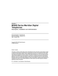
Avaya produce a very comprehensive
range of documentation for all of their
systems.
Previously they supplied an application
known as Helmsman which was used to
search the archive of documentation for
the relevant information.
However since Release 5, the
Helmsman
application
has
been
discontinued and Technical Publications
are delivered with an Adobe Acrobat
Index file which is used as the search
tool.
By opening the .PDX Index file you will
be offered the search dialogue seen
above. By selecting the option to search
in the Index file, all documents will be
referenced
and
all
occurrences
returned.
Notes
_____________________________________________________________
_____________________________________________________________
_____________________________________________________________
_____________________________________________________________
Copyright Amlex Associates Ltd
Page 4
CS 1000 Rel 7.5
16/04/2013
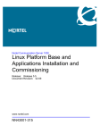
CS1000
The Call Server 1000 is Nortel’s
Heritage IP based PBX and can be
configured for up to 40,000 users. It is a
distributed architecture using standard
IP for all primary interconnections.
Meridian 1
The Meridian PBX is primarily a TDM
device with the option of adding IP
trunks or converting to full VoIP
operation.
Both devices share a lot of components
such as Cabinets and Chassis,
Intelligent Peripheral Interface (IPE)
cards, CPU’s and terminals.
The core of the operating system is
essentially the same across both
platforms with a few differences to
accomodate for the differing hardware.
Notes
_____________________________________________________________
_____________________________________________________________
_____________________________________________________________
_____________________________________________________________
Copyright Amlex Associates Ltd
5
CS 1000 Rel 7.5
16/04/2013
The Meridian comes in two distinct
types, the Large Switch Dual Processor
(Option 8100 & 6100) and the Small
Switch Single Processor (Option 11).
The primary differences are the actual
CPU board and physical layout.
Option 11 Small Switch
Uses a Small System Controller and is
housed in the Cabinet or Chassis. It can
comprise of multiple cabinets or chassis
which are inter connected.
A Small switch only uses Card and Unit
numbers to define a TN and these are
linked to the cabinet slot.
Option 8100 & 6100 Large Switch
At release 5 only the Pentium ii & iv may
be used as the CPU. As large switches
they use Loop Shelf Card and Unit to
define each TN. The system is consists
of Columns of Shelves.
On a large multi group system Shelves
are interconnected using Fibre Loop
(previously Junctor Board).
Copyright Amlex Associates Ltd
Notes
_____________________________________________________________
_____________________________________________________________
_____________________________________________________________
_____________________________________________________________
6
CS 1000 Rel 7.5
16/04/2013
The CS1000 is always a “Large Switch”,
in other words it always expects TN’s
(Terminal Number – internal address) to
be in the form of Loop, Shelf, Card, Unit.
The internal connections of the system
(ELAN – Embedded LAN) between
different components such as the Call
Server, Media Gateways and Signalling
Servers is established using IP and
Ethernet only. In this way a CS1000 can
be deployed in a distributed fashion
across a network.
Media Gateway – Houses the Cards for
the system, essentially the TDM
resources. Controlled by the Media
Gateway Controller. It also contains the
Media Cards/DSP boards which allow
the conversion between the two
environments. A media Card channel is
required for every IP to TDM call in
progress.
Signalling Server – acts as the
intermediary between the Call server
and the IP sets. In addition it provides
the signalling required to set up Virtual
Trunk Calls.
Copyright Amlex Associates Ltd
Notes
_____________________________________________________________
_____________________________________________________________
_____________________________________________________________
_____________________________________________________________
7
CS 1000 Rel 7.5
16/04/2013
The internal addressing of the system is
done using Terminal Numbers.
Actual TN’s are defined by the number
of Loops a system has and its
configuration.
On all release 5 and later CS1000E
systems this will be 256 loops (0-255),
however on Meridian systems this may
be smaller.
TN’s are used to address cards & units
on the cards. A normal TN can be
traced to a physical port on the system
itself.
Virtual TN’s on the other hand are used
to address devices where there is no
discrete physical connection port such
as IP telephones and Virtual Trunks.
This does mean that some correlation
needs to be made between the Virtual
TN of an IP Set and its IP address. This
is done by the Terminal Proxy Server
(TPS discussed later) on the Signalling
server at set registration time.
Notes
_____________________________________________________________
_____________________________________________________________
_____________________________________________________________
_____________________________________________________________
Copyright Amlex Associates Ltd
8
CS 1000 Rel 7.5
16/04/2013
Loops
The system has 256 loops which are
used to define the individual addresses
of devices. Loops are still used for
certain devices to address them rather
than a TN notably PRI loops and Tone
& Conference Loops.
Superloops
As the original system grew the concept
of a Superloop emerged which was
created by combining 4 Loops. Once
combined the contributing Loops would
be unavailable.
We can use different types of Superloop
but two which are essential for the
CS1000 are the IPMG Superloop and
the Virtual Superloop.
IPMG Superloop – Links the IP address
of the Media Gateway Controller to a
Superloop. Each Media Gateway
consumes half a Superloop i.e. Shelf 0
or 1.
Virtual Superloop – Is used for devices
which have no specific physical port
such as IP sets and Virtual Trunks.
Copyright Amlex Associates Ltd
Notes
_____________________________________________________________
_____________________________________________________________
_____________________________________________________________
_____________________________________________________________
9
CS 1000 Rel 7.5
16/04/2013
The ELAN (Embedded LAN) is a private
management network whilst the TLAN
(Telephony LAN) is connected to the
“Public” side. Telephones maybe
connected to the TLAN directly or to a
network routed from the TLAN
(Sometimes referred to as the CLAN
Customer LAN).
IP Sets need to communicate with the
Call Server to make and receive calls
and this is done by registering with the
Signalling server.
The Signalling server runs several
pieces of software but the sets use the
TPS, Terminal Proxy Server to register
with and to communicate with the call
server. The TPS records the IP address
of the Set and its Virtual TN so the Call
Server can contact it via the VTN.
For an IP to IP call the set will contact
the Call Server via the TPS. The Call
server will look up the VTN of the
destination set and refer it back to the
TPS which will contact the set.
When the call is established the voice
travels directly from IP Set to IP Set and
NOT via the sig server or call server.
Copyright Amlex Associates Ltd
Notes
_____________________________________________________________
_____________________________________________________________
_____________________________________________________________
_____________________________________________________________
10
CS 1000 Rel 7.5
16/04/2013
If the end point is a TDM set the call
server messages the Media Gateway to
allocate TDM/IP resource as well as
signalling the traditional set. The Voice
path for the completed call would be via
a Media Card as shown.
IP IP
IP Set to TPS with Dialled no.
TPS passes to Call Server
Call Server looks up Dialled No.
Call Server returns VTN to TPS
TPS signals Destination IP set
Codecs agreed
Zone Bandwidth Allocated
Destination picks up
Voice path established directly IP-IP
IP TDM
IP Set to TPS with Dialled no.
TPS passes to Call Server
Call Server looks up Dialled No.
Call Server contacts Media Gateway
with TN of set
Media Gateway signals destination &
allocates DSP (Media Card) resource
Codecs agreed
Zone Bandwidth Allocated
Destination picks up
Voice path established directly IP-DSP
DSP-TDM resource
Copyright Amlex Associates Ltd
Notes
_____________________________________________________________
_____________________________________________________________
_____________________________________________________________
_____________________________________________________________
11
CS 1000 Rel 7.5
16/04/2013
Virtual Trunks are used to carry VoIP
calls between systems without the need
for conventional circuits just using IP
networks.
This diagram shows the basic flow for a
Virtual Trunk IP to IP call. Set 1000 is
calling set 2000.
Set 1000 signals the call server via TPS
on the Sig Server
Call server identifies 2000 as a remote
set and sends the call to the Virtual
trunk gateway (SIP or H.323) on Sig
Server.
Sig server sends request to the NRS
(Network Routing Service) to identify
where 2000 is. (In Aura networks this
would be the Session manager)
NRS responds with the IP address of
the destination Signalling gateway.
The Signalling gateway on the initiating
system then contacts the Signalling
gateway on the destination system.
Request is sent to the CS on destination
as an inbound D-Channel.
CS looks up set 2000 and then sends a
call setup to it via the TPS on its
Signalling server.
Copyright Amlex Associates Ltd
Notes
_____________________________________________________________
_____________________________________________________________
_____________________________________________________________
_____________________________________________________________
12
CS 1000 Rel 7.5
16/04/2013
Unified Communications Manager
The UCM framework adds a complete
management and Security Domain to
the CS1K environment defined by the
Primary UCM which can be a CS1K
Linux server or Aura System Manager.
It controls access to the systems and
servers
as
well
as
regulating
communications between them.
When the component devices are
initially configured ( Call Server, Media
Gateway etc) they are outside of the
UCM domain but can communicate at a
basic level. For full functionality however
they must be added to the UCM domain.
This is done in one of two ways
LD 117 REG UCM SYS
Or on the command line of the device
e.g. MGC card
oam> joinSecDomain
These
commands
complete
the
registration of the devices to allow SSH
communications
between
them.
Specifically IP Node synchronisation
and MGC configuration download.
Copyright Amlex Associates Ltd
Notes
_____________________________________________________________
_____________________________________________________________
_____________________________________________________________
_____________________________________________________________
13
CS 1000 Rel 7.5
Once the UCM security Domain is
established the Primary UCM server
controls
all
communications
and
authorisation.
If a user tries to login to a signalling
server or call server as shown in the
diagram, their login credentials will be
passed to the Primary UCM for
validation and Authorisation.
In this way a call server created with a
new default database will have the
users “admin2” & “admin1” available.
However once the Call server has been
registered within the security domain it
will only have the user “admin” available
for login until further UCM users are
created.
In essence the Primary UCM runs a
RADIUS server which is used for the
Authorisations. In the event that a failure
occurs and the Primary UCM cannot be
reached in a CS1K implementation the
Backup server will be contacted for
authorisation as it has a copy of the
database. If the Backup is unavailable
then an “Emergency” account is used to
login to the server.
The Aura System manager has its own
redundancy scheme.
Copyright Amlex Associates Ltd
Notes
_____________________________________________________________
_____________________________________________________________
_____________________________________________________________
_____________________________________________________________
14
CS 1000 Rel 7.5
Devices that have become part of the
UCM domain are added automatically to
the Elements list shown here.
This can be used to access the different
servers and the services running on
them such as the Base Linux, NRS or
the Element Manager
Note the Media Gateway has been
added to the Elements list but is not a
link (i.e. Not underlined ). Thus it cannot
be clicked on to gain access to the
device. This is the same with VxWorks
based Call Servers.
No further login is required to access the
elements, this is known as Single Sign
On or SSO.
Notes
_____________________________________________________________
_____________________________________________________________
_____________________________________________________________
_____________________________________________________________
Copyright Amlex Associates Ltd
15
CS 1000 Rel 7.5
16/04/2013
System Manager is the management
interface for the Avaya Aura system
integration suite of communications
programmes .
When CS1K is implemented through
Aura this will be the Primary UCM
element and the login screen for
management. Thus it will deal with the
Authentication,
Authorisation
and
Accounting for the system as well as the
Certificates for the different Elements.
The Highlighted menu options are the
primary elements used for managing a
CS1K implementation via System
Manager.
Notes
_____________________________________________________________
_____________________________________________________________
_____________________________________________________________
_____________________________________________________________
Copyright Amlex Associates Ltd
16
CS 1000 Rel 7.5
16/04/2013
The Aura Session Manager is the SIP
Proxy core of the Aura architecture and
plays a key role in orchestrating
communications
between
different
elements of the system.
Its role is equivalent to that of the
Network
Routing
Service
(NRS)
excepting that it does not deal with
H.323 call routing. For the CS1K it
effectively replaces the SIP Proxy or
Redirect server and the Network
Connect Server (NCS) elements of the
NRS.
Session manager always works as a full
SIP proxy and has mechanisms to
monitor the connection to the SIP
entities it is managing as can be seen
here. This is the reverse of the situation
for endpoints on the NRS which
constantly Re-register ensuring the
system knows they are still available for
call processing.
Notes
_____________________________________________________________
_____________________________________________________________
_____________________________________________________________
_____________________________________________________________
Copyright Amlex Associates Ltd
17
CS 1000 Rel 7.5
16/04/2013
The Node ID is a number of up to 4
digits used to identify the Telephony
node. The Node IP Address is a TLAN
address but not the TLAN address of
the sig server itself and represents the
whole node.
The Node IP Address is held by the
Leader signalling server of the IP
telephony node.
Devices in the Node are either a Leader
(one only) or Follower. In the event of a
failure of the Leader the Followers will
elect a new Leader which will then
assume the Node IP address as well as
its own TLAN address.
The IP sets are configured to connect to
the IP Node address for registration,
thus even in the event of a Sig server
failure the IP Node address will still be
available via the new Leader.
All of the devices running TPS are
included in the IP Telephony node.
A system can have multiple IP Nodes if
required.
Copyright Amlex Associates Ltd
Notes
_____________________________________________________________
_____________________________________________________________
_____________________________________________________________
_____________________________________________________________
18
CS 1000 Rel 7.5
16/04/2013
Notes
_____________________________________________________________
_____________________________________________________________
_____________________________________________________________
_____________________________________________________________
Copyright Amlex Associates Ltd
19
CS 1000 Rel 7.5
16/04/2013
Release 6 introduced the CoRes Call
server with both the Call server and
Signalling server resident on the same
CPPM card running Linux. This is
achieved using a VxWorks emulator
(VxEll). Release 7 enhances this with
new hardware.
The Standard Availability call server can
support up to 40,000 users and has a
single CPPM card running VxWorks.
The High Availability call server adds a
second redundant CPU to enable
failover as well as well as reducing
downtime for system upgrades.
HA is sometimes referred to as Campus
Redundancy when the CPU’s are
housed in different locations. The
maximum distance is defined by the
speed of the High Speed Pipe link which
ensures the memory and FMD (Fixed
Media
Device)
are
constantly
synchronised.
HS is a Rel 7 feature allowing the
“Clustering” of HA systems for even
greater user numbers.
Copyright Amlex Associates Ltd
Notes
_____________________________________________________________
_____________________________________________________________
_____________________________________________________________
_____________________________________________________________
20
CS 1000 Rel 7.5
16/04/2013
High Scalability provides a new platform
for very large systems. It combines up to
6 High Availability systems, one the
Primary and the rest as Members.
A new Element Manager HS is used to
provide configuration of common
elements across the systems.
Inter-Nodal traffic is transported using
SIP and an Internal dial plan established
for this. Common areas of the database
are “Shared” from the Primary to
“Member” call servers using a
Specialised HS Element Manager.
Notes
_____________________________________________________________
_____________________________________________________________
_____________________________________________________________
_____________________________________________________________
Copyright Amlex Associates Ltd
21
CS 1000 Rel 7.5
16/04/2013
Pentium IV processors are housed in
their own chassis (Two shown in the
picture ).
The chassis has three slots however the
top slot is not used ( used for Drive
carrier card for Pentium II systems). The
Middle slot carries the CPU card itself
whilst the lower slot has the Utility card.
The Utility card has the DIP switches
used to tell the system which processor
is CP0 and which CP1. It also carries
the system security Dongle.
Notes
_____________________________________________________________
_____________________________________________________________
_____________________________________________________________
_____________________________________________________________
Copyright Amlex Associates Ltd
22
CS 1000 Rel 7.5
16/04/2013
Common Platform Pentium Mobile
(CPPM) call servers are a single board
solution and can be used for Standard
availability (SA) & High availability (HA)
systems. The security device is carried
on the board itself and the “Side “
information is set in the bios of the
board.
As a call server, the CPPM has a 1GB
Compact flash as its FMD (fixed Media
Device – hard drive) and uses a 512 Mb
compact flash for software installation,
RMD (Removable Media Device). To set
the board to boot from the compact flash
the onboard switch is set to position 1.
CPPM devices use a standard IPE slot
in a Media Gateway but only receive
power from it and connect to the
console port through it. They do not
communicate with other cards in the
chassis
or
cabinet
across
the
backplane.
A High Availability CPPM based system
will support a combination of up to 50
Media gateways or 40000 IP Sets.
Copyright Amlex Associates Ltd
Notes
_____________________________________________________________
_____________________________________________________________
_____________________________________________________________
_____________________________________________________________
23
CS 1000 Rel 7.5
16/04/2013
Common Platform Pentium Mobile (CPPM)
Linux server can be used as a Signalling
Server or Co-resident Call server or merely
a Primary or Backup UCM.
The CPPM Linux server is the same board
as the call server but it is now equipped with
at least a 40Gb laptop hard drive instead of
the 1Gb compact flash, 2Gb or RAM and the
onboard switch is set to position 2 to ensure
it boots from the hard disk.
CPPM devices use a standard IPE slot in a
Media Gateway but only receive power from
it and connect to the console port through it.
They do not communicate with other cards
in the chassis or cabinet across the
backplane. If you are using a CPPM sig
server in a 1000M it must be the dual width
device to avoid fouling other cards.
Single width CPPM for use in Media
gateways :NTDW61
Dual width CPPM for use in CS1000M :NTDW66
Single width Metal faceplate CPPM for use
in Media gateways 1010 :NTDW99
Copyright Amlex Associates Ltd
Notes
_____________________________________________________________
_____________________________________________________________
_____________________________________________________________
_____________________________________________________________
24
CS 1000 Rel 7.5
16/04/2013
The CPMG card combines the
functionality of both Linux Server and
Media Gateway Controller.
This gives a single slot option for a
CoRes Call server for small systems.
The card is available with either 32 or
128 DSP’s which are fixed on the board
and therefore not upgradeable.
Linux Server is accessed using the TTY
ports on the front of the card presented
as RJ45 sockets. A special adaptor
(RJ45 to 9 pin D type) is required to
connect to the serial port .
The Media Gateway component is
configured as an MGS to the call server.
It uses the existing TTY connection via
the chassis SDI port thus configuration
is completely separate from Linux sever.
The Call server and Media Gateway can
have
separate
internal
Ethernet
connections and IP addresses but the
CPMG has an internal Ethernet switch
so connection is automatically achieved
between the two devices once the IP
addresses are configured.
Copyright Amlex Associates Ltd
Notes
_____________________________________________________________
_____________________________________________________________
_____________________________________________________________
_____________________________________________________________
25
CS 1000 Rel 7.5
16/04/2013
The CPDC card replaces the CPPM
card for Linux applications. The CPPM
will no longer be supplied new for Linux
CoRes
deployments
(Upgrades
allowed) .
The CPDC will not support VxWorks so
is not available for the SA or HA
configurations.
The server has no INI or DIP switches
for configuration but does have a VGA
port on the front of the card.
The card shares the same TTY port
cable as the CPPM card.
The CPDC can support the new IP
Media Application Services or MAS
server. This is a method of providing IP
based
conferencing
tones
and
announcements.
Notes
_____________________________________________________________
_____________________________________________________________
_____________________________________________________________
_____________________________________________________________
Copyright Amlex Associates Ltd
26
CS 1000 Rel 7.5
16/04/2013
HP, IBM & Dell servers are known as
COTS (Commercial of the Shelf )
servers. They come with 2 Gb of
memory and either one or two hard
drives. They have at least 2 Ethernet
ports for ELAN & TLAN and run Linux.
The COTS1 servers, HP DL320 and
IBM x306 only have a single 80Gb drive
as standard and were originally
introduced with CS1k Release 5.
The COTS2 servers, Dell R300 and IBM
3350 were introduced with CS1K
Release 6 and feature redundancy of
Hard disk and power supplies. This
makes them an excellent choice as a
platform for the Primary UCM.
NOTE:The ISP1100 is not supported for Linux
and thus cannot be used after Release
5.
Notes
_____________________________________________________________
_____________________________________________________________
_____________________________________________________________
_____________________________________________________________
Copyright Amlex Associates Ltd
27
CS 1000 Rel 7.5
16/04/2013
Either the Chassis or Cabinet can be
used for the Media gateway on a
CS1000E system.
The Chassis is a 5 slot main unit with an
optional 4 slot Expander cabinet. The
two are connected using 2 copper
cables.
The expander is a part of the main
media gateway and only adds the 4 card
slots , no other functionality.
Notes
_____________________________________________________________
_____________________________________________________________
_____________________________________________________________
_____________________________________________________________
Copyright Amlex Associates Ltd
28
CS 1000 Rel 7.5
16/04/2013
If using the Media Gateway chassis then
the picture shows the relevant ports for
connection. The cards in the units will
use the 25 Pair connectors to link to the
MDF. In a chassis configuration the
Main unit & Expander are linked by 2
copper cables.
MGC SDI (Serial Data Interface) ports
are connected using the “Triple Cable”
these ports are used for the initial
configuration of the MGC card itself but
once it has been integrated and has
registered with the call server they can
be configured as further TTY ports on
the call server itself for access or CDR
collection etc.
The ELAN & TLAN ports on the back of
the chassis are the redundant
connections for the MGC and mirror the
1E & 2T ports on the faceplate of the
card itself. If you are not using multi
homing then either connection maybe
used. Swapping between these ports is
controlled by the MGC itself and is not
reliant upon any other network
interaction.
Copyright Amlex Associates Ltd
Notes
_____________________________________________________________
_____________________________________________________________
_____________________________________________________________
_____________________________________________________________
29
CS 1000 Rel 7.5
16/04/2013
The Bulkhead ports on the Media
Gateway are used purely for connecting
to the back of the chassis. They act like
an extension cable only and can be
used by any connection ELAN or TLAN
on the system.
The DIP switches are used to set the
ring frequency etc and should be set
according to the relevant NTP country
information.
Notes
_____________________________________________________________
_____________________________________________________________
_____________________________________________________________
_____________________________________________________________
Copyright Amlex Associates Ltd
30
CS 1000 Rel 7.5
16/04/2013
The Media Gateway cabinet is similar in
requirements to the chassis as far a
card connections go but he location of
connectors is at the bottom of the
cabinet as shown here.
The SDI ports are connected again
using the triple cable, and the ELAN &
TLAN redundant ports are connected
using a specialised adaptor similar but
not the same as the Media card adaptor.
This allows for the duplication of the 1E
& 2T ports on the faceplate of the MGC
itself in slot 0.
Notes
_____________________________________________________________
_____________________________________________________________
_____________________________________________________________
_____________________________________________________________
Copyright Amlex Associates Ltd
31
CS 1000 Rel 7.5
16/04/2013
The Media Gateway 1010 is a rack
mounted chassis which has provision for
up to 10 IPE cards. In addition it can
house two CPPM cards in dedicated
slots thus not using up IPE slots.
The chassis uses a standard MGC card
but has an additional MGU (Media
Gateway Utility card ) which allows
access to the console ports of the MGC
and CPPM cards installed as well as
supporting the redundant ELAN and
TLAN ports of the MGC.
In addition to increase resilience of the
chassis it has a redundant power supply
and triple fan units. This addresses one
of the primary concerns over the
standard 5 slot Media Gateway chassis.
Notes
_____________________________________________________________
_____________________________________________________________
_____________________________________________________________
_____________________________________________________________
Copyright Amlex Associates Ltd
32
CS 1000 Rel 7.5
16/04/2013
Uses slot 0 in Media Gateway and Is
keyed so it wont fit in any other slot.
The MGC uses a Gold Image to boot
from and connect to the call server, thus
no software has to be installed on the
card. Updates are downloaded from CS
and stored on the 128Mb Compact
flash.
The MGC has 3 SDI ports on the board
which are presented on the triple cable
from the port on the cabinet or chassis.
The first port is used to configure the
card initially but after that they can be
configured as extra TTY ports for the
call server.
The MGC has space for 2 DSP
daughter boards which come as either
32, 96 or 128 port boards.
The 4 digit display on the front of the
card displays the LOOP & SHELF when
it is connected to a call server.
At boot up it reports its self test BOOT,
POST (Power on self test), PASS (Pass
self test), LOAD (Application Loading).
In the event of an error it will display
Exxx where xxx is the error number.
Copyright Amlex Associates Ltd
Notes
_____________________________________________________________
_____________________________________________________________
_____________________________________________________________
_____________________________________________________________
33
CS 1000 Rel 7.5
16/04/2013
The addition of the 128 port DSP card
increases the number of TDM/IP calls
that can be supported using on the
MGC card slot. From Rel 5 when the
MGC was first introduced it was
available with both a 32 and 96 port
DSP card and the card could e
configured with both a 32 and 96 port
card to achieve 128 ports in total.
This can now be extended to 160 ports
by using a 128 and 32 port card.
In the PRI gateway two DSP 96 or DB
128 cards can be used to create a non
blocking environment.
In this configuration the system must
have the Package 418 enabled to
function correctly.
DTR’s can now also be created on card
0 to allow for the use of the DB 128
card.
Copyright Amlex Associates Ltd
Notes
_____________________________________________________________
_____________________________________________________________
_____________________________________________________________
_____________________________________________________________
34
CS 1000 Rel 7.5
16/04/2013
The LAN connections for the system are
important and in order to maximise the
redundancy of the switch you can take
advantage of the multi homing aspects
of the MGC cards.
The diagram above shows 3 media
gateways schematically and their MGC
cards. These are connected to
redundant ELAN & TLAN Ethernet
switches via the front faceplate and
“rear” redundant ports. This allows the
MGC to continue to function even if one
of the ELAN or TLAN switches fails.
NB Note that the interconnection
between the Ethernet switches has
been omitted for clarity.
To fully utilise this redundancy the Call
Server ELAN connections have been
connected to the network using the pass
through ports ( CE ) on the front of the
MGC. Similarly the Sig Server has both
ELAN & TLAN connections to CE & CT
on the front of its MGC card.
Copyright Amlex Associates Ltd
Notes
_____________________________________________________________
_____________________________________________________________
_____________________________________________________________
_____________________________________________________________
35
CS 1000 Rel 7.5
16/04/2013
The Media Card 32 S provides TDM to
IP conversion as did its predecessor the
VGMC (Voice Gateway Media Card) .
However
it
has
the
additional
functionality to encrypt the voice media
using Secure Real Time Protocol
(SRTP).
This card can be used where there is no
opportunity to use the DSP daughter
boards of a MGC in a CS1000M
configuration where there are no Media
Gateways at all.
It is configured as a part of the IP
telephony node but no longer runs TPS
as it did in Release 5.
The ELAN & TLAN connections for the
card are achieved using a specialised
adaptor which plugs into the 25 pair
connector for the card. The Ethernet
port on the faceplate is currently
unused.
Notes
_____________________________________________________________
_____________________________________________________________
_____________________________________________________________
_____________________________________________________________
Copyright Amlex Associates Ltd
36
CS 1000 Rel 7.5
16/04/2013
The dedicated PRI gateway is a 19”rack
chassis with two cards installed. A
single Media Gateway controller and an
8 span PRI card. The Quad PRI card is
expanded to from 4 to8 circuits using an
add on daughter board.
The system is initially programmed via a
serial
connection
to
assign
IP
addressing and subsequently through its
own Web interface.
To prevent blocking the MGC card can
have two 96 port or 128 port DSP
boards installed on it (Requires package
418).
Notes
_____________________________________________________________
_____________________________________________________________
_____________________________________________________________
_____________________________________________________________
Copyright Amlex Associates Ltd
37
CS 1000 Rel 7.5
16/04/2013
The MG XPEC is a new controller that
allows an existing IPE shelf from a
Single or Multi group switch to be reused in a CS1000E environment.
The card is effectively a Dual MGC and
replaces the shelf controller creating a
Dual MGC which can be integrated
within a CS1000 architecture.
Notes
_____________________________________________________________
_____________________________________________________________
_____________________________________________________________
_____________________________________________________________
Copyright Amlex Associates Ltd
38
CS 1000 Rel 7.5
16/04/2013
For high numbers (> 1000) of Users on
a CS1K system the Call server options
are a VxWorks based Standard
Availability or High Availability system .
(High Scalability systems are based on
multiple HA configurations).
The VxWorks installation must be
carried out directly to the server itself, no
deployment options are available from
the UCM. The server will of course
require a UCM, Signalling Server and
Element Manager which are provided by
the CPMG card in the example shown
(not a typical configuration).
As the VxWorks Call Server has initially
no relationship to the Linux server,
unlike a CoResident option, it must have
its IP addressing added after installation
and be assigned to the SS & EM during
their deployment.
As the CPMG is not acting as a Call
Server in this instance it will not require
a Dongle for installation.
Copyright Amlex Associates Ltd
Notes
_____________________________________________________________
_____________________________________________________________
_____________________________________________________________
_____________________________________________________________
39
CS 1000 Rel 7.5
16/04/2013
The installation of the VxWorks Call
Server is still carried out using a
specially prepared Compact Flash (CF)
card inserted in the RMD (Removeable
Meia Device) slot on the front of the
card.
As the system boots strike the F key
when prompted to boot from the
Faceplate CF and if the system has
been used before (i.e. There are system
files on the FMD (Fixed Media Device)
type F again when prompted to select
the CF boot.
Proceed with the installation typing Y to
the first two questions until you are
offered the INSTALL MENU selection.
The Next prompt will be to identify the
Keycode from a list select the
appropriate item (HA for our purposes).
The system then checks this is a valid
option and asks for confirmation.
Notes
_____________________________________________________________
_____________________________________________________________
_____________________________________________________________
_____________________________________________________________
Copyright Amlex Associates Ltd
40
CS 1000 Rel 7.5
16/04/2013
The INSTALL MENU will then be
displayed and the appropriate selection
made. We are using option B to install
the Software, Bootrom and a Database.
The system will then check the SIDE
setting of the call server. For an HA
(High
Availability)
system
the
processors need to be defined as 0 or 1
i.e. They must be unique to allow the
duplication
of
their
running
configurations. On the CPPM card this
is held in the BIOS and is set during
install.
For an SA (Standard Availability) system
set the side to 0.
Notes
_____________________________________________________________
_____________________________________________________________
_____________________________________________________________
_____________________________________________________________
Copyright Amlex Associates Ltd
41
CS 1000 Rel 7.5
16/04/2013
As the CPPM is installed in a Media
Gateway card slot it will then ask which
one. This information is only used by the
inventory command in LD 117 and does
not affect the system performance if set
incorrectly.
See overlay 117
> CHG LCL Loop Shelf
Add the LOOP and SHELF designation
for the Media Gateway that the card is
installed in. The Slot number will be
picked up automatically.
Notes
_____________________________________________________________
_____________________________________________________________
_____________________________________________________________
_____________________________________________________________
Copyright Amlex Associates Ltd
42
CS 1000 Rel 7.5
16/04/2013
The system is now ready to install and
prompts to check the release of software
to be installed. This is the software on
the Compact Flash installer itself hence
the reference to RMD.
Notes
_____________________________________________________________
_____________________________________________________________
_____________________________________________________________
_____________________________________________________________
Copyright Amlex Associates Ltd
43
CS 1000 Rel 7.5
16/04/2013
The installer will now prompt to check if
Centralised Software Upgrade should
be used. This is the mechanism that
allows Media Gateways to download
Loadware upgrades automatically and
should be enabled.
The second question is whether this
should be done Sequentially or
Simultaneously i.e. One at a time or all
together.
Notes
_____________________________________________________________
_____________________________________________________________
_____________________________________________________________
_____________________________________________________________
Copyright Amlex Associates Ltd
44
CS 1000 Rel 7.5
16/04/2013
One of the last question requests the
Languages to be supported by the
system. You are then presented with a
summary and asked if the installation
should proceed.
Notes
_____________________________________________________________
_____________________________________________________________
_____________________________________________________________
_____________________________________________________________
Copyright Amlex Associates Ltd
45
CS 1000 Rel 7.5
16/04/2013
Once the software has been installed
the system will return a prompt to
continue and request the database to be
installed.
On the database selection Menu we
have chosen option b the Default
Database although an existing database
could be used or a small system
database converted (Option d). Once
selected
the
system
asks
for
confirmation and then proceeds.
Once this is complete the system
returns to the main menu where you
should select the Quit option using the
prompts on the screen to Quit the
installer and Reboot the machine rather
than using the Reset button on the card
itself.
When configuring a HA system you will
repeat the install on the second Call
Server ensuring the High Speed Pipe is
connected between the two when they
reboot. This should allow them to JOIN
together with one becoming the ACTIVE
call server while the other runs in
STANDBY mode.
Once the system boots you will be able
to login using the CS1K account
“admin2 with the password “0000”.
NOTE: The STANDBY CS will not allow
a login when joined to the ACTIVE CS.
The overlays will only be available on
the standby when the systems are
SPLIT (LD 135), this is to allow upgrade
etc.”
Copyright Amlex Associates Ltd
Notes
_____________________________________________________________
_____________________________________________________________
_____________________________________________________________
_____________________________________________________________
46
CS 1000 Rel 7.5
16/04/2013
The call server is configured through
both the command line interface (CLI)
as well as the Element Manager (EM).
The command line is based on
“Overlays” or “Loads” and to interact
with the system you need to be in the
correct “Load” (LD) or “Overlay”.
To login type “LOGI” (Not case
sensitive) at the prompt, and either add
the username you wish to use on the
same line or hit enter for the USERID
prompt. Once the Username is input the
system will then request a password.
Once logged in to the CLI you change
“Overlays” by typing LD and the number
of the overlay you require. You must exit
an overlay before you can enter another
and this is done by typing ****.
There are a few lesser known
commands that can be very helpful
shown on the right. These allow you to
use a limited set of online help and to
look up error codes that appear without
exiting the overlay.
LON & LOF allow you to backspace in
the command line !!
Copyright Amlex Associates Ltd
Notes
_____________________________________________________________
_____________________________________________________________
_____________________________________________________________
_____________________________________________________________
47
CS 1000 Rel 7.5
16/04/2013
The overlay structure is organised as
shown into three primary areas.
System
Which deals with the Configuration
records, such things as Superloops.
Customer
Most systems only have one customer
but there can be several. This deals with
the setup of specifics for a particular
customer e.g. Routes and Trunks and
CPND information.
Terminal or Set
Relates to the actual set properties.
Whilst it shows LD 10 & 11 which still
exist it is wise to remember that LD 20 is
now a linked overlay allowing operations
to be carried out for LD 10, LD 11 & LD
32.
Notes
_____________________________________________________________
_____________________________________________________________
_____________________________________________________________
_____________________________________________________________
Copyright Amlex Associates Ltd
48
CS 1000 Rel 7.5
16/04/2013
As we have a High Availability system
we need to check that the system is
synchronising correctly between the two
cores.
To check the status use the > STAT
CPU command in LD 135 . What we
should see is a REDUNDANT Status for
both the SYSTEM and DISK. This
means that both the memory and the
disk
(FMD)
have
successfully
synchronised allowing us to swap
service from one core to the other.
There is also a test which can be run
from LS 137
>TEST RDUN
Be patient as the test can take over a
minute to run.
To swap the Active and Standby Call
servers over we can use the command
in LD 135
> SCPU
Copyright Amlex Associates Ltd
Notes
_____________________________________________________________
_____________________________________________________________
_____________________________________________________________
_____________________________________________________________
49
CS 1000 Rel 7.5
16/04/2013
In order to upgrade a High Availability
system with a minimal loss of service we
first need to SPLIT the two cores so we
can login to the Standby side.
Once the SPLIT command has been
issued you will see the Standby system
initialise offering the overlays to login to.
(When the two cores are synchronised
the standby will be running background
tests and the overlays/login will not be
available although you can login with
PDT).
The ACTIVE core is still processing
calls for the system but will no longer try
to synchronise with the standby system.
At this point if we were carrying out an
upgrade we would now install the
upgrade to the Standby system and
check its validity before bringing it into
service.
Notes
_____________________________________________________________
_____________________________________________________________
_____________________________________________________________
_____________________________________________________________
Copyright Amlex Associates Ltd
50
CS 1000 Rel 7.5
16/04/2013
Whilst the command SCPU will swap
the call servers when they are joined
together when they are SPLIT as we
can see here we need to use a different
command
> CUTOVR
Issuing the command after upgrading
the standby system would bring the
upgraded software into service. The
cares would still be Split and thus we
could then upgrade the second core
before joining them back together.
Notes
_____________________________________________________________
_____________________________________________________________
_____________________________________________________________
_____________________________________________________________
Copyright Amlex Associates Ltd
51
CS 1000 Rel 7.5
16/04/2013
Finally to bring the two cores back
together we use the JOIN command
from LD 135.
The two CPU’s will synchronise and the
standby
core
will
resume
the
background test mode.
Finally we can use the STAT HEALTH
command to view the system health
which is a number based on the
different components of the system and
can be used as a gauge of problems
with the system.
Notes
_____________________________________________________________
_____________________________________________________________
_____________________________________________________________
_____________________________________________________________
Copyright Amlex Associates Ltd
52
CS 1000 Rel 7.5
16/04/2013
The debate rages as to which interface,
the CLI or the Element Manager is the
easiest to use for configuring and
administering the CS1000. In truth it is
probably down to how long you have
used the system, and the CLI does have
a speed advantage if you know exactly
what you want to do.
However one area that the Element
manager probably wins on is reviewing
configuration information as it is
presented in web page format with
some explanation.
If you want to review configuration
information through the CLI then the
slide here is a useful one to remember
as it points you to the relevant overlay
for printing data.
Notes
_____________________________________________________________
_____________________________________________________________
_____________________________________________________________
_____________________________________________________________
Copyright Amlex Associates Ltd
53
CS 1000 Rel 7.5
16/04/2013
One thing to always try when devices
seem to be okay but still function
incorrectly is to DISABLE them and then
ENABLE.
Depending on the device you are
working on you need to choose the right
command as shown here. For a single
phone you can use the unit option DISU
command in LD 20 (or LD 32). Be aware
that on a set the display will remain as if
the set is working however you wont be
able to pick up a line to dial with.
Whilst you can do this with a single
digital set it often better to disable the
whole card and then re-enable it. This
ensures that it re initialises with the Call
Server correctly. Use the DISC for this
option.
For replacement or maintenance tasks
all cards should be disabled before
removal.
Some devices such as PRI , Tone and
Conference circuits are addressed as
Loops. Thus you use the DISL
command to disable these in specific
overlays:PRI – 60 / TDS – 34 / CONF - 38
Copyright Amlex Associates Ltd
Notes
_____________________________________________________________
_____________________________________________________________
_____________________________________________________________
_____________________________________________________________
54
CS 1000 Rel 7.5
16/04/2013
The Element Manager commands in the
left hand menu are grouped together to
ease navigation.
In addition groups of commands are
Sub – Grouped and you will see a +
sign where there are more options
which have been hidden for clarity.
Here you can see the Main Header
SYSTEM with the Sub Group IP
NETWORK expanded to show the
options below it. The NODES,
SERVERS, MEDIA CARDS option had
been used to edit the IP Telephony
Node.
Note also the “Bread Crumb” trail at the
top of the display pane highlighted by
the Red arrow. This shows exactly
where you are in relation to the Menus
and
also
includes
Hyperlinks
(Underlined Items) which allow you to
move to a different screen without
starting back at the initial screen. Note
its is not good practice to use the BACK
button in the browser as it can lead to
display of information which isn’t
current.
Copyright Amlex Associates Ltd
Notes
_____________________________________________________________
_____________________________________________________________
_____________________________________________________________
_____________________________________________________________
55
CS 1000 Rel 7.5
16/04/2013
If we choose the default database option
on the installation we will need to
configure some settings on the call
server to ensure it can talk to the
Element Manager correctly and is ready
for system configuration.
Note that in a CoRes system the IP
information will be taken from the Linux
base so there is no need for IP
Configuration and the commands are
disabled in LD 117 for this.
Notes
_____________________________________________________________
_____________________________________________________________
_____________________________________________________________
_____________________________________________________________
Copyright Amlex Associates Ltd
56
CS 1000 Rel 7.5
16/04/2013
Here is an example login to the call
server overlays using the admin2
account.
It is good to use the admin2 account at
this point rather than the admin1 as it
has greater privileges and is the only
account which can perform security
operations which we will need when the
Call servers are added to the UCM.
Notes
_____________________________________________________________
_____________________________________________________________
_____________________________________________________________
_____________________________________________________________
Copyright Amlex Associates Ltd
57
CS 1000 Rel 7.5
16/04/2013
The Call Server needs to have an IP
address. This ELAN address is set on
the call server in load 117.
Dependent on the configuration either
one or two addresses may be required.
If the system is Standard Availability
(SA) then only one address is needed
but if it is High Availability (HA - Dual
CPU ) then an address is required for
both CPU’s
.
The process is to assign an IP address
to a Hostname using the
NEW
HOST
“Hostname”
“IP
Address”
command.
The Subnet Mask can be set using the
command
CHG MASK “Subnet Mask”
Once this is done the Address is
brought into service by command
CHG ELNK ACTIVE (or INACTIVE)
“Hostname”
A Default Route is added using the
commands
=>NEW ROUTE 0.0.0.0 “IP Addr of
Router”
=>PRT ROUTE
=>ENL ROUTE “Route ID from list”
In LD 137 there are commands to
enable & Disable the ELAN as well as
seeing its status
ENL ELNK / DIS ELNK / STAT ELNK
Copyright Amlex Associates Ltd
Notes
_____________________________________________________________
_____________________________________________________________
_____________________________________________________________
_____________________________________________________________
58
CS 1000 Rel 7.5
16/04/2013
Pseudo TTY ports are used for
networked access to the call server. A
TTY port is usually associated with a
physical serial port whereas PTY’s are
not.
PTY’s are used by the Element
Manager and SSH connection to the call
server so are essential. The default
database has at least one PTY which
was there originally to support
Telephony Manager. Ensure there are
sufficient PTY’s to support access.
Notes
_____________________________________________________________
_____________________________________________________________
_____________________________________________________________
_____________________________________________________________
Copyright Amlex Associates Ltd
59
CS 1000 Rel 7.5
16/04/2013
Because of the use of the default
database in our example we have XCT
conference circuits provisioned on loops
0 and 16.
The dialogue shows their removal using
overlay 17.
Notes
_____________________________________________________________
_____________________________________________________________
_____________________________________________________________
_____________________________________________________________
Copyright Amlex Associates Ltd
60
CS 1000 Rel 7.5
16/04/2013
MultiUser allows for more than one
connection to be made by a user and is
necessary for Element Manager to run
correctly.
In addition it allows the use of the !ERR
option to check error codes without
moving out of an overlay.
Notes
_____________________________________________________________
_____________________________________________________________
_____________________________________________________________
_____________________________________________________________
Copyright Amlex Associates Ltd
61
CS 1000 Rel 7.5
16/04/2013
Adding a new customer in LD 15. The
Customer is a way of grouping things
together when you share a call server.
We must have at least one customer
and this will be Customer 0. Without it
the system cannot group together the
different configuration tables and
commands will fail.
Notes
_____________________________________________________________
_____________________________________________________________
_____________________________________________________________
_____________________________________________________________
Copyright Amlex Associates Ltd
62
CS 1000 Rel 7.5
16/04/2013
The Digital Data Block is created so we
have a default PAD table which is
needed for the Voice Gateway Channels
(VGW) used to enable the IP to TDM
translation via the DSP & Media cards.
The Digital Data Black is also used
when we configure some trunk settings.
These default “Tables” within the
database have to be there as the enable
the system to link things together as well
as setting default values. The configured
values may not even be used in our
configuration but if the table cant be
referenced the system will report a
problem.
Notes
_____________________________________________________________
_____________________________________________________________
_____________________________________________________________
_____________________________________________________________
Copyright Amlex Associates Ltd
63
CS 1000 Rel 7.5
16/04/2013
A Bandwidth Zone is required for
configuration of both the IP Phones and
the IP Media Gateways.
The simplest way to add a Zone at this
point is to create it in LD 117. Using the
command “new zone 1”creates a
Bandwidth Zone 1 with the default
values.
As shown you can allocate actual
Bandwidth figures and Strategy but this
is much easier done in the Element
Manager later on.
Note the PRT INTRA command which
prints the zones configured on the
system and the values associated. You
can see here that Zone 10 is a Virtual
Trunk zone thus not available for IP sets
.
Notes
_____________________________________________________________
_____________________________________________________________
_____________________________________________________________
_____________________________________________________________
Copyright Amlex Associates Ltd
64
CS 1000 Rel 7.5
16/04/2013
A Virtual Superloop can be configured in
LD 97 or the Element Manager. The
example shows configuring
a
Superloop 252 as a Virtual Superloop.
Virtual Superloops are required to
support the IP sets and Virtual Trunks
which will be configured on the system.
In reality you may need several Virtual
Superloops to support the configuration
you require.
Notes
_____________________________________________________________
_____________________________________________________________
_____________________________________________________________
_____________________________________________________________
Copyright Amlex Associates Ltd
65
CS 1000 Rel 7.5
16/04/2013
The installation of the Linux servers is a
three stage process where the Linux
Base is installed first. This contains the
Common Services which Avaya have
added into the Linux core to support the
Call Server, Signalling Server, NRS and
other processes.
The Base Linux installation also covers
the configuration of IP address
information as well as the time zone and
the Passwords for the two Linux
accounts “root” and “admin2”.
Once the Linux Base is installed the
initial Security Configuration is done to
select the server role, generate the
default certificate and add the “admin”
user password.
Once this is completed the deployment
of applications maybe commenced.
Notes
_____________________________________________________________
_____________________________________________________________
_____________________________________________________________
_____________________________________________________________
Copyright Amlex Associates Ltd
66
CS 1000 Rel 7.5
16/04/2013
The minimum configuration for any
Linux server is 2Gb or RAM and a 40Gb
Hard disk drive.
Where a CCPM card is being
redeployed from an existing release 5
System it will need a RAM upgrade.
This is done by adding a second 1Gb
memory card into the spare slot. In
addition it may need a Hard drive added
which needs to be at lease 40Gb
capacity but can be larger.
In addition where the CPPM card has
been used on a Rel 5 system you will
need to ensure that the BIOS is
upgraded to Rel 18 or later and that the
CMOS has been reset to the Factory
Defaults.
All COT’s
servers are already
configured with at least 2Gb of Ram and
Hard drives of at least 80Gb.
Notes
_____________________________________________________________
_____________________________________________________________
_____________________________________________________________
_____________________________________________________________
Copyright Amlex Associates Ltd
67
CS 1000 Rel 7.5
16/04/2013
COT’s Servers use a DVD installer to
load the Linux base software. A
separate disk is used to load the
Applications software unless centralised
deployment is used.
CPPM cards use a Compact Flash card
installer. The minimum size for this is
1Gb.
However if a higher capacity card is
used the Linux Base software and the
Applications Image (.NAI ) file can be
accommodated. This allows for the
loading of the Deployment load from the
Compact Flash card. Check the file
sizes to ensure you have sufficient
capacity as there are now multiple “.NAI
“ for the basic applications, MAS and
Presence.
Notes
_____________________________________________________________
_____________________________________________________________
_____________________________________________________________
_____________________________________________________________
Copyright Amlex Associates Ltd
68
CS 1000 Rel 7.5
16/04/2013
To install the Linux Base :1. CPPM - The install Compact Flash
card is inserted into the front of the
card and the card is restarted. The
system will request that an F is
pressed to Boot from the installer.
(As shown in the diagram)
2. COT’s - The DVD is inserted into the
drive and the server is restarted.
This will force the server to boot to
the installer.
3. CPMG/CPDC The USB installer is
inserted into the front of the card.
The diagram shows a CPPM card
booting with F being pressed to start
the installer. Note on the lower
picture the EXTENDED MEMORY
and the BIOS VERSION. Both of
these need to be checked when
running Linux.
Notes
_____________________________________________________________
_____________________________________________________________
_____________________________________________________________
_____________________________________________________________
Copyright Amlex Associates Ltd
69
CS 1000 Rel 7.5
16/04/2013
Here we can see the equivalent boot
sequence for the CPMG/CPDC cards.
Again F is pressed to select the Boot
Manager (second picture) where the
Hard disk or USB stick can be selected.
Use the UP or Down Arrow keys to
select the USB installer (Sandisk Cruzer
in this example) before hitting the Enter
key. The upper option is the hard disk
attached to the card.
Note the memory speed on the screen
here. On early CPMG cards there were
some issues and the advice has been to
change the memory speed in the BIOS
settings from Auto.
Notes
_____________________________________________________________
_____________________________________________________________
_____________________________________________________________
_____________________________________________________________
Copyright Amlex Associates Ltd
70
CS 1000 Rel 7.5
16/04/2013
The displays shown are from a CPMG
card however the install process is
much the same for COT’s servers and
other cards.
Once the Installer has been invoked the
system will load and the upper display
will be presented to the user. This will
take a few moments.
COM1 is the default option for the
installer so one can either type COM1,
hit return or just wait and the install will
proceed finally loading the Anaconda
installer.( Be patient ). COM1-NFS is
used for NFS installs where both the
Linux and Applications are copied from
the Deployment Server for installation.
Once the installer has fully started the
system will check the hard drive for
previous installations. The warning
about USB devices is shown on CPMG
and CPDC and doesn’t necessarily
mean there is a problem.
If you select N to stop the installation the
system will be halted.
Copyright Amlex Associates Ltd
Notes
_____________________________________________________________
_____________________________________________________________
_____________________________________________________________
_____________________________________________________________
71
CS 1000 Rel 7.5
16/04/2013
Where there has been a previous
installation the installer programme will
prompt you to Format the Administration
Partition
to
clear
the
original
configuration information.
In most cases you will format the
partition to ensure the system has no
corruption. However if you were
performing an upgrade you would likely
choose to retain this information.
Notes
_____________________________________________________________
_____________________________________________________________
_____________________________________________________________
_____________________________________________________________
Copyright Amlex Associates Ltd
72
CS 1000 Rel 7.5
16/04/2013
The system will then prompt for the type
of installation to be carried out. Whether
it is to be a new installation, where all of
the inputs are made manually or
possibly a re-installation where a
backup is to be used.
Once this is selected the installer will
prompt for the next input.
Backups stored on USB or SFTP can be
used to restore a system in he case of a
hardware failure or data corruption.
Notes
_____________________________________________________________
_____________________________________________________________
_____________________________________________________________
_____________________________________________________________
Copyright Amlex Associates Ltd
73
CS 1000 Rel 7.5
16/04/2013
The first information requested is the
Network configuration for both ELAN
and TLAN as well as the Fully Qualified
Domain Name (FQDN) to be used.
NOTE:The FQDN cannot be changed once it is
initially set so ensure you enter it
correctly at this stage.
Be aware that the system will prompt for
confirmation in case of mistakes so
should you enter anything incorrectly
you will get the chance to correct it later
in the install process.
Notes
_____________________________________________________________
_____________________________________________________________
_____________________________________________________________
_____________________________________________________________
Copyright Amlex Associates Ltd
74
CS 1000 Rel 7.5
16/04/2013
The next option is to input the Time
zone and Daylight Saving area. This is
used in the creation of certificates so
should be entered correctly.
Notes
_____________________________________________________________
_____________________________________________________________
_____________________________________________________________
_____________________________________________________________
Copyright Amlex Associates Ltd
75
CS 1000 Rel 7.5
16/04/2013
Here is shown the first Validation point
where you will be given the chance to
amend any errors input.
Notes
_____________________________________________________________
_____________________________________________________________
_____________________________________________________________
_____________________________________________________________
Copyright Amlex Associates Ltd
76
CS 1000 Rel 7.5
16/04/2013
The next options are the NTP server
and DNS. The NTP server cannot be set
during install. However you can enter a
Primary and secondary DNS if you have
them.
During the course we will not use a DNS
server but will rely upon the Host file on
the PC’s and Linux servers themselves.
Notes
_____________________________________________________________
_____________________________________________________________
_____________________________________________________________
_____________________________________________________________
Copyright Amlex Associates Ltd
77
CS 1000 Rel 7.5
16/04/2013
Be sure to check the Date & Time
setting of the server you are installing as
these will be used when the default
certificate is generated. Date errors can
cause issues with validity of the
certificate so again be careful when
setting the date.
Notes
_____________________________________________________________
_____________________________________________________________
_____________________________________________________________
_____________________________________________________________
Copyright Amlex Associates Ltd
78
CS 1000 Rel 7.5
16/04/2013
Finally the system will prompt you to
enter the root & admin2 passwords for
the system. It will check that the
confirmation
is
correct
before
proceeding.
The “admin2” account was formerly the
“nortel” account on Release 6.0 & 7.0.
Notes
_____________________________________________________________
_____________________________________________________________
_____________________________________________________________
_____________________________________________________________
Copyright Amlex Associates Ltd
79
CS 1000 Rel 7.5
16/04/2013
The last few questions asked by the
system relate to the Passwords to be
used on the system and its status as a
deployment server.
If the server will be a Deployment
Server the installer checks that it is in
fact the Primary Security server.
In our example we’ve answered yes to
both of these questions. As release 7
can deploy not only the applications but
also the Base Linux itself, the
deployment server has to carry a copy
of the Linux base for installation on
other servers.
Notes
_____________________________________________________________
_____________________________________________________________
_____________________________________________________________
_____________________________________________________________
Copyright Amlex Associates Ltd
80
CS 1000 Rel 7.5
16/04/2013
The System will reboot at the
completion of the configuration and in
the case of the COT’s server it will eject
the DVD .
Notes
_____________________________________________________________
_____________________________________________________________
_____________________________________________________________
_____________________________________________________________
Copyright Amlex Associates Ltd
81
CS 1000 Rel 7.5
16/04/2013
The System will reboot at the
completion of the configuration and in
the case of the COT’s server it will eject
the DVD .
Once the system completes its reboot,
login to both of the Linux accounts, root
and admin2 to check they are working
correctly before going on to configuring
the server security.
If there are any issues at this point they
can be rectified now if you can login to
the root account. If not you may need to
restart the installation.
Notes
_____________________________________________________________
_____________________________________________________________
_____________________________________________________________
_____________________________________________________________
Copyright Amlex Associates Ltd
82
CS 1000 Rel 7.5
16/04/2013
The
USERS
and
PASSWORDS
available on the system can cause
confusion so it is important to
understand which account to use where
and when !
In general terms once the system has
been configured the rules are :1. Use the “admin” account to access
the UCM and Call Server command
line. Further UCM accounts can be
added to allow control of the
UCM/Call server access.
2. Use the “admin2” account to login to
the Linux Command line or to
access the Linux server with SFTP.
3. Use the “root” account only when
absolutely necessary e.g. To change
a password on the “admin2”
account.
Notes
_____________________________________________________________
_____________________________________________________________
_____________________________________________________________
_____________________________________________________________
Copyright Amlex Associates Ltd
83
CS 1000 Rel 7.5
16/04/2013
The Security Configuration is where you
tell the servers which type they will be.
You must configure the Primary UCM
firstly as every other server relies on it to
run correctly.
The Primary Server
Is the Deployment server and is the only
server which can be used to configure
the UCM security. If you are using the
Aura System Manager this will be the
Primary Security server
The Backup Server
Receives a copy of the Primary’s data
and can respond to requests made to it
by Members when the Primary UCM is
offline. The concept of a Backup server
is not part of the Aura configuration as
the System Manager has its own High
Availability options.
The Member server looks to the Primary
Server or the Backup if the Primary is
offline for all Authentication and
Authorisation requests. When using the
Aura System Manager all other servers
will be Members.
Notes
_____________________________________________________________
_____________________________________________________________
_____________________________________________________________
_____________________________________________________________
Copyright Amlex Associates Ltd
84
CS 1000 Rel 7.5
16/04/2013
To configure the Security information
web browse to the server to be
configured using either the IP address
or the FQDN.
You should get a screen as seen here
(top) requesting a user and password.
Login using the “admin2” account and
you will be presented with the two
options shown here.
If you need to add a local Host entry (i.e.
You have no DNS server) click on the
Local Administration button shown on
the right. Otherwise choose the Security
Configuration
Notes
_____________________________________________________________
_____________________________________________________________
_____________________________________________________________
_____________________________________________________________
Copyright Amlex Associates Ltd
85
CS 1000 Rel 7.5
16/04/2013
Local Administration allows you to
configure some of the elements covered
in the initial installation such as the DNS
servers.
In addition you can add Host address
entries for the server in the same way
you might edit the HOSTS file on your
PC.
NOTE:- See appendix for adding a Host
entry to a PC system for use when no
DNS is available.
Notes
_____________________________________________________________
_____________________________________________________________
_____________________________________________________________
_____________________________________________________________
Copyright Amlex Associates Ltd
86
CS 1000 Rel 7.5
16/04/2013
Once you have completed any Local
Administration you will have to logout
and log back in so the Security
Configuration can be done.
NOTE:The FQDN cannot be changed once it is
set.
Notes
_____________________________________________________________
_____________________________________________________________
_____________________________________________________________
_____________________________________________________________
Copyright Amlex Associates Ltd
87
CS 1000 Rel 7.5
16/04/2013
On this screen you will select the server
type to be configured.
You must configure the Primary Security
Server before any other server. This is
because both the Backup and the
Member servers require the Private
Certificate Authority of the Primary UCM
to generate their own certificates.
Notes
_____________________________________________________________
_____________________________________________________________
_____________________________________________________________
_____________________________________________________________
Copyright Amlex Associates Ltd
88
CS 1000 Rel 7.5
16/04/2013
Here the system is prompting you for the
password for the built in “admin”
account. This is a UCM account not
strictly a Linux account and will be used
to access the UCM rather than the Linux
CLI.
NOTE:All passwords will need to be complex
by default . Beware you should not use
the “!” in a password as it can be
misinterpreted by the system when
using the Call Server overlays.
Notes
_____________________________________________________________
_____________________________________________________________
_____________________________________________________________
_____________________________________________________________
Copyright Amlex Associates Ltd
89
CS 1000 Rel 7.5
16/04/2013
Finally you will be asked for the details
of the default certificate that the system
is about to create.
DO NOT CHANGE THE COMMON
NAME setting at this point.
All other details should be entered to
complete the certificate generation.
However be careful not to use any
special characters when you complete
the fields as this can cause the
certificate to fail. Even the use of “&” can
cause a failed certificate and this will
mean you will have to re-install the
Linux software.
When you click the FINISH button the
certificate will be generated which will
take about a minute.
Notes
_____________________________________________________________
_____________________________________________________________
_____________________________________________________________
_____________________________________________________________
Copyright Amlex Associates Ltd
90
CS 1000 Rel 7.5
16/04/2013
If the certificate generation is successful
you will be shown the screen here which
says the certificate and Common
Network Directory are completed.
The Fingerprint is the number the
associated with the system and
certificate and you may wish to take a
copy to compare with server requests
when you register the Backup and
Member servers.
When you have copied the fingerprint
click on the RESTART button to restart
the UCM software using the new
credentials.
Notes
_____________________________________________________________
_____________________________________________________________
_____________________________________________________________
_____________________________________________________________
Copyright Amlex Associates Ltd
91
CS 1000 Rel 7.5
16/04/2013
The configuration of Backup and
Member servers is much the same as
for the Primary server except for the
step where the “admin” password is
defined.
Instead the system will prompt you for
the FQDN of the Primary UCM server.
Remember if you are not using a DNS
server you will need to have entered a
Host entry into each of the different
Linux
servers
via
the
Local
Administration page.
When you have identified the Primary
UCM server it will ask for the login
details and you should enter the “admin”
username
and
the
appropriate
password.
You will then be presented with a screen
to complete the details for the certificate
for the server. Much of this will be prepopulated using the information from the
Primary UCM.
Copyright Amlex Associates Ltd
Notes
_____________________________________________________________
_____________________________________________________________
_____________________________________________________________
_____________________________________________________________
92
CS 1000 Rel 7.5
16/04/2013
One problem you will encounter is the
Security Certificate error as shown here.
This is because the web browser you
are using does not recognise the
certificate from the UCM as it is a
Private Certificate Authority.
This should be viewed as a warning
message and if you are sure you are
connecting to the correct server you can
continue to the website in question.
To stop the warnings occurring we need
to install the Certificate into the Web
browser on the management station.
Notes
_____________________________________________________________
_____________________________________________________________
_____________________________________________________________
_____________________________________________________________
Copyright Amlex Associates Ltd
93
CS 1000 Rel 7.5
16/04/2013
When we continue to the site we will still
see errors in the Address bar on the
later versions of Web browser as you
can see here.
To stop the problems we need to login
as the “admin” user first.
Notes
_____________________________________________________________
_____________________________________________________________
_____________________________________________________________
_____________________________________________________________
Copyright Amlex Associates Ltd
94
CS 1000 Rel 7.5
16/04/2013
When you login to the UCM it will
present you with the Elements list as
shown here. This is a list of all the
different elements which make up the
UCM security domain and what type
they are.
Generally elements are automatically
added to the list as they join the UCM
domain. However you can manually add
Hyperlinks to other systems if required
though these will not be part of the
Single Sign On domain.
A single server may have several
entries in the Elements list to define the
different types of software running on
the server, e.g. Linux Base, Element
Manager NRSM etc.
Notes
_____________________________________________________________
_____________________________________________________________
_____________________________________________________________
_____________________________________________________________
Copyright Amlex Associates Ltd
95
CS 1000 Rel 7.5
16/04/2013
To resolve the issue of the Certificate
Error we need to navigate to the
SECURITY/CERTIFICATES page as
shown here.
Notice we are on the Certificate
Endpoints tab which shows all of the
Endpoints in the UCM domain.
By clicking on the Radio button next to
our endpoint it will display the different
certificates applicable to this endpoint.
In this case we have :-
Default Certificate
WEB SSL
DTLS
TLS
UCM
Web I/F
Phones
SIP
By clicking on the “Web SSL” link we
are offered the options of creating or
assigning a certificate as none currently
exists.
Notes
_____________________________________________________________
_____________________________________________________________
_____________________________________________________________
_____________________________________________________________
Copyright Amlex Associates Ltd
96
CS 1000 Rel 7.5
16/04/2013
In this instance we are going to assign
the existing Default certificate that was
created during the initial Security
configuration.
The dialogue boxes will walk us through
the process of assigning the certificate.
Note the information in the right hand
picture which shows the certificate
details.
Notes
_____________________________________________________________
_____________________________________________________________
_____________________________________________________________
_____________________________________________________________
Copyright Amlex Associates Ltd
97
CS 1000 Rel 7.5
16/04/2013
Clicking on the Finish button finalises
the assignment and you can see in the
Lower picture the Web SSL now has the
Signed certificate allocated to it.
Notes
_____________________________________________________________
_____________________________________________________________
_____________________________________________________________
_____________________________________________________________
Copyright Amlex Associates Ltd
98
CS 1000 Rel 7.5
16/04/2013
To add this certificate to our Web
Browser we now need to download it
and install it into Internet Explorer.
By
clicking
on
the
PRIVATE
CERTIFICATE AUTHORITY tab, we
can see the default certificate that was
created.
By clicking on the download button this
can then be saved to a file, ca.cer (this
is the default name and may be
changed to match the server it relates
to).
Once the file has been saved logout of
the browser and shut it down
completely.
Notes
_____________________________________________________________
_____________________________________________________________
_____________________________________________________________
_____________________________________________________________
Copyright Amlex Associates Ltd
99
CS 1000 Rel 7.5
16/04/2013
If you locate the certificate file you
downloaded and then double click on it
the dialogue shown here will open which
can be used to install it to the Web
browser.
Make sure that when you click on the
install button that you choose the option
to PLACE ALL CERTIFICATES IN
THE FOLLOWING STORE and then
select the location shown TRUSTED
ROOT
CERTIFICATION
AUTHORITIES.
Once completed reopen the web
browser and connect to the UCM using
the FQDN (Not the IP address) and you
should find that the certificate errors
have now stopped.
NOTE:You must use the FQDN to access the
UCM to avoid the certificate error
messages. This is because the system
uses the FQDN to resolve the certificate
to be used. Using the IP address to
access the server will generate the
certificate error messages.
Copyright Amlex Associates Ltd
Notes
_____________________________________________________________
_____________________________________________________________
_____________________________________________________________
_____________________________________________________________
100
CS 1000 Rel 7.5
16/04/2013
When you login to the UCM it will
present you with the Elements list as
shown here. This is a list of all the
different elements which make up the
UCM security domain and what type
they are.
Generally elements are automatically
added to the list as they join the UCM
domain. However you can manually add
Hyperlinks to other systems if required
though these will not be part of the
Single Sign On domain.
A single server may have several
entries in the Elements list to define the
different types of software running on
the server, e.g. Linux Base, Element
Manager NRSM etc.
Notes
_____________________________________________________________
_____________________________________________________________
_____________________________________________________________
_____________________________________________________________
Copyright Amlex Associates Ltd
101
CS 1000 Rel 7.5
16/04/2013
The Avaya Linux installed onto the base
hardware
includes
the
Common
Services. These are the programmes
that allow the system to function as part
of a CS1000 UCM environment.
Corporate Directory – Allows the
creation of a Corporate Directory file for
Upload to the CS1000 systems.
IPSec – Controls the encryption of
ELAN messages between the CS1000
devices.
Numbering Groups are used by Unicode
Directories
Patches – is the Centralised Patching
manager for Linux, CoRes Call server
and Loadware Patches. It allows them
to be uploaded to a central point for
distribution.
SNMP Profiles – is used to define
SNMP actions and trap destinations.
Secure FTP Token – manages the
SFTP token generation and distribution
to all the servers. SFTP is used to
securely transmit files.
Software Deployment – centralised
Application installations to all UCM
Linux servers.
Subscriber Manager – an automation
link to external Directories.
Copyright Amlex Associates Ltd
Notes
_____________________________________________________________
_____________________________________________________________
_____________________________________________________________
_____________________________________________________________
102
CS 1000 Rel 7.5
16/04/2013
The Software Deployment is the next
stage of the installation and as you can
see from the diagram the applications
are installed over the Linux and
Common Services.
The following examples show a
Centralised Deployment i.e. From the
Primary UCM/Deployment server (in this
case to itself) .
Remember however that there is the
option, if the Primary UCM is not
available to deploy locally using the
Base Manager for the server you wish to
deploy.
Notes
_____________________________________________________________
_____________________________________________________________
_____________________________________________________________
_____________________________________________________________
Copyright Amlex Associates Ltd
103
CS 1000 Rel 7.5
16/04/2013
Software deployment is changed from
Release 6 and now features PreDeployment of the various servers. This
allows configuration work to be carried
out before hardware is available.
In addition the Deployment server can
now also deploy the Linux Base
software for both upgrades and new
installations.
Notes
_____________________________________________________________
_____________________________________________________________
_____________________________________________________________
_____________________________________________________________
Copyright Amlex Associates Ltd
104
CS 1000 Rel 7.5
16/04/2013
The first task is to add the “.nai”
(Application Image) file which contains
all the software for the applications.
There are now separate Application
Images for applications such as Instant
Messaging and Presence.
When you have navigated to the
SOFTWARE LOADS page BROWSE to
the “.nai” file and when ready click the
ADD LOAD button to move it to the
Primary UCM or Deployment Server.
The file can be uploaded from the Client
PC you are logged in from or copied
across from the RMD device (either
USB or Compact Flash card) of the
CPPM card as here where its being
copied from the USB stick.
Notes
_____________________________________________________________
_____________________________________________________________
_____________________________________________________________
_____________________________________________________________
Copyright Amlex Associates Ltd
105
CS 1000 Rel 7.5
16/04/2013
Once the load is available on the UCM
server you can start to deploy the
servers in the Network.
Because we have installed the Linux
directly onto the Server it will show up
as shown in the Deployment View as a
Linux Server only with no Pre Deployed
Applications.
The next step is to PREDEPLOY the
applications required on the server.
Use the VIEW drop down menu (Far
right) to select between CS1000
systems and Network Services.
Notes
_____________________________________________________________
_____________________________________________________________
_____________________________________________________________
_____________________________________________________________
Copyright Amlex Associates Ltd
106
CS 1000 Rel 7.5
16/04/2013
With both the VxWorks Call server and
UCM Linux servers installed and the
basic configuration done (i.e. IP address
on Call Server, Security Configuration
on Linux ) you can proceed to Deploy
the Linux server as a Signalling Server
and Element Manager for the Call
server.
One you have logged into the UCM and
added the Deployment load you will see
that the Linux Server is already
available to deploy. However if you are
building an SA or HA configuration you
need to add the VxWorks Call server(s)
to the Deployment View so you can
make the appropriate associations.
Select VxWorks Call Server from the
drop down menu and click ADD as
shown. You will be prompted to add the
Call Server ELAN IP address and to
select whether or not it is a HA system.
If it is HA then the Inactive Call Server
ELAN IP dialogue box will become
active.
Notes
_____________________________________________________________
_____________________________________________________________
_____________________________________________________________
_____________________________________________________________
Copyright Amlex Associates Ltd
107
CS 1000 Rel 7.5
16/04/2013
The next step is to change the View to
CS1000 Systems and to add a CS1000.
You are prompted to add a Name and
description and select the Call server
from the drop down list as shown.
Remember if you have added an HA
system you will have both an Active and
Inactive IP address and you should
select the Active one.
You will also need to enter the Tape ID
which can be printed in LD 22 of the call
server. This is to ensure a correct link
between the systems.
Notes
_____________________________________________________________
_____________________________________________________________
_____________________________________________________________
_____________________________________________________________
Copyright Amlex Associates Ltd
108
CS 1000 Rel 7.5
16/04/2013
The next step is to add the Linux server
which will provide the Element Manager
for the system and then the Signalling
Server.
This is done by selecting the correct
server (or servers) from the drop down
menu and clicking the ADD button
Notes
_____________________________________________________________
_____________________________________________________________
_____________________________________________________________
_____________________________________________________________
Copyright Amlex Associates Ltd
109
CS 1000 Rel 7.5
16/04/2013
Once the Call Server elements are
configured we can then add any
Network Services such as the NRS
(Network Routing Service)
and the
Subscriber Manager.
Notes
_____________________________________________________________
_____________________________________________________________
_____________________________________________________________
_____________________________________________________________
Copyright Amlex Associates Ltd
110
CS 1000 Rel 7.5
16/04/2013
Once the Network Services such as the
NRS and Sub Manager are added we
can COMMIT the Pre Deployment ready
for Deployment.
In the lower screen shot you can now
see the Call Server element and the
Linux Server, which has the EM, SS and
NRS as Predeployed Applications.
The system will now allow us to Deploy
the Linux server. Once that has
completed the NRS, Call Server and
Element Manager will appear in the
UCM Elements list and you can
continue to configure the System as
normal via the Command line and
Element Manager.
Remember that as the CS is standalone
not a CoRes CSCONSOLE will not work
but CSLOGIN will and you can also
connect to overlays using SSH (PuTTY)
to the ELAN IP address.
Notes
_____________________________________________________________
_____________________________________________________________
_____________________________________________________________
_____________________________________________________________
Copyright Amlex Associates Ltd
111
CS 1000 Rel 7.5
16/04/2013
Notes
_____________________________________________________________
_____________________________________________________________
_____________________________________________________________
_____________________________________________________________
Copyright Amlex Associates Ltd
112
CS 1000 Rel 7.5
16/04/2013
Zones are an artificial mechanism to control
the number of calls made on a VoIP
network. The concept is often referred to as
Call Admission Control or CAC. CAC is
necessary to prevent too many calls
affecting call quality. In a TDM network this
cannot occur as each call has its own
dedicated circuit but in packet telephony we
are sharing bandwidth and hence issues can
occur.
If the 2 phones in zone A call each other thy
have plenty of Intra zone bandwidth so the
call can proceed. The system will deduct an
amount of bandwidth equivalent to the calls
usage from the Zone whilst the call is in
place, and add it back when the call clears.
Thus if there is insufficient bandwidth to
allow the call it will be refused protecting the
quality of other calls.
In the diagram the 2 zones have a low speed
link between them of 512K. IntraZone calls
will be fine but InterZone calls to Zone 1 will
be more restricted.
The Strategy for calls allows us to choose a
suitable codec depending on the call type. In
the diagram we have selected BQ (Best
Quality) for Intra Zone calls which will result
in the G711 codec being used and
consequently more bandwidth. However for
InterZone calls we have selected BB (Best
Bandwidth)
which means a higher
compression codec using less bandwidth will
be selected if available. This will usually be
G.729 and VAD (Voice activity Detection)
may also be selected to save even more
bandwidth allowing more calls to use the link
at the same time.
Copyright Amlex Associates Ltd
Notes
_____________________________________________________________
_____________________________________________________________
_____________________________________________________________
_____________________________________________________________
113
CS 1000 Rel 7.5
16/04/2013
Bandwidth Zones can be created in LD
117 using the command
NEW ZONE <zone Number>
This will create a zone with the default
values which can be later edited using
the Element manager.
The screenshot shows the Zone
creation/editing in Element Manager.
Notes
_____________________________________________________________
_____________________________________________________________
_____________________________________________________________
_____________________________________________________________
Copyright Amlex Associates Ltd
114
CS 1000 Rel 7.5
16/04/2013
Here we can define how much
bandwidth is available for calls in each
zone allowing us to control them.
In addition Zones can select the Codec
to use for calls (Controlling the
compression etc.) based on the Strategy
setting for both Intra and Inter zone
calls.
Notes
_____________________________________________________________
_____________________________________________________________
_____________________________________________________________
_____________________________________________________________
Copyright Amlex Associates Ltd
115
CS1000 Rel 7.5
16/04/2013
The basic assignment of the IP address
to the Media Gateway can be done in
LD 97.
However the full configuration of DSP
cards etc must be completed in Element
manager so the example shows the
complete configuration in EM.
First we define the Superloop and Shelf
number for the IP Media Gateway
(IPMG).
Then we add the ELAN IP address of
the Media Gateway and the Zone
number it will be placed in. Note that
whilst the screen shows that the Zone
can be from 0-255 you should only ever
use Zone 0 for Soft Phone sets if at all
as it will cause issues.
Clicking OK on the popup dialogue will
take you to the next screen where the
DSP configuration can be added.
NOTE:- the ADD IPMG Dialogue shows
the addition of an MGS (from a CPMG
card) and hence shows less Ports
(Faceplate/Backplane etc ) than would
be seen when configuring an MGC card.
Copyright Amlex Associates Ltd
Notes
_____________________________________________________________
_____________________________________________________________
_____________________________________________________________
_____________________________________________________________
116
CS 1000 Rel 7.5
16/04/2013
Having clicked OK to add the full Media
Gateway configuration we are prompted
as shown to add the IP addressing etc
for the rest of the card including the
DSP channels.
Here we are adding the information
regarding he DSP daughter board
hosted on this MGS and the TLAN
information.
NOTE:- When you scroll down you will
find the section regarding Primary Call
Server under the ELAN Tab. Here the
Call server is defined automatically but it
is worth checking for mistakes. Also
Note the Geographic Redundancy tick
box which is used when a Survivable
Media Gateway is configured . Once this
is enabled you will be offered options to
add the active call server addresses for
the Alternate Call Servers.
Notes
_____________________________________________________________
_____________________________________________________________
_____________________________________________________________
_____________________________________________________________
Copyright Amlex Associates Ltd
117
CS 1000 Rel 7.5
16/04/2013
Scrolling down the page we can access
the fields for the Primary Call server
address. This should be pre populated
but do check it is correct before saving
the configuration.
DO NOT click the VGW CHANNELS
button before saving or all the data will
be lost.
Note that if the GEOGRAPHIC
REDUNDANCY tick box is selected
more fields will be displayed for adding
the Alternate Call Server addresses for
Triple Registration of the MGC.
Notes
_____________________________________________________________
_____________________________________________________________
_____________________________________________________________
_____________________________________________________________
Copyright Amlex Associates Ltd
118
CS 1000 Rel 7.5
16/04/2013
Media Gateways need to have Tone &
Conference loops assigned to them, and
a maximum of two of each is allowed .
Each Conference loop supports 30
circuits giving 60 in total per media
gateway.
Select the Radio button for the IPMG to
add LOOPS to then click DIGITAL
TRUNKING to access the lower screen
and add the TDS and Conference loops.
Use Loop numbers which don't conflict
with the current configuration. Possibly
Loops 140-143 etc.
Notes
_____________________________________________________________
_____________________________________________________________
_____________________________________________________________
_____________________________________________________________
Copyright Amlex Associates Ltd
119
CS 1000 Rel 7.5
16/04/2013
Before adding the VGW channels we
need to understand how they are
organised.
The diagram shows how the cards in the
Media Gateway are arranged and
addressed by the system.
As well as the eight physical card slots
there are “Virtual” cards as shown (slot
0 and Slots 11-15). These are used to
address the DSP daughterboard cards
and also the Digitone Receivers
required on the Media Gateway.
In Release 5&6 with the DSP 32 &
DSP96 cards slot assignment was as
follows but the 128 Port DSP has
changed this See Page 29 for 128 Port
card assignments.
DSP Daughter Board 1
11,12 & 13
Cards
DSP Daughter Board 2
Card 0
Digitone Receivers
& 15 ( 8 per card units 0-7)
Cards
Copyright Amlex Associates Ltd
14
Notes
_____________________________________________________________
_____________________________________________________________
_____________________________________________________________
_____________________________________________________________
120
CS 1000 Rel 7.5
16/04/2013
The Voice Gateway Channels for TDM
to IP conversion can be added to the
system by selecting the media gateway
(Radio button) and then selecting VGW
CHANNELS from the MORE ACTIONS
drop down menu.
This will display the Add screen shown .
Clicking the ADD button will display a
screen for configuring the channels.
(See over)
Notes
_____________________________________________________________
_____________________________________________________________
_____________________________________________________________
_____________________________________________________________
Copyright Amlex Associates Ltd
121
CS 1000 Rel 7.5
16/04/2013
The ADD VGW CHANNELS dialogue
shown will default to the Media Gateway
Loop and Shelf followed by Card 11 as it
expects position 1 to be used.
In the example shown herewe have a 32
port card in position 2 but this causes an
issue as the first TN for the card would
be :000 00 0 0
However this is reserved for system use
so in this instance we will have to lose
the first VGW channel and only add 31
units starting at TN 000 00 0 1. This is
only an issue on IPMG 0 0.
The lower screen shows the configured
channels .
On a CPMG card the MGS has its fixed
DSP ports on Card 11 so if used as
IPMG 0 the same problem does not
occur.
Copyright Amlex Associates Ltd
Notes
_____________________________________________________________
_____________________________________________________________
_____________________________________________________________
_____________________________________________________________
122
CS 1000 Rel 7.5
16/04/2013
Digitone receivers (DTR’s or XTD’s) are
required to interpret the DTMF dialling
from analogue sets registered to the
Media Gateway.
The functionality is hosted on the
MGC/MGS on the virtual cards as
described earlier. The DTR’s can be
configured
through
the
Element
Manager or via LD 13.
The Add screen is shown here and we
can add all eight in one step . Note
some systems may use XTD (Extended
Tone Detectors)
rather than DTR
devices .
Notes
_____________________________________________________________
_____________________________________________________________
_____________________________________________________________
_____________________________________________________________
Copyright Amlex Associates Ltd
123
CS 1000 Rel 7.5
Once the Media Gateway is configured
into the Element Manager you need to
configure the
actual MGC with IP
addresses so it can communicate with
the call server and the rest of the
system.
To do this on a new card or one that has
been cleared you simply need to power
it on with a terminal connected to the
Console port 0 of the card. If there are
no IP addresses configured the card will
automatically run “mgcsetup” which will
prompt you for the relevant information.
The advanced parameters are used to
configure the ELAN & TLAN ports and
to select ELAN security. Intra System
Signalling Security is based on the
IPsec protocol and is used on the ELAN
to protect the signalling between
different devices. Ensure you build your
system and ensure it is working
correctly before attempting to use ISSS.
In the event that the MGC/MGS
encounters problems and needs to be
cleared, see the APPENDIX –
MGC/MGS
COMMANDS
for
procedures.
Copyright Amlex Associates Ltd
Notes
_____________________________________________________________
_____________________________________________________________
_____________________________________________________________
_____________________________________________________________
Page 124
CS 1000 Rel 7.5
16/04/2013
In the event the MGC is configured with
the wrong address and you need to
change it using mgcsetup you will need
to gain access to the card.
If the card has not downloaded the
loadware updates from the call server
you cannot use <CTRL> LDB or
<CTRL>OAM to login so you need to
use the <CTRL i> option shown here on
the boot dialogue.
In this instance all is well and the card
has registered to the call server and as
you can see is preparing for an upgrade
of the cards Loadware.
Notes
_____________________________________________________________
_____________________________________________________________
_____________________________________________________________
_____________________________________________________________
Copyright Amlex Associates Ltd
125
CS 1000 Rel 7.5
16/04/2013
This diagram shows the Call server
messages for the MGC registration and
the detection of the Loadware
mismatch.
This is because the MGC uses its
simple Gold image to boot up and then
downloads the Loadware updates from
the call server saving then locally on the
128Mb Compact Flash card.
On subsequent restarts of the card it will
then boot from the Compact flash
images rather than the Gold image.
Notes
_____________________________________________________________
_____________________________________________________________
_____________________________________________________________
_____________________________________________________________
Copyright Amlex Associates Ltd
126
CS 1000 Rel 7.5
16/04/2013
Here are the MGC upgrade messages
as the Loadware is upgraded from the
call server.
Note that the MGC will reboot after the
upgrade to enable the new loadware.
Notes
_____________________________________________________________
_____________________________________________________________
_____________________________________________________________
_____________________________________________________________
Copyright Amlex Associates Ltd
127
16/04/2013
Notes
_____________________________________________________________
_____________________________________________________________
_____________________________________________________________
_____________________________________________________________
Copyright Amlex Associates Ltd
128
CS 1000 Rel 7.5
16/04/2013
Unified Communications Manager
The UCM framework adds a complete
management and Security Domain to
the CS1K environment.
It controls access to the systems and
servers
as
well
as
regulating
communications between them.
When the component devices are
initially configured ( Call Server, Media
Gateway etc) they are outside of the
UCM domain but can communicate at a
basic level. For full functionality however
they must be added to the UCM domain.
This is done in one of two ways
LD 117 REG UCM SYS
Or on the command line of the device
e.g. MGC card
oam> joinSecDomain
These
commands
complete
the
registration of the devices to allow SSH
communications
between
them.
Specifically IP Node synchronisation
and MGC configuration download.
Copyright Amlex Associates Ltd
Notes
_____________________________________________________________
_____________________________________________________________
_____________________________________________________________
_____________________________________________________________
129
CS 1000 Rel 7.5
16/04/2013
In order to add both the Call Server and
MGC to the UCM Domain we can issue
the command REG UCM SYS in LD
117.
This first of all turns on Centralised
Authentication so that only UCM
accounts can be used to login to the call
server (e.g. admin) and then it tries to
add all registered elements such as
MGC’s to the UCM.
In this example the registration fails and
on the next page you will see an
alternate method of adding and MGC to
the UCM.
NOTE:The STAT UCM INFO and STAT UCM
SYS (REFRESH) commands are used
to determine the UCM current status. It
is important to use the REFESH option
to check for the latest position as if
devices
are
registered
using
joinSecDomain, their status is usually
shown incorrectly if STAT UCM SYS is
used.
Copyright Amlex Associates Ltd
Notes
_____________________________________________________________
_____________________________________________________________
_____________________________________________________________
_____________________________________________________________
130
CS 1000 Rel 7.5
16/04/2013
As the UCM registration failed for this
MGC we have logged into it using the
command <CTRL>OAM and the
account admin2 (this works still as the
MGC is outside the UCM).
Once you have accessed the OA shell
issue the command
OAM> joinSecDomain
Follow the prompts for the IP address of
the UCM and login details and the card
will try to register itself.
As you can see this is successful and
the card resets
itself
so full
communication can be established and
the VGW channels enabled.
If you now check the UCM elements list
you should find that a new entry has
been added for the MGC card.
Notes
_____________________________________________________________
_____________________________________________________________
_____________________________________________________________
_____________________________________________________________
Copyright Amlex Associates Ltd
131
CS 1000 Rel 7.5
16/04/2013
The Node ID is a number of up to 4
digits used to identify the node. The
Node IP Address is a TLAN address
but not the TLAN address of the sig
server itself and represents the whole
node.
The Node IP Address is held by the
Leader of the IP telephony node. This
will normally be a signalling server.
Devices in the Node are either a Leader
(one only) or Follower. In the event of a
failure of the Leader the Followers will
elect a new Leader which will then
assume the Node IP address as well as
its own TLAN address.
The IP sets are configured with the IP
Node address, thus even in the event of
a Sig server failure the IP Node address
will still be available via the new Leader.
All of the devices running TPS are
included in the IP Telephony node.
A system can have multiple IP Nodes if
required.
Copyright Amlex Associates Ltd
Notes
_____________________________________________________________
_____________________________________________________________
_____________________________________________________________
_____________________________________________________________
132
CS 1000 Rel 7.5
16/04/2013
Node information in previous releases
was imported from the Leader Signalling
server. Since release 6 we do not add
the same information when we build the
Linux base so Nodes need to be defined
manually or imported.
Information can be imported from an
existing .xml file or another Node
already in service and then edited to
suit the new application.
To create a node from scratch click on
the ADD button.
Notes
_____________________________________________________________
_____________________________________________________________
_____________________________________________________________
_____________________________________________________________
Copyright Amlex Associates Ltd
133
CS 1000 Rel 7.5
16/04/2013
On this page you need to add some
basic address information, the Node ID
number and the applications you wish to
run within the Node.
Note that as this is a CoRes server SIP
Line and Presence Publisher are
showing as available to use. For now we
will just add the UniStim TPS , Virtual
Trunk Gateway and Personal Directory.
Notes
_____________________________________________________________
_____________________________________________________________
_____________________________________________________________
_____________________________________________________________
Copyright Amlex Associates Ltd
134
CS 1000 Rel 7.5
16/04/2013
Similar to the pre-deployment we did
earlier, we need to add the Signalling
servers that will be used in the Node.
To do this click on the drop down menu
SELECT TO ADD which will display all
of the available servers which can be
used.
If its the first or only server in the Node
then it needs to be designated as the
Leader by selecting it (Tick Box) and
clicking the MAKE LEADER button.
Remember each Node must have a
Leader signalling server to hold the
Node IP address.
Notes
_____________________________________________________________
_____________________________________________________________
_____________________________________________________________
_____________________________________________________________
Copyright Amlex Associates Ltd
135
CS 1000 Rel 7.5
16/04/2013
On this screen you can enter the IP
address of an alternate Firmware server
and also select if Datagram Transport
Layer Security (DTLS – Security of
Unistim to LTPS) is to be used and if so
how e.g. Best Efforts or Always.
Again at this point we will ignore these
options.
However the third option is the Network
Connect Server (NCS) and we will need
to add the IP address that will be used
here. NCS is used for:Geographic Redundancy
Branch Office
Network Virtual Office.
Notes
_____________________________________________________________
_____________________________________________________________
_____________________________________________________________
_____________________________________________________________
Copyright Amlex Associates Ltd
136
CS 1000 Rel 7.5
16/04/2013
Setting up the Virtual Trunk Signalling
Gateway is the largest area of
configuration and you need to ensure
you have completed all mandatory fields
before moving on.
The links at the top of the dialog
(arrowed) can be used to move to
different parts of the screen.
On this initial display we select which
signalling we are supporting SIP and/or
H.323. We also add the SIP Domain
name and the endpoint names for the
gateways. Ideally keep these the same
as each other as shown here.
The Virtual Trunk Network Health
Monitor is a mechanism to monitor an IP
address (possibly a Router) and check it
gets a response. Should the address
stop responding the system will shut
down the Virtual D-Channels for the
Virtual Trunks.
Notes
_____________________________________________________________
_____________________________________________________________
_____________________________________________________________
_____________________________________________________________
Copyright Amlex Associates Ltd
137
CS 1000 Rel 7.5
16/04/2013
The SIP gateway screen is used to
define where the SIP redirect or Proxy
Server is located for the system. In
CS1K terms this is the Network Routing
Service (NRS) but in an Aura system
implementation this would be the SIP
entity address of the Session Manager..
Both the Primary and Secondary can be
defined here allowing for redundancy.
Remember to tick the boxes for
Registration and CDS so the gateway
will register to the NRS.
The Transport Protocol is TCP by
default for SIP.
Make the SIP Route 2 address the
same as the Primary as the system will
not allow it to be left blank.
Notes
_____________________________________________________________
_____________________________________________________________
_____________________________________________________________
_____________________________________________________________
Copyright Amlex Associates Ltd
138
CS 1000 Rel 7.5
16/04/2013
The SIP Universal Resource Identifier is
the mechanism that defines the context
of each SIP call. SIP being Domain
based needs this to ensure unique
identities are achieved.
The Context is sent with each SIP
request and is made up from the URI
map shown and the SIP Domain
configured earlier.
We will leave these as the Default CDP
and UDP settings for now and discuss
the implications of these settings later in
the course.
Notes
_____________________________________________________________
_____________________________________________________________
_____________________________________________________________
_____________________________________________________________
Copyright Amlex Associates Ltd
139
CS 1000 Rel 7.5
16/04/2013
On this screen we are adding the H323
information which again will allow the
Signalling Gateway to register and setup
Virtual Trunk calls.
The Primary and Secondary Gatekeeper
are used to route H.323 calls and
correspond to the to the Primary and
Alternate NRS respectively. Even in an
Aura implementation this will be the
case as Session Manager does not
handle H.323 Routing.
Personal Directory was requested on
the initial screen and thus this is just a
confirmation screen.
Remember that the PD is still not
configured for use by IP sets so this will
be done later on the dialogue just
confirms it is available on the node.
Notes
_____________________________________________________________
_____________________________________________________________
_____________________________________________________________
_____________________________________________________________
Copyright Amlex Associates Ltd
140
CS 1000 Rel 7.5
16/04/2013
The final screen here shows a summary
of what has been configured and gives
the option to save or discard or change
the configuration.
Clicking the FINISH button will save the
configuration and take you to the next
screen (Below) where you can transfer
the information to all of the servers in
the Node.
If you are happy with the configuration
created, click on the TRANSFER NOW
button. If you need to do further editing
of the Node Click on SHOW NODES.
Notes
_____________________________________________________________
_____________________________________________________________
_____________________________________________________________
_____________________________________________________________
Copyright Amlex Associates Ltd
141
CS 1000 Rel 7.5
16/04/2013
Having clicked the TRANSFER NOW
button you are presented with the
dialogue shown where you can select
the relevant servers and then send the
configuration to them using the START
SYNC button.
The lower display shows the on screen
feedback as the synchronise takes
place.
The status will show Synchronised
when it is complete.
Notes
_____________________________________________________________
_____________________________________________________________
_____________________________________________________________
_____________________________________________________________
Copyright Amlex Associates Ltd
142
CS 1000 Rel 7.5
16/04/2013
If this is the first time the Node had been
synchronised or if some major change
has been made it is necessary to
Restart the IP Node software.
This is done by selecting the servers
again via the tick boxes and clicking the
RESTART APPLICATIONS button.
An easy way to check when the IP Node
is up and operational is to Ping the
Node IP Address as shown in the lower
screenshot.
Until the Node IP address responds you
will not be able to register IP sets so its
a quick and easy check to make.
Notes
_____________________________________________________________
_____________________________________________________________
_____________________________________________________________
_____________________________________________________________
Copyright Amlex Associates Ltd
143
16/04/2013
There are a few things you need to have
on hand before you configure sets on
the system. The main difference
between a Digital set and an IP set is
the IP configuration although in reality
this isn’t needed for the actual
configuration on the system but when
the set is registered.
Two things you must have for the IP set
are a Virtual TN and a Bandwidth Zone.
To see what Virtual TN’s are available
on the system you can list the
Superloops in LD 97, List Unused Cards
- LUC in LD 20 or List Unused Voice
Units - LUVU in LD 20. Zones can be
listed in LD 117 - PRT INTRA.
To find available DN’s try List Unused
DN in LD 20 – LUDN .
Once you have a set configured with all
the buttons and features required you
can copy it and create multiple copies
REQ: cpy 4
TYPE: 1140
CFTN 252 0 0 0 - From TN
DES 1140
SFMT auto
- Auto assign TN & DN
TN 252 0 5 0
- Start TN
DN 1750
- Start DN
NEW 1140
NEW 1140
NEW 1140
NEW 1140
TN
TN
TN
TN
252 0 05 00
252 0 05 01
252 0 05 02
252 0 05 03
Copyright Amlex Associates Ltd
DN
DN
DN
DN
1750
1751
1752
1753
Notes
_____________________________________________________________
_____________________________________________________________
_____________________________________________________________
_____________________________________________________________
144
CS1000
16/04/2013
On sets with multiple keys there are
many options which maybe added to
make the set as easy to use as
possible. The figure shows the options
displayed
on
the
Basic
Client
Configuration tool for an IP 1140 set.
One thing to be aware of is the
interaction between some Keys. When
trying to apply a key or to make a
change the system will respond with an
error ( SCH Code) because of a conflict
with another existing set, say a DN
already used else where .
Sets are configured and edited in LD 20
and remember the prompts here have a
“:” so you can get help if you cant
remember what to input.
To create a set
NEW
To delete a set
OUT
To edit a set
CHG
Answer yes to the prompt ECHG to
enter particular items and their changes.
To change an IP set type
Copyright Amlex Associates Ltd
CHGTYP
Notes
_____________________________________________________________
_____________________________________________________________
_____________________________________________________________
_____________________________________________________________
145
CS 1000 Rel 7.5
16/04/2013
Phone Sets can be configured in LD 10
(Analogue), LD 11 (Digital & IP) or LD
20 (Either). Below is a configuration for
an analogue ( 500 ) set, where the
FALC (Flexible Analogue Card ) is
located in Media Gateway 0 0 card slot
2
REQ NEW
TYPE:
TYPE 500
Analogue set on FALC
TN 0 0 2 0
CDEN
DES 500
CUST 0
ERL
WRLS NO
DN 1200
MIX
MARP ON TN 000 0 02 00
MARP
CPND
VMB
Notes
_____________________________________________________________
_____________________________________________________________
_____________________________________________________________
_____________________________________________________________
Copyright Amlex Associates Ltd
146
CS 1000 Rel 7.5
08092801
IP sets need configuration so they will
register to the correct call server. This
can be done using the DHCP server and
sending a full string of configuration
parameters to the set. It can also be
done manually by accessing the
configuration menu.
On the 1100 series phones this can be
done by pressing twice on the services
key which will present a further menu.
Select Network configuration from this
menu and use the navigation keys to
select the parameters to change using
the central select key.
On the 200X sets press the 4 keys
below the display when the set restarts
and “AVAYA” is displayed. This will then
allow you to step through the
configuration parameters.
To reset a phone either power it down
and back up or use the following key
sequence:MUTE UP DOWN UP DOWN UP MUTE
9 RELEASE.
S1 = Node IP Address of the system
S1 Port = 4100
S1 Action = 1
S1 Retry Count = Registration attempts
Copyright Amlex Associates Ltd
Notes
_____________________________________________________________
_____________________________________________________________
_____________________________________________________________
_____________________________________________________________
Page 147
CS 1000 Rel 7.5
16/04/2013
Many times the requirement is to
change a number or feature on a set or
remove it completely.
To Change a feature you can invoke
easy change as shown here that allows
you to change just the specific item
rather than step through every prompt.
Here we are changing Key 0 (Primary
DN) to an SCR Single Call Ring with the
DN 1111 and also adding a name to it.
Also shown are the options to COPY an
existing set configuration to a single new
set or multiple sets. Note that the
example shows the automatic option to
increment the TN and DN for the new
sets.
To completely remove a set use the
OUT command at the REQ prompt as
shown here. You will also need to input
the Type and TN .
Notes
_____________________________________________________________
_____________________________________________________________
_____________________________________________________________
_____________________________________________________________
Copyright Amlex Associates Ltd
148
CS 1000 Rel 7.5
16/04/2013
A regular occurrence maybe the change
of the Name associated with a set.
Whilst this can be done in Overlay 20 by
changing the set it can also be done in
Overlay 95 as shown here.
Note that if a name is already
associated with a DN you should use
the CHG (Change) option rather than
the NEW. Type is always NAME.
Notes
_____________________________________________________________
_____________________________________________________________
_____________________________________________________________
_____________________________________________________________
Copyright Amlex Associates Ltd
149
16/04/2013
Pickup Groups are used to allow users
to “Pickup” calls to other handsets in the
same Pickup Group.
The Ringing Pickup Group is defined as
soon as the Prompt RNPG has a
number defined against it. This is the
Group number and can be added to
other sets as required.
In addition the set picking up the calls
will need the necessary Class of Service
to enable the service.
Notes
_____________________________________________________________
_____________________________________________________________
_____________________________________________________________
_____________________________________________________________
Copyright Amlex Associates Ltd
150
CS 1000 Rel 7.5
16/04/2013
Release 6 added the Basic Client
Configurator (BCC) option to Element
Manager and this is extended with Rel 7
in line with the end of life of Telephony
Manager.
BCC allows for sets to be created
through the web interface. By selecting
the PHONES option in Element
manager.
The search screen shown will be
displayed. It is best to select search by
CUSTOMER 0 and click SEARCH to
update the local cache. If this fails to
display anything try clicking the
RETRIEVE button and selecting the
option
ALL
PHONES
AND
RECONCILE and then SUBMIT.
This should display any existing phones.
The ADD, IMPORT, RETRIEVE,
DELETE and MORE ACTIONS in the
lower part of the screen are used to
create and edit phones.
The IMPORT option allows for the
creation of sets from a CSV file and can
be useful for bulk import of phones.
A Template may be created from a set
using the MORE ACTIONS drop down
menu.
Copyright Amlex Associates Ltd
Notes
_____________________________________________________________
_____________________________________________________________
_____________________________________________________________
_____________________________________________________________
151
CS 1000 Rel 7.5
16/04/2013
To add a new set use the ADD button
which will display the screen shown
here.
Select the options you require Type,
Template etc and then click on the
PREVIEW button to allow the system to
check if the configuration is valid or not.
Sets can be copied from existing units
or created using Templates. Adding as
much information as possible at this
point will speed the process.
Notes
_____________________________________________________________
_____________________________________________________________
_____________________________________________________________
_____________________________________________________________
Copyright Amlex Associates Ltd
152
CS 1000 Rel 7.5
16/04/2013
After using the PREVIEW button you will
be presented with a screen which allows
the selection of the Features and Keys
required fro the set.
Many are presented as Drop down lists
to speed the selection.
When complete use the VALIDATE
button at the bottom of the page to
check the configuration for errors.
If it completes the check okay then use
the FINISH button to create the set on
the system.
BCC although it looks similar to
Telephony Manager (TM) is different in
a significant respect and that is when it
tries to create a set. TM is a batch
system and changes are done offline
with the updates being transmitted later.
BCC tries to create the set as soon as
you complete the configuration.
Notes
_____________________________________________________________
_____________________________________________________________
_____________________________________________________________
_____________________________________________________________
Copyright Amlex Associates Ltd
153
CS 1000 Rel 7.5
16/04/2013
Using the Phone Import option can be a
good way to create several phones on a
system quickly.
The format of the CSV file used is
flexible with only a few fields being
mandatory. However it can be expanded
to add Name information as well as
detailed Feature assignment.
See the relevant NTP for the full scope
of the CSV file format.
When sets are imported using the
Import option a log file is generated and
any failures listed enabling you to
correct problems and re-import.
Notes
_____________________________________________________________
_____________________________________________________________
_____________________________________________________________
_____________________________________________________________
Copyright Amlex Associates Ltd
154
CS 1000 Rel 7.5
16/04/2013
If you need to make a change or add a
feature to a number of sets this can be
done by selecting them using the tick
box as shown in the PHONE listing.
From the drop down menu select the
EDIT option which will move you to the
second screen shown. Here you can
select the field you wish to change
(Here we are adding Corporate
Directory access) using the ADD button.
You are prompted for the Old and New
values to be used for the edit. Note that
the * is used as a wild card for the Old
value here.
Several fields can be added as shown in
the lower screen shot. When you have
all of the edits required select the
FIELDs using the tick boxes on the left
of the list and then execute them using
the UPDATE PHONES button.
Notes
_____________________________________________________________
_____________________________________________________________
_____________________________________________________________
_____________________________________________________________
Copyright Amlex Associates Ltd
155
CS 1000 Rel 7.5
16/04/2013
Views area way of customising the
pages so that only the information you
wish to see is displayed on the Phone
Details screen.
Create the screen you require by
selecting the VIEWS option under the
PHONES menu. Add a name and
description and then the fields you want
shown.
Now when you access the Phone
Details page select the CUSTOM VIEW
from the drop down menu on the right of
the page.
Notes
_____________________________________________________________
_____________________________________________________________
_____________________________________________________________
_____________________________________________________________
Copyright Amlex Associates Ltd
156
CS 1000 Rel 7.5
16/04/2013
Reports are a method of extracting
Phone information from the system and
can be displayed as HTML as shown
here or as CSV information for export
and subsequent manipulation.
Access the Reports screen from the
PHONES / REPORTS menu option.
Add a name and description for the
report and then select the fields you
want and add any criteria for selection.
When you run the report you will see it
can be output for the screen or exported
as a CSV file.
Notes
_____________________________________________________________
_____________________________________________________________
_____________________________________________________________
_____________________________________________________________
Copyright Amlex Associates Ltd
157
CS 1000 Rel 7.5
16/04/2013
Notes
_____________________________________________________________
_____________________________________________________________
_____________________________________________________________
_____________________________________________________________
Copyright Amlex Associates Ltd
158
CS 1000 Rel 7.5
16/04/2013
If the database hasn’t been configured
for lists you may need to do this in
overlay 17 or the Element Manager.
LD 17
CHG PARM
..
MSCL XX no of lists allowed
In Element Manager access the
ENGINEERED VALUES menu page
and then add the number of lists
required in the SPEED CALLS LIST
option.
Once this is set you will be able to add
lists to the system.
Notes
_____________________________________________________________
_____________________________________________________________
_____________________________________________________________
_____________________________________________________________
Copyright Amlex Associates Ltd
159
CS1000 Rel 6.0
16/04/2013
The LISTS menu option gives the user
the ability to create and manage Group
Call, Group Hunt, Speed Call and
System Speed Call lists.
As you can see in the example the
Group Hunt list can be defined on one
screen.
Firstly the List Number is entered
followed by the Maximum DN size and
Customer number. Then the List Entries
are added to the list to complete the
group.
Notes
_____________________________________________________________
_____________________________________________________________
_____________________________________________________________
_____________________________________________________________
Copyright Amlex Associates Ltd
160
CS 1000 Rel 7.5
16/04/2013
If you are creating a Hunt Group list you
will subsequently need to assign a Pilot
DN (PLDN) to it. This can be done via
the CUSTOMER menu option selecting
the FLEXIBLE FEATURE CODES
option from the main list.
Click on the link FLEXIBLE FEATURE
CODE ENTRIES (arrowed) and then
add the code type PLDN. The screen
will change to show all the options
required which you may then complete.
Notes
_____________________________________________________________
_____________________________________________________________
_____________________________________________________________
_____________________________________________________________
Copyright Amlex Associates Ltd
161
16/04/2013
Hunt groups use a list in the overlays
which needs to be allocated, so if its a
new switch you may need to define the
number of lists in LD 17 before you start.
If you have lists allocated already then
the next step is to define the Hunt Group
in LD 18 as shown.
You will need to know the list number
you are going to use, the length of the
DN’s included and the number of entries
to be included. Then you simply add the
DN entries.
Once the list is created you need to
assign it to a DN (PLDN) in the system
which of course must be unique. This is
done in LD 57 (FFC
Notes
_____________________________________________________________
_____________________________________________________________
_____________________________________________________________
_____________________________________________________________
Copyright Amlex Associates Ltd
162
CS 1000 Rel 7.5
16/04/2013
Subscriber Manager (Sub Mgr) is a
mechanism to connect the Call server to
external Directory systems such as
Active Directory (AD) and use its
information to automatically create
Phone Sets allocated to a specific user.
In a full implimentation Subscribers
would be created on the Primary UCM
during a syncronisation with the AD.
This creates entries into the Common
Network Directory (CND) attached to the
Sub Mgr. Changes are then processed
by the Flow Through Provisioning
(FTPROV) process to create Accounts
(Phone sets) for the subscribers on Call
Servers (Elements) manageg by the
UCM.
Control is complete and the deletion of a
Subscriber will delete the attached
Account(Phone set) on the call server.
Some definitions used by Sub Mgr.
Subscriber
User or Project
Account
Telephony Account ot Phone Set
Element
Call Server
Target
Customer on Call Server
Template
Phone Template for common
functions
Copyright Amlex Associates Ltd
Notes
_____________________________________________________________
_____________________________________________________________
_____________________________________________________________
_____________________________________________________________
163
CS 1000 Rel 7.5
16/04/2013
To use Sub Mgr, we must have a Set
Template configured in the Element
manager BCC.
This is used to generate the sets without
user intervention, selecting TN and DN
automatically.
To create a Template we can use an
existing set that has the features we
require and then use the MORE
ACTIONS drop down menu in the
PHONES listing screen shown here.
Select the set you want with the tick box
as shown and then select the SAVE AS
TEMPLATE option from the drop down
menu.
You can then add a name to the
template and add any changes required
before saving it. Be sure to check the
Template works correctly before using it
with Sub Mgr.
For use with Subscriber Manager you
will need to add the starting number of
the DN range to use as the Prime DN on
key 0 i.e. If you want numbers in the
2XXX range add Key 0 as an SCR DN
2000
Copyright Amlex Associates Ltd
Notes
_____________________________________________________________
_____________________________________________________________
_____________________________________________________________
_____________________________________________________________
164
CS 1000 Rel 7.5
16/04/2013
Subscribers can be added manually to
the system is you are not linked to an
external directory.
Select the SUBSCRIBERS menu option
and then the ADD button to create a
new user. Add the information required,
Last Name, First name etc and then
SAVE it.
Each Subscriber is assigned a Unique
User ID (UUID) to ensure it is correctly
filed and retrieved by the system.
In the lower screen you can see the
completed Subscriber with the name
underlined as it is a link which maybe
clicked on to edit the content. In addition
you will see that the Accounts field is
currently showing 0 as there is no set
assigned to the Subscriber.
Notes
_____________________________________________________________
_____________________________________________________________
_____________________________________________________________
_____________________________________________________________
Copyright Amlex Associates Ltd
165
CS 1000 Rel 7.5
16/04/2013
To add an Account to the subscriber
click on the link to go to the details page
and then click on the ADD button under
the ACCOUNTS section bottom left of
the display.
Note also the REASSIGN and
DISASSOCIATE buttons which allow
you to move or sever the link between
and account and a Subscriber.
Remember if the subscriber is deleted
any associated account (Phone Set) will
also be deleted. Thus to preserve a
Phone Set whilst removing a subscriber
you must either reassign or disassociate
the account before the deletion.
From the Add Account screen select
TELEPHONY from the SERVICE TYPE
drop down menu. On UCM systems
where a Call Pilot has been added to
the Element list there a Messaging
option will also be available.
Select the correct ELEMENT ,
TARGET, and TEMPLATE and then
click SAVE and the system will create a
new Phone Set allocated to the
subscriber.
Note the ADVANCED link which allows
you to jump to the BCC screens to edit
the set before completion. Also you can
choose to create the set at a later time
by selecting the DATE and TIME from
the drop down menus and selecting the
radio button ON.
Copyright Amlex Associates Ltd
Notes
_____________________________________________________________
_____________________________________________________________
_____________________________________________________________
_____________________________________________________________
166
CS 1000 Rel 7.5
16/04/2013
Here you can see the created account in
both the Subscriber manager screen
and also the Element Manager BCC
Phones list.
Note that the Phones list shows the
Template that was used to create the
set.
If you scroll through the subscriber
information you will see that the
assigned DN has been added to the
record.
Notes
_____________________________________________________________
_____________________________________________________________
_____________________________________________________________
_____________________________________________________________
Copyright Amlex Associates Ltd
167
CS 1000 Rel 7.5
16/04/2013
Using the scheduler as shown in the
upper screen shot allow you to add
phones at a later point. This is more in
line with Telephony Manager’s batch
type approach.
Here you can see two sets waiting to be
completed
in the scheduler list. If
necessary they can be deleted from the
list if they are not required.
Notes
_____________________________________________________________
_____________________________________________________________
_____________________________________________________________
_____________________________________________________________
Copyright Amlex Associates Ltd
168
CS 1000 Rel 7.5
16/04/2013
Another way to create subscribers is
from the Phones and associated Call
Party Name Display (CPND) information
already configured on the call server.
This is usually a one off event but can
be repeated is required.
To run the Migration task select
PHONES / MIGRATION from the
Element Manager of the system you are
working on. Tick the box to create new
subscribers from CPND information and
then click the MIGRATE button.
A display similar to that on the right will
be seen and sets with unique CPND
information will be created as new
subscribers in the Subscriber Manager
as shown on the lower screen shot.
Notes
_____________________________________________________________
_____________________________________________________________
_____________________________________________________________
_____________________________________________________________
Copyright Amlex Associates Ltd
169
CS 1000 Rel 7.5
16/04/2013
Ultimately for a completely automated
solution the subscriber manager would
be linked to an LDAP server using a
synchronisation job as shown here. We
configure the LDAP server detail and
how we wish to connect with login
details etc and also the Search Scope
we may need to use to align the UCM
and LDAP entries.
There is a TEST button to check that the
connection is made correctly but once
the information is correctly established
the
synchronisation
would
occur
periodically thus updating the CND.
These updates are then processed by
Subscriber Manager and implemented
using the Flow Through Provisioning
mentioned earlier.
Notes
_____________________________________________________________
_____________________________________________________________
_____________________________________________________________
_____________________________________________________________
Copyright Amlex Associates Ltd
170
CS 1000 Rel 7.5
16/04/2013
Flow Through Provisioning (FTPROV) is
a background task which when enabled
runs every 10 minutes approximately
and executes any changes to the
subscribers.
Thus if an LDAP update had added new
users these would then be created by
FTPROV on the appropriate systems
automatically.
Make sure the FTPROV is running and
if not use the ENABLE button to start it.
Notes
_____________________________________________________________
_____________________________________________________________
_____________________________________________________________
_____________________________________________________________
Copyright Amlex Associates Ltd
171
CS 1000 Rel 7.5
16/04/2013
Another option available is the use of an
imported CSV format file rather than an
online synchronise.
Here we have a Bulk Provision file
which has the provision requests
included in it. By importing this to
subscriber
manager
using
the
SYNCHRONISE button, subscribers will
be created as can be seen on the next
page. However at this stage they have
no associated account although the
information is there to create it.
Notes
_____________________________________________________________
_____________________________________________________________
_____________________________________________________________
_____________________________________________________________
Copyright Amlex Associates Ltd
172
CS 1000 Rel 7.5
16/04/2013
Here you can see the list of subscribers
which has a number with no allocated
account. These are the imported
subscribers and when the FTPROV runs
as shown in the lower screen the
accounts will be created on the Call
server itself.
Notes
_____________________________________________________________
_____________________________________________________________
_____________________________________________________________
_____________________________________________________________
Copyright Amlex Associates Ltd
173
CS 1000 Rel 7.5
16/04/2013
Here we can see the fully provisioned
subscribers showing an assigned
account in the Subscribers list.
In the Element Manager BCC we can
see the sets created and looking at the
detail we can see the Subscriber name
has been assigned to the Prime DN of
the created set.
Notes
_____________________________________________________________
_____________________________________________________________
_____________________________________________________________
_____________________________________________________________
Copyright Amlex Associates Ltd
174
CS 1000 Rel 7.5
16/04/2013
One final option is to allocate Phone
sets without CPND information to a
subscriber. This is done using the
Account Synchronisation option shown
here.
Select the system to synchronise using
the tick box as shown in the upper
screen shot. Then click the START
button to find all Phone sets without
CPND information. These are known as
Anonymous accounts and once the
process completes you can click on the
x anonymous link to see the list of sets
to be assigned. (Lower screenshot)
Its now a case of typing in the first few
letters of
subscriber you wish to
allocate to the account as shown and
selecting them. Once the list is complete
select the accounts with the tick box and
click on the ASSIGN button to complete
the link between the two entities.
Notes
_____________________________________________________________
_____________________________________________________________
_____________________________________________________________
_____________________________________________________________
Copyright Amlex Associates Ltd
175
CS 1000 Rel 7.5
16/04/2013
Notes
_____________________________________________________________
_____________________________________________________________
_____________________________________________________________
_____________________________________________________________
Copyright Amlex Associates Ltd
176
CS1000 Rel 6.0
16/04/2013
With the demise of Telephony Manager
we lose the option to enter the
Corporate Directory. Thus on Rel 7
there is a new CS1000 SERVICES
option for CORPORATE DIRECTORY.
In order to use the Corporate Directory
we need to use the Subscriber Manager
to manage entries.
Entries can be made manually, via CSV
import or via synchronisation with an
LDAP database. Alternatively entries
can be generated from the existing
CPND entries on the Call Server using
the PHONES / MIGRATION option in
Element manager.
Notes
_____________________________________________________________
_____________________________________________________________
_____________________________________________________________
_____________________________________________________________
Copyright Amlex Associates Ltd
177
CS1000 Rel 6.0
16/04/2013
Once Subscriber Manager is populated
generation of the Corporate Directory is
possible.
As you can see in the example shown
the elements to include in the Directory
report are selected using the tick box
and then the name order for generation.
Unpublished accounts can be excluded
from the directory as required by
selecting the appropriate option .
Finally the report is created using the
GENERATE button .
Notes
_____________________________________________________________
_____________________________________________________________
_____________________________________________________________
_____________________________________________________________
Copyright Amlex Associates Ltd
178
CS1000 Rel 6.0
16/04/2013
Once the report is generated all that is
required is to upload it to the relevant
elements for use.
Remember that Sets will need the
correct class of service (CRPA) to use
the corporate directory.
Notes
_____________________________________________________________
_____________________________________________________________
_____________________________________________________________
_____________________________________________________________
Copyright Amlex Associates Ltd
179
CS 1000 Rel 7.5
16/04/2013
Additions can be made to the Corporate
directory by using the EXPORT button
to create a CSV file of the entries called
M1CorporateDirectoryReport.
This can be edited using Excel or similar
but be sure to include the System ID
number in any lines added.
Once the file is edited and saved use
the IMPORT and UPLOAD buttons to
update the stored Corporate Directory.
Notes
_____________________________________________________________
_____________________________________________________________
_____________________________________________________________
_____________________________________________________________
Copyright Amlex Associates Ltd
180
CS 1000 Rel 7.5
16/04/2013
The Corporate Directory can be created
manually within Excel or a similar
programme as shown here.
NOTE:- It is important to have the fourth
column D as shown or the file will not be
recognised when uploaded to the Call
Server.
Once the names and numbers (again
including external numbers ) have been
recorded in the spreadsheet they must be
sorted into Alphabetical order to ensure they
are found correctly within the Corporate
Directory search function on the phones.
NOTE:- the storage of the Corporate
Directory on the Call Server is very simplistic
and when a search is done the pointer in the
file simply moves to the first instance of the
searched for letters. Thus with an unsorted
file spurious results will occur.
Once the file is sorted it must be saved as a
comma separated values (CSV) file using
the name CpDir0.csv.
This is then uploaded to the Call Server with
Filezilla or similar into the location:VxWorks CS
CoRes CS
/u/db
/var/opt/nortel/cs/fs/u/db
Then from the PDT command line issue the
command :UPDATE_CORP_DIR
Which will load the names into the Corporate
Directory storage space.
Copyright Amlex Associates Ltd
Notes
_____________________________________________________________
_____________________________________________________________
_____________________________________________________________
_____________________________________________________________
181
CS 1000 Rel 7.5
16/04/2013
Initially the UCM has only one user
which is the “admin” account. This is a
fully privileged account and should be
reserved for use by those that need it.
Additional users should be created on
the UCM to allow others to login whilst
controlling their access to the system.
To add a new user select the
ADMINISTRATIVE
USERS
option
under USER SERVICES, then click on
the ADD button . You need to add the
new user name and the Full name and a
Temporary Password which will be
changed at the first login before
proceeding.
NOTE :UCM usernames and passwords will
allow you to login to the Linux base but
are not strictly Linux users. The two
Linux accounts on each Linux server are
“root” and “admin2” (Not the same as
the “admin2” user in the overlays).
Copyright Amlex Associates Ltd
Notes
_____________________________________________________________
_____________________________________________________________
_____________________________________________________________
_____________________________________________________________
182
CS 1000 Rel 7.5
16/04/2013
Once the user is initially created the
Role can now be assigned. This defines
the access the user will have to the
system.
There are a number of pre-defined roles
on the system covering the different
areas that a user may be allocated to
look after such as CS1000_Admin1 &
CS1000_Admin2. These are allocated
to the user to complete configuration.
Once the new user is created the first
time the account is used the system will
prompt for the Temporary password to
be changed before logging onto the
system.
Notes
_____________________________________________________________
_____________________________________________________________
_____________________________________________________________
_____________________________________________________________
Copyright Amlex Associates Ltd
183
CS 1000 Rel 7.5
16/04/2013
If the standard roles do not cover the
access required on the system it is
possible to create a Custom Role which
can then be allocated to the user. A
simple case is that of restricting a user
to only one system on the UCM.
Similar to the user creation the new role
is ADDed and saved before selecting
the specific tasks and access rights.
Notes
_____________________________________________________________
_____________________________________________________________
_____________________________________________________________
_____________________________________________________________
Copyright Amlex Associates Ltd
184
CS 1000 Rel 7.5
16/04/2013
Using the ADD MAPPING button you
are presented with the options for
GROUP and ELEMENT or NETWORK
SERVICE. Here we have selected the
EM on cpmg i.e. We are restricting
access to just the system “cpmg”.
After this we can add very specific
access rights similar to a Limited Access
Password in the overlays.
Notes
_____________________________________________________________
_____________________________________________________________
_____________________________________________________________
_____________________________________________________________
Copyright Amlex Associates Ltd
185
CS 1000 Rel 7.5
16/04/2013
The password on the UCM are complex
by default and require four different
character types at least, also passwords
must exist a minimum of 3 days before
they can be changed and also they will
expire after 90 days.
These security settings are accessed
via the SECURITY / POLICIES menu
option. Here you can increase or relay
password strength and aging etc.
In addition there are settings for the
Maximum session duration and the
maximum idle time as well as the login
banner message.
Think carefully before reducing any of
the system security settings.
Notes
_____________________________________________________________
_____________________________________________________________
_____________________________________________________________
_____________________________________________________________
Copyright Amlex Associates Ltd
186
CS 1000 Rel 7.5
16/04/2013
Notes
_____________________________________________________________
_____________________________________________________________
_____________________________________________________________
_____________________________________________________________
Copyright Amlex Associates Ltd
187
CS 1000 Rel 7.5
16/04/2013
With the introduction or Release 6 and
the UCM, comes a new option for
backup of the whole system not just the
call server.
The UCM backup can be regarded as a
disaster recovery option in as much as it
saves the UCM environment including
the Certificates and Authorisation
information. On a CoRes call server it
will also save the last EDD backup and
NRS if deployed on the same Linux
server.
To create a UCM deployment backup
select the option CS1000 SERVICES /
SOFTWARE DEPLOYMENT. After
selecting the server to backup via the
radio button use the drop down menu to
select BACKUP which will display the
backup page and offer you the option of
saving the backup to the Deployment
Server itself (Primary UCM) or an SFTP
server.
Notes
_____________________________________________________________
_____________________________________________________________
_____________________________________________________________
_____________________________________________________________
Copyright Amlex Associates Ltd
188
CS 1000 Rel 7.5
16/04/2013
When the backup is executed it will save
the relevant information and then use
TAR and GUNZIP to compress it into a
single file which is named by combining
the server name with the date and time
the backup was executed.
The backup is saved to the directory :/var/opt/nortel/deployment/deployed/
<servername>/backup
and can be downloaded for storage on
another system if required using an
SFTP client.
Clicking on the BACKUPS menu option
will show a list of all the backups held on
the deployment server.
In this example you can see the backup
of the one server.
NOTE:On upgraded CPPM cards which still
have the 40Gb hard drive be careful of
the number of backups stored as disk
space can be an issue.
UCM backups store the patches and
service packs applied to them and thus
the size can escalate.
Copyright Amlex Associates Ltd
Notes
_____________________________________________________________
_____________________________________________________________
_____________________________________________________________
_____________________________________________________________
189
CS 1000 Rel 7.5
16/04/2013
To restore a Deployment Backup select
the server to restore and click on the
RESTORE button.
The system will then warn you of what
will be restored and what will not. Note
that this type of restore does not include
the Base O/S information.
You are then asked to select the backup
to restore before proceeding with the
actual restore.
Notes
_____________________________________________________________
_____________________________________________________________
_____________________________________________________________
_____________________________________________________________
Copyright Amlex Associates Ltd
190
CS 1000 Rel 7.5
16/04/2013
The full system backup can also be
created using the command line, this
option has some other benefits in that it
can be scheduled.
The command is:sysbackup
Usage:
sysbackup -r|-s|-b|-c|[--help]
Options:
-r remove backup task from schedule
-s show backup task schedule setting
-b execute one-time backup
-c setup a backup schedule
The backup maybe sent to either a USB
stick or SFTP server and this is selected
after the command is issued. The
backup created can be used as a
complete system restore (including
CoRes CS & NRS).
This is done by initiating a Linux install
and using option 2 or 3 as the backup
location.
Once the Linux has been restored the
application file (.nai) is loaded and the
applications re-deployed. At this point
the system will prompt to use the
backed up data.
Copyright Amlex Associates Ltd
Notes
_____________________________________________________________
_____________________________________________________________
_____________________________________________________________
_____________________________________________________________
191
CS 1000 Rel 7.5
16/04/2013
Use “admin2” for CLI access
logout/exit/<ctrl>d % Exits session
<ctrl>c % To break out if locked
su “uname” % Switch User . Add –l to
use login directory
pwd % Show current Directory
ls % List the current directory in short
format
ll % List the current directory in long
format
tail <logfile> % Display 10 (default)
most recent entries in a log file
tail –100 <logfile> % Display 100 most
recent entries in a log file
tail –f <logfile> % Live monitor events
as they are written to a log file
tail –f <logfile> | grep <string>
Live monitor events as they are written
to log file and only display lines
containing <string>
Stop ageing of LINUX passwords.
Login as root
passwd “Username” –x -1
e.g. > passwd root –x -1
mount /dev/sda1 /<temp dir name> -t
vfat %
Mounts a usb stick onto a
temporary directory
umount /dev/sda1 % Unmount the usb
stick before removing
networkconfig
datetimeconfig
Copyright Amlex Associates Ltd
Config IP Addresses
Set date and time
Notes
_____________________________________________________________
_____________________________________________________________
_____________________________________________________________
_____________________________________________________________
192
CS 1000 Rel 7.5
16/04/2013
cd /dir/dir % Change directory to the fully
qualified path
cd dir/dir % Change directory to the path
relative to the current working directory
cd .. % Change to the parent directory
man <cmd> % Open online manual for
command specified
cat <filename> % Print entire contents of a
file from start to finish
find / -name *.log % Print the pathname to
any file ending in .log (works best when
logged in as root)
Up arrow %Recalls previous commands
Tab key % Auto complete filenames eg cd
/tm <tabkey> will change directory to /tmp as
there is no other directories or files under
root beginning with tm.
mkdir <dir name> % Create a directory
rmdir <dir name> % Delete a directory
more <filename> % Print the contents of a
file (advance a line at a time with CR key or
a page at a time with SPACE key.
df % Disk space on devices.
cp % Copy a file or files
halt % Stops Linux in a controlled manner
better than just turning off power, login as
root first.
Copyright Amlex Associates Ltd
Notes
_____________________________________________________________
_____________________________________________________________
_____________________________________________________________
_____________________________________________________________
193
CS 1000 Rel 7.5
16/04/2013
The command to use to view the status
of the Nortel applications is:appstart status
It can also be used to stop start or
restart any of the Nortel applications and
removes the need to restart the whole
machine. The command:appstart restart
will restart all of the Nortel applications
running whereas:appstart vtrk restart
will just restart the virtual trunk module.
The command:top
is useful for gauging how busy the
system is as it shows the top (busiest)
processes and how much CPU and
Memory they are consuming.
Notes
_____________________________________________________________
_____________________________________________________________
_____________________________________________________________
_____________________________________________________________
Copyright Amlex Associates Ltd
194
CS 1000 Rel 7.5
16/04/2013
Using a Secure File Transfer Protocol
client it is easy to connect to the Linux
server and access the file structure.
Shown here is the Filezilla client. Use
the “nortel” account to login as this will
allow the best access to files and
directories.
To set up a connection click on the SITE
MANAGER icon arrowed which will
open the dialogue shown. Add the host
IP address to connect to and select the
server type SFTP.
The logon type is NORMAL and add the
account to use for login in this case
“nortel” as its Rel 6 but on Rel 7.5
systems “admin2”. When you connect
you will be placed in the home directory
for the login account i.e. /home/nortel .
Notes
_____________________________________________________________
_____________________________________________________________
_____________________________________________________________
_____________________________________________________________
Copyright Amlex Associates Ltd
195
CS 1000 Rel 7.5
16/04/2013
Files can be dragged and dropped in
either direction to move them on or off
the server e.g. Backup to the PC, patch
files to the Linux server.
Navigation is done either by clicking the
Icons or by typing the location in the
arrowed field.
File locations
Patch files need to be located in
/var/opt/nortel/patch
Application Log files are located in
/var/log/nortel
CPPM-Cores file system (/p /u /e) is
located at
/var/opt/nortel/cs/fs
CS RPT log files are located in
/var/opt/nortel/cs/fs/e/rpt/
(use rdopen/rdtail in pdt to view)
DCH trace logs are located in
/var/opt/nortel/cs/fs/u/trace/dch.log
Deployment backup files
/var/opt/nortel/deployment/deployed/
”sys name”/backup
Copyright Amlex Associates Ltd
Notes
_____________________________________________________________
_____________________________________________________________
_____________________________________________________________
_____________________________________________________________
196
CS 1000 Rel 7.5
16/04/2013
NOTE:- Avaya procedures may require
certain Patches and Service Updates to
be applied in a specific fashion.
Ensure you check any special
instruction and notes pertaining to the
patches to be installed.
Notes
_____________________________________________________________
_____________________________________________________________
_____________________________________________________________
_____________________________________________________________
Copyright Amlex Associates Ltd
197
CS 1000 Rel 7.5
16/04/2013
There are some issues with uploading of
files from IE8 which makes patching
difficult. To overcome these if you are
using IE8 make sure you change the
settings shown on your web browser.
Go to INTERNET OPTIONS under the
TOOLS menu, select the SECURITY
tab as shown and click to change the
CUSTOM LEVEL for Internet.
This will give the options on the right
where you need to change the option
INCLUDE LOCAL DIRECTORY PATH
WHEN
UPLOADING
FILES
TO
SERVER to ENABLE.
This should allow the correct upload of
Patches and Service Packs to the UCM
server for centralised Deployment.
Notes
_____________________________________________________________
_____________________________________________________________
_____________________________________________________________
_____________________________________________________________
Copyright Amlex Associates Ltd
198
CS 1000 Rel 7.5
16/04/2013
The benefit of Centralised Patching is
that you only upload the patch once to
the Primary UCM and then it can be
deployed to all the Linux servers in the
network.
The patching process is broadly the
same on the Linux server for Individual
Patches (sometimes called Service
Updates ) and Service Packs. However
be sure to select the correct tab for the
type of patch you are adding.
To add a patch or service pack use the
ADD button shown, browse to the file
required and UPLOAD.
Once the patches are on the Primary
UCM they can be deployed to the
network servers. However you must
patch the Primary UCM before any other
server.
Notes
_____________________________________________________________
_____________________________________________________________
_____________________________________________________________
_____________________________________________________________
Copyright Amlex Associates Ltd
199
CS 1000 Rel 7.5
16/04/2013
To apply a patch you must first select
the TARGET SYSTEMS tab and select
a server using the tick box.
Once the server is allocated you are
then prompted for which specific
Element This is done by ticking the box
and then clicking ACTIVATE.
Notes
_____________________________________________________________
_____________________________________________________________
_____________________________________________________________
_____________________________________________________________
Copyright Amlex Associates Ltd
200
CS 1000 Rel 7.5
16/04/2013
We are offered the Options for the Patch
Type to be added and when we click
NEXT we can select the patch to be
applied.
At Rel 7 CoResident Call server patches
and Loadware can be applied using the
UCM Patch manager.
Notes
_____________________________________________________________
_____________________________________________________________
_____________________________________________________________
_____________________________________________________________
Copyright Amlex Associates Ltd
201
CS 1000 Rel 7.5
16/04/2013
Here you can see the Status Summary
(Yellow Highlight) outlining the service
impact.
When you are ready to apply the patch
select it again with the tick box and click
the ACTIVATE button. Processing will
start and you may well get the
Completed message as shown at the
bottom of the picture but remember in
some cases the system may be going to
reboot so you will need to wait for that to
complete before logging back in.
Note:Once a centralised patching operation is
completed you must clear it from the IN
PROGRESS tab so that another
operation can be selected. If you don't
you will find you cannot select a server
to apply a patch to.
Select the Completed message by the
tick box and click he CLEAR button.
Note:To view the Patch status of a server you
must go to the Base Manager of the
particular server and use the Patch
menu there.
Copyright Amlex Associates Ltd
Notes
_____________________________________________________________
_____________________________________________________________
_____________________________________________________________
_____________________________________________________________
202
CS 1000 Rel 7.5
16/04/2013
To patch a single server you must first
enter the Base Manager for the server in
question. (Use link in Elements list).
In the Base manager select the option
SOFTWARE / PATCHES. You will then
have the screens shown here and can
upload the patches using the ADD
button ready for activation. Alternatively
you could use an SFTP client to copy
the files to the relevant folder on the
server :/var/opt/nortel/patch.
In the top screen shot you can see the
patches that are currently In service and
Unloaded.
To apply a patch use the tick box to
select the patch to load and click the
ACTIVATE button.
This will then display the second screen
with the Service Impact outlined. If you
are happy with the consequences click
the COMMIT button to load the patch
Copyright Amlex Associates Ltd
Notes
_____________________________________________________________
_____________________________________________________________
_____________________________________________________________
_____________________________________________________________
203
CS 1000 Rel 7.5
16/04/2013
To apply patches via the Linux
command line you need first to copy
them to the correct location.
Patch files need to be located in
/var/opt/nortel/patch
Service Packs need to be located in
/var/opt/nortel/patch/sp
Once the files are in place on the server
login with the admin2 account and issue
the command:pload
-this loads the patch and adds a handle
and will ask for the patch filename.
The system will respond an return the
Patch Handle allocated.
Next issue the command :pins <handle no.>
this
brings the patch into service. It will warn
you of any service impact at this point
and offer you the choice to quit.
Copyright Amlex Associates Ltd
Notes
_____________________________________________________________
_____________________________________________________________
_____________________________________________________________
_____________________________________________________________
204
CS 1000 Rel 7.5
16/04/2013
Here you can see the tail end of the
patch load sequence followed by the
message that the UCM is now back in
service.
To view the patch status of the server
issue the command :pstat
- This will
show the currently loaded patches for
the system.
To take a patch out of service use the
command :pout
Note:To load and apply a service pack the
sequence is the same but the relevant
commands are :-
spload
spins
spstat
spout
Copyright Amlex Associates Ltd
Notes
_____________________________________________________________
_____________________________________________________________
_____________________________________________________________
_____________________________________________________________
205
CS 1000 Rel 7.5
16/04/2013
The Call Server can also be patched
through the Element Manager as shown
here.
Access this screen from SYSTEM /
SOFTWARE / CALL SERVER PEPS .
To add a PEP or DEPLIST select the
appropriate tab and then BROWSE to
the PEP or DEPLIST.
Select the appropriate settings for
vulnerability
to
sysload,
initialise
threshold and in service days (Arrowed).
These are used to control how the patch
will react in case there is an issue
Once these settings are completed click
the LOAD AND ACTIVATE button to
bring the patches into service.
Notes
_____________________________________________________________
_____________________________________________________________
_____________________________________________________________
_____________________________________________________________
Copyright Amlex Associates Ltd
206
CS 1000 Rel 7.5
16/04/2013
To review the patches installed on the
call server select the USER PEP tab.
Ensure the Select Command setting is
set to PEP STATUS (PSTAT) and click
the SUBMIT button.
The resuls will be displayed in the lower
window for you to review. The example
shows patch p28657 from a core
dependency list.
Deplists and PEP’s can also be loaded
from PDT.
Notes
_____________________________________________________________
_____________________________________________________________
_____________________________________________________________
_____________________________________________________________
Copyright Amlex Associates Ltd
207
CS 1000 Rel 7.5
16/04/2013
Notes
_____________________________________________________________
_____________________________________________________________
_____________________________________________________________
_____________________________________________________________
Copyright Amlex Associates Ltd
208
CS 1000 Rel 7.5
16/04/2013
Having selected CS1000 Systems from
the VIEW menu the left hand dialogue
box will change from Linux to CS1000 or
CS1000 HS (High Scalability).
As we are configuring a CoResident call
server we will leave the selection as
CS1000 and click the ADD button.
This will then open the lower scren
prompting for a Name and description.
It will also select the FQDN of the Linux
server and Tape ID.
Clicking NEXT will take us onto the next
stage.
Notes
_____________________________________________________________
_____________________________________________________________
_____________________________________________________________
_____________________________________________________________
Copyright Amlex Associates Ltd
209
CS 1000 Rel 7.5
16/04/2013
As we are deploying a Call Server in this
example the system will prompt us for a
Keycode to match the installed Dongle
and activate the different options for the
system.
Select the keycode either from the
device in the RMD slot or from the client
PC you are working from.
When you click the VALIDATE button
the system will check the Keycode
match to the installed security “Dongle”
as the Linux systems is already
deployed.. In this way we know that the
keycode is correct before the system is
actually installed.
Notes
_____________________________________________________________
_____________________________________________________________
_____________________________________________________________
_____________________________________________________________
Copyright Amlex Associates Ltd
210
CS 1000 Rel 7.5
16/04/2013
Now we are prompted for the Language
files we wish to use and the database to
upload to the system. The Language
files are those which can be selected for
prompts etc.
In the Labs we will likely use the Default
Database but in an upgrade scenario we
would use the customers database. The
Default database is an empty system
with very little configured. If you have
pre-configured systems as starting
points these may well be used at this
stage.
The database can be located on the
RMD or client PC. However if the
Database has been copied from one
medium to another be sure to maintain
the directory structure it was created in
e.g.
arch_db/sys2
for an archived database from a “Small
System” as the system uses this to
recognise how to convert the data.
Copyright Amlex Associates Ltd
Notes
_____________________________________________________________
_____________________________________________________________
_____________________________________________________________
_____________________________________________________________
211
CS 1000 Rel 7.5
16/04/2013
As we are deploying an Element
manager it is necessary to define which
call server it is managing.
As the example is for a CoRes call
server and we only have one deployed
server
currently,
it
automatically
assumes the Element Manager will be
deployed on that server. As you can see
it also prompts for an Alternate Element
Manager if one is available.
In addition we need to define the
signalling servers that the system will
use. Again as we are creating a CoRes
server the Signalling server will be the
same as the Element Manager and Call
Server. This can be seen in the Lower
screen shot.
The configuration is now completed we
finish it off using the button at the bottom
of the screen.
Notes
_____________________________________________________________
_____________________________________________________________
_____________________________________________________________
_____________________________________________________________
Copyright Amlex Associates Ltd
212
CS 1000 Rel 7.5
16/04/2013
If we want to add further services to the
server we can swap to the NETWORK
SERVICES view and again the left hand
dialogue will change offering us to add
an NRS or Subscriber Manager.
We will add both the NRS and the
Subscriber manager to our servers
Notes
_____________________________________________________________
_____________________________________________________________
_____________________________________________________________
_____________________________________________________________
Copyright Amlex Associates Ltd
213
CS 1000 Rel 7.5
16/04/2013
In these two screens we can see the
completed
NRS
and
Subscriber
Manager and then by switching to the
SERVERS view in the Right Hand menu
again we will se the original Linux server
now has a full list of Pre-Deployed
applications
- CS, EM, SS, NRS, SubM
The next step is to COMMIT the
configuration, this stops further changes
and it is then in a state ready to
DEPLOY to the actual server.
Notes
_____________________________________________________________
_____________________________________________________________
_____________________________________________________________
_____________________________________________________________
Copyright Amlex Associates Ltd
214
CS 1000 Rel 7.5
16/04/2013
Once the pre-deployment is complete
and committed you will be able to select
the DEPLOY option from the Centre
dropdown menu as shown.
The system will then start to copy and
install the requested applications. In this
instance it is actually deploying to itself
but of course this could be another
server located anywhere on the
network.
When the installation is completed the
display will report this and you can then
navigate back to the main ELEMENTS
list to access the applications installed.
Notes
_____________________________________________________________
_____________________________________________________________
_____________________________________________________________
_____________________________________________________________
Copyright Amlex Associates Ltd
215
CS 1000 Rel 7.5
16/04/2013
Returning to the UCM Elements list will
now display two additional entries for
the Element Manager on the call server
and the NRSM. Originally you would
only have had the Linux Base entry in
the list i.e. The Linux server itself.
If you need to edit any of the details, the
description for instance, select the entry
using the tick box as shown, then click
on the EDIT button.
Notes
_____________________________________________________________
_____________________________________________________________
_____________________________________________________________
_____________________________________________________________
Copyright Amlex Associates Ltd
216
CS 1000 Rel 7.5
16/04/2013
Here is the edit screen where you can
change the description field to make it
more relevant to the system.
In some circumstances, such as
upgrading a customer system you may
need to edit the “admin2” password field
to match the database installed as the
UCM assumes the default password
(0000) when it creates the entry.
Notes
_____________________________________________________________
_____________________________________________________________
_____________________________________________________________
_____________________________________________________________
Copyright Amlex Associates Ltd
217
CS 1000 Rel 7.5
16/04/2013
To access the Element Manager for the
CoRes system just click on the circled
link in the diagram. This will navigate
you to the Element manager for the
system as shown in the lower screen
shot without having to login again. This
is the Single Sign On concept in action.
Note the Yellow banner message on the
lower screen warning of an insecure
password. This is because the call
server has not yet been brought into the
UCM domain and is still using the
“admin2” login with default password.
Once the system is fully registered to
the UCM domain this will no longer be
shown.
Notes
_____________________________________________________________
_____________________________________________________________
_____________________________________________________________
_____________________________________________________________
Copyright Amlex Associates Ltd
218
CS 1000 Rel 7.5
16/04/2013
To access the Call Server you can use
either the Console com port and a Serial
connection or access via the network
using a terminal emulator that supports
SSH.
As you can se here we are using PuTTY
which is ideal for connecting across the
network.
Note that SSH is secure in its
connection hence its preference to
Telnet which is disabled by default on
the Linux Base.
If you are accessing a Standard
Availability or High Availability system
(VxWorks based ) SSH can still be used
but you will need to configure the IP
addressing for the Call Server first using
the Console port.
Notes
_____________________________________________________________
_____________________________________________________________
_____________________________________________________________
_____________________________________________________________
Copyright Amlex Associates Ltd
219
CS 1000 Rel 7.5
16/04/2013
Because SSH is a secure connection it
will exchange a host key or Fingerprint
when it connects to ensure the security
of transmission.
As you can see here there is a
challenge to accept the fingerprint of the
server and cache it for future use.
Notes
_____________________________________________________________
_____________________________________________________________
_____________________________________________________________
_____________________________________________________________
Copyright Amlex Associates Ltd
220
CS 1000 Rel 7.5
16/04/2013
To access the overlays it depends on
which type of machine we are
connected to.
For a CoRes system i.e. Hosted on a
Linux Base server we will need to login
to the Linux command line first ( Ideally
using the “admin2 “ account ). We then
need to transition to the Call Server
overlays and this is done using either
- csconsole (Preferred) or
-cslogin.
The reason csconsole is preferred is
that it maintains the connection even
when you detach using “<CTRL>ad”
whereas cslogin will disconnect the
session when the “~.” Command is
used.
For an HA or SA system hosted on
VXWorks the user will be placed directly
into the overlays so no extra commands
are required.
Notes
_____________________________________________________________
_____________________________________________________________
_____________________________________________________________
_____________________________________________________________
Copyright Amlex Associates Ltd
221
CS 1000 Rel 7.5
16/04/2013
The screenshots show an example of
logging into the Linux server and then
moving to the Call server Overlays using
csconsole.
Notes
_____________________________________________________________
_____________________________________________________________
_____________________________________________________________
_____________________________________________________________
Copyright Amlex Associates Ltd
222
CS 1000 Rel 7.5
16/04/2013
Using RLOGIN is less secure than SSH
but has the advantage of taking you
directly to the overlays so can be less
complex on a CoRes Call Server.
Set the RLOGIN client to point to the IP
Address of the server ensuring that the
port is set to 513. In this example we are
using PuTTy and to jump directly to the
Overlays you will need to select the
DATA option under CONNECTION and
then set the AUTO-LOGIN USERNAME
to CPSID and the TERMINAL TYPE
STRING to vt220.
On opening the connection you should
be presented with a screen as shown at
the bottom of the slide where you can
use the normal login process.
Notes
_____________________________________________________________
_____________________________________________________________
_____________________________________________________________
_____________________________________________________________
Copyright Amlex Associates Ltd
223
CS 1000 Rel 7.5
16/04/2013
No ELAN configuration is required on
the CoRes Call Server as it utilises the
networking arrangements of the Linux
server hosting it.
All of our IP configuration was done
directly to the Linux Server so we do not
need to add anything here as we would
with a Standard or High availability
system running VxWorks.
The next page shows how we can add
one or two IP addresses for either a SA
or HA VxWorks call server.
If it is a High Availability system we
need two IP addresses, one for each
call server, the Active address and the
Inactive address. These are swapped
between the two call servers (Side 0
and Side 1) as they change from being
the active call server to the standby.
Notes
_____________________________________________________________
_____________________________________________________________
_____________________________________________________________
_____________________________________________________________
Copyright Amlex Associates Ltd
224
CS 1000 Rel 7.5
08092801
Virtual Trunks are used to carry VoIP
calls between systems without the need
for conventional circuits just using IP
networks.
This diagram shows the basic flow for a
Virtual Trunk IP to IP call. Set 1000 is
calling set 2000.
Set 1000 signals the call server via TPS
on the Sig Server
Call server identifies 2000 as a remote
set and sends the call to the Virtual
trunk gateway (SIP or H.323) on Sig
Server.
Sig server sends request to NRS
(Network Routing Service) or Session
Manager in and Aura installation, to
identify where 2000 is.
NRS responds with the IP address of
the destination Signalling gateway.
The Signalling gateway on the initiating
system then contacts the Signalling
gateway on the destination system.
Request is sent to the CS on destination
as an inbound D-Channel.
CS looks up set 2000 and then sends a
call setup to it via the TPS on its
Signalling server.
Copyright Amlex Associates Ltd
Notes
_____________________________________________________________
_____________________________________________________________
_____________________________________________________________
_____________________________________________________________
Page 225
CS 1000 Rel 7.5
08092801
Both H.323 and SIP are available on
CS1K to create Virtual Trunks.
SIP was introduced at Release 4 but is
now the preferred option and more
development has been done in Release
5 and 6 Much of this is relates to the
integration with Microsoft OCS and
Session Manager. Session Manager
only supports NCS and SIP.
SIP is seen as the future direction and
the addition of the SIP Line gateway and
SIP trunks underline this.
SIP uses either a SIP Redirect Server or
SIP Proxy Server to route calls between
endpoints. On the NRS this is selected
at configuration time however the
Session Manage only works as a SIP
Proxy.
H323 uses a Gatekeeper to route its
calls between endpoints.
Copyright Amlex Associates Ltd
Notes
_____________________________________________________________
_____________________________________________________________
_____________________________________________________________
_____________________________________________________________
Page 226
CS 1000 Rel 7.5
16/04/2013
There are two main types of Dial Plan
used on Nortel systems, these are :CDP
UDP
Co-ordinated Dial Plan
Uniform Dial Plan
CDP is the most common dial plan used
in Meridian/CS1000 networks and
allows users purely to dial the Extension
number of any other user on the
network.
However on a large network this can
limiting due to the numbers in use and
to accommodate larger networks we
have UDP.
UDP adds extra digits into the Dial
stream to identify different locations. As
you can see from the diagram calling
sets within the CDP domain is fine and
only the Extension number is required.
However calling from London to Rome
needs extra digits to make the numbers
unique. Thus we add a Location code
for each different area. To tell the
system we are using a Location code so
it knows where to look in its Routing
tables, we prefix the Location with an
AC (Access code) usually AC2.
Copyright Amlex Associates Ltd
Notes
_____________________________________________________________
_____________________________________________________________
_____________________________________________________________
_____________________________________________________________
227
CS 1000 Rel 7.5
16/04/2013
When we use SIP in the Call server to
communicate with other systems we
need to take into account its Domain
structure.
SIP uses the context or Universal
Resource Identifier (URI) to define call
destinations and source points. The URI
is a Domain based construct and is
used either alone or in conjunction with
a phone number to uniquely define a
destination.
Within the CS1K we map the URI
concept to both the Call Server IP Node
as well as the NRS and use it to route
calls.
In the diagram you can see how the
three level structure is mapped to the
CS1K dial plans
Service or SIP Domain
L1 Domain (UDP)
L0 Domain (CDP)
In this way we can handle CDP and
UDP dial plans using SIP Virtual trunks.
In
a
Session
Manager
(Aura)
configuration we use an Adaption to
remove the CDP.UDP mapping to make
it a generic SIP request.
Copyright Amlex Associates Ltd
Notes
_____________________________________________________________
_____________________________________________________________
_____________________________________________________________
_____________________________________________________________
228
CS 1000 Rel 7.5
16/04/2013
To use the Virtual trunks we must first of
all enable ISDN on the system as our
signalling to the Gateway will use this.
In Element Manager select the
CUSTOMER option and then click on
customer 00 and then the FEATURE
PACKAGES.
Notes
_____________________________________________________________
_____________________________________________________________
_____________________________________________________________
_____________________________________________________________
Copyright Amlex Associates Ltd
229
CS 1000 Rel 7.5
16/04/2013
ISDN is Package 145 and when clicked
on it will expand to show the tick box to
enable it as well as options for VPNI and
PNI etc.
At this point all we need to do is to
enable the package.
Notes
_____________________________________________________________
_____________________________________________________________
_____________________________________________________________
_____________________________________________________________
Copyright Amlex Associates Ltd
230
CS 1000 Rel 7.5
16/04/2013
We need to create a Virtual D-Channel
for the Virtual Trunks. Navigate to the DChannel screen and select the DCH
number to add.
This D-Channel can be used for all IP
Trunks even if you are running both SIP
& H.323 Trunks. The Channel ID
number configured on the Trunks
themselves will identify exactly which to
use.
Notes
_____________________________________________________________
_____________________________________________________________
_____________________________________________________________
_____________________________________________________________
Copyright Amlex Associates Ltd
231
CS 1000 Rel 7.5
16/04/2013
The D-Channel type will be DCIP ( DChannel over IP ) as messages will be
passed over the ELAN to the Signalling
Gateway
Select the USER as ISLD and the
interface (IFC) as MERIDIAN 1 (SL1) as
we will be sending MCDN over the IP
Peer trunks.
Finally select the release ID for the far
end (RLS) as 7. This ensures the
switch send compatible information.
Notes
_____________________________________________________________
_____________________________________________________________
_____________________________________________________________
_____________________________________________________________
Copyright Amlex Associates Ltd
232
CS 1000 Rel 7.5
16/04/2013
Select the SYSTEM / IP NETWORK /
ZONES option and add a virtual trunk
route for the new Virtual trunk route.
Adjust the bandwidth available to suit
the links the trunks will use.
Notes
_____________________________________________________________
_____________________________________________________________
_____________________________________________________________
_____________________________________________________________
Copyright Amlex Associates Ltd
233
CS 1000 Rel 7.5
08092801
To allow us to programme Steering
codes etc we need to create the default
Electronic Switched Network tables. In
Release 7 the system will not allow the
creation of Routes before an ESN data
lock is in place.
ESN allows us to create the Route list
index, steering codes and access codes
and perform complex routing.
Use the default values for Network
Control Basic Parameters for our
example and SUBMIT.
Notes
_____________________________________________________________
_____________________________________________________________
_____________________________________________________________
_____________________________________________________________
Copyright Amlex Associates Ltd
Page 234
CS 1000 Rel 7.5
08092801
We need to setup the ESN Access
Codes and Parameters to dimension the
system i.e. How many Steering Codes
are allowed etc.
Set all values that are “Maximum....” to
100 except Maximum Number of
Common Carriers which should be 0.
There are two Access Codes available
on the system designated AC1 and
AC2. They are used in the dialling
schemes NARS (Network Alternate
Routing system)
and BARS (Basic
Alternate Routing system).
In essence when one of the two AC
codes is dialled the system selects only
the Dial Plan information related to that
Access code which might be a Special
Number Code, a Location Code or
Numbering Plan Area Code etc.
Set AC1 to 9 and AC2 to 6.
Finally set the number of digits in CDP
DN to 4 as we are using 4 digit
extension numbers in this example.
Copyright Amlex Associates Ltd
Notes
_____________________________________________________________
_____________________________________________________________
_____________________________________________________________
_____________________________________________________________
Page 235
CS 1000 Rel 7.5
16/04/2013
Select the option ROUTES AND
TRUNKS / ROUTES AND TRUNKS
from the Element Manager menu. Then
click the ADD ROUTE button to create
the Virtual Trunk route.
Notes
_____________________________________________________________
_____________________________________________________________
_____________________________________________________________
_____________________________________________________________
Copyright Amlex Associates Ltd
236
CS 1000 Rel 7.5
16/04/2013
The Configuration of the SIP route is as
shown here.
Route Number (ROUT)
A number
Designator
(DES)
Description
Trunk Type (TYTP)
TIE
Incoming/Out (ICOG)
IAO
Access Code (ACOD)
A Number
Bandwidth Zone (ZONE)
zone
number
VTRK
Node ID (NODE)
Node ID of
signalling g/w
Protocol (PCID)
H323
SIP
ISDN (ISDN)
Tick
or
Mode (MODE) ISLD
Interface (IFC) Meridian SL1
Continued.....
Copyright Amlex Associates Ltd
Notes
_____________________________________________________________
_____________________________________________________________
_____________________________________________________________
_____________________________________________________________
237
CS 1000 Rel 7.5
16/04/2013
Call Type (CTYP)
CDP
Trunk Acc Group (TARG)
1
Save the configuration ready to add the
trunks.
Notes
_____________________________________________________________
_____________________________________________________________
_____________________________________________________________
_____________________________________________________________
Copyright Amlex Associates Ltd
238
CS 1000 Rel 7.5
16/04/2013
Add the trunks to the Route ensuring
you have allocated enough Virtual TN’s
before starting.
Multiple input (MTINPUT)
15
Trunk Type (TYPE)
IPTI
Terminal No.(TN)
TN’s
Virtual
Designator
(DES)
Description
Member No (RTMB)
1
Start Incoming (STRI)
IMM
Start Outgoing (STRO)
IMM
Trunk Group Res (TGAR)
1
Channel ID (CHID)
1
Save the trunks when completed.
Notes
_____________________________________________________________
_____________________________________________________________
_____________________________________________________________
_____________________________________________________________
Copyright Amlex Associates Ltd
239
CS 1000 Rel 7.5
16/04/2013
The Virtual Route and Trunks are now
completed and we can check to see if
they are working .
Notes
_____________________________________________________________
_____________________________________________________________
_____________________________________________________________
_____________________________________________________________
Copyright Amlex Associates Ltd
240
CS 1000 Rel 7.5
16/04/2013
Login to the Call Server and in LD 117
type STAT SERV as shown here to
display the status of the Signalling
Servers and Media Gateways.
Here you can see the Virtual Trunks
registered and idle on the signalling
server.
Notes
_____________________________________________________________
_____________________________________________________________
_____________________________________________________________
_____________________________________________________________
Copyright Amlex Associates Ltd
241
CS 1000 Rel 7.5
16/04/2013
Other options to check the Virtual trunk
installation are shown here.
LD 96
STAT DCH <DCH No.>
checks the D channel is
established.
In the Linux CLI $SIPGwShow tSSG
Shows the
status of the
Signalling
gateway
In
the
Linux
CLI
$vtrkShow
Summary
of Virtual Trunks
Notes
_____________________________________________________________
_____________________________________________________________
_____________________________________________________________
_____________________________________________________________
Copyright Amlex Associates Ltd
242
CS 1000 Rel 7.5
16/04/2013
The Routing Process for a dialled
number that isn’t a DN on the systems is
outlined here. Existing DN’s could be
Extensions, Hunt groups, Phantom
numbers etc.
First the system checks whether an
Access code (AC1 or AC2 ) has been
dialled. If it has, it will firstly remove the
AC code and then restrict its search for
a match to the relevant list.
The subsequent match will also attach a
Call Type to the call which is carried
along with it.
If the first digit dialled is neither of the
two AC codes then the system will
search through the Steering codes
(Distance, Local & Trunk) for a match
again with a call type being added.
The generated match will point to a
Route List Index, (RLI) this is a table
which directs the call to the right Route
off the system. It will also apply a Digit
Manipulation (DMI) before forwarding to
the route and finally the trunk.
The DMI will delete and insert digits as
required .
Copyright Amlex Associates Ltd
Notes
_____________________________________________________________
_____________________________________________________________
_____________________________________________________________
_____________________________________________________________
243
CS 1000 Rel 7.5
16/04/2013
The figures show the dialogue for
adding a Special Number to the ESN
scheme. In this instance we are adding
a local area code and then sending that
out across RLI 10.
One point to note is the FLEN, Flexible
Length. This is the number of digits
expected before outpulsing to the
network. If this is left at 0 then the
system will wait for several seconds
before sending the number. This can
result in a long pause or Post Dial Delay
as its sometimes known. To avoid this
set the FLEN to the length of the
number to be dialled.
The inset shows the list of codes which
can be added under either an AC1 or
AC2 code.
To create or edit codes in the overlays
use LD 90 eg
LD 90
REQ new
CUST 0
FEAT net
TRAN ac1
TYPE spn
SPN 118
Copyright Amlex Associates Ltd
Notes
_____________________________________________________________
_____________________________________________________________
_____________________________________________________________
_____________________________________________________________
244
CS 1000 Rel 7.5
16/04/2013
The Route List Block (RLB) contains the
Route List Index (RLI) entries which are
used to direct calls to the correct Route
and apply the correct Digit Manipulation
before out pulsing on the selected route.
In the figure you can see that RLI 10 is
setup to send the calls to Route 10
using the default DMI 0 i.e. No changes.
Other options include Time of Day
scheduling. Multiple entries can be
made against the RLI so that if the first
option is not available the second
maybe used as a fallback.
By using multiple RLI’s the same route
can have many different types of calls
routed across it using differing DMI’s.
RLI’s are created in overlay LD 86:>ld 86
REQ new
CUST 0
FEAT rlb
RLI 11
ENTR 0
LTER
ROUT 10
TOD
SCNV
CNV.............
Copyright Amlex Associates Ltd
Notes
_____________________________________________________________
_____________________________________________________________
_____________________________________________________________
_____________________________________________________________
245
CS 1000 Rel 7.5
16/04/2013
Digit Manipulation is the mechanism
used to add, remove or replace digits in
the dial string and also to change the
call type.
The Default DMI is 0 which is set to
Delete nothing, add nothing and not
change the call type. This is not
editable.
The figure opposite shows a DMI being
added which deletes 3 digits but inserts
nothing. The drop down menu shows
the options for changing the call type if
required.
To create a DMI in the overlays:-
>ld 86
REQ new
CUST 0
FEAT dgt
DMI 4
DEL 4
ISPN
INST 01234
CTYP cdp
Copyright Amlex Associates Ltd
Notes
_____________________________________________________________
_____________________________________________________________
_____________________________________________________________
_____________________________________________________________
246
CS 1000 Rel 7.5
16/04/2013
There are three types of Steering Code
in the system, Local, Trunk and Distant,
but these days the Distant Steering
Code (DSC) is the one mainly used.
The DSC is used in CDP dialling to
direct a call to a route using an RLI.
The DSC here is 2, and therefore any
call dialled as a CDP number, starting
with a 2 will be matched. The FLEN set
is for so if someone dials 2000 on the
system this DSC will pickup the call and
forward it to RLI 10 for termination.
To add a Steering code in the overlays:>ld 87
REQ new
CUST 0
FEAT cdp
TYPE dsc
DSC 3
FLEN 4
DSP
RRPA
RLI 11
CCBA
NPA
NXX
DSC
Copyright Amlex Associates Ltd
Notes
_____________________________________________________________
_____________________________________________________________
_____________________________________________________________
_____________________________________________________________
247
CS 1000 Rel 7.5
16/04/2013
The alternative to Distance steering
codes is the use of Vacant Number
Routing. This is a form of “Catch All”
routing as it sends any number not
configured on the system to a specified
route, usually a Virtual Trunk route.
Thus the routing of the request is
passed from the Call server to the NRS
for its ultimate destination.
Using VNR can reduce the routing
table/steering codes on the Call server
but it can lead to misdirected calls if
careful attention isn’t paid to the routes
needed.
To configure VNR in the Element
Manager select CUSTOMER / 00 /
FEATURE PACKAGES / PACKAGE
160. Remember to set the number of
digits expected to the correct length to
avoid a long post dial delay.
Notes
_____________________________________________________________
_____________________________________________________________
_____________________________________________________________
_____________________________________________________________
Copyright Amlex Associates Ltd
248
CS 1000 Rel 7.5
16/04/2013
The Network Routing Service (NRS) is a
separate software subsystem deployed
onto a Linux server which deals with the
routing of Virtual Trunk calls.
The NRS is effectively a SIP proxy &
redirect serve, an H.323 Gatekeeper as
well as a Network connect server for
Unistim. The Network Connect Server
has the job of redirecting IP sets in three
specific scenarios.
Network Virtual Office
Geographic Redundancy
Branch Office
In essence the NCS redirects sets to the
IP Node to register at for these
applications.
NRS can be deployed on a CoRes Call
server along with Subscriber Manager
but not on a Primary UCM not
supporting a Cores Call server but
running Subscriber Manager.
It is accessed from the UCM Elements
list as shown here and needs some
configuration even before a backup of
an NRS is loaded.
Copyright Amlex Associates Ltd
Notes
_____________________________________________________________
_____________________________________________________________
_____________________________________________________________
_____________________________________________________________
249
CS 1000 Rel 7.5
16/04/2013
As you can see from the example here,
when the NRS is first deployed it will not
run without some configuration.
To complete the initial setup and bring
the components into service first click on
the EDIT button as shown.
Notes
_____________________________________________________________
_____________________________________________________________
_____________________________________________________________
_____________________________________________________________
Copyright Amlex Associates Ltd
250
CS 1000 Rel 7.5
16/04/2013
When editing these global settings you
first need to add the TLAN address and
Name of the Primary NRS and the same
for the secondary if there is one.
Make sure you choose the correct
SERVER ROLE , PRIMARY /
SECONDARY for the system you are
editing.
In release 6 & 7 the Primary and
Secondary synchronise immediately
there is a change in the database, and
the Endpoints are registered to both
simultaneously.
Notes
_____________________________________________________________
_____________________________________________________________
_____________________________________________________________
_____________________________________________________________
Copyright Amlex Associates Ltd
251
CS 1000 Rel 7.5
16/04/2013
Scrolling down from the NRS settings
you will find the SIP settings were you
define which Protocols you wish to
support. Ensure you tick all that apply.
Again you need to add the IP addresses
as required.
Notes
_____________________________________________________________
_____________________________________________________________
_____________________________________________________________
_____________________________________________________________
Copyright Amlex Associates Ltd
252
CS 1000 Rel 7.5
16/04/2013
Even further down you will find the TLS
settings for SIP and NCS settings. TLS
Transport Layer Security is a way of
encrypting SIP messages and is suited
to external SIP connections.
Generally the default values for
Timeouts and Port numbers will be fine
and should only be changed when
necessary.
When you have configured all these
SAVE the settings before starting the
services.
Notes
_____________________________________________________________
_____________________________________________________________
_____________________________________________________________
_____________________________________________________________
Copyright Amlex Associates Ltd
253
CS 1000 Rel 7.5
16/04/2013
Once the System settings are
completed it is time to start the three
services.
Tick the boxes for all three SPS, GK and
NCS and click the ENABLE button.
It may take a minute or so for the
services to start so refresh the screen
until you get the ”IN SERVICE” rather
than “ÖUT OF SERVICE””message.
If one of the components refuses to start
try clicking the RESTART button once
with it selected by the tick box.
Notes
_____________________________________________________________
_____________________________________________________________
_____________________________________________________________
_____________________________________________________________
Copyright Amlex Associates Ltd
254
CS 1000 Rel 7.5
16/04/2013
The NRS database is built as an Active /
Standby application. To add or edit
configuration details you need to be in
the STANDBY DATABASE as shown
using the radio button at the top of the
screen.
Once configuration is completed you
can then place the Standby database
into Active mode to use and test it.
Changes do not take effect till they have
been committed.
The first thing to add is the Domains,
starting with the Service Domain. Select
NUMBERING PLANS / DOMAINS and
click on the ADD button for Service
Domains. Enter the Domain name and a
description and SAVE using the button
shown.
Notes
_____________________________________________________________
_____________________________________________________________
_____________________________________________________________
_____________________________________________________________
Copyright Amlex Associates Ltd
255
CS 1000 Rel 7.5
16/04/2013
Next we need to add the L1 and L0
Domains which equate to the UDP and
CDP dial plans of the Call Server.
Select the LI DOMAINS (UDP) tab as
shown, select the correct Service
domain from the dropdown list and add
the UDP domain using th defaults for
our example.
Repeat the process for the L0 CDP
Domain.
Notes
_____________________________________________________________
_____________________________________________________________
_____________________________________________________________
_____________________________________________________________
Copyright Amlex Associates Ltd
256
CS 1000 Rel 7.5
16/04/2013
When completed you will have
something like the display shown. We
have used the defaults UDP and CDP
for L1 and L0 but in a customer situation
these should map to their own domain
structure.
Notes
_____________________________________________________________
_____________________________________________________________
_____________________________________________________________
_____________________________________________________________
Copyright Amlex Associates Ltd
257
CS 1000 Rel 7.5
16/04/2013
Once you have configuration data that
you wish to save and put into service,
select the SYSTEM / DATABASE
option from the menu.
The screen as shown will display a
message that the database status is
changed and offer you the buttons to
CUT OVER from the Standby to the
Active mode.
As you will see in the second picture
after the cut over the buttons then
change to allow you to Revert (back to
Previous settings) or Commit.
If you are happy with the changes after
testing then you simply click on the
COMMIT button to make the changes
permanent.
Notes
_____________________________________________________________
_____________________________________________________________
_____________________________________________________________
_____________________________________________________________
Copyright Amlex Associates Ltd
258
CS 1000 Rel 7.5
16/04/2013
Once you have the basic Domain
structure in place you can then add the
system endpoints in the relevant
domains. Be sure you select the
Gateway Endpoints tab when adding a
signalling gateway not a User Endpoint.
Select the option NUMBERING PLANS
/ ENDPOINTS, ensure you are back in
the Standby database and set the
Domain you want to add the endpoints
to (“Limit Results to Domain “ drop down
menus).
Clicking the ADD button will take you to
the configuration screen
Notes
_____________________________________________________________
_____________________________________________________________
_____________________________________________________________
_____________________________________________________________
Copyright Amlex Associates Ltd
259
CS 1000 Rel 7.5
16/04/2013
The example shows the Endpoint being
added. It essential that the End Point
Name matched exactly the name
entered into the IP node of the
Signalling gateway. If this is different the
Endpoint will not register and no
exchanges
will
occur,
effectively
shutting down any Virtual Trunk traffic.
Notes
_____________________________________________________________
_____________________________________________________________
_____________________________________________________________
_____________________________________________________________
Copyright Amlex Associates Ltd
260
CS 1000 Rel 7.5
16/04/2013
Scroll down to set the Protocols to be
used by the endpoint. Here we are using
both SIP & H323.
The option selected here is for RAS
H323 and Dynamic SIP this means that
they will find the Gateways without
entering the Static IP address. This is
probably
the
best
option
for
configuration but if necessary a static
address can be used.
Notice also that this is where you select
whether to have a SIP redirect function
or full SIP Proxy. In addition you need to
select which protocol SIP will use for its
messages. Nortel recommends TCP as
shown here but you may want to use
TLS to add security.
Finally note that the box for the Network
Connection Server has been ticked to
enable this service also. NCS is used for
Network Virtual Office, Branch Office
and Geographic Redundancy.
Notes
_____________________________________________________________
_____________________________________________________________
_____________________________________________________________
_____________________________________________________________
Copyright Amlex Associates Ltd
261
CS 1000 Rel 7.5
16/04/2013
Once you have added the endpoints
required you again need to Cut Over the
database to the Active Mode.
Once you view the End Points in the
Active database you will see that the
Node IP address is displayed under the
CALL SIGNALLING IP column.
This shows that the gateway has
registered and is always the first thing to
check when there are problems with
Virtual Trunks.
Notes
_____________________________________________________________
_____________________________________________________________
_____________________________________________________________
_____________________________________________________________
Copyright Amlex Associates Ltd
262
CS 1000 Rel 7.5
16/04/2013
Finally we can now add the Routing
entries to the endpoints. Select the
option NUMBERING PLANS / ROUTES
in the standby database and navigate to
the correct Domains and endpoint.
Using the ROUTING ENTRIES tab ADD
the entries required for the particular
endpoint.
For the NRS, route information is added
for DN’s which you want directed to the
Endpoint to be terminated. i.e. If the
endpoint has the extension range 1xxx
we add a route for DN’s starting with a 1
to the endpoint.
Notes
_____________________________________________________________
_____________________________________________________________
_____________________________________________________________
_____________________________________________________________
Copyright Amlex Associates Ltd
263
CS 1000 Rel 7.5
16/04/2013
One of the most important things is to
get the correct Call Type when adding
the route.
For a simple CDP extension dialling
scheme all we need is a CDP call type
along with the DN prefix in this case 1
and then a route cost again 1 here.
The Route Cost is used to give priority
to one route over another when there
are multiple options.
Notes
_____________________________________________________________
_____________________________________________________________
_____________________________________________________________
_____________________________________________________________
Copyright Amlex Associates Ltd
264
16/04/2013
Notes
_____________________________________________________________
_____________________________________________________________
_____________________________________________________________
_____________________________________________________________
Copyright Amlex Associates Ltd
265
CS 1000 Rel 7.5
16/04/2013
With Release 7.5 comes the integration
into the Avaya Aura Architecture
allowing the CS1K to become a part of
the Aura environment and interconnect
with Communications Manager.
The System Manager becomes the new
Primary UCM for the CS1K and also is
necessary to manage the Session
Manager.
The Session Manager takes on the role
of the NRS for SIP call Routing and also
that of the NCS for set redirection for
Branch office Geographic redundancy
and Virtual office.
Notes
_____________________________________________________________
_____________________________________________________________
_____________________________________________________________
_____________________________________________________________
Copyright Amlex Associates Ltd
266
CS 1000 Rel 7.5
16/04/2013
When
integrated
to
the
Aura
environment you will login to the System
Manager and be presented with the
“Dashboard” view as shown here.
The Arrows highlight the main areas
used in a CS1K implementation.
Notes
_____________________________________________________________
_____________________________________________________________
_____________________________________________________________
_____________________________________________________________
Copyright Amlex Associates Ltd
267
CS 1000 Rel 7.5
16/04/2013
To migrate from the Release 6 CS1K
model to the Aura environment the
major steps are shown.
The first option is to move call routing off
the NRS to the Session Manager by
converting the NRS database and
importing it into Session manager. In
addition new TPS instances are created
to replicate the NCS functionality.
Once call routing is switched over the
UCM can be enabled in the System
Manager and then the existing CS1K
servers reregistered to it as the new
Primary UCM.
With this done it is simply a case of
adding the software to the Deployment
Manager and upgrading the servers.
This example assumes the System and
Session Managers are both currently
installed.
Copyright Amlex Associates Ltd
Notes
_____________________________________________________________
_____________________________________________________________
_____________________________________________________________
_____________________________________________________________
268
CS 1000 Rel 7.5
16/04/2013
To migrate the NRS it must first be
converted to only Static endpoints.
The database is then saved and the
nrs.xml file converted using the online
tool. This creates all of the necessary
fields for the session manager and
resolves the issue of the CDP>UDP
context used by Nortel.
Notes
_____________________________________________________________
_____________________________________________________________
_____________________________________________________________
_____________________________________________________________
Copyright Amlex Associates Ltd
269
CS 1000 Rel 7.5
16/04/2013
On the Session manager we need to
check it is running correctly and then
import the converted file which will bring
over the NRS routes.
We then add the TPS instances for the
NCS and the routing information
associated.
Finally the IP nodes on the CS1K
systems are edited to point to the
Session Manager for both SIP and NCS.
Notes
_____________________________________________________________
_____________________________________________________________
_____________________________________________________________
_____________________________________________________________
Copyright Amlex Associates Ltd
270
CS 1000 Rel 7.5
16/04/2013
The SPS patch must be installed via the
CLI to the NRS server. This can be
done using SFTP to copy it to the right
directory and then issuing the Linux
commands
pload
to load the patch and
generate a patch Handle, then :pins
service.
to bring the patch into
With the patch in service and the
endpoints correctly registered run the
command to convert SIP endpoints :spsDynamic2Static
Once completed reopen the NRS to
check all endpoints are now static.
If you are converting a Rel 7.5 NRS to
the Session Manager there is no patch
available so you need to login to the
NRS and convert each SIP endpoint
manually to static, adding the IP Node
address.
Finally backup the NRS database and
download it to a PC and extract the file
nrs.xml which is used with the online
conversion tool.
Copyright Amlex Associates Ltd
Notes
_____________________________________________________________
_____________________________________________________________
_____________________________________________________________
_____________________________________________________________
271
CS 1000 Rel 7.5
16/04/2013
Before opening the online conversion
tool login to the Session Manager and
check that it is up and running correctly.
Note the green displays and particularly
the Entity Monitoring 0/0. As this is a
blank system there are no entities
(endpoints) to monitor currently.
Click on the Link to the session
Manager arrowed (sesman2) which will
show the lower screen. To see the detail
select the radio button and click the
VIEW button.
See next slide
Notes
_____________________________________________________________
_____________________________________________________________
_____________________________________________________________
_____________________________________________________________
Copyright Amlex Associates Ltd
272
CS 1000 Rel 7.5
16/04/2013
Here is the detail of the Session
Manager.
As you can see it has two IP addresses
and it is important to know the difference
between them.
The management address is used for
connecting to the system using Putty but
for SIP signalling we use the SIP Entity
Address (10.2.120.216 - here) .
You will need the SIP Entity IP address
when converting the NRS so make a
note of it.
Notes
_____________________________________________________________
_____________________________________________________________
_____________________________________________________________
_____________________________________________________________
Copyright Amlex Associates Ltd
273
CS 1000 Rel 7.5
16/04/2013
To convert the NRS login to the online
tool and upload the nrs.xml file.
You will then be presented with the
screen shown with the multiple Tabs.
First select the Adaption Ingress tab and
click edit. Here we are adding 343 as
insert digits, this is because we cannot
use the cdp.udp context that Nortel used
in the past. The Insert digits (Usually the
HLOC of the system) are inserted in
front of the CDP extension digits and the
cdp.udp context is deleted. Session
manager can now route using this
amended information.
The Adaption Egress is created
automatically and does the reverse i.e.
For calls back to a CS1K it removes 3
digits and adds back the cdp.udp
context.
Finally we need to edit the SIP Elements
to show the correct name of the Session
manager and the SIP entity address.
Once the changes are made the file is
downloaded from the tool ready to
import into Session manager.
The filename is sm_data_client.zip.
Copyright Amlex Associates Ltd
Notes
_____________________________________________________________
_____________________________________________________________
_____________________________________________________________
_____________________________________________________________
274
CS 1000 Rel 7.5
16/04/2013
Moving to the ROUTING section of the
System Manager we select the SIP
ENTITIES option and from that the
MORE ACTIONS drop down menu to
IMPORT the file created by the online
tool. (sm_data_client.zip)
This will create the SIP Entities, Entity
Links, Time Ranges Adaptions, Routing
Policies, Dial Patterns etc for the SIP
endpoints within the Session Manager.
Once the import is complete check that
the SIP entities have been created and
the Entity Links etc.
Notes
_____________________________________________________________
_____________________________________________________________
_____________________________________________________________
_____________________________________________________________
Copyright Amlex Associates Ltd
275
CS 1000 Rel 7.5
16/04/2013
Returning to the SESSION MANAGER
DASHBOARD shown top we can now
see that the number of Entities
monitored is now 2 and that none are
failing. (Top Arrow )
Also by clicking on the Security Module
UP message we are taken to the
Security Module Status shown below
and on the far right is shows the Entity
Links Expected and Actual. Again this is
correct 2/2 i.e. Two links expected and
in service.
Notes
_____________________________________________________________
_____________________________________________________________
_____________________________________________________________
_____________________________________________________________
Copyright Amlex Associates Ltd
276
CS 1000 Rel 7.5
16/04/2013
Next the IP Node information is edited
on each of the CS1K systems to point to
the Session Manger address so it uses
that for call routing and redirection not
the NRS.
Note
that
the
SUPPORT
REGISTRATION check box should be
cleared as the Session Manager uses
the Entity Link to monitor the end point
rather than the registration request.
The lower screen shows the Network
Connect Server setting which is
associated with the H.323 Gateway
settings on Rel 6.
Notes
_____________________________________________________________
_____________________________________________________________
_____________________________________________________________
_____________________________________________________________
Copyright Amlex Associates Ltd
277
CS 1000 Rel 7.5
16/04/2013
The IP Node information is edited on
each of the CS1K systems to point to
the Session Manger address so it uses
that for call routing and redirection not
the NRS.
Select the TPS to edit the Network
Connect Server setting first. Note the
H323 ID is also part of the NCS setting
as it is used as the name for the TPS
Instance which is created on the
Session Manager.
The lower screen shows the Network
Connect Server setting which is
associated with the H.323 Gateway
settings on Rel 6.
Notes
_____________________________________________________________
_____________________________________________________________
_____________________________________________________________
_____________________________________________________________
Copyright Amlex Associates Ltd
278
CS 1000 Rel 7.5
16/04/2013
Both Proxy Server Route 1 & 2 need to
be set to an address so we will point
them to the SIP Entity address of the
Session Manager.
Note the Secondary address is set to
0.0.0.0 and also the Port number is
5060. These cannot be left blank which
can occur during an upgrade.
Note
that
the
SUPPORT
REGISTRATION check box should be
cleared as the Session Manager uses
the Entity Link to monitor the end point
rather than the registration request.
Notes
_____________________________________________________________
_____________________________________________________________
_____________________________________________________________
_____________________________________________________________
Copyright Amlex Associates Ltd
279
CS 1000 Rel 7.5
16/04/2013
Back on the System Manager we need
to create TPS Instances in the
INVENTORY
section
for
NCS
redirections .
This is because on the NRS the
endpoint for each system allows routing
for SIP, H323 and UniStim requests.
However on the Session Manager this is
not the case. The SIP Entity is used for
SIP routing but for the UniStim (NCS)
requests we need to add a separate
TPS Instance.
Each system is created as a TPS
Instance as shown here. The name
used is the H323 ID for the specific
system.
Notes
_____________________________________________________________
_____________________________________________________________
_____________________________________________________________
_____________________________________________________________
Copyright Amlex Associates Ltd
280
CS 1000 Rel 7.5
16/04/2013
Once the TPS instances are created we
then need to apply some routing
information for the redirections.
Again on the NRS this was all done
through one route entry but this is not
the case on the System/Session
manager.
To add the relevant Route pattern go
to:SESSION MANAGER / APPLICATION
CONFIGURATION / NRS PROXY
USERS
Patterns are added as shown selecting
the destination from the drop down
menus as shown.
Here we are adding 52, so for sets with
DN’s in the range 52xx when they make
redirection requests they will be sent to
the system sys5.
With the SIP & NCS now reset the calls
should now be routing via the Session
Manager.
Copyright Amlex Associates Ltd
Notes
_____________________________________________________________
_____________________________________________________________
_____________________________________________________________
_____________________________________________________________
281
CS 1000 Rel 7.5
16/04/2013
SIP trace information can be obtained
from the Session Manager itself and
also viewed there. It must first be setup
correctly so on the Session Manager tab
in System Manager select SIP Tracer
Configuration from the System Tools
area.
Generally the default options will suffice
and there is also the possibility to add
Filters to the output. However one thing
that must be done is to select the
Session Manager instance to trace. This
is done at the very bottom of the screen
as shown here.
Notes
_____________________________________________________________
_____________________________________________________________
_____________________________________________________________
_____________________________________________________________
Copyright Amlex Associates Ltd
282
CS 1000 Rel 7.5
16/04/2013
To display the Trace information first
you need to access the TRACE
VIEWER screen as shown here.
When first opened you need to add the
FILTER for the time/date and also to
check the box for the Session Manager
you are tracing.
With this information added you can
click the COMMIT button to view the
Trace records selected by the FILTER
applied earlier.
To look at the detail of a specific record
you simply click on the SHOW / HIDE
link as arrowed in the lower screen shot.
Notes
_____________________________________________________________
_____________________________________________________________
_____________________________________________________________
_____________________________________________________________
Copyright Amlex Associates Ltd
283
CS 1000 Rel 7.5
16/04/2013
The SIP tracing command on the
Session Manager is traceSM and it
needs to be run from the sroot account.
The example here shows a session
being created by logging into the
Management IP address of the Session
Manager using SSH from another Linux
system. It is also possible to use a tool
such as puTTy to login directly to the
Session Manager.
To login across the network you will
need to use the “craft” account to gain
access and then switch user to the
privileged user “sroot”.
Once at this level the command
traceSM -x is issued to start the trace
function (Note:- the –x option is used to
stop traceSM loading the previous log
file which can take some time). The
command contains help information but
to start the capture simply type “s” and
“s” again to stop it.
Use the UP & DOWN arrows to scroll
through the capture and the RETURN to
inspect the detail.
Copyright Amlex Associates Ltd
Notes
_____________________________________________________________
_____________________________________________________________
_____________________________________________________________
_____________________________________________________________
284
CS 1000 Rel 7.5
16/04/2013
In order to use the System Manager the
Primary UCM we First have to turn UCM
on.
This is done by navigating to the shown
page:CONFIGURATIONS / SETTINGS
SMGR / COMMON CONSOLE.
/
Here you need to edit the setting
ucm_configured
and set it to true.
After committing the change you will
need to logout and log back in again to
the System Manager to see the UCM
Services option on the dashboard.
Notes
_____________________________________________________________
_____________________________________________________________
_____________________________________________________________
_____________________________________________________________
Copyright Amlex Associates Ltd
285
CS 1000 Rel 7.5
16/04/2013
Once the UCM is enabled the System
Manager display should be as shown.
Clicking on the UCM SERVICES option
will take you to the standard UCM
Elements page shown on the following
page.
Note also the addition of UCM Roles
and SUBSCRIBERS to the USERS
section of the System Manager
dashboard.
Notes
_____________________________________________________________
_____________________________________________________________
_____________________________________________________________
_____________________________________________________________
Copyright Amlex Associates Ltd
286
CS 1000 Rel 7.5
16/04/2013
This is the UCM Elements page you will
see on a new system with no servers
registered.
Note the similarity to the CS1K UCM
and the System Manager Element
shown in the list.
One significant difference is that the
Element type for the System Manager is
Base OS rather than Linux Base.
Thus clicking on the link will return you
to the System Manager rather than the
Linux Base as it would with a CS1K
UCM primary server.
Notes
_____________________________________________________________
_____________________________________________________________
_____________________________________________________________
_____________________________________________________________
Copyright Amlex Associates Ltd
287
CS 1000 Rel 7.5
16/04/2013
Similar to a new installation one of the
first things to do is to add the
Deployment loads (.NAI ) files to the
UCM .
As with a CS1K based system you will
need to enter the credentials to be used
for Deployment on the first access to the
Deployment Manager.
Once this is done you can proceed to
add the relevant .nai files .
In addition you need to upload the Linux
ISO file for installations that install both
the Linux and Applications. (NFS Install
option)
This is not needed on a CS1K
installation as it is done during the
installation of the Deployment server
itself.
Notes
_____________________________________________________________
_____________________________________________________________
_____________________________________________________________
_____________________________________________________________
Copyright Amlex Associates Ltd
288
CS 1000 Rel 7.5
16/04/2013
Once the software has been uploaded
to the server you can proceed with reregistering the existing Rel 6 CS1K
servers to the System Manager as the
new Primary UCM.
To do this we browse to the server using
the local login option e.g. :-
https://branch5.gktraining.com/locallogin
Login with the nortel account (Rel 6) and
select Full Security Configuration.
When asked for the location of the
Primary UCM enter the IP address of
the System manager.
Note the FQDN of the System Manager
and fingerprint in the lower display.
Notes
_____________________________________________________________
_____________________________________________________________
_____________________________________________________________
_____________________________________________________________
Copyright Amlex Associates Ltd
289
CS 1000 Rel 7.5
16/04/2013
With the CS1K systems registered to
the System manager they will now show
up in the Elements table as shown here
and also in the Deployment view as
shown below.
You can now complete the Deployment
of the servers to be upgraded as you
would on a standard CS1K system.
Notes
_____________________________________________________________
_____________________________________________________________
_____________________________________________________________
_____________________________________________________________
Copyright Amlex Associates Ltd
290
CS 1000 Rel 7.5
16/04/2013
When re-registering systems to the
System Manager it is wise to start with
the Member and Backup servers and
finish with the Primary UCM server.
To re-register the system browse to the
server using the local login option e.g. :-
https://branch5.gktraining.com/locallogin
Login with the admin2 account (Rel 7.5)
and select Security Configuration or
Demote Server in the case of a Primary
UCM server.
The server type will always be a
Member and when prompted for the
address of the Primary server enter the
System Manager IP.
Notes
_____________________________________________________________
_____________________________________________________________
_____________________________________________________________
_____________________________________________________________
Copyright Amlex Associates Ltd
291
CS 1000 Rel 7.5
16/04/2013
Login with the System Manager
credentials and edit the Certificate
setting as required before clicking the
Finish button and subsequently the
Restart button.
The system will appear in the UCM
Elements list after the restart
Notes
_____________________________________________________________
_____________________________________________________________
_____________________________________________________________
_____________________________________________________________
Copyright Amlex Associates Ltd
292
CS 1000 Rel 7.5
16/04/2013
The key part of the TDM trunks is the
PRI card itself. There are several
different configurations of card but for
CS1000 systems it tends to be the
NTBK50 which has the option of two
daughter boards which support the
Clock Controller and the D-Channel
interface.
The Clock controller is necessary for to
ensure the correct synchronisation of
timeslots. One card can support multiple
links but they must be housed in the
same Media Gateway on a CS1000.
Hence you are likely to see multiple PRI
cards in a chassis with only one
equipped with a Clock controller
(MGCLK).
The D-Channel card interfaces the
system to the circuit and generates and
interprets the signalling messages for
the link.
Notes
_____________________________________________________________
_____________________________________________________________
_____________________________________________________________
_____________________________________________________________
Copyright Amlex Associates Ltd
293
CS 1000 Rel 7.5
08092801
ISDN has already been configured so
we can move on to configuring the PRI
card with a LOOP number.
To configure the PRI LOOP number,
first select the Media Gateway it is
installed in, and click the DIGITAL
TRUNKING button. Then select PRI2
from the ADD drop down menu.
The system will prompt for a LOOP
number to assign to the PRI. This must
be an unused LOOP number and is not
part of any existing SUPERLOOP. Here
we have selected LOOP 100.
Notes
_____________________________________________________________
_____________________________________________________________
_____________________________________________________________
_____________________________________________________________
Copyright Amlex Associates Ltd
Page 294
CS 1000 Rel 7.5
16/04/2013
The figure shows a D-Channel
configuration screen for a PRI card.
Note that in the D-Channel we are
stating which DCH card is being used
and as ours are daughter boards on the
PRI itself the location (MG_CARD) is
the same as the PRI e.g. 000 0 1 i.e.
where the card is located in the Media
Gateway.
As the trunks we are configuring are
connecting together CS1K systems we
have selected User(USR) as PRI and
the Interface type for D-channel (IFC) as
SL1. If you were configuring this to a
different type of system or to the PSTN
this would need to be selected
appropriately.
Again as we are working “Back to Back”
with another system we must define one
end as NET and the other as USR as
shown here (default). In a PSTN
scenario the carrier end would always
be NET so you would select USR.
Notes
_____________________________________________________________
_____________________________________________________________
_____________________________________________________________
_____________________________________________________________
Copyright Amlex Associates Ltd
295
CS 1000 Rel 7.5
16/04/2013
Here we are looking at the configuration
of the Route itself.
Note the Trunk type has been set to TIE,
as similar to the previous D-Channel
example, this route is being configured
to connect to another Meridian/CS1000
system.
The ACOD or Access Code is a number
assigned to all routes which allows it to
be selected directly from a set. (Set
requires correct Privilege). It can be
useful for testing and diagnostics.
The Digital Trunk type has been set to
ISDN 30B+D (PRI2) the common
European standard. Also the interface
has been set to SL1 to match the DChannel configuration. As the systems
being joined are both Meridian using
SL1 allows us to send the maximum
feature information.
The Highlighted item shown is the
default call type for this route if none is
selected. We’ve chosen CDP the
Coordinated Dial Plan which is most
common in CS1K systems.
Copyright Amlex Associates Ltd
Notes
_____________________________________________________________
_____________________________________________________________
_____________________________________________________________
_____________________________________________________________
296
CS 1000 Rel 7.5
16/04/2013
The trunks themselves are the individual
channels in the PRI connection to carry
the voice. So here we are creating 30
(ISDN 30 B + D) trunks for our route.
Note that the Trunk Data Block is
different from the Trunk Type selected
for the route although it is still selected
as a TIE here. If this had been a Virtual
Trunk the TYPE would have been IPTI
even though the Route Trunk Type
would still have been TIE.
Note the TN here can be confusing
especially for PRI’s as we use the
LOOP number rather than the Card TN.
The Link is created when we designate
the PRI2 Loop associated with the
physical card.
The Member number is literally just that.
The Trunk Member number starting at 1
and rising to 30.
Notes
_____________________________________________________________
_____________________________________________________________
_____________________________________________________________
_____________________________________________________________
Copyright Amlex Associates Ltd
297
CS 1000 Rel 7.5
08092801
The Clock Controller is added in LD 73
and is used to synchronise the
transmissions.
The Clock Type is MGCLK and it should
be noted that every Media Gateway with
a PRI card in it will need a separate
clock controller.
The PREF & SREF prompts are the
Primary and Secondary References.
Notes
_____________________________________________________________
_____________________________________________________________
_____________________________________________________________
_____________________________________________________________
Copyright Amlex Associates Ltd
Page 298
CS 1000 Rel 7.5
08092801
The MSDL D-Channel card now needs
to be enabled and as this will be the first
time its been used in this configuration
we will also carry out a Force Download
(FDL) at the same time.
>LD 96
.enl msdl (TN of card) fdl
As the download occurs you should see
the “Dots” march across the screen as
data is sent to the card. On completion
you should get an OK message.
Use STAT MSDL <TN> to check that it
is in service.
Notes
_____________________________________________________________
_____________________________________________________________
_____________________________________________________________
_____________________________________________________________
Copyright Amlex Associates Ltd
Page 299
CS 1000 Rel 7.5
08092801
Once the D-Channel card is enables we
can try to establish the link.
In LD 60 we can use the ENLL <Loop
Number> to bring the LOOP into
service. This needs to be done on both
systems i.e. both ends of the link before
the service will correctly establish.
If necessary the LOOP can be disabled
using the DISL <Loop Number>
command and the counters listed LCNT
and reset RCNT before re-enabling the
LOOP to clear any issues.
Notes
_____________________________________________________________
_____________________________________________________________
_____________________________________________________________
_____________________________________________________________
Copyright Amlex Associates Ltd
Page 300
CS 1000 Rel 7.5
08092801
Once the card is enabled correctly you
should see messages similar to those
shown on the screenshot confirming the
D-Channel is established and the PRI
channels IDLE and available.
You will also note the ALARM STATUS:
ACCEPTABLE
message
which
highlights
any
issues.
Further
configuration of the Clock Controller
may be necessary to avoid timing issues
in this configuration.
Notes
_____________________________________________________________
_____________________________________________________________
_____________________________________________________________
_____________________________________________________________
Copyright Amlex Associates Ltd
Page 301
CS 1000 Rel 7.5
16/04/2013
The concept of the NFS (Network File
System) install is to combine the three
installation steps for a fully deployed
Linux server into one operation.
Without it the steps are
1. Install Linux Base
2. Security Configuration
3. Deploy Applications
With the NFS installation the PreDeployment stage sets up how the
server will be configured right through to
Application Deployment .
Firstly we must add the Linux Server
itself so from SERVERS view we ADD a
LINUX SERVER and we re prompted to
complete the IP addresses and FQDN
for the server.
Moving to the next screen we are
prompted for the DNS settings for the
server. Normally these would be
completed but here we are leaving them
blank.
Notes
_____________________________________________________________
_____________________________________________________________
_____________________________________________________________
_____________________________________________________________
Copyright Amlex Associates Ltd
302
CS 1000 Rel 7.5
16/04/2013
As you can see here the system will
prompt for the same information that
would have been entered during a
normal command line installation . (i.e.
baseparamsconfig )
Here we can select the NTP server
which is set to the System Manager by
default. In addition we add the “root”
and “admin2” account passwords.
The bottom screen asks for the server
type which will be MEMBER.
Notes
_____________________________________________________________
_____________________________________________________________
_____________________________________________________________
_____________________________________________________________
Copyright Amlex Associates Ltd
303
CS 1000 Rel 7.5
16/04/2013
Finally we configure the server
Certificate, firstly checking the Primary
UCM Fingerprint.
Note that the Certificate information will
be populated using the information from
the System Manager so there may be
some settings that will need to be
changed such as the Country or Locality
etc.
This will complete the Pre-Configuration
of the Linux Server ready for the
Applications to be selected.
Notes
_____________________________________________________________
_____________________________________________________________
_____________________________________________________________
_____________________________________________________________
Copyright Amlex Associates Ltd
304
CS 1000 Rel 7.5
16/04/2013
Back at the Deployment View screen we
can now see the Pre-Configured
CPDC5 Linux sever. What we will do
next is to add the Media Applications
Server for deployment on the Linux
server created.
From the NETWORK SERVICES view
we select the MAS application, add a
name for the server and then assign it to
the Linux server cpdc5.GKTraining.com
which we have Pre-Configured.
Notes
_____________________________________________________________
_____________________________________________________________
_____________________________________________________________
_____________________________________________________________
Copyright Amlex Associates Ltd
305
CS 1000 Rel 7.5
16/04/2013
As you can see here you will be asked
for a Keycode at this point as the MAS
itself is licensed separately. However it
is not necessary to add the license at
this point as it can be added at a later
stage. The License itself is locked to the
MAC address of the server.
With the Application assigned now we
can see the Server in the SERVERS list
with MAS Predeployed . At this point we
need to COMMIT the configuration
ready for the installation.
Notes
_____________________________________________________________
_____________________________________________________________
_____________________________________________________________
_____________________________________________________________
Copyright Amlex Associates Ltd
306
CS 1000 Rel 7.5
16/04/2013
Now we move to the card to be
installed. At boot up we will as before
press the F key and select the USB stick
as the boot device. However when the
boot: option is displayed we now type :com1-nfs
To boot to the NFS option. This will
display the screen far right prompting for
the TLAN IP addresses for the card and
the Deployment server which will be the
System Manager itself.
Be careful entering the information on
this screen. Use the TAB key to move
from line to line and the OK button but
use the SPACEBAR to click or select
the OK itself.
This will begin the process of installation
and deployment and the server can be
left to process with no further input
assuming there are no errors.
Notes
_____________________________________________________________
_____________________________________________________________
_____________________________________________________________
_____________________________________________________________
Copyright Amlex Associates Ltd
307
CS 1000 Rel 7.5
16/04/2013
The Media Application Server is a new
option with Release 7 of the CS1K suite.
It offers the option of delivering
traditionally TDM based services directly
using IP e.g. Music on hold,
conferencing announcements etc.
It is currently only supported on the
COTS2 and CPDC platforms and
requires a specific license linked to the
MAC address of the device its installed
on.
The deployment is similar to that of any
existing Network Service such as the
NRS or Subscriber Manager. It can also
be installed using the NFS option from
the Primary UCM, whereby Linux and
the application are installed in one
operation.
The MAS server has its own specific
Element Manager and certain screens
rely on MS Silverlight to perform
correctly.
Copyright Amlex Associates Ltd
Notes
_____________________________________________________________
_____________________________________________________________
_____________________________________________________________
_____________________________________________________________
308
CS 1000 Rel 7.5
16/04/2013
Here you can see the change in
operation from a TDM only system
whereby the Call server controls the
resources which are predominantly
housed within the Media gateway. Thus
services such as conferencing are
hosted on the conference packs on the
MGC card and require Media Card
channels to be used by IP sets.
In the IP/MAS scenario the resources
are delivered on IP directly from the
MAS server. The MAS is controlled
using SIP via the Signalling server using
a Media services Controller (MSC) . The
services are then delivered directly to
the IP set from the MAS eliminating the
need for media card channels.
IP and TDM options are not mutually
exclusive and we can support both on a
system. The system will then select the
most appropriate resource at the point a
call is placed. The selection is based
upon the call type IP/TDM and resource
availability.
Copyright Amlex Associates Ltd
Notes
_____________________________________________________________
_____________________________________________________________
_____________________________________________________________
_____________________________________________________________
309
CS 1000 Rel 7.5
16/04/2013
Once the MAS server has been installed
it needs to be licensed and configured
for use. The license can be installed
during installation but this is not
mandatory and allows for card changes
!
The following example shows its use as
single server linked to a single call
server. Note that the MAS can be used
as a central resource for several
systems controlled by SIP and accessed
using either the NRS or Session
Manager. It can also be scaled up to
support very large installations by
clustering MAS servers together.
In the screens here we are selecting the
QUICK SETUP option and then the
GENERAL SETTINGS to start the
license process.
Notes
_____________________________________________________________
_____________________________________________________________
_____________________________________________________________
_____________________________________________________________
Copyright Amlex Associates Ltd
310
CS 1000 Rel 7.5
16/04/2013
As you can see on the General Settings
page we are prompted for the license.
There are several different License
options but in our example we are using
the LICENSE SERVER and will merely
paste in the appropriate keycode
information.
When you click the VALIDATE button
this will be checked and the license
information shown in the lower part of
the screen (Second Arrow).
On saving the information you will be
asked to confirm the changes and
advised that the system may need to be
restarted to accept the changes. Just
Click the CONFIRM Button, there is no
need to restart or reboot the server at
this point.
Notes
_____________________________________________________________
_____________________________________________________________
_____________________________________________________________
_____________________________________________________________
Copyright Amlex Associates Ltd
311
CS 1000 Rel 7.5
16/04/2013
Once the server is Licensed you can
proceed to add the content that will be
used. Before this can be done we need
to add the Content Namespace.
It is critical to get this correct as the
system will use this to access the files
for Music and announcements etc.
Firstly we need to add a CS1000 space
which the other entities will sit beneath.
Using the ADD button you simply add
the name and save it.
Notes
_____________________________________________________________
_____________________________________________________________
_____________________________________________________________
_____________________________________________________________
Copyright Amlex Associates Ltd
312
CS 1000 Rel 7.5
16/04/2013
With the Namespace created we can
now add the Content Group below it.
The first thing to add is the SIP Domain
name we are using.
In this instance we have CS1K.com but
this needs to be matched to the SIP
domain setup on the CS1K system you
are connecting to.
Notes
_____________________________________________________________
_____________________________________________________________
_____________________________________________________________
_____________________________________________________________
Copyright Amlex Associates Ltd
313
CS 1000 Rel 7.5
16/04/2013
Next we are adding the system and
customer number as further sub
directories. This is the path that the
system will use to deliver the content so
it must be correct.
If you have configured it incorrectly you
can rename the folders at a later stage,
there is no need to delete them and add
them again.
Notes
_____________________________________________________________
_____________________________________________________________
_____________________________________________________________
_____________________________________________________________
Copyright Amlex Associates Ltd
314
CS 1000 Rel 7.5
16/04/2013
Here we are adding he Music on Hold
resource inside the 00 (Customer)
location.
The file is in a WAV format but when
uploaded we select the tick box to
remove the extension.
Naming is critical so make sure the
name used is the same as the Music on
Hold trunk number created on the
system and it needs a 3 digit number as
part of the name. This is the music route
number, and if you have used say 20
you will need to add the leading zeros to
ensure it is identified correctly. i.e. :For Music Route 20 the filename will be
“mus020”.
The Music Format should be:Audio Format PCM
Sample Rate 8.00kHz
Audio Sample Size
16Bit
Channels
Mono
Copyright Amlex Associates Ltd
Notes
_____________________________________________________________
_____________________________________________________________
_____________________________________________________________
_____________________________________________________________
315
CS 1000 Rel 7.5
16/04/2013
The MAS is controlled by the MSC and
therefore there needs to be a Trust
between the two devices to allow
communication.
To do this we select the SYSTEM
CONFIGURATION/SIGNALLING
PROTOCOLS/SIP page. We then add
the IP address of the Signalling Server
that will host the controlling MSC.
That is the basic configuration for the
MAS itself.
Notes
_____________________________________________________________
_____________________________________________________________
_____________________________________________________________
_____________________________________________________________
Copyright Amlex Associates Ltd
316
CS 1000 Rel 7.5
16/04/2013
Returning to the System we will be
linking the MAS to we first need to
configure the MSC in the IP telephony
Node.
As you can see here we have edited the
IP Node and selected the option IP
MEDIA SERVICES.
In the lower screen we have selected all
of the services we want to use. Under
the GENERAL area we have also
included the SIP Domain name and the
IP Node number.
In this example as the MAS is only
associated with one server the PROXY
or REDIRCT SERVER address has
been left as 0.0.0.0. If the MAS were to
be shared amongst several systems we
would include the Session Manager or
NRS address so it could determine the
correct route o deliver services.
However we do need to identify the
Local Media Server and this is shown in
the lower screenshot.
Copyright Amlex Associates Ltd
Notes
_____________________________________________________________
_____________________________________________________________
_____________________________________________________________
_____________________________________________________________
317
CS 1000 Rel 7.5
16/04/2013
Once the IP node has been completed
and synchronised we can move on to
add the Media service routes.
Firstly we must enable them in the
Feature packages on the system and
add a MEDIA SERVICES ROUTING
NUMBER as shown here.
The NPI is Private
The TON is ESN_CDP
For a Local Server the MSRN is not
used but for MAS Routing this is used to
direct the calls to the MAS.
Notes
_____________________________________________________________
_____________________________________________________________
_____________________________________________________________
_____________________________________________________________
Copyright Amlex Associates Ltd
318
CS 1000 Rel 7.5
16/04/2013
The MAS can replace all of the TDS &
Conf resources we have or just augment
them.
Here we are adding the IP TONES AND
DIGIT SWITCH. Note that it will still
need a LOOP number to identify it to the
system but in addition e need to add the
Node ID for the signalling server that is
controlling the MAS (i.e. MSC )
Notes
_____________________________________________________________
_____________________________________________________________
_____________________________________________________________
_____________________________________________________________
Copyright Amlex Associates Ltd
319
CS 1000 Rel 7.5
16/04/2013
Add the IP Conference loops in a similar
fashion.
Notes
_____________________________________________________________
_____________________________________________________________
_____________________________________________________________
_____________________________________________________________
Copyright Amlex Associates Ltd
320
CS 1000 Rel 7.5
16/04/2013
The Music Route is added in the normal
fashion but note that the type is now
IMUS IP Music Trunk.
In addition we need to add information
such as a Bandwidth Zone and the
Node ID. Also we need to assign a
Virtual TN to each trunk as they are
effectively Virtual Trunks.
Her we have created 10 Music Trunks
starting at VTN 252 1 10 0.
Notes
_____________________________________________________________
_____________________________________________________________
_____________________________________________________________
_____________________________________________________________
Copyright Amlex Associates Ltd
321
CS 1000 Rel 7.5
16/04/2013
Assuming we’ve got everything correctly
configured we can now edit the IP sets
so that the following options are set :-
MRT
Music Route Number
Should point to Music Route created
SBM
Set Based Music
Should be set to ALLOWED
Putting a call on hold should now give
them the Music directly from the MAS
server.
Also try setting up a conference call and
you should see a result similar to that
shown with 3 or more active sessions
and 1 conference resource in use. The
display is dynamic and should update as
you drop the call.
Notes
_____________________________________________________________
_____________________________________________________________
_____________________________________________________________
_____________________________________________________________
Copyright Amlex Associates Ltd
322
CS 1000 Rel 7.5
16/04/2013
To enable the sharing of a MAS
resource we need to use the Session
Manager (or NRS) to redirect requests
from the Call Servers to the MAS itself.
This is a simple diagram to illustrate
what happens to a Media request from a
call server to a shared MAS.
Firstly the Media Services Controller
within the IP Telephony node of the Call
Server is configured to point to the
Session
Manager
and
has
a
corresponding SIP Entity configured on
the Session Manager. Thus any request
generated using the Media Services
Routing Number is passed to the
Session Manager for Routing .
The MAS is also configured as a SIP
Entity on the Session Manager and will
receive and pass on to the MAS the
Media request.
On the MAS itself, the actual Media is
stored specifically for different Call
Servers. The request is fulfilled using
the appropriate media back to the
requesting Call Server
Copyright Amlex Associates Ltd
Notes
_____________________________________________________________
_____________________________________________________________
_____________________________________________________________
_____________________________________________________________
323
CS 1000 Rel 7.5
16/04/2013
Media is added to the MAS server in
exactly the same way as for the Local
server except that each individual Call
server will have its own folder with its
copies of the Media to be played .
As can be seen in these screenshots
there are now two separate areas
branch5 and cpmg5 and under these
each has a customer folder configured
(00) to which the media files are
uploaded.
NOTE:- because each Call Server has
its own copy of media there may be
several copies of the same media files
on one shared MAS server.
Notes
_____________________________________________________________
_____________________________________________________________
_____________________________________________________________
_____________________________________________________________
Copyright Amlex Associates Ltd
324
CS 1000 Rel 7.5
16/04/2013
The SIP
DOMAIN name must be
defined as it was for the Local Server
implementation as it is used to
determine file locations.
In addition the MAS
will
be
communicating not only with the Call
Servers but also the Session Manager
now so we need to ensure that they are
all included as TRUSTED NODES
within the MAS.
Finally we need to add a SIP ROUTE to
the MAS which defines how we
communicate to the Session Manager.
See next page.
Notes
_____________________________________________________________
_____________________________________________________________
_____________________________________________________________
_____________________________________________________________
Copyright Amlex Associates Ltd
325
CS 1000 Rel 7.5
16/04/2013
The SIP ROUTE defines how we will
communicate with the Session Manager
so as you can see in these screens we
Select the DOMAIN from the drop down
list as well as the TRUSTED NODE .
The Transport and port numbers will
remain at default but the role should
only have PROXY selected as shown as
the Session Manager doesn’t use the
Registrar function.
You need to save the ROUTE at this
point and then EDIT it again to change
the PROPERTIES and set the
SERVER KEEPALIVE to KEEP ALIVE
USING OPTIONS as shown on the
lower screen. SAVE the route now to
keep these settings.
Notes
_____________________________________________________________
_____________________________________________________________
_____________________________________________________________
_____________________________________________________________
Copyright Amlex Associates Ltd
326
CS 1000 Rel 7.5
16/04/2013
On the Session Manager we now need
to configure the SIP Entities and Links
etc but first we need to add a
LOCATION which can be used to
control the bandwidth used by the
media.
Add the LOCATION and use the name
as shown :-
x-vpni=1;x-zone=1
These settings can be reported back to
the call server for full bandwidth
management if required.
Ensure the TOTAL BANDWIDTH is set
to a realistic figure, in addition you may
need to edit the DEFAULT AUDIO
BANDWIDTH setting as the default is
80Kbps depending on he codecs in use.
Notes
_____________________________________________________________
_____________________________________________________________
_____________________________________________________________
_____________________________________________________________
Copyright Amlex Associates Ltd
327
CS 1000 Rel 7.5
16/04/2013
The ADAPTION created here will be
associated with the two SIP entities for
the MSC’s on the two Call Servers.
Note that the type is a :CS1000ADAPTER
But unlike the adaption's built earlier we
will not add or delete digits, it will only
be used to remove and add back the :cdp.udp
Phone context so the Session Manager
can route the SIP request correctly.
NOTE:- This adaption can be used for
both MSC Entities or separate
Adaption’s can be created if preferred.
Notes
_____________________________________________________________
_____________________________________________________________
_____________________________________________________________
_____________________________________________________________
Copyright Amlex Associates Ltd
328
CS 1000 Rel 7.5
16/04/2013
Even though we have a SIP entity for
the Call Server already for call routing,
to enable MAS Routing we will also
need a SIP Entity for the Media Services
Controller on that Call Server.
Here we are adding a new SIP Entity
and using the TLAN Signalling Server
address to identify it. The TYPE will be
OTHER and we must associate the
ADAPTION to the MSC Adaption
created earlier.
Finally check that the SIP LINK
MONITORING is set to USE SESSION
MANAGER CONFIGURATION.
Remember to build SIP entities for all of
the MSC’s in the network.
Notes
_____________________________________________________________
_____________________________________________________________
_____________________________________________________________
_____________________________________________________________
Copyright Amlex Associates Ltd
329
CS 1000 Rel 7.5
16/04/2013
To enable the monitoring of the new Sip
Entity we need to create a new ENTITY
LINK.
The name should reflect the monitored
devices and then the SIP ENTITY 1 and
SIP ENTITY 2 are selected from the
drop down menus. Finally set the
PROTOCOL from its drop down menu
to TCP which should update the PORT
number to 5060. If this doesn’t happen
edit it manually.
Notes
_____________________________________________________________
_____________________________________________________________
_____________________________________________________________
_____________________________________________________________
Copyright Amlex Associates Ltd
330
CS 1000 Rel 7.5
16/04/2013
The MAS SIP Entity is created to allow
communication with the MAS server and
is not much different from the MSC
Entities, except that it uses the
LOCATION created earlier.
The FQDN or IP Address is set to the
TLAN IP of the MAS server and no
ADAPTION is set as we do not need to
manipulate the messages received from
or sent to the Session Manager
Notes
_____________________________________________________________
_____________________________________________________________
_____________________________________________________________
_____________________________________________________________
Copyright Amlex Associates Ltd
331
CS 1000 Rel 7.5
16/04/2013
Again we need to add an ENTITY LINK
this time for the MAS server. It is
created in the same manner as for the
MSC’s i.e. From the Session Manager
to the MAS using TCP on PORT 5060
Notes
_____________________________________________________________
_____________________________________________________________
_____________________________________________________________
_____________________________________________________________
Copyright Amlex Associates Ltd
332
CS 1000 Rel 7.5
16/04/2013
To direct the requests for Media to the
MAS we need a ROUTING POLICY
with an associated Dial Pattern. Routing
Policies are found under the Routing tab
in the System Manager.
Firstly we add a new policy and select
the Destination, in this case the MAS
server itself.
The TIME OF DAY is a default 24/7
option but another could be used if
required.
Once this is saved using the COMMIT
button we can move to DIAL
PATTERNS to add the routing digits.
Notes
_____________________________________________________________
_____________________________________________________________
_____________________________________________________________
_____________________________________________________________
Copyright Amlex Associates Ltd
333
CS 1000 Rel 7.5
16/04/2013
First we add a NEW Dial Pattern as
seen her and enter the PATTERN we
are routing on.
Here we are using 4000 because that’s
the number we entered on the Call
Server as the MSRN (See following
pages).
We will need to increase the MIN digits
to 4 as we are looking for a 4 digit DN
and we also need to select the SIP
DOMAIN.
Scrolling down the screen we then need
to add further details as shown on the
next page.
Notes
_____________________________________________________________
_____________________________________________________________
_____________________________________________________________
_____________________________________________________________
Copyright Amlex Associates Ltd
334
CS 1000 Rel 7.5
16/04/2013
The Dial pattern must also have the
ORIGINATING LOCATION defined and
generally you can select the APPLY
THE SELECTED ROUTING POLICIES
TO ALL ORIGINATING LOCATIONS
tick box.
Then finally you need to select the
ROUTING POLICIES the Dial pattern is
to be associated with and in the case it
will of course be the MAS .
This
should
complete
the
Session/System Manager configuration
for the MAS routing .
Notes
_____________________________________________________________
_____________________________________________________________
_____________________________________________________________
_____________________________________________________________
Copyright Amlex Associates Ltd
335
CS 1000 Rel 7.5
16/04/2013
Back on the Call Server IP Telephony
Node we need to edit the Media
Services Controller so that it points to
the Session Manager now instead of
directly to the Local MAS server.
As you can see here the LOCAL
MEDIA SERVER is reset to the default
value as it cannot be left blank and the
PROXY OR REDIRECT SERVER is set
to point at the Session Manager
address.
The Domain name should already be
configured but if not make sure you add
it before you click SAVE and
SYNCHRONISE the node. Once
Synchronised RESTART the I{P Node
to ensure the latest settings are being
used.
Notes
_____________________________________________________________
_____________________________________________________________
_____________________________________________________________
_____________________________________________________________
Copyright Amlex Associates Ltd
336
CS 1000 Rel 7.5
16/04/2013
The Media Services Routing Number
(MSRN) was configured earlier into the
IP Media Services package as shown
here. The DN used is 4000.
What we also need to do is to add the
MSRN to the Bandwidth Zone for the IP
sets as shown in the lower screenshot.
In the MEDIA SERVICES ZONE
PROPERTIES you need to at least add
the MSRN which is used by the SIP
requests and is used to Route them in
the Session Manager to the MAS. The
other options allow for more DN’s to be
assigned to different media types which
may need to be routed to other servers.
The MAS Routing configuration should
now be complete and you can check the
SIP requests using the SIP trace tools
discussed earlier.
Notes
_____________________________________________________________
_____________________________________________________________
_____________________________________________________________
_____________________________________________________________
Copyright Amlex Associates Ltd
337
CS 1000 Rel 7.5
16/04/2013
In addition to Music on Hold
Announcements may also be served
from the MAS.
The screenshots show configuration of
an IRAN Route which is very similar to
the Music on Hold example. Note that
you may need to select Answer
Supervision (ASUP) to complete the
configuration of the route.
The route will need to have Trunks
assigned to it before it can be used,
again these are much the same as the
IMUS trunks.
To test the operation of the
announcement you can access it
directly using the Route ACOD.
Notes
_____________________________________________________________
_____________________________________________________________
_____________________________________________________________
_____________________________________________________________
Copyright Amlex Associates Ltd
338
CS 1000 Rel 7.5
16/04/2013
Notes
_____________________________________________________________
_____________________________________________________________
_____________________________________________________________
_____________________________________________________________
Copyright Amlex Associates Ltd
339
CS 1000 Rel 7.5
16/04/2013
The Call server logs can be accessed
from the Element Manager or the PDT
mode ( Problem Determination Tool) .
As PDT is restricted the Element
manager offers the best option.
The Reports are accessed from the
TOOLS / CALL SERVER REPORT
menu item.
Once you are at the screen shown you
can use the buttons on the display to
look at the HEAD and TAIL of the file or
specific records.
Notes
_____________________________________________________________
_____________________________________________________________
_____________________________________________________________
_____________________________________________________________
Copyright Amlex Associates Ltd
340
CS 1000 Rel 7.5
The Primary UCM server collects both
OAM and Security logs from all the
Linux servers in the security domain.
These can be accessed from the UCM
as shown here TOOLS / LOGS and are
collected over a period of time.
In addition the logs can be forwarded to
a third party Syslog server or
alternatively Exported to a CSV format
file.
Centralised
collection
allows
the
administrator to view the total domain
through one portal.
Notes
_____________________________________________________________
_____________________________________________________________
_____________________________________________________________
_____________________________________________________________
Copyright Amlex Associates Ltd
341
CS 1000 Rel 7.5
The Application logs for the Linux
servers are collected on each individual
server.
They are accessed by navigating to the
Linux Base as shown here and then
selecting the TOOLS / LOGS /
APPLICATION option on the menu.
The LOG TYPE drop down Menu shows
the different Log files available and
again they may be viewed or exported.
Notes
_____________________________________________________________
_____________________________________________________________
_____________________________________________________________
_____________________________________________________________
Copyright Amlex Associates Ltd
342
CS 1000 Rel 7.5
16/04/2013
On the CoRes call Server if a USB stick
is inserted in the CPPM card the system
will automatically send the EDD backup
to it rather than the Compact Flash card.
You can see the dialogue (Top) which
shows this . The screenshot shows the
backup on the USB memory stick itself.
This makes an easy option to capture a
Call Server backup for retention or
transfer.
Note :The USB does not need to be mounted
in Linux for the backup to be saved to it.
Notes
_____________________________________________________________
_____________________________________________________________
_____________________________________________________________
_____________________________________________________________
Copyright Amlex Associates Ltd
343
CS 1000 Rel 7.5
16/04/2013
The Call Server can be configured to
send a backup file to an FTP server
using a backup rule. To have this occur
on a regular basis the rule can be
executed by a backup schedule.
The Backup Rule and Schedules
screens are accessed from Element
Manager using the option TOOLS /
BACKUP AND RESTORE / CALL
SERVER BACKUP AND RESTORE.
The FTP rule can also be created in LD
117.
When creating the rule you need to
specify the server address, login details,
the full path (Directory) on the server
and the number of backup to keep.
The schedule allows for different
frequencies of execution of the backup
rule.
Note:This is only a Call Server Backup not a
full UCM backup and can be configured
for Cores, SA and HA systems.
Copyright Amlex Associates Ltd
Notes
_____________________________________________________________
_____________________________________________________________
_____________________________________________________________
_____________________________________________________________
344
CS 1000 Rel 7.5
16/04/2013
To backup or restore the Personal
Directory you need to have available a
Secure FTP (SFTP) server on the
network e.g. Cerberus.
To access the Personal Directory
backup got to TOOLS / BACKUP AND
RESTORE
/
PERSONAL
DIRECTORIES
BACKUP
AND
RESTORE.
The backup destination is added along
with the User ID and password and the
backup directory and filename.
To restore a Personal Directory is a two
stage process (Lower screenshot).
Firstly you move the file back from the
remote server using FTP (Shown) . This
makes it available but you must then
choose to restore either individual users
or all users.
Notes
_____________________________________________________________
_____________________________________________________________
_____________________________________________________________
_____________________________________________________________
Copyright Amlex Associates Ltd
345
CS 1000 Rel 7.5
16/04/2013
Phone Firmware is an important part of
the system and needs to be kept
current.
This can be done using a terminal linked
to both the EM and the Internet. By
clicking on the Links ( In Blue ) the
system will automatically try to
download the requested file. Currently
the Firmware Currency file is not
available on the Avaya site. Go to
Support.Avaya.Com
and
select
DOWNLOADS for Communications
Server 1000E to access the file.
The Currency file is a list of the latest
firmware available and this should be
updated first. From this you can select
which devices need new firmware.
Notes
_____________________________________________________________
_____________________________________________________________
_____________________________________________________________
_____________________________________________________________
Copyright Amlex Associates Ltd
Page 346
CS 1000 Rel 7.5
16/04/2013
You can see from these slides that both
the recommended list and the TPS
Firmware for the Node has now been
upgraded.
Using the Link arrowed on the lower
screen you can automatically download
the required Firmware for Uploading to
your servers.
It is necessary to reset the IP phone to
force it to upgrade the firmware it is
using.
This can be done manually by restarting
the set or remotely by using the
isetReset command on the signalling
server.
Notes
_____________________________________________________________
_____________________________________________________________
_____________________________________________________________
_____________________________________________________________
Copyright Amlex Associates Ltd
Page 347
CS 1000 Rel 7.5
16/04/2013
There are a few options to check sets
from the Element Manager itself. One of
these is a simple Ping from the Element
Manager itself.
Select
the
IP
NETWORK
/
MAINTENACE AND REPORTS menu
option. This will display the screen we
used to look at the Node logs.
On this screen select the GEN CMD
button for one of the components and
you will get a screen similar to that
shown. Enter the IP address of the set
and use the PING button to test
connectivity.
There are several useful commands on
this screen which are otherwise
accessed from the command line of the
Signalling Server.
Use the GROUP Drop-down Menu to
select a command group then the
COMMAND drop down for specific
commands.
e.g. Group – Iset
Command – isetShow
Displays IP sets registered to the Sig
Server.
Copyright Amlex Associates Ltd
Notes
_____________________________________________________________
_____________________________________________________________
_____________________________________________________________
_____________________________________________________________
348
CS 1000 Rel 7.5
16/04/2013
On the IP set itself you can perform
several simple checks and Diagnostics.
Access the Local Tools menu by a swift
double press on the services key (A
Globe with two arrows ). From there
select Local Diagnostics which will offer
you a selection of information and
diagnostics.
In the figure you can see the
configuration information displayed as
well as a TRACEROUTE from the set
itself.
Using PING and TRACEROUTE from
the Set can help to resolve issues on
the sets especially things like one way
speech.
Notes
_____________________________________________________________
_____________________________________________________________
_____________________________________________________________
_____________________________________________________________
Copyright Amlex Associates Ltd
349
CS 1000 Rel 7.5
16/04/2013
The TRAC command in LD 80 can be a
very useful tool for investigating
problems on the system.
The syntax of the command is :TRAC <Customer No.> <DN>
>ld 80
TRA000
.trac 0 1200
ACTIVE TN 000 0 02 00 IPMG 000 0
ORIG VTN 252 0 05 10 KEY 0 SCR
Or
TRAC <TN>
.trac 100 0 0 0
VTN 100 0 00 00
KEY 0 SCR MARP IDLE
KEY 1 SCR MARP IDLE
KEY 2 NUL IDLE
Enhanced Trace
Monitors a TN (up to 3) constantly whilst
you remain in overlay 80.
ENTC TN Time
Defines TN to trace & Time
eg >ENTC 252 0 0 0 2300
GOTR
Starts the trace
FITR lists Hardware monitored
STPT Stop trace
Copyright Amlex Associates Ltd
Notes
_____________________________________________________________
_____________________________________________________________
_____________________________________________________________
_____________________________________________________________
350
CS 1000 Rel 7.5
16/04/2013
Monitoring the D-Channel is an
extremely helpful tool in understanding
what is happening to a routed call.
However you need to be careful using
this tool on a busy switch as it can
generate a lot of output which could
have an impact on performance.
The STAT MON command in LD 96
shown displays the current monitoring
status. Monitoring is a two part
operation as of Release 5:-
1. Enable the messages for DCH
2. Enable the output to either TTY a
LOG file or both.
( In Previous Releases there was no
option for the Trace Output )
To trace a D-Channel, firstly enable the
inbound and/or outbound messages for
the channel in question.
>enl msgi <DCH no.>
>enl msgo <DCH no.>
Notes
_____________________________________________________________
_____________________________________________________________
_____________________________________________________________
_____________________________________________________________
Copyright Amlex Associates Ltd
351
CS 1000 Rel 7.5
16/04/2013
Once the messages are turned on, you
need to enable the output and this can
be sent to either the TTY screen, a LOG
file or both. This is also done in LD 96 :-
>enl mon tty
TTY
>enl mon log LOG file
>enl mon all
TTY+LOG
When using the log option the file is
created in /U/TRACE/DCH.LOG.
The output shows a message sent out
on TN 200 0 0 14 ( A SIP virtual Trunk)
from DCH 10, call type CDP. The
inbound message shows a rejection and
subsequent release of the channel.
Notes
_____________________________________________________________
_____________________________________________________________
_____________________________________________________________
_____________________________________________________________
Copyright Amlex Associates Ltd
352
CS 1000 Rel 7.5
16/04/2013
The SIP line gateway was introduced in
Rel 6 but in Rel 7.5 it has been
extended to embrace the Avaya One X
Communicator.
The SIP line gateway resides on a Linux
server and forms part of the IP
telephony node. Sets communicate with
the system using SIPL Virtual trunks
and a special route configured purely for
the purpose.
The UEXT allows the system to
communicate more feature information
to the sets than was previously possible
allowing more features to be supported.
Notes
_____________________________________________________________
_____________________________________________________________
_____________________________________________________________
_____________________________________________________________
Copyright Amlex Associates Ltd
353
CS 1000 Rel 7.5
16/04/2013
To configure the SIP line gateway first
you must enable it in the Customer
area. Here you will also add a USER
AGENT DN PREFIX this is used to
identify the SIP sets along with the
Primary DN assigned to them.
Here we have used the prefix 55.
Notes
_____________________________________________________________
_____________________________________________________________
_____________________________________________________________
_____________________________________________________________
Copyright Amlex Associates Ltd
354
CS 1000 Rel 7.5
16/04/2013
The Telephony Node must be changed
to add support for the SIP line Gateway.
However if it is only being used for
normal set registrations and not Branch
Office or Geographic redundancy we
only need to change the General
settings as shown.
First add the SIP Domain as used for
the existing Virtual Trunks. Then add an
Endpoint name and set the SIP Port
values as shown. We are using 5070 &
5071 as ports 5060 are in use for the
SIP trunks.
Notes
_____________________________________________________________
_____________________________________________________________
_____________________________________________________________
_____________________________________________________________
Copyright Amlex Associates Ltd
355
CS 1000 Rel 7.5
16/04/2013
We can use the existing D Channel
setup for the Virtual Trunks but we will
need to add a couple of options to the
Remote Capabilities.
First you will need to disable the D
channel then
edit the Remote
Capabilities to add the Message Waiting
option and Network name display.
Remember to enable the D channel
again when you have added these
options.
Notes
_____________________________________________________________
_____________________________________________________________
_____________________________________________________________
_____________________________________________________________
Copyright Amlex Associates Ltd
356
CS 1000 Rel 7.5
16/04/2013
The next thing to configure is the
Application Module Link which will be
used to communicate with the SIP sets.
Add the Port number as shown and a
description.
Notes
_____________________________________________________________
_____________________________________________________________
_____________________________________________________________
_____________________________________________________________
Copyright Amlex Associates Ltd
357
CS 1000 Rel 7.5
16/04/2013
Along with the AML we need a Value
Added Server. Select the VAS menu
item and then select ETHERNET LINK.
The Server ID should match the Port
number of the AML link and the Ethernet
LAN link.
Do not configure the
Application Security .
Notes
_____________________________________________________________
_____________________________________________________________
_____________________________________________________________
_____________________________________________________________
Copyright Amlex Associates Ltd
358
CS 1000 Rel 7.5
16/04/2013
With the AML and VAS configured we
can move to configuring the new SIP
route for the SIPL.
You may at this point want to add new
Bandwidth zones for the SIP sets and
the SIPL Virtual Trunks but it is possible
to use the existing Zones for the
UniStim sets.
The Node ID is set to the IP Telephony
Node. The Protocol is set to SIPL and
we need to check the three boxes
shown NCNA, NCRD, and TRO.
Notes
_____________________________________________________________
_____________________________________________________________
_____________________________________________________________
_____________________________________________________________
Copyright Amlex Associates Ltd
359
CS 1000 Rel 7.5
16/04/2013
With the Route in place the trunks can
be added. Again these are very similar
to the Virtual Trunks already configured.
Notes
_____________________________________________________________
_____________________________________________________________
_____________________________________________________________
_____________________________________________________________
Copyright Amlex Associates Ltd
360
CS 1000 Rel 7.5
16/04/2013
The SIP sets are added as UEXT-SIPL
as shown here. You need to add the
value for the Node ID as well as the
Zone.
In the General Properties screen shown
you should set the SIP User Name to
the Prime DN of the set ( i.e. Key 0 ).
In the Features section remember to
assign SCPW a station control
Password, you may need to set the
length of SCPW before one can be
entered. In addition you need to enable
CNDA and DNDA, to allow names to be
displayed.
Finally Key 0 is set with the Prime DN
and Key 1 is set as a HOT_U (Hotline)
with the UADN configured as the Prefix
set earlier in the SIP Line Service,
followed by the Prime DN.
Notes
_____________________________________________________________
_____________________________________________________________
_____________________________________________________________
_____________________________________________________________
Copyright Amlex Associates Ltd
361
CS 1000 Rel 7.5
16/04/2013
Now we need to install the One X
Communicator and set it up to connect
to the call server. Make sure you install
all three packages in the install
package.
First start the X-Communicator and add
the Domain and the Extension number
and Station Control Password set for the
extension. By default the Communicator
will set the transport to TLS and we
need to edit the config file to set this
back to TCP.
To do this shut down the programme
and find the file config.xml in the
directory :C:\Documents and Settings\<user>
\Application Data\Avaya\Avaya one-X
Communicator (Win XP)
or
C:\Users\<user>\AppData\Roaming\Ava
ya\Avaya one-X Communicator (Win 7).
NOTE:- you will probably have to view
hidden files to find it.
Once opened with Notepad edit the line
shown from :transport=tls
to
transport=tcp
Save the file and re-open One X
Communicator.
Copyright Amlex Associates Ltd
Notes
_____________________________________________________________
_____________________________________________________________
_____________________________________________________________
_____________________________________________________________
362
CS 1000 Rel 7.5
16/04/2013
With the config file edited you should
now be able to login to the call server
correctly and call other extensions on
the system.
Note the areas of the One X
Communicator can be displayed or
hidden and Un-docked from the main
screen to suit the user.
Notes
_____________________________________________________________
_____________________________________________________________
_____________________________________________________________
_____________________________________________________________
Copyright Amlex Associates Ltd
363
CS 1000 Rel 7.5
16/04/2013
There are three options for system
redundancy.
Campus Redundancy is a single system
whilst Branch office and Geographical
redundancy
are
multi
system
configurations.
Notes
_____________________________________________________________
_____________________________________________________________
_____________________________________________________________
_____________________________________________________________
Copyright Amlex Associates Ltd
364
CS 1000 Rel 7.5
16/04/2013
High Availability (HA) or Campus
Redundancy is the Dual Processor
option for the CS1K system. This option
has been available on the “Big Switch”
Meridian for many years and not only
adds
redundancy
but
also
maintainability by allowing one side to
be upgraded or repaired whilst the other
continues giving service.
In the CS1K the option is available on
both the CPPM cards as well as the
Pentium IV for which it is the only
configuration allowed.
The High Speed Pipe connection
(Ethernet 1Gb) is used to maintain
synchronisation of both the FMD and
the memory between the two systems.
Package 410 must be included in the
system software to allow HA operation.
Notes
_____________________________________________________________
_____________________________________________________________
_____________________________________________________________
_____________________________________________________________
Copyright Amlex Associates Ltd
365
CS 1000 Rel 7.5
16/04/2013
The Branch Media Gateway MG1000B
or branch Office system is a separate
call server offering system redundancy
for IP sets only.
The Branch office system supports both
IP sets and TDM resources but the IP
sets are only registered to the system
during a failure. IP sets can run in
“Local” mode for up to 90 days.
The Branch office is a system in its own
right and is configured separately from
the main office communicating with it via
IP Virtual trunks. IP sets must be
configured on both the Main Office
system where they are registered whilst
in normal operation, known as “Normal”
mode as well as at the Branch office.
On the Branch Office system it is the
extra BUID (Branch User ID) and MOTN
(Main Office TN) prompts which tell the
IP set that it should re-register to the
Main Office system. The main office is
located using the NRS (NCS).
IP sets must be configured to register at
the Branch Office (i.e. Redundant node)
initially before being diverted to the Main
office.
Copyright Amlex Associates Ltd
Notes
_____________________________________________________________
_____________________________________________________________
_____________________________________________________________
_____________________________________________________________
366
CS 1000 Rel 7.5
16/04/2013
In the Controlled Load Sharing option
each system is fully licensed and
running in its own right.
Where IP sets need to have redundancy
they are configured on both systems in
a similar fashion to the Branch office
solution. However the two prompts
which are now completed on the
redundant node are NUID (Network
User ID) and the NHTN (Network Home
TN).
In a similar fashion to the Branch office
the IP set registers momentarily to the
redundant node and because the NUID
and NHTN are configured it is sent to reregister on its home system. This is
again found using the NCS component
of the NRS.
Again IP sets must be configured to
register at the alternate system (i.e.
Redundant node) initially before being
diverted to the Main office.
The Controlled Load Sharing option
uses the Temporary License for IP sets
which are to have redundancy. When
the NUID and NHTN are configured for
a set the system knows to use a
Temporary (90 day) license rather than
a full IP set license.
Copyright Amlex Associates Ltd
Notes
_____________________________________________________________
_____________________________________________________________
_____________________________________________________________
_____________________________________________________________
367
CS 1000 Rel 7.5
16/04/2013
The Survivable Media Gateway (SMG)
adds redundancy for both IP sets and
Media gateways (and hence TDM
resources) in the CS1K system. SMG’s
must be on a network with less that an
80ms round trip delay to the Call server
and less than 0.05% packet loss.
Up to 50 media gateways can be
defined on a Call server and in theory all
of them can be configured with a
survivable node.
In essence each SMG has a CS1K
system of its own, i.e. a Call server
(CS) and Sig Server (SS) so calls can
continue to be processed. The SMG
CS/SS unit is configured with a Node ID
identical to the Main Office (MO) but of
course the IP addressing will be
different. The database from the MO is
periodically copied to the SMG to keep it
current.
In normal operation sets are configured
(S1) to point to the redundant node
where they momentarily register before
being forwarded to the MO. Media
Gateways also register to the MO.
When the MO is unavailable IP sets
remain registered to the SMG and gain
service from it. In addition the MGC’s
reboot and re-register to the SMG for
service. This is known as Local Mode.
Copyright Amlex Associates Ltd
Notes
_____________________________________________________________
_____________________________________________________________
_____________________________________________________________
_____________________________________________________________
368
CS 1000 Rel 7.5
16/04/2013
To configure the system for a Survivable
Media Gateway the Main Office is
configured as normal.
The Survivable Media Gateway node
(SMG) is installed as a normal call
server and sig server except that a
GRSEC keycode is installed. The IP
Node for the SMG is configured with the
same Node ID as the Main Office but IP
addresses to suit its environment. The
SMG requires only a basic database at
this point as it will receive the MO
database at a later stage.
The first addition to the MO is the
Secondary Call Server (SCS) backup
rule. This is specific for Geographic
redundancy and sends a backup to
another call server via FTP.
The configuration is shown here and the
important element is the ELAN address
of the Redundant (SMG) call server.
Notes
_____________________________________________________________
_____________________________________________________________
_____________________________________________________________
_____________________________________________________________
Copyright Amlex Associates Ltd
369
CS 1000 Rel 7.5
16/04/2013
Once the SCS has been created the
Replication Control can be configured
as shown (Top). Here we define the
Rule number that will be used and when
the rule will be run.
In addition we need to check the boxes
for Automatic Replication Restore and
Automatic Sysload. These are actually
used when the database is restored on
the SMG to automatically bring it into
service.
The State Control is also configured at
this point which controls the activation of
the GRSEC license on the SMG. Here
you configure the number of IP sets and
Media gateways registered that will
bring the license to an active state.
In addition there are two timers that also
control the transition from INACTIVE to
ACTIVATING to ACTIVE and back to
INACTIVE.
NOTE:Whilst we are configuring these on the
MO it should be remembered that they
will be used on the SMG to restore the
database after replication.
Copyright Amlex Associates Ltd
Notes
_____________________________________________________________
_____________________________________________________________
_____________________________________________________________
_____________________________________________________________
370
CS 1000 Rel 7.5
16/04/2013
The IP Sets will locate the MO using the
NUID (Network User ID) & NHTN
(Network Home TN) which are created
automatically
during
database
replication. This NUID is created from
the AC code, Location code and user
Extension. The Location is set as you
can see here against the customer
under the DPNSS option.
An example NUID would be :-
6 121 2000
and this will be seen on the IP set when
it is registered to the main office in an
SMG enabled system. The Set display
will be :-
USER: 61212000
Because the sets need to use the NRS
to locate the MO, it must also be setup
with a route for this Location code.
Copyright Amlex Associates Ltd
Notes
_____________________________________________________________
_____________________________________________________________
_____________________________________________________________
_____________________________________________________________
371
CS 1000 Rel 7.5
16/04/2013
A call server configured for SMG
operation has the benefit of Triple
Registration for the Media Gateways
themselves. This is done by adding up
to two alternate Call server locations for
each individual Media Gateway.
In the screenshot you will see that the
GEOGRAPHIC REDUNDANCY option
has been selected for the gateway
which then adds the two alternate Call
Server
address
fields.
As
this
configuration is done on each media
gateway individually, it is possible to
group gateways together geographically
around a survivable node.
When failure occurs the MGC will wait a
preset time before rebooting and
attempting to register with the next Call
Server in the list.
Notes
_____________________________________________________________
_____________________________________________________________
_____________________________________________________________
_____________________________________________________________
Copyright Amlex Associates Ltd
372
CS 1000 Rel 7.5
16/04/2013
The SMG itself is installed as a normal
Call Server / Sig Server system except
with
a
GRSEC
(Geographic
Redundancy Secondary) license. This
license gives up to 90 days continuous
active usage.
The SMG can be a CoRes, SA or HA
system depending on how many IP Sets
and Media Gateways are to be
supported.
Once the software is installed with a
basic database the IP telephony node is
configured with the same Node ID as
the MO. In addition the Virtual Trunk
gateways
etc.
should
also
be
configured.
Once this is done the SCS backup rule ,
GR Replication Control and GR State
control are all configured to match the
settings on the MO. This is done to
allow the first replication of the MO
database.
Note:Once the first replication has taken
place the Database on the SMG will be
exactly the same as the one on the MO.
Copyright Amlex Associates Ltd
Notes
_____________________________________________________________
_____________________________________________________________
_____________________________________________________________
_____________________________________________________________
373
CS 1000 Rel 7.5
16/04/2013
Its important that the first Replication
runs correctly as it sets up the system
for future replications.
When the rule is run it backs up the
system compresses the files (TAR &
GUNZIP) and then copies the backup to
the SMG Call Server.
Notes
_____________________________________________________________
_____________________________________________________________
_____________________________________________________________
_____________________________________________________________
Copyright Amlex Associates Ltd
374
CS 1000 Rel 7.5
16/04/2013
Because on the SMG we have not yet
got a copy of the full database we need
to manually run the backup rule to
restore the database received and then
manually Sysload the call server to bring
it into service.
The command to run the restore by a
rule is RSR <Rule No.> in LD 43.
The Sysload can be performed from LD
135 using the command SYSLOAD
ACTIVE .
Once the Sysload has been performed
you should have a copy of the MO
database on the SMG.
If required add back the ELAN IP
addresses of the Media gateways in LD
97.
Notes
_____________________________________________________________
_____________________________________________________________
_____________________________________________________________
_____________________________________________________________
Copyright Amlex Associates Ltd
375
CS 1000 Rel 7.5
16/04/2013
As mentioned earlier we need the NRS
to redirect the IP sets to the MO during
registration.
Thus we need both the MO and SMG
configured as endpoints on the NRS.
Also the endpoint must be configured
with Network Connection Service (NCS)
support.
Having the SMG registered with the
NRS will also allow us to continue using
Virtual Trunks via the NRS when the
MO has failed.
Notes
_____________________________________________________________
_____________________________________________________________
_____________________________________________________________
_____________________________________________________________
Copyright Amlex Associates Ltd
376
CS 1000 Rel 7.5
16/04/2013
The endpoints will both need to be
configured with both CDP and UDP
routes to allow calls to be made and for
the set registration redirection.
In the example you can see that we
have the LOC configured as a UDP
routing entry. This allows the IP sets to
redirect correctly to the MO.
The entries on the SMG are both set
with a route cost of 2 so that they will
only be used when the primary route to
the MO is not available. In this way the
Virtual Trunks will continue to function
correctly during the MO failure.
Notes
_____________________________________________________________
_____________________________________________________________
_____________________________________________________________
_____________________________________________________________
Copyright Amlex Associates Ltd
377
CS 1000 Rel 7.5
16/04/2013
The IP sets will be configured with their
S1 setting pointing to the Node IP
address of the redundant node i.e. the
SMG. Thus the sets will momentarily
register on the SMG before being
redirected (Using the LOC & Extn NUID)
to the MO via the NRS.
When sets are in Normal mode their
displays will read as shown :-
USER:XYYYEXTN
To test the Local Mode operation use
the Services Key on the set and select
the TEST LOCAL MODE option. The
set will register to the SMG.
To test the SMG operation try disabling
the ELAN of the MO Call (SA only as
HA will just swap sides).
In LD 135 use STAT GR on both MO
and SMG to see the status of the
licenses and the numbers of sets and
media gateways registered.
Copyright Amlex Associates Ltd
Notes
_____________________________________________________________
_____________________________________________________________
_____________________________________________________________
_____________________________________________________________
378
CS 1000 Rel 7.5
16/04/2013
PCAP or Packet Capture is used to
analyse the information passing on your
network between different devices.
Basically it sets the Ethernet controller
in to a mode where it collects every
packet it sees on the Network, whether
addressed to the system you are on or
not.
Normally you would need to set up a
Mirror Port on an Ethernet Switch to
collect this data which is complex and
time consuming. However the Linux
Base software has PCAP built-in thus
allowing capture to be done directly on
the server.
Firstly however you need to enable
PCAP by using the command
$harden nettools on
This allows PCAP to be used, it is then
a case of starting PCAP as shown
$pcap start
$pcap stop
Start Capture
Stop Capture
Copyright Amlex Associates Ltd
Notes
_____________________________________________________________
_____________________________________________________________
_____________________________________________________________
_____________________________________________________________
379
CS 1000 Rel 7.5
16/04/2013
The file created is stored in the directory
/var/opt/nortel/dfoTools/pcap
The easiest way to move it from the
Linux server to your PC for analysis is to
use an SFTP client such as FileZilla.
Notes
_____________________________________________________________
_____________________________________________________________
_____________________________________________________________
_____________________________________________________________
Copyright Amlex Associates Ltd
380
CS 1000 Rel 7.5
16/04/2013
Once you have the file on your PC you
can open it with Wireshark to inspect the
packets.
Remember that some packets are
proprietary to Nortel (RUDP) and you
will not be able to read the contents.
Note the use of EXPRESSION to filter
the packets used.
Wireshark can also be used to collect
data directly for you PC’s Ethernet
device using the Capture Menu.
Using this method and an IP Phone you
can even collect and replay a
conversation.
Connect the PC to the PC port of the IP
phone you are using and then set the
PC port into Mirror mode by issuing the
sequence
Mute, Up Arrow, Down Arrow, Up
Arrow, Down Arrow, Up Arrow, mute,
7, release
Copyright Amlex Associates Ltd
Notes
_____________________________________________________________
_____________________________________________________________
_____________________________________________________________
_____________________________________________________________
381
CS 1000 Rel 7.5
16/04/2013
Once you have collected some records
and filtered the ones you want to look at,
find a UDP record using Port 5200 as
shown and select it.
Using the menu option
ANALYZE / DECODE AS
Select the option to decode as RTP
(Real Time Protocol). This will show the
RTP information for all packets in the
stream.
See next slide.
Notes
_____________________________________________________________
_____________________________________________________________
_____________________________________________________________
_____________________________________________________________
Copyright Amlex Associates Ltd
382
CS 1000 Rel 7.5
16/04/2013
Here you can see the decoded packets
showing the Codec used to create them,
as well as more RTP information such
as SSRC etc.
Notes
_____________________________________________________________
_____________________________________________________________
_____________________________________________________________
_____________________________________________________________
Copyright Amlex Associates Ltd
383
CS 1000 Rel 7.5
16/04/2013
If you now use the Menu Option :-
STATISTICS/RTP/SHOWALL
STREAMS
You will be presented with the dialogue
shown here (top) . To Analyse the
streams you need to select the Forward
and Reverse streams (Select one then
shift to select the second) make sure
both are selected as Forward and
Reverse as shown here.
Then clicking on the ANALYZE button
will show the RTP data including things
like the Jitter on each packet.
To save this as an audio file select the
SAVE PAYLOAD
Button as shown
Notes
_____________________________________________________________
_____________________________________________________________
_____________________________________________________________
_____________________________________________________________
Copyright Amlex Associates Ltd
384
CS 1000 Rel 7.5
16/04/2013
When saving the file make sure you
select the Format .au and select both
streams. Also when saving add the
extension .WAV to ensure it can be
easily played on your PC.
NOTE:-
Only calls using G.711 can be captured
and decoded in this manner.
To decode G729 calls an offline
application is used after saving the
packet stream.
Notes
_____________________________________________________________
_____________________________________________________________
_____________________________________________________________
_____________________________________________________________
Copyright Amlex Associates Ltd
385
CS 1000 Rel 7.5
16/04/2013
Internet Explorer is the only web
browser supported by the CS1000
system. However the only version which
will give minimal issues is IE 8.
Firstly
no matter which version of
browser you use, you need to set the
Browsing History to “Every Time I Visit
The Webpage” as shown at the bottom
of the display. This ensures that the
correct information is displayed in
Element Manager, rather than cached
information which could be out of date.
When using newer versions of Internet
Explorer (later than Rel 8) many
displays will be shown distorted or fail to
display at all. Most of these instances
can be corrected by setting the
Compatibility mode as shown at the top
of the display. In addition the browser
can be set into IE 8 Mode using the F12
key ( this accesses debug options) and
then selecting BROWSER MODE IE8
from the drop down menu. This will
correct many of the problems but you
may still suffer some issues.
Copyright Amlex Associates Ltd
Notes
_____________________________________________________________
_____________________________________________________________
_____________________________________________________________
_____________________________________________________________
386
CS 1000 Rel 7.5
08092801
Note some prompts have been omitted
in the listing shown.
Need to reboot for tones and law
changes to take affect.
Note when building PRI trunks set
PCML to A to match switch law else
crackling voice quality.
Notes
_____________________________________________________________
_____________________________________________________________
_____________________________________________________________
_____________________________________________________________
Copyright Amlex Associates Ltd
Page 387
CS 1000 Rel 7.5
08092801
Select the Settings option from the FILE
Menu and set the S1 Address by
disabling the DHCP Option and
selecting the IP Radio button.
You may also need to select the correct
SOUND DEVICE and USB HEADSET
to correctly receive the audio.
Notes
_____________________________________________________________
_____________________________________________________________
_____________________________________________________________
_____________________________________________________________
Copyright Amlex Associates Ltd
Page 388
CS 1000 Rel 7.5
08092801
Notes
_____________________________________________________________
_____________________________________________________________
_____________________________________________________________
_____________________________________________________________
Copyright Amlex Associates Ltd
Page 389
CS 1000 Rel 7.5
16/04/2013
Automatic Call Distribution (ACD) is the
simple way to queue calls to a number
of users in an ACD group.
The ACD has its own number which
callers are directed to on the Call
Server. The ACD itself has Agent
Positions allocated to it by the set
programming. When these are available
to take calls i.e. Logged in and Ready,
calls will be offered from the queue to
the agent positions.
In this way calls can be queued and
receive announcements or continuous
ringing rather than a busy tone.
Further control can be added by using a
Control DN (CDN). This is becomes the
published DN but allows further
flexibility e.g. “Ceiling” to control the total
number of calls queued . The CDN
ultimately passes the call to the ACD
DN for processing.
Notes
_____________________________________________________________
_____________________________________________________________
_____________________________________________________________
_____________________________________________________________
Copyright Amlex Associates Ltd
390
CS 1000 Rel 7.5
16/04/2013
The ACD itself is created in Overlay 23.
The example here is a simple ACD
queue which has the DN 2500 and a
Maximum number of positions of 10.
Note as with many system options the
ACD is allocated to a specific Customer.
Notes
_____________________________________________________________
_____________________________________________________________
_____________________________________________________________
_____________________________________________________________
Copyright Amlex Associates Ltd
391
CS 1000 Rel 7.5
16/04/2013
Finally we need to create some ACD
sets to utilise the queue. This can be
done in either the Overlays (11 or 20) or
via the Element Manager as shown
here.
Note that the ACD is always assigned to
KEY 0.
Here you can see the ACD DN and the
CLI/Position Number assigned to it.
In the Overlays this would be done as :>KEY 0 ACD xxxx 0 yyyy
Where :xxxx
0
yyyy
ACD DN
CLI (Usually 0)
ACD Position ID
Note also the NRD & MSB keys which
will control the agent phones ability to
take calls. Finally Key 3 has been
allocated its own DN so the agent can
make calls outside of the ACD.
Copyright Amlex Associates Ltd
Notes
_____________________________________________________________
_____________________________________________________________
_____________________________________________________________
_____________________________________________________________
392
CS 1000 Rel 7.5
09101511
There is also an option to type
<CTRL>B when the card boots to halt it
at the VxWorks boot prompt.
From here you can access the “test”
menu (type test) which allow you to
change the Boot options for the card.
Setting CSP & MSP to Gold image will
allow you to halt the card using the
<CTRL>i option after VxWorks has
started . Then you can issue the
mgcIPClear and diskformat commands
if required to set the card back to day
one defaults.
The <CTRL>i option is only available
when booted from the Gold Image.
Once the card has downloaded the
update Loadware this option will not be
displayed and you will need to use
either <CTRL>oam or <CTRL>ldb to
login to the card.
NOTE:- MGC/MGS cards can be
accessed across the network using SSH
(e.g. Putty).
Copyright Amlex Associates Ltd
Notes
_____________________________________________________________
_____________________________________________________________
_____________________________________________________________
_____________________________________________________________
Page 393
CS 1000 Rel 7.5
If you are not using a DNS
network then you will need to
entry to the HOSTS file on
managing the switch to enable
of the FQDN.
16/04/2013
on the
add an
the PC
the use
The file is located in the directory :-
C:\Windows\System32\drivers\etc
To edit the file use Notepad. Be aware
that if you are running Windows 7 or
Vista you need to run Notepad as
Administrator as shown to enable saving
the file correctly
Notes
_____________________________________________________________
_____________________________________________________________
_____________________________________________________________
_____________________________________________________________
Copyright Amlex Associates Ltd
394
CS 1000 Rel 7.5
16/04/2013
To enable the FQDN resolution to an IP
address add a line at the bottom of the
file similar to that shown in the example.
TLAN IP Address
FQDN
Server
Save the file and test the resolution by
trying a ping from a DOS window to the
FQDN. e.g.
>ping CPPM-Cores.CS1K.com
The result should return the IP address
of the server.
Notes
_____________________________________________________________
_____________________________________________________________
_____________________________________________________________
_____________________________________________________________
Copyright Amlex Associates Ltd
395
CS 1000 Rel 7.5
16/04/2013
IMPORTANT NOTE FOR USERS OF
VISTA & WIN 7
Please note that if you are running
Windows Vista or Windows 7 the
enhanced security of these operating
systems will prevent the correct
formatting of the Compact Flash card.
In order to overcome this you need to
locate the syslinux file inside the utilities
folder and edit the properties so that it
always runs with the administrator
privilege.
Be aware you will get a Windows
message asking you to proceed when
you are formatting the CF .
Notes
_____________________________________________________________
_____________________________________________________________
_____________________________________________________________
_____________________________________________________________
Copyright Amlex Associates Ltd
396
CS 1000 Rel 7.5
16/04/2013
Because the CoRes server has all its IP
networking details carried out by the
Linux server it resides on not IP
configuration is possible from LD 117.
This however can lead to issues where
a system has media gateways
distributed on different sites with
different ELAN addresses.
This is caused by the Linux server which
during configuration sets the TLAN
network as its default gateway for any
unknown addresses. Thus when an
unknown ELAN address is encountered
it is sent out via the TLAN rather than
the ELAN network. If the TLAN is not
fully routed to the ELAN networks
connections will not be made or can be
rejected as they appear from the wrong
interface.
To overcome this a route must be added
into the Linux server pointing specifically
to the ELAN as shown here. In this way
all
Notes
_____________________________________________________________
_____________________________________________________________
_____________________________________________________________
_____________________________________________________________
Copyright Amlex Associates Ltd
397
CS 1000 Rel 7.5
16/04/2013
To configure the serial ports on the
MGC card for use as TTY’s follow the
steps as shown.
There are three ports on the MGC 0,1
and 2 which can be used.
Note on a CoRes server this will give a
direct connection to the Overlays
without the use of cslogin or
csconsole.
Notes
_____________________________________________________________
_____________________________________________________________
_____________________________________________________________
_____________________________________________________________
Copyright Amlex Associates Ltd
398
CS 1000 Rel 7.5
16/04/2013
Occasionally a terminal will be left
logged in on a switch and also in one of
the overlays preventing access by other
users.
To log the terminal out remotely first find
their TTY number using the command
WHO in LD 0. To log that TTY out enter
the command FORC <TTY no.>.
You must have ADMIN2 or Network
Administrator rights to do this.
Notes
_____________________________________________________________
_____________________________________________________________
_____________________________________________________________
_____________________________________________________________
Copyright Amlex Associates Ltd
399
CS 1000 Rel 7.5
16/04/2013
Getting the correct time setup across all
devices in the system can be difficult
with the CS1K so the following can help
LD 2 TTAD & STAD to print and set time
for SA and HA ( VxWorks Call Servers)
To set the NTP for a VxWorks call
server:In LD 117 –
ENL/DIS NTP
Enable or Disable NTP
CHG NTP IPADDR 10.10.10.202
Change IP Address of NTP Server
STAT NTP
Check setup of NTP for Call Server
SYNC
NTP
MANUAL
BACKGROUND
Execute NTP Sync now or overnight
or
You may also need to adjust the UTC
offset for the call server.
CHG UTCOFFSET <+/-hh:mm>
Changes UTC offset by specified
amount
Copyright Amlex Associates Ltd
Notes
_____________________________________________________________
_____________________________________________________________
_____________________________________________________________
_____________________________________________________________
400