1
VLT® 6000 HVAC
■ High voltage test
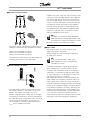
A high voltage test can be carried out by
short-circuiting terminals U, V, W, L1, L2 and L3
and energizing by max. 2.5 kV DC for one second
between this short-circuit and the chassis.
NB!:
The RFI switch must be closed (position
ON) when high voltage tests are carried out.
The mains and motor connection must be
interrupted in the case of high voltage tests of the total
installation if the leakage currents are too high.
Installation
■ Heat emission from VLT 6000 HVAC
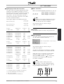
The tables in General technical data show the
power loss P (W) from VLT 6000 HVAC. The
maximum cooling air temperature tIN MAX, is 40°
at 100% load (of rated value).
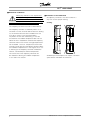
■ Ventilation of integrated VLT 6000 HVAC
The quantity of air required for cooling frequency
converters can be calculated as follows:
Add up the values of P for all the frequency
converters to be integrated in the same panel.
The highest cooling air temperature (t IN) present
must be lower than tIN, MAX (40°C). The day/night
average must be 5°C lower (VDE 160). The
outlet temperature of the cooling air must
not exceed: tOUT, MAX (45° C).
2. Calculate the permissible difference between
the temperature of the cooling air (tIN) and
its outlet temperature (tOUT ):
t = 45° C-tIN.
3. Calculate the required
m3/h
quantity of air =
t in Kelvin
insert
1.
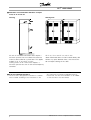
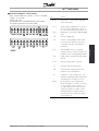
The outlet from the ventilation must be placed
above the highest-mounted frequency converter.
Allowance must be made for the pressure loss
across the filters and for the fact that the pressure
is going to drop as the filters are choked.
MG.60.C8.02 - VLT is a registered Danfoss trademark
11