1
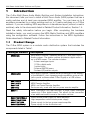
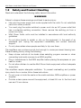
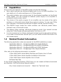
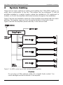
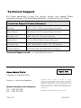
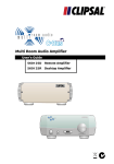
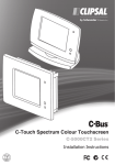
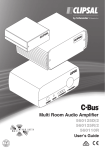
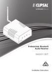
Multi Room Audio
Matrix Switcher and System
560884/2E
560884/2
Installation Instructions
Multi Room Audio Matrix Switcher and System
Installation Instructions
Contents
1
Introduction
1.1
1.2
1.3
1.4
2
Product Range
Safety and Product Handling
Capabilities
Related Product Information
System Cabling
2.1
2.2
2.3
2.4
2.5
2.6
2.7
3
AM/FM Antenna
Digital Audio
C-Bus Network
Speakers
Analogue Audio
Ethernet LAN
Infrared Control
Unit Connections
3.1
3.2
3.3
Matrix Switcher
Amplifiers
Distribution Unit
3
3
5
6
6
7
9
9
11
13
14
15
15
16
16
19
21
4
C-Bus Programming Requirements
22
5
Troubleshooting
24
6
Specifications
26
7
Standards Complied
28
8
Two-Year Warranty
29
The information in this manual is provided in good faith. Schneider Electric endeavours to
ensure the relevance and accuracy of the information. However, it assumes no responsibility
for any loss incurred as a result of its use. Schneider Electric does not warrant that the
information is fit for any particular purpose, nor does it endorse its use in applications that are
critical to the health or life of any human being. Schneider Electric reserves the right to
update the information at any time without notice.
January 2010
2
Multi Room Audio Matrix Switcher and System
1
Installation Instructions
Introduction
The C-Bus Multi Room Audio Matrix Switcher and System Installation Instructions,
this document, tells you how to install a Multi Room Audio (MRA) system that has a
matrix switcher and at least one connected MRA amplifier. You can have up to 8
amplifiers connected to a matrix switcher and up to 3 matrix switchers on a C-Bus
network. If you are installing MRA amplifiers in a standalone layout (without a matrix
switcher), refer to the documents listed in Related Product Information, Section 1.4.
Read the safety information before you begin. After completing the hardware
installation tasks, you must program the MRA Matrix Switcher and MRA amplifiers
using the configuration software. Follow the instructions in the MRA Application
Notes described in Related Product Information.
1.1
Product Range
The C-Bus MRA system is a modular audio distribution system that includes the
components listed in Table 1.
Catalogue Number
Description
560884/2
MRA Matrix Switcher, standard model for C-Bus Multi Room
Audio systems. The matrix switcher distributes digital audio to
up to 8 MRA zones. The switcher includes:
4 stereo analogue inputs
1 C-Bus digital audio
1 optical input
2 internal AM/FM tuners
2 infrared (IR) emitter outputs
560884/2E
MRA Matrix Switcher, deluxe model including all of the features
of the 560884/2, plus streaming audio capabilities using a LAN
(with special software called C-Bus Ripple) or a USB source.
560125D/2
560125R/2
560110R
560100E
MRA Desktop Amplifier
MRA Remote Amplifier
MRA Low Power Remote Amplifier
Enclosure only, used with the low power remote amplifier
560011
MRA Distribution Unit that encodes a single stereo analogue
source into C-Bus digital format. This allows for the connection
of an additional audio source to the matrix switcher.
5600P24/3750AU
Switch mode power supply for MRA amplifiers
5600P24H3750A
High temperature switch mode power supply
5600P24/1250
Power supply for the low power remote amplifier
5600P24/500AU
Power supply for the distribution unit
Table 1. Multi Room Audio product range
3
Multi Room Audio Matrix Switcher and System
Installation Instructions
Figure 1. Multi Room Audio system components
Figure 2. High temperature power supply and the power supply for the 560110R Low Power
Remote Amplifier
4
Multi Room Audio Matrix Switcher and System
1.2
Installation Instructions
Safety and Product Handling
Read and understand the following safety hazard information.
WARNINGS
Failure to observe these warnings could lead to serious injury:
•
Use only the power supply and cords supplied with the units. Do not substitute
parts from other products.
•
You must plug the matrix switcher's power cord into an AC power outlet that
has a protective earthing connection. Never remove the earthing pin from a
power cord plug.
•
Multi Room Audio units must be installed in accordance with local authority
guidelines.
•
Do not allow liquids to splash or drip on the equipment. In the event of an
accidental spill, unplug the equipment immediately and contact technical
support.
•
Do not place cables where people are likely to trip over them.
The amplifiers can produce sounds loud enough to cause permanent hearing loss.
Prevent hearing loss by doing the following:
•
Keep volume controls at low levels when selecting program sources or when
connecting local audio sources to an MRA amplifier.
•
Plug in headphones to the MRA amplifier before placing the earpieces on your
head or in ears.
•
Do not allow children to use the Multi Room Audio equipment without adequate
supervision.
The amplifiers require adequate ventilation. To prevent overheating and possible
injury due to fire or smoke, follow these instructions.
•
Do not cover or block the vents on the matrix switcher, MRA amplifiers or power
supplies.
•
Provide a clear space around the equipment, at least 50 mm to the front and
rear and 15 mm above.
5
Multi Room Audio Matrix Switcher and System
1.3
Installation Instructions
Capabilities
Some of the main features of the MRA system include the following:
• Each matrix switcher can distribute digital audio to up to 8 MRA amplifiers. You
can install up to 3 matrix switchers on a C-Bus network.
• The matrix switcher can provide power for the attached amplifiers via the Digital
Audio cables. You can connect an external power supply to an amplifier to
increase its audio power output.
•
The choice of the audio program for an amplifier can be made at the matrix
switcher or in the audio zone where the program is playing. You can use C-Bus
input devices to choose the source and to adjust volume, tone and muting.
•
The AM/FM tuners inside the matrix switcher can distribute preset station
choices to any of the audio zones.
•
The deluxe matrix switcher distributes streaming audio from several sources
using the C-Bus Ripple software application that runs on a PC.
•
You can connect up to 4 stereo analogue line-level inputs to the matrix switcher.
If you need to add another source input, you can install an MRA Distribution Unit
and power supply.
1.4
Related Product Information
The following application notes are required for the MRA installation process.
Application Note #1 – Configuring MRA with Toolkit Software
Application Note #2 – Configuring MRA with MARPA Software
Application Note #3 – Configuring MRA with PICED Software
Application Note #4 – Configuring C-Bus Ripple Software
Also, refer to the following documents, as needed.
C-Bus Multi Room Audio Matrix Switcher and System User's Guide
C-Bus Multi Room Audio Amplifier Installation Instructions
C-Bus Multi Room Audio Amplifier User's Guide
Software Help files
At the Clipsal Integrated Systems (CIS) Portal you can access software downloads
and literature. Visit the following Internet location:
http://www.clipsal.com/cis/portal
6
Select the 'Technical' area.
Multi Room Audio Matrix Switcher and System
2
Installation Instructions
System Cabling
There are two basic methods of cabling and installing the C-Bus MRA system; you
might use a combination of the two. The system can be configured (1) with all
amplifiers installed in a central location where the installation's A/V equipment is
located, or (2) with the amplifiers distributed remotely throughout the installation.
Figure 3 shows and installation where all of the amplifiers are located near the matrix
switcher. The speaker wires run from the central location to the audio zones.
Figure 4 shows the amplifiers placed remotely in the various zones.
Figure 3. An MRA system layout with centrally placed amplifiers
Caution
Do not plug a C-Bus network cable into a Digital Audio socket. You
could damage the matrix switcher or the amplifier.
7
Multi Room Audio Matrix Switcher and System
Installation Instructions
Figure 4. MRA amplifiers placed remotely in the various audio zones
Cabling is an important part of MRA system installation. Clipsal highly recommends
using network cables of different colours to prevent connection of digital, C-Bus and
LAN cables to the wrong connectors on the matrix switcher and amplifiers. Refer to
Table 2.
Application
Cable Type
C-Bus network
Digital audio
Ethernet LAN
AM/FM antenna
Speakers
Analogue audio
Infrared target
Cat.5e, 4 pair UTP
Cat.5e, 4 pair UTP
Cat.5e, 4 pair UTP
RG6 coaxial
2-core insulated
Shielded coaxial
3-core insulated
Recommended
Colour
pink
green
blue
black
any
any
any
Table 2. Recommended cable colours and types for MRA applications
8
Refer to
Section
2.3
2.2
2.6
2.1
2.4
2.5
2.7
Multi Room Audio Matrix Switcher and System
2.1
Installation Instructions
AM/FM Antenna
The RG6 coaxial antenna cable is terminated at the matrix switcher rear panel with a
Type-F connector. When using the cable for AM radio reception, you must break the
shield in the cable at some point away from the matrix switcher and associated
equipment.
Figure 5 shows the cable modification required for AM reception. It is not required if
you are using only FM reception.
Figure 5. Cable modification for AM reception
Refer to the Application Notes and the MARPA Help for more information about
selecting radio station presets.
2.2
Digital Audio
The matrix switcher sends the digital audio to each MRA amplifier. The Cat.5e Digital
Audio cables are terminated at the matrix switcher using an RJ45 plug. The cable
carries:
•
•
•
Digital audio signal
27 V d.c. to power the amplifier (see Note)
Signals for infrared (IR) reticulation
Note:
The matrix switcher can provide power for multiple MRA amplifiers using the Digital
Audio cable to distribute power. If you need more audio output power for an
amplifier, an external power supply can be installed.
Keep the following in mind when connecting the Digital Audio cables:
•
The Digital Audio outputs from the matrix switcher or distribution unit must only
be used with MRA amplifiers.
•
It is strongly suggested that a specific colour is used for Digital Audio cables,
with green being the suggested colour (see Table 2).
•
Do not exceed 45 metres maximum cable length for individual Digital Audio
cables.
9
Multi Room Audio Matrix Switcher and System
Installation Instructions
•
Avoid laying Digital Audio cables along side mains cabling, as electromagnetic
interference (EMI) can disrupt the audio signal.
•
You can terminate the Digital Audio cable at a wall plate and run the cables
inside the wall to the amplifier, or a wall plate near the amplifier. Then you can
use patch leads from the matrix switcher to the wall plate.
Note:
The MRA amplifiers can be configured using a loop in-loop out connection for
digital audio and IR, but not for power. Additional amplifiers will require a
separate power supply. Refer to the C-Bus Multi Room Audio Amplifier
Installation Instructions.
If loop-in, loop-out is required with the Low Power Remote amplifier, a
5600TEE will be needed.
Figure 6 shows the connections from the matrix switcher to the MRA amplifiers. In
the illustration, an optional MRA distribution unit provides an additional audio input
source.
Figure 6. Digital Audio cable connections
10
Multi Room Audio Matrix Switcher and System
2.3
Installation Instructions
C-Bus Network
The MRA system's matrix switcher and amplifiers must be on the same C-Bus
network. The matrix switcher and each amplifier has a C-Bus connection on the rear
panel.
The high power amplifiers and matrix switcher use C-Bus network cables that are
terminated with RJ45 plugs. The Low Power Remote Amplifier uses a removable
screw terminal connector. You may daisy chain C-Bus connections at the units. If
you use wall plates, they should be clearly marked as C-Bus connection points.
Table 3 and Figure 7 show the termination details for C-Bus network cables.
RJ45 pin
1
2
3
4
5
6
7
8
Signal Name
Remote ON
Remote ON
C-Bus negative (–)
C-Bus positive ( + )
C-Bus negative ( – )
C-Bus positive ( + )
Remote OFF
Remote OFF
Wire Colour
green & white
green
orange & white
blue
blue & white
orange
brown & white
brown
Table 3. C-Bus network cable data
Figure 7. C-Bus network cable termination
The catalogue numbers for the pink Cat.5e UTP cable are: 5005C305B (solid) and
5005C305BST (stranded).
11
Multi Room Audio Matrix Switcher and System
Installation Instructions
Figure 8 shows connection points for the C-Bus network cables on the matrix
switcher and the amplifiers.
Figure 8. C-Bus network connectors on the back panels
You can connect the matrix switcher and the MRA amplifiers to any convenient
connection point on the C-Bus network, as each unit has a unique network address.
Refer to the Application Notes for software configuration and programming
information.
C-Bus Power Requirements
The matrix switcher and each MRA amplifier draws 22 mA of power supply current
from the C-Bus network. The Network window of a C-Bus Toolkit project provides a
summary of a C-Bus network according to the units added to the database. This
can be helpful in determining the power supply requirements of a particular network.
Refer to Application Note #1 – Configuring MRA with Toolkit Software.
The C-Bus network is electrically isolated from building power. Do not tie the C-Bus
negative line to building earth or neutral.
The MRA Distribution Unit does not connect to C-Bus and therefore does not
impact on the power requirements of a C-Bus network.
C-Bus Indicators
The orange Unit indicator shows the status of the individual unit. When C-Bus is
connected, the indicator stays lit.
Indicator Mode
Off
On
Flashing
Table 4. Unit indicator meanings
12
Meaning
Not connected to C-Bus
C-Bus connected
Data is being exchanged
Multi Room Audio Matrix Switcher and System
Installation Instructions
The orange C-Bus indicator LED shows the status of the C-Bus network at the unit.
If sufficient network voltage (20 V d.c. to 36 V d.c.) and a valid network clock are
present, the indicator stays lit. If the network voltage is marginal, the indicator
flashes.
Indicator Mode
Off
On
Flashing at 4Hz rate
Meaning
No network clock is present and/or no
power is present.
Power is on and C-Bus network clock is
present.
The C-Bus network power is marginal
(15 V d.c. < voltage < 20 V d.c.)
Table 5. C-Bus indicator meanings
2.4
Speakers
Depending on the installation, speakers may be mounted on a wall using brackets,
flush mounted in a wall or concealed in a ceiling. When you mount speakers on
brackets, you should install a wall plate with RCA jacks near each speaker. Always
use stainless steel mounting hardware for outdoor speaker installations.
Use stranded, pure copper speaker cable. Quality speaker cable has low electrical
impedance. The impedance of the cable should not exceed 5% of the impedance of
the speaker.
Example:
If the cable and speaker have an impedance of 0.001Ω/m and 8Ω respectively,
(5% of 8 ) ÷ (0.001 x 2 conductors) = 200,
then the cable should not exceed 200 metres in length.
The high power MRA amplifiers use spring type connectors. The Low Power
Remote Amplifier uses screw type connectors.
Cautions
Avoid damage to the equipment by observing these cautions.
•
•
•
Do not allow the positive and negative speaker wires to short together.
Do not make any connection between speakers connected to different
amplifiers.
Do not connect any speaker wires to earth (ground).
Observe the positive (+) and negative (-) markings on the amplifier and make sure
that you consistently connect the cables to the speakers throughout the installation.
If speaker wire polarity is wrong, sound quality will be poor due to out-of-phase
sound from the various speakers.
13
Multi Room Audio Matrix Switcher and System
Installation Instructions
Figure 9. Amplifier loudspeaker terminals
2.5
Analogue Audio
The matrix switcher has 4 line-level local audio inputs labelled SOURCE INPUT. You
can use these stereo analogue inputs to play audio from locally connected
audio/video (A/V) equipment. Connect your A/V source using standard audio cables
with RCA connectors.
SOURCE INPUT 4 on the rear panel and the AUX input on the front panel of the
matrix switcher are electrically tied together. You cannot use these connections
simultaneously because poor audio quality will result.
The desktop amplifier and remote amplifier have a volume-controlled line-level input
labelled ZONE IN. Refer to Table 6 for connector types. The ZONE IN and ZONE
OUT connections can be used when amplifiers are configured in a standalone layout
without a matrix switcher or serve as a 'local input' for the zone. Refer to the C-Bus
Multi Room Audio Amplifier Installation Instructions and the Amplifier User's Guide.
Amplifier type
LOCAL IN
ZONE OUT
Headphones
Desktop
Remote
Low Power
Remote
2 – RCA jacks
2 – RCA jacks
3.5 mm stereo
2 – RCA jacks
2 – RCA jacks
N/A
3.5 mm stereo
N/A
N/A
Table 6. Connection types for the amplifier's local inputs and outputs
When installing audio cables:
• Avoid laying audio cable along side mains cable to minimise EMI pickup.
• Do not earth the audio negative ( – ) terminals.
• A separate ground wire from the A/V equipment to the matrix switcher is not
needed.
14
Multi Room Audio Matrix Switcher and System
2.6
Installation Instructions
Ethernet LAN
The deluxe matrix switcher model has streaming audio. Connect a Cat.5e cable with
an RJ45 connector to the LAN port on the matrix switcher's rear panel and connect
the other end of the cable to an Ethernet LAN switch or hub. Do not plug an
Ethernet LAN cable into the C-Bus or Digital Audio connectors on the matrix
switcher. When using the deluxe model matrix switcher, use a PC on the LAN to run
the C-Bus Ripple application. Refer to Application Note #4 – Configuring C-Bus
Ripple Software.
To change the configuration of the Networking capabilities, please consult
Application Note #2 – Configuring MRA with MARPA Software, that includes details
for this process.
2.7
Infrared Control
An optional IR target device can be connected to the IR TARGET socket on the rear
panel of an amplifier. This connection allows an IR remote control (for example a
universal learning-type remote control) to operate audio source equipment that is
fitted with IR emitters connected to the matrix switcher as shown in Figure 10.
Note:
IR signals received by external IR targets cannot directly control MRA amplifiers.
Such control is accomplished using the IR receiver built into the front panel of the
MRA Desktop Amplifier and the amplifier's remote control.
Figure 10. IR control signal path for the MRA system
As shown in Figure 10, a Clipsal 8055TT Tube IR Target or an 8050ST Shelf Top
Target is wired to the amplifier. Extend the cable, if necessary, and use a 3.5 mm
stereo socket on a wall plate adjacent to the amplifier.
Figure 11. IR target cable termination
15
Multi Room Audio Matrix Switcher and System
3
Installation Instructions
Unit Connections
This section contains diagrams and descriptions of the connection points, indicators
and controls on the various Multi Room Audio components.
3.1
Matrix Switcher
Be sure to power off the equipment when connecting or disconnecting digital
cables. The digital audio cables also distribute power between certain components
and must not be disturbed when power is on.
Figure 12. Matrix switcher rear panel connections and indicators
Connection
/Indicator
Description or Function
Power switch
Switches the unit on and off.
Power cord
connector
Connect the power cord here to power the matrix switcher. The
matrix switcher also provides power for connected amplifiers
that do not have an external power supply.
IR OUT
2 – 3.5 mm
These 3.5 mm sockets connect to IR Emitter leads. IR Emitters
are then coupled to IR receivers on A/V equipment to provide
remote control from any zone.
BROADCAST inputs
2 – RCA
Line level mono audio that is connected here is broadcast to all
zones that have an analogue input source or radio station
selected. The mono inputs have different priorities.
Audio connected to the LO input is sent by amplifiers at their
current level to the RIGHT hand speakers.
Audio connected to the HI input is sent at a preset level to the
LEFT and RIGHT hand speakers.
16
Multi Room Audio Matrix Switcher and System
Installation Instructions
HI/LO adjustment
2 – trimpots
These adjust the level of the audio source connected to the
mono broadcast inputs. Use a small Phillips screwdriver to
rotate the control if the audio source is too quiet or loud.
USB
1– Type B
This connection is used for programming the matrix switcher
during commissioning by the installer using a PC running
MARPA configuration software.
LAN
1 – RJ45
This RJ45 socket enables connection to a local (computer)
network for the streaming functionality on the deluxe matrix
switcher.
OPTICAL
IN/OUT
Used to connect a digital optical audio source for distribution to
any of the eight zones. The digital audio format must be 44.1 or
48 kHz stereo. Some digital audio formats (such as surround
sound) are not compatible with the Matrix Switcher. The optional
output is provided so that the input can be sent on to another
piece of A/V equipment. You cannot use the optical input and
the DIGITAL AUDIO IN at the same time.
DIGITAL AUDIO
OUT
8 – RJ45
Each zone output is used to connect the matrix switcher to one
amplifier in each audio zone. Additional amplifiers can be added
to a zone by connecting their DIGITAL AUDIO IN socket to the
DIGITAL AUDIO OUT of a Desktop or Remote Amplifier. The
Low Power Amplifier requires a 5600TEE, as it has only a
DIGITAL AUDIO IN connection.
DIGITAL AUDIO
IN
1 – RJ45
Use this connection when using an optional MRA Distribution
Unit to provide an additional stereo audio input.
SOURCE INPUT
4 – RCA pairs
Most A/V devices connect to the matrix switcher through the
four standard stereo analogue inputs. These are line-level RCA
sockets numbered 1 through 4. Input 4 is electrically tied to the
front panel AUX connector. This input should be used as either a
line level input (rear panel) or a headphone-level input (AUX
input), not both; Note that the Input 4/AUX inputs have different
gain levels than the other 3 analogue inputs.
AM/FM antenna
1 – Type-F coaxial
One antenna connection serves both internal AM/FM tuners.
C-Bus
2 – RJ45
There are two connections for the C-Bus network to allow for
looping through to additional pieces of equipment.
Unit indicator and
C-Bus indicator
Unit and C-Bus indicators show network status and activity.
Refer to Section 2.3 for indicator functions.
Table 7. Matrix Switcher rear panel connections and indicators
17
Multi Room Audio Matrix Switcher and System
Installation Instructions
Figure 13. Matrix switcher front panel connections and indicators
Connection
/Indicator
Description or Function
LCD screen
The screen shows the program selection choices. Pressing a
Zone selection button displays the name and input source of the
zone. If one or more internal tuners are configured, the active
radio station(s) along with the approximate signal strength will be
displayed on this screen.
Zone selection
pushbuttons
The eight pushbuttons allow you to select the audio program for
each connected audio zone. Pressing the button again within 8
seconds selects the next input source and routes it to the zone.
USB socket
1 – Type A
The front USB socket allows for the insertion of a USB drive with
music loaded to be played using the streaming audio feature on
a deluxe matrix switcher. This USB socket operates
independently from the USB programming socket located on
the rear panel.
AUX
1 – 3.5 mm stereo
This connector lets you connect an audio source, such as a
portable audio player. The AUX socket is internally wired to
Source Input 4 at the back of the unit. If you are using the front
panel AUX connection, do not attach cables to Source Input 4 at
the rear panel.
Table 8. Matrix Switcher front panel switches and indicators
18
Multi Room Audio Matrix Switcher and System
3.2
Installation Instructions
Amplifiers
Be sure to remove power from the amplifier before connecting or disconnecting
cables. The amplifier is powered by an external power supply or by the matrix
switcher through the digital audio cable.
Not all cable connection points are used in every installation. Figure 14 shows the
connection points and indicators on the rear panel of the amplifiers.
Figure 14. MRA Amplifiers rear panel connections and indicators
19
Multi Room Audio Matrix Switcher and System
Installation Instructions
Connection
/Indicator
Description
Speaker outputs
The Desktop and Remote Amplifiers use spring-type connectors.
The Low Power Amplifier uses screw-terminal connections.
Headphones
1 – 3.5 mm
stereo
This connector is usually wired to a wall plate. The headphones
operate independently from the speakers. Use the mute button to
turn the speakers on and off.
External power
input
This connects power to the amplifier. An external power supply is
connected when a matrix switcher is not used, or to increase the
high power amplifiers' audio output capacity to 25 W RMS into
4-ohm speakers.
DIGITAL AUDIO
IN
1 – RJ45
The zone output of the Matrix Switcher is connected to this input.
Alternatively, a Distribution Unit can be connected to this input,
providing one stereo audio input. MRA amplifiers can select
between digital audio input and local input.
DIGITAL AUDIO
OUT
1 – RJ45
This is used to connect an additional amplifier for use in the same
audio zone. Both Amplifiers will use the same audio source). A
Cat.5e cable is used to connect to the digital audio input of the
second amplifier using a 5600TEE adapter.
LOCAL IN
1 – RCA pair, or
3.5 mm stereo
Use this to connect a local analogue audio source that is available
to this amplifier only.
ZONE OUT
1 – RCA pair
These are line level outputs of the selected audio source as
received by the amplifier. The volume, bass and treble settings of
the amplifier affect the outputs.
Digital optical
input
Use this to connect a digital optical audio source to the amplifier.
Either a digital audio (zone) or digital optical audio source may
be connected to the Amplifier, but not both simultaneously.
The digital audio format must be 44.1 or 48 kHz stereo. Some
digital audio formats (such as surround sound) are not compatible
with the Amplifier.
IR TARGET
This socket connects to an IR Target, allowing an infrared remote
to control equipment located near the matrix switcher (through
emitters connected to the matrix switcher).
C-Bus
2 – RJ45, or
screw terminal
Connects to the C-Bus network. The Low Power Remote Amplifier
uses a screw terminal connector.
Unit and C-Bus
indicators
Refer to Section 2.3.
Table 9. Amplifier connectors and indicators
20
Multi Room Audio Matrix Switcher and System
3.3
Installation Instructions
Distribution Unit
Figure 15. Distribution Unit connections and indicators
Connection /
Indicator
Description
Audio input
2 – RCA
The line-level stereo analogue audio connection.
IR emitter output
1 – 3.5 mm
This socket connects to an IR Emitter lead. IR Emitters can be
coupled to IR receivers on equipment, providing remote control
from any zone through the Multi Room Audio system.
Power Supply input
The 24 V d.c. Distribution Unit Power Supply is used when
connecting the Distribution Unit to a matrix switcher. The power
supply is not required when the digital audio output is connected
to the digital audio input of an amplifier.
Power indicator
Indicates that power is connected to the unit.
Digital Audio Output
1 – RJ45
This RJ45 connection outputs the digital audio that has been
converted from the analogue input. This connects to a digital
input on the matrix switcher or amplifier.
Table 10. Distribution Unit connectors and indicators
21
Multi Room Audio Matrix Switcher and System
4
Installation Instructions
C-Bus Programming Requirements
After an MRA system has been installed, it must be configured using C-Bus Toolkit
software and the Multi Room Audio Rapid Programming Application (MARPA).
Toolkit software lets you do the following:
•
Create a C-Bus project with a Group Address structure that is used by MRA
amplifiers and the MARPA software.
•
Enable a C-Bus system clock and burden in the matrix switcher (if required).
•
Configure each MRA amplifier so one or more C-Bus wall switches can control
it.
Please download Application Note #1 – Configuring MRA with Toolkit Software for
further information.
MARPA software lets you do the following:
•
Assign an ID to the matrix switcher (in case multiple matrix switchers are used
on the same network of a C-Bus installation).
•
Configure parameters for each audio source, for example:
o Define the label (description) displayed when the source is selected.
o Configure optional audio annunciation when the source is selected.
o Set the gain/attenuation for each source.
o Configure sources and radio station presets.
o Determine which C-Bus commands are triggered by the Dynamic
controls.
•
Configure parameters for each zone, including,
o whether labels are sent to C-Bus DLT switches.
o whether the local input source is available.
o IR maps for dynamic control (if used).
MARPA also includes a bundled version of the C-Bus IP Utility for configuring the
network streaming feature in the deluxe matrix switcher.
Please download Application Note #2 – Configuring MRA with MARPA Software for
further information.
If your installation includes one or more touchscreens, you will require PICED
programming software (version 4.8 or higher) for configuration.
Please download Application Note #3 – Configuring MRA with PICED Software for
further information.
22
Multi Room Audio Matrix Switcher and System
Installation Instructions
If your matrix switcher has streaming audio capabilities, you will also use the C-Bus
Ripple server software application.
Please download Application Note #4 – Configuring C-Bus Ripple Software for
further information.
Using software not provided or approved by Clipsal could void the hardware
warranty.
The latest version of Toolkit, MARPA and C-Bus Ripple software can be
downloaded free of charge at the following location.
http://www.clipsal.com/cis/portal, select Technical and then select Downloads
C-Bus System Clock and Burden
The MRA matrix switcher and amplifiers incorporate a software selectable C-Bus
system clock. The system clock is used to synchronise data communication over a
C-Bus network. At least one active C-Bus system clock is required on each C-Bus
network for successful communication. No more than three units on a C-Bus
network should have their clock enabled, so this option is normally disabled using
Toolkit. The MRA matrix switcher and amplifiers incorporate a software selectable
network burden. The network burden can be enabled when editing the unit in C-Bus
Toolkit software, but only if the C-Bus system clock is also enabled.
23
Multi Room Audio Matrix Switcher and System
5
Installation Instructions
Troubleshooting
Symptom
Possible Explanation
There is no sound after switching
the amplifier on (sound worked
previously).
The volume may have been set to minimum,
or the amplifier may have been muted (on a
desktop amplifier) before the amplifier was
switched off.
The default volume, bass or treble
settings have changed (when
switching the amplifier on).
If a power failure occurs when the amplifier is
on, the volume, bass and treble settings are
saved and become the new defaults.
Unexpected behaviour occurs
after the digital zone connections
are changed.
The Amplifier’s zone settings are not reset
until all power is removed from the amplifier.
Alternatively use the Reset Amplifier function
on the unit’s C-Bus Status tab in Toolkit.
The wrong amplifier is responding
to source changes.
The “Use Matrix Switcher auto assigned
zone” option may not be enabled. This
option is in the amplifier’s Zoning tab in
Toolkit. After changing the status of this
option (on a live network), use the Reset
Amplifier function on the C-Bus Status tab.
The matrix switcher no longer
responds to button presses.
Turn the matrix switcher off for several
seconds, then on. Use the power switch on
the rear of the matrix switcher, next to the
power cord socket.
The matrix switcher does not
power up.
The fuse may need replacing. Remove the
power cord from the power outlet before
replacing the fuse.
A mains circuit breaker trips when
amplifiers are powered up.
This may occur if more than five amplifier
power supplies are connected to the same
circuit, due to a high inrush current.
24
Multi Room Audio Matrix Switcher and System
Installation Instructions
Symptom
Possible Explanation
Dynamic labels don’t work on a
C-Bus DLT wall switch.
There are several options that need to be
selected for labels to function. These options
are located:
on the More panel accessed by clicking the
“More....” button on the amplifier’s C-Bus
Control tab in Toolkit.
on the DLT wall switch’s Global tab in
Toolkit.
on the Zones branch of the Project tree in
MARPA.
An
amplifier
switches
off,
particularly when the volume is
loud.
If insufficient current is available for the
Amplifier, it will switch itself off. This may
occur if the amplifier receives its power from
a matrix switcher. The amplifier may need its
own external power supply unit.
An Amplifier emits a high-pitched
screeching
sound
when
a
particular source is selected.
This may occur if an output of an amplifier is
connected to the input of the matrix
switcher. Such a connection should be
avoided as it can cause a feedback loop.
Audio is not broadcast via the
matrix switcher’s high priority (HI)
broadcast input.
The level of the audio connected to the
broadcast input may not be sufficient to
trigger the broadcast.
Cannot hear any sound when
using the optical input
The digital audio source may be connected
to the optical output instead of the input (on
a matrix switcher). Some digital audio
formats (such as surround sound) are
incompatible with the MRA system.
Table 11. Troubleshooting symptoms and possible causes
25
Multi Room Audio Matrix Switcher and System
6
Installation Instructions
Specifications
Matrix Switcher
Parameter
Description
Supply Voltage
220 – 240 V a.c.
Mains frequency range
47 to 53 Hz and 57 to 63 Hz
Power consumption
220 VA maximum
C-Bus network voltage
15 to 36 V d.c.
C-Bus sink current
22 mA; the matrix switcher does not supply
current to the network
C-Bus AC input impedance
80 kΩ at 1KHz
Network clock and burden
Software selectable
Source input signal level
2.8 V p-p maximum (47 k Ω)
A/D conversion
16 bit PCM
Operating temperature
10 to 40 °C (50 to 104 °F)
Operating humidity
10 to 90% RH (non-condensing)
Figure 16. Matrix Switcher dimensions
26
Multi Room Audio Matrix Switcher and System
Installation Instructions
Distribution Unit
Parameter
Description
Supply Voltage
27 V d.c. when powered by amplifier via digital audio
connection, or
24 V DC @ 500 mA when using an external power
pack
Analogue input signal level
2.8 V p-p maximum (31 k Ω)
A/D conversion
16 bit PCM
Operating temperature
10 to 40° C (50 to 104° F)
Operating humidity
10 to 90% RH (non-condensing)
Figure 17. Distribution Unit dimensions
System Audio Output Specifications
Parameter
Description
Frequency response
40 Hz to 20 kHz (+2.4 dB / -0.75 dB)
Total harmonic distortion
(1 kHz, 20 W RMS into 4 Ω)
0.16% at 1 kHz, 20 W RMS into 4 ohms
Signal to noise ratio
> 63 db (peak, unweighted)
27
Multi Room Audio Matrix Switcher and System
7
Installation Instructions
Standards Complied
DECLARATIONS OF CONFORMITY
The matrix switcher complies with the following:
Australian/New Zealand EMC & Electrical Safety Frameworks and Standards
Regulation
Standard
Title
Electrical Safety *
AS/NZS 60065
Audio, video and similar electronic
apparatus - Safety requirements
EMC
AS/NZS CISPR 22
Information technology equipment Radio disturbance characteristics
(emissions)
European Directives and Standards
European Council
Directive
Standard
Title
2006/95/EC LVD
EN 60065
Audio, video and similar electronic
apparatus – Safety requirements
2004/108/EC
EN 55022
Information technology equipment –
Radio Disturbance Characteristics –
Limits and Methods of Measurement
EN 55024
Information technology equipment –
Immunity Characteristics – Limits &
Methods of Measurement
2002/95/EC RoHS
Reduction of hazardous substances
Other International Directives and Standards
28
Directive
Standard
Title
2004/108/EC
CISPR 22
Information technology equipment –
Radio Disturbance Characteristics
(emissions)
CISPR 24
Information technology equipment –
Immunity Characteristics
IEC 60065
Audio, video and similar electronic
apparatus – Safety requirements
Multi Room Audio Matrix Switcher and System
8
Installation Instructions
Two-Year Warranty
The C-Bus Multi Room Audio System Products carry a two-year warranty against
manufacturing defects.
Warranty Statement
The benefits conferred herein are in addition to, and in no way shall be deemed to derogate;
either expressly or by implication, any or all other rights and remedies in respect to the
Schneider Electric product, which the consumer has in the location where the product is sold.
The warrantor is Schneider Electric with offices worldwide.
This Schneider Electric product is guaranteed against faulty workmanship and materials for a
period of two (2) years from the date of installation.
Schneider Electric reserves the right, at its discretion, to either repair free of parts and labour
charges, replace or offer refund in respect to any article found to be faulty due to materials,
parts or workmanship.
This warranty is expressly subject to the Schneider Electric product being installed, wired,
tested, operated and used in accordance with the manufacturer's instructions. Any alterations
or modifications made to the product without permission of Schneider Electric might void the
warranty.
Schneider Electric shall meet all costs of a claim. However, should the product that is the
subject of the claim be found to be in good working order, all such costs shall be met by the
claimant.
When making a claim, the consumer shall forward the Schneider Electric product to the
nearest Schneider Electric office. Provide adequate particulars of the defect within 28 days of
the fault occurring. The product should be returned securely packed, complete with details of
the date and place of purchase, description of load, and circumstances of malfunction.
For all warranty enquiries, contact your local Clipsal sales representative. The
address and contact number of your nearest sales office can be found at
http://www.clipsal.com/locations or by telephoning Clipsal CIS Technical Support
1300 722 247 (CIS Technical Support Hotline).
29
Multi Room Audio Matrix Switcher and System
This page is left blank for formatting purposes.
30
Installation Instructions
Multi Room Audio Matrix Switcher and System
Installation Instructions
This page is left blank for formatting purposes.
31
Technical Support
For further assistance in using this product, consult your nearest Clipsal
Integrated Systems (CIS) Sales Representative or Technical Support Officer.
Technical Support Contact Numbers
Australia
1300 722 247 (CIS Technical Support Hotline)
New Zealand
0800 888 219 (CIS Technical Support Hotline)
Northern Asia
+852 2484 4157 (Clipsal Hong Kong)
South Africa
011 314 5200 (C-Bus Technical Support)
Southern Asia
+603 7665 3555 Ext. 236 or 242 (CIS Malaysia)
United Kingdom
0870 608 8 608 (Schneider Electric Support)
Technical Support email:
[email protected]
Clipsal Australia Pty Ltd
clipsal.com
A member of Schneider Electric
Contact us clipsal.com/feedback
National Customer Care Enquiries:
Tel 1 300 202 525
Fax 1 300 202 556
F1911/03
Schneider Electric reserves the right to change
specifications, modify designs and discontinue items without
incurring obligation. Every effort is made to ensure that
descriptions, specifications and other information in this
instruction booklet are correct. No warranty is given in
respect thereof and the company shall not be liable for any
error therein.
Copyright by Schneider Electric. All rights reserved.
10319732