1
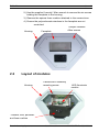
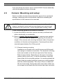
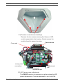
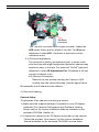
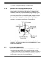
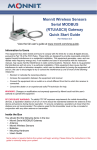
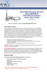
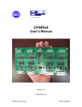
EX36‑IP No-Grip Corner
Mount Camera
EX36-IP
en
Installation Manual
EX36-IP
| en
1
Important safety instructions
Type numbers: NEC-360F02-11 |NEC-360F02-21 |NEC-360F04-11
NEC-360F04-21 INEI-368F04-11 |NEI-368F04-21 |NEI-368F04-11
NEI-368F04-21 INEI-369F02-11 |NEI-369F02-21 |NEI-369F04-11
NEI-369F04-21
Read, follow, and retain all of the following safety instructions. Heed all warnings on
the unit and in the operating instructions.
1.
Cleaning - Unpower the unit before cleaning. Follow any instructions provided
with the unit. Generally, using a dry cloth for cleaning is sufficient, but a moist
fluff-free cloth or leather shammy may also be used. Do not use liquid
cleaners or aerosol cleaners.
2.
Heat Sources - Do not install the unit near any heat sources such as radiators,
heaters, stoves, or other equipment (including amplifiers) that produce heat.
3.
Object and liquid entry - Never push objects of any kind into this unit through
openings as they may touch dangerous voltage points or short-out parts that
could result in a fire or electrical shock. Never spill liquid of any kind on the
unit. Do not place objects filled with liquids, such as vases or cups, on the unit.
4.
Controls adjustment - Adjust only those controls specified in the operating
instructions. Improper adjustment of other controls may cause damage to the
unit. Use of controls or adjustments, or performance of procedures other than
those specified, may result in hazardous radiation exposure.
5.
Overloading - Do not overload outlets and extension cords. This can cause
fire or electrical shock.
6.
Power sources - Operate the unit only from the type of power source indicated
on the label. Before proceeding, be sure to disconnect the power from the
cable to be installed into the unit.
- For external power supplied units, use only the recommended or approved
power supplies.
- For limited power source units, this power source must comply with
EN60950. Substitutions may damage the unit or cause fire or shock.
- For 24 VAC units, voltage applied to the unit's power input should not
exceed 24 VAC. User-supplied wiring must comply with local electrical
codes (Class 2 power levels). Do not ground the supply at the terminals or
at the unit's power supply terminals.
- If unsure of the type of power supply to use, contact your dealer or local
power company.
7.
Damage requiring service - Unplug the unit from the main AC power source
and refer servicing to qualified service personnel when any damage to the
equipment has occurred, such as:
- the power supply cord or plug is damaged;
Bosch Security Systems
Quick Install
MAN36IPB Rev.0 | 2008.10
2
en |
8.
9.
10.
EX36-IP
- liquid has been spilled in or on the equipment;
- an object has fallen into the unit;
- unit has been dropped or the unit cabinet is damaged;
- unit exhibits a distinct change in performance;
- unit does not operate normally when the user correctly follows the
operating instructions.
Safety check - Safety checks should be performed upon completion of service
or repairs to the unit to ensure proper operating condition.
Installation - Install in accordance with the manufacturer's instructions and in
accordance with applicable local codes.
Attachments, changes, or modifications - Only use attachments/accessories
specified by the manufacturer. Any change or modification of the equipment,
not expressly approved by Bosch, could void the warranty or, in the case of
an authorization agreement, authority to operate the equipment.
i
o
!
!
i
DANGER! High risk: This symbol indicates an imminently hazardous
situation such as " Dangerous Voltage " inside the product. If not
avoided, this will result in an electrical shock, serious bodily injury, or
death.
CAUTION! Alerts the user to the risk of damage to the unit
WARNING! Medium risk: Indicates a potentially hazardous situation.
If not avoided, this may result in minor or moderate injury. Alerts the
user to important instructions accompanying the unit.
NOTE! This symbol indicates information or a company policy that
relates directly or indirectly to the safety of personnel or protection of
property.
o
MAN36IPB Rev.0 | 2008.10
Quick Install
Bosch Security Systems
EX36-IP
| en
3
The full version Installation Manual is available on the enclosed CD-ROM and can
be viewed and printed out with Acrobat Reader, which is also on the enclosed
CD-ROM. This user guide is the intellectual property of BOSCH Security Systems
and is protected by copyright
CAUTION!
–
Camera Grounding - For mounting the camera in potentially
damp environments, ensure to ground the system using the
ground connection of the power supply connector (see section:
Connecting external power supply).
–
U.S.A. models only - Section 810 of the National Electrical
Code, ANSI/NFPA No.70, provides information regarding proper
!
grounding of the mount and supporting structure, grounding of
the coax to a discharge unit, size of grounding conductors, location of discharge unit, connection to grounding electrodes, and
requirements for the grounding electrode.
–
Permanently connected equipment - Incorporate a readily
accessible disconnect device in the building installation wiring.
–
Power lines - Do not locate the camera near overhead power
lines, power circuits, or electrical lights, nor where it may contact
such power lines, circuits, or lights.
Bosch Security Systems
Quick Install
MAN36IPB Rev.0 | 2008.10
4
en |
1.1
EX36-IP
Unpacking
Parts list (items supplied with unit)
- EX36IP Infrared Imager™ Assembly
- Installation Instructions booklet
- Allen Key
- Software CD
Items required for installation
(not supplied with units)
- Mounting hardware
- Mounting tools
- PC/Laptop with RJ45 Ethernet port
- Power supply
1.2
Initial Preparations
1.) Determine the operating voltage at the installation site. The
camera‘s Voltage Regulator Board accepts 12-24VAC / VDC input
without change to internal connections.
2.) Determine the optimum mounting location for the camera. See
Section 2, Mounting the unit.
3.) All cameras have been tested and pre-focused with telephoto
setting as factory default prior to shipment. If any adjustment
needed, it is advisable to check the camera’s operation before
installation
4.) Install IP Camera Software on PC.
2.
Mounting the unit
2.1
Faceplate removal
The faceplate must be removed prior to the installation process.
This is necessary because the mounting holes need to be accessed.
The lens may need to have its directional angle changed.
1.) Place the camera housing on a flat surface.
MAN36IPB Rev.0 | 2008.10
Quick Install
Bosch Security Systems
EX36-IP
| en
5
2.) Use the supplied “security” Allen wrench to remove the six screws
holding the faceplate to the housing.
3.) Remove the square foam cushion attached to the camera lens.
4.) Ensure the polycarbonate windows in the faceplate are not
scratched.
Housing
Faceplate
Tamper resistant
Allen screws
Tamper resistant
Allen screws
2.2
Layout of modules
Housing
Camera/LED assembly
mounting screw
LED illuminator
module
Camera, lens, photocell
and foam cushion
Bosch Security Systems
Quick Install
MAN36IPB Rev.0 | 2008.10
6
en |
EX36-IP
This view shows the interior layout of the EX36IP Camera assembly
after the faceplate has been removed.
2.3
Camera: Mounting and setup:
Select a suitable location that protects the camera from accidental
damage, tampering and environmental conditions exceeding the
specifications of the camera to be mounted.
!
CAUTION! Ensure the selected location is protected from falling
objects, accidental contact with moving objects and unintentional
interference from personnel. Follow all applicable building codes.
These mounting guidelines should be followed:
1.) Locate the bracket such that it cannot be easily interfered with,
either intentionally or accidentally.
2.) Select a smooth, flat mounting surface to ensure proper sealing.
The surface must also be capable of supporting the combined
weight of the camera and mounting hardware under all expected
conditions of vibration and temperature. Camera performs best
mounted approximately 3m off the ground.
2.1) Camera housing mounting
Installations on drywall must use #8 screws and #8 drywall
nylon plugs or a superior connection. The camera’s mounting
holes are located on the left and right side of the housing.
Refer to figure below. Depending on the type of mounting
surface (brick, wood, etc.), it may be necessary to pre-drill
these holes for the mounting screws. It is recommended that
these holes be marked using the housing as a drill template
and then drilled separately. This way no burrs or debris will
fall into the housing. Ensure the power and video cables are
not crimped or stressed after the camera has been mounted.
MAN36IPB Rev.0 | 2008.10
Quick Install
Bosch Security Systems
EX36-IP
| en
7
Mounting holes
2.2) Camera connections and settings
Remove the two screws securing the Camera / LED
module assembly to the housing. Gently remove the
module from the camera housing.
Camera board
Foam pad
Analog video
connection
Photocell
adjustment pot
IR adjustment
pot
2.3) LED array-power adjustments
The EX36IP needs to be powered-up while making the LED
power adjustments. Cover the photocell to turn the LEDs
Bosch Security Systems
Quick Install
MAN36IPB Rev.0 | 2008.10
8
en |
EX36-IP
Ethernet
connector
“ON” (850nm LEDs will have a slight red glow). Adjust the
LED power if they are too bright or too dim. For IR power
adjustment, rotate VR1. Clockwise is high and counterclockwise is low.
2.4) Photocell adjustment
The photocell is factory set optimum level. In some conditions such as with bright foreground objects the camera may
switch too early or too late. For photocell “On/Off” light-level
adjustment, rotate IR Adjustment Pot. Clockwise is off and
counter-clockwise is on.
2.5) Ethernet Connection.
Remove the two screws securing the Camera / LED
module from the camera housing. See the figure below.
Re-assemble the IP board into the chassis.
3.) Secure all cabling.
Camera Setup:
To determine if the camera is receiving a picture:
1.) Make sure the supplied software is installed in your PC/laptop
computer (For Camera Configuration and Software Viewing
Setup, refer to full version Installation Manual available on the
enclosed CD-ROM -Section 4).
2.) Connect the camera to the PC/laptop and power up the camera.
Follow the prompts. See section 2 of full version Installation
Manual available on the enclosed CD-ROM for more detail.
MAN36IPB Rev.0 | 2008.10
Quick Install
Bosch Security Systems
EX36-IP
| en
9
3.) Launch Configuration Manager or web-browser.
2. 4
Camera-directional adjustments
Both the camera and the LED array can be adjusted for optimum
picture quality. The camera lens can be tilted on its axis via two
adjustment screws on the mounting bracket. It can also be moved
closer or farther away from the viewing window. Connect the Ethernet
and power wires. Mount the Camera/LED Array Assembly into the
housing. Check the picture for quality and directional alignment.
Remove the Camera/LED Array Assembly if an adjustment is
required to the camera’s viewing angle or picture quality.
Loosen both adjustment screws for tilt or horizontal directional
alignment. This action may require trial-and-error attempts to obtain
perfect picture alignment.
2.5
Camera re-assembly
Make sure all wires are properly connected, all holes are sealed
against moisture penetration, and all mounting screws are tight.
1.) Slide the lens foam over the camera lens. Make sure the foam is
snug and as close to the faceplate viewing window as possible and
the photocell is secure with an unobstructed view.
Bosch Security Systems
Quick Install
MAN36IPB Rev.0 | 2008.10
10 en |
i
Note: Use Infra-Red Pass filter to cover the lens during focusing to
EX36-IP
simulate low light conditions on scene for correct 24-hour focusing.
For camera with manual iris lens, the camera should be focused with
2.) Attach the faceplate to the camera housing. Insert and tighten the
the lens iris fully opened to simulate the worst possible depth of field.
6 bolts.
Using a Infra-Red Pass filter will ensure the iris is fully open for
3.) Power-up the camera and check its operation.
correct setup and adjustment.
Note that statement above is applicable only for Day/Night or IR
version cameras.
2.6
Camera re-assembly
Make sure all wires are properly connected, all holes are sealed
against moisture penetration, and all mounting screws are tight.
1.) Slide the lens foam over the camera lens. Make sure the foam is
snug and as close to the faceplate viewing window as possible
and the photocell is secure with an unobstructed view.
2.) Attach the faceplate to the camera housing. Insert and tighten the
6 bolts.
3.) Power-up the camera and check its operation.
MAN36IPB Rev.0 | 2008.10
Quick Install
Bosch Security Systems
Americas
Bosch Security Systems, Inc.
850 Greenfield Road
Lancaster, Pennsylvania 17601
USA
Telephone +1 888-289-0096
Fax
+1 585-223-9180
Email: [email protected]
www.boschsecurity.us
Europe, Middle East, Africa:
Bosch Security Systems B.V.
P.O. Box 80002
5600 JB Eindhoven, The
Netherlands
Phone: + 31 40 2577 284
Fax: +31 40 2577 330
[email protected]
www.boschsecurity.com
Asia-Pacific:
Bosch Security Systems Pte Ltd
38C Jalan Pemimpin
Singapore 577180
Phone: +65 6319 3450
Fax: +65 6319 3499
[email protected]
www.boschsecurity.com
© Bosch Security Systems, Inc. 2009; Data subject to change without notice.